US5534133A - Continuous method for increasing the Q. I. concentration of liquid tar while concurrently producing a Q. I. free tar - Google Patents
Continuous method for increasing the Q. I. concentration of liquid tar while concurrently producing a Q. I. free tarDownload PDFInfo
- Publication number
- US5534133A US5534133AUS08/341,395US34139594AUS5534133AUS 5534133 AUS5534133 AUS 5534133AUS 34139594 AUS34139594 AUS 34139594AUS 5534133 AUS5534133 AUS 5534133A
- Authority
- US
- United States
- Prior art keywords
- tar
- feed
- circulation loop
- permeate
- flow
- Prior art date
- Legal status (The legal status is an assumption and is not a legal conclusion. Google has not performed a legal analysis and makes no representation as to the accuracy of the status listed.)
- Expired - Fee Related
Links
Images


Classifications
- B—PERFORMING OPERATIONS; TRANSPORTING
- B01—PHYSICAL OR CHEMICAL PROCESSES OR APPARATUS IN GENERAL
- B01D—SEPARATION
- B01D61/00—Processes of separation using semi-permeable membranes, e.g. dialysis, osmosis or ultrafiltration; Apparatus, accessories or auxiliary operations specially adapted therefor
- B01D61/14—Ultrafiltration; Microfiltration
- B01D61/147—Microfiltration
- B—PERFORMING OPERATIONS; TRANSPORTING
- B01—PHYSICAL OR CHEMICAL PROCESSES OR APPARATUS IN GENERAL
- B01D—SEPARATION
- B01D61/00—Processes of separation using semi-permeable membranes, e.g. dialysis, osmosis or ultrafiltration; Apparatus, accessories or auxiliary operations specially adapted therefor
- B01D61/14—Ultrafiltration; Microfiltration
- B01D61/145—Ultrafiltration
- B—PERFORMING OPERATIONS; TRANSPORTING
- B01—PHYSICAL OR CHEMICAL PROCESSES OR APPARATUS IN GENERAL
- B01D—SEPARATION
- B01D61/00—Processes of separation using semi-permeable membranes, e.g. dialysis, osmosis or ultrafiltration; Apparatus, accessories or auxiliary operations specially adapted therefor
- B01D61/14—Ultrafiltration; Microfiltration
- B01D61/22—Controlling or regulating
- C—CHEMISTRY; METALLURGY
- C10—PETROLEUM, GAS OR COKE INDUSTRIES; TECHNICAL GASES CONTAINING CARBON MONOXIDE; FUELS; LUBRICANTS; PEAT
- C10C—WORKING-UP PITCH, ASPHALT, BITUMEN, TAR; PYROLIGNEOUS ACID
- C10C1/00—Working-up tar
Definitions
- the present inventionrelates to a continuous method for treating a liquid tar containing Q.I. solids to provide a liquid tar product having increased Q.I. concentration and, concurrently, a Q.I. free liquid tar product.
- the method of the present inventionutilizes cross-flow filter membranes.
- a carbonaceous fillersuch as petroleum coke is admixed with a coal tar pitch binder and then formed, carbonized, and graphitized to produce a graphite product.
- a coal tar pitch binderFor maximum product strength, it is important that the coal tar pitch binder give a good yield of carbon after carbonization.
- Commercial coal tar binder pitchesusually contain about 8-20% by weight Q.I.
- Q.I.small size spherulitic carbon particles. These particles, which are called natural Q.I., are generated during the preparation of the tar precursors used to produce the binder pitch.
- the Q.I. in pitchescan also contain larger carbonaceous particles called cenospheres, carbonized coal particles, and inorganic ash. These components also originate in the preparation of the tar precursor and are generally not beneficial for use of the pitch as a binder.
- An additional form of Q.I. called secondary Q.I. or mesophasecan be formed by heat treatment during the conversion of tar to pitch.
- the carbon artifactis impregnated with molten pitch after baking, but before graphitization.
- the molten pitch impregnantfills the pores generated during the initial baking of the carbon article and increases final strength and density.
- an impregnant pitchshould have very low or preferably zero amounts of solids (Q.I.). The presence of solid particles which are not miscible with the molten pitch would block the pores of the carbon article and prevent full impregnation of the pitch into the artifact.
- Japan published patent application 1(1989)-305,640discloses the use of membrane filters to remove Q.I. solids from coal tar and coal tar pitch in a batch type procedure.
- Continuous methodfor increasing the concentration of infusible solids (Q.I.) in a liquid Q.I. containing tar to a desired level to provide a Q.I. containing concentrate having an increased Q.I. level while providing a Q.I. free tar
- methodcomprises: continuously introducing Q.I. containing liquid tar feed having a known Q.I. concentration into a circulation loop which includes, in series, a tar feed input, a cross-flow filtration membrane filter, an outlet for Q.I. containing concentrate which can be recirculated or collected, a pump and a flow controller to continuously circulate said feed in said circulation loop and obtain a Q.I.
- FIG. 1is a schematic representation of a cross-flow ceramic membrane filter.
- FIG. 2shows an experimental system using a cross-flow ceramic membrane.
- FIGS. 3-6show graphs of results obtained using the experimental system of FIG. 2, and
- FIG. 7shows a system in accordance with the present invention for the continuous concentration of Q.I. containing tar with the concurrent production of Q.I. free tar.
- a porous membrane indicated at 3typically consists of selective layers of alpha alumina, zirconia, or gamma alumina deposited on an alpha alumina support.
- the substantial chemical stability offered by these materialsmakes ceramic membranes resistant to a wide range of organics, including the aromatics present in coal tar.
- ceramic membranesare stable at relatively high temperatures. When using undiluted tar, high temperature operation (i.e., >80° C.) is required to reduce the viscosity of a tar so that a practical filtration rate (i.e., permeation flux) may be attained.
- feed 5flows parallel (rather than perpendicular) to the surface of membrane 3.
- the feed stream 5is kept at a higher pressure than the permeate (i.e. filtrate) 7 so that a cross-flow of permeate passes through the pores of membrane 3.
- Particles larger than the membrane poresdo not pass through the membrane and, hence, are rejected.
- the rejected particles, indicated at 8form a thin layer at the membrane surface which increases the resistance to permeate flow.
- the parallel flow through the tubecreates shear forces which keep this layer thin.
- a filter cakedoes not continuously accumulate with time as with dead-end filtration and the permeation flux reaches a substantially constant value.
- the fluxmay further decline after long-term, but at a much slower rate than the initial rate of flux decline due to cake formation and pore blockage.
- ceramic membranesposses high strength and relatively strong bonds between the layers that make up the membrane. These properties allow ceramic membranes to be backflushed periodically in order to restore the permeation flux. Backflushing involves reversing the flow of permeate through the membrane pores to essentially eliminate the layer of particles that has accumulated at the membrane surface.
- FIG. 2A schematic of the experimental apparatus used to investigate removal of Q.I. particles from coal tar is shown in FIG. 2.
- a rotary lobe positive displacement pump (Jabsco Pureflo Model A1) 10was used to deliver liquid coal tar or a coal tar/toluene mixture 35, containing Q.I. particles, to a ceramic membrane filter 20.
- the feed delivered to membrane 20is divided into two streams by the membrane: a concentrate 40 having increased Q.I. content, and a permeate 30 which is Q.I. free.
- the concentrate stream 40is returned to the feed tank 50 as indicated or can be withdrawn through valve 65. Due to axial pressure drop in the tubular membrane 20, the pressure of the concentrate stream at the exit of the membrane 20 is typically 10-30 psi less than the feed pressure at the inlet to membrane 20.
- the pressure of permeate stream 30,is maintained at 0 psig, and can be returned to the feed tank 50, or removed from. the system as indicated at 55.
- the feed tank 50, the tubing 53 between the feed tank and the membrane 20, the pump 10, the concentrate line 43 and the permeate line 33were conventionally traced with electrical tape (not shown) and insulated.
- the temperature in the tankwas controlled with an Athena temperature controller (not shown).
- the heat input to the pump 10 and the process lineswas controlled by varying the voltage input to the heat tape with a Variac (not shown). Temperatures were monitored with thermocouples in the feed tank, the concentrate stream, and the permeate line. Back flushing to remove accumulated solids on membrane 20 was accomplished by two procedures.
- valve 45is closed, valve 95 is opened and a 15 second pulse of nitrogen from line 70 is applied at a pressure which is 20 psi greater than the feed pressure which causes pure toluene to flow from tank 90 to fill the interior 23 of membrane housing 25 and to flow across membrane 20 to remove particles accumulated on its inner surface 27.
- valve 45is closed, valve 105 is opened and a 15 second pulse of nitrogen from line 70 is applied at a pressure which is 20 psi higher than the feed pressure causing permeate tO flow across membrane 20 to remove particles accumulated on its inner surface 27.
- Viscosities at different temperaturesare:
- the average molecular weight measured by gel permeation chromatography (GPC)was 316.
- the Q.I. size as observed by SEM and measured by light scatteringranged from about 0.3 to 10 microns with an average size of 2.7 microns.
- Viscosity at different temperaturesare:
- the concentrated Q.I. levelwas as predicted from the amount of permeate removed:
- the coal tar "A" containing a 2.4 wt % Q.I.was diluted 50/50 weight % with toluene and filtered through a 0.2 micron pore size membrane operating at 80° C. and using a flow rate of 3.9 gpm.
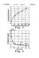
- the resultsare shown in FIG. 4 along with the other operating parameters.
- the initial permeate fluxwas very high at 300 gfd, but after two hours, it had dropped to only 37 gfd (gallons/ft 2 /day)(factor of eight).
- the first data point shown in FIG. 4was taken immediately after exposing the clean membrane to the feed.
- This figureshows a sharp decrease in the permeate flux early in the run followed by a slower decrease (i.e., leveling off) in the permeate flux as the run continued.
- the initially sharp decrease in permeate fluxis typical of cross-flow filtration processes and is usually attributed to the buildup of particles at the surface of the membrane in contact with the feed.
- the permeate fluxlevels off with time as the layer of retained solids reaches a constant thickness. If particle accumulation at the membrane surface were responsible for the decline in permeate flux, then backflushing should have temporarily increased the permeate flux.
- FIG. 4shows a sharp decrease in the permeate flux early in the run followed by a slower decrease (i.e., leveling off) in the permeate flux as the run continued.
- the initially sharp decrease in permeate fluxis typical of cross-flow filtration processes and is usually attributed to the buildup of particles at the surface of the membrane in contact
- Table IIIThe results shown in Table III indicate that the 500 Angstrom membrane was able to produce a solids-free permeate during all runs, and that by removing permeate from the system rather than returning it to the feed tank, it was possible to concentrate Q.I. particles in the feed stream.
- This Table IIIalso shows the effect of various operating conditions on the permeation flux. For example, a comparison between run 3-GLG-X-13 and 3-GLG-X-14 indicates that an increase in the feed flow rate results in an increased permeation flux across the membrane. This result is expected since high flow rates result in a thinner filter cake at the membrane surface.
- the flux measured for the tar (A)/toluene mixturehas a value of 25.5 gfd and since the tar constitutes 50 wt % of the mixture, the flux of tar (A) is about half of the total flux. Thus, higher fluxes of coal tar are obtained when the feed is diluted.
- the method of the inventionis operable with tar having a viscosity as high as 500 cps; a preferred tar viscosity for increased through put is 50 cps or less.
- tarhaving a viscosity as high as 500 cps; a preferred tar viscosity for increased through put is 50 cps or less.
- Such lower viscositiesare obtainable by heating the tar to a suitable temperature suitable for the particular tar; alternatively a solvent can be added to the tar, as disclosed herein, in amounts of 20 to 80% by weight.
- a schematic for a continuous-operation Q.I. particle filtration and concentration unit for processing Q.I. containing liquid taris shown at 100.
- the unit 100comprises a pre-heater 102 which contains Q.I. containing tar feed material 104.
- the tar feed material 104is heated to a temperature in the range of 80°-320° C. in order to reduce the viscosity to a minimum value without the occurrence of volatilization or chemical reaction in the tar (see Example I for tar (A) and tar (B)).
- the particular temperature for minimum viscosity for different tarswill vary and is determined by routine measurement.
- tar feed 104is moved by pump 108 and mass flow controller 110 into circulation loop 112 through loop inlet 114.
- the fresh Q.I. containing tar feed thus introduced into circulation loop 112passes by way of conduit 111 into the inlet 129 of membrane filter 115 and a Q.I. free liquid tar permeate 116 exits filter 115 at 118, and the Q.I. containing concentrate exits the membrane filter 115 at 125.
- free liquid tar permeate flow rateis established by regulation of mass flow controller 120 while correspondingly adjusting the flow of tar feed into circulation loop 112 at 114 so that the amount (quantity) of tar being circulated in loop 112 remains substantially constant while being repeatedly circulated as shown at 113 at a high rate of flow in loop 112, by high pressure pump 122 in conjunction with mass flow controller 123.
- concentration of Q.I. in this circulating liquid taris increased due to permeate removal from loop 112.
- valve 124is opened and liquid tar concentrate 128, i.e. tar of higher Q.I.
- the Q.I. concentration in the liquid tar circulating in the portion of loop 112 between the exit 125 of filter 115 and feed inlet 114, C 1is the same as the Q.I. concentration, C c , in the liquid tar concentrate 128.
- the flow of liquid tar concentrate (high "Q.I.") 128is regulated at mass flow controller 130 and the amount of tar feed introduced at 114 into circulation loop 112 before filter 115 is correspondingly increased.
- F pthe flow rate at which Q.I. free permeate (116) exits filter and circulation loop
- Example 6will serve to further illustrate the preferred embodiment of FIG. 7.
- FIG. 7A continuous microfiltration plant for Q.I. concentration in liquid tar and concurrent production of Q.I. free tar is shown in FIG. 7 at 100.
- Ceramic. membrane filter 115(U.S. Filter) is housed inside a stainless-steel case and has a nominal pore diameter of 500 angstrom and a total surface area of 75 ft 2 .
- the fresh feed of coal tar 104is preheated to between 80° and 350° C. to minimize viscosity and pumped into the "circulation" process loop 112 which includes a large WAUKESHA positive displacement pump 122, the U.S. Filter ceramic membrane module 115 and a MICRO MOTION mass flow controller 123.
- the temperature of the circulation process loopis likewise maintained at the minimum viscosity temperature between 80° and 320° C. using hot oil tracing.
- the flow rates of fresh feed 104, permeate 116, concentrate 128, and recirculation 113are respectively regulated by MICRO MOTION mass flow controllers 110, 120, 130, and 123.
- the flow rates of fresh feed 104 and concentrate 128are controlled according to the initial Q.I. level in the fresh coal tar feed 104, the desired Q.I. level of the concentrate 128, and the flow rate of permeate 116.
- the flow rate of coal tar 111 inside the circulation loop 112is maintained very high, 10 2 -10 4 times the flow rate of the fresh feed 104, in order to create and maintain a turbulent flow inside the tubular ceramic membrane.
- a material balance of the system with permeate from the membrane filter being Q.I. freegives the following:
- F f , F p , and F cdenote the respective flow rates of the fresh feed, permeate, and concentrate and C f , C p and C c denote the solid wt. % correspondingly.
- C pis equal to zero; i.e., the permeate is Q.I. free.
- the filtration ratei.e., the permeation flux
- the permeation fluxis approximately 10 gallon/ft 2 /day (gfd) for filtering a undiluted coal tar (B) with the use of a 500-Angstrom membrane.
- the steady-state permeation flow rate, F pis determined as follows:
- concentrating the tar to contain 3, 4, and 5 wt. % Q.I. solidscan be achieved by operating the system according to the following sets of conditions:
- valve 124is opened and tar concentrate is withdrawn from circulation loop 112 at the rate F c corresponding to the desired Q.I. concentration C c by operation of mass flow controller 130; concurrently, the fresh feed flow rate F f is increased by amount of withdrawn tar concentrate, F c .
Landscapes
- Engineering & Computer Science (AREA)
- Water Supply & Treatment (AREA)
- Chemical & Material Sciences (AREA)
- Chemical Kinetics & Catalysis (AREA)
- Oil, Petroleum & Natural Gas (AREA)
- Materials Engineering (AREA)
- Organic Chemistry (AREA)
- Separation Using Semi-Permeable Membranes (AREA)
Abstract
Description
TABLE I ______________________________________ Data for FIG. 4 Perm Time Temp Pressure (psig) Flux (mins) Backflush (C.) Inlet Outlet (gfd) ______________________________________ 0 72 40 30 296.6 12 80 40 33 187.2 22 79 40 33 107.1 37 79 40 33 70.1 62 80 40 33 53.5 92 80 40 33 39.9 122 80 40 33 37.3 137 80 40 33 51.4 167 80 40 33 34.3 197 80 40 33 25.7 204 79 40 33 26.6 234 80 40 33 23.4 ______________________________________ Feed: 50 wt % Coal Tar (B), 50 wt % Toluene Feed Flow Rate: 3.9 gpm
TABLE II ______________________________________ Data for FIG. 5 Perm Perm Time Temp Pressure (psig) Flux QI (mins) Backflush (C.) Inlet Outlet (gfd) wt % ______________________________________ 0 82 40 34 771.1 15 81 40 36 275.4 35 80 40 36 142.8 0 65 80 40 36 66.0 95 80 40 36 53.6 100 80 40 35 419.1 0 140 80 40 36 68.9 0 170 80 40 35 47.0 200 80 40 35 44.8 0 205 80 40 35 428.4 245 80 40 36 60.2 0 ______________________________________ Feed: 50 wt % Coal Tar (A), 50 wt % Toluene Feed Flow Rate: 3.0 gpm
TABLE III __________________________________________________________________________Summary of Results for the Filtration of Undiluted Tar (B) with a 500 Angstrom Membrane Pressure Flow Perm Temp (psig) Rate Flux Q. I. Content (wt %) Run (C.) Inlet Outlet (gpm) (gfd) Feed Permeate __________________________________________________________________________3-GLG-X-12 80 40 27 4.9 5.6 5.0 0 3-GLG-X-13 90 60 46 5.2 9.0 5.0 0 3-GLG-X-14 90 60 30 7.7 13.2 5.0 0 3-GLG-X-17a 90 60 30 7.7 11.9 5.1 0 3-GLG-X-17b 90 60 30 7.7 10.5 5.2 0 3-GLG-X-18 90 60 30 7.7 8.2 5.8 0 __________________________________________________________________________
TABLE IV __________________________________________________________________________Summary of Results for the Filtration of Undiluted Tar (A) with a 500 Angstrom Membrane Flow Perm Temp Pressure (psig) Rate Flux Q. I. Content (wt %) Run Feed (C.) Inlet Outlet (gpm) (gfd) Feed Permeate __________________________________________________________________________3-GLG-X-49 Tar (A) 110 60 30 5.9 1.8 2.4 0 3-GLG-X-50a Tar (A) 110 60 30 5.9 1.4 2.4 0 3-GLG-X-50b Tar (A) 110 60 30 5.9 1.1 2.4 0 3-GLG-X-19 50/50 80 40 32 4.0 25.5 1.2 0 Tar (A)/ Toluene 3-GLG-X-14, Tar (B) 90 60 30 7.7 8 to 14 5 0 15, 16, 17, 18 __________________________________________________________________________
F.sub.f =F.sub.p +F.sub.c (1)
F.sub.f ×C.sub.f =F.sub.p ×C.sub.p +F.sub.c ×C.sub.c =F.sub.c ×C.sub.c (C.sub.p =O) (2)
______________________________________ C.sub.c = Solid wt. % in the Concentrate C.sub.f = 1wt. % 3 wt. % 4wt. % 5 wt. % ______________________________________ Fresh Feed Rate, 46.9 41.7 39.1 Gallons/Hr. - F.sub.f Permeate Rate, 31.3 31.3 31.3 Gallons/Hr. - F.sub.p Concentrate Rate, 15.6 10.4 7.8 Gallons/Hr. - F.sub.c ______________________________________
______________________________________ C.sub.c = Solid wt. % in the Concentrate C.sub.f = 1.5wt. % 3 wt. % 4wt. % 5 wt. % ______________________________________ Fresh Feed Rate, 62.6 50.0 44.7 Gallons/Hr. - F.sub.f Permeate Rate, 31.3 31.3 31.3 Gallons/Hr. - F.sub.p Concentrate Rate, 31.3 18.7 13.4 Gallons/Hr. - F.sub.c ______________________________________
Claims (5)
Priority Applications (4)
| Application Number | Priority Date | Filing Date | Title |
|---|---|---|---|
| US08/341,395US5534133A (en) | 1994-11-17 | 1994-11-17 | Continuous method for increasing the Q. I. concentration of liquid tar while concurrently producing a Q. I. free tar |
| DE69511045TDE69511045T2 (en) | 1994-11-17 | 1995-11-16 | Continuous process for increasing Quinoline's insoluble concentration of a liquid tar while simultaneously producing a Quinoline-insoluble free tar |
| EP95308207AEP0712921B1 (en) | 1994-11-17 | 1995-11-16 | Continuous method for increasing the quinoline insoluble concentration of liquid tar while concurrently producing a quinoline insoluble free tar |
| ES95308207TES2133680T3 (en) | 1994-11-17 | 1995-11-16 | CONTINUOUS METHOD FOR INCREASING THE CONCENTRATION IN INSOLUBLES IN LIQUID TAR QUINOLINE WHILE IT IS PRODUCED SIMULTANEOUSLY WITH QUINOLINE-FREE INSOLUBLE TAR. |
Applications Claiming Priority (1)
| Application Number | Priority Date | Filing Date | Title |
|---|---|---|---|
| US08/341,395US5534133A (en) | 1994-11-17 | 1994-11-17 | Continuous method for increasing the Q. I. concentration of liquid tar while concurrently producing a Q. I. free tar |
Publications (1)
| Publication Number | Publication Date |
|---|---|
| US5534133Atrue US5534133A (en) | 1996-07-09 |
Family
ID=23337366
Family Applications (1)
| Application Number | Title | Priority Date | Filing Date |
|---|---|---|---|
| US08/341,395Expired - Fee RelatedUS5534133A (en) | 1994-11-17 | 1994-11-17 | Continuous method for increasing the Q. I. concentration of liquid tar while concurrently producing a Q. I. free tar |
Country Status (4)
| Country | Link |
|---|---|
| US (1) | US5534133A (en) |
| EP (1) | EP0712921B1 (en) |
| DE (1) | DE69511045T2 (en) |
| ES (1) | ES2133680T3 (en) |
Cited By (8)
| Publication number | Priority date | Publication date | Assignee | Title |
|---|---|---|---|---|
| WO1998013439A1 (en)* | 1996-09-27 | 1998-04-02 | Ucar Carbon Technology Corporation | Method of production of solids-free coal tar pitch |
| US20020185411A1 (en)* | 2001-05-11 | 2002-12-12 | Saver William E. | Coal tar and hydrocarbon mixture pitch production using a high efficiency evaporative distillation process |
| US20020197851A1 (en)* | 2000-12-29 | 2002-12-26 | Ilan Gavish | Focused ion beam deposition |
| US20030106836A1 (en)* | 2001-12-10 | 2003-06-12 | Orac Thomas H. | Batch process for making high flash point pitch |
| US20040208833A1 (en)* | 2003-02-04 | 2004-10-21 | Elan Pharma International Ltd. | Novel fluticasone formulations |
| US20050252453A1 (en)* | 2000-12-29 | 2005-11-17 | Dan Gavish | Apparatus and a method for forming an alloy layer over a substrate |
| US20060051508A1 (en)* | 2000-12-28 | 2006-03-09 | Ilan Gavish | Focused ion beam deposition |
| US11248172B2 (en) | 2019-07-23 | 2022-02-15 | Koppers Delaware, Inc. | Heat treatment process and system for increased pitch yields |
Citations (10)
| Publication number | Priority date | Publication date | Assignee | Title |
|---|---|---|---|---|
| US2956944A (en)* | 1958-02-10 | 1960-10-18 | Allied Chem | Process for filtering tar |
| US3173851A (en)* | 1960-07-26 | 1965-03-16 | Exxon Research Engineering Co | Electrode pitch binders |
| US4127472A (en)* | 1976-11-26 | 1978-11-28 | Nittetsu Chemical Industrial Co., Ltd. | Process for preparing a raw material for the manufacture of needle coke |
| US4177132A (en)* | 1976-11-12 | 1979-12-04 | Nippon Oil Company, Ltd. | Process for the continuous production of petroleum-derived pitch |
| US4183802A (en)* | 1976-04-03 | 1980-01-15 | Bergwerksverband Gmbh | Process for the production of coke from pitch |
| US4259171A (en)* | 1978-03-10 | 1981-03-31 | Rutgerswerke Aktiengesellschaft | Process for the separation of quinoline-insoluble components from coal tar pitch |
| US4333816A (en)* | 1980-02-22 | 1982-06-08 | Bergwerksverband Gmbh | Method for the production of needle coke |
| US4436615A (en)* | 1983-05-09 | 1984-03-13 | United States Steel Corporation | Process for removing solids from coal tar |
| US4604184A (en)* | 1983-11-16 | 1986-08-05 | Domtar Inc. | Modified coal-tar pitch |
| US4954240A (en)* | 1987-09-16 | 1990-09-04 | Exxon Research & Engineering Company | Combination coking and hydroconversion process |
Family Cites Families (8)
| Publication number | Priority date | Publication date | Assignee | Title |
|---|---|---|---|---|
| FR1128491A (en)* | 1954-04-16 | 1957-01-07 | Koppers Co Inc | Improvements in processes to reduce the content of c1 carbon particles in tar |
| FR2482975A1 (en)* | 1980-05-22 | 1981-11-27 | Commissariat Energie Atomique | PROCESS FOR TREATING ULTRAFILTRATION AT HIGH TEMPERATURE OF A HYDROCARBONATED LOAD |
| DE3305431A1 (en)* | 1983-02-17 | 1984-08-23 | Bergwerksverband Gmbh, 4300 Essen | METHOD FOR CLEANING HIGH-SOLID COOKER TARS |
| CA1263845A (en)* | 1985-08-28 | 1989-12-12 | Oleh Kutowy | Method of removing substances from fossil derived, hydrocarbon liquids |
| HU200563B (en)* | 1987-03-06 | 1990-07-28 | Laszlo Szuecs | Method and apparatus for treating liquids consist of foreign matter by diaphragm filter device |
| JPH03166290A (en)* | 1989-11-24 | 1991-07-18 | Toho Gas Co Ltd | Method for refining coal tar and coal tar pitch |
| DE4126483A1 (en)* | 1991-08-10 | 1993-02-11 | Bayer Ag | METHOD FOR CONCENTRATING LATEX DISPERSIONS |
| US5242597A (en)* | 1992-07-24 | 1993-09-07 | Eastman Kodak Company | Fixed cycle time ultrafiltration process |
- 1994
- 1994-11-17USUS08/341,395patent/US5534133A/ennot_activeExpired - Fee Related
- 1995
- 1995-11-16EPEP95308207Apatent/EP0712921B1/ennot_activeExpired - Lifetime
- 1995-11-16DEDE69511045Tpatent/DE69511045T2/ennot_activeExpired - Fee Related
- 1995-11-16ESES95308207Tpatent/ES2133680T3/ennot_activeExpired - Lifetime
Patent Citations (10)
| Publication number | Priority date | Publication date | Assignee | Title |
|---|---|---|---|---|
| US2956944A (en)* | 1958-02-10 | 1960-10-18 | Allied Chem | Process for filtering tar |
| US3173851A (en)* | 1960-07-26 | 1965-03-16 | Exxon Research Engineering Co | Electrode pitch binders |
| US4183802A (en)* | 1976-04-03 | 1980-01-15 | Bergwerksverband Gmbh | Process for the production of coke from pitch |
| US4177132A (en)* | 1976-11-12 | 1979-12-04 | Nippon Oil Company, Ltd. | Process for the continuous production of petroleum-derived pitch |
| US4127472A (en)* | 1976-11-26 | 1978-11-28 | Nittetsu Chemical Industrial Co., Ltd. | Process for preparing a raw material for the manufacture of needle coke |
| US4259171A (en)* | 1978-03-10 | 1981-03-31 | Rutgerswerke Aktiengesellschaft | Process for the separation of quinoline-insoluble components from coal tar pitch |
| US4333816A (en)* | 1980-02-22 | 1982-06-08 | Bergwerksverband Gmbh | Method for the production of needle coke |
| US4436615A (en)* | 1983-05-09 | 1984-03-13 | United States Steel Corporation | Process for removing solids from coal tar |
| US4604184A (en)* | 1983-11-16 | 1986-08-05 | Domtar Inc. | Modified coal-tar pitch |
| US4954240A (en)* | 1987-09-16 | 1990-09-04 | Exxon Research & Engineering Company | Combination coking and hydroconversion process |
Non-Patent Citations (4)
| Title |
|---|
| H. A. Kremer, Chemistry and Industry, pp. 702 713, Sep. 18, 1982, Recent Developments in Electrode Pitch and Coal Tar Technology .* |
| H. A. Kremer, Chemistry and Industry, pp. 702-713, Sep. 18, 1982, "Recent Developments in Electrode Pitch and Coal Tar Technology". |
| K. Kai 3(1991) 166,290 Toho Gas, Method for the Purification of Coal Tar and Coal Tar Pitch .* |
| K. Kai 3(1991) 166,290-Toho Gas, "Method for the Purification of Coal Tar and Coal Tar Pitch". |
Cited By (19)
| Publication number | Priority date | Publication date | Assignee | Title |
|---|---|---|---|---|
| US5843298A (en)* | 1996-09-27 | 1998-12-01 | Ucar Carbon Technology Corporation | Method of production of solids-free coal tar pitch |
| WO1998013439A1 (en)* | 1996-09-27 | 1998-04-02 | Ucar Carbon Technology Corporation | Method of production of solids-free coal tar pitch |
| US20060051508A1 (en)* | 2000-12-28 | 2006-03-09 | Ilan Gavish | Focused ion beam deposition |
| US20050252453A1 (en)* | 2000-12-29 | 2005-11-17 | Dan Gavish | Apparatus and a method for forming an alloy layer over a substrate |
| US20060252255A9 (en)* | 2000-12-29 | 2006-11-09 | Ilan Gavish | Focused ion beam deposition |
| US20020197851A1 (en)* | 2000-12-29 | 2002-12-26 | Ilan Gavish | Focused ion beam deposition |
| US20060051950A1 (en)* | 2000-12-29 | 2006-03-09 | Iian Gavish | Apparatus and a method for forming an alloy layer over a substrate |
| US7033485B2 (en) | 2001-05-11 | 2006-04-25 | Koppers Industries Of Delaware, Inc. | Coal tar and hydrocarbon mixture pitch production using a high efficiency evaporative distillation process |
| US20050081752A1 (en)* | 2001-05-11 | 2005-04-21 | Snyder David R. | Chopped carbon fiber preform processing method using coal tar pitch binder |
| US20050263436A1 (en)* | 2001-05-11 | 2005-12-01 | Saver William E | Coal tar and hydrocarbon mixture pitch production using a high efficiency evaporative distillation process |
| US20040168612A1 (en)* | 2001-05-11 | 2004-09-02 | Saver William E | Coal tar and hydrocarbon mixture pitch and the preparation and use thereof |
| US7066997B2 (en) | 2001-05-11 | 2006-06-27 | Koppers Delaware, Inc. | Coal tar and hydrocarbon mixture pitch and the preparation and use thereof |
| US20060230982A1 (en)* | 2001-05-11 | 2006-10-19 | Golubic Thomas A | Coal tar and hydrocarbon mixture pitch and the preparation and use thereof |
| US20020185411A1 (en)* | 2001-05-11 | 2002-12-12 | Saver William E. | Coal tar and hydrocarbon mixture pitch production using a high efficiency evaporative distillation process |
| US7465387B2 (en) | 2001-05-11 | 2008-12-16 | Koppers Delaware, Inc. | Coal tar and hydrocarbon mixture pitch and the preparation and use thereof |
| US20030106836A1 (en)* | 2001-12-10 | 2003-06-12 | Orac Thomas H. | Batch process for making high flash point pitch |
| US20040208833A1 (en)* | 2003-02-04 | 2004-10-21 | Elan Pharma International Ltd. | Novel fluticasone formulations |
| US11248172B2 (en) | 2019-07-23 | 2022-02-15 | Koppers Delaware, Inc. | Heat treatment process and system for increased pitch yields |
| US11624029B2 (en) | 2019-07-23 | 2023-04-11 | Koppers Delaware, Inc. | Heat treatment process for increased pitch yields |
Also Published As
| Publication number | Publication date |
|---|---|
| DE69511045D1 (en) | 1999-09-02 |
| EP0712921B1 (en) | 1999-07-28 |
| DE69511045T2 (en) | 2000-02-17 |
| ES2133680T3 (en) | 1999-09-16 |
| EP0712921A1 (en) | 1996-05-22 |
Similar Documents
| Publication | Publication Date | Title |
|---|---|---|
| US5534133A (en) | Continuous method for increasing the Q. I. concentration of liquid tar while concurrently producing a Q. I. free tar | |
| DE3885527T2 (en) | Permeable gas separation membranes. | |
| DE19646094C2 (en) | Process for chemical gas phase infiltration of refractory substances, in particular carbon and silicon carbide, and use of the process | |
| Pan et al. | Fabrication of carbon membrane and microfiltration of oil-in-water emulsion: an investigation on fouling mechanisms | |
| DE1115023B (en) | Method and device for activating or regenerating a chromium oxide-containing olefin polymerization catalyst | |
| US5843298A (en) | Method of production of solids-free coal tar pitch | |
| EP1375707A1 (en) | Activated carbon fibres and their production process | |
| DE69013027T2 (en) | Process for the preparation of a polyimide ultrafiltration membrane and its use for the recovery of a dewaxing aid. | |
| DE69730706T2 (en) | DEGRADATION OF LUBRICATING OILS BY MEMBRANE SEPARATION | |
| JPH0275329A (en) | Method for lowering cloud point of substance using ultrafiltration separation method | |
| Russotti et al. | Pilot-scale harvest of recombinant yeast employing microfiltration: a case study | |
| JP2935822B2 (en) | A continuous process for increasing the concentration of insoluble solids in liquid tars while simultaneously producing tars without insoluble solids | |
| US4606903A (en) | Membrane separation of uncoverted carbon fiber precursors from flux solvent and/or anti-solvent | |
| US2775550A (en) | Reduction of c1 carbon content in tar | |
| CN112852464A (en) | Pretreatment method of raw oil for preparing spinnable mesophase pitch and high-performance pitch-based carbon fiber | |
| DD279907A5 (en) | METHOD AND DEVICE FOR PRODUCING CARBON FIBERS | |
| EP1706196B1 (en) | Membrane production method | |
| DE3905531A1 (en) | METHOD FOR PRODUCING AN IMPREGNATED CERAMIC MATERIAL | |
| JPH01101392A (en) | Single flow solid recerculation coking method | |
| EP0150223B1 (en) | Process for manufacturing carbon fiber and graphite fiber | |
| US4976845A (en) | Process for increasing meso phase contents in pitch | |
| DE4217328C1 (en) | Diamond layer CVD appts. - has closed gas circuit contg. carbon reactor for process gas regeneration | |
| DE2116840B2 (en) | Process for the production of highly oriented, anisotropic, essentially monocrystalline graphite particles | |
| EP2539043A1 (en) | Method for separating components of natural gas or petroleum gas using inorganic porous membranes | |
| DE3300673A1 (en) | METHOD AND DEVICE FOR THE PYROLYTIC DECOMPOSITION OF POLYMERS |
Legal Events
| Date | Code | Title | Description |
|---|---|---|---|
| AS | Assignment | Owner name:UCAR CARBON TECHNOLOGY CORPORATION, CONNECTICUT Free format text:ASSIGNMENT OF ASSIGNORS INTEREST;ASSIGNORS:LEWIS, IRVIN W.;CHANG, CHING-FENG;KELLER, GEORGE E. II;AND OTHERS;REEL/FRAME:007323/0902;SIGNING DATES FROM 19941018 TO 19941111 | |
| AS | Assignment | Owner name:CHEMICAL BANK, AS COLLATERAL AGENT ATTN: THEODORE Free format text:SECURITY INTEREST;ASSIGNORS:UCAR CARBON COMPANY INC.;UCAR GLOBAL ENTERPRISES INC.;UCAR CARBON TECHNOLOGY CORPORATION;AND OTHERS;REEL/FRAME:007439/0001 Effective date:19950126 | |
| AS | Assignment | Owner name:CHASE MANHATTAN BANK, THE, NEW YORK Free format text:SECURITY AGREEMENT;ASSIGNOR:UCAR CARBON TECHNOLOGY CORPORATION;REEL/FRAME:009214/0001 Effective date:19980422 | |
| AS | Assignment | Owner name:CHASE MANHATTAN BANK, THE, AS COLLATERAL AGENT, NE Free format text:SECURITY AGREEMENT;ASSIGNOR:UCAR CARBON TECHNOLOGY CORP.;REEL/FRAME:009633/0001 Effective date:19981110 | |
| FEPP | Fee payment procedure | Free format text:PAYOR NUMBER ASSIGNED (ORIGINAL EVENT CODE: ASPN); ENTITY STATUS OF PATENT OWNER: LARGE ENTITY | |
| FPAY | Fee payment | Year of fee payment:4 | |
| AS | Assignment | Owner name:UCAR CARBON COMPANY INC., TENNESSEE Free format text:ASSIGNMENT OF ASSIGNORS INTEREST;ASSIGNOR:UCAR CARBON TECHNOLOGY CORPORATION;REEL/FRAME:010609/0001 Effective date:19991231 | |
| AS | Assignment | Owner name:MORGAN GUARANTY TRUST COMPANY OF NEW YORK, AS COLL Free format text:SECURITY AGREEMENT;ASSIGNOR:UCAR CARBON COMPANY, INC.;REEL/FRAME:010668/0783 Effective date:20000222 | |
| AS | Assignment | Owner name:UCAR CARBON TECHNOLOGY CORP., CONNECTICUT Free format text:INTELLECTUAL PROPERTY RELEASE;ASSIGNOR:CHASE MANHATTAN BANK, THE, AS COLLATERAL AGENT;REEL/FRAME:010937/0245 Effective date:20000222 | |
| FPAY | Fee payment | Year of fee payment:8 | |
| AS | Assignment | Owner name:JPMORGAN CHASE BANK, N.A., AS COLLATERAL AGENT, TE Free format text:SECURITY AGREEMENT;ASSIGNOR:UCAR CARBON COMPANY INC.;REEL/FRAME:015878/0445 Effective date:20050208 | |
| REMI | Maintenance fee reminder mailed | ||
| LAPS | Lapse for failure to pay maintenance fees | ||
| LAPS | Lapse for failure to pay maintenance fees | Free format text:PATENT EXPIRED FOR FAILURE TO PAY MAINTENANCE FEES (ORIGINAL EVENT CODE: EXP.); ENTITY STATUS OF PATENT OWNER: LARGE ENTITY | |
| STCH | Information on status: patent discontinuation | Free format text:PATENT EXPIRED DUE TO NONPAYMENT OF MAINTENANCE FEES UNDER 37 CFR 1.362 | |
| FP | Lapsed due to failure to pay maintenance fee | Effective date:20080709 | |
| AS | Assignment | Owner name:GRAFTECH INTERNATIONAL HOLDINGS INC. (F/K/A AS UCAR CARBON COMPANY INC.), OHIO Free format text:CORRECTIVE ASSIGNMENT TO CORRECT THE PATENT NUMBERS PREVIOUSLY RECORDED AT REEL: 70291 FRAME: 686. ASSIGNOR(S) HEREBY CONFIRMS THE RELEASE OF SECURITY INTEREST;ASSIGNOR:JPMORGAN CHASE BANK, N.A.;REEL/FRAME:071632/0215 Effective date:20250220 |