US5534104A - Method and apparatus for production of three-dimensional objects - Google Patents
Method and apparatus for production of three-dimensional objectsDownload PDFInfo
- Publication number
- US5534104A US5534104AUS08/244,498US24449894AUS5534104AUS 5534104 AUS5534104 AUS 5534104AUS 24449894 AUS24449894 AUS 24449894AUS 5534104 AUS5534104 AUS 5534104A
- Authority
- US
- United States
- Prior art keywords
- regions
- partial regions
- solidifying
- layer
- partial
- Prior art date
- Legal status (The legal status is an assumption and is not a legal conclusion. Google has not performed a legal analysis and makes no representation as to the accuracy of the status listed.)
- Expired - Fee Related
Links
Images

Classifications
- B—PERFORMING OPERATIONS; TRANSPORTING
- B29—WORKING OF PLASTICS; WORKING OF SUBSTANCES IN A PLASTIC STATE IN GENERAL
- B29C—SHAPING OR JOINING OF PLASTICS; SHAPING OF MATERIAL IN A PLASTIC STATE, NOT OTHERWISE PROVIDED FOR; AFTER-TREATMENT OF THE SHAPED PRODUCTS, e.g. REPAIRING
- B29C64/00—Additive manufacturing, i.e. manufacturing of three-dimensional [3D] objects by additive deposition, additive agglomeration or additive layering, e.g. by 3D printing, stereolithography or selective laser sintering
- B29C64/40—Structures for supporting 3D objects during manufacture and intended to be sacrificed after completion thereof
- B—PERFORMING OPERATIONS; TRANSPORTING
- B29—WORKING OF PLASTICS; WORKING OF SUBSTANCES IN A PLASTIC STATE IN GENERAL
- B29C—SHAPING OR JOINING OF PLASTICS; SHAPING OF MATERIAL IN A PLASTIC STATE, NOT OTHERWISE PROVIDED FOR; AFTER-TREATMENT OF THE SHAPED PRODUCTS, e.g. REPAIRING
- B29C64/00—Additive manufacturing, i.e. manufacturing of three-dimensional [3D] objects by additive deposition, additive agglomeration or additive layering, e.g. by 3D printing, stereolithography or selective laser sintering
- B29C64/10—Processes of additive manufacturing
- B29C64/106—Processes of additive manufacturing using only liquids or viscous materials, e.g. depositing a continuous bead of viscous material
- B29C64/124—Processes of additive manufacturing using only liquids or viscous materials, e.g. depositing a continuous bead of viscous material using layers of liquid which are selectively solidified
- B29C64/129—Processes of additive manufacturing using only liquids or viscous materials, e.g. depositing a continuous bead of viscous material using layers of liquid which are selectively solidified characterised by the energy source therefor, e.g. by global irradiation combined with a mask
- B29C64/135—Processes of additive manufacturing using only liquids or viscous materials, e.g. depositing a continuous bead of viscous material using layers of liquid which are selectively solidified characterised by the energy source therefor, e.g. by global irradiation combined with a mask the energy source being concentrated, e.g. scanning lasers or focused light sources
- B—PERFORMING OPERATIONS; TRANSPORTING
- B29—WORKING OF PLASTICS; WORKING OF SUBSTANCES IN A PLASTIC STATE IN GENERAL
- B29C—SHAPING OR JOINING OF PLASTICS; SHAPING OF MATERIAL IN A PLASTIC STATE, NOT OTHERWISE PROVIDED FOR; AFTER-TREATMENT OF THE SHAPED PRODUCTS, e.g. REPAIRING
- B29C37/00—Component parts, details, accessories or auxiliary operations, not covered by group B29C33/00 or B29C35/00
- B29C37/005—Compensating volume or shape change during moulding, in general
- Y—GENERAL TAGGING OF NEW TECHNOLOGICAL DEVELOPMENTS; GENERAL TAGGING OF CROSS-SECTIONAL TECHNOLOGIES SPANNING OVER SEVERAL SECTIONS OF THE IPC; TECHNICAL SUBJECTS COVERED BY FORMER USPC CROSS-REFERENCE ART COLLECTIONS [XRACs] AND DIGESTS
- Y10—TECHNICAL SUBJECTS COVERED BY FORMER USPC
- Y10S—TECHNICAL SUBJECTS COVERED BY FORMER USPC CROSS-REFERENCE ART COLLECTIONS [XRACs] AND DIGESTS
- Y10S264/00—Plastic and nonmetallic article shaping or treating: processes
- Y10S264/59—Processes in which a partial cure is involved
Definitions
- the inventionrelates to a method and to an apparatus for production of three-dimensional objects.
- EP-A-0,362,982proposes either to begin with solidifying individual strips only which are connected to adjacent or underlying strips only by means of a support structure or to solidify only regions of the layer whereby gaps are generated between those regions.
- this objectis achieved by a method characterized in claim 1 and by the apparatus characterized in claim 11, resp.
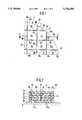
- FIG. 1is a top view of a layer of an object solidified according to the invention
- FIG. 2is a sectional view of the object taken along the line II--II of FIG. 1;
- FIG. 3is a schematic representation of an embodiment of the inventive apparatus.
- FIG. 1is a top view of a part of an object 1 of which a section is shown in FIG. 2.
- the objectis produced in the form of individual superposed layers 2a, 2b, 2c, 2d and 2e for example by subsequent solidification of the layers on a support 3 in a bath of liquid resin which can be polymerized by action of electromagnetic radiation. Such a method is known and a detailed description thereof is therefore omitted at this place.
- the first layer 2a adjacent to the support 3is produced in a known manner by complete solidification of the layer within the contour or boundary surface 5 of the object.
- FIG. 1shows the top view of the top face 4 of the uppermost layer 2e which is outwardly defined by the contour 5 of the object 1.
- the respective further layers 2b . . . 2eare produced according to the same rules and the production of those layers of the object is therefore described in the following by reference to the top view of layer 2e shown in FIG. 1.
- First of all a liquid layer formed on the first layer 2ais not solidified everywhere within the contour 5 but only at partial regions 6a . . . 6k spaced from each other at all sides.
- Those partial regionsare shown in FIG. 1 as being substantially square-shaped but may have any other shape.
- the size of the partial regionsis free but preferably a linear dimension of 1-20 mm, in particular 2-10 mm is chosen.
- the width of those intermediate regionsi.e. the clearance between the partial regions 6a . . . 6k, is about 1/20 to 1/500, preferably about 1/50 to 1/200 and particularly preferred about 1/100 of the dimension of the partial regions, i.e. about 0.05 to 0.2 mm, preferably about 0.1 mm.
- the partial regions shrink during and after the solidification and the width of the intermediate regions 7is thereby enlarged.
- the shrinkage rateis particularly high in the first seconds after the irradiation and for example about 80% of the shrinkage occurs within 10 seconds. Considering the conventional production speed this shrinkage rate means that the shrinkage of the first solidified partial regions of the layer 2b has already terminated to a large extent when solidifying the last partial regions.
- connecting regions in the form of thin connecting webs 8a . . . 8p connecting respective adjacent partial regions 6a, 6b; 6b, 6c; 6b; 6e; etc.are solidified.
- the width of those connecting websis in the order of about 1/50 to 1/200 and preferably about 1/100 of the dimension of the partial regions, i.e. about 0.05 to 0.2 mm, preferably about 0.1 mm.
- One or more connecting websmay be formed between two adjacent partial regions.
- the contour 5 boundary regions 9a . . . 9fare formed which either replace the connecting regions of the partial regions 6a, 6c, 6g, 6k adjacent to the contour or are formed in addition to those connecting regions.
- the connecting webs 8a . . . 8p and the boundary regions 9a . . . 9fare preferably solidified after the shrinkage of the partial regions 6a . . . 6k, because the forces acting on the connecting webs and therefore the stresses and deformations of the webs are reduced in this case. Formation of the connecting webs therefore preferably starts between those partial regions of a layer which were solidified first and thus have the most advanced shrinkage. Alternatively, the webs may, however, also be solidified simultaneously with the solidification of the respective adjacent partial regions. In any case the purpose of the connecting webs is to interconnect the partial regions 6a . . . 6k and thus to retain the geometric structure and the mechanical stability.
- each partial regionis connected with the underlying partial regions so that individual cells 11a, 11b etc. in the form of vertical prismatic elements are generated which are interconnected by the superposed connecting regions 8 forming vertical ribs.
- the (not shown) uppermost layer of the object 1is formed in the same manner as the first layer 2a, i.e. as completely solidified layer. Hence, a closed rigid shell or surface of the object 1 is formed by the uppermost layer, the first layer 2a and the boundary regions 9 and remaining liquid material within the gaps 10 can not flow out when withdrawing the object from the bath. This liquid material is subsequently solidified by post-curing under the influence of radiation or heat.
- each partial region 6Owing to the solidification of each partial region 6 separate from adjacent partial regions the shrinkage is locally defined. Due to the timely shifted solidification of the connecting regions 8 stresses and deformations are low and are mainly received by the connecting regions whereby the deformation of the entire object is considerably reduced. Owing to the small width of the gaps 10 formed by the narrow intermediate regions 7 the shrinkage occurring when later solidifying the material within those gaps causes an insignificant deformation only. Finally, the specific radiation power used for solidifying the individual partial regions 6 is a free parameter and can therefore be chosen so that high shrinkage values in short time can be achieved for the partial regions 6 and the total deformation of the object 1 is as low as possible.
- the size of the partial regions 6can be freely chosen according to the circumstances; for example, a reduction down to the size of a voxel (scanning irradiation) can be considered. Further, an arbitrary three-dimensional form can be considered in place of the prismatic form of the cells 11 with the consequence that the gaps 10 may extend with a lateral staggering rather than in exact vertical direction. Moreover, the number of connecting webs can be chosen according to the characteristics of the material and to the mechanical specifications of the object. For example, higher mechanical specifications and a more pronounced shrinkage of the material when solidifying require a greater number of webs.
- a light source 12for example a laser, uses an optical system 13 for generating a focussed light beam 14 which is deflected to any place of the surface of the layer 2 by means of a deflection means 15, for example a mirror which is supported to be rotatable around two axes.
- the deflection of the mirror 15is controlled by a mirror control 17 provided within a control unit 16 in accordance with the geometric data of the object 1.
- An acousto-optical modulator 18is located in the path of the light beam 14 between the light source 12 and the deflection means.
- the modulator 18substantially consists of a crystal 19 and a transducer 20 mounted thereto for generating periodical density variations 21 within the crystal 19.
- the transducer 20is connected with a transducer control 22 which comprises a synchronizing means, an on/off control element and a power control element for the transducer 20 and which is coupled to the mirror control and to a bit table 23 stored in the control means 16 in the form of a look-up table.
- the transducer control 22reads from the bit table 23 those points where the solidification of the partial regions 6 shall occur and where, corresponding to the intermediate regions 7, no solidification shall occur.
- the transducer control 22excites the transducer 20 by means of the synchronizing means in synchronism with the movement of the deflection means 15 exactly at the time when the light beam 14 coming from the deflection means 15 is to hit a point of the layer 2 corresponding to a partial region 6.
- the density variations 21are generated within the crystal 19 and the light beam 14 impinging onto the surfaces of the density variations at small angle is reflected so that the reflected beam 14' impinges onto the deflection means 15 and therefrom to the corresponding point of the layer 2, producing a polymerisation at this point.
- the transducer control 22receives from the bit table 23 the information that an intermediate region 7 is to be formed at the point where the beam impinges onto the layer 2 it switches off the excitation of the transducer 20 in synchronism with the movement of the deflection means 15 exactly at the time when the reflected light beam would impinge at the place corresponding to the intermediate region 7. No reflection of the light beam therefore occurs within the crystal 19 and the light beam 14" does not meet the deflection means 15 and does therefore not impinge on the layer 2.
- the transducer control 22can adjust the degree of density variations within the crystal 19 and thus the fraction of the light beam 14' reflected therefrom by means of the power control element. Additionally to the on/off control of the reflected light beam 14' the power thereof and therefore the speed and degree of polymerisation at the corresponding place of the layer 2 can be controlled.
- Any other modulator which is suitable for the rapid switching of a light or laser beamfor example an electro-optical modulator or others, may be used in place of the acousto-optical modulator.
Landscapes
- Physics & Mathematics (AREA)
- Chemical & Material Sciences (AREA)
- Engineering & Computer Science (AREA)
- Materials Engineering (AREA)
- Optics & Photonics (AREA)
- Manufacturing & Machinery (AREA)
- Mechanical Engineering (AREA)
- Heating, Cooling, Or Curing Plastics Or The Like In General (AREA)
Abstract
Description
The invention relates to a method and to an apparatus for production of three-dimensional objects.
An example for such a method is described in the paper of H. Kodama, "Automatic method for fabricating a three-dimensional plastic model with photo-hardening polymer", Rev. Sci. Instrum. 52(11), Nov. 1982L, pages 1770 to 1773. With such a method the problem is encountered that an accuracy to size of the object is not guaranteed. This is in particular caused by the fact that during production the individual layers shrink when solidifying and therefore cause stresses and deformations of the entire layered structure.
In order to solve this problem the EP-A-0,362,982 proposes either to begin with solidifying individual strips only which are connected to adjacent or underlying strips only by means of a support structure or to solidify only regions of the layer whereby gaps are generated between those regions.
The above first mentioned solution is, however, disadvantageous because of the difficult control of the solidification to avoid an adhesion of a strip to the underlying strip. Both solutions have the common disadvantage that the solidity of the object before a possible post-curing is very low and the object may therefore be deformed or broken by action of outer forces.
It is therefore the object of the invention to improve the the accuracy in producing the object while avoiding the above-mentioned drawbacks of the prior art.
According to the invention this object is achieved by a method characterized inclaim 1 and by the apparatus characterized in claim 11, resp.
In the following the invention will be described in connection with an embodiment with reference to the figures. In the figures:
FIG. 1 is a top view of a layer of an object solidified according to the invention;
FIG. 2 is a sectional view of the object taken along the line II--II of FIG. 1; and
FIG. 3 is a schematic representation of an embodiment of the inventive apparatus.
FIG. 1 is a top view of a part of anobject 1 of which a section is shown in FIG. 2. The object is produced in the form of individual superposedlayers support 3 in a bath of liquid resin which can be polymerized by action of electromagnetic radiation. Such a method is known and a detailed description thereof is therefore omitted at this place.
The first layer 2a adjacent to thesupport 3 is produced in a known manner by complete solidification of the layer within the contour or boundary surface 5 of the object.
FIG. 1 shows the top view of thetop face 4 of theuppermost layer 2e which is outwardly defined by the contour 5 of theobject 1. The respective further layers 2b . . . 2e are produced according to the same rules and the production of those layers of the object is therefore described in the following by reference to the top view oflayer 2e shown in FIG. 1.
First of all a liquid layer formed on the first layer 2a is not solidified everywhere within the contour 5 but only at partial regions 6a . . . 6k spaced from each other at all sides. Those partial regions are shown in FIG. 1 as being substantially square-shaped but may have any other shape. The size of the partial regions is free but preferably a linear dimension of 1-20 mm, in particular 2-10 mm is chosen.
As a consequence narrow liquid intermediate regions referenced in the figure by thesign 7 remain between the partial regions 6a . . . 6k. The width of those intermediate regions, i.e. the clearance between the partial regions 6a . . . 6k, is about 1/20 to 1/500, preferably about 1/50 to 1/200 and particularly preferred about 1/100 of the dimension of the partial regions, i.e. about 0.05 to 0.2 mm, preferably about 0.1 mm.
The partial regions shrink during and after the solidification and the width of theintermediate regions 7 is thereby enlarged. The shrinkage rate is particularly high in the first seconds after the irradiation and for example about 80% of the shrinkage occurs within 10 seconds. Considering the conventional production speed this shrinkage rate means that the shrinkage of the first solidified partial regions of the layer 2b has already terminated to a large extent when solidifying the last partial regions.
After solidification of the partial regions connecting regions in the form of thin connectingwebs 8a . . . 8p connecting respective adjacentpartial regions 6a, 6b; 6b, 6c; 6b; 6e; etc. are solidified. The width of those connecting webs is in the order of about 1/50 to 1/200 and preferably about 1/100 of the dimension of the partial regions, i.e. about 0.05 to 0.2 mm, preferably about 0.1 mm. One or more connecting webs may be formed between two adjacent partial regions. At the points where theintermediate regions 7 meet the contour 5boundary regions 9a . . . 9f are formed which either replace the connecting regions of thepartial regions
The connectingwebs 8a . . . 8p and theboundary regions 9a . . . 9f are preferably solidified after the shrinkage of the partial regions 6a . . . 6k, because the forces acting on the connecting webs and therefore the stresses and deformations of the webs are reduced in this case. Formation of the connecting webs therefore preferably starts between those partial regions of a layer which were solidified first and thus have the most advanced shrinkage. Alternatively, the webs may, however, also be solidified simultaneously with the solidification of the respective adjacent partial regions. In any case the purpose of the connecting webs is to interconnect the partial regions 6a . . . 6k and thus to retain the geometric structure and the mechanical stability.
After solidification of the second layer 2b in the described manner the followinglayers 2c . . . 2e are formed in the same manner. In particular the partial regions 6 are solidified so that individual partial regions 6a . . . 6k are formed exactly on top of the corresponding partial regions 6a . . . 6k of the preceding layer 2b and thus the superposedintermediate regions 7 formvertical gaps 10 which are closed outwardly towards the contour 5 by the superposed boundary regions 9. Simultaneously with the solidification thereof each partial region is connected with the underlying partial regions so thatindividual cells
The (not shown) uppermost layer of theobject 1 is formed in the same manner as the first layer 2a, i.e. as completely solidified layer. Hence, a closed rigid shell or surface of theobject 1 is formed by the uppermost layer, the first layer 2a and the boundary regions 9 and remaining liquid material within thegaps 10 can not flow out when withdrawing the object from the bath. This liquid material is subsequently solidified by post-curing under the influence of radiation or heat.
Owing to the solidification of each partial region 6 separate from adjacent partial regions the shrinkage is locally defined. Due to the timely shifted solidification of the connecting regions 8 stresses and deformations are low and are mainly received by the connecting regions whereby the deformation of the entire object is considerably reduced. Owing to the small width of thegaps 10 formed by the narrowintermediate regions 7 the shrinkage occurring when later solidifying the material within those gaps causes an insignificant deformation only. Finally, the specific radiation power used for solidifying the individual partial regions 6 is a free parameter and can therefore be chosen so that high shrinkage values in short time can be achieved for the partial regions 6 and the total deformation of theobject 1 is as low as possible.
The size of the partial regions 6 can be freely chosen according to the circumstances; for example, a reduction down to the size of a voxel (scanning irradiation) can be considered. Further, an arbitrary three-dimensional form can be considered in place of the prismatic form of the cells 11 with the consequence that thegaps 10 may extend with a lateral staggering rather than in exact vertical direction. Moreover, the number of connecting webs can be chosen according to the characteristics of the material and to the mechanical specifications of the object. For example, higher mechanical specifications and a more pronounced shrinkage of the material when solidifying require a greater number of webs.
An apparatus which is suitable for carrying out this method will be described in the following with reference to FIG. 3.
Alight source 12, for example a laser, uses anoptical system 13 for generating a focussedlight beam 14 which is deflected to any place of the surface of thelayer 2 by means of a deflection means 15, for example a mirror which is supported to be rotatable around two axes. The deflection of themirror 15 is controlled by amirror control 17 provided within acontrol unit 16 in accordance with the geometric data of theobject 1.
An acousto-optical modulator 18 is located in the path of thelight beam 14 between thelight source 12 and the deflection means. Themodulator 18 substantially consists of acrystal 19 and atransducer 20 mounted thereto for generating periodical density variations 21 within thecrystal 19. Thetransducer 20 is connected with atransducer control 22 which comprises a synchronizing means, an on/off control element and a power control element for thetransducer 20 and which is coupled to the mirror control and to a bit table 23 stored in the control means 16 in the form of a look-up table.
In operation thetransducer control 22 reads from the bit table 23 those points where the solidification of the partial regions 6 shall occur and where, corresponding to theintermediate regions 7, no solidification shall occur. Thetransducer control 22 excites thetransducer 20 by means of the synchronizing means in synchronism with the movement of the deflection means 15 exactly at the time when thelight beam 14 coming from the deflection means 15 is to hit a point of thelayer 2 corresponding to a partial region 6. Owing to this excitation the density variations 21 are generated within thecrystal 19 and thelight beam 14 impinging onto the surfaces of the density variations at small angle is reflected so that the reflected beam 14' impinges onto the deflection means 15 and therefrom to the corresponding point of thelayer 2, producing a polymerisation at this point.
If thetransducer control 22 receives from the bit table 23 the information that anintermediate region 7 is to be formed at the point where the beam impinges onto thelayer 2 it switches off the excitation of thetransducer 20 in synchronism with the movement of the deflection means 15 exactly at the time when the reflected light beam would impinge at the place corresponding to theintermediate region 7. No reflection of the light beam therefore occurs within thecrystal 19 and thelight beam 14" does not meet the deflection means 15 and does therefore not impinge on thelayer 2.
Thetransducer control 22 can adjust the degree of density variations within thecrystal 19 and thus the fraction of the light beam 14' reflected therefrom by means of the power control element. Additionally to the on/off control of the reflected light beam 14' the power thereof and therefore the speed and degree of polymerisation at the corresponding place of thelayer 2 can be controlled.
Any other modulator which is suitable for the rapid switching of a light or laser beam, for example an electro-optical modulator or others, may be used in place of the acousto-optical modulator.
Claims (10)
1. A method for producing a three-dimensional object by solidifying successive layers of said object within a bath of a liquid material by directing electromagnetic radiation onto said material,
said method comprising
a) solidifying partial regions of said layer so as to leave narrow liquid intermediate regions between adjacent ones of said partial regions while at the same time connecting said partial regions to corresponding partial regions of a previously solidified layer so as to form multilayered cells,
b) interconnecting adjacent ones of said partial regions of said layer by solidifying narrow connecting regions bridging said intermediate regions in the form of connecting webs, and
c) thereafter solidifying said intermediate regions between said partial regions for completing the solidification of said object.
2. The method of claim 1,
comprising solidifying said connecting regions after expiry of a waiting time corresponding to at least a defined shrinkage of said partial regions.
3. The method of claim 2,
wherein said waiting time is between 5 and 100 seconds, preferably about 10 seconds.
4. The method of claim 1,
comprising forming said connecting regions between adjacent ones of said cells after solidifying said partial regions of each of said layers.
5. The method of claim 1,
comprising forming said connecting webs between said cells in a number of said layers which is lower than the total number of layers of said cells.
6. The method of claim 4,
comprising forming one or more of said connecting regions between adjacent ones of said partial regions.
7. The method of claim 1,
comprising connecting said partial regions at the periphery of said object for enclosing said intermediate regions.
8. The method of claim 1,
comprising solidifying said intermediate regions after solidification of said partial regions of all layers of said object.
9. The method of claim 1,
wherein said narrow intermediate regions have a width which is in the order of 1/20 to 1/200, preferably about 1/100 of a dimension of said partial regions.
10. The method of claim 7,
comprising completely solidifying the lowermost and topmost layer for forming a completely closed surface of said object in cooperation with said interconnections of said partial regions at said boundary of the said object.
Applications Claiming Priority (3)
| Application Number | Priority Date | Filing Date | Title |
|---|---|---|---|
| DE4233812ADE4233812C1 (en) | 1992-10-07 | 1992-10-07 | METHOD AND DEVICE FOR PRODUCING THREE-DIMENSIONAL OBJECTS |
| DE4233812.3 | 1992-10-07 | ||
| PCT/EP1993/002709WO1994007681A1 (en) | 1992-10-07 | 1993-10-04 | Process and device for producing three-dimensional objects |
Publications (1)
| Publication Number | Publication Date |
|---|---|
| US5534104Atrue US5534104A (en) | 1996-07-09 |
Family
ID=6469903
Family Applications (1)
| Application Number | Title | Priority Date | Filing Date |
|---|---|---|---|
| US08/244,498Expired - Fee RelatedUS5534104A (en) | 1992-10-07 | 1993-10-04 | Method and apparatus for production of three-dimensional objects |
Country Status (5)
| Country | Link |
|---|---|
| US (1) | US5534104A (en) |
| EP (1) | EP0617657B1 (en) |
| JP (1) | JP3503063B2 (en) |
| DE (2) | DE4233812C1 (en) |
| WO (1) | WO1994007681A1 (en) |
Cited By (43)
| Publication number | Priority date | Publication date | Assignee | Title |
|---|---|---|---|---|
| US5807448A (en)* | 1996-07-16 | 1998-09-15 | Yugen Kaisha Aloalo International | Solid object generation |
| EP1103368A1 (en)* | 1999-11-19 | 2001-05-30 | Meiko Co., Ltd. | Method and apparatus for forming three-dimensional laminated product from photocurable liquid |
| EP1525973A1 (en)* | 2003-10-23 | 2005-04-27 | Hewlett-Packard Development Company, L.P. | Systems and methods for reducing waste in solid freeform fabrication |
| US20050142024A1 (en)* | 2001-10-30 | 2005-06-30 | Frank Herzog | Method for producing three-dimensional sintered work pieces |
| GB2410459A (en)* | 2004-02-02 | 2005-08-03 | Peter David Hurley | Three dimensional model making |
| US7261542B2 (en) | 2004-03-18 | 2007-08-28 | Desktop Factory, Inc. | Apparatus for three dimensional printing using image layers |
| US7332537B2 (en) | 1996-09-04 | 2008-02-19 | Z Corporation | Three dimensional printing material system and method |
| US20080241392A1 (en)* | 2007-03-27 | 2008-10-02 | Eos Gmbh Electro Optical Systems | Method and Device for Manufacturing a Three-Dimensional Object |
| US7550518B2 (en) | 2000-04-14 | 2009-06-23 | Z Corporation | Methods and compositions for three-dimensional printing of solid objects |
| US7569273B2 (en) | 2003-05-21 | 2009-08-04 | Z Corporation | Thermoplastic powder material system for appearance models from 3D printing systems |
| US20100111744A1 (en)* | 2005-06-27 | 2010-05-06 | Peter Schleiss | Method and device for producing a 3d object by means of a generative 3d-method |
| US20100161102A1 (en)* | 2008-12-02 | 2010-06-24 | Eos Gmbh Electro Optical Systems | Method of providing an identifiable powder amount and method of manufacturing an object |
| US7795349B2 (en) | 1999-11-05 | 2010-09-14 | Z Corporation | Material systems and methods of three-dimensional printing |
| US7905951B2 (en) | 2006-12-08 | 2011-03-15 | Z Corporation | Three dimensional printing material system and method using peroxide cure |
| US7968626B2 (en) | 2007-02-22 | 2011-06-28 | Z Corporation | Three dimensional printing material system and method using plasticizer-assisted sintering |
| US8167999B2 (en) | 2007-01-10 | 2012-05-01 | 3D Systems, Inc. | Three-dimensional printing material system with improved color, article performance, and ease of use |
| US8419741B2 (en) | 2000-03-17 | 2013-04-16 | Kinamed, Inc. | Marking template for installing a custom replacement device for resurfacing a femur and associated installation method |
| US9254535B2 (en) | 2014-06-20 | 2016-02-09 | Velo3D, Inc. | Apparatuses, systems and methods for three-dimensional printing |
| US20160096332A1 (en)* | 2014-10-02 | 2016-04-07 | Xyzprinting, Inc. | Three dimensional printing apparatus and printing method thereof |
| US20160114432A1 (en)* | 2013-06-10 | 2016-04-28 | Renishaw Plc | Selective laser solidification apparatus and method |
| CN106573412A (en)* | 2014-07-30 | 2017-04-19 | 松下知识产权经营株式会社 | Method for producing three-dimensionally shaped molded article, and three-dimensionally shaped molded article |
| US9662840B1 (en) | 2015-11-06 | 2017-05-30 | Velo3D, Inc. | Adept three-dimensional printing |
| US9669583B2 (en) | 2013-03-15 | 2017-06-06 | Renishaw Plc | Selective laser solidification apparatus and method |
| US9776243B2 (en) | 2014-03-05 | 2017-10-03 | Panasonic Intellectual Property Management Co., Ltd. | Method for manufacturing three-dimensional shaped object |
| EP2433778A3 (en)* | 2010-09-27 | 2017-12-27 | Materialise NV | Method for reducing differential shrinkage in stereolithography |
| US9919360B2 (en) | 2016-02-18 | 2018-03-20 | Velo3D, Inc. | Accurate three-dimensional printing |
| US9931785B2 (en) | 2013-03-15 | 2018-04-03 | 3D Systems, Inc. | Chute for laser sintering systems |
| US9962767B2 (en) | 2015-12-10 | 2018-05-08 | Velo3D, Inc. | Apparatuses for three-dimensional printing |
| US20180126649A1 (en) | 2016-11-07 | 2018-05-10 | Velo3D, Inc. | Gas flow in three-dimensional printing |
| US10144176B1 (en) | 2018-01-15 | 2018-12-04 | Velo3D, Inc. | Three-dimensional printing systems and methods of their use |
| US10252336B2 (en) | 2016-06-29 | 2019-04-09 | Velo3D, Inc. | Three-dimensional printing and three-dimensional printers |
| US10272525B1 (en) | 2017-12-27 | 2019-04-30 | Velo3D, Inc. | Three-dimensional printing systems and methods of their use |
| US10315252B2 (en) | 2017-03-02 | 2019-06-11 | Velo3D, Inc. | Three-dimensional printing of three-dimensional objects |
| US10343216B2 (en) | 2013-03-28 | 2019-07-09 | Eos Gmbh Electro Optical Systems | Method and device for producing a three-dimensional object |
| US10399145B2 (en) | 2013-06-11 | 2019-09-03 | Renishaw Plc | Additive manufacturing apparatus and method |
| US10409263B2 (en) | 2014-10-08 | 2019-09-10 | Hewlett-Packard Development Company, L.P. | Diffusing an error in three-dimensional contone model data |
| US10449696B2 (en) | 2017-03-28 | 2019-10-22 | Velo3D, Inc. | Material manipulation in three-dimensional printing |
| US10493562B2 (en) | 2013-02-14 | 2019-12-03 | Renishaw Plc | Selective laser solidification apparatus and method |
| US10611092B2 (en) | 2017-01-05 | 2020-04-07 | Velo3D, Inc. | Optics in three-dimensional printing |
| US11446863B2 (en) | 2015-03-30 | 2022-09-20 | Renishaw Plc | Additive manufacturing apparatus and methods |
| US11691343B2 (en) | 2016-06-29 | 2023-07-04 | Velo3D, Inc. | Three-dimensional printing and three-dimensional printers |
| US11999110B2 (en) | 2019-07-26 | 2024-06-04 | Velo3D, Inc. | Quality assurance in formation of three-dimensional objects |
| US12070907B2 (en) | 2016-09-30 | 2024-08-27 | Velo3D | Three-dimensional objects and their formation |
Families Citing this family (5)
| Publication number | Priority date | Publication date | Assignee | Title |
|---|---|---|---|---|
| DE4309524C2 (en)* | 1993-03-24 | 1998-05-20 | Eos Electro Optical Syst | Method of making a three-dimensional object |
| DE4436695C1 (en)* | 1994-10-13 | 1995-12-21 | Eos Electro Optical Syst | Stereolithography, the making of a three dimensional object by irradiation of powder or liquid layers |
| WO1997014549A1 (en)* | 1995-10-13 | 1997-04-24 | Eos Gmbh Electro Optical Systems | Process for producing a three-dimensional object |
| EP2952333B1 (en) | 2013-04-03 | 2020-11-04 | SLM Solutions Group AG | Method and apparatus for producing three-dimensional work pieces |
| CN113199750B (en)* | 2021-06-21 | 2022-01-07 | 安庆瑞迈特科技有限公司 | Efficient 3D printing method of collimator |
Citations (15)
| Publication number | Priority date | Publication date | Assignee | Title |
|---|---|---|---|---|
| US3280230A (en)* | 1965-08-13 | 1966-10-18 | Jr Lawrence R Bradshaw | Method of forming lightweight material |
| US3301725A (en)* | 1963-09-25 | 1967-01-31 | Edward F Frontera | Sculpturing of art figures |
| US3539410A (en)* | 1967-11-20 | 1970-11-10 | Gen Photogrammetric Services L | Relief models |
| US3932923A (en)* | 1974-10-21 | 1976-01-20 | Dynell Electronics Corporation | Method of generating and constructing three-dimensional bodies |
| EP0171069A2 (en)* | 1984-08-08 | 1986-02-12 | 3D SYSTEMS, INC. (a California corporation) | Method and apparatus for production of three-dimensional objects by stereolithography |
| WO1989010801A1 (en)* | 1988-04-18 | 1989-11-16 | 3D Systems, Inc. | Stereolithographic curl reduction |
| US4961154A (en)* | 1986-06-03 | 1990-10-02 | Scitex Corporation Ltd. | Three dimensional modelling apparatus |
| EP0416124A1 (en)* | 1989-03-27 | 1991-03-13 | Sony Corporation | Method of forming three-dimensional shape |
| EP0429196A2 (en)* | 1989-10-30 | 1991-05-29 | 3D Systems, Inc. | Improved stereolithographic construction techniques |
| US5031120A (en)* | 1987-12-23 | 1991-07-09 | Itzchak Pomerantz | Three dimensional modelling apparatus |
| US5104592A (en)* | 1988-04-18 | 1992-04-14 | 3D Systems, Inc. | Method of and apparatus for production of three-dimensional objects by stereolithography with reduced curl |
| EP0484183A1 (en)* | 1990-11-02 | 1992-05-06 | Mitsubishi Corporation | Photo-solidification modelling device |
| WO1992020505A1 (en)* | 1991-05-17 | 1992-11-26 | 3D Systems, Inc. | Method of and apparatus for making a three-dimensional object by stereolithography |
| US5182056A (en)* | 1988-04-18 | 1993-01-26 | 3D Systems, Inc. | Stereolithography method and apparatus employing various penetration depths |
| US5256340A (en)* | 1988-04-18 | 1993-10-26 | 3D Systems, Inc. | Method of making a three-dimensional object by stereolithography |
Family Cites Families (2)
| Publication number | Priority date | Publication date | Assignee | Title |
|---|---|---|---|---|
| US339246A (en)* | 1886-04-06 | And setting mechanism | ||
| NL9002199A (en)* | 1990-10-10 | 1992-05-06 | Vermeulen Hollandia Octrooien | DEVICE FOR OPERATING THE ROOF PANEL OF A SLIDING ROOF OR A SLIDING / LIFTING ROOF OF A MOTOR VEHICLE. |
- 1992
- 1992-10-07DEDE4233812Apatent/DE4233812C1/ennot_activeExpired - Fee Related
- 1993
- 1993-10-04JPJP50872194Apatent/JP3503063B2/ennot_activeExpired - Fee Related
- 1993-10-04DEDE59305499Tpatent/DE59305499D1/ennot_activeExpired - Fee Related
- 1993-10-04WOPCT/EP1993/002709patent/WO1994007681A1/enactiveIP Right Grant
- 1993-10-04EPEP93922909Apatent/EP0617657B1/ennot_activeExpired - Lifetime
- 1993-10-04USUS08/244,498patent/US5534104A/ennot_activeExpired - Fee Related
Patent Citations (19)
| Publication number | Priority date | Publication date | Assignee | Title |
|---|---|---|---|---|
| US3301725A (en)* | 1963-09-25 | 1967-01-31 | Edward F Frontera | Sculpturing of art figures |
| US3280230A (en)* | 1965-08-13 | 1966-10-18 | Jr Lawrence R Bradshaw | Method of forming lightweight material |
| US3539410A (en)* | 1967-11-20 | 1970-11-10 | Gen Photogrammetric Services L | Relief models |
| US3932923A (en)* | 1974-10-21 | 1976-01-20 | Dynell Electronics Corporation | Method of generating and constructing three-dimensional bodies |
| EP0171069A2 (en)* | 1984-08-08 | 1986-02-12 | 3D SYSTEMS, INC. (a California corporation) | Method and apparatus for production of three-dimensional objects by stereolithography |
| US4575330A (en)* | 1984-08-08 | 1986-03-11 | Uvp, Inc. | Apparatus for production of three-dimensional objects by stereolithography |
| US4575330B1 (en)* | 1984-08-08 | 1989-12-19 | ||
| US4961154A (en)* | 1986-06-03 | 1990-10-02 | Scitex Corporation Ltd. | Three dimensional modelling apparatus |
| US5031120A (en)* | 1987-12-23 | 1991-07-09 | Itzchak Pomerantz | Three dimensional modelling apparatus |
| EP0362982A2 (en)* | 1988-04-18 | 1990-04-11 | 3D Systems, Inc. | Stereolithographic curl reduction |
| WO1989010801A1 (en)* | 1988-04-18 | 1989-11-16 | 3D Systems, Inc. | Stereolithographic curl reduction |
| US5104592A (en)* | 1988-04-18 | 1992-04-14 | 3D Systems, Inc. | Method of and apparatus for production of three-dimensional objects by stereolithography with reduced curl |
| US5182056A (en)* | 1988-04-18 | 1993-01-26 | 3D Systems, Inc. | Stereolithography method and apparatus employing various penetration depths |
| US5182055A (en)* | 1988-04-18 | 1993-01-26 | 3D Systems, Inc. | Method of making a three-dimensional object by stereolithography |
| US5256340A (en)* | 1988-04-18 | 1993-10-26 | 3D Systems, Inc. | Method of making a three-dimensional object by stereolithography |
| EP0416124A1 (en)* | 1989-03-27 | 1991-03-13 | Sony Corporation | Method of forming three-dimensional shape |
| EP0429196A2 (en)* | 1989-10-30 | 1991-05-29 | 3D Systems, Inc. | Improved stereolithographic construction techniques |
| EP0484183A1 (en)* | 1990-11-02 | 1992-05-06 | Mitsubishi Corporation | Photo-solidification modelling device |
| WO1992020505A1 (en)* | 1991-05-17 | 1992-11-26 | 3D Systems, Inc. | Method of and apparatus for making a three-dimensional object by stereolithography |
Cited By (104)
| Publication number | Priority date | Publication date | Assignee | Title |
|---|---|---|---|---|
| US5807448A (en)* | 1996-07-16 | 1998-09-15 | Yugen Kaisha Aloalo International | Solid object generation |
| US7332537B2 (en) | 1996-09-04 | 2008-02-19 | Z Corporation | Three dimensional printing material system and method |
| US7795349B2 (en) | 1999-11-05 | 2010-09-14 | Z Corporation | Material systems and methods of three-dimensional printing |
| EP1103368A1 (en)* | 1999-11-19 | 2001-05-30 | Meiko Co., Ltd. | Method and apparatus for forming three-dimensional laminated product from photocurable liquid |
| US20020084038A1 (en)* | 1999-11-19 | 2002-07-04 | Koki Hiizumi | Method and apparatus for forming three-dimensional laminated product from photo-curable liquid |
| US6821473B2 (en) | 1999-11-19 | 2004-11-23 | Meiko Co Ltd | Method and apparatus for forming three-dimensional laminated product from photo-curable liquid |
| US9393032B2 (en)* | 2000-03-17 | 2016-07-19 | Kinamed, Inc. | Marking template for installing a custom replacement device for resurfacing a femur and associated installation method |
| US8936602B2 (en)* | 2000-03-17 | 2015-01-20 | Kinamed, Inc. | Marking template for installing a custom replacement device for resurfacing a femur and associated installation method |
| US8936601B2 (en)* | 2000-03-17 | 2015-01-20 | Kinamed, Inc. | Marking template for installing a custom replacement device for resurfacing a femur and associated installation method |
| US20140194997A1 (en)* | 2000-03-17 | 2014-07-10 | Kinamed, Inc. | Marking template for installing a custom replacement device for resurfacing a femur and associated installation method |
| US8961529B2 (en) | 2000-03-17 | 2015-02-24 | Kinamed, Inc. | Marking template for installing a custom replacement device for resurfacing a femur and associated installation method |
| US20140194998A1 (en)* | 2000-03-17 | 2014-07-10 | Kinamed, Inc. | Marking template for installing a custom replacement device for resurfacing a femur and associated installation method |
| US8771281B2 (en) | 2000-03-17 | 2014-07-08 | Kinamed, Inc. | Marking template for installing a custom replacement device for resurfacing a femur and associated installation method |
| US8419741B2 (en) | 2000-03-17 | 2013-04-16 | Kinamed, Inc. | Marking template for installing a custom replacement device for resurfacing a femur and associated installation method |
| US7550518B2 (en) | 2000-04-14 | 2009-06-23 | Z Corporation | Methods and compositions for three-dimensional printing of solid objects |
| US20050142024A1 (en)* | 2001-10-30 | 2005-06-30 | Frank Herzog | Method for producing three-dimensional sintered work pieces |
| US7569273B2 (en) | 2003-05-21 | 2009-08-04 | Z Corporation | Thermoplastic powder material system for appearance models from 3D printing systems |
| US20050087897A1 (en)* | 2003-10-23 | 2005-04-28 | Nielsen Jeffrey A. | Systems and methods for reducing waste in solid freeform fabrication |
| EP1525973A1 (en)* | 2003-10-23 | 2005-04-27 | Hewlett-Packard Development Company, L.P. | Systems and methods for reducing waste in solid freeform fabrication |
| GB2410459A (en)* | 2004-02-02 | 2005-08-03 | Peter David Hurley | Three dimensional model making |
| US7261542B2 (en) | 2004-03-18 | 2007-08-28 | Desktop Factory, Inc. | Apparatus for three dimensional printing using image layers |
| US20100111744A1 (en)* | 2005-06-27 | 2010-05-06 | Peter Schleiss | Method and device for producing a 3d object by means of a generative 3d-method |
| US8414281B2 (en) | 2005-06-27 | 2013-04-09 | Eos Gmbh Electro Optical Systems | Method and device for producing a 3D object by means of a generative 3D-method |
| US7905951B2 (en) | 2006-12-08 | 2011-03-15 | Z Corporation | Three dimensional printing material system and method using peroxide cure |
| US8157908B2 (en) | 2006-12-08 | 2012-04-17 | 3D Systems, Inc. | Three dimensional printing material system and method using peroxide cure |
| US8167999B2 (en) | 2007-01-10 | 2012-05-01 | 3D Systems, Inc. | Three-dimensional printing material system with improved color, article performance, and ease of use |
| US8506862B2 (en) | 2007-02-22 | 2013-08-13 | 3D Systems, Inc. | Three dimensional printing material system and method using plasticizer-assisted sintering |
| US7968626B2 (en) | 2007-02-22 | 2011-06-28 | Z Corporation | Three dimensional printing material system and method using plasticizer-assisted sintering |
| US20080241392A1 (en)* | 2007-03-27 | 2008-10-02 | Eos Gmbh Electro Optical Systems | Method and Device for Manufacturing a Three-Dimensional Object |
| US8034279B2 (en) | 2007-03-27 | 2011-10-11 | Eos Gmbh Electro Optical Systems | Method and device for manufacturing a three-dimensional object |
| US8260447B2 (en)* | 2008-12-02 | 2012-09-04 | Eos Gmbh Electro Optical Systems | Method of providing an identifiable powder amount and method of manufacturing an object |
| US20100161102A1 (en)* | 2008-12-02 | 2010-06-24 | Eos Gmbh Electro Optical Systems | Method of providing an identifiable powder amount and method of manufacturing an object |
| EP2433778A3 (en)* | 2010-09-27 | 2017-12-27 | Materialise NV | Method for reducing differential shrinkage in stereolithography |
| US12030245B2 (en) | 2013-02-14 | 2024-07-09 | Renishaw Plc | Method of selective laser solidification |
| US11565346B2 (en) | 2013-02-14 | 2023-01-31 | Renishaw Plc | Selective laser solidification apparatus and method |
| US10493562B2 (en) | 2013-02-14 | 2019-12-03 | Renishaw Plc | Selective laser solidification apparatus and method |
| US11396134B2 (en) | 2013-03-15 | 2022-07-26 | 3D Systems, Inc. | Powder distribution for laser sintering systems |
| US11752694B2 (en) | 2013-03-15 | 2023-09-12 | Renishaw Plc | Selective laser solidification apparatus and method |
| US12145317B2 (en) | 2013-03-15 | 2024-11-19 | 3D Systems, Inc. | Powder distribution for laser sintering systems |
| US10639879B2 (en) | 2013-03-15 | 2020-05-05 | Renishaw Plc | Selective laser solidification apparatus and method |
| US11104121B2 (en) | 2013-03-15 | 2021-08-31 | Renishaw Plc | Selective laser solidification apparatus and method |
| US9931785B2 (en) | 2013-03-15 | 2018-04-03 | 3D Systems, Inc. | Chute for laser sintering systems |
| US9669583B2 (en) | 2013-03-15 | 2017-06-06 | Renishaw Plc | Selective laser solidification apparatus and method |
| US10946446B2 (en) | 2013-03-28 | 2021-03-16 | Eos Gmbh Electro Optical Systems | Method and device for producing a three-dimensional object |
| US10343216B2 (en) | 2013-03-28 | 2019-07-09 | Eos Gmbh Electro Optical Systems | Method and device for producing a three-dimensional object |
| US20160114432A1 (en)* | 2013-06-10 | 2016-04-28 | Renishaw Plc | Selective laser solidification apparatus and method |
| US11478856B2 (en)* | 2013-06-10 | 2022-10-25 | Renishaw Plc | Selective laser solidification apparatus and method |
| US10335901B2 (en)* | 2013-06-10 | 2019-07-02 | Renishaw Plc | Selective laser solidification apparatus and method |
| US10399145B2 (en) | 2013-06-11 | 2019-09-03 | Renishaw Plc | Additive manufacturing apparatus and method |
| US11123799B2 (en) | 2013-06-11 | 2021-09-21 | Renishaw Plc | Additive manufacturing apparatus and method |
| US9776243B2 (en) | 2014-03-05 | 2017-10-03 | Panasonic Intellectual Property Management Co., Ltd. | Method for manufacturing three-dimensional shaped object |
| US9573225B2 (en) | 2014-06-20 | 2017-02-21 | Velo3D, Inc. | Apparatuses, systems and methods for three-dimensional printing |
| US9346127B2 (en) | 2014-06-20 | 2016-05-24 | Velo3D, Inc. | Apparatuses, systems and methods for three-dimensional printing |
| US9821411B2 (en) | 2014-06-20 | 2017-11-21 | Velo3D, Inc. | Apparatuses, systems and methods for three-dimensional printing |
| US10493564B2 (en) | 2014-06-20 | 2019-12-03 | Velo3D, Inc. | Apparatuses, systems and methods for three-dimensional printing |
| US9573193B2 (en) | 2014-06-20 | 2017-02-21 | Velo3D, Inc. | Apparatuses, systems and methods for three-dimensional printing |
| US9486878B2 (en) | 2014-06-20 | 2016-11-08 | Velo3D, Inc. | Apparatuses, systems and methods for three-dimensional printing |
| US10507549B2 (en) | 2014-06-20 | 2019-12-17 | Velo3D, Inc. | Apparatuses, systems and methods for three-dimensional printing |
| US9254535B2 (en) | 2014-06-20 | 2016-02-09 | Velo3D, Inc. | Apparatuses, systems and methods for three-dimensional printing |
| US9403235B2 (en) | 2014-06-20 | 2016-08-02 | Velo3D, Inc. | Apparatuses, systems and methods for three-dimensional printing |
| US9586290B2 (en) | 2014-06-20 | 2017-03-07 | Velo3D, Inc. | Systems for three-dimensional printing |
| US10195693B2 (en) | 2014-06-20 | 2019-02-05 | Vel03D, Inc. | Apparatuses, systems and methods for three-dimensional printing |
| US9399256B2 (en) | 2014-06-20 | 2016-07-26 | Velo3D, Inc. | Apparatuses, systems and methods for three-dimensional printing |
| CN106573412B (en)* | 2014-07-30 | 2019-11-05 | 松下知识产权经营株式会社 | The manufacturing method and three dimensional structure of three dimensional structure |
| CN106573412A (en)* | 2014-07-30 | 2017-04-19 | 松下知识产权经营株式会社 | Method for producing three-dimensionally shaped molded article, and three-dimensionally shaped molded article |
| US10413970B2 (en) | 2014-07-30 | 2019-09-17 | Panasonic Intellectual Property Management Co., Ltd. | Method for manufacturing three-dimensional shaped object and three-dimensional shaped object |
| EP3175972A4 (en)* | 2014-07-30 | 2017-06-14 | Panasonic Intellectual Property Management Co., Ltd. | Method for producing three-dimensionally shaped molded article, and three-dimensionally shaped molded article |
| US20160096332A1 (en)* | 2014-10-02 | 2016-04-07 | Xyzprinting, Inc. | Three dimensional printing apparatus and printing method thereof |
| US9862150B2 (en)* | 2014-10-02 | 2018-01-09 | Xyzprinting, Inc. | Three dimensional printing apparatus and printing method thereof |
| US10409263B2 (en) | 2014-10-08 | 2019-09-10 | Hewlett-Packard Development Company, L.P. | Diffusing an error in three-dimensional contone model data |
| US11446863B2 (en) | 2015-03-30 | 2022-09-20 | Renishaw Plc | Additive manufacturing apparatus and methods |
| US11780161B2 (en) | 2015-03-30 | 2023-10-10 | Renishaw Plc | Additive manufacturing apparatus and methods |
| US9662840B1 (en) | 2015-11-06 | 2017-05-30 | Velo3D, Inc. | Adept three-dimensional printing |
| US10357957B2 (en) | 2015-11-06 | 2019-07-23 | Velo3D, Inc. | Adept three-dimensional printing |
| US9676145B2 (en) | 2015-11-06 | 2017-06-13 | Velo3D, Inc. | Adept three-dimensional printing |
| US10065270B2 (en) | 2015-11-06 | 2018-09-04 | Velo3D, Inc. | Three-dimensional printing in real time |
| US10286603B2 (en) | 2015-12-10 | 2019-05-14 | Velo3D, Inc. | Skillful three-dimensional printing |
| US10207454B2 (en) | 2015-12-10 | 2019-02-19 | Velo3D, Inc. | Systems for three-dimensional printing |
| US10183330B2 (en) | 2015-12-10 | 2019-01-22 | Vel03D, Inc. | Skillful three-dimensional printing |
| US10688722B2 (en) | 2015-12-10 | 2020-06-23 | Velo3D, Inc. | Skillful three-dimensional printing |
| US10071422B2 (en) | 2015-12-10 | 2018-09-11 | Velo3D, Inc. | Skillful three-dimensional printing |
| US10058920B2 (en) | 2015-12-10 | 2018-08-28 | Velo3D, Inc. | Skillful three-dimensional printing |
| US9962767B2 (en) | 2015-12-10 | 2018-05-08 | Velo3D, Inc. | Apparatuses for three-dimensional printing |
| US9919360B2 (en) | 2016-02-18 | 2018-03-20 | Velo3D, Inc. | Accurate three-dimensional printing |
| US10252335B2 (en) | 2016-02-18 | 2019-04-09 | Vel03D, Inc. | Accurate three-dimensional printing |
| US9931697B2 (en) | 2016-02-18 | 2018-04-03 | Velo3D, Inc. | Accurate three-dimensional printing |
| US10434573B2 (en) | 2016-02-18 | 2019-10-08 | Velo3D, Inc. | Accurate three-dimensional printing |
| US10286452B2 (en) | 2016-06-29 | 2019-05-14 | Velo3D, Inc. | Three-dimensional printing and three-dimensional printers |
| US10252336B2 (en) | 2016-06-29 | 2019-04-09 | Velo3D, Inc. | Three-dimensional printing and three-dimensional printers |
| US11691343B2 (en) | 2016-06-29 | 2023-07-04 | Velo3D, Inc. | Three-dimensional printing and three-dimensional printers |
| US10259044B2 (en) | 2016-06-29 | 2019-04-16 | Velo3D, Inc. | Three-dimensional printing and three-dimensional printers |
| US12070907B2 (en) | 2016-09-30 | 2024-08-27 | Velo3D | Three-dimensional objects and their formation |
| US20180126649A1 (en) | 2016-11-07 | 2018-05-10 | Velo3D, Inc. | Gas flow in three-dimensional printing |
| US10661341B2 (en) | 2016-11-07 | 2020-05-26 | Velo3D, Inc. | Gas flow in three-dimensional printing |
| US10611092B2 (en) | 2017-01-05 | 2020-04-07 | Velo3D, Inc. | Optics in three-dimensional printing |
| US10315252B2 (en) | 2017-03-02 | 2019-06-11 | Velo3D, Inc. | Three-dimensional printing of three-dimensional objects |
| US10357829B2 (en) | 2017-03-02 | 2019-07-23 | Velo3D, Inc. | Three-dimensional printing of three-dimensional objects |
| US10369629B2 (en) | 2017-03-02 | 2019-08-06 | Veo3D, Inc. | Three-dimensional printing of three-dimensional objects |
| US10888925B2 (en) | 2017-03-02 | 2021-01-12 | Velo3D, Inc. | Three-dimensional printing of three-dimensional objects |
| US10442003B2 (en) | 2017-03-02 | 2019-10-15 | Velo3D, Inc. | Three-dimensional printing of three-dimensional objects |
| US10449696B2 (en) | 2017-03-28 | 2019-10-22 | Velo3D, Inc. | Material manipulation in three-dimensional printing |
| US10272525B1 (en) | 2017-12-27 | 2019-04-30 | Velo3D, Inc. | Three-dimensional printing systems and methods of their use |
| US10144176B1 (en) | 2018-01-15 | 2018-12-04 | Velo3D, Inc. | Three-dimensional printing systems and methods of their use |
| US11999110B2 (en) | 2019-07-26 | 2024-06-04 | Velo3D, Inc. | Quality assurance in formation of three-dimensional objects |
Also Published As
| Publication number | Publication date |
|---|---|
| JPH07503915A (en) | 1995-04-27 |
| DE59305499D1 (en) | 1997-03-27 |
| JP3503063B2 (en) | 2004-03-02 |
| EP0617657A1 (en) | 1994-10-05 |
| DE4233812C1 (en) | 1993-11-04 |
| EP0617657B1 (en) | 1997-02-19 |
| WO1994007681A1 (en) | 1994-04-14 |
Similar Documents
| Publication | Publication Date | Title |
|---|---|---|
| US5534104A (en) | Method and apparatus for production of three-dimensional objects | |
| US5932059A (en) | Method for producing a three-dimensional object | |
| US5429908A (en) | Exposure method for reducing distortion in models produced through solid imaging by forming a non-continuous image of a pattern which is then imaged to form a continuous hardened image of the pattern | |
| EP0393677B1 (en) | Solid imaging system | |
| KR0178873B1 (en) | Stereolithographic curl reduction | |
| US5447822A (en) | Apparatus and related method for forming a substantially flat stereolithographic working surface | |
| US5529473A (en) | Solid imaging system using differential tension elastomerc film | |
| US5256340A (en) | Method of making a three-dimensional object by stereolithography | |
| US5519816A (en) | Three dimensional modeling apparatus | |
| US6500378B1 (en) | Method and apparatus for creating three-dimensional objects by cross-sectional lithography | |
| EP0467097B1 (en) | Method and apparatus for fabricating three dimensional objects from photoformed precursor sheets | |
| EP0467100A1 (en) | Solid imaging system using incremental photoforming | |
| US20050175302A1 (en) | Exposure head, exposure apparatus, and application thereof | |
| JPS61114818A (en) | Apparatus for forming solid configuration | |
| US5496683A (en) | Method of and apparatus for optically shaping photo-setting resin | |
| JPS61114817A (en) | Apparatus for forming solid configuration | |
| JPH0295830A (en) | Forming method of three dimensional shape | |
| JPH02113925A (en) | Formation of stereoscopic image | |
| US6146487A (en) | Rapid prototyping method for minimizing post processing | |
| CA2032726A1 (en) | Solid imaging method and apparatus | |
| JPS61225012A (en) | Formation of three-dimensional configuration | |
| JP2001009920A (en) | Support forming method in stereolithography and its design device | |
| EP0609772A1 (en) | Method of and apparatus for optically shaping a photo-setting resin | |
| EP0416124A1 (en) | Method of forming three-dimensional shape | |
| CN210309079U (en) | High-efficient line scanning photocuring image device |
Legal Events
| Date | Code | Title | Description |
|---|---|---|---|
| AS | Assignment | Owner name:EOS GMBH ELECTRO OPTICAL SYSTEMS, GERMANY Free format text:ASSIGNMENT OF ASSIGNORS INTEREST;ASSIGNORS:LANGER, HANS J., DR.;REICHLE, JOHANNES;REEL/FRAME:007104/0623 Effective date:19940419 | |
| FEPP | Fee payment procedure | Free format text:PAYOR NUMBER ASSIGNED (ORIGINAL EVENT CODE: ASPN); ENTITY STATUS OF PATENT OWNER: LARGE ENTITY | |
| FPAY | Fee payment | Year of fee payment:4 | |
| AS | Assignment | Owner name:3D SYSTEMS, INC., CALIFORNIA Free format text:ASSIGNMENT OF ASSIGNORS INTEREST;ASSIGNOR:EOS GMBH;REEL/FRAME:014220/0857 Effective date:20031216 | |
| FPAY | Fee payment | Year of fee payment:8 | |
| REMI | Maintenance fee reminder mailed | ||
| LAPS | Lapse for failure to pay maintenance fees | ||
| STCH | Information on status: patent discontinuation | Free format text:PATENT EXPIRED DUE TO NONPAYMENT OF MAINTENANCE FEES UNDER 37 CFR 1.362 | |
| FP | Lapsed due to failure to pay maintenance fee | Effective date:20080709 |