US5534031A - Prosthesis for spanning a space formed upon removal of an intervertebral disk - Google Patents
Prosthesis for spanning a space formed upon removal of an intervertebral diskDownload PDFInfo
- Publication number
- US5534031A US5534031AUS08/306,430US30643094AUS5534031AUS 5534031 AUS5534031 AUS 5534031AUS 30643094 AUS30643094 AUS 30643094AUS 5534031 AUS5534031 AUS 5534031A
- Authority
- US
- United States
- Prior art keywords
- vertebrae
- hollow cylindrical
- cylindrical member
- artificial vertebra
- vertebra spacer
- Prior art date
- Legal status (The legal status is an assumption and is not a legal conclusion. Google has not performed a legal analysis and makes no representation as to the accuracy of the status listed.)
- Expired - Lifetime
Links
Images


Classifications
- A—HUMAN NECESSITIES
- A61—MEDICAL OR VETERINARY SCIENCE; HYGIENE
- A61L—METHODS OR APPARATUS FOR STERILISING MATERIALS OR OBJECTS IN GENERAL; DISINFECTION, STERILISATION OR DEODORISATION OF AIR; CHEMICAL ASPECTS OF BANDAGES, DRESSINGS, ABSORBENT PADS OR SURGICAL ARTICLES; MATERIALS FOR BANDAGES, DRESSINGS, ABSORBENT PADS OR SURGICAL ARTICLES
- A61L31/00—Materials for other surgical articles, e.g. stents, stent-grafts, shunts, surgical drapes, guide wires, materials for adhesion prevention, occluding devices, surgical gloves, tissue fixation devices
- A61L31/02—Inorganic materials
- A61L31/022—Metals or alloys
- A—HUMAN NECESSITIES
- A61—MEDICAL OR VETERINARY SCIENCE; HYGIENE
- A61F—FILTERS IMPLANTABLE INTO BLOOD VESSELS; PROSTHESES; DEVICES PROVIDING PATENCY TO, OR PREVENTING COLLAPSING OF, TUBULAR STRUCTURES OF THE BODY, e.g. STENTS; ORTHOPAEDIC, NURSING OR CONTRACEPTIVE DEVICES; FOMENTATION; TREATMENT OR PROTECTION OF EYES OR EARS; BANDAGES, DRESSINGS OR ABSORBENT PADS; FIRST-AID KITS
- A61F2/00—Filters implantable into blood vessels; Prostheses, i.e. artificial substitutes or replacements for parts of the body; Appliances for connecting them with the body; Devices providing patency to, or preventing collapsing of, tubular structures of the body, e.g. stents
- A61F2/02—Prostheses implantable into the body
- A61F2/30—Joints
- A61F2/44—Joints for the spine, e.g. vertebrae, spinal discs
- A61F2/4455—Joints for the spine, e.g. vertebrae, spinal discs for the fusion of spinal bodies, e.g. intervertebral fusion of adjacent spinal bodies, e.g. fusion cages
- A61F2/446—Joints for the spine, e.g. vertebrae, spinal discs for the fusion of spinal bodies, e.g. intervertebral fusion of adjacent spinal bodies, e.g. fusion cages having a circular or elliptical cross-section substantially parallel to the axis of the spine, e.g. cylinders or frustocones
- A—HUMAN NECESSITIES
- A61—MEDICAL OR VETERINARY SCIENCE; HYGIENE
- A61L—METHODS OR APPARATUS FOR STERILISING MATERIALS OR OBJECTS IN GENERAL; DISINFECTION, STERILISATION OR DEODORISATION OF AIR; CHEMICAL ASPECTS OF BANDAGES, DRESSINGS, ABSORBENT PADS OR SURGICAL ARTICLES; MATERIALS FOR BANDAGES, DRESSINGS, ABSORBENT PADS OR SURGICAL ARTICLES
- A61L27/00—Materials for grafts or prostheses or for coating grafts or prostheses
- A61L27/02—Inorganic materials
- A61L27/04—Metals or alloys
- A61L27/06—Titanium or titanium alloys
- A—HUMAN NECESSITIES
- A61—MEDICAL OR VETERINARY SCIENCE; HYGIENE
- A61B—DIAGNOSIS; SURGERY; IDENTIFICATION
- A61B17/00—Surgical instruments, devices or methods
- A61B17/56—Surgical instruments or methods for treatment of bones or joints; Devices specially adapted therefor
- A61B17/58—Surgical instruments or methods for treatment of bones or joints; Devices specially adapted therefor for osteosynthesis, e.g. bone plates, screws or setting implements
- A61B17/68—Internal fixation devices, including fasteners and spinal fixators, even if a part thereof projects from the skin
- A61B17/70—Spinal positioners or stabilisers, e.g. stabilisers comprising fluid filler in an implant
- A61B17/7059—Cortical plates
- A—HUMAN NECESSITIES
- A61—MEDICAL OR VETERINARY SCIENCE; HYGIENE
- A61B—DIAGNOSIS; SURGERY; IDENTIFICATION
- A61B17/00—Surgical instruments, devices or methods
- A61B17/56—Surgical instruments or methods for treatment of bones or joints; Devices specially adapted therefor
- A61B17/58—Surgical instruments or methods for treatment of bones or joints; Devices specially adapted therefor for osteosynthesis, e.g. bone plates, screws or setting implements
- A61B17/68—Internal fixation devices, including fasteners and spinal fixators, even if a part thereof projects from the skin
- A61B17/84—Fasteners therefor or fasteners being internal fixation devices
- A61B17/86—Pins or screws or threaded wires; nuts therefor
- A—HUMAN NECESSITIES
- A61—MEDICAL OR VETERINARY SCIENCE; HYGIENE
- A61F—FILTERS IMPLANTABLE INTO BLOOD VESSELS; PROSTHESES; DEVICES PROVIDING PATENCY TO, OR PREVENTING COLLAPSING OF, TUBULAR STRUCTURES OF THE BODY, e.g. STENTS; ORTHOPAEDIC, NURSING OR CONTRACEPTIVE DEVICES; FOMENTATION; TREATMENT OR PROTECTION OF EYES OR EARS; BANDAGES, DRESSINGS OR ABSORBENT PADS; FIRST-AID KITS
- A61F2/00—Filters implantable into blood vessels; Prostheses, i.e. artificial substitutes or replacements for parts of the body; Appliances for connecting them with the body; Devices providing patency to, or preventing collapsing of, tubular structures of the body, e.g. stents
- A61F2/02—Prostheses implantable into the body
- A61F2/30—Joints
- A61F2/30721—Accessories
- A61F2/30724—Spacers for centering an implant in a bone cavity, e.g. in a cement-receiving cavity
- A—HUMAN NECESSITIES
- A61—MEDICAL OR VETERINARY SCIENCE; HYGIENE
- A61F—FILTERS IMPLANTABLE INTO BLOOD VESSELS; PROSTHESES; DEVICES PROVIDING PATENCY TO, OR PREVENTING COLLAPSING OF, TUBULAR STRUCTURES OF THE BODY, e.g. STENTS; ORTHOPAEDIC, NURSING OR CONTRACEPTIVE DEVICES; FOMENTATION; TREATMENT OR PROTECTION OF EYES OR EARS; BANDAGES, DRESSINGS OR ABSORBENT PADS; FIRST-AID KITS
- A61F2/00—Filters implantable into blood vessels; Prostheses, i.e. artificial substitutes or replacements for parts of the body; Appliances for connecting them with the body; Devices providing patency to, or preventing collapsing of, tubular structures of the body, e.g. stents
- A61F2/02—Prostheses implantable into the body
- A61F2/30—Joints
- A61F2/30767—Special external or bone-contacting surface, e.g. coating for improving bone ingrowth
- A—HUMAN NECESSITIES
- A61—MEDICAL OR VETERINARY SCIENCE; HYGIENE
- A61F—FILTERS IMPLANTABLE INTO BLOOD VESSELS; PROSTHESES; DEVICES PROVIDING PATENCY TO, OR PREVENTING COLLAPSING OF, TUBULAR STRUCTURES OF THE BODY, e.g. STENTS; ORTHOPAEDIC, NURSING OR CONTRACEPTIVE DEVICES; FOMENTATION; TREATMENT OR PROTECTION OF EYES OR EARS; BANDAGES, DRESSINGS OR ABSORBENT PADS; FIRST-AID KITS
- A61F2/00—Filters implantable into blood vessels; Prostheses, i.e. artificial substitutes or replacements for parts of the body; Appliances for connecting them with the body; Devices providing patency to, or preventing collapsing of, tubular structures of the body, e.g. stents
- A61F2/02—Prostheses implantable into the body
- A61F2/30—Joints
- A61F2/44—Joints for the spine, e.g. vertebrae, spinal discs
- A61F2/442—Intervertebral or spinal discs, e.g. resilient
- A—HUMAN NECESSITIES
- A61—MEDICAL OR VETERINARY SCIENCE; HYGIENE
- A61F—FILTERS IMPLANTABLE INTO BLOOD VESSELS; PROSTHESES; DEVICES PROVIDING PATENCY TO, OR PREVENTING COLLAPSING OF, TUBULAR STRUCTURES OF THE BODY, e.g. STENTS; ORTHOPAEDIC, NURSING OR CONTRACEPTIVE DEVICES; FOMENTATION; TREATMENT OR PROTECTION OF EYES OR EARS; BANDAGES, DRESSINGS OR ABSORBENT PADS; FIRST-AID KITS
- A61F2/00—Filters implantable into blood vessels; Prostheses, i.e. artificial substitutes or replacements for parts of the body; Appliances for connecting them with the body; Devices providing patency to, or preventing collapsing of, tubular structures of the body, e.g. stents
- A61F2/02—Prostheses implantable into the body
- A61F2/30—Joints
- A61F2/44—Joints for the spine, e.g. vertebrae, spinal discs
- A61F2/4455—Joints for the spine, e.g. vertebrae, spinal discs for the fusion of spinal bodies, e.g. intervertebral fusion of adjacent spinal bodies, e.g. fusion cages
- A—HUMAN NECESSITIES
- A61—MEDICAL OR VETERINARY SCIENCE; HYGIENE
- A61F—FILTERS IMPLANTABLE INTO BLOOD VESSELS; PROSTHESES; DEVICES PROVIDING PATENCY TO, OR PREVENTING COLLAPSING OF, TUBULAR STRUCTURES OF THE BODY, e.g. STENTS; ORTHOPAEDIC, NURSING OR CONTRACEPTIVE DEVICES; FOMENTATION; TREATMENT OR PROTECTION OF EYES OR EARS; BANDAGES, DRESSINGS OR ABSORBENT PADS; FIRST-AID KITS
- A61F2/00—Filters implantable into blood vessels; Prostheses, i.e. artificial substitutes or replacements for parts of the body; Appliances for connecting them with the body; Devices providing patency to, or preventing collapsing of, tubular structures of the body, e.g. stents
- A61F2/02—Prostheses implantable into the body
- A61F2/30—Joints
- A61F2002/30001—Additional features of subject-matter classified in A61F2/28, A61F2/30 and subgroups thereof
- A61F2002/30108—Shapes
- A61F2002/30199—Three-dimensional shapes
- A61F2002/30224—Three-dimensional shapes cylindrical
- A61F2002/30235—Three-dimensional shapes cylindrical tubular, e.g. sleeves
- A—HUMAN NECESSITIES
- A61—MEDICAL OR VETERINARY SCIENCE; HYGIENE
- A61F—FILTERS IMPLANTABLE INTO BLOOD VESSELS; PROSTHESES; DEVICES PROVIDING PATENCY TO, OR PREVENTING COLLAPSING OF, TUBULAR STRUCTURES OF THE BODY, e.g. STENTS; ORTHOPAEDIC, NURSING OR CONTRACEPTIVE DEVICES; FOMENTATION; TREATMENT OR PROTECTION OF EYES OR EARS; BANDAGES, DRESSINGS OR ABSORBENT PADS; FIRST-AID KITS
- A61F2/00—Filters implantable into blood vessels; Prostheses, i.e. artificial substitutes or replacements for parts of the body; Appliances for connecting them with the body; Devices providing patency to, or preventing collapsing of, tubular structures of the body, e.g. stents
- A61F2/02—Prostheses implantable into the body
- A61F2/30—Joints
- A61F2002/30001—Additional features of subject-matter classified in A61F2/28, A61F2/30 and subgroups thereof
- A61F2002/30316—The prosthesis having different structural features at different locations within the same prosthesis; Connections between prosthetic parts; Special structural features of bone or joint prostheses not otherwise provided for
- A61F2002/30535—Special structural features of bone or joint prostheses not otherwise provided for
- A61F2002/30576—Special structural features of bone or joint prostheses not otherwise provided for with extending fixation tabs
- A61F2002/30578—Special structural features of bone or joint prostheses not otherwise provided for with extending fixation tabs having apertures, e.g. for receiving fixation screws
- A—HUMAN NECESSITIES
- A61—MEDICAL OR VETERINARY SCIENCE; HYGIENE
- A61F—FILTERS IMPLANTABLE INTO BLOOD VESSELS; PROSTHESES; DEVICES PROVIDING PATENCY TO, OR PREVENTING COLLAPSING OF, TUBULAR STRUCTURES OF THE BODY, e.g. STENTS; ORTHOPAEDIC, NURSING OR CONTRACEPTIVE DEVICES; FOMENTATION; TREATMENT OR PROTECTION OF EYES OR EARS; BANDAGES, DRESSINGS OR ABSORBENT PADS; FIRST-AID KITS
- A61F2/00—Filters implantable into blood vessels; Prostheses, i.e. artificial substitutes or replacements for parts of the body; Appliances for connecting them with the body; Devices providing patency to, or preventing collapsing of, tubular structures of the body, e.g. stents
- A61F2/02—Prostheses implantable into the body
- A61F2/30—Joints
- A61F2002/30001—Additional features of subject-matter classified in A61F2/28, A61F2/30 and subgroups thereof
- A61F2002/30316—The prosthesis having different structural features at different locations within the same prosthesis; Connections between prosthetic parts; Special structural features of bone or joint prostheses not otherwise provided for
- A61F2002/30535—Special structural features of bone or joint prostheses not otherwise provided for
- A61F2002/30593—Special structural features of bone or joint prostheses not otherwise provided for hollow
- A—HUMAN NECESSITIES
- A61—MEDICAL OR VETERINARY SCIENCE; HYGIENE
- A61F—FILTERS IMPLANTABLE INTO BLOOD VESSELS; PROSTHESES; DEVICES PROVIDING PATENCY TO, OR PREVENTING COLLAPSING OF, TUBULAR STRUCTURES OF THE BODY, e.g. STENTS; ORTHOPAEDIC, NURSING OR CONTRACEPTIVE DEVICES; FOMENTATION; TREATMENT OR PROTECTION OF EYES OR EARS; BANDAGES, DRESSINGS OR ABSORBENT PADS; FIRST-AID KITS
- A61F2/00—Filters implantable into blood vessels; Prostheses, i.e. artificial substitutes or replacements for parts of the body; Appliances for connecting them with the body; Devices providing patency to, or preventing collapsing of, tubular structures of the body, e.g. stents
- A61F2/02—Prostheses implantable into the body
- A61F2/30—Joints
- A61F2/30767—Special external or bone-contacting surface, e.g. coating for improving bone ingrowth
- A61F2/30771—Special external or bone-contacting surface, e.g. coating for improving bone ingrowth applied in original prostheses, e.g. holes or grooves
- A61F2002/30772—Apertures or holes, e.g. of circular cross section
- A61F2002/30784—Plurality of holes
- A61F2002/30785—Plurality of holes parallel
- A—HUMAN NECESSITIES
- A61—MEDICAL OR VETERINARY SCIENCE; HYGIENE
- A61F—FILTERS IMPLANTABLE INTO BLOOD VESSELS; PROSTHESES; DEVICES PROVIDING PATENCY TO, OR PREVENTING COLLAPSING OF, TUBULAR STRUCTURES OF THE BODY, e.g. STENTS; ORTHOPAEDIC, NURSING OR CONTRACEPTIVE DEVICES; FOMENTATION; TREATMENT OR PROTECTION OF EYES OR EARS; BANDAGES, DRESSINGS OR ABSORBENT PADS; FIRST-AID KITS
- A61F2/00—Filters implantable into blood vessels; Prostheses, i.e. artificial substitutes or replacements for parts of the body; Appliances for connecting them with the body; Devices providing patency to, or preventing collapsing of, tubular structures of the body, e.g. stents
- A61F2/02—Prostheses implantable into the body
- A61F2/30—Joints
- A61F2/30767—Special external or bone-contacting surface, e.g. coating for improving bone ingrowth
- A61F2/30771—Special external or bone-contacting surface, e.g. coating for improving bone ingrowth applied in original prostheses, e.g. holes or grooves
- A61F2002/30772—Apertures or holes, e.g. of circular cross section
- A61F2002/30784—Plurality of holes
- A61F2002/30787—Plurality of holes inclined obliquely with respect to each other
- A—HUMAN NECESSITIES
- A61—MEDICAL OR VETERINARY SCIENCE; HYGIENE
- A61F—FILTERS IMPLANTABLE INTO BLOOD VESSELS; PROSTHESES; DEVICES PROVIDING PATENCY TO, OR PREVENTING COLLAPSING OF, TUBULAR STRUCTURES OF THE BODY, e.g. STENTS; ORTHOPAEDIC, NURSING OR CONTRACEPTIVE DEVICES; FOMENTATION; TREATMENT OR PROTECTION OF EYES OR EARS; BANDAGES, DRESSINGS OR ABSORBENT PADS; FIRST-AID KITS
- A61F2/00—Filters implantable into blood vessels; Prostheses, i.e. artificial substitutes or replacements for parts of the body; Appliances for connecting them with the body; Devices providing patency to, or preventing collapsing of, tubular structures of the body, e.g. stents
- A61F2/02—Prostheses implantable into the body
- A61F2/30—Joints
- A61F2/30767—Special external or bone-contacting surface, e.g. coating for improving bone ingrowth
- A61F2/30771—Special external or bone-contacting surface, e.g. coating for improving bone ingrowth applied in original prostheses, e.g. holes or grooves
- A61F2002/30772—Apertures or holes, e.g. of circular cross section
- A61F2002/30784—Plurality of holes
- A61F2002/30789—Plurality of holes perpendicular with respect to each other
- A—HUMAN NECESSITIES
- A61—MEDICAL OR VETERINARY SCIENCE; HYGIENE
- A61F—FILTERS IMPLANTABLE INTO BLOOD VESSELS; PROSTHESES; DEVICES PROVIDING PATENCY TO, OR PREVENTING COLLAPSING OF, TUBULAR STRUCTURES OF THE BODY, e.g. STENTS; ORTHOPAEDIC, NURSING OR CONTRACEPTIVE DEVICES; FOMENTATION; TREATMENT OR PROTECTION OF EYES OR EARS; BANDAGES, DRESSINGS OR ABSORBENT PADS; FIRST-AID KITS
- A61F2/00—Filters implantable into blood vessels; Prostheses, i.e. artificial substitutes or replacements for parts of the body; Appliances for connecting them with the body; Devices providing patency to, or preventing collapsing of, tubular structures of the body, e.g. stents
- A61F2/02—Prostheses implantable into the body
- A61F2/30—Joints
- A61F2/30767—Special external or bone-contacting surface, e.g. coating for improving bone ingrowth
- A61F2/30771—Special external or bone-contacting surface, e.g. coating for improving bone ingrowth applied in original prostheses, e.g. holes or grooves
- A61F2002/3085—Special external or bone-contacting surface, e.g. coating for improving bone ingrowth applied in original prostheses, e.g. holes or grooves with a threaded, e.g. self-tapping, bone-engaging surface, e.g. external surface
- A—HUMAN NECESSITIES
- A61—MEDICAL OR VETERINARY SCIENCE; HYGIENE
- A61F—FILTERS IMPLANTABLE INTO BLOOD VESSELS; PROSTHESES; DEVICES PROVIDING PATENCY TO, OR PREVENTING COLLAPSING OF, TUBULAR STRUCTURES OF THE BODY, e.g. STENTS; ORTHOPAEDIC, NURSING OR CONTRACEPTIVE DEVICES; FOMENTATION; TREATMENT OR PROTECTION OF EYES OR EARS; BANDAGES, DRESSINGS OR ABSORBENT PADS; FIRST-AID KITS
- A61F2230/00—Geometry of prostheses classified in groups A61F2/00 - A61F2/26 or A61F2/82 or A61F9/00 or A61F11/00 or subgroups thereof
- A61F2230/0063—Three-dimensional shapes
- A61F2230/0069—Three-dimensional shapes cylindrical
- A—HUMAN NECESSITIES
- A61—MEDICAL OR VETERINARY SCIENCE; HYGIENE
- A61F—FILTERS IMPLANTABLE INTO BLOOD VESSELS; PROSTHESES; DEVICES PROVIDING PATENCY TO, OR PREVENTING COLLAPSING OF, TUBULAR STRUCTURES OF THE BODY, e.g. STENTS; ORTHOPAEDIC, NURSING OR CONTRACEPTIVE DEVICES; FOMENTATION; TREATMENT OR PROTECTION OF EYES OR EARS; BANDAGES, DRESSINGS OR ABSORBENT PADS; FIRST-AID KITS
- A61F2310/00—Prostheses classified in A61F2/28 or A61F2/30 - A61F2/44 being constructed from or coated with a particular material
- A61F2310/00005—The prosthesis being constructed from a particular material
- A61F2310/00011—Metals or alloys
- A61F2310/00023—Titanium or titanium-based alloys, e.g. Ti-Ni alloys
- A—HUMAN NECESSITIES
- A61—MEDICAL OR VETERINARY SCIENCE; HYGIENE
- A61F—FILTERS IMPLANTABLE INTO BLOOD VESSELS; PROSTHESES; DEVICES PROVIDING PATENCY TO, OR PREVENTING COLLAPSING OF, TUBULAR STRUCTURES OF THE BODY, e.g. STENTS; ORTHOPAEDIC, NURSING OR CONTRACEPTIVE DEVICES; FOMENTATION; TREATMENT OR PROTECTION OF EYES OR EARS; BANDAGES, DRESSINGS OR ABSORBENT PADS; FIRST-AID KITS
- A61F2310/00—Prostheses classified in A61F2/28 or A61F2/30 - A61F2/44 being constructed from or coated with a particular material
- A61F2310/00389—The prosthesis being coated or covered with a particular material
- A61F2310/00592—Coating or prosthesis-covering structure made of ceramics or of ceramic-like compounds
- A61F2310/00796—Coating or prosthesis-covering structure made of a phosphorus-containing compound, e.g. hydroxy(l)apatite
- A—HUMAN NECESSITIES
- A61—MEDICAL OR VETERINARY SCIENCE; HYGIENE
- A61L—METHODS OR APPARATUS FOR STERILISING MATERIALS OR OBJECTS IN GENERAL; DISINFECTION, STERILISATION OR DEODORISATION OF AIR; CHEMICAL ASPECTS OF BANDAGES, DRESSINGS, ABSORBENT PADS OR SURGICAL ARTICLES; MATERIALS FOR BANDAGES, DRESSINGS, ABSORBENT PADS OR SURGICAL ARTICLES
- A61L2430/00—Materials or treatment for tissue regeneration
- A61L2430/38—Materials or treatment for tissue regeneration for reconstruction of the spine, vertebrae or intervertebral discs
- Y—GENERAL TAGGING OF NEW TECHNOLOGICAL DEVELOPMENTS; GENERAL TAGGING OF CROSS-SECTIONAL TECHNOLOGIES SPANNING OVER SEVERAL SECTIONS OF THE IPC; TECHNICAL SUBJECTS COVERED BY FORMER USPC CROSS-REFERENCE ART COLLECTIONS [XRACs] AND DIGESTS
- Y10—TECHNICAL SUBJECTS COVERED BY FORMER USPC
- Y10S—TECHNICAL SUBJECTS COVERED BY FORMER USPC CROSS-REFERENCE ART COLLECTIONS [XRACs] AND DIGESTS
- Y10S606/00—Surgery
- Y10S606/907—Composed of particular material or coated
Definitions
- the present inventionrelates to an artificial spacer for keeping adjacent vertebrae spaced from each other after a faulty intervertebral disk has been removed from cervical vertebrae or lumbar vertebrae of a vertebral column.
- the faulty intervertebral diskis removed anteriorly of the patient, and a vertebra filler or spacer is inserted between the vertebrae that are positioned above and below the removed intervertebral disk.
- Vertebra fillersthat are known for use in the above procedure include autografts taken from the patients' iliac bones, and bioceramic bones (allografts) of alumina, hydroxy apatite, or the like.
- confronting portions of the vertebrae positioned superiorly and interiorly of the removed intervertebral diskare cut off, and the vertebra spacer is inserted between the vertebrae from the anterior side of the patient, filling up the space between the vertebrae.
- the vertebra filleris effective to hold the vertebrae in position against compressive forces applied thereto. However, it is less effective to hold the vertebrae in position when tensile forces or forces normal to the compressive or tensile forces are applied thereto.
- an artificial vertebra spacercomprising a hollow member adapted to be embedded in two adjacent vertebrae which are positioned superiorly and interiorly of a removed intervertebral disk, respectively, with respective confronting portions of the vertebrae being positioned within the hollow member, the hollow member being made of a material having a predetermined degree of mechanical strength and rigidity.
- an assemblycomprising an artificial vertebra spacer comprising a hollow member adapted to be embedded in two adjacent vertebrae which are positioned superiorly and interiorly of a removed intervertebral disk, respectively, with respective confronting portions of the vertebrae being positioned within the hollow member, the hollow member being made of a material having a predetermined degree of mechanical strength and rigidity, and a plate connected to an end of the artificial vertebra spacer which is exposed on the vertebrae when the hollow member is embedded in the vertebrae.
- the hollow membermay be of a cylindrical shape and have a helical screw thread on an outer circumferential surface, the helical screw thread having screw holes defined therein parallel to an axis of the hollow member, the plate being of an annular shape having an outside diameter which is substantially the same as the outside diameter of the helical screw thread, further comprising at least one screw extending through the plate and threaded into the screw holes defined in the helical screw thread, thereby fastening the plate to the artificial vertebra spacer.
- an artificial vertebra spacerfor being embedded in and bridging a space between two adjacent vertebrae which are positioned superiorly and interiorly of a removed intervertebral disk, respectively the artificial vertebra spacer comprising a hollow cylindrical member, and a helical screw thread disposed integrally on and extending helically around the hollow cylindrical member, each of the hollow cylindrical member and the helical screw thread being made of a metallic material and having a surface layer made of a biocompatible material.
- an assemblycomprising an artificial vertebra spacer for being embedded in and bridging a space between two adjacent vertebrae which are positioned superiorly and interiorly of a removed intervertebral disk, respectively, the artificial vertebra spacer comprising a hollow cylindrical member, and a helical screw thread disposed integrally on and extending helically around the hollow cylindrical member, an annular plate having a tubular member fitted in an axial end of the artificial vertebra spacer and a circular flange extending radially outwardly from the tubular member, and at least one screw for fastening the circular flange to the helical screw thread when the artificial vertebra spacer is embedded in the vertebrae.
- Each of the artificial vertebra spacer, the annular plate, and the at least one screwmay be made of a titanium alloy.
- an artificial vertebra spacercomprising a hollow cylindrical member adapted to be embedded in two adjacent vertebrae, screw means, provided on an outer circumferential surface of the hollow cylindrical member, for connecting the hollow cylindrical member with the two adjacent vertebrae, and fixing means for fixing the hollow cylindrical member to the vertebrae.
- FIG. 1is a cross-sectional view of an artificial vertebra spacer according to a first embodiment of the present invention, with an annular plate and screws as they are used to interconnect adjacent vertebrae;
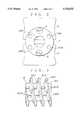
- FIG. 2is a front elevational view of the annular plate and the screws coupled to the artificial vertebra spacer;
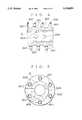
- FIG. 3is a side elevational view of the artificial vertebra spacer
- FIG. 4is a cross-sectional view of the artificial vertebra spacer
- FIG. 5is a front elevational view of the artificial vertebra spacer
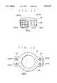
- FIG. 6is a front elevational view of the annular plate
- FIG. 7is a cross-sectional view of the annular plate
- FIG. 8is a cross-sectional view of a modified annular plate
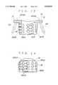
- FIG. 9is a plan view of an artificial vertebra spacer according to a second embodiment of the present invention.
- FIG. 10is a front elevational view, partly in cross section, of the artificial vertebra spacer according to the second embodiment
- FIG. 11is a side elevational view of the artificial vertebra spacer according to the second embodiment.
- FIG. 12is a plan view of an artificial vertebra spacer according to a third embodiment of the present invention.
- FIG. 13is a front elevational view, partly in cross section, of the artificial vertebra spacer according to the third embodiment
- FIG. 14is a side elevational view of the artificial vertebra spacer according to the third embodiment.
- FIG. 15is a plan view of an artificial vertebra spacer according to a fourth embodiment of the present invention.
- FIG. 16is a front elevational view, partly in cross section, of the artificial vertebra spacer according to the fourth embodiment.
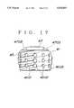
- FIG. 17is a side elevational view of the artificial vertebra spacer according to the fourth embodiment.
- the present inventionis particularly useful when embodied in an artificial vertebra spacer for spacing and interconnecting adjacent vertebrae after a faulty intervertebral disk has been removed from cervical vertebrae or lumber vertebrae of a vertebral column, as shown in FIGS. 1 and 2.
- a vertebral columnhas a spinal cord 1 and a vertical array of vertebrae 3.
- a faulty intervertebral diskhas been removed from between two adjacent vertebrae 3.
- An artificial vertebra spacer 5 according to the present inventionis embedded in and bridges the space between the adjacent vertebrae 3, and is fixed to the vertebrae 3 by an annular plate 7 and two screws 9.
- the artificial vertebra spacer 5comprises a hollow cylindrical member 501 and a helical screw thread or rib 503 of trapezoidal cross section disposed integrally on and extending helically around the hollow cylindrical member 501.
- the hollow cylindrical member 501is of such a length that when it is embedded in the adjacent vertebrae 3, its inner distal end terminates short of the rear surfaces of the vertebrae 3 which face the spinal cord 1, leaving vertebral portions 311 between the inner end of the hollow cylindrical member 501 and the rear surfaces of the vertebrae 3.
- the hollow cylindrical member 501has a plurality of radial holes 505 defined therein which communicate between inner and outer circumferential surfaces of the hollow cylindrical member 501.
- the helical screw thread 503has six screw holes 507 angularly spaced at equiangular intervals in the circumferential direction.
- the screw holes 507extend parallel to the axis of the hollow cylindrical member 501.
- the artificial vertebra spacer 5is made of a titanium alloy and coated with a calcium phosphate compound which is porous hydroxy apatite in the illustrated embodiment.
- the annular plate 7comprises a smaller-diameter tubular member 701 and a circular flange 703 extending radially outwardly from an axial end of the tubular member 701.
- the tubular member 701has an outside diameter small enough to fit in the hollow cylindrical member 501.
- the circular flange 703has an outside diameter which is substantially the same as the outside diameter of the helical screw thread 103.
- the circular flange 703has six insertion holes 705 angularly spaced at equiangular intervals in the circumferential direction.
- the insertion holes 705are identical in size to the screw holes 507 in the helical screw thread 503, and are alignable respectively with the screw holes 507.
- the annular plate 7is made of a titanium alloy and coated with a calcium phosphate compound which is porous hydroxy apatite in the illustrated embodiment.
- Each of the screws 9comprises a shank 901 and a head 903 on one end of the shank 901, as shown in FIG. 1.
- the shank 901 of each screw 9has an externally threaded surface, and can be threaded into the screw holes 507 in the helical screw thread 103.
- the shank 901 of each screw 9has a length such that it can be inserted through one of the insertion holes 705 all the way into an aligned one of the screw holes 507, with its tip end reaching the distal end of the artificial vertebra spacer 5 and the head 9 held against the outer surface of the annular plate 7.
- Each of the screws 9is made of a titanium alloy and coated with a calcium phosphate compound which is porous hydroxy apatite in the illustrated embodiment.
- annular groove 301which is of such a size as to snugly receive the hollow cylindrical member 501 is formed jointly in the two adjacent vertebrae 3.
- a helical groove 303which is of such a size as to snugly receive the helical screw thread 503 is also formed jointly in the two adjacent vertebrae 3 radially outwardly of and in communication with the annular groove 301.
- two small holeswhich are smaller in diameter than the screw holes 507 and as long as the screws 9, are formed respectively in the vertebrae 3. These two small holes extend across the helical groove 303, and are diametrically oppositely positioned in alignment with diametrically opposite two of the six screw holes 507, which are lined up with the spinal cord 1 after the artificial vertebra spacer 5 is rotated to insert the hollow cylindrical member 501 and the helical screw thread 503 fully into the annular groove 301 and the helical groove 303, respectively.
- Recesses 305are formed in front confronting portions of the vertebrae 3 for receiving the tubular member 701 of the annular plate 7.
- the hollow cylindrical member 501 and the helical screw thread 503are axially inserted into the annular groove 301 and the helical groove 303, respectively, while the artificial vertebra spacer 5 is being rotated.
- the artificial vertebra spacer 5is continuously rotated to insert the hollow cylindrical member 501 and the helical screw thread 503 fully into the annular groove 301 and the helical groove 303, respectively, i.e., until the outer end of the artificial vertebra spacer 5 projects slightly on the front surfaces of the vertebrae 3.
- vertebrae 3have respective confronting portions 307 contiguous to the respective vertebral portions 311 and positioned within the hollow cylindrical member 501.
- the rotation of the artificial vertebra spacer 5is stopped with two of the screw holes 507 being aligned with the two small holes in the respective vertebrae 3.
- the tubular member 701 of the annular plate 7is fitted in the hollow cylindrical member 501 and accommodated in the recesses 305, and the annular plate 7 is turned to bring the insertion holes 705 into alignment with the respective screw holes 507.
- the two screws 9are thereafter inserted through the respective insertion holes 705 and threaded into the two screw holes 507 and the aligned small holes in the vertebrae 3.
- the screws 9are tightened until their heads 903 are engaged by the outer surface of the annular plate 7.
- the artificial vertebra spacer 5Since the artificial vertebra spacer 5 is embedded in and secured to the superiorly adjacent and interiorly adjacent vertebrae 3 and the confronting portions 307 of the vertebrae 3 are left within the hollow cylindrical member 501, the artificial vertebra spacer 5 can bear compressive forces, tensile forces, and forces normal to these compressive and tensile forces, all of which are applied to the vertebrae 3. Therefore, even when the vertebrae 3 are subjected to compressive forces, tensile forces, or forces normal to these compressive and tensile forces, the vertebrae 3 are stably held in position by the artificial vertebra spacer 5.
- the bone tissue of the confronting portions 307 of the vertebrae 3 which remain positioned within the hollow cylindrical member 501grows to the extent that the confronting portions 307 are fused to each other. Therefore, the vertebrae 3 can stably be held together.
- the artificial vertebra spacer 5, the annular plate 7, and the screws 9are all made of a titanium alloy and coated with a calcium phosphate compound, as described above.
- the artificial vertebra spacer 5, the annular plate 7, and the screws 9are relatively light.
- the calcium phosphate compoundhas a high bone fusion capability, the surface layers of the artificial vertebra spacer 5, the annular plate 7, and the screws 9 can well be fused to the vertebrae 3, with the result that the artificial vertebra spacer 5 can reliably be anchored to the vertebrae 3.
- the mechanical strength and rigidity of the artificial vertebra spacer 5are increased by the annular plate 7 and the screws 9 for stably holding the vertebrae 3 in place.
- FIG. 8shows a modified annular plate 71.
- the modified annular plate 71comprises a partly cylindrical flange 713 extending radially outwardly from an end of a tubular member 701.
- the flange 713has six insertion holes 715 defined therein at equiangular intervals.
- the front end surfaces of the vertebrae 3are cut off, defining a partly cylindrical recess complementary in shape to the partly cylindrical flange 713.
- the partly cylindrical flange 713is snugly fitted in the partly cylindrical recess thus defined. Consequently, the modified annular plate 71 does not greatly project from the vertebrae 3.
- the artificial vertebra spacer 5may be embedded in the adjacent vertebrae 3 while a spacer or filler which has a bone fusion capability or biocompatibility is being interposed between the confronting portions 307 of the vertebrae 3.
- the artificial vertebra spacer 5 fixed to the vertebrae 3is reinforced by the annular plate 7 and the screw 9 for increased mechanical strength and rigidity.
- the annular plate 7 and the screws 9may be dispensed with.
- the artificial vertebra spacer 5may be fixed to the vertebrae 3 in various ways.
- the hollow cylindrical member 501may be externally threaded and may be fixedly held in position in the vertebrae 3 through threaded engagement.
- the hollow cylindrical member 501may have a flange on an end thereof, and the artificial vertebra spacer 5 may be fixed to the vertebrae 3 by screws extending through the flange and threaded into the vertebrae 3.
- the hollow cylindrical member 501may have an increased wall thickness or may be made of a different material for increasing the mechanical strength and rigidity of the artificial vertebra spacer 5.
- the artificial vertebra spacer 5may be of a hollow rectangular shape, rather than a hollow cylindrical shape.
- FIGS. 9 though 11show an artificial vertebra spacer according to a second embodiment of the present invention.
- the artificial vertebra spacerdenoted at 21, according to the second embodiment comprises a hollow cylindrical member 25 and a flange 27 integrally joined to an end of the hollow cylindrical member 25.
- the hollow cylindrical member 25has a helical screw thread or rib 2501 on its outer circumferential surface.
- the hollow cylindrical member 25is of such a length that when it is embedded in the adjacent vertebrae 3 (see FIGS. 1 and 2), its inner distal end terminates short of the rear surfaces of the vertebrae 3 which face the spinal cord 1, leaving vertebral portions 311 between the inner end of the hollow cylindrical member 25 and the rear surfaces of the vertebrae 3.
- the hollow cylindrical member 25has a plurality of radial holes 2502 defined therein which communicates between inner and outer circumferential surfaces of the hollow cylindrical member 25.
- the hollow cylindrical member 25has a tapered outer surface 2503 on its end opposite to the flange 27 so that the hollow cylindrical member 25 can easily penetrate and be embedded in the vertebrae 3.
- the flange 27is of a rectangular shape with screw insertion holes 2701 defined in respective four corners thereof. As shown in FIG. 11, the flange 27 has a partly cylindrical surface 2703 on its outer side remote from the hollow cylindrical member 25.
- Screws 29can be inserted through the respective screw insertion holes 2701 threadedly into the vertebrae 3 for fastening the artificial vertebra spacer 21 to the vertebrae 3.
- the artificial vertebra spacer 21 and the screws 29are made of a titanium alloy and not coated with a calcium phosphate compound.
- the artificial vertebra spacer 21 and screws 29may be coated with a calcium phosphate compound.
- Two adjacent vertebrae 3 positioned superiorly and interiorly of a removed faulty intervertebral disk, respectively,can be interconnected in spaced-apart relationship by the artificial vertebra spacer 21 as follows.
- annular groove which is of such a size as to snugly receive the hollow cylindrical member 25is formed jointly in the two adjacent vertebrae 3. Then, the artificial vertebra spacer 21 is fitted into the annular groove while it is being rotated until the artificial vertebra spacer 21 is embedded in the vertebrae 3.
- a helical groove which is of such a size as to snugly receive the helical screw thread 2501may be formed jointly in the two adjacent vertebrae 3 before the hollow cylindrical member 25 is inserted into the annular groove, so that the helical screw thread 2501 will be received in the helical groove when the artificial vertebra spacer 21 is embedded in the vertebrae 3. Alternatively, no such helical groove may be formed, and the vertebrae 3 may be tapped by the self-tapping helical screw thread 2501 when the hollow cylindrical member 25 is inserted into the annular groove.
- the artificial vertebra spacer 21Since the artificial vertebra spacer 21 is embedded in and secured to the superiorly and interiorly adjacent vertebrae 3, and the vertebrae 3 have respective confronting portions 307 left within the hollow cylindrical member 25, the artificial vertebra spacer 21 can bear compressive forces, tensile forces, and forces normal to these compressive and tensile forces, all of which are applied to the vertebrae 3. Therefore, even when the vertebrae 3 are subjected to compressive forces, tensile forces, or forces normal to these compressive and tensile forces, the vertebrae 3 are stably held in position by the artificial vertebra spacer 21.
- the bone tissue of the confronting portions of the vertebrae 3 which remain positioned within the hollow cylindrical member 25grows to the extent that the confronting portions are fused to each other. Therefore, the vertebrae 3 can stably be held together.
- the bone tissue of the vertebrae 3 as it growsenters the holes 2502 in the hollow cylindrical member 25. Therefore, the confronting portions of the vertebrae 3 which remain positioned within the hollow cylindrical member 25, and vertebral portions positioned radially outwardly of the hollow cylindrical member 25, are fused to each other through the holes 2502, thereby holding the vertebrae 3 stably in position.
- FIGS. 12 through 14An artificial vertebra spacer according to a third embodiment of the present invention will be described below with reference to FIGS. 12 through 14.
- the artificial vertebra spacerdiffers from the artificial vertebra spacer 21 according to the second embodiment with regard to the flange joined to the hollow cylindrical member.
- the artificial vertebra spacer 31comprises a hollow cylindrical member 35 and a pair of diametrically opposite flanges 37 integrally joined to an end of the hollow cylindrical member 35.
- the hollow cylindrical member 35has a helical screw thread or rib 3501 on its outer circumferential surface, a plurality of radial holes 3502 defined therein which communicate between inner and outer circumferential surfaces of the hollow cylindrical member 35, and a tapered outer surface 3503 with its diameter which tapers progressively smaller in a direction away from the end of the hollow cylindrical member 35 with the flanges 37.
- the flanges 37project radially outwardly from diametrically opposite sides, respectively, of the hollow cylindrical member 35.
- Each of the flanges 37is substantially rectangular in shape, and has two screw insertion holes 3701 defined therein near its outer distal end.
- the artificial vertebra spacer 31has a partly cylindrical surface 3703 on the end of the hollow cylindrical member 35 to which the flanges 37 are joined. The partly cylindrical surface 3703 blends into the outer surfaces of the flanges 37.
- the screw insertion holes 3701have respective axes 3701A inclined with respect to the axis of the hollow cylindrical member 35, such that screws 39 inserted through the screw insertion holes 3701 to fasten the artificial vertebra spacer 31 the vertebrae 3, have tip ends pointed obliquely away from each other.
- the artificial vertebra spacer 31 and the screws 39are made of a titanium alloy and are not coated with a calcium phosphate compound.
- the artificial vertebra spacer 31 and screws 39may be coated with a calcium phosphate compound.
- FIGS. 15 through 17show an artificial vertebra spacer according to a fourth embodiment of the present invention.
- the artificial vertebra spacerdiffers from the artificial vertebra spacer 31 according to the third embodiment, in that the artificial vertebra spacers 41 has a single flange.
- the artificial vertebra spacer 41comprises a hollow cylindrical member 45 and a flange 47, integrally joined to an end of the hollow cylindrical member 35.
- the hollow cylindrical member 45has a helical screw thread or rib 4501 on its outer circumferential surface, a plurality of radial holes 4502 defined therein which communicate between inner and outer circumferential surfaces of the hollow cylindrical member 45, and a tapered outer surface 4503 with a diameter which tapers progressively smaller in a direction away from the end of the hollow cylindrical member 45 with the flange 47.
- the flange 47projects radially outwardly from one side of the hollow cylindrical member 45.
- the flange 47is substantially rectangular in shape, and has two screw insertion holes 4701 defined therein near its outer distal end.
- the screw insertion holes 4701have respective inclined axes 4701A, so that screws 49 inserted therethrough are inclined with respect to the axis of the hollow cylindrical member 45.
- the artificial vertebra spacer 41has a partly cylindrical surface 4703 on the end of the hollow cylindrical member 45 to which the flange 47 is joined, the partly cylindrical surface 4703 blending into the outer surface of the flange 47.
- the hollow cylindrical member 35has a beveled surface 4509, on a side thereof, that is diametrically opposite to the flange 47.
- the artificial vertebra spacer 41 and the screws 49are made of a titanium alloy and are not coated with a calcium phosphate compound.
- the artificial vertebra spacer 41 and screws 49may be coated with a calcium phosphate compound.
Landscapes
- Health & Medical Sciences (AREA)
- Animal Behavior & Ethology (AREA)
- Biomedical Technology (AREA)
- Engineering & Computer Science (AREA)
- Veterinary Medicine (AREA)
- Chemical & Material Sciences (AREA)
- Public Health (AREA)
- General Health & Medical Sciences (AREA)
- Life Sciences & Earth Sciences (AREA)
- Oral & Maxillofacial Surgery (AREA)
- Epidemiology (AREA)
- Transplantation (AREA)
- Inorganic Chemistry (AREA)
- Neurology (AREA)
- Orthopedic Medicine & Surgery (AREA)
- Heart & Thoracic Surgery (AREA)
- Vascular Medicine (AREA)
- Medicinal Chemistry (AREA)
- Dermatology (AREA)
- Cardiology (AREA)
- Surgery (AREA)
- Prostheses (AREA)
Abstract
Description
This application is a continuation of application Ser. No. 08/009,916, filed Jan. 27, 1993, now abandoned.
The present disclosure relates to subject matter contained in Japanese patent application No. 4-38566 (filed on Jan. 28, 1992) which is expressly incorporated herein by reference in its entirety.
1. Field of the Invention
The present invention relates to an artificial spacer for keeping adjacent vertebrae spaced from each other after a faulty intervertebral disk has been removed from cervical vertebrae or lumbar vertebrae of a vertebral column.
2. Description of the Relevant Art
In a known surgical procedure to be carried out on a patient who is suffering a spinal failure such as the herniation of an intervertebral disk, the faulty intervertebral disk is removed anteriorly of the patient, and a vertebra filler or spacer is inserted between the vertebrae that are positioned above and below the removed intervertebral disk.
Vertebra fillers that are known for use in the above procedure include autografts taken from the patients' iliac bones, and bioceramic bones (allografts) of alumina, hydroxy apatite, or the like.
According to the above medical operation, confronting portions of the vertebrae positioned superiorly and interiorly of the removed intervertebral disk are cut off, and the vertebra spacer is inserted between the vertebrae from the anterior side of the patient, filling up the space between the vertebrae. The vertebra filler is effective to hold the vertebrae in position against compressive forces applied thereto. However, it is less effective to hold the vertebrae in position when tensile forces or forces normal to the compressive or tensile forces are applied thereto.
It is therefore an object of the present invention to provide an artificial vertebra spacer which is capable of holding adjacent vertebrae stably in position against compressive and tensile forces and also forces normal to the compressive and tensile forces.
According to the present invention, there is provided an artificial vertebra spacer comprising a hollow member adapted to be embedded in two adjacent vertebrae which are positioned superiorly and interiorly of a removed intervertebral disk, respectively, with respective confronting portions of the vertebrae being positioned within the hollow member, the hollow member being made of a material having a predetermined degree of mechanical strength and rigidity.
According to another aspect of the present invention, there is also provided an assembly comprising an artificial vertebra spacer comprising a hollow member adapted to be embedded in two adjacent vertebrae which are positioned superiorly and interiorly of a removed intervertebral disk, respectively, with respective confronting portions of the vertebrae being positioned within the hollow member, the hollow member being made of a material having a predetermined degree of mechanical strength and rigidity, and a plate connected to an end of the artificial vertebra spacer which is exposed on the vertebrae when the hollow member is embedded in the vertebrae. The hollow member may be of a cylindrical shape and have a helical screw thread on an outer circumferential surface, the helical screw thread having screw holes defined therein parallel to an axis of the hollow member, the plate being of an annular shape having an outside diameter which is substantially the same as the outside diameter of the helical screw thread, further comprising at least one screw extending through the plate and threaded into the screw holes defined in the helical screw thread, thereby fastening the plate to the artificial vertebra spacer.
According to still another aspect of the present invention, there is provided an artificial vertebra spacer for being embedded in and bridging a space between two adjacent vertebrae which are positioned superiorly and interiorly of a removed intervertebral disk, respectively the artificial vertebra spacer comprising a hollow cylindrical member, and a helical screw thread disposed integrally on and extending helically around the hollow cylindrical member, each of the hollow cylindrical member and the helical screw thread being made of a metallic material and having a surface layer made of a biocompatible material.
According to yet still another aspect of the present invention, there is provided an assembly comprising an artificial vertebra spacer for being embedded in and bridging a space between two adjacent vertebrae which are positioned superiorly and interiorly of a removed intervertebral disk, respectively, the artificial vertebra spacer comprising a hollow cylindrical member, and a helical screw thread disposed integrally on and extending helically around the hollow cylindrical member, an annular plate having a tubular member fitted in an axial end of the artificial vertebra spacer and a circular flange extending radially outwardly from the tubular member, and at least one screw for fastening the circular flange to the helical screw thread when the artificial vertebra spacer is embedded in the vertebrae.
Each of the artificial vertebra spacer, the annular plate, and the at least one screw may be made of a titanium alloy.
According to yet still another aspect of the present invention, there is provided an artificial vertebra spacer comprising a hollow cylindrical member adapted to be embedded in two adjacent vertebrae, screw means, provided on an outer circumferential surface of the hollow cylindrical member, for connecting the hollow cylindrical member with the two adjacent vertebrae, and fixing means for fixing the hollow cylindrical member to the vertebrae.
The above and further objects, details and advantages of the present invention will become apparent from the following detailed description of preferred embodiments thereof, when read in conjunction with the accompanying drawings.
FIG. 1 is a cross-sectional view of an artificial vertebra spacer according to a first embodiment of the present invention, with an annular plate and screws as they are used to interconnect adjacent vertebrae;
FIG. 2 is a front elevational view of the annular plate and the screws coupled to the artificial vertebra spacer;
FIG. 3 is a side elevational view of the artificial vertebra spacer;
FIG. 4 is a cross-sectional view of the artificial vertebra spacer;
FIG. 5 is a front elevational view of the artificial vertebra spacer;
FIG. 6 is a front elevational view of the annular plate;
FIG. 7 is a cross-sectional view of the annular plate;
FIG. 8 is a cross-sectional view of a modified annular plate;
FIG. 9 is a plan view of an artificial vertebra spacer according to a second embodiment of the present invention;
FIG. 10 is a front elevational view, partly in cross section, of the artificial vertebra spacer according to the second embodiment;
FIG. 11 is a side elevational view of the artificial vertebra spacer according to the second embodiment;
FIG. 12 is a plan view of an artificial vertebra spacer according to a third embodiment of the present invention;
FIG. 13 is a front elevational view, partly in cross section, of the artificial vertebra spacer according to the third embodiment;
FIG. 14 is a side elevational view of the artificial vertebra spacer according to the third embodiment;
FIG. 15 is a plan view of an artificial vertebra spacer according to a fourth embodiment of the present invention;
FIG. 16 is a front elevational view, partly in cross section, of the artificial vertebra spacer according to the fourth embodiment; and
FIG. 17 is a side elevational view of the artificial vertebra spacer according to the fourth embodiment.
The present invention is particularly useful when embodied in an artificial vertebra spacer for spacing and interconnecting adjacent vertebrae after a faulty intervertebral disk has been removed from cervical vertebrae or lumber vertebrae of a vertebral column, as shown in FIGS. 1 and 2.
As shown in FIGS. 1 and 2, a vertebral column has a spinal cord 1 and a vertical array ofvertebrae 3. In FIGS. 1 and 2, a faulty intervertebral disk has been removed from between twoadjacent vertebrae 3. Anartificial vertebra spacer 5 according to the present invention is embedded in and bridges the space between theadjacent vertebrae 3, and is fixed to thevertebrae 3 by anannular plate 7 and twoscrews 9.
As shown in FIGS. 3, 4, and 5, theartificial vertebra spacer 5 comprises a hollowcylindrical member 501 and a helical screw thread orrib 503 of trapezoidal cross section disposed integrally on and extending helically around the hollowcylindrical member 501. When theartificial vertebra spacer 5 is embedded in theadjacent vertebrae 3, it has an outer end exposed on front surfaces of thevertebrae 3. As shown in FIG. 1, the hollowcylindrical member 501 is of such a length that when it is embedded in theadjacent vertebrae 3, its inner distal end terminates short of the rear surfaces of thevertebrae 3 which face the spinal cord 1, leavingvertebral portions 311 between the inner end of the hollowcylindrical member 501 and the rear surfaces of thevertebrae 3. The hollowcylindrical member 501 has a plurality ofradial holes 505 defined therein which communicate between inner and outer circumferential surfaces of the hollowcylindrical member 501.
As shown in FIG. 5, thehelical screw thread 503 has sixscrew holes 507 angularly spaced at equiangular intervals in the circumferential direction. Thescrew holes 507 extend parallel to the axis of the hollowcylindrical member 501.
Theartificial vertebra spacer 5 is made of a titanium alloy and coated with a calcium phosphate compound which is porous hydroxy apatite in the illustrated embodiment.
As shown in FIGS. 6 and 7, theannular plate 7 comprises a smaller-diametertubular member 701 and acircular flange 703 extending radially outwardly from an axial end of thetubular member 701.
Thetubular member 701 has an outside diameter small enough to fit in the hollowcylindrical member 501. Thecircular flange 703 has an outside diameter which is substantially the same as the outside diameter of the helical screw thread 103. Thecircular flange 703 has sixinsertion holes 705 angularly spaced at equiangular intervals in the circumferential direction. Theinsertion holes 705 are identical in size to thescrew holes 507 in thehelical screw thread 503, and are alignable respectively with thescrew holes 507.
Theannular plate 7 is made of a titanium alloy and coated with a calcium phosphate compound which is porous hydroxy apatite in the illustrated embodiment.
Each of thescrews 9 comprises ashank 901 and ahead 903 on one end of theshank 901, as shown in FIG. 1.
Theshank 901 of eachscrew 9 has an externally threaded surface, and can be threaded into thescrew holes 507 in the helical screw thread 103. Theshank 901 of eachscrew 9 has a length such that it can be inserted through one of theinsertion holes 705 all the way into an aligned one of thescrew holes 507, with its tip end reaching the distal end of theartificial vertebra spacer 5 and thehead 9 held against the outer surface of theannular plate 7.
Each of thescrews 9 is made of a titanium alloy and coated with a calcium phosphate compound which is porous hydroxy apatite in the illustrated embodiment.
A process of interconnecting twoadjacent vertebrae 3 positioned above and below a removed faulty intervertebral disk in spaced-apart relationship will be described below with reference to FIG. 1.
First, anannular groove 301 which is of such a size as to snugly receive the hollowcylindrical member 501 is formed jointly in the twoadjacent vertebrae 3. Ahelical groove 303 which is of such a size as to snugly receive thehelical screw thread 503 is also formed jointly in the twoadjacent vertebrae 3 radially outwardly of and in communication with theannular groove 301.
Then, two small holes, which are smaller in diameter than the screw holes 507 and as long as thescrews 9, are formed respectively in thevertebrae 3. These two small holes extend across thehelical groove 303, and are diametrically oppositely positioned in alignment with diametrically opposite two of the sixscrew holes 507, which are lined up with the spinal cord 1 after theartificial vertebra spacer 5 is rotated to insert the hollowcylindrical member 501 and thehelical screw thread 503 fully into theannular groove 301 and thehelical groove 303, respectively.
Recesses 305 are formed in front confronting portions of thevertebrae 3 for receiving thetubular member 701 of theannular plate 7.
Thereafter, the hollowcylindrical member 501 and thehelical screw thread 503 are axially inserted into theannular groove 301 and thehelical groove 303, respectively, while theartificial vertebra spacer 5 is being rotated. Theartificial vertebra spacer 5 is continuously rotated to insert the hollowcylindrical member 501 and thehelical screw thread 503 fully into theannular groove 301 and thehelical groove 303, respectively, i.e., until the outer end of theartificial vertebra spacer 5 projects slightly on the front surfaces of thevertebrae 3. At this stage of the insertion,vertebrae 3 have respective confrontingportions 307 contiguous to the respectivevertebral portions 311 and positioned within the hollowcylindrical member 501. The rotation of theartificial vertebra spacer 5 is stopped with two of the screw holes 507 being aligned with the two small holes in therespective vertebrae 3.
Then, thetubular member 701 of theannular plate 7 is fitted in the hollowcylindrical member 501 and accommodated in the recesses 305, and theannular plate 7 is turned to bring the insertion holes 705 into alignment with the respective screw holes 507.
The twoscrews 9 are thereafter inserted through therespective insertion holes 705 and threaded into the twoscrew holes 507 and the aligned small holes in thevertebrae 3. Thescrews 9 are tightened until theirheads 903 are engaged by the outer surface of theannular plate 7.
Since theartificial vertebra spacer 5 is embedded in and secured to the superiorly adjacent and interiorlyadjacent vertebrae 3 and the confrontingportions 307 of thevertebrae 3 are left within the hollowcylindrical member 501, theartificial vertebra spacer 5 can bear compressive forces, tensile forces, and forces normal to these compressive and tensile forces, all of which are applied to thevertebrae 3. Therefore, even when thevertebrae 3 are subjected to compressive forces, tensile forces, or forces normal to these compressive and tensile forces, thevertebrae 3 are stably held in position by theartificial vertebra spacer 5. After theartificial vertebra spacer 5 has been embedded, the bone tissue of the confrontingportions 307 of thevertebrae 3 which remain positioned within the hollowcylindrical member 501 grows to the extent that the confrontingportions 307 are fused to each other. Therefore, thevertebrae 3 can stably be held together.
The bone tissue of thevertebrae 3 as it grows enters theholes 505 in the hollowcylindrical member 501. Therefore, the confrontingportions 307 of thevertebrae 3 which remain positioned within the hollowcylindrical member 501 andvertebral portions 313 positioned radially outwardly of the hollowcylindrical member 501 are fused to each other through theholes 505, thereby holding thevertebrae 3 stably in position. Since the coating of calcium phosphate compound on the hollowcylindrical member 501 is highly biocompatible, the bone tissue of thevertebrae 3 finds it easy to enter theholes 505, allowing easy fusion between the confrontingportions 307 of thevertebrae 3 which remain positioned within the hollowcylindrical member 501 and thevertebral portions 313 positioned radially outwardly of the hollowcylindrical member 501.
Theartificial vertebra spacer 5, theannular plate 7, and thescrews 9 are all made of a titanium alloy and coated with a calcium phosphate compound, as described above. Thus, theartificial vertebra spacer 5, theannular plate 7, and thescrews 9 are relatively light. As the calcium phosphate compound has a high bone fusion capability, the surface layers of theartificial vertebra spacer 5, theannular plate 7, and thescrews 9 can well be fused to thevertebrae 3, with the result that theartificial vertebra spacer 5 can reliably be anchored to thevertebrae 3.
The mechanical strength and rigidity of theartificial vertebra spacer 5 are increased by theannular plate 7 and thescrews 9 for stably holding thevertebrae 3 in place.
FIG. 8 shows a modifiedannular plate 71. The modifiedannular plate 71 comprises a partlycylindrical flange 713 extending radially outwardly from an end of atubular member 701. Theflange 713 has sixinsertion holes 715 defined therein at equiangular intervals. To use the modifiedannular plate 71, the front end surfaces of thevertebrae 3 are cut off, defining a partly cylindrical recess complementary in shape to the partlycylindrical flange 713. In use, the partlycylindrical flange 713 is snugly fitted in the partly cylindrical recess thus defined. Consequently, the modifiedannular plate 71 does not greatly project from thevertebrae 3.
Theartificial vertebra spacer 5 may be embedded in theadjacent vertebrae 3 while a spacer or filler which has a bone fusion capability or biocompatibility is being interposed between the confrontingportions 307 of thevertebrae 3.
In the illustrated embodiment, theartificial vertebra spacer 5 fixed to thevertebrae 3 is reinforced by theannular plate 7 and thescrew 9 for increased mechanical strength and rigidity. However, theannular plate 7 and thescrews 9 may be dispensed with.
Theartificial vertebra spacer 5 may be fixed to thevertebrae 3 in various ways. For example, the hollowcylindrical member 501 may be externally threaded and may be fixedly held in position in thevertebrae 3 through threaded engagement. Alternatively, the hollowcylindrical member 501 may have a flange on an end thereof, and theartificial vertebra spacer 5 may be fixed to thevertebrae 3 by screws extending through the flange and threaded into thevertebrae 3. In the case where theannular plate 7 and thescrews 9 are dispensed with, the hollowcylindrical member 501 may have an increased wall thickness or may be made of a different material for increasing the mechanical strength and rigidity of theartificial vertebra spacer 5.
Alternatively, theartificial vertebra spacer 5 may be of a hollow rectangular shape, rather than a hollow cylindrical shape.
FIGS. 9 though 11 show an artificial vertebra spacer according to a second embodiment of the present invention.
The artificial vertebra spacer, denoted at 21, according to the second embodiment comprises a hollowcylindrical member 25 and aflange 27 integrally joined to an end of the hollowcylindrical member 25. The hollowcylindrical member 25 has a helical screw thread orrib 2501 on its outer circumferential surface.
The hollowcylindrical member 25 is of such a length that when it is embedded in the adjacent vertebrae 3 (see FIGS. 1 and 2), its inner distal end terminates short of the rear surfaces of thevertebrae 3 which face the spinal cord 1, leavingvertebral portions 311 between the inner end of the hollowcylindrical member 25 and the rear surfaces of thevertebrae 3. The hollowcylindrical member 25 has a plurality ofradial holes 2502 defined therein which communicates between inner and outer circumferential surfaces of the hollowcylindrical member 25. The hollowcylindrical member 25 has a taperedouter surface 2503 on its end opposite to theflange 27 so that the hollowcylindrical member 25 can easily penetrate and be embedded in thevertebrae 3.
Theflange 27 is of a rectangular shape withscrew insertion holes 2701 defined in respective four corners thereof. As shown in FIG. 11, theflange 27 has a partlycylindrical surface 2703 on its outer side remote from the hollowcylindrical member 25.
Theartificial vertebra spacer 21 and thescrews 29 are made of a titanium alloy and not coated with a calcium phosphate compound. Optionally, theartificial vertebra spacer 21 and screws 29 may be coated with a calcium phosphate compound.
Twoadjacent vertebrae 3 positioned superiorly and interiorly of a removed faulty intervertebral disk, respectively, can be interconnected in spaced-apart relationship by theartificial vertebra spacer 21 as follows.
First, as with the first embodiment, an annular groove which is of such a size as to snugly receive the hollowcylindrical member 25 is formed jointly in the twoadjacent vertebrae 3. Then, theartificial vertebra spacer 21 is fitted into the annular groove while it is being rotated until theartificial vertebra spacer 21 is embedded in thevertebrae 3. A helical groove which is of such a size as to snugly receive thehelical screw thread 2501 may be formed jointly in the twoadjacent vertebrae 3 before the hollowcylindrical member 25 is inserted into the annular groove, so that thehelical screw thread 2501 will be received in the helical groove when theartificial vertebra spacer 21 is embedded in thevertebrae 3. Alternatively, no such helical groove may be formed, and thevertebrae 3 may be tapped by the self-tappinghelical screw thread 2501 when the hollowcylindrical member 25 is inserted into the annular groove.
Then, four small holes, which are smaller in diameter than thescrew insertion holes 2701, and as long as thescrews 29, are formed in thevertebrae 3. These four small holes may be formed at the same time that the annular groove is formed in thevertebrae 3. Thescrews 29 are thereafter inserted through the respectivescrew insertion holes 2701 and threaded into the small holes in thevertebrae 3. Thescrews 9 are tightened until their heads are engaged by the outer surface of theflange 27.
Since theartificial vertebra spacer 21 is embedded in and secured to the superiorly and interiorlyadjacent vertebrae 3, and thevertebrae 3 have respective confrontingportions 307 left within the hollowcylindrical member 25, theartificial vertebra spacer 21 can bear compressive forces, tensile forces, and forces normal to these compressive and tensile forces, all of which are applied to thevertebrae 3. Therefore, even when thevertebrae 3 are subjected to compressive forces, tensile forces, or forces normal to these compressive and tensile forces, thevertebrae 3 are stably held in position by theartificial vertebra spacer 21. After theartificial vertebra spacer 21 has been embedded, the bone tissue of the confronting portions of thevertebrae 3 which remain positioned within the hollowcylindrical member 25 grows to the extent that the confronting portions are fused to each other. Therefore, thevertebrae 3 can stably be held together.
The bone tissue of thevertebrae 3 as it grows enters theholes 2502 in the hollowcylindrical member 25. Therefore, the confronting portions of thevertebrae 3 which remain positioned within the hollowcylindrical member 25, and vertebral portions positioned radially outwardly of the hollowcylindrical member 25, are fused to each other through theholes 2502, thereby holding thevertebrae 3 stably in position.
An artificial vertebra spacer according to a third embodiment of the present invention will be described below with reference to FIGS. 12 through 14.
The artificial vertebra spacer, denoted at 31, differs from theartificial vertebra spacer 21 according to the second embodiment with regard to the flange joined to the hollow cylindrical member.
More specifically, theartificial vertebra spacer 31 comprises a hollowcylindrical member 35 and a pair of diametricallyopposite flanges 37 integrally joined to an end of the hollowcylindrical member 35. The hollowcylindrical member 35 has a helical screw thread orrib 3501 on its outer circumferential surface, a plurality ofradial holes 3502 defined therein which communicate between inner and outer circumferential surfaces of the hollowcylindrical member 35, and a taperedouter surface 3503 with its diameter which tapers progressively smaller in a direction away from the end of the hollowcylindrical member 35 with theflanges 37.
Theflanges 37 project radially outwardly from diametrically opposite sides, respectively, of the hollowcylindrical member 35. Each of theflanges 37 is substantially rectangular in shape, and has twoscrew insertion holes 3701 defined therein near its outer distal end. As shown in FIG. 14, theartificial vertebra spacer 31 has a partlycylindrical surface 3703 on the end of the hollowcylindrical member 35 to which theflanges 37 are joined. The partlycylindrical surface 3703 blends into the outer surfaces of theflanges 37.
As shown in FIG. 13, thescrew insertion holes 3701 haverespective axes 3701A inclined with respect to the axis of the hollowcylindrical member 35, such thatscrews 39 inserted through thescrew insertion holes 3701 to fasten theartificial vertebra spacer 31 thevertebrae 3, have tip ends pointed obliquely away from each other.
Theartificial vertebra spacer 31 and thescrews 39 are made of a titanium alloy and are not coated with a calcium phosphate compound. Optionally, theartificial vertebra spacer 31 and screws 39 may be coated with a calcium phosphate compound.
FIGS. 15 through 17 show an artificial vertebra spacer according to a fourth embodiment of the present invention.
The artificial vertebra spacer, denoted at 41, differs from theartificial vertebra spacer 31 according to the third embodiment, in that theartificial vertebra spacers 41 has a single flange.
More specifically, theartificial vertebra spacer 41, comprises a hollowcylindrical member 45 and aflange 47, integrally joined to an end of the hollowcylindrical member 35. The hollowcylindrical member 45 has a helical screw thread orrib 4501 on its outer circumferential surface, a plurality ofradial holes 4502 defined therein which communicate between inner and outer circumferential surfaces of the hollowcylindrical member 45, and a taperedouter surface 4503 with a diameter which tapers progressively smaller in a direction away from the end of the hollowcylindrical member 45 with theflange 47.
Theflange 47 projects radially outwardly from one side of the hollowcylindrical member 45. Theflange 47 is substantially rectangular in shape, and has twoscrew insertion holes 4701 defined therein near its outer distal end. Thescrew insertion holes 4701 have respective inclined axes 4701A, so thatscrews 49 inserted therethrough are inclined with respect to the axis of the hollowcylindrical member 45. As shown in FIG. 17, theartificial vertebra spacer 41 has a partlycylindrical surface 4703 on the end of the hollowcylindrical member 45 to which theflange 47 is joined, the partlycylindrical surface 4703 blending into the outer surface of theflange 47.
As shown in FIG. 16, the hollowcylindrical member 35 has abeveled surface 4509, on a side thereof, that is diametrically opposite to theflange 47.
Theartificial vertebra spacer 41 and thescrews 49 are made of a titanium alloy and are not coated with a calcium phosphate compound. Optionally, theartificial vertebra spacer 41 and screws 49 may be coated with a calcium phosphate compound.
Although certain preferred embodiments of the present invention have been shown and described in detail, it should be understood that various changes and modifications may be made therein without departing from the scope of the appended claims.
Claims (10)
1. An assembly member comprising:
an artificial vertebra spacer comprising a hollow member adapted to be embedded in two adjacent vertebrae which are positioned above and below a removed intervertebral disk, with respective confronting portions of the vertebrae being positioned within said hollow member, said hollow member being made of a material having a predetermined degree of mechanical strength and rigidity; and
a plate connected to an end of said artificial vertebra spacer which is exposed on the vertebrae when said hollow member is embedded in the vertebrae;
wherein said hollow member is of a cylindrical shape and has a helical screw thread on an outer circumferential surface, said helical screw thread having screw holes defined therein parallel to an axis of said hollow member, said plate being of an annular shape having an outside diameter which is substantially the same as the outside diameter of said helical screw thread, further comprising at least one screw extending through said plate and threaded into said screw holes defined in the helical screw thread, thereby fastening said plate to said artificial vertebra spacer.
2. An assembly according to claim 1, wherein said hollow member is made of a metallic material.
3. An assembly according to claim 1, wherein said plate is made of a metallic material.
4. An assembly according to claim 1, wherein said screw is made of a metallic material.
5. An assembly comprising:
an artificial vertebra spacer for being embedded in and bridging a space between two adjacent vertebrae which are positioned above and below a removed intervertebral disk, said artificial vertebra spacer comprising a hollow cylindrical member and a helical screw thread disposed integrally on and extending helically around said hollow cylindrical member;
an annular plate having a tubular member fitted in an axial end of said artificial vertebra spacer, and a circular flange extending radially outwardly from said tubular member; and
at least one screw for fastening said circular flange to said helical screw thread when said artificial vertebra spacer is embedded in the vertebrae, wherein said circular flange comprises an outside diameter substantially equal to an outside diameter of said helical screw thread.
6. An assembly according to claim 5, wherein each of said artificial vertebra spacer, said annular plate, and said at least one screw is made of a metallic material.
7. An assembly according to claim 6, wherein said metallic material comprises a titanium alloy.
8. An artificial vertebra spacer comprising:
a hollow cylindrical member adapted to be embedded in two adjacent vertebrae;
screw means, provided on an outer circumferential surface of said hollow cylindrical member, for connecting said hollow cylindrical member with said two adjacent vertebrae;
fixing means for fixing said hollow cylindrical member to said vertebrae;
wherein said screw means comprises a helical screw thread, and said fixing means comprises at least one first hole, provided at said helical screw thread, which extends parallel to the axis of said hollow cylindrical member and at least one screw to connect said hollow cylindrical member and the vertebrae through said at least one first hole; and
a flange portion provided with at least one second hole, wherein said screw passes through said second hole.
9. An artificial vertebra spacer according to claim 8, wherein said hollow cylindrical member is made of metal.
10. An artificial vertebra spacer according to claim 8, wherein said hollow cylindrical member has a plurality of holes which extend in a radial direction of said hollow cylindrical member.
Priority Applications (2)
| Application Number | Priority Date | Filing Date | Title |
|---|---|---|---|
| US08/306,430US5534031A (en) | 1992-01-28 | 1994-09-19 | Prosthesis for spanning a space formed upon removal of an intervertebral disk |
| US08/610,835US5776196A (en) | 1992-01-28 | 1996-03-05 | Prosthesis for spanning a space formed upon removal of an intervertebral disk |
Applications Claiming Priority (3)
| Application Number | Priority Date | Filing Date | Title |
|---|---|---|---|
| JP4-38566 | 1992-01-28 | ||
| JP3856692 | 1992-01-28 | ||
| US08/306,430US5534031A (en) | 1992-01-28 | 1994-09-19 | Prosthesis for spanning a space formed upon removal of an intervertebral disk |
Related Parent Applications (1)
| Application Number | Title | Priority Date | Filing Date |
|---|---|---|---|
| US991693AContinuation | 1992-01-28 | 1993-11-27 |
Related Child Applications (1)
| Application Number | Title | Priority Date | Filing Date |
|---|---|---|---|
| US08/610,835DivisionUS5776196A (en) | 1992-01-28 | 1996-03-05 | Prosthesis for spanning a space formed upon removal of an intervertebral disk |
Publications (1)
| Publication Number | Publication Date |
|---|---|
| US5534031Atrue US5534031A (en) | 1996-07-09 |
Family
ID=26377830
Family Applications (2)
| Application Number | Title | Priority Date | Filing Date |
|---|---|---|---|
| US08/306,430Expired - LifetimeUS5534031A (en) | 1992-01-28 | 1994-09-19 | Prosthesis for spanning a space formed upon removal of an intervertebral disk |
| US08/610,835Expired - Fee RelatedUS5776196A (en) | 1992-01-28 | 1996-03-05 | Prosthesis for spanning a space formed upon removal of an intervertebral disk |
Family Applications After (1)
| Application Number | Title | Priority Date | Filing Date |
|---|---|---|---|
| US08/610,835Expired - Fee RelatedUS5776196A (en) | 1992-01-28 | 1996-03-05 | Prosthesis for spanning a space formed upon removal of an intervertebral disk |
Country Status (1)
| Country | Link |
|---|---|
| US (2) | US5534031A (en) |
Cited By (159)
| Publication number | Priority date | Publication date | Assignee | Title |
|---|---|---|---|---|
| US5658335A (en)* | 1995-03-09 | 1997-08-19 | Cohort Medical Products Group, Inc. | Spinal fixator |
| US5709683A (en)* | 1995-12-19 | 1998-01-20 | Spine-Tech, Inc. | Interbody bone implant having conjoining stabilization features for bony fusion |
| US5782832A (en)* | 1996-10-01 | 1998-07-21 | Surgical Dynamics, Inc. | Spinal fusion implant and method of insertion thereof |
| WO1998048718A1 (en)* | 1997-04-25 | 1998-11-05 | Tegementa, L.L.C. | Threaded fusion cage anchoring device and method |
| US5968098A (en)* | 1996-10-22 | 1999-10-19 | Surgical Dynamics, Inc. | Apparatus for fusing adjacent bone structures |
| US5980572A (en)* | 1997-04-15 | 1999-11-09 | Asahi Kogaku Kogyo Kabushiki Kaisha | Artificial spines |
| US6004326A (en)* | 1997-09-10 | 1999-12-21 | United States Surgical | Method and instrumentation for implant insertion |
| US6063088A (en)* | 1997-03-24 | 2000-05-16 | United States Surgical Corporation | Method and instrumentation for implant insertion |
| US6083225A (en)* | 1996-03-14 | 2000-07-04 | Surgical Dynamics, Inc. | Method and instrumentation for implant insertion |
| US6117174A (en)* | 1998-09-16 | 2000-09-12 | Nolan; Wesley A. | Spinal implant device |
| WO2000066044A1 (en)* | 1999-05-05 | 2000-11-09 | Michelson Gary K | Nested interbody spinal fusion implants |
| US6190414B1 (en) | 1996-10-31 | 2001-02-20 | Surgical Dynamics Inc. | Apparatus for fusion of adjacent bone structures |
| US6228085B1 (en)* | 1998-07-14 | 2001-05-08 | Theken Surgical Llc | Bone fixation system |
| US6245072B1 (en) | 1995-03-27 | 2001-06-12 | Sdgi Holdings, Inc. | Methods and instruments for interbody fusion |
| US20010010020A1 (en)* | 1999-03-05 | 2001-07-26 | Michelson Gary K. | Interbody spinal fusion implant having an anatomically conformed trailing end |
| US6306170B2 (en) | 1997-04-25 | 2001-10-23 | Tegementa, L.L.C. | Threaded fusion cage anchoring device and method |
| US20020004683A1 (en)* | 2000-07-10 | 2002-01-10 | Michelson Gary K. | Flanged interbody spinal fusion implants |
| US6364880B1 (en)* | 1994-03-28 | 2002-04-02 | Gary Karlin Michelson | Spinal implant with bone screws |
| WO2002028323A1 (en)* | 2000-10-05 | 2002-04-11 | The Cleveland Clinic Foundation | Method and apparatus for stabilizing adjacent bones |
| US6371986B1 (en) | 1998-10-27 | 2002-04-16 | George W. Bagby | Spinal fusion device, bone joining implant, and vertebral fusion implant |
| US20020065559A1 (en)* | 2000-10-24 | 2002-05-30 | Surgical Dynamics, Inc. | Barrel-shaped apparatus for fusing adjacent bone structure |
| US6447545B1 (en) | 2000-07-01 | 2002-09-10 | George W. Bagby | Self-aligning bone implant |
| US6488683B2 (en) | 2000-11-08 | 2002-12-03 | Cleveland Clinic Foundation | Method and apparatus for correcting spinal deformity |
| US20030004572A1 (en)* | 2001-03-02 | 2003-01-02 | Goble E. Marlowe | Method and apparatus for spine joint replacement |
| US6527774B2 (en) | 2000-11-08 | 2003-03-04 | The Cleveland Clinic Foundation | Apparatus for attaching fractured sections of bone |
| US20030045935A1 (en)* | 2001-02-28 | 2003-03-06 | Angelucci Christopher M. | Laminoplasty implants and methods of use |
| US6544265B2 (en) | 2000-11-08 | 2003-04-08 | The Cleveland Clinic Foundation | Apparatus for implantation into bone related applications |
| US6551320B2 (en) | 2000-11-08 | 2003-04-22 | The Cleveland Clinic Foundation | Method and apparatus for correcting spinal deformity |
| US6551319B2 (en) | 2000-11-08 | 2003-04-22 | The Cleveland Clinic Foundation | Apparatus for implantation into bone |
| US6572653B1 (en) | 2001-12-07 | 2003-06-03 | Rush E. Simonson | Vertebral implant adapted for posterior insertion |
| US20030114854A1 (en)* | 1994-09-15 | 2003-06-19 | Howmedica Osteonics Corp. | Conically shaped anterior fusion cage and method of implantation |
| US20030181913A1 (en)* | 2000-10-05 | 2003-09-25 | The Cleveland Clinic Foundation | Apparatus for implantation into bone |
| US6626905B1 (en) | 2000-08-02 | 2003-09-30 | Sulzer Spine-Tech Inc. | Posterior oblique lumbar arthrodesis |
| US6635087B2 (en) | 2001-08-29 | 2003-10-21 | Christopher M. Angelucci | Laminoplasty implants and methods of use |
| US6645206B1 (en) | 1995-03-27 | 2003-11-11 | Sdgi Holdings, Inc. | Interbody fusion device and method for restoration of normal spinal anatomy |
| US20040010254A1 (en)* | 1999-09-03 | 2004-01-15 | Cook Daniel J. | Lumbar spine fixation device |
| US6726722B2 (en) | 2000-10-24 | 2004-04-27 | Howmedica Osteonics Corp. | Threaded apparatus for fusing adjacent bone structure |
| US6740091B2 (en) | 1997-03-06 | 2004-05-25 | Sulzer Spine-Tech Inc. | Lordotic spinal implant |
| US20040193161A1 (en)* | 2001-10-03 | 2004-09-30 | Vaughan Paul A. | Vertebral stabilization assembly and method |
| US20040225360A1 (en)* | 2000-12-14 | 2004-11-11 | Malone David G. | Devices and methods for facilitating controlled bone growth or repair |
| US20040249466A1 (en)* | 1998-08-28 | 2004-12-09 | Mingyan Liu | Expandable interbody fusion cage |
| US20050080486A1 (en)* | 2000-11-29 | 2005-04-14 | Fallin T. Wade | Facet joint replacement |
| US6899734B2 (en) | 2001-03-23 | 2005-05-31 | Howmedica Osteonics Corp. | Modular implant for fusing adjacent bone structure |
| US20050159813A1 (en)* | 2004-01-15 | 2005-07-21 | Molz Fred J.Iv | Spinal implant construct and method for implantation |
| US6966929B2 (en) | 2002-10-29 | 2005-11-22 | St. Francis Medical Technologies, Inc. | Artificial vertebral disk replacement implant with a spacer |
| US6972019B2 (en) | 2001-01-23 | 2005-12-06 | Michelson Gary K | Interbody spinal implant with trailing end adapted to receive bone screws |
| US20060085006A1 (en)* | 2002-12-03 | 2006-04-20 | Ek Steven W | System and method for retrograde procedure |
| US7041136B2 (en) | 2000-11-29 | 2006-05-09 | Facet Solutions, Inc. | Facet joint replacement |
| US7083649B2 (en) | 2002-10-29 | 2006-08-01 | St. Francis Medical Technologies, Inc. | Artificial vertebral disk replacement implant with translating pivot point |
| US7273496B2 (en) | 2002-10-29 | 2007-09-25 | St. Francis Medical Technologies, Inc. | Artificial vertebral disk replacement implant with crossbar spacer and method |
| US7320707B2 (en) | 2003-11-05 | 2008-01-22 | St. Francis Medical Technologies, Inc. | Method of laterally inserting an artificial vertebral disk replacement implant with crossbar spacer |
| US20080071375A1 (en)* | 2005-10-10 | 2008-03-20 | Carver Donna J | Artificial spinal disc replacement system and method |
| US20080249625A1 (en)* | 2007-04-03 | 2008-10-09 | Warsaw Orthopedic, Inc. | Composite Interbody Spacer |
| US7481839B2 (en) | 2003-12-02 | 2009-01-27 | Kyphon Sarl | Bioresorbable interspinous process implant for use with intervertebral disk remediation or replacement implants and procedures |
| US7481840B2 (en) | 2004-09-29 | 2009-01-27 | Kyphon Sarl | Multi-piece artificial spinal disk replacement device with selectably positioning articulating element |
| US7497859B2 (en) | 2002-10-29 | 2009-03-03 | Kyphon Sarl | Tools for implanting an artificial vertebral disk |
| US20090062630A1 (en)* | 2007-08-23 | 2009-03-05 | Siemens Aktiengesellschaft | Sensor permitting detection of a substance in the body of a living being |
| US7503935B2 (en) | 2003-12-02 | 2009-03-17 | Kyphon Sarl | Method of laterally inserting an artificial vertebral disk replacement with translating pivot point |
| US7507242B2 (en) | 2004-06-02 | 2009-03-24 | Facet Solutions | Surgical measurement and resection framework |
| US7510558B2 (en) | 2000-05-01 | 2009-03-31 | Arthrosurface, Inc. | System and method for joint resurface repair |
| US7547317B2 (en) | 2000-02-16 | 2009-06-16 | Trans1 Inc. | Methods of performing procedures in the spine |
| US7566345B1 (en) | 2001-03-01 | 2009-07-28 | Facet Solutions, Inc | Prosthesis for the replacement of a posterior element of a vertebra |
| US7569056B2 (en) | 2000-02-16 | 2009-08-04 | Trans1 Inc. | Methods and apparatus for forming shaped axial bores through spinal vertebrae |
| US7575600B2 (en) | 2004-09-29 | 2009-08-18 | Kyphon Sarl | Artificial vertebral disk replacement implant with translating articulation contact surface and method |
| US7588590B2 (en) | 2003-12-10 | 2009-09-15 | Facet Solutions, Inc | Spinal facet implant with spherical implant apposition surface and bone bed and methods of use |
| US7604641B2 (en) | 2000-05-01 | 2009-10-20 | Arthrosurface Incorporated | System and method for joint resurface repair |
| US7608077B2 (en) | 2000-02-16 | 2009-10-27 | Trans1 Inc. | Method and apparatus for spinal distraction and fusion |
| US7618462B2 (en) | 2000-05-01 | 2009-11-17 | Arthrosurface Incorporated | System and method for joint resurface repair |
| US7641657B2 (en) | 2003-06-10 | 2010-01-05 | Trans1, Inc. | Method and apparatus for providing posterior or anterior trans-sacral access to spinal vertebrae |
| US7670377B2 (en) | 2003-11-21 | 2010-03-02 | Kyphon Sarl | Laterally insertable artifical vertebral disk replacement implant with curved spacer |
| US7678151B2 (en) | 2000-05-01 | 2010-03-16 | Ek Steven W | System and method for joint resurface repair |
| US7682392B2 (en) | 2002-10-30 | 2010-03-23 | Depuy Spine, Inc. | Regenerative implants for stabilizing the spine and devices for attachment of said implants |
| US7713305B2 (en) | 2000-05-01 | 2010-05-11 | Arthrosurface, Inc. | Articular surface implant |
| US7722647B1 (en) | 2005-03-14 | 2010-05-25 | Facet Solutions, Inc. | Apparatus and method for posterior vertebral stabilization |
| US7727263B2 (en) | 2000-02-16 | 2010-06-01 | Trans1, Inc. | Articulating spinal implant |
| US20100145460A1 (en)* | 2008-11-07 | 2010-06-10 | Mcdonough William P | Zero-profile interbody spacer and coupled plate assembly |
| US7736380B2 (en) | 2004-12-21 | 2010-06-15 | Rhausler, Inc. | Cervical plate system |
| WO2010080337A1 (en) | 2008-12-18 | 2010-07-15 | Disc Dynamics, Inc. | Inflatable mold for maintaining posterior spinal elements in a desired alignment |
| US7794463B2 (en) | 2000-02-16 | 2010-09-14 | Trans1 Inc. | Methods and apparatus for performing therapeutic procedures in the spine |
| US20100274358A1 (en)* | 2009-02-25 | 2010-10-28 | Spinewelding Ag | Spine stabilization device, and method and kit for its implantation |
| US7828853B2 (en) | 2004-11-22 | 2010-11-09 | Arthrosurface, Inc. | Articular surface implant and delivery system |
| US7837732B2 (en) | 2003-11-20 | 2010-11-23 | Warsaw Orthopedic, Inc. | Intervertebral body fusion cage with keels and implantation methods |
| US20100298942A1 (en)* | 2005-04-21 | 2010-11-25 | Noah Hansell | Expandable Vertebral Prosthesis |
| US7896883B2 (en) | 2000-05-01 | 2011-03-01 | Arthrosurface, Inc. | Bone resurfacing system and method |
| US7896885B2 (en) | 2002-12-03 | 2011-03-01 | Arthrosurface Inc. | Retrograde delivery of resurfacing devices |
| US7914545B2 (en) | 2002-12-03 | 2011-03-29 | Arthrosurface, Inc | System and method for retrograde procedure |
| US7935149B2 (en) | 2001-04-02 | 2011-05-03 | Warsaw Orthopedic, Inc. | Spinal fusion implant with bone screws |
| US7951163B2 (en) | 2003-11-20 | 2011-05-31 | Arthrosurface, Inc. | Retrograde excision system and apparatus |
| US7993373B2 (en) | 2005-02-22 | 2011-08-09 | Hoy Robert W | Polyaxial orthopedic fastening apparatus |
| US8137403B2 (en) | 2001-04-02 | 2012-03-20 | Warsaw Orthopedic, Inc. | Hemi-interbody spinal fusion implants manufactured from a major long bone ring |
| US8177841B2 (en) | 2000-05-01 | 2012-05-15 | Arthrosurface Inc. | System and method for joint resurface repair |
| US8206418B2 (en) | 2007-01-10 | 2012-06-26 | Gmedelaware 2 Llc | System and method for facet joint replacement with detachable coupler |
| US8292957B2 (en) | 2000-04-19 | 2012-10-23 | Warsaw Orthopedic, Inc. | Bone hemi-lumbar arcuate interbody spinal fusion implant having an asymmetrical leading end |
| US8308777B2 (en) | 2003-10-23 | 2012-11-13 | Trans1 Inc. | Method and apparatus for removable spinal implant extending between at least two adjacent vertebral bodies |
| US8323340B2 (en) | 2000-04-19 | 2012-12-04 | Warsaw Orthopedic, Inc. | Artificial hemi-lumbar interbody spinal implant having an asymmetrical leading end |
| US8353964B2 (en) | 2010-11-04 | 2013-01-15 | Carpenter Clyde T | Anatomic total disc replacement |
| US8361159B2 (en) | 2002-12-03 | 2013-01-29 | Arthrosurface, Inc. | System for articular surface replacement |
| US8388624B2 (en) | 2003-02-24 | 2013-03-05 | Arthrosurface Incorporated | Trochlear resurfacing system and method |
| US8523872B2 (en) | 2002-12-03 | 2013-09-03 | Arthrosurface Incorporated | Tibial resurfacing system |
| US8562649B2 (en) | 2004-02-17 | 2013-10-22 | Gmedelaware 2 Llc | System and method for multiple level facet joint arthroplasty and fusion |
| US8709085B2 (en) | 2003-02-06 | 2014-04-29 | DePuy Synthes Products, LLC | Intervertebral implant |
| US8721723B2 (en) | 2009-01-12 | 2014-05-13 | Globus Medical, Inc. | Expandable vertebral prosthesis |
| US8740983B1 (en) | 2009-11-11 | 2014-06-03 | Nuvasive, Inc. | Spinal fusion implants and related methods |
| US8764801B2 (en) | 2005-03-28 | 2014-07-01 | Gmedelaware 2 Llc | Facet joint implant crosslinking apparatus and method |
| US20140207240A1 (en)* | 2013-01-24 | 2014-07-24 | Michael R. Stoffman | Percutaneous sacroiliac joint implant and method for surgically inserting and securing the implant into the sacroiliac joint |
| US8840668B1 (en) | 2009-11-11 | 2014-09-23 | Nuvasive, Inc. | Spinal implants, instruments and related methods |
| US8900273B2 (en) | 2005-02-22 | 2014-12-02 | Gmedelaware 2 Llc | Taper-locking fixation system |
| US8932358B1 (en)* | 2013-10-07 | 2015-01-13 | Daniel Nehls | Anterior intervertebral spacer and integrated plate assembly and methods of use |
| US9005295B2 (en) | 2007-11-16 | 2015-04-14 | DePuy Synthes Products, LLC | Low profile intervertebral implant |
| US9039775B2 (en) | 2003-03-31 | 2015-05-26 | DePuy Synthes Products, Inc. | Spinal fixation plates |
| US9066716B2 (en) | 2011-03-30 | 2015-06-30 | Arthrosurface Incorporated | Suture coil and suture sheath for tissue repair |
| USD742517S1 (en) | 2015-03-25 | 2015-11-03 | Orthocision Inc. | Surgical implant |
| USD745159S1 (en) | 2013-10-10 | 2015-12-08 | Nuvasive, Inc. | Intervertebral implant |
| US9220604B2 (en) | 2010-12-21 | 2015-12-29 | DePuy Synthes Products, Inc. | Intervertebral implants, systems, and methods of use |
| US9241809B2 (en) | 2010-12-21 | 2016-01-26 | DePuy Synthes Products, Inc. | Intervertebral implants, systems, and methods of use |
| US9248028B2 (en) | 2011-09-16 | 2016-02-02 | DePuy Synthes Products, Inc. | Removable, bone-securing cover plate for intervertebral fusion cage |
| US9283076B2 (en) | 2009-04-17 | 2016-03-15 | Arthrosurface Incorporated | Glenoid resurfacing system and method |
| US9358029B2 (en) | 2006-12-11 | 2016-06-07 | Arthrosurface Incorporated | Retrograde resection apparatus and method |
| US9381048B2 (en) | 2011-08-31 | 2016-07-05 | DePuy Synthes Products, Inc. | Devices and methods for cervical lateral fixation |
| US20160245318A1 (en)* | 2015-02-19 | 2016-08-25 | Mitsubishi Aircraft Corporation | Penetrated floating nut |
| US9468448B2 (en) | 2012-07-03 | 2016-10-18 | Arthrosurface Incorporated | System and method for joint resurfacing and repair |
| US9492200B2 (en) | 2013-04-16 | 2016-11-15 | Arthrosurface Incorporated | Suture system and method |
| US9521999B2 (en) | 2005-09-13 | 2016-12-20 | Arthrex, Inc. | Fully-threaded bioabsorbable suture anchor |
| US9526620B2 (en) | 2009-03-30 | 2016-12-27 | DePuy Synthes Products, Inc. | Zero profile spinal fusion cage |
| US9526493B2 (en) | 1999-02-02 | 2016-12-27 | Arthrex, Inc. | Suture anchor with insert-molded rigid member |
| US9572681B2 (en) | 2002-02-19 | 2017-02-21 | DePuy Synthes Products, Inc. | Intervertebral implant |
| US20170071746A1 (en)* | 2006-03-20 | 2017-03-16 | Joshua B. Weiss | Implant anchoring device |
| US9622739B2 (en) | 2004-04-06 | 2017-04-18 | Arthrex, Inc. | Suture anchor |
| US9662126B2 (en) | 2009-04-17 | 2017-05-30 | Arthrosurface Incorporated | Glenoid resurfacing system and method |
| US9662225B2 (en) | 2012-03-06 | 2017-05-30 | DePuy Synthes Products, Inc. | Nubbed plate |
| US9687354B2 (en) | 2008-03-26 | 2017-06-27 | DePuy Synthes Products, Inc. | Posterior intervertebral disc inserter and expansion techniques |
| US20170224393A1 (en)* | 2014-08-01 | 2017-08-10 | Ldr Medical | Bone implants |
| US9814598B2 (en) | 2013-03-14 | 2017-11-14 | Quandary Medical, Llc | Spinal implants and implantation system |
| US9861492B2 (en) | 2014-03-07 | 2018-01-09 | Arthrosurface Incorporated | Anchor for an implant assembly |
| US9867718B2 (en) | 2014-10-22 | 2018-01-16 | DePuy Synthes Products, Inc. | Intervertebral implants, systems, and methods of use |
| US9943417B2 (en) | 2012-06-29 | 2018-04-17 | DePuy Synthes Products, Inc. | Lateral insertion spinal implant |
| US9987051B2 (en) | 2015-01-27 | 2018-06-05 | K2M, Inc. | Interbody spacer |
| US10028841B2 (en) | 2015-01-27 | 2018-07-24 | K2M, Inc. | Interbody spacer |
| US10182921B2 (en) | 2012-11-09 | 2019-01-22 | DePuy Synthes Products, Inc. | Interbody device with opening to allow packing graft and other biologics |
| US10206787B2 (en) | 2006-12-22 | 2019-02-19 | Medos International Sarl | Composite vertebral spacers and instrument |
| US10335289B2 (en) | 2010-09-23 | 2019-07-02 | DePuy Synthes Products, Inc. | Stand alone intervertebral fusion device |
| US10369015B2 (en) | 2010-09-23 | 2019-08-06 | DePuy Synthes Products, Inc. | Implant inserter having a laterally-extending dovetail engagement feature |
| USD858769S1 (en) | 2014-11-20 | 2019-09-03 | Nuvasive, Inc. | Intervertebral implant |
| US10426539B2 (en) | 2013-03-15 | 2019-10-01 | Orthocision Inc. | Method and implant system for sacroiliac joint fixation and fusion |
| US10500062B2 (en) | 2009-12-10 | 2019-12-10 | DePuy Synthes Products, Inc. | Bellows-like expandable interbody fusion cage |
| US10512548B2 (en) | 2006-02-27 | 2019-12-24 | DePuy Synthes Products, Inc. | Intervertebral implant with fixation geometry |
| US10624748B2 (en) | 2014-03-07 | 2020-04-21 | Arthrosurface Incorporated | System and method for repairing articular surfaces |
| US10624752B2 (en) | 2006-07-17 | 2020-04-21 | Arthrosurface Incorporated | Tibial resurfacing system and method |
| US10940016B2 (en) | 2017-07-05 | 2021-03-09 | Medos International Sarl | Expandable intervertebral fusion cage |
| US10945743B2 (en) | 2009-04-17 | 2021-03-16 | Arthrosurface Incorporated | Glenoid repair system and methods of use thereof |
| US10959855B2 (en) | 2017-05-25 | 2021-03-30 | Stryker European Holdings I, Llc | Fusion cage with integrated fixation and insertion features |
| US11006981B2 (en) | 2017-07-07 | 2021-05-18 | K2M, Inc. | Surgical implant and methods of additive manufacturing |
| US11160663B2 (en) | 2017-08-04 | 2021-11-02 | Arthrosurface Incorporated | Multicomponent articular surface implant |
| US11478358B2 (en) | 2019-03-12 | 2022-10-25 | Arthrosurface Incorporated | Humeral and glenoid articular surface implant systems and methods |
| US11529241B2 (en) | 2010-09-23 | 2022-12-20 | DePuy Synthes Products, Inc. | Fusion cage with in-line single piece fixation |
| US11607319B2 (en) | 2014-03-07 | 2023-03-21 | Arthrosurface Incorporated | System and method for repairing articular surfaces |
| US11712276B2 (en) | 2011-12-22 | 2023-08-01 | Arthrosurface Incorporated | System and method for bone fixation |
| US12279965B2 (en) | 2017-09-08 | 2025-04-22 | Xtant Medical Holdings, Inc. | Intervertebral implants, instruments, and methods |
| US12409045B2 (en) | 2019-09-16 | 2025-09-09 | Vb Spine Us Opco Llc | 3D printed cervical standalone implant |
Families Citing this family (133)
| Publication number | Priority date | Publication date | Assignee | Title |
|---|---|---|---|---|
| CA2155422C (en) | 1993-02-10 | 2005-07-12 | Stephen D. Kuslich | Spinal stabilization surgical method |
| US6206922B1 (en) | 1995-03-27 | 2001-03-27 | Sdgi Holdings, Inc. | Methods and instruments for interbody fusion |
| US6554862B2 (en)* | 1996-11-27 | 2003-04-29 | Ethicon, Inc. | Graft ligament anchor and method for attaching a graft ligament to a bone |
| US6533816B2 (en)* | 1999-02-09 | 2003-03-18 | Joseph H. Sklar | Graft ligament anchor and method for attaching a graft ligament to a bone |
| US7083647B1 (en)* | 1996-11-27 | 2006-08-01 | Sklar Joseph H | Fixation screw, graft ligament anchor assembly, and method for securing a graft ligament in a bone tunnel |
| US5899938A (en) | 1996-11-27 | 1999-05-04 | Joseph H. Sklar | Graft ligament anchor and method for attaching a graft ligament to a bone |
| US6068630A (en)* | 1997-01-02 | 2000-05-30 | St. Francis Medical Technologies, Inc. | Spine distraction implant |
| US6168631B1 (en)* | 1997-08-29 | 2001-01-02 | Kinetikos Medical, Inc. | Subtalar implant system and method for insertion and removal |
| US6113637A (en) | 1998-10-22 | 2000-09-05 | Sofamor Danek Holdings, Inc. | Artificial intervertebral joint permitting translational and rotational motion |
| US6156037A (en)* | 1998-10-28 | 2000-12-05 | Sdgi Holdings, Inc. | Anterior lateral spine cage-plate fixation device and technique |
| AU4988700A (en)* | 1999-05-05 | 2000-11-17 | Gary K. Michelson | Spinal fusion implants with opposed locking screws |
| US7273497B2 (en) | 1999-05-28 | 2007-09-25 | Anova Corp. | Methods for treating a defect in the annulus fibrosis |
| US20060247665A1 (en) | 1999-05-28 | 2006-11-02 | Ferree Bret A | Methods and apparatus for treating disc herniation and preventing the extrusion of interbody bone graft |
| US20070038231A1 (en) | 1999-05-28 | 2007-02-15 | Ferree Bret A | Methods and apparatus for treating disc herniation and preventing the extrusion of interbody bone graft |
| US6969404B2 (en)* | 1999-10-08 | 2005-11-29 | Ferree Bret A | Annulus fibrosis augmentation methods and apparatus |
| US6491724B1 (en)* | 1999-08-13 | 2002-12-10 | Bret Ferree | Spinal fusion cage with lordosis correction |
| RU2145199C1 (en)* | 1999-06-17 | 2000-02-10 | Закрытое акционерное общество "КОНМЕТ Инкорпорейтед" | Implant for operations on vertebral column |
| US20040186573A1 (en)* | 1999-10-08 | 2004-09-23 | Ferree Bret A. | Annulus fibrosis augmentation methods and apparatus |
| US20030004574A1 (en)* | 1999-10-08 | 2003-01-02 | Ferree Bret A. | Disc and annulus augmentation using biologic tissue |
| US6592624B1 (en) | 1999-11-24 | 2003-07-15 | Depuy Acromed, Inc. | Prosthetic implant element |
| USD437055S1 (en) | 1999-12-09 | 2001-01-30 | Gary K. Michelson | Trailing end of a spinal implant |
| USD442691S1 (en) | 2000-09-28 | 2001-05-22 | Gary K. Michelson | Trailing end of a spinal implant |
| USD439340S1 (en) | 2000-01-03 | 2001-03-20 | Gary K. Michelson | End cap for a spinal implant |
| DK1294298T3 (en)* | 2000-06-26 | 2005-01-17 | Synthes Ag | Bone plate for osteosynthesis |
| US6824565B2 (en) | 2000-09-08 | 2004-11-30 | Nabil L. Muhanna | System and methods for inserting a vertebral spacer |
| US8628575B2 (en) | 2000-08-29 | 2014-01-14 | Nabil L. Muhanna | Vertebral body replacement and method of use |
| US6520993B2 (en) | 2000-12-29 | 2003-02-18 | Depuy Acromed, Inc. | Spinal implant |
| US6562073B2 (en)* | 2001-02-06 | 2003-05-13 | Sdgi Holding, Inc. | Spinal bone implant |
| US6576017B2 (en)* | 2001-02-06 | 2003-06-10 | Sdgi Holdings, Inc. | Spinal implant with attached ligament and methods |
| US6558424B2 (en) | 2001-06-28 | 2003-05-06 | Depuy Acromed | Modular anatomic fusion device |
| US6887271B2 (en)* | 2001-09-28 | 2005-05-03 | Ethicon, Inc. | Expanding ligament graft fixation system and method |
| US7527649B1 (en) | 2002-02-15 | 2009-05-05 | Nuvasive, Inc. | Intervertebral implant and related methods |
| US6726720B2 (en) | 2002-03-27 | 2004-04-27 | Depuy Spine, Inc. | Modular disc prosthesis |
| USD493533S1 (en) | 2003-02-14 | 2004-07-27 | Nuvasive, Inc. | Intervertebral implant |
| WO2004084742A1 (en) | 2003-03-24 | 2004-10-07 | Theken Surgical Llc | Spinal implant adjustment device |
| US8105367B2 (en) | 2003-09-29 | 2012-01-31 | Smith & Nephew, Inc. | Bone plate and bone plate assemblies including polyaxial fasteners |
| US8372152B2 (en) | 2003-09-30 | 2013-02-12 | X-Spine Systems, Inc. | Spinal fusion system utilizing an implant plate having at least one integral lock and ratchet lock |
| US9078706B2 (en) | 2003-09-30 | 2015-07-14 | X-Spine Systems, Inc. | Intervertebral fusion device utilizing multiple mobile uniaxial and bidirectional screw interface plates |
| US8821553B2 (en)* | 2003-09-30 | 2014-09-02 | X-Spine Systems, Inc. | Spinal fusion system utilizing an implant plate having at least one integral lock |
| US7641701B2 (en)* | 2003-09-30 | 2010-01-05 | X-Spine Systems, Inc. | Spinal fusion system and method for fusing spinal bones |
| US8062367B2 (en) | 2003-09-30 | 2011-11-22 | X-Spine Systems, Inc. | Screw locking mechanism and method |
| US7182782B2 (en)* | 2003-09-30 | 2007-02-27 | X-Spine Systems, Inc. | Spinal fusion system and method for fusing spinal bones |
| US8092547B2 (en)* | 2004-02-10 | 2012-01-10 | Tornier, Inc. | Subtalar implant assembly |
| US7608092B1 (en) | 2004-02-20 | 2009-10-27 | Biomet Sports Medicince, LLC | Method and apparatus for performing meniscus repair |
| US7544208B1 (en) | 2004-05-03 | 2009-06-09 | Theken Spine, Llc | Adjustable corpectomy apparatus |
| US7909851B2 (en) | 2006-02-03 | 2011-03-22 | Biomet Sports Medicine, Llc | Soft tissue repair device and associated methods |
| US8137382B2 (en) | 2004-11-05 | 2012-03-20 | Biomet Sports Medicine, Llc | Method and apparatus for coupling anatomical features |
| US7658751B2 (en) | 2006-09-29 | 2010-02-09 | Biomet Sports Medicine, Llc | Method for implanting soft tissue |
| US7905904B2 (en) | 2006-02-03 | 2011-03-15 | Biomet Sports Medicine, Llc | Soft tissue repair device and associated methods |
| US8361113B2 (en) | 2006-02-03 | 2013-01-29 | Biomet Sports Medicine, Llc | Method and apparatus for coupling soft tissue to a bone |
| US8303604B2 (en) | 2004-11-05 | 2012-11-06 | Biomet Sports Medicine, Llc | Soft tissue repair device and method |
| US7749250B2 (en) | 2006-02-03 | 2010-07-06 | Biomet Sports Medicine, Llc | Soft tissue repair assembly and associated method |
| US20060189993A1 (en) | 2004-11-09 | 2006-08-24 | Arthrotek, Inc. | Soft tissue conduit device |
| US8118836B2 (en) | 2004-11-05 | 2012-02-21 | Biomet Sports Medicine, Llc | Method and apparatus for coupling soft tissue to a bone |
| US8128658B2 (en) | 2004-11-05 | 2012-03-06 | Biomet Sports Medicine, Llc | Method and apparatus for coupling soft tissue to bone |
| US7905903B2 (en) | 2006-02-03 | 2011-03-15 | Biomet Sports Medicine, Llc | Method for tissue fixation |
| US8298262B2 (en) | 2006-02-03 | 2012-10-30 | Biomet Sports Medicine, Llc | Method for tissue fixation |
| US8840645B2 (en) | 2004-11-05 | 2014-09-23 | Biomet Sports Medicine, Llc | Method and apparatus for coupling soft tissue to a bone |
| US7857830B2 (en) | 2006-02-03 | 2010-12-28 | Biomet Sports Medicine, Llc | Soft tissue repair and conduit device |
| US8088130B2 (en) | 2006-02-03 | 2012-01-03 | Biomet Sports Medicine, Llc | Method and apparatus for coupling soft tissue to a bone |
| US9017381B2 (en) | 2007-04-10 | 2015-04-28 | Biomet Sports Medicine, Llc | Adjustable knotless loops |
| US9801708B2 (en) | 2004-11-05 | 2017-10-31 | Biomet Sports Medicine, Llc | Method and apparatus for coupling soft tissue to a bone |
| US7914539B2 (en) | 2004-11-09 | 2011-03-29 | Biomet Sports Medicine, Llc | Tissue fixation device |
| US8998949B2 (en) | 2004-11-09 | 2015-04-07 | Biomet Sports Medicine, Llc | Soft tissue conduit device |
| US7608098B1 (en) | 2004-11-09 | 2009-10-27 | Biomet Sports Medicine, Llc | Bone fixation device |
| US8034090B2 (en) | 2004-11-09 | 2011-10-11 | Biomet Sports Medicine, Llc | Tissue fixation device |
| CA2616798C (en) | 2005-07-25 | 2014-01-28 | Smith & Nephew, Inc. | Systems and methods for using polyaxial plates |
| US8382807B2 (en) | 2005-07-25 | 2013-02-26 | Smith & Nephew, Inc. | Systems and methods for using polyaxial plates |
| US7815680B2 (en)* | 2006-01-13 | 2010-10-19 | Nabil L. Muhanna | Flexible vertebral implant |
| US7959650B2 (en) | 2006-09-29 | 2011-06-14 | Biomet Sports Medicine, Llc | Adjustable knotless loops |
| US8597327B2 (en) | 2006-02-03 | 2013-12-03 | Biomet Manufacturing, Llc | Method and apparatus for sternal closure |
| US9271713B2 (en) | 2006-02-03 | 2016-03-01 | Biomet Sports Medicine, Llc | Method and apparatus for tensioning a suture |
| US11311287B2 (en) | 2006-02-03 | 2022-04-26 | Biomet Sports Medicine, Llc | Method for tissue fixation |
| US8562645B2 (en) | 2006-09-29 | 2013-10-22 | Biomet Sports Medicine, Llc | Method and apparatus for forming a self-locking adjustable loop |
| US9078644B2 (en) | 2006-09-29 | 2015-07-14 | Biomet Sports Medicine, Llc | Fracture fixation device |
| US8506597B2 (en) | 2011-10-25 | 2013-08-13 | Biomet Sports Medicine, Llc | Method and apparatus for interosseous membrane reconstruction |
| US8801783B2 (en) | 2006-09-29 | 2014-08-12 | Biomet Sports Medicine, Llc | Prosthetic ligament system for knee joint |
| US8771352B2 (en) | 2011-05-17 | 2014-07-08 | Biomet Sports Medicine, Llc | Method and apparatus for tibial fixation of an ACL graft |
| US8652172B2 (en) | 2006-02-03 | 2014-02-18 | Biomet Sports Medicine, Llc | Flexible anchors for tissue fixation |
| US10517587B2 (en) | 2006-02-03 | 2019-12-31 | Biomet Sports Medicine, Llc | Method and apparatus for forming a self-locking adjustable loop |
| US9468433B2 (en) | 2006-02-03 | 2016-10-18 | Biomet Sports Medicine, Llc | Method and apparatus for forming a self-locking adjustable loop |
| US8968364B2 (en) | 2006-02-03 | 2015-03-03 | Biomet Sports Medicine, Llc | Method and apparatus for fixation of an ACL graft |
| US8251998B2 (en) | 2006-08-16 | 2012-08-28 | Biomet Sports Medicine, Llc | Chondral defect repair |
| US8652171B2 (en) | 2006-02-03 | 2014-02-18 | Biomet Sports Medicine, Llc | Method and apparatus for soft tissue fixation |
| US11259792B2 (en) | 2006-02-03 | 2022-03-01 | Biomet Sports Medicine, Llc | Method and apparatus for coupling anatomical features |
| US9538998B2 (en) | 2006-02-03 | 2017-01-10 | Biomet Sports Medicine, Llc | Method and apparatus for fracture fixation |
| US8562647B2 (en) | 2006-09-29 | 2013-10-22 | Biomet Sports Medicine, Llc | Method and apparatus for securing soft tissue to bone |
| US9149267B2 (en) | 2006-02-03 | 2015-10-06 | Biomet Sports Medicine, Llc | Method and apparatus for coupling soft tissue to a bone |
| US8574235B2 (en) | 2006-02-03 | 2013-11-05 | Biomet Sports Medicine, Llc | Method for trochanteric reattachment |
| US8506636B2 (en) | 2006-09-08 | 2013-08-13 | Theken Spine, Llc | Offset radius lordosis |
| US8672969B2 (en) | 2006-09-29 | 2014-03-18 | Biomet Sports Medicine, Llc | Fracture fixation device |
| US11259794B2 (en) | 2006-09-29 | 2022-03-01 | Biomet Sports Medicine, Llc | Method for implanting soft tissue |
| US8500818B2 (en) | 2006-09-29 | 2013-08-06 | Biomet Manufacturing, Llc | Knee prosthesis assembly with ligament link |
| US8226714B2 (en)* | 2006-09-29 | 2012-07-24 | Depuy Mitek, Inc. | Femoral fixation |
| US9918826B2 (en) | 2006-09-29 | 2018-03-20 | Biomet Sports Medicine, Llc | Scaffold for spring ligament repair |
| US20080154374A1 (en)* | 2006-12-20 | 2008-06-26 | Robert David Labrom | Joint implant and a surgical method associated therewith |
| JP2008295507A (en)* | 2007-05-29 | 2008-12-11 | Katsunari Nishihara | Artificial socket bone |
| US7963982B2 (en)* | 2007-07-16 | 2011-06-21 | X-Spine Systems, Inc. | Implant plate screw locking system and screw having a locking member |
| US12419632B2 (en) | 2008-08-22 | 2025-09-23 | Biomet Sports Medicine, Llc | Method and apparatus for coupling anatomical features |
| US12245759B2 (en) | 2008-08-22 | 2025-03-11 | Biomet Sports Medicine, Llc | Method and apparatus for coupling soft tissue to bone |
| US20100241231A1 (en)* | 2009-02-20 | 2010-09-23 | Marino James F | Intervertebral fixation device |
| US8343227B2 (en) | 2009-05-28 | 2013-01-01 | Biomet Manufacturing Corp. | Knee prosthesis assembly with ligament link |
| US12096928B2 (en) | 2009-05-29 | 2024-09-24 | Biomet Sports Medicine, Llc | Method and apparatus for coupling soft tissue to a bone |
| US8535356B2 (en) | 2009-11-04 | 2013-09-17 | X-Spine Systems, Inc. | Screw implant and system and method for locking a screw in an implant plate |
| US9486263B2 (en) | 2009-11-04 | 2016-11-08 | X-Spine Systems, Inc. | Screw implant and system and method for locking a screw in an implant plate |
| US12329373B2 (en) | 2011-05-02 | 2025-06-17 | Biomet Sports Medicine, Llc | Method and apparatus for soft tissue fixation |
| AU2012271441B2 (en) | 2011-06-15 | 2017-02-02 | Smith & Nephew, Inc. | Variable angle locking implant |
| US9357991B2 (en) | 2011-11-03 | 2016-06-07 | Biomet Sports Medicine, Llc | Method and apparatus for stitching tendons |
| US9314241B2 (en) | 2011-11-10 | 2016-04-19 | Biomet Sports Medicine, Llc | Apparatus for coupling soft tissue to a bone |
| US9381013B2 (en) | 2011-11-10 | 2016-07-05 | Biomet Sports Medicine, Llc | Method for coupling soft tissue to a bone |
| US9370350B2 (en) | 2011-11-10 | 2016-06-21 | Biomet Sports Medicine, Llc | Apparatus for coupling soft tissue to a bone |
| US9259217B2 (en) | 2012-01-03 | 2016-02-16 | Biomet Manufacturing, Llc | Suture Button |
| US8512409B1 (en) | 2012-02-10 | 2013-08-20 | Integral Spine Solutions, Inc. | Implant with outwardly extending fixation elements |
| US11083475B2 (en) | 2012-02-22 | 2021-08-10 | Carter J. Kovarik | Medical device to remove an obstruction from a body lumen, vessel or organ |
| US9901245B2 (en) | 2012-02-22 | 2018-02-27 | Carter J. Kovarik | Selectively bendable remote gripping tool |
| US10226266B2 (en) | 2012-02-22 | 2019-03-12 | Carter J. Kovarik | Selectively bendable remote gripping tool |
| US9592066B2 (en) | 2012-02-22 | 2017-03-14 | Carter J. Kovarik | Selectively bendable remote gripping tool |
| USD780547S1 (en) | 2013-08-08 | 2017-03-07 | Carter J. Kovarik | Pick up device with flexible shaft portion |
| US9832980B2 (en) | 2012-02-22 | 2017-12-05 | Carter J. Kovarik | Selectively bendable remote gripping tool |
| US12343027B2 (en) | 2012-02-22 | 2025-07-01 | Carter J. Kovarik | Medical instruments for performing a minimally-invasive procedure |
| US9757119B2 (en) | 2013-03-08 | 2017-09-12 | Biomet Sports Medicine, Llc | Visual aid for identifying suture limbs arthroscopically |
| US10327910B2 (en) | 2013-03-14 | 2019-06-25 | X-Spine Systems, Inc. | Spinal implant and assembly |
| US9918827B2 (en) | 2013-03-14 | 2018-03-20 | Biomet Sports Medicine, Llc | Scaffold for spring ligament repair |
| WO2015038301A1 (en) | 2013-09-13 | 2015-03-19 | X-Spine Systems, Inc. | Screw implant and system and method for locking a screw in an implant plate |
| US10136886B2 (en) | 2013-12-20 | 2018-11-27 | Biomet Sports Medicine, Llc | Knotless soft tissue devices and techniques |
| US9615822B2 (en) | 2014-05-30 | 2017-04-11 | Biomet Sports Medicine, Llc | Insertion tools and method for soft anchor |
| US9700291B2 (en) | 2014-06-03 | 2017-07-11 | Biomet Sports Medicine, Llc | Capsule retractor |
| US10039543B2 (en) | 2014-08-22 | 2018-08-07 | Biomet Sports Medicine, Llc | Non-sliding soft anchor |
| WO2016137983A1 (en) | 2015-02-24 | 2016-09-01 | X-Spine Systems, Inc. | Modular interspinous fixation system with threaded component |
| US9955980B2 (en) | 2015-02-24 | 2018-05-01 | Biomet Sports Medicine, Llc | Anatomic soft tissue repair |
| US9974534B2 (en) | 2015-03-31 | 2018-05-22 | Biomet Sports Medicine, Llc | Suture anchor with soft anchor of electrospun fibers |
| GB2557840B (en) | 2015-09-18 | 2021-07-21 | Smith & Nephew Inc | Bone plate |
| US11389303B1 (en)* | 2021-10-07 | 2022-07-19 | Zavation Medical Products, Llc | Externally threaded expandable orthopedic implant |
Citations (22)
| Publication number | Priority date | Publication date | Assignee | Title |
|---|---|---|---|---|
| US1017371A (en)* | 1911-07-06 | 1912-02-13 | Larkin Beck | Lock-nut. |
| US3848276A (en)* | 1973-05-03 | 1974-11-19 | Y Martinez | Knee implant device |
| US4113500A (en)* | 1976-06-02 | 1978-09-12 | Asahi Kogaku Kogyo Kabushiki Kaisha | Sintered apatite body |
| US4149894A (en)* | 1976-06-02 | 1979-04-17 | Asahi Kogaku Kogyo Kabushiki Kaisha | Process for producing an apatite powder having improved sinterability |
| US4230455A (en)* | 1976-06-07 | 1980-10-28 | Asahi Kogaku Kogyo Kabushiki Kaisha | Prosthetic teeth and bones |
| USRE31865E (en)* | 1978-06-21 | 1985-04-16 | Artificial joints, in particular coxo-femoral joints | |
| WO1985002535A1 (en)* | 1983-12-16 | 1985-06-20 | Protek Ag | Artificial joint cavity |
| EP0188954A1 (en)* | 1984-12-21 | 1986-07-30 | Youssef Hassan Daher | Support device for use in a vertebral prosthesis |
| US4798585A (en)* | 1986-06-06 | 1989-01-17 | Asahi Kogaku Kogyo Kabushiki Kaisha | Support for biomedical implant device |
| DE3729600A1 (en)* | 1987-09-04 | 1989-03-16 | Aesculap Werke Ag | Implant for insertion between the vertebral bodies of the spine |
| US4904257A (en)* | 1986-03-20 | 1990-02-27 | Toa Nenryo Kogyo K. K. | Fibrous bone filler and process of producing the same |
| US4919751A (en)* | 1988-02-01 | 1990-04-24 | Asahi Kogaku Kogyo Kabushiki Kaisha | Method for producing porous sintered apatite material |
| US4946378A (en)* | 1987-11-24 | 1990-08-07 | Asahi Kogaku Kogyo Kabushiki Kaisha | Artificial intervertebral disc |
| US4961740A (en)* | 1988-10-17 | 1990-10-09 | Surgical Dynamics, Inc. | V-thread fusion cage and method of fusing a bone joint |
| US4969913A (en)* | 1987-09-28 | 1990-11-13 | Asahi Kogaku Kogyo K.K. | Ceramics composites |
| US5015247A (en)* | 1988-06-13 | 1991-05-14 | Michelson Gary K | Threaded spinal implant |
| WO1991006266A1 (en)* | 1989-11-06 | 1991-05-16 | Surgical Dynamics, Inc. | Surgically implanting threaded fusion cages between adjacent low-back vertebrae by an anterior approach |
| US5017518A (en)* | 1987-09-14 | 1991-05-21 | Asahi Kogaku Kogyo K.K. | Process for producing calcium phosphate ceramics having porous surface |
| US5082803A (en)* | 1989-09-21 | 1992-01-21 | Asahi Kogaku Kogyo Kabushiki Kaisha | Process for producing bone prosthesis |
| US5128146A (en)* | 1987-12-21 | 1992-07-07 | Asahi Kogaku Kogyo K.K. | Apatite coated article and process for producing the same |
| US5147361A (en)* | 1989-11-29 | 1992-09-15 | Asahi Kogaku Kogyo Kabushiki Kaisha | Vertebral connecting plate |
| DE4109941A1 (en)* | 1991-03-26 | 1992-10-01 | Reljica Kostic Zlatko Dr | Flexible prosthesis for backbone - comprises flexible spring forming supporting element connected to two fixing elements attached to adjacent vertebrae |
Family Cites Families (5)
| Publication number | Priority date | Publication date | Assignee | Title |
|---|---|---|---|---|
| DE2340546A1 (en)* | 1973-08-10 | 1975-02-27 | Pfaudler Werke Ag | METALLIC IMPLANT AND PROCEDURE FOR ITS MANUFACTURING |
| CH648197A5 (en)* | 1980-05-28 | 1985-03-15 | Synthes Ag | IMPLANT AND SCREW FASTENING ON ITS BONE. |
| US4743256A (en)* | 1985-10-04 | 1988-05-10 | Brantigan John W | Surgical prosthetic implant facilitating vertebral interbody fusion and method |
| SU1519677A1 (en)* | 1988-02-29 | 1989-11-07 | Белорусский научно-исследовательский институт травматологии и ортопедии | Arrangement for fixing the spinal column |
| FR2651992B1 (en)* | 1989-09-18 | 1991-12-13 | Sofamor | IMPLANT FOR ANTERIOR DORSO-LUMBAR SPINE OSTEOSYNTHESIS FOR CORRECTION OF CYPHOSIS. |
- 1994
- 1994-09-19USUS08/306,430patent/US5534031A/ennot_activeExpired - Lifetime
- 1996
- 1996-03-05USUS08/610,835patent/US5776196A/ennot_activeExpired - Fee Related
Patent Citations (23)
| Publication number | Priority date | Publication date | Assignee | Title |
|---|---|---|---|---|
| US1017371A (en)* | 1911-07-06 | 1912-02-13 | Larkin Beck | Lock-nut. |
| US3848276A (en)* | 1973-05-03 | 1974-11-19 | Y Martinez | Knee implant device |
| US4113500A (en)* | 1976-06-02 | 1978-09-12 | Asahi Kogaku Kogyo Kabushiki Kaisha | Sintered apatite body |
| US4149894A (en)* | 1976-06-02 | 1979-04-17 | Asahi Kogaku Kogyo Kabushiki Kaisha | Process for producing an apatite powder having improved sinterability |
| US4230455A (en)* | 1976-06-07 | 1980-10-28 | Asahi Kogaku Kogyo Kabushiki Kaisha | Prosthetic teeth and bones |
| USRE31865E (en)* | 1978-06-21 | 1985-04-16 | Artificial joints, in particular coxo-femoral joints | |
| WO1985002535A1 (en)* | 1983-12-16 | 1985-06-20 | Protek Ag | Artificial joint cavity |
| EP0188954A1 (en)* | 1984-12-21 | 1986-07-30 | Youssef Hassan Daher | Support device for use in a vertebral prosthesis |
| US4904257A (en)* | 1986-03-20 | 1990-02-27 | Toa Nenryo Kogyo K. K. | Fibrous bone filler and process of producing the same |
| US4798585A (en)* | 1986-06-06 | 1989-01-17 | Asahi Kogaku Kogyo Kabushiki Kaisha | Support for biomedical implant device |
| DE3729600A1 (en)* | 1987-09-04 | 1989-03-16 | Aesculap Werke Ag | Implant for insertion between the vertebral bodies of the spine |
| US5017518A (en)* | 1987-09-14 | 1991-05-21 | Asahi Kogaku Kogyo K.K. | Process for producing calcium phosphate ceramics having porous surface |
| US4969913A (en)* | 1987-09-28 | 1990-11-13 | Asahi Kogaku Kogyo K.K. | Ceramics composites |
| US4946378A (en)* | 1987-11-24 | 1990-08-07 | Asahi Kogaku Kogyo Kabushiki Kaisha | Artificial intervertebral disc |
| US5128146A (en)* | 1987-12-21 | 1992-07-07 | Asahi Kogaku Kogyo K.K. | Apatite coated article and process for producing the same |
| US4919751A (en)* | 1988-02-01 | 1990-04-24 | Asahi Kogaku Kogyo Kabushiki Kaisha | Method for producing porous sintered apatite material |
| US5015247A (en)* | 1988-06-13 | 1991-05-14 | Michelson Gary K | Threaded spinal implant |
| US4961740A (en)* | 1988-10-17 | 1990-10-09 | Surgical Dynamics, Inc. | V-thread fusion cage and method of fusing a bone joint |
| US4961740B1 (en)* | 1988-10-17 | 1997-01-14 | Surgical Dynamics Inc | V-thread fusion cage and method of fusing a bone joint |
| US5082803A (en)* | 1989-09-21 | 1992-01-21 | Asahi Kogaku Kogyo Kabushiki Kaisha | Process for producing bone prosthesis |
| WO1991006266A1 (en)* | 1989-11-06 | 1991-05-16 | Surgical Dynamics, Inc. | Surgically implanting threaded fusion cages between adjacent low-back vertebrae by an anterior approach |
| US5147361A (en)* | 1989-11-29 | 1992-09-15 | Asahi Kogaku Kogyo Kabushiki Kaisha | Vertebral connecting plate |
| DE4109941A1 (en)* | 1991-03-26 | 1992-10-01 | Reljica Kostic Zlatko Dr | Flexible prosthesis for backbone - comprises flexible spring forming supporting element connected to two fixing elements attached to adjacent vertebrae |
Cited By (388)
| Publication number | Priority date | Publication date | Assignee | Title |
|---|---|---|---|---|
| US6364880B1 (en)* | 1994-03-28 | 2002-04-02 | Gary Karlin Michelson | Spinal implant with bone screws |
| US7914554B2 (en) | 1994-03-28 | 2011-03-29 | Warsaw Orthopedic, Inc. | Spinal implant containing multiple bone growth promoting materials |
| US7976566B2 (en) | 1994-03-28 | 2011-07-12 | Warsaw Orthopedic, Inc. | Apparatus for insertion into an implantation space |
| US8343188B2 (en) | 1994-03-28 | 2013-01-01 | Warsaw Orthopedic, Inc. | Device and method for locking a screw with a bendable plate portion |
| US20020099378A1 (en)* | 1994-03-28 | 2002-07-25 | Michelson Gary Karlin | Apparatus, instrumentation and method for spinal fixation |
| US7255698B2 (en) | 1994-03-28 | 2007-08-14 | Warsaw Orthopedic, Inc. | Apparatus and method for anterior spinal stabilization |
| US7608105B2 (en)* | 1994-09-15 | 2009-10-27 | Howmedica Osteonics Corp. | Methods of inserting conically-shaped fusion cages |
| US20030114854A1 (en)* | 1994-09-15 | 2003-06-19 | Howmedica Osteonics Corp. | Conically shaped anterior fusion cage and method of implantation |
| US20050256575A1 (en)* | 1994-09-15 | 2005-11-17 | Howmedica Osteonics Corp. | Methods of inserting conically-shaped fusion cages |
| US5658335A (en)* | 1995-03-09 | 1997-08-19 | Cohort Medical Products Group, Inc. | Spinal fixator |
| US7238186B2 (en) | 1995-03-27 | 2007-07-03 | Warsaw Orthopedic, Inc. | Interbody fusion device and method for restoration of normal spinal anatomy |
| US20040097928A1 (en)* | 1995-03-27 | 2004-05-20 | Thomas Zdeblick | Interbody fusion device and method for restoration of normal spinal anatomy |
| US6645206B1 (en) | 1995-03-27 | 2003-11-11 | Sdgi Holdings, Inc. | Interbody fusion device and method for restoration of normal spinal anatomy |
| US6245072B1 (en) | 1995-03-27 | 2001-06-12 | Sdgi Holdings, Inc. | Methods and instruments for interbody fusion |
| US20030195519A1 (en)* | 1995-03-27 | 2003-10-16 | Thomas Zdeblick | Methods and instruments for interbody fusion |
| US6595995B2 (en) | 1995-03-27 | 2003-07-22 | Sdgi Holdings, Inc. | Methods and instruments for interbody fusion |
| US7300440B2 (en) | 1995-03-27 | 2007-11-27 | Warsaw Orthopedic, Inc. | Methods and instruments for interbody fusion |
| US6010502A (en)* | 1995-12-19 | 2000-01-04 | Spine-Tech, Inc. | Method and apparatus for conjoining bone bodies |
| US5709683A (en)* | 1995-12-19 | 1998-01-20 | Spine-Tech, Inc. | Interbody bone implant having conjoining stabilization features for bony fusion |
| US5885287A (en)* | 1995-12-19 | 1999-03-23 | Spine-Tech, Inc. | Self-tapping interbody bone implant |
| US6083225A (en)* | 1996-03-14 | 2000-07-04 | Surgical Dynamics, Inc. | Method and instrumentation for implant insertion |
| US5782832A (en)* | 1996-10-01 | 1998-07-21 | Surgical Dynamics, Inc. | Spinal fusion implant and method of insertion thereof |
| US5968098A (en)* | 1996-10-22 | 1999-10-19 | Surgical Dynamics, Inc. | Apparatus for fusing adjacent bone structures |
| US6190414B1 (en) | 1996-10-31 | 2001-02-20 | Surgical Dynamics Inc. | Apparatus for fusion of adjacent bone structures |
| US7267689B2 (en) | 1997-03-06 | 2007-09-11 | Zimmer Spine, Inc. | Lordotic spinal implant |
| US6740091B2 (en) | 1997-03-06 | 2004-05-25 | Sulzer Spine-Tech Inc. | Lordotic spinal implant |
| US20040249460A1 (en)* | 1997-03-06 | 2004-12-09 | Sulzer Spine-Tech Inc. | Lordotic spinal implant |
| US6063088A (en)* | 1997-03-24 | 2000-05-16 | United States Surgical Corporation | Method and instrumentation for implant insertion |
| US5980572A (en)* | 1997-04-15 | 1999-11-09 | Asahi Kogaku Kogyo Kabushiki Kaisha | Artificial spines |
| WO1998048718A1 (en)* | 1997-04-25 | 1998-11-05 | Tegementa, L.L.C. | Threaded fusion cage anchoring device and method |
| AU735572B2 (en)* | 1997-04-25 | 2001-07-12 | Tegementa, L.L.C. | Threaded fusion cage anchoring device and method |
| US6306170B2 (en) | 1997-04-25 | 2001-10-23 | Tegementa, L.L.C. | Threaded fusion cage anchoring device and method |
| US6004326A (en)* | 1997-09-10 | 1999-12-21 | United States Surgical | Method and instrumentation for implant insertion |
| US6228085B1 (en)* | 1998-07-14 | 2001-05-08 | Theken Surgical Llc | Bone fixation system |
| US20040249466A1 (en)* | 1998-08-28 | 2004-12-09 | Mingyan Liu | Expandable interbody fusion cage |
| US7431735B2 (en) | 1998-08-28 | 2008-10-07 | Sofamor S.N.C. | Expandable interbody fusion cage |
| US6117174A (en)* | 1998-09-16 | 2000-09-12 | Nolan; Wesley A. | Spinal implant device |
| US7553313B2 (en) | 1998-10-27 | 2009-06-30 | The G.W. Bagby II Family Limited Liability Corporation | Apparatus and method for preparing a spinal implant surgical site for receiving a spinal fusion implant |
| US6371986B1 (en) | 1998-10-27 | 2002-04-16 | George W. Bagby | Spinal fusion device, bone joining implant, and vertebral fusion implant |
| US20060004370A1 (en)* | 1998-10-27 | 2006-01-05 | The G.W. Bagby Ii Family Trust Llc | Apparatus and method for preparing a spinal implant surgical site for receiving a spinal fusion implant |
| US6689167B2 (en)* | 1998-10-27 | 2004-02-10 | George W. Bagby | Method of using spinal fusion device, bone joining implant, and vertebral fusion implant |
| US9526493B2 (en) | 1999-02-02 | 2016-12-27 | Arthrex, Inc. | Suture anchor with insert-molded rigid member |
| US9549726B2 (en) | 1999-02-02 | 2017-01-24 | Arthrex, Inc. | Suture anchor with insert-molded rigid member |
| US20010010020A1 (en)* | 1999-03-05 | 2001-07-26 | Michelson Gary K. | Interbody spinal fusion implant having an anatomically conformed trailing end |
| US8673004B2 (en) | 1999-03-05 | 2014-03-18 | Warsaw Orthopedic, Inc. | Method for inserting an interbody spinal fusion implant having an anatomically conformed trailing end |
| US9078768B2 (en)* | 1999-03-05 | 2015-07-14 | Warsaw Orthopedic, Inc. | Arcuate interbody spinal fusion implant having a reduced width and an anatomically conformed trailing end |
| US20050216089A1 (en)* | 1999-03-05 | 2005-09-29 | Michelson Gary K | Arcuate interbody spinal fusion implant having a reduced width and an anatomically conformed trailing end |
| US8882835B2 (en) | 1999-03-05 | 2014-11-11 | Warsaw Orthopedic, Inc. | Interbody spinal fusion implant having an anatomically conformed trailing end |
| US20040064185A1 (en)* | 1999-03-05 | 2004-04-01 | Michelson Gary K. | Interbody spinal fusion implant having a reduced width and an anatomically conformed trailing end |
| AU776806B2 (en)* | 1999-05-05 | 2004-09-23 | Warsaw Orthopedic, Inc. | Nested interbody spinal fusion implants |
| US20050038513A1 (en)* | 1999-05-05 | 2005-02-17 | Michelson Gary K. | Apparatus for inserting nested interbody spinal fusion implants |
| US7637951B2 (en) | 1999-05-05 | 2009-12-29 | Warsaw Orthopedic, Inc. | Nested interbody spinal fusion implants |
| WO2000066044A1 (en)* | 1999-05-05 | 2000-11-09 | Michelson Gary K | Nested interbody spinal fusion implants |
| US6485517B1 (en) | 1999-05-05 | 2002-11-26 | Gary K. Michelson | Nested interbody spinal fusion implants |
| US7637954B2 (en) | 1999-05-05 | 2009-12-29 | Warsaw Orthopedic, Inc. | Apparatus for inserting nested interbody spinal fusion implants |
| US20040210313A1 (en)* | 1999-05-05 | 2004-10-21 | Michelson Gary K. | Method for inserting nested interbody spinal fusion implants |
| US8343220B2 (en) | 1999-05-05 | 2013-01-01 | Warsaw Orthopedic, Inc. | Nested interbody spinal fusion implants |
| US20030023307A1 (en)* | 1999-05-05 | 2003-01-30 | Michelson Gary K. | Nested interbody spinal fusion implants |
| US20040010254A1 (en)* | 1999-09-03 | 2004-01-15 | Cook Daniel J. | Lumbar spine fixation device |
| US7135024B2 (en)* | 1999-09-03 | 2006-11-14 | Cookgas, L.L.C. | Lumbar spine fixation device |
| US8034055B2 (en) | 1999-12-13 | 2011-10-11 | Trans1 Inc. | Method and apparatus for providing access to a presacral space |
| US7569056B2 (en) | 2000-02-16 | 2009-08-04 | Trans1 Inc. | Methods and apparatus for forming shaped axial bores through spinal vertebrae |
| US7547317B2 (en) | 2000-02-16 | 2009-06-16 | Trans1 Inc. | Methods of performing procedures in the spine |
| US7794463B2 (en) | 2000-02-16 | 2010-09-14 | Trans1 Inc. | Methods and apparatus for performing therapeutic procedures in the spine |
| US8709087B2 (en) | 2000-02-16 | 2014-04-29 | Baxano Surgical, Inc. | Methods and apparatus for performing therapeutic procedures in the spine |
| US7744599B2 (en) | 2000-02-16 | 2010-06-29 | Trans1 Inc. | Articulating spinal implant |
| US8105365B2 (en) | 2000-02-16 | 2012-01-31 | Trans1 Inc. | Methods and apparatus for performing therapeutic procedures in the spine |
| US7727263B2 (en) | 2000-02-16 | 2010-06-01 | Trans1, Inc. | Articulating spinal implant |
| US8317867B2 (en) | 2000-02-16 | 2012-11-27 | Trans1 Inc. | Methods and apparatus for performing therapeutic procedures in the spine |
| US8292928B2 (en) | 2000-02-16 | 2012-10-23 | Trans1 Inc. | Method and apparatus for spinal distraction and fusion |
| US7608077B2 (en) | 2000-02-16 | 2009-10-27 | Trans1 Inc. | Method and apparatus for spinal distraction and fusion |
| US8834569B2 (en) | 2000-04-19 | 2014-09-16 | Warsaw Orthopedic, Inc. | Artificial hemi-lumbar interbody spinal fusion cage having an asymmetrical leading end |
| US8323340B2 (en) | 2000-04-19 | 2012-12-04 | Warsaw Orthopedic, Inc. | Artificial hemi-lumbar interbody spinal implant having an asymmetrical leading end |
| US8292957B2 (en) | 2000-04-19 | 2012-10-23 | Warsaw Orthopedic, Inc. | Bone hemi-lumbar arcuate interbody spinal fusion implant having an asymmetrical leading end |
| US7713305B2 (en) | 2000-05-01 | 2010-05-11 | Arthrosurface, Inc. | Articular surface implant |
| US7604641B2 (en) | 2000-05-01 | 2009-10-20 | Arthrosurface Incorporated | System and method for joint resurface repair |
| US7678151B2 (en) | 2000-05-01 | 2010-03-16 | Ek Steven W | System and method for joint resurface repair |
| US7896883B2 (en) | 2000-05-01 | 2011-03-01 | Arthrosurface, Inc. | Bone resurfacing system and method |
| US7857817B2 (en) | 2000-05-01 | 2010-12-28 | Arthrosurface Inc. | System and method for joint resurface repair |
| US20110152869A1 (en)* | 2000-05-01 | 2011-06-23 | Arthrosurface, Inc. | Bone Resurfacing System and Method |
| US9357989B2 (en) | 2000-05-01 | 2016-06-07 | Arthrosurface Incorporated | System and method for joint resurface repair |
| US7618462B2 (en) | 2000-05-01 | 2009-11-17 | Arthrosurface Incorporated | System and method for joint resurface repair |
| US7510558B2 (en) | 2000-05-01 | 2009-03-31 | Arthrosurface, Inc. | System and method for joint resurface repair |
| US8864827B2 (en) | 2000-05-01 | 2014-10-21 | Arthrosurface Inc. | System and method for joint resurface repair |
| US9204873B2 (en) | 2000-05-01 | 2015-12-08 | Arthrosurface Incorporated | System and method for joint resurface repair |
| US8147559B2 (en) | 2000-05-01 | 2012-04-03 | Arthrosurface Incorporated | System and method for joint resurface repair |
| US9055955B2 (en) | 2000-05-01 | 2015-06-16 | Arthrosurface Inc. | Bone resurfacing system and method |
| US8540717B2 (en) | 2000-05-01 | 2013-09-24 | Arthrosurface Incorporated | System and method for joint resurface repair |
| US8177841B2 (en) | 2000-05-01 | 2012-05-15 | Arthrosurface Inc. | System and method for joint resurface repair |
| US6447545B1 (en) | 2000-07-01 | 2002-09-10 | George W. Bagby | Self-aligning bone implant |
| US20030004573A1 (en)* | 2000-07-01 | 2003-01-02 | Bagby George W. | Bone implant and method |
| EP1326559A4 (en)* | 2000-07-01 | 2006-08-09 | G W Bagby Ii Family Trust Llc | Self-aligning and tapping bone joining implant |
| US8323343B2 (en) | 2000-07-10 | 2012-12-04 | Warsaw Orthopedic, Inc. | Flanged interbody spinal fusion implants |
| US20040210314A1 (en)* | 2000-07-10 | 2004-10-21 | Michelson Gary K. | Flanged interbody spinal fusion implants |
| US20070106388A1 (en)* | 2000-07-10 | 2007-05-10 | Sdgi Holdings, Inc. | Flanged interbody spinal fusion implants |
| US7163561B2 (en) | 2000-07-10 | 2007-01-16 | Warsaw Orthopedic, Inc. | Flanged interbody spinal fusion implants |
| US6730127B2 (en)* | 2000-07-10 | 2004-05-04 | Gary K. Michelson | Flanged interbody spinal fusion implants |
| US8882843B2 (en) | 2000-07-10 | 2014-11-11 | Warsaw Orthopedic, Inc. | Interbody spinal fusion implant having a trailing end with at least one stabilization element |
| US20020004683A1 (en)* | 2000-07-10 | 2002-01-10 | Michelson Gary K. | Flanged interbody spinal fusion implants |
| US7033392B2 (en) | 2000-08-02 | 2006-04-25 | Zimmer Spine, Inc. | Posterior oblique lumbar arthrodesis |
| US20060200238A1 (en)* | 2000-08-02 | 2006-09-07 | Zimmer Spine, Inc. | Posterior oblique lumbar arthrodesis |
| US7597695B2 (en) | 2000-08-02 | 2009-10-06 | Zimmer Spine, Inc. | Posterior oblique lumbar arthrodesis |
| US6626905B1 (en) | 2000-08-02 | 2003-09-30 | Sulzer Spine-Tech Inc. | Posterior oblique lumbar arthrodesis |
| US6468309B1 (en)* | 2000-10-05 | 2002-10-22 | Cleveland Clinic Foundation | Method and apparatus for stabilizing adjacent bones |
| WO2002028323A1 (en)* | 2000-10-05 | 2002-04-11 | The Cleveland Clinic Foundation | Method and apparatus for stabilizing adjacent bones |
| US7601167B2 (en) | 2000-10-05 | 2009-10-13 | The Cleveland Clinic Foundation | Apparatus for implantation into bone |
| US6689168B2 (en) | 2000-10-05 | 2004-02-10 | The Cleveland Clinic Foundation | Method and apparatus for stabilizing adjacent bones |
| US20030181913A1 (en)* | 2000-10-05 | 2003-09-25 | The Cleveland Clinic Foundation | Apparatus for implantation into bone |
| US6953462B2 (en) | 2000-10-05 | 2005-10-11 | The Cleveland Clinic Foundation | Apparatus for implantation into bone |
| US6726722B2 (en) | 2000-10-24 | 2004-04-27 | Howmedica Osteonics Corp. | Threaded apparatus for fusing adjacent bone structure |
| US20050159816A1 (en)* | 2000-10-24 | 2005-07-21 | Howmedica Osteonics Corp. | Barrel-shaped apparatus for fusing adjacent bone structure |
| US20020065559A1 (en)* | 2000-10-24 | 2002-05-30 | Surgical Dynamics, Inc. | Barrel-shaped apparatus for fusing adjacent bone structure |
| US8870956B2 (en) | 2000-10-24 | 2014-10-28 | Howmedica Osteonics Corp. | Barrel-shaped apparatus for fusing adjacent bone structure |
| US6902581B2 (en) | 2000-10-24 | 2005-06-07 | Kowmedica Osteonics Corp. | Apparatus for fusing adjacent bone structure |
| US6551319B2 (en) | 2000-11-08 | 2003-04-22 | The Cleveland Clinic Foundation | Apparatus for implantation into bone |
| US6551320B2 (en) | 2000-11-08 | 2003-04-22 | The Cleveland Clinic Foundation | Method and apparatus for correcting spinal deformity |
| US6544265B2 (en) | 2000-11-08 | 2003-04-08 | The Cleveland Clinic Foundation | Apparatus for implantation into bone related applications |
| US6527774B2 (en) | 2000-11-08 | 2003-03-04 | The Cleveland Clinic Foundation | Apparatus for attaching fractured sections of bone |
| US6488683B2 (en) | 2000-11-08 | 2002-12-03 | Cleveland Clinic Foundation | Method and apparatus for correcting spinal deformity |
| US8313511B2 (en) | 2000-11-29 | 2012-11-20 | Gmedelaware 2 Llc | Facet joint replacement |
| US7041136B2 (en) | 2000-11-29 | 2006-05-09 | Facet Solutions, Inc. | Facet joint replacement |
| US20050080486A1 (en)* | 2000-11-29 | 2005-04-14 | Fallin T. Wade | Facet joint replacement |
| US7618453B2 (en) | 2000-11-29 | 2009-11-17 | Facet Solutions, Inc | Facet joint replacement |
| US7621955B2 (en) | 2000-11-29 | 2009-11-24 | Facet Solutions, Inc. | Facet joint replacement |
| US8617246B2 (en) | 2000-12-14 | 2013-12-31 | Depuy Spine, Inc. | Devices and methods for facilitating controlled bone growth or repair |
| US20070083265A1 (en)* | 2000-12-14 | 2007-04-12 | Malone David G | Devices and methods for facilitating controlled bone growth or repair |
| US7837735B2 (en) | 2000-12-14 | 2010-11-23 | Depuy Spine, Inc. | Devices and methods for facilitating controlled bone growth or repair |
| US8906093B2 (en) | 2000-12-14 | 2014-12-09 | DePuy Synthes Products, LLC | Devices and methods for facilitating controlled bone growth or repair |
| US8523908B2 (en) | 2000-12-14 | 2013-09-03 | Depuy Synthes Products Llc | Devices and methods for facilitating controlled bone growth or repair |
| US8142503B2 (en) | 2000-12-14 | 2012-03-27 | Depuy Spine, Inc. | Devices and methods for facilitating controlled bone growth or repair |
| US20040225360A1 (en)* | 2000-12-14 | 2004-11-11 | Malone David G. | Devices and methods for facilitating controlled bone growth or repair |
| US20090062921A1 (en)* | 2001-01-23 | 2009-03-05 | Michelson Gary K | Implant with openings adapted to receive bone screws |
| US8167946B2 (en) | 2001-01-23 | 2012-05-01 | Warsaw Orthopedic, Inc. | Implant with openings adapted to receive bone screws |
| US7442209B2 (en) | 2001-01-23 | 2008-10-28 | Warsaw Orthopedic, Inc. | Implant with trailing end adapted to receive bone screws |
| US7794502B2 (en) | 2001-01-23 | 2010-09-14 | Warsaw Orthopedic, Inc. | Implant with openings adapted to receive bone screws |
| US6972019B2 (en) | 2001-01-23 | 2005-12-06 | Michelson Gary K | Interbody spinal implant with trailing end adapted to receive bone screws |
| US8668741B2 (en) | 2001-01-23 | 2014-03-11 | Warsaw Orthopedic, Inc. | Implant with openings adapted to receive bone screws |
| US20060079961A1 (en)* | 2001-01-23 | 2006-04-13 | Michelson Gary K | Implant with trailing end adapted to receive bone screws |
| US20110009966A1 (en)* | 2001-01-23 | 2011-01-13 | Michelson Gary K | Implant with openings adapted to receive bone screws |
| US20040210222A1 (en)* | 2001-02-28 | 2004-10-21 | Angelucci Christopher M. | Laminoplasty plates and methods of use |
| US20030045935A1 (en)* | 2001-02-28 | 2003-03-06 | Angelucci Christopher M. | Laminoplasty implants and methods of use |
| US7566345B1 (en) | 2001-03-01 | 2009-07-28 | Facet Solutions, Inc | Prosthesis for the replacement of a posterior element of a vertebra |
| US7090698B2 (en) | 2001-03-02 | 2006-08-15 | Facet Solutions | Method and apparatus for spine joint replacement |
| US20030004572A1 (en)* | 2001-03-02 | 2003-01-02 | Goble E. Marlowe | Method and apparatus for spine joint replacement |
| US7955390B2 (en) | 2001-03-02 | 2011-06-07 | GME Delaware 2 LLC | Method and apparatus for spine joint replacement |
| US7445635B2 (en) | 2001-03-02 | 2008-11-04 | Facet Solutions | Method and apparatus for spine joint replacement |
| US6899734B2 (en) | 2001-03-23 | 2005-05-31 | Howmedica Osteonics Corp. | Modular implant for fusing adjacent bone structure |
| US7303584B2 (en) | 2001-03-23 | 2007-12-04 | Howmedica Osteonics Corp. | Modular implant for fusing adjacent bone structure |
| US8137403B2 (en) | 2001-04-02 | 2012-03-20 | Warsaw Orthopedic, Inc. | Hemi-interbody spinal fusion implants manufactured from a major long bone ring |
| US9463098B2 (en) | 2001-04-02 | 2016-10-11 | Warsaw Orthopedic, Inc. | Spinal fusion implant with bone screws and a bone screw lock |
| US8926703B2 (en) | 2001-04-02 | 2015-01-06 | Warsaw Orthopedic, Inc. | Spinal fusion implant with bone screws and a bone screw lock |
| US7935149B2 (en) | 2001-04-02 | 2011-05-03 | Warsaw Orthopedic, Inc. | Spinal fusion implant with bone screws |
| US6635087B2 (en) | 2001-08-29 | 2003-10-21 | Christopher M. Angelucci | Laminoplasty implants and methods of use |
| US7713291B2 (en)* | 2001-10-03 | 2010-05-11 | Vaughan Medical Technologies, Inc. | Vertebral stabilization assembly and method |
| US20040193161A1 (en)* | 2001-10-03 | 2004-09-30 | Vaughan Paul A. | Vertebral stabilization assembly and method |
| US6572653B1 (en) | 2001-12-07 | 2003-06-03 | Rush E. Simonson | Vertebral implant adapted for posterior insertion |
| US10492922B2 (en) | 2002-02-19 | 2019-12-03 | DePuy Synthes Products, Inc. | Intervertebral implant |
| US9572681B2 (en) | 2002-02-19 | 2017-02-21 | DePuy Synthes Products, Inc. | Intervertebral implant |
| US7497859B2 (en) | 2002-10-29 | 2009-03-03 | Kyphon Sarl | Tools for implanting an artificial vertebral disk |
| US7083649B2 (en) | 2002-10-29 | 2006-08-01 | St. Francis Medical Technologies, Inc. | Artificial vertebral disk replacement implant with translating pivot point |
| US7452379B2 (en) | 2002-10-29 | 2008-11-18 | Kyphon Sarl | Artificial vertebral disk replacement implant with crossbar spacer and method |
| US6966929B2 (en) | 2002-10-29 | 2005-11-22 | St. Francis Medical Technologies, Inc. | Artificial vertebral disk replacement implant with a spacer |
| US7273496B2 (en) | 2002-10-29 | 2007-09-25 | St. Francis Medical Technologies, Inc. | Artificial vertebral disk replacement implant with crossbar spacer and method |
| US7682392B2 (en) | 2002-10-30 | 2010-03-23 | Depuy Spine, Inc. | Regenerative implants for stabilizing the spine and devices for attachment of said implants |
| US9044343B2 (en) | 2002-12-03 | 2015-06-02 | Arthrosurface Incorporated | System for articular surface replacement |
| US8663230B2 (en) | 2002-12-03 | 2014-03-04 | Arthrosurface Incorporated | Retrograde delivery of resurfacing devices |
| US8361159B2 (en) | 2002-12-03 | 2013-01-29 | Arthrosurface, Inc. | System for articular surface replacement |
| US8926615B2 (en) | 2002-12-03 | 2015-01-06 | Arthrosurface, Inc. | System and method for retrograde procedure |
| US7914545B2 (en) | 2002-12-03 | 2011-03-29 | Arthrosurface, Inc | System and method for retrograde procedure |
| US10076343B2 (en) | 2002-12-03 | 2018-09-18 | Arthrosurface Incorporated | System for articular surface replacement |
| US20060085006A1 (en)* | 2002-12-03 | 2006-04-20 | Ek Steven W | System and method for retrograde procedure |
| US7901408B2 (en) | 2002-12-03 | 2011-03-08 | Arthrosurface, Inc. | System and method for retrograde procedure |
| US7896885B2 (en) | 2002-12-03 | 2011-03-01 | Arthrosurface Inc. | Retrograde delivery of resurfacing devices |
| US8523872B2 (en) | 2002-12-03 | 2013-09-03 | Arthrosurface Incorporated | Tibial resurfacing system |
| US8556902B2 (en) | 2002-12-03 | 2013-10-15 | Arthrosurface Incorporated | System and method for retrograde procedure |
| US9463097B2 (en) | 2003-02-06 | 2016-10-11 | DePuy Synthes Products, Inc. | Intervertebral implant |
| US8709085B2 (en) | 2003-02-06 | 2014-04-29 | DePuy Synthes Products, LLC | Intervertebral implant |
| US8715354B2 (en) | 2003-02-06 | 2014-05-06 | DePuy Synthes Products, LLC | Intervertebral implant |
| US10660765B2 (en) | 2003-02-06 | 2020-05-26 | DePuy Synthes Products, Inc. | Intervertebral implant |
| US10064740B2 (en) | 2003-02-06 | 2018-09-04 | DePuy Synthes Products, LLC | Intervertebral implant |
| US8764831B2 (en) | 2003-02-06 | 2014-07-01 | DePuy Synthes Products, LLC | Intervertebral implant |
| US8388624B2 (en) | 2003-02-24 | 2013-03-05 | Arthrosurface Incorporated | Trochlear resurfacing system and method |
| US9931211B2 (en) | 2003-02-24 | 2018-04-03 | Arthrosurface Incorporated | Trochlear resurfacing system and method |
| US11337819B2 (en) | 2003-02-24 | 2022-05-24 | Arthrosurface Incorporated | Trochlear resurfacing system and method |
| US9351745B2 (en) | 2003-02-24 | 2016-05-31 | Arthrosurface Incorporated | Trochlear resurfacing system and method |
| US10624749B2 (en) | 2003-02-24 | 2020-04-21 | Arthrosurface Incorporated | Trochlear resurfacing system and method |
| US9320549B2 (en) | 2003-03-31 | 2016-04-26 | DePuy Synthes Products, Inc. | Spinal fixation plates |
| US9039775B2 (en) | 2003-03-31 | 2015-05-26 | DePuy Synthes Products, Inc. | Spinal fixation plates |
| US7641657B2 (en) | 2003-06-10 | 2010-01-05 | Trans1, Inc. | Method and apparatus for providing posterior or anterior trans-sacral access to spinal vertebrae |
| US8308777B2 (en) | 2003-10-23 | 2012-11-13 | Trans1 Inc. | Method and apparatus for removable spinal implant extending between at least two adjacent vertebral bodies |
| US7520899B2 (en) | 2003-11-05 | 2009-04-21 | Kyphon Sarl | Laterally insertable artificial vertebral disk replacement implant with crossbar spacer |
| US7320707B2 (en) | 2003-11-05 | 2008-01-22 | St. Francis Medical Technologies, Inc. | Method of laterally inserting an artificial vertebral disk replacement implant with crossbar spacer |
| US8491653B2 (en) | 2003-11-20 | 2013-07-23 | Warsaw Orthopedic, Inc. | Intervertebral body fusion cage with keels and implantation methods |
| US7837732B2 (en) | 2003-11-20 | 2010-11-23 | Warsaw Orthopedic, Inc. | Intervertebral body fusion cage with keels and implantation methods |
| US7951163B2 (en) | 2003-11-20 | 2011-05-31 | Arthrosurface, Inc. | Retrograde excision system and apparatus |
| US7691146B2 (en) | 2003-11-21 | 2010-04-06 | Kyphon Sarl | Method of laterally inserting an artificial vertebral disk replacement implant with curved spacer |
| US7670377B2 (en) | 2003-11-21 | 2010-03-02 | Kyphon Sarl | Laterally insertable artifical vertebral disk replacement implant with curved spacer |
| US7481839B2 (en) | 2003-12-02 | 2009-01-27 | Kyphon Sarl | Bioresorbable interspinous process implant for use with intervertebral disk remediation or replacement implants and procedures |
| US7503935B2 (en) | 2003-12-02 | 2009-03-17 | Kyphon Sarl | Method of laterally inserting an artificial vertebral disk replacement with translating pivot point |
| US7753937B2 (en) | 2003-12-10 | 2010-07-13 | Facet Solutions Inc. | Linked bilateral spinal facet implants and methods of use |
| US7588590B2 (en) | 2003-12-10 | 2009-09-15 | Facet Solutions, Inc | Spinal facet implant with spherical implant apposition surface and bone bed and methods of use |
| US8926700B2 (en) | 2003-12-10 | 2015-01-06 | Gmedelware 2 LLC | Spinal facet joint implant |
| US8419770B2 (en) | 2003-12-10 | 2013-04-16 | Gmedelaware 2 Llc | Spinal facet implants with mating articulating bearing surface and methods of use |
| US20050159813A1 (en)* | 2004-01-15 | 2005-07-21 | Molz Fred J.Iv | Spinal implant construct and method for implantation |
| US7621938B2 (en) | 2004-01-15 | 2009-11-24 | Warsaw Orthopedic, Inc. | Spinal implant construct and method for implantation |
| US20100030334A1 (en)* | 2004-01-15 | 2010-02-04 | Molz Iv Fred J | Spinal implant construct and method for implantation |
| US7998177B2 (en) | 2004-02-17 | 2011-08-16 | Gmedelaware 2 Llc | Linked bilateral spinal facet implants and methods of use |
| US7998178B2 (en) | 2004-02-17 | 2011-08-16 | Gmedelaware 2 Llc | Linked bilateral spinal facet implants and methods of use |
| US8906063B2 (en) | 2004-02-17 | 2014-12-09 | Gmedelaware 2 Llc | Spinal facet joint implant |
| US8579941B2 (en) | 2004-02-17 | 2013-11-12 | Alan Chervitz | Linked bilateral spinal facet implants and methods of use |
| US8562649B2 (en) | 2004-02-17 | 2013-10-22 | Gmedelaware 2 Llc | System and method for multiple level facet joint arthroplasty and fusion |
| US7914560B2 (en) | 2004-02-17 | 2011-03-29 | Gmedelaware 2 Llc | Spinal facet implant with spherical implant apposition surface and bone bed and methods of use |
| US9622739B2 (en) | 2004-04-06 | 2017-04-18 | Arthrex, Inc. | Suture anchor |
| US10537319B2 (en) | 2004-04-06 | 2020-01-21 | Arthrex, Inc. | Suture anchor |
| US7588578B2 (en) | 2004-06-02 | 2009-09-15 | Facet Solutions, Inc | Surgical measurement systems and methods |
| US8777994B2 (en) | 2004-06-02 | 2014-07-15 | Gmedelaware 2 Llc | System and method for multiple level facet joint arthroplasty and fusion |
| US7815648B2 (en) | 2004-06-02 | 2010-10-19 | Facet Solutions, Inc | Surgical measurement systems and methods |
| US7507242B2 (en) | 2004-06-02 | 2009-03-24 | Facet Solutions | Surgical measurement and resection framework |
| US7575600B2 (en) | 2004-09-29 | 2009-08-18 | Kyphon Sarl | Artificial vertebral disk replacement implant with translating articulation contact surface and method |
| US7481840B2 (en) | 2004-09-29 | 2009-01-27 | Kyphon Sarl | Multi-piece artificial spinal disk replacement device with selectably positioning articulating element |
| US8961614B2 (en) | 2004-11-22 | 2015-02-24 | Arthrosurface, Inc. | Articular surface implant and delivery system |
| US7828853B2 (en) | 2004-11-22 | 2010-11-09 | Arthrosurface, Inc. | Articular surface implant and delivery system |
| US7736380B2 (en) | 2004-12-21 | 2010-06-15 | Rhausler, Inc. | Cervical plate system |
| US8900273B2 (en) | 2005-02-22 | 2014-12-02 | Gmedelaware 2 Llc | Taper-locking fixation system |
| US8062336B2 (en) | 2005-02-22 | 2011-11-22 | Gmedelaware 2 Llc | Polyaxial orthopedic fastening apparatus with independent locking modes |
| US7993373B2 (en) | 2005-02-22 | 2011-08-09 | Hoy Robert W | Polyaxial orthopedic fastening apparatus |
| US7722647B1 (en) | 2005-03-14 | 2010-05-25 | Facet Solutions, Inc. | Apparatus and method for posterior vertebral stabilization |
| US8764801B2 (en) | 2005-03-28 | 2014-07-01 | Gmedelaware 2 Llc | Facet joint implant crosslinking apparatus and method |
| US8337559B2 (en) | 2005-04-21 | 2012-12-25 | Globus Medical, Inc. | Expandable vertebral prosthesis |
| US20100298942A1 (en)* | 2005-04-21 | 2010-11-25 | Noah Hansell | Expandable Vertebral Prosthesis |
| US9521999B2 (en) | 2005-09-13 | 2016-12-20 | Arthrex, Inc. | Fully-threaded bioabsorbable suture anchor |
| US10595847B2 (en) | 2005-09-13 | 2020-03-24 | Arthrex, Inc. | Fully-threaded bioabsorbable suture anchor |
| US11324493B2 (en) | 2005-09-13 | 2022-05-10 | Arthrex, Inc. | Fully-threaded bioabsorbable suture anchor |
| US12064104B2 (en) | 2005-09-13 | 2024-08-20 | Arthrex, Inc. | Fully-threaded bioabsorbable suture anchor |
| US20090132049A1 (en)* | 2005-10-10 | 2009-05-21 | Donna Jean Carver | Artificial spinal disc replacement system and method |
| US7491240B1 (en) | 2005-10-10 | 2009-02-17 | Donna Jean Carver | Artificial spinal disc replacement system and method |
| US20080071375A1 (en)* | 2005-10-10 | 2008-03-20 | Carver Donna J | Artificial spinal disc replacement system and method |
| US7780733B2 (en) | 2005-10-10 | 2010-08-24 | Donna Jean Carver | Artificial spinal disc replacement system and method |
| US11696837B2 (en) | 2006-02-27 | 2023-07-11 | DePuy Synthes Products, Inc. | Intervertebral implant with fixation geometry |
| US10512548B2 (en) | 2006-02-27 | 2019-12-24 | DePuy Synthes Products, Inc. | Intervertebral implant with fixation geometry |
| US20170071746A1 (en)* | 2006-03-20 | 2017-03-16 | Joshua B. Weiss | Implant anchoring device |
| US10507112B2 (en)* | 2006-03-20 | 2019-12-17 | Zimmer, Inc. | Implant anchoring device |
| US11471289B2 (en) | 2006-07-17 | 2022-10-18 | Arthrosurface Incorporated | Tibial resurfacing system and method |
| US10624752B2 (en) | 2006-07-17 | 2020-04-21 | Arthrosurface Incorporated | Tibial resurfacing system and method |
| US10045788B2 (en) | 2006-12-11 | 2018-08-14 | Arthrosurface Incorporated | Retrograde resection apparatus and method |
| US9358029B2 (en) | 2006-12-11 | 2016-06-07 | Arthrosurface Incorporated | Retrograde resection apparatus and method |
| US10959740B2 (en) | 2006-12-11 | 2021-03-30 | Arthrosurface Incorporated | Retrograde resection apparatus and method |
| US11020237B2 (en) | 2006-12-22 | 2021-06-01 | Medos International Sarl | Composite vertebral spacers and instrument |
| US10206787B2 (en) | 2006-12-22 | 2019-02-19 | Medos International Sarl | Composite vertebral spacers and instrument |
| US8308768B2 (en) | 2007-01-10 | 2012-11-13 | Gmedelaware 2 Llc | System and method for facet joint replacement |
| US8206418B2 (en) | 2007-01-10 | 2012-06-26 | Gmedelaware 2 Llc | System and method for facet joint replacement with detachable coupler |
| US8252027B2 (en) | 2007-01-10 | 2012-08-28 | Gmedelaware 2 Llc | System and method for facet joint replacement |
| US8211147B2 (en) | 2007-01-10 | 2012-07-03 | Gmedelaware 2 Llc | System and method for facet joint replacement |
| US8333789B2 (en) | 2007-01-10 | 2012-12-18 | Gmedelaware 2 Llc | Facet joint replacement |
| US8268000B2 (en)* | 2007-04-03 | 2012-09-18 | Warsaw Orthopedic, Inc. | Composite interbody spacer |
| US20080249625A1 (en)* | 2007-04-03 | 2008-10-09 | Warsaw Orthopedic, Inc. | Composite Interbody Spacer |
| US8353933B2 (en) | 2007-04-17 | 2013-01-15 | Gmedelaware 2 Llc | Facet joint replacement |
| US8702759B2 (en) | 2007-04-17 | 2014-04-22 | Gmedelaware 2 Llc | System and method for bone anchorage |
| US9050144B2 (en) | 2007-04-17 | 2015-06-09 | Gmedelaware 2 Llc | System and method for implant anchorage with anti-rotation features |
| US20090062630A1 (en)* | 2007-08-23 | 2009-03-05 | Siemens Aktiengesellschaft | Sensor permitting detection of a substance in the body of a living being |
| US10137003B2 (en) | 2007-11-16 | 2018-11-27 | DePuy Synthes Products, Inc. | Low profile intervertebral implant |
| US10543102B2 (en) | 2007-11-16 | 2020-01-28 | DePuy Synthes Products, Inc. | Low profile intervertebral implant |
| US9744049B2 (en) | 2007-11-16 | 2017-08-29 | DePuy Synthes Products, Inc. | Low profile intervertebral implant |
| US9005295B2 (en) | 2007-11-16 | 2015-04-14 | DePuy Synthes Products, LLC | Low profile intervertebral implant |
| US10206784B2 (en) | 2008-03-26 | 2019-02-19 | DePuy Synthes Products, Inc. | Posterior intervertebral disc inserter and expansion techniques |
| US9687354B2 (en) | 2008-03-26 | 2017-06-27 | DePuy Synthes Products, Inc. | Posterior intervertebral disc inserter and expansion techniques |
| US11612492B2 (en) | 2008-11-07 | 2023-03-28 | DePuy Synthes Products, Inc. | Zero-profile interbody spacer and coupled plate assembly |
| US11517444B2 (en) | 2008-11-07 | 2022-12-06 | DePuy Synthes Products, Inc. | Zero-profile interbody spacer and coupled plate assembly |
| US10531960B2 (en) | 2008-11-07 | 2020-01-14 | DePuy Synthes Products, Inc. | Zero-profile interbody spacer and coupled plate assembly |
| US9192419B2 (en) | 2008-11-07 | 2015-11-24 | DePuy Synthes Products, Inc. | Zero-profile interbody spacer and coupled plate assembly |
| US10433976B2 (en) | 2008-11-07 | 2019-10-08 | DePuy Synthes Products, Inc. | Zero-profile interbody spacer and coupled plate assembly |
| US9402735B2 (en) | 2008-11-07 | 2016-08-02 | DePuy Synthes Products, Inc. | Zero-profile interbody spacer and coupled plate assembly |
| US9414935B2 (en) | 2008-11-07 | 2016-08-16 | DePuy Synthes Products, Inc. | Zero-profile interbody spacer and coupled plate assembly |
| US20100145460A1 (en)* | 2008-11-07 | 2010-06-10 | Mcdonough William P | Zero-profile interbody spacer and coupled plate assembly |
| US12263096B2 (en) | 2008-11-07 | 2025-04-01 | DePuy Synthes Products, Inc. | Zero-profile interbody spacer and coupled plate assembly |
| WO2010080337A1 (en) | 2008-12-18 | 2010-07-15 | Disc Dynamics, Inc. | Inflatable mold for maintaining posterior spinal elements in a desired alignment |
| US9962268B2 (en) | 2009-01-12 | 2018-05-08 | Globus Medical, Inc. | Expandable vertebral prosthesis |
| US11399951B2 (en) | 2009-01-12 | 2022-08-02 | Globus Medical, Inc. | Expandable vertebral prosthesis |
| US10314717B2 (en) | 2009-01-12 | 2019-06-11 | Globus Medical, Inc. | Expandable vertebral prosthesis |
| US12220324B2 (en) | 2009-01-12 | 2025-02-11 | Globus Medical, Inc. | Expandable vertebral prosthesis |
| US8721723B2 (en) | 2009-01-12 | 2014-05-13 | Globus Medical, Inc. | Expandable vertebral prosthesis |
| US10195045B2 (en) | 2009-02-25 | 2019-02-05 | Spinewelding Ag | Spine stabilization device, and method and kit for its implantation |
| US20100274358A1 (en)* | 2009-02-25 | 2010-10-28 | Spinewelding Ag | Spine stabilization device, and method and kit for its implantation |
| US11259934B2 (en) | 2009-02-25 | 2022-03-01 | Spinewelding Ag | Spine stabilization device, and method and kit for its implantation |
| US9220609B2 (en) | 2009-02-25 | 2015-12-29 | Spinewelding Ag | Spine stabilization device, and method and kit for its implantation |
| US10624758B2 (en) | 2009-03-30 | 2020-04-21 | DePuy Synthes Products, Inc. | Zero profile spinal fusion cage |
| US9526620B2 (en) | 2009-03-30 | 2016-12-27 | DePuy Synthes Products, Inc. | Zero profile spinal fusion cage |
| US12097124B2 (en) | 2009-03-30 | 2024-09-24 | DePuy Synthes Products, Inc. | Zero profile spinal fusion cage |
| US9592129B2 (en) | 2009-03-30 | 2017-03-14 | DePuy Synthes Products, Inc. | Zero profile spinal fusion cage |
| US11612491B2 (en) | 2009-03-30 | 2023-03-28 | DePuy Synthes Products, Inc. | Zero profile spinal fusion cage |
| US11478259B2 (en) | 2009-04-17 | 2022-10-25 | Arthrosurface, Incorporated | Glenoid resurfacing system and method |
| US10478200B2 (en) | 2009-04-17 | 2019-11-19 | Arthrosurface Incorporated | Glenoid resurfacing system and method |
| US9283076B2 (en) | 2009-04-17 | 2016-03-15 | Arthrosurface Incorporated | Glenoid resurfacing system and method |
| US9662126B2 (en) | 2009-04-17 | 2017-05-30 | Arthrosurface Incorporated | Glenoid resurfacing system and method |
| US10945743B2 (en) | 2009-04-17 | 2021-03-16 | Arthrosurface Incorporated | Glenoid repair system and methods of use thereof |
| US8740983B1 (en) | 2009-11-11 | 2014-06-03 | Nuvasive, Inc. | Spinal fusion implants and related methods |
| US8840668B1 (en) | 2009-11-11 | 2014-09-23 | Nuvasive, Inc. | Spinal implants, instruments and related methods |
| US11607321B2 (en) | 2009-12-10 | 2023-03-21 | DePuy Synthes Products, Inc. | Bellows-like expandable interbody fusion cage |
| US10500062B2 (en) | 2009-12-10 | 2019-12-10 | DePuy Synthes Products, Inc. | Bellows-like expandable interbody fusion cage |
| US11382768B2 (en) | 2010-09-23 | 2022-07-12 | DePuy Synthes Products, Inc. | Implant inserter having a laterally-extending dovetail engagement feature |
| US10369015B2 (en) | 2010-09-23 | 2019-08-06 | DePuy Synthes Products, Inc. | Implant inserter having a laterally-extending dovetail engagement feature |
| US10335289B2 (en) | 2010-09-23 | 2019-07-02 | DePuy Synthes Products, Inc. | Stand alone intervertebral fusion device |
| US11678996B2 (en) | 2010-09-23 | 2023-06-20 | DePuy Synthes Products, Inc. | Stand alone intervertebral fusion device |
| US12109127B2 (en) | 2010-09-23 | 2024-10-08 | DePuy Synthes Products, Inc. | Implant inserter having a laterally-extending dovetail engagement feature |
| US11529241B2 (en) | 2010-09-23 | 2022-12-20 | DePuy Synthes Products, Inc. | Fusion cage with in-line single piece fixation |
| US8353964B2 (en) | 2010-11-04 | 2013-01-15 | Carpenter Clyde T | Anatomic total disc replacement |
| US9295560B2 (en) | 2010-11-04 | 2016-03-29 | Clyde T. Carpenter | Anatomic total disc replacement |
| US10507117B2 (en) | 2010-12-21 | 2019-12-17 | DePuy Synthes Products, Inc. | Intervertebral implants, systems, and methods of use |
| US9848992B2 (en) | 2010-12-21 | 2017-12-26 | DePuy Synthes Products, Inc. | Intervertebral implants, systems, and methods of use |
| US11458027B2 (en) | 2010-12-21 | 2022-10-04 | DePuy Synthes Products, Inc. | Intervertebral implants, systems, and methods of use |
| US9220604B2 (en) | 2010-12-21 | 2015-12-29 | DePuy Synthes Products, Inc. | Intervertebral implants, systems, and methods of use |
| US9241809B2 (en) | 2010-12-21 | 2016-01-26 | DePuy Synthes Products, Inc. | Intervertebral implants, systems, and methods of use |
| US9066716B2 (en) | 2011-03-30 | 2015-06-30 | Arthrosurface Incorporated | Suture coil and suture sheath for tissue repair |
| US10376380B2 (en) | 2011-08-31 | 2019-08-13 | DePuy Synthes Products, Inc. | Devices and methods for cervical lateral fixation |
| US9724132B2 (en) | 2011-08-31 | 2017-08-08 | DePuy Synthes Products, Inc. | Devices and methods for cervical lateral fixation |
| US9381048B2 (en) | 2011-08-31 | 2016-07-05 | DePuy Synthes Products, Inc. | Devices and methods for cervical lateral fixation |
| US9248028B2 (en) | 2011-09-16 | 2016-02-02 | DePuy Synthes Products, Inc. | Removable, bone-securing cover plate for intervertebral fusion cage |
| US10813773B2 (en) | 2011-09-16 | 2020-10-27 | DePuy Synthes Products, Inc. | Removable, bone-securing cover plate for intervertebral fusion cage |
| US10159582B2 (en) | 2011-09-16 | 2018-12-25 | DePuy Synthes Products, Inc. | Removable, bone-securing cover plate for intervertebral fusion cage |
| US11712276B2 (en) | 2011-12-22 | 2023-08-01 | Arthrosurface Incorporated | System and method for bone fixation |
| US9872781B2 (en) | 2012-03-06 | 2018-01-23 | DePuy Synthes Products, Inc. | Nubbed plate |
| US11071634B2 (en) | 2012-03-06 | 2021-07-27 | DePuy Synthes Products, Inc. | Nubbed plate |
| US10327915B2 (en) | 2012-03-06 | 2019-06-25 | DePuy Synthes Products, Inc. | Nubbed plate |
| US11844702B2 (en) | 2012-03-06 | 2023-12-19 | DePuy Synthes Products, Inc. | Nubbed plate |
| US9668877B2 (en) | 2012-03-06 | 2017-06-06 | DePuy Synthes Products, Inc. | Nubbed plate |
| US9662225B2 (en) | 2012-03-06 | 2017-05-30 | DePuy Synthes Products, Inc. | Nubbed plate |
| US9943417B2 (en) | 2012-06-29 | 2018-04-17 | DePuy Synthes Products, Inc. | Lateral insertion spinal implant |
| US11413159B2 (en) | 2012-06-29 | 2022-08-16 | DePuy Synthes Products, Inc. | Lateral insertion spinal implant |
| US11717421B2 (en) | 2012-06-29 | 2023-08-08 | DePuy Synthes Products, Inc. | Lateral insertion spinal implant |
| US9468448B2 (en) | 2012-07-03 | 2016-10-18 | Arthrosurface Incorporated | System and method for joint resurfacing and repair |
| US10307172B2 (en) | 2012-07-03 | 2019-06-04 | Arthrosurface Incorporated | System and method for joint resurfacing and repair |
| US11191552B2 (en) | 2012-07-03 | 2021-12-07 | Arthrosurface, Incorporated | System and method for joint resurfacing and repair |
| US11497616B2 (en) | 2012-11-09 | 2022-11-15 | DePuy Synthes Products, Inc. | Interbody device with opening to allow packing graft and other biologics |
| US10182921B2 (en) | 2012-11-09 | 2019-01-22 | DePuy Synthes Products, Inc. | Interbody device with opening to allow packing graft and other biologics |
| US9451986B2 (en)* | 2013-01-24 | 2016-09-27 | Michael R. Stoffman | Percutaneous sacroiliac joint implant and method for surgically inserting and securing the implant into the sacroiliac joint |
| US20140207240A1 (en)* | 2013-01-24 | 2014-07-24 | Michael R. Stoffman | Percutaneous sacroiliac joint implant and method for surgically inserting and securing the implant into the sacroiliac joint |
| US9814598B2 (en) | 2013-03-14 | 2017-11-14 | Quandary Medical, Llc | Spinal implants and implantation system |
| US9913728B2 (en) | 2013-03-14 | 2018-03-13 | Quandary Medical, Llc | Spinal implants and implantation system |
| US10426539B2 (en) | 2013-03-15 | 2019-10-01 | Orthocision Inc. | Method and implant system for sacroiliac joint fixation and fusion |
| US10993757B2 (en) | 2013-03-15 | 2021-05-04 | Orthocision Inc. | Method and implant system for sacroiliac joint fixation and fusion |
| US11083511B2 (en) | 2013-03-15 | 2021-08-10 | Orthocision Inc. | Method and implant system for sacroiliac joint fixation and fusion |
| US9492200B2 (en) | 2013-04-16 | 2016-11-15 | Arthrosurface Incorporated | Suture system and method |
| US10695096B2 (en) | 2013-04-16 | 2020-06-30 | Arthrosurface Incorporated | Suture system and method |
| US11648036B2 (en) | 2013-04-16 | 2023-05-16 | Arthrosurface Incorporated | Suture system and method |
| US8932358B1 (en)* | 2013-10-07 | 2015-01-13 | Daniel Nehls | Anterior intervertebral spacer and integrated plate assembly and methods of use |
| USD745159S1 (en) | 2013-10-10 | 2015-12-08 | Nuvasive, Inc. | Intervertebral implant |
| USD794796S1 (en) | 2013-10-10 | 2017-08-15 | Nuvasive, Inc. | Intervertebral implant |
| USD767137S1 (en) | 2013-10-10 | 2016-09-20 | Nuvasive, Inc. | Intervertebral implant |
| US9931219B2 (en) | 2014-03-07 | 2018-04-03 | Arthrosurface Incorporated | Implant and anchor assembly |
| US11083587B2 (en) | 2014-03-07 | 2021-08-10 | Arthrosurface Incorporated | Implant and anchor assembly |
| US11766334B2 (en) | 2014-03-07 | 2023-09-26 | Arthrosurface Incorporated | System and method for repairing articular surfaces |
| US11607319B2 (en) | 2014-03-07 | 2023-03-21 | Arthrosurface Incorporated | System and method for repairing articular surfaces |
| US10624748B2 (en) | 2014-03-07 | 2020-04-21 | Arthrosurface Incorporated | System and method for repairing articular surfaces |
| US9861492B2 (en) | 2014-03-07 | 2018-01-09 | Arthrosurface Incorporated | Anchor for an implant assembly |
| US9962265B2 (en) | 2014-03-07 | 2018-05-08 | Arthrosurface Incorporated | System and method for repairing articular surfaces |
| US10575957B2 (en) | 2014-03-07 | 2020-03-03 | Arthrosurface Incoporated | Anchor for an implant assembly |
| US10624754B2 (en) | 2014-03-07 | 2020-04-21 | Arthrosurface Incorporated | System and method for repairing articular surfaces |
| US20170224393A1 (en)* | 2014-08-01 | 2017-08-10 | Ldr Medical | Bone implants |
| US11717333B2 (en) | 2014-08-01 | 2023-08-08 | Ldr Medical | Bone implants |
| US12383321B2 (en) | 2014-08-01 | 2025-08-12 | Ldr Medical | Bone implants |
| US10687877B2 (en)* | 2014-08-01 | 2020-06-23 | Ldr Medical | Bone implants |
| US9867718B2 (en) | 2014-10-22 | 2018-01-16 | DePuy Synthes Products, Inc. | Intervertebral implants, systems, and methods of use |
| US10702394B2 (en) | 2014-10-22 | 2020-07-07 | DePuy Synthes Products, Inc. | Intervertebral implants, systems, and methods of use |
| US10010432B2 (en) | 2014-10-22 | 2018-07-03 | DePuy Synthes Products, Inc. | Intervertebral implants, systems, and methods of use |
| US11540927B2 (en) | 2014-10-22 | 2023-01-03 | DePuy Synthes Products, Inc. | Intervertebral implants, systems, and methods of use |
| US10130492B2 (en) | 2014-10-22 | 2018-11-20 | DePuy Synthes Products, Inc. | Intervertebral implants, systems, and methods of use |
| USD858769S1 (en) | 2014-11-20 | 2019-09-03 | Nuvasive, Inc. | Intervertebral implant |
| US11382763B2 (en) | 2015-01-27 | 2022-07-12 | K2M, Inc. | Interbody spacer |
| US10849764B2 (en) | 2015-01-27 | 2020-12-01 | K2M, Inc. | Interbody spacer |
| USD824518S1 (en) | 2015-01-27 | 2018-07-31 | K2M, Inc. | Spinal implant |
| US11638651B2 (en) | 2015-01-27 | 2023-05-02 | K2M, Inc. | Spinal implant |
| US10271958B2 (en) | 2015-01-27 | 2019-04-30 | K2M, Inc. | Interbody spacer |
| US9987051B2 (en) | 2015-01-27 | 2018-06-05 | K2M, Inc. | Interbody spacer |
| US10660763B2 (en) | 2015-01-27 | 2020-05-26 | K2M, Inc. | Spinal implant |
| US11285016B2 (en) | 2015-01-27 | 2022-03-29 | K2M, Inc. | Vertebral plate systems and methods of use |
| US10028841B2 (en) | 2015-01-27 | 2018-07-24 | K2M, Inc. | Interbody spacer |
| US9822808B2 (en)* | 2015-02-19 | 2017-11-21 | Mitsubishi Aircraft Corporation | Penetrated floating nut |
| US20160245318A1 (en)* | 2015-02-19 | 2016-08-25 | Mitsubishi Aircraft Corporation | Penetrated floating nut |
| USD742517S1 (en) | 2015-03-25 | 2015-11-03 | Orthocision Inc. | Surgical implant |
| US11583412B2 (en) | 2017-05-25 | 2023-02-21 | Stryker European Operations Holdings Llc | Fusion cage with integrated fixation and insertion features |
| US10959855B2 (en) | 2017-05-25 | 2021-03-30 | Stryker European Holdings I, Llc | Fusion cage with integrated fixation and insertion features |
| US10940016B2 (en) | 2017-07-05 | 2021-03-09 | Medos International Sarl | Expandable intervertebral fusion cage |
| US11701146B2 (en) | 2017-07-07 | 2023-07-18 | K2M, Inc. | Surgical implant and methods of additive manufacturing |
| US11006981B2 (en) | 2017-07-07 | 2021-05-18 | K2M, Inc. | Surgical implant and methods of additive manufacturing |
| US11160663B2 (en) | 2017-08-04 | 2021-11-02 | Arthrosurface Incorporated | Multicomponent articular surface implant |
| US12279965B2 (en) | 2017-09-08 | 2025-04-22 | Xtant Medical Holdings, Inc. | Intervertebral implants, instruments, and methods |
| US11478358B2 (en) | 2019-03-12 | 2022-10-25 | Arthrosurface Incorporated | Humeral and glenoid articular surface implant systems and methods |
| US12409045B2 (en) | 2019-09-16 | 2025-09-09 | Vb Spine Us Opco Llc | 3D printed cervical standalone implant |
Also Published As
| Publication number | Publication date |
|---|---|
| US5776196A (en) | 1998-07-07 |
Similar Documents
| Publication | Publication Date | Title |
|---|---|---|
| US5534031A (en) | Prosthesis for spanning a space formed upon removal of an intervertebral disk | |
| US5891145A (en) | Multi-axial screw | |
| US6306170B2 (en) | Threaded fusion cage anchoring device and method | |
| US5658285A (en) | Rehabitable connecting-screw device for a bone joint, intended in particular for stabilizing at least two vertebrae | |
| US8790405B2 (en) | Fixation device for bones | |
| AU2004242476B2 (en) | Interbody spinal fusion implants | |
| US8353959B2 (en) | Push-in interbody spinal fusion implants for use with self-locking screws | |
| EP1500372B1 (en) | Apparatus for spinal fixation | |
| US6210442B1 (en) | Implant for vertebral body fusion | |
| US20170143509A1 (en) | Intervertebral Implant | |
| US20110166660A1 (en) | Implant with spiral anchor | |
| US20050059970A1 (en) | Bone fixation systems | |
| US20060015183A1 (en) | Skeletal reconstruction device | |
| US20100036498A1 (en) | Fusion cage with reverse thread profile (rtp) | |
| EP0577178A1 (en) | An implant having an open-cell or open-pore metal structure | |
| CA2350616A1 (en) | Device for the osteosynthesis of a spinal segment | |
| JP2001510703A (en) | Implants, especially the anterior cervical plate | |
| WO2004062482A2 (en) | Plating system for bone fixation and subsidence and method of implantation | |
| GB2323533A (en) | Orthopaedic modular compression screw | |
| EP1011505A1 (en) | Threaded fusion cage anchoring device and method | |
| AU2008202022B2 (en) | Interbody spinal fusion implants | |
| JP2000197652A (en) | Spacer between centra |
Legal Events
| Date | Code | Title | Description |
|---|---|---|---|
| FEPP | Fee payment procedure | Free format text:PAYOR NUMBER ASSIGNED (ORIGINAL EVENT CODE: ASPN); ENTITY STATUS OF PATENT OWNER: LARGE ENTITY | |
| STCF | Information on status: patent grant | Free format text:PATENTED CASE | |
| FPAY | Fee payment | Year of fee payment:4 | |
| FPAY | Fee payment | Year of fee payment:8 | |
| FPAY | Fee payment | Year of fee payment:12 |