US5533765A - Crimped tube-to-port hydraulic fittings - Google Patents
Crimped tube-to-port hydraulic fittingsDownload PDFInfo
- Publication number
- US5533765A US5533765AUS08/269,841US26984194AUS5533765AUS 5533765 AUS5533765 AUS 5533765AUS 26984194 AUS26984194 AUS 26984194AUS 5533765 AUS5533765 AUS 5533765A
- Authority
- US
- United States
- Prior art keywords
- port
- tube
- tapered surface
- compression ring
- hydraulic coupling
- Prior art date
- Legal status (The legal status is an assumption and is not a legal conclusion. Google has not performed a legal analysis and makes no representation as to the accuracy of the status listed.)
- Expired - Lifetime
Links
Images


Classifications
- F—MECHANICAL ENGINEERING; LIGHTING; HEATING; WEAPONS; BLASTING
- F16—ENGINEERING ELEMENTS AND UNITS; GENERAL MEASURES FOR PRODUCING AND MAINTAINING EFFECTIVE FUNCTIONING OF MACHINES OR INSTALLATIONS; THERMAL INSULATION IN GENERAL
- F16L—PIPES; JOINTS OR FITTINGS FOR PIPES; SUPPORTS FOR PIPES, CABLES OR PROTECTIVE TUBING; MEANS FOR THERMAL INSULATION IN GENERAL
- F16L13/00—Non-disconnectable pipe joints, e.g. soldered, adhesive, or caulked joints
- F16L13/14—Non-disconnectable pipe joints, e.g. soldered, adhesive, or caulked joints made by plastically deforming the material of the pipe, e.g. by flanging, rolling
- F16L13/16—Non-disconnectable pipe joints, e.g. soldered, adhesive, or caulked joints made by plastically deforming the material of the pipe, e.g. by flanging, rolling the pipe joint consisting of overlapping extremities having mutually co-operating collars
- F16L13/165—Non-disconnectable pipe joints, e.g. soldered, adhesive, or caulked joints made by plastically deforming the material of the pipe, e.g. by flanging, rolling the pipe joint consisting of overlapping extremities having mutually co-operating collars the pipe or collar being deformed by an axially movable sleeve
- F—MECHANICAL ENGINEERING; LIGHTING; HEATING; WEAPONS; BLASTING
- F16—ENGINEERING ELEMENTS AND UNITS; GENERAL MEASURES FOR PRODUCING AND MAINTAINING EFFECTIVE FUNCTIONING OF MACHINES OR INSTALLATIONS; THERMAL INSULATION IN GENERAL
- F16L—PIPES; JOINTS OR FITTINGS FOR PIPES; SUPPORTS FOR PIPES, CABLES OR PROTECTIVE TUBING; MEANS FOR THERMAL INSULATION IN GENERAL
- F16L19/00—Joints in which sealing surfaces are pressed together by means of a member, e.g. a swivel nut, screwed on, or into, one of the joint parts
- F16L19/02—Pipe ends provided with collars or flanges, integral with the pipe or not, pressed together by a screwed member
- F16L19/0212—Pipe ends provided with collars or flanges, integral with the pipe or not, pressed together by a screwed member using specially adapted sealing means
- F—MECHANICAL ENGINEERING; LIGHTING; HEATING; WEAPONS; BLASTING
- F16—ENGINEERING ELEMENTS AND UNITS; GENERAL MEASURES FOR PRODUCING AND MAINTAINING EFFECTIVE FUNCTIONING OF MACHINES OR INSTALLATIONS; THERMAL INSULATION IN GENERAL
- F16L—PIPES; JOINTS OR FITTINGS FOR PIPES; SUPPORTS FOR PIPES, CABLES OR PROTECTIVE TUBING; MEANS FOR THERMAL INSULATION IN GENERAL
- F16L27/00—Adjustable joints; Joints allowing movement
- F16L27/08—Adjustable joints; Joints allowing movement allowing adjustment or movement only about the axis of one pipe
- F16L27/087—Joints with radial fluid passages
- F16L27/093—Joints with radial fluid passages of the "banjo" type, i.e. pivoting right-angle couplings
- Y—GENERAL TAGGING OF NEW TECHNOLOGICAL DEVELOPMENTS; GENERAL TAGGING OF CROSS-SECTIONAL TECHNOLOGIES SPANNING OVER SEVERAL SECTIONS OF THE IPC; TECHNICAL SUBJECTS COVERED BY FORMER USPC CROSS-REFERENCE ART COLLECTIONS [XRACs] AND DIGESTS
- Y10—TECHNICAL SUBJECTS COVERED BY FORMER USPC
- Y10T—TECHNICAL SUBJECTS COVERED BY FORMER US CLASSIFICATION
- Y10T29/00—Metal working
- Y10T29/49—Method of mechanical manufacture
- Y10T29/49826—Assembling or joining
- Y10T29/49908—Joining by deforming
- Y10T29/49915—Overedge assembling of seated part
- Y10T29/49917—Overedge assembling of seated part by necking in cup or tube wall
- Y10T29/49918—At cup or tube end
Definitions
- the present inventionrelates to hydraulic couplings. More specifically, the field of the invention is that of hydraulic port fittings such as used in automobiles, aircraft, and the like.
- the prior art tube-to-port fittingas shown in FIG. 1, comprises a tube 1 which includes a raised bead 2 which sits behind reduced diameter portion 3. This diameter 3 is required to be of very smooth surface finish. Often, the tube-to-port fitting also includes an o-ring retention feature 4. The periphery of bead 2 is severely stressed during the formation process, and these stresses can lead to cracking, though proper specification of tubing composition may ameliorate this problem. However, specification of required chemical composition, heat treatment, hardness, wall thickness, or specific manufacturing methods for the tubing further adds to the expense of the fitting.
- Tube 1is assembled to a mating port 5 with tube nut 6.
- the port 5has a very finely machined internal configuration which is required to have a fine surface finish in order to seal reliably.
- the tube-to-port fittingmay be part of a "banjo" type fitting.
- "Banjo" fittingsare so termed because of their shape, which usually comprises of a tube brazed onto a round component, giving rise to a substantially banjo-shaped assembly.
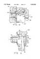
- FIGS. 3 and 4which show a prior art "banjo" fitting, a typical banjo fitting is comprised of body 102 through which bolt 103 is assembled. The combination of body 102 and bolt 103 is then assembled to port 101. Sealing of the body/bolt assembly is accomplished with copper (typically) washers 104 and 105, which are placed each side of body 102. Large torques (applied in the radial direction of arrow T of FIG. 4) are employed to obtain a seal between components, which sometimes cannot be sealed. A common failure of this assembly is to snap the bolt or strip the threads of the port while striving to attain sealing contact.
- the "banjo" fittingsare useful because of their inherent assembly benefits in situations where time taken to assemble and ease of access to components are important considerations. "Banjo" fittings are assembled from the front, and assembly can be effected with power tools. This is not true of other fittings which perform the function served by "banjo" fittings, that of supplying fluid to a component through a 90 degree change of direction or other similar reorientation of fluid flow. This change of fluid flow is accomplished by connecting a tube or similar fluid conduit at a transverse orientation relative to the axis of the bolt/body assembly. This transverse connection is often accomplished with a tube-to-port fitting.
- FIG. 4A drawing of an assembled prior art "banjo" fitting is shown in FIG. 4, where body 102, shown in partial cut-away, is recessed internally to create flow chamber 124 for pressurized fluid.
- a recessing operationis required to be done to body 102, rather than in bolt 103, in order to retain as much tensile strength in bolt 103 as possible. If bolt 103 were reduced in diameter to create a flow chamber, insufficient material would remain in bolt 103 to withstand the massive assembly torques required to obtain a seal.
- the recessing operation required for body 102is expensive and difficult to control.
- bolt 103must be made of relatively high tensile material in order to resist tensile failure due to high torques, and such materials are hard to machine which further complicates the manufacture of prior art "banjo" fittings.
- Another probleminvolves the orientation of the o-ring. Positioned in both the tapered area and the parallel interface, the o-ring is deformed during the assembly operation into a kidney-like shape, with a portion remaining in the relatively large tapered portion of the port. When the o-ring takes a set over time, it will be incapable of movement within the pocket, being trapped by the tapered portion. In order for an o-ring to work properly, it must be capable of moving in response to pressure differentials. Therefore, the improper positioning of the o-ring in the port interface tends to prevent the o-ring from moving and thus degrades long term performance of the fitting.
- the transverse tubing of the banjois conventionally connected by brazing.
- the brazing operationrequires that the complete banjo assembly, including the transverse tube, be put in the brazing furnace.
- the transverse tubeis several time larger than the other banjo components, brazing the tube requires much more room inside the brazing furnace.
- the increased amount of furnace space neededincreases the manufacturing cost of the banjo assembly.
- coatingssuch as zinc plating tend to flash off in the brazing furnace, the components must be assembled and brazed in their uncoated condition. This requires that the banjo assembly be coated subsequent to the brazing operation to provide a corrosion resistant assembly. Requiring these two processing steps greatly increases the cost of manufacture of the banjo, often doubling or tripling the cost of the banjo components themselves.
- a further needis for an improved hydraulic coupling which includes secondary seals.
- the present inventioninvolves a crimped tube-to-port fitting which creates a metal-to-metal primary seal and allows for an elastomeric secondary seal. This avoids the necessity of forming threads or performing a brazing operation while providing a highly leak resistant hydraulic coupling. Also, the present invention allows the fitting components to be coated for corrosion resistance previous to assembly of the components. A compression ring is forced into sealing contact with the surface of the port by crimping a collar of the port, driving the ring into the interface.
- the crimped tube-to-port fittingmay also be utilized for connecting the tube to the bolt/body assembly of a banjo fitting.
- the elastic deformation of mating componentsis preferred because the elastic memory of the material (either metal or rubber and the like) imparts a continuous sealing force. In comparison, plastic deformation of the material, which permanently deforms the fitting components, imparts no additional sealing force. Both metals and rubber type materials are subject to both forms of deformation, as metal material may be plasticly deformed by high torque when assembled while elastic materials may be plasticly deformed by setting over time.
- Embodiments of the present inventionimpart multiple seals to the port interface, and use elastic memory of metallic components in the interface where possible. This is attained by the use of elastic components in those instances where such is possible or desireable in conjunction with abutting tapered metallic surfaces which allow for the generation of an interface the integrity of which is enhanced by elastic memory. With ports made of softer materials, a metallic component having a complementary taper or a resin polymer component may be used to create a contact seal of similar integrity.
- the acute tapered metallic surfacesprovides a high unit loading which ameliorates the need for the expensive materials needed for receiving the high torques required with prior art fitting components.
- the present inventionspecifically addresses the need for a hydraulic coupling utilizing components capable of being pre-coated prior to assembly.
- the resulting interface between the tube and the portresists the vibration, heating and cooling cycles, pressure pulses, flexure, and other operating conditions of the brake, power steering, and air conditioning systems used by the automotive industries.
- the fitting of the present inventionincludes multiple seals in the interface, each having different characteristics in order to seal in both low and high pressures under aggressively destructive conditions. Also, the present invention may be efficiently and economically implemented.
- the present inventionutilizes tapered surfaces at its interfaces to invoke the elastic memory of the components of the assembly, and using metal-to-metal seals with elastomeric seals.
- the inventive fittingrequires associative forces to create the necessary seal between the metal surfaces.
- the present inventionutilizes the crimp collar as the component part for applying the required associative forces.
- the assembly forceis created by the use of a press which rolls, coins, swedges, or otherwise deforms the collar over the assembled components, capturing all the components in their assembled condition.
- the elastomeric sealsare placed within a pocket of larger cross-sectional area than that of the elastomer seal itself so as not to interfere with the metal-to-metal seals.
- the crimp collaralso provides a separation of the point of application of the associative forces from the sealing surfaces in order to offer better resistance to flexural forces and vibration.
- the resulting designmay be easily translated to a variety of sizes of tubing and fitting components for use in many hydraulic fields.
- One object of the present inventionis to provide an improved hydraulic coupling which utilizes the elastic properties of the materials.
- an objectis to provide an improved hydraulic coupling which does not excessively deform sealing rings in the coupling.
- a further objectis to provide an improved hydraulic coupling which includes secondary seals.
- An additional objectis to provide an improved hydraulic coupling for refrigerant systems which includes metal-to-metal seals.
- a still further objectis to provide an improved hydraulic coupling which minimizes the number of potential leak paths.
- Yet another objectis to provide an improved hydraulic coupling which requires less torque for assembly.
- FIG. 1is a side view, in partial cross section, of a prior art tube-to-port coupling before assembly
- FIG. 2is a side view, in partial cross section, of a prior art tube-to-port coupling assembled
- FIG. 3is a side view, in partial cross section, of a prior art "banjo" coupling before assembly
- FIG. 4is a side view, in partial cross section, of a prior art "banjo" coupling assembled
- FIG. 5is a side view, in partial cross section, of a tube-to-port coupling before assembly
- FIG. 6is a side view, in partial cross section, of the tube-to-port coupling of FIG. 5 assembled
- FIG. 7is an enlarged sectional view of the abutting portions of the port, nut, and tube of FIG. 6;
- FIG. 8is a side view, in partial cross-section, of a transverse hydraulic coupling before assembly
- FIG. 9is a side view, in partial cross-section, of the coupling of FIG. 8 assembled without o-rings;
- FIG. 10is a side view, in partial cross-section of the coupling of FIG. 8 assembled with o-rings;
- FIG. 11is a side view, in partial cross-section, of the coupling of FIG. 8 showing a transverse passageway;
- FIG. 12is a side view, in partial cross-section, of a second embodiment of the tube-to-port coupling
- FIG. 13is a side view, in partial cross-section, of a hydraulic coupling of the present invention previous to crimping;
- FIG. 14is an enlarged cross-sectional view of the tube assembly previous to crimping
- FIG. 15is a side view, in partial cross-section, of the hydraulic coupling of FIG. 13 after crimping;
- FIG. 16is and exploded view, in partial cross-section, of the tube assembly of FIG. 13.
- the present inventionrelates to hydraulic couplings, and particularly to couplings which utilize the elastic properties of materials, for example metals or o-rings, to form sealing contact between mating components.
- Port body 201contains an internally defined passageway for fluid communication, and has internal threads 202 for engaging tube nut 204.
- Tube nut 204is disposed over expanded portion 207 of tube 203 and includes an end having a relatively thin wall or rim 208.
- shoulder portion 211 of nut 204abuts transition portion 210 of tube 203.
- Thin wall 208may include a taper to match tapered surface 215 of port 201, although such a taper is not necessary to practice the present invention.
- Thin wall 208 of nut 204is designed to conform with tapered surface 215 at the bottom of port 201 during assembly, and impinges on the outside of expanded portion 207 of tube 203.
- o-ring 209may be included for additional sealing security where desired.
- o-ringsare not acceptable components in hydraulic or gas systems, and the coupling functions properly either with or without o-ring 209. Where no such restriction on the use of o-rings exists, then the use of o-ring 209 will render the assembly even more reliable in the long term.
- Tube nut 204is connected to port 201 by the engagement of external threads 205 of nut 204 with internal threads 202 of port 201.
- lip 206 on expanded portion 207 of tube 203contacts tapered surface 215 ahead of any contact with o-ring 209. This ensures that there will be a visible leak from the assembly in the event that wrench tightening has not occurred.
- shoulder portion 211forces expanded portion 207 into port 201 causing lip 206 to contact and deform on tapered surface 215 creating a metal-to-metal interface between lip 206 and tapered surface 215 which itself seals against pressure.
- o-ring 209is brought into contact with tapered surface 215, and finally, thin wall 208 of tube nut 204 contacts tapered surface 215.
- thin wall 208 of tube nut 204conforms with tapered surface 215 in port 201, and is driven down into contact with expanded portion 207 of tube 203.
- the engagement of expanded portion 207 and nut 204forms a second metal-to-metal seal as a back-up to the seal between lip 206 and tapered surface 215.
- 0-ring 209which occupies the space between the metal-to-metal seals of the assembly, sits in pocket 216 so formed and constitutes a third seal in the assembly.
- seal 212is formed between lip 206 and tapered surface 215, additional seals 213 and 214 are formed between thin wall 208 and both tapered surface 215 and expanded portion 207, respectively, and another seal is formed by o-ring 209. Additional benefits are also derived from the presence of metal-to-metal seals when used with air conditioning refrigerants which are capable of permeation through elastomeric seals. The existence of metal-to-metal seals prevents even the slightest permeation leaks, and, even if the metal seals failed, they would significantly slow the permeation rate of refrigerant through the interface.
- the tube to port coupling of FIGS. 5-7is assembled by inserting nut 204 into port 201 and threadably engaging threads 205 of nut 204 with threads 202 of port 201. Continuing to rotate nut 204, threads 205 and 202 engage until lip 206 contacts tapered surface 215. With manual or hand tightening of nut 204, o-ring 209 would not yet be in contact with tapered surface 215, and a leak would be apparent if pressurized fluid was introduced through the interface. By further tightening using a wrench, nut 204 may be rotated so that lip 206 is deformed on tapered surface 215. Also, optional o-ring 209 is positioned in sealing contact with tapered surface 215.
- thin wall 208comes into contact with tapered surface 215 and is thus deformed and forms a seal on tapered surface 215. Finally, thin wall 208 is urged inwardly until it is deformed into sealing contact with expanded portion 207.
- the torque required to deform lip 206 and bring nut 204 into sealing contactis relatively small in comparison to the torques required with prior art fittings because the narrow taper of surface 215 facilitates deformation of lip 206.
- the unit loading of the mating components which is generated during assemblyis exceptionally high, enhancing the potential for a reliable seal.
- the nature of a taperis such that elastic memory is invoked between mating tapered surfaces, thereby ensuring long-term integrity of the interface, even under the most aggressive influences such as vibration, heating and cooling, impulse, flexure, etc.
- tube 203initially has an outer diameter which is greater than the inner diameter of nut 204.
- the couplingis formed by first compacting an end of the tube and placing the nut on the compacted portion. Next, the compacted tube end is again expanded to an extent so that the nut is captured on the tube, and the lip is formed.
- the difference between the compacted portion and the outside diameter of the tubemay be as little as a few thousandths of an inch, however, this differential is sufficient to capture the nut.
- the differential between the outer diameter of the tube and the outer diameter of the compacted portion of the tubeis in the range of 0.010 inches to 0.050 inches, more particularly in the range of 0.015 inches to 0.030 inches, and specifically about 0.020 inches.
- a transverse hydraulic couplingwhich resulted from consideration of the same requirements, includes a tapered metal-to-metal interface backed up by optional o-rings which are shown in FIGS. 8-11.
- the transverse couplingcomprises port 301, body 304, and bolt 309.
- Port 301has internal threads 302 and a tapered surface 303 into which fits external taper 305 of body 304.
- Body 304defines axial passageway 306 which is in fluid communication with port 301, and includes annular surface 308 facing port 301.
- At the distal end of body 304is an internal taper 307 which mates with external taper 319 on the bolt 309.
- Bolt 309has surfaces 311 and 317 which may support optional o-rings 322 and 323 in pockets 327 and 328, respectively.
- Pocket 327is defined between surface 311, tapered surface 303, and annular surfaces 312 and 308 of bolt 309 and body 304, respectively.
- Pocket 328is defined between extension 316, surface 317, annular surface 318, and tapered surface 307.
- o-ring 323is first placed on surface 317.
- Bolt 309is then assembled into body 304 and o-ring 322 is placed on surface 311.
- the fitting formed by bolt 309 and body 304is held together by o-ring 323, which is an advantage during final attachment to port 301.
- the internal fluid conduit provided by body 304is defined by internal cylindrical wall 306 and bolt 309. Specifically, the conduit includes chamber 326, aperture 315, and bore 321.
- Chamber 326is defined by wall 306 and outer surface 314 of bolt 309, and also may be further defined by extensions 313 and 316 of bolt 309.
- Bore 321is in fluid communication with chamber 326 by virtue of aperture 315 which is located on outer surface 314.
- another passageway 332, which is transverse to bore 321is defined by arm 331 of body 309. Passageway 332 is in fluid communication with chamber 326 to thereby provide a fluid conduit for flow from a tube, or other device which may be attached to arm 331, to port 301.
- FIG. 12shows another embodiment of the tube-to-port coupling.
- tube 203'does not include a lip, rather, expanded portion 207' extends into port 201 and provides a seating surface for o-ring 209.
- Expanded portion 207does not extend to contact tapered surface 215, but nut 204 presses o-ring 209 into sealing contact with tapered surface 215.
- sealsare formed by o-ring 209 and thin walled portion 208.
- thin wall 208presses against o-ring 209 and thus forces o-ring 209 into sealing contact with tapered surface 215 of port 201 until a sealing contact is formed between thin wall 208 and expanded portion 207'.
- this embodimentperforms similarly to the embodiment shown in FIGS. 5-7 except that instead of a seal at 212 of FIG. 7, a gap 222 remains between expanded portion 207' and tapered surface 215.
- the connector portions of the hydraulic couplingsare made of material such as mild steel, stainless steel, monel, titanium, aluminum, brass, and various machinable alloys as well as certain plastics such as resin polymer material.
- the conduit portions of the hydraulic couplingi.e., tube 203 and body 304) are made of material such as copper, brass, mild steel, stainless steel, titanium, aluminum, and various malleable/machinable alloys as well as certain plastics such as resin polymer material.
- the angle of the tapered surfaces of the coupling interfacesis in the range of 5° to 45°, more particularly in the range of 10° to 30°, and preferably about 15°.
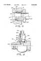
- FIG. 13shows transverse coupling 401 previous to the crimping operation.
- Transverse coupling 401includes bolt 402 and conduit body 403 which are similar to the transverse coupling of FIGS. 8-11.
- the present inventionutilizes transverse port portion 404 to provide an attachment for transverse tube 405.
- Port portion 404includes tapered surface 406 and may be formed integrally as part of conduit body 403, or alternatively may be separately formed then attached to conduit body 403, e.g., by brazing. However, such attachment may be accomplished previous to the crimping attachment of tube 405 to port portion 404.
- Tapered surface 406receives the end of tube 405, sealing ring 407 (in the form of an o-ring), and compression ring 408.
- port portion 404includes crimp collar 409 which extends beyond compression ring 408.
- Tube 405has a specially formed end which includes tapered lip 410, seating portion 411, and tube upset 412.
- Tapered lip 410has an outer surface which generally corresponds to the taper of tapered surface 406.
- Seating portion 411is generally cylindrical and in conjunction with compression ring 408 and tapered surface 406 defines pocket 413. Pocket 413 is significantly larger in cross-sectional area than sealing ring 407 and provides a location for sealing ring 407.
- Seating portion 411is expanded having a larger diameter than the non-banjo connected end of tube 405, with tube upset 412 being the portion connecting expanded seating portion 411 with the main portion of tube 405.
- Compression ring 408includes an annular body having end face 415 defining a boundary of pocket 413, tapered seat 416 generally corresponding to the taper of tapered surface 406, and reverse taper 417 for accommodating crimp collar 409 in the final assembly process.
- Tube upset 412has an outer surface which is angled to correspond with internal angled seat 414 of compression ring 408 so that an additional seal may be formed between the outside of tube 405 and the inside of compression ring 408.
- Compression ring 408may be made from material such as mild steel, stainless steel, monel, titanium, aluminum, brass, and various machinable alloys as well as certain plastics such as resin polymer material.
- FIG. 15shows collar 409 after being crimped over compression ring 408 by either a swaging, rolling, coining, or similar process.
- Collar 409is pressed into reverse taper 417 to drive compression ring 408 between tapered surface 406 of port portion 404 and seating surface 411.
- This crimping of collar 409creates metal-to-metal seals between: (1) tapered lip 410 of tube 405 and tapered surface 406 of port portion 404, (2) tapered seat 416 of compression ring 408 and tapered surface 406 of port portion 404, and (3) tube upset 412 of tube 405 and internal angled seat 414 of compression ring 408.
- compression ring 408may first be assembled into port portion 404 prior to crimping collar 409. Further, sealing ring 407 is located in pocket 413 to provide an elastomeric secondary seal to respond to pressure differentials across the interface should the multiple metal-to-metal seals fail.
Landscapes
- Engineering & Computer Science (AREA)
- General Engineering & Computer Science (AREA)
- Mechanical Engineering (AREA)
- Gasket Seals (AREA)
- Joints With Pressure Members (AREA)
- Non-Disconnectible Joints And Screw-Threaded Joints (AREA)
Abstract
Description
Claims (19)
Priority Applications (11)
| Application Number | Priority Date | Filing Date | Title |
|---|---|---|---|
| US08/269,841US5533765A (en) | 1991-10-25 | 1994-07-01 | Crimped tube-to-port hydraulic fittings |
| EP95924748AEP0769115B1 (en) | 1994-07-01 | 1995-06-29 | Crimped tube-to-port hydraulic fittings |
| PCT/US1995/008183WO1996001387A1 (en) | 1994-07-01 | 1995-06-29 | Crimped tube-to-port hydraulic fittings |
| AU29136/95AAU2913695A (en) | 1994-07-01 | 1995-06-29 | Crimped tube-to-port hydraulic fittings |
| JP8503916AJPH11500514A (en) | 1994-07-01 | 1995-06-29 | Liquid piping connection device |
| KR1019970700002AKR100333477B1 (en) | 1994-07-01 | 1995-06-29 | Corrugated Structure Fluid Fitting |
| ES95924748TES2103245T1 (en) | 1994-07-01 | 1995-06-29 | HYDRAULIC COUPLING. |
| DE69509655TDE69509655T2 (en) | 1994-07-01 | 1995-06-29 | HYDRAULIC PIPE / SLEEVE PRESS CONNECTION |
| DE0769115TDE769115T1 (en) | 1994-07-01 | 1995-06-29 | HYDRAULIC PIPE / SLEEVE PRESS CONNECTION |
| BR9508370ABR9508370A (en) | 1994-07-01 | 1995-06-29 | Hydraulic coupling |
| CA002194242ACA2194242C (en) | 1994-07-01 | 1995-06-29 | Crimped tube-to-port hydraulic fittings |
Applications Claiming Priority (4)
| Application Number | Priority Date | Filing Date | Title |
|---|---|---|---|
| US78240991A | 1991-10-25 | 1991-10-25 | |
| PCT/US1992/009035WO1993008423A1 (en) | 1991-10-25 | 1992-10-22 | Hydraulic port fittings |
| US08/230,972US5516156A (en) | 1991-10-25 | 1994-04-21 | Hydraulic port fittings |
| US08/269,841US5533765A (en) | 1991-10-25 | 1994-07-01 | Crimped tube-to-port hydraulic fittings |
Related Parent Applications (1)
| Application Number | Title | Priority Date | Filing Date |
|---|---|---|---|
| US08/230,972Continuation-In-PartUS5516156A (en) | 1991-10-25 | 1994-04-21 | Hydraulic port fittings |
Publications (1)
| Publication Number | Publication Date |
|---|---|
| US5533765Atrue US5533765A (en) | 1996-07-09 |
Family
ID=23028875
Family Applications (1)
| Application Number | Title | Priority Date | Filing Date |
|---|---|---|---|
| US08/269,841Expired - LifetimeUS5533765A (en) | 1991-10-25 | 1994-07-01 | Crimped tube-to-port hydraulic fittings |
Country Status (10)
| Country | Link |
|---|---|
| US (1) | US5533765A (en) |
| EP (1) | EP0769115B1 (en) |
| JP (1) | JPH11500514A (en) |
| KR (1) | KR100333477B1 (en) |
| AU (1) | AU2913695A (en) |
| BR (1) | BR9508370A (en) |
| CA (1) | CA2194242C (en) |
| DE (2) | DE69509655T2 (en) |
| ES (1) | ES2103245T1 (en) |
| WO (1) | WO1996001387A1 (en) |
Cited By (18)
| Publication number | Priority date | Publication date | Assignee | Title |
|---|---|---|---|---|
| US5833281A (en)* | 1995-06-09 | 1998-11-10 | Hoerbiger Gmbh | Fastening structure for a fluid plug-type connector with a connection bore |
| US5992898A (en)* | 1997-08-21 | 1999-11-30 | Echlin, Inc. | Quick-connect assembly and method of manufacture |
| US6109659A (en)* | 1998-06-12 | 2000-08-29 | Power Transmission Technology, Inc. | Hydrostatic rotary union |
| EP1075620A4 (en)* | 1999-03-05 | 2002-01-23 | Peter B Hutton | Stabilized mounting assembly with integral block module and manifold/transmitter module |
| EP0945693A3 (en)* | 1998-03-24 | 2003-01-08 | Unicair Limited | Method and apparatus for sealing a refrigeration system |
| US20030062721A1 (en)* | 2001-09-28 | 2003-04-03 | Masayoshi Usui | Ring joint, connection structure for connecting piping and ring joint, and method of connecting ring joint and piping |
| US6595558B2 (en)* | 2000-05-29 | 2003-07-22 | Usui Kokusai Sangyo Kaisha Limited | High-pressure metal pipe with connection head, method of forming the head and connection washer for the connection head |
| US6598908B1 (en) | 2000-06-16 | 2003-07-29 | Marshall W. Wosik | Hydraulic fitting |
| US20040212193A1 (en)* | 2002-10-08 | 2004-10-28 | Johnstone Ian David | Connector |
| US20060208484A1 (en)* | 2005-03-11 | 2006-09-21 | Swift Jonathan C | Quick connect coupling with disconnect lock |
| US20070001450A1 (en)* | 2005-03-11 | 2007-01-04 | Swift Jonathan C | Pressure activated disconnect lock coupling |
| US20070046026A1 (en)* | 2005-08-31 | 2007-03-01 | Wells Billy P | Tube-to-tube connection |
| US20100051848A1 (en)* | 2008-09-01 | 2010-03-04 | Siemens Aktiengesellschaft | Coupling element for connecting actuator to valve |
| EP2434190A3 (en)* | 2010-09-27 | 2015-10-14 | Hamilton Sundstrand Corporation | Refrigeration System Connection Fitting |
| US20150300505A1 (en)* | 2012-10-16 | 2015-10-22 | Schaeffler Technologies Gmbh & Co. Kg | Seal arrangement for a control valve |
| CN114473935A (en)* | 2022-03-22 | 2022-05-13 | 康姆兹科技(深圳)有限公司 | A multi-way tightening joint in the medical field |
| US11408790B2 (en)* | 2018-06-28 | 2022-08-09 | Ovh | Fluid circuit monitoring system for determining when to perform preventative maintenance |
| US11698153B2 (en) | 2021-09-24 | 2023-07-11 | Caterpillar Inc. | Fluid joint assembly adjustable from primary to backup sealing state and fluid connector for same |
Citations (46)
| Publication number | Priority date | Publication date | Assignee | Title |
|---|---|---|---|---|
| DE53477C (en)* | W. P. GlBSON in London, 15 Queen Street | Auxiliary control device for regulating the movement of the main control slide in water pressure elevators | ||
| US1515248A (en)* | 1918-05-18 | 1924-11-11 | Frederick M Furber | Spark plug and method of manufacturing the same |
| DE434908C (en)* | 1925-02-01 | 1926-10-05 | Abt Hoerder Ver | Procedure for laying pipe strings |
| AU250541A (en)* | 1941-08-13 | 1942-08-27 | Hallum Ferguson Robert | A device forthe resealing of traps under sanitary fixtures |
| US2332893A (en)* | 1942-05-07 | 1943-10-26 | Flex O Tube Company | Universal tube fitting |
| US2496149A (en)* | 1946-07-26 | 1950-01-31 | Harry Alter Company | Coupler |
| US2657077A (en)* | 1947-06-20 | 1953-10-27 | George V Woodling | Flareless sleeve connector having forward contractible ring end portion and rearwardspring fingers |
| US2687906A (en)* | 1949-01-26 | 1954-08-31 | Wagner Electric Corp | Swaged type metallic pipe fitting |
| GB718264A (en)* | 1950-11-14 | 1954-11-10 | Leslie Charles Bishop Ward | Improvements in or relating to joints for lead and like soft metal pipes |
| US2826438A (en)* | 1952-01-29 | 1958-03-11 | Gilbert T Lyon | Gland type fluid seal connection for conduits |
| US2942895A (en)* | 1956-07-13 | 1960-06-28 | L & L Mfg Company | Captive nut |
| US3003795A (en)* | 1959-08-12 | 1961-10-10 | L & L Mfg Company | Tube coupling having a resilient metal sealing sleeve |
| US3145035A (en)* | 1958-09-10 | 1964-08-18 | Weatherhead Co | Pipe coupling having a flexible sealing lip |
| US3151893A (en)* | 1960-05-25 | 1964-10-06 | L & L Mfg Company | Tube coupling |
| US3151896A (en)* | 1960-10-24 | 1964-10-06 | Imp Eastman Corp | Rotationally adjustable fitting |
| US3201153A (en)* | 1961-05-15 | 1965-08-17 | Parker Hannifin Corp | Flareless tube coupling for plastic or metal tubing |
| US3219366A (en)* | 1962-02-20 | 1965-11-23 | Imp Eastman Corp | Reinforced fluid control fitting |
| US3315988A (en)* | 1960-08-04 | 1967-04-25 | Walterscheid Kg Jean | Orientable conduit connector |
| FR1507625A (en)* | 1966-01-07 | 1967-12-29 | Mannin Eng Ltd | Device for coupling a pipe to a fluid pump, valve, cylinder or other component |
| US3441293A (en)* | 1966-07-06 | 1969-04-29 | Luigi Bagnulo | Pipe coupling |
| US3451110A (en)* | 1966-10-03 | 1969-06-24 | Ford Motor Co | Spark plug |
| US3501171A (en)* | 1967-07-10 | 1970-03-17 | Alfred Morton Baron | Connector assembly for fluid conduits |
| US3560028A (en)* | 1968-01-19 | 1971-02-02 | Mitsui Petrochemical Ind | Pipe joint device |
| GB1227037A (en)* | 1969-02-28 | 1971-03-31 | ||
| US3615160A (en)* | 1969-11-03 | 1971-10-26 | Hynautic Inc | Tube and sealed joint assembly |
| US3858914A (en)* | 1973-07-25 | 1975-01-07 | Brass Craft Mfg Co | Transition pipe connection |
| US3940843A (en)* | 1974-12-16 | 1976-03-02 | R. E. Chapin Manufacturing Works, Inc. | Method of forming an extension tube assembly |
| US4009896A (en)* | 1976-05-10 | 1977-03-01 | General Motors Corporation | Quick connect coupling |
| DE2610775A1 (en)* | 1976-03-15 | 1977-09-22 | Ermeto Armaturen Gmbh | SWIVEL COUPLING FOR PIPE CONNECTION |
| US4214781A (en)* | 1978-09-05 | 1980-07-29 | Sealed Power Corporation | Pipe joint and method of assembly |
| DE3416702A1 (en)* | 1984-05-05 | 1985-11-21 | FAG Kugelfischer Georg Schäfer KGaA, 8720 Schweinfurt | Permanent connection between pipes, e.g. for hydraulic brake systems |
| US4606668A (en)* | 1984-03-19 | 1986-08-19 | Lemforder Metallwaren Ag. | Axial ball joint for articulated linkages in motor vehicles and method of fabricating same |
| US4693502A (en)* | 1972-08-10 | 1987-09-15 | Hans Oetiker | Pipe connection |
| GB2192247A (en)* | 1986-05-26 | 1988-01-06 | Usui Kokusai Sangyo Kk | Pipe coupling |
| EP0276483A1 (en)* | 1987-01-23 | 1988-08-03 | Behr GmbH & Co. | Tube joint, especially for a flat tube evaporator |
| GB2205373A (en)* | 1987-05-23 | 1988-12-07 | Mie Horo Co Ltd | Method of making piping joints and joining tool |
| GB2207722A (en)* | 1987-07-02 | 1989-02-08 | Bristol Bending Services Limit | Seals for use in sealing tube and pipe joints |
| US4848448A (en)* | 1987-12-28 | 1989-07-18 | Mccord Heat Transfer Corporation | Heat exchange assembly |
| US4934742A (en)* | 1988-01-27 | 1990-06-19 | Nwd International, Inc. | Hydraulic coupling |
| EP0412626A1 (en)* | 1989-08-11 | 1991-02-13 | Form Rite Limited | Hydraulic fitting |
| US5120084A (en)* | 1989-09-27 | 1992-06-09 | Usui Kokusai Sangyo Kaisha Limited | Connection structure for branching connector in high-pressure fuel rail |
| JPH04165191A (en)* | 1990-10-25 | 1992-06-10 | Toyoda Gosei Co Ltd | Eye joint |
| JPH04341682A (en)* | 1991-05-20 | 1992-11-27 | Hitachi Ltd | Pipe coupling |
| WO1993008423A1 (en)* | 1991-10-25 | 1993-04-29 | Nwd Manufacturing, Inc. | Hydraulic port fittings |
| JPH05141580A (en)* | 1991-11-15 | 1993-06-08 | Nippondenso Co Ltd | Pipe connective device |
| US5261705A (en)* | 1991-04-08 | 1993-11-16 | Toyota Jidosha Kabushiki Kaisha | Coupling for high pressure fluid |
- 1994
- 1994-07-01USUS08/269,841patent/US5533765A/ennot_activeExpired - Lifetime
- 1995
- 1995-06-29EPEP95924748Apatent/EP0769115B1/ennot_activeExpired - Lifetime
- 1995-06-29KRKR1019970700002Apatent/KR100333477B1/ennot_activeExpired - Fee Related
- 1995-06-29CACA002194242Apatent/CA2194242C/ennot_activeExpired - Fee Related
- 1995-06-29ESES95924748Tpatent/ES2103245T1/enactivePending
- 1995-06-29DEDE69509655Tpatent/DE69509655T2/ennot_activeExpired - Fee Related
- 1995-06-29BRBR9508370Apatent/BR9508370A/ennot_activeIP Right Cessation
- 1995-06-29WOPCT/US1995/008183patent/WO1996001387A1/enactiveIP Right Grant
- 1995-06-29DEDE0769115Tpatent/DE769115T1/enactivePending
- 1995-06-29AUAU29136/95Apatent/AU2913695A/ennot_activeAbandoned
- 1995-06-29JPJP8503916Apatent/JPH11500514A/enactivePending
Patent Citations (47)
| Publication number | Priority date | Publication date | Assignee | Title |
|---|---|---|---|---|
| DE53477C (en)* | W. P. GlBSON in London, 15 Queen Street | Auxiliary control device for regulating the movement of the main control slide in water pressure elevators | ||
| US1515248A (en)* | 1918-05-18 | 1924-11-11 | Frederick M Furber | Spark plug and method of manufacturing the same |
| DE434908C (en)* | 1925-02-01 | 1926-10-05 | Abt Hoerder Ver | Procedure for laying pipe strings |
| AU250541A (en)* | 1941-08-13 | 1942-08-27 | Hallum Ferguson Robert | A device forthe resealing of traps under sanitary fixtures |
| US2332893A (en)* | 1942-05-07 | 1943-10-26 | Flex O Tube Company | Universal tube fitting |
| US2496149A (en)* | 1946-07-26 | 1950-01-31 | Harry Alter Company | Coupler |
| US2657077A (en)* | 1947-06-20 | 1953-10-27 | George V Woodling | Flareless sleeve connector having forward contractible ring end portion and rearwardspring fingers |
| US2687906A (en)* | 1949-01-26 | 1954-08-31 | Wagner Electric Corp | Swaged type metallic pipe fitting |
| GB718264A (en)* | 1950-11-14 | 1954-11-10 | Leslie Charles Bishop Ward | Improvements in or relating to joints for lead and like soft metal pipes |
| US2826438A (en)* | 1952-01-29 | 1958-03-11 | Gilbert T Lyon | Gland type fluid seal connection for conduits |
| US2942895A (en)* | 1956-07-13 | 1960-06-28 | L & L Mfg Company | Captive nut |
| US3145035A (en)* | 1958-09-10 | 1964-08-18 | Weatherhead Co | Pipe coupling having a flexible sealing lip |
| US3003795A (en)* | 1959-08-12 | 1961-10-10 | L & L Mfg Company | Tube coupling having a resilient metal sealing sleeve |
| US3151893A (en)* | 1960-05-25 | 1964-10-06 | L & L Mfg Company | Tube coupling |
| US3315988A (en)* | 1960-08-04 | 1967-04-25 | Walterscheid Kg Jean | Orientable conduit connector |
| US3151896A (en)* | 1960-10-24 | 1964-10-06 | Imp Eastman Corp | Rotationally adjustable fitting |
| US3201153A (en)* | 1961-05-15 | 1965-08-17 | Parker Hannifin Corp | Flareless tube coupling for plastic or metal tubing |
| US3219366A (en)* | 1962-02-20 | 1965-11-23 | Imp Eastman Corp | Reinforced fluid control fitting |
| FR1507625A (en)* | 1966-01-07 | 1967-12-29 | Mannin Eng Ltd | Device for coupling a pipe to a fluid pump, valve, cylinder or other component |
| US3441293A (en)* | 1966-07-06 | 1969-04-29 | Luigi Bagnulo | Pipe coupling |
| US3451110A (en)* | 1966-10-03 | 1969-06-24 | Ford Motor Co | Spark plug |
| US3501171A (en)* | 1967-07-10 | 1970-03-17 | Alfred Morton Baron | Connector assembly for fluid conduits |
| US3560028A (en)* | 1968-01-19 | 1971-02-02 | Mitsui Petrochemical Ind | Pipe joint device |
| GB1227037A (en)* | 1969-02-28 | 1971-03-31 | ||
| US3615160A (en)* | 1969-11-03 | 1971-10-26 | Hynautic Inc | Tube and sealed joint assembly |
| US4693502A (en)* | 1972-08-10 | 1987-09-15 | Hans Oetiker | Pipe connection |
| US3858914A (en)* | 1973-07-25 | 1975-01-07 | Brass Craft Mfg Co | Transition pipe connection |
| US3940843A (en)* | 1974-12-16 | 1976-03-02 | R. E. Chapin Manufacturing Works, Inc. | Method of forming an extension tube assembly |
| DE2610775A1 (en)* | 1976-03-15 | 1977-09-22 | Ermeto Armaturen Gmbh | SWIVEL COUPLING FOR PIPE CONNECTION |
| US4009896A (en)* | 1976-05-10 | 1977-03-01 | General Motors Corporation | Quick connect coupling |
| US4214781A (en)* | 1978-09-05 | 1980-07-29 | Sealed Power Corporation | Pipe joint and method of assembly |
| US4606668A (en)* | 1984-03-19 | 1986-08-19 | Lemforder Metallwaren Ag. | Axial ball joint for articulated linkages in motor vehicles and method of fabricating same |
| DE3416702A1 (en)* | 1984-05-05 | 1985-11-21 | FAG Kugelfischer Georg Schäfer KGaA, 8720 Schweinfurt | Permanent connection between pipes, e.g. for hydraulic brake systems |
| US4776616A (en)* | 1986-05-26 | 1988-10-11 | Usui Kokusai Sangyo Kabushiki Kaisha | Coupling |
| GB2192247A (en)* | 1986-05-26 | 1988-01-06 | Usui Kokusai Sangyo Kk | Pipe coupling |
| EP0276483A1 (en)* | 1987-01-23 | 1988-08-03 | Behr GmbH & Co. | Tube joint, especially for a flat tube evaporator |
| GB2205373A (en)* | 1987-05-23 | 1988-12-07 | Mie Horo Co Ltd | Method of making piping joints and joining tool |
| GB2207722A (en)* | 1987-07-02 | 1989-02-08 | Bristol Bending Services Limit | Seals for use in sealing tube and pipe joints |
| US4848448A (en)* | 1987-12-28 | 1989-07-18 | Mccord Heat Transfer Corporation | Heat exchange assembly |
| US4934742A (en)* | 1988-01-27 | 1990-06-19 | Nwd International, Inc. | Hydraulic coupling |
| EP0412626A1 (en)* | 1989-08-11 | 1991-02-13 | Form Rite Limited | Hydraulic fitting |
| US5120084A (en)* | 1989-09-27 | 1992-06-09 | Usui Kokusai Sangyo Kaisha Limited | Connection structure for branching connector in high-pressure fuel rail |
| JPH04165191A (en)* | 1990-10-25 | 1992-06-10 | Toyoda Gosei Co Ltd | Eye joint |
| US5261705A (en)* | 1991-04-08 | 1993-11-16 | Toyota Jidosha Kabushiki Kaisha | Coupling for high pressure fluid |
| JPH04341682A (en)* | 1991-05-20 | 1992-11-27 | Hitachi Ltd | Pipe coupling |
| WO1993008423A1 (en)* | 1991-10-25 | 1993-04-29 | Nwd Manufacturing, Inc. | Hydraulic port fittings |
| JPH05141580A (en)* | 1991-11-15 | 1993-06-08 | Nippondenso Co Ltd | Pipe connective device |
Cited By (26)
| Publication number | Priority date | Publication date | Assignee | Title |
|---|---|---|---|---|
| US5833281A (en)* | 1995-06-09 | 1998-11-10 | Hoerbiger Gmbh | Fastening structure for a fluid plug-type connector with a connection bore |
| US5992898A (en)* | 1997-08-21 | 1999-11-30 | Echlin, Inc. | Quick-connect assembly and method of manufacture |
| EP0945693A3 (en)* | 1998-03-24 | 2003-01-08 | Unicair Limited | Method and apparatus for sealing a refrigeration system |
| US6109659A (en)* | 1998-06-12 | 2000-08-29 | Power Transmission Technology, Inc. | Hydrostatic rotary union |
| US6609730B1 (en) | 1999-03-05 | 2003-08-26 | Century Industries Company | Stabilized mounting assembly with integral block module and manifold/transmitter module |
| EP1075620A4 (en)* | 1999-03-05 | 2002-01-23 | Peter B Hutton | Stabilized mounting assembly with integral block module and manifold/transmitter module |
| US6595558B2 (en)* | 2000-05-29 | 2003-07-22 | Usui Kokusai Sangyo Kaisha Limited | High-pressure metal pipe with connection head, method of forming the head and connection washer for the connection head |
| US7032934B2 (en) | 2000-06-16 | 2006-04-25 | Wosik Marshall W | Hydraulic fitting |
| US6598908B1 (en) | 2000-06-16 | 2003-07-29 | Marshall W. Wosik | Hydraulic fitting |
| US20040036288A1 (en)* | 2000-06-16 | 2004-02-26 | Wosik Marshall W. | Hydraulic fitting |
| KR100844928B1 (en)* | 2001-09-28 | 2008-07-09 | 우수이 고쿠사이 산교 가부시키가이샤 | Eyejoint, Structure of jointing pipe with the same and Method of jointing pipe with the same |
| US20030062721A1 (en)* | 2001-09-28 | 2003-04-03 | Masayoshi Usui | Ring joint, connection structure for connecting piping and ring joint, and method of connecting ring joint and piping |
| US6851723B2 (en)* | 2001-09-28 | 2005-02-08 | Usui Kokusai Sangyo Kaisha, Ltd. | Ring joint, connection structure for connecting piping and ring joint, and method of connecting ring joint and piping |
| US20040212193A1 (en)* | 2002-10-08 | 2004-10-28 | Johnstone Ian David | Connector |
| US7469933B2 (en) | 2005-03-11 | 2008-12-30 | The Gates Corporation | Quick connect coupling with disconnect lock |
| US20070001450A1 (en)* | 2005-03-11 | 2007-01-04 | Swift Jonathan C | Pressure activated disconnect lock coupling |
| US20060208484A1 (en)* | 2005-03-11 | 2006-09-21 | Swift Jonathan C | Quick connect coupling with disconnect lock |
| US7533907B2 (en) | 2005-03-11 | 2009-05-19 | The Gates Corporation Ip Law Dept. | Pressure activated disconnect lock coupling |
| US20070046026A1 (en)* | 2005-08-31 | 2007-03-01 | Wells Billy P | Tube-to-tube connection |
| US20100051848A1 (en)* | 2008-09-01 | 2010-03-04 | Siemens Aktiengesellschaft | Coupling element for connecting actuator to valve |
| US8136788B2 (en)* | 2008-09-01 | 2012-03-20 | Siemens Aktiengesellschaft | Coupling element for connecting actuator to valve |
| EP2434190A3 (en)* | 2010-09-27 | 2015-10-14 | Hamilton Sundstrand Corporation | Refrigeration System Connection Fitting |
| US20150300505A1 (en)* | 2012-10-16 | 2015-10-22 | Schaeffler Technologies Gmbh & Co. Kg | Seal arrangement for a control valve |
| US11408790B2 (en)* | 2018-06-28 | 2022-08-09 | Ovh | Fluid circuit monitoring system for determining when to perform preventative maintenance |
| US11698153B2 (en) | 2021-09-24 | 2023-07-11 | Caterpillar Inc. | Fluid joint assembly adjustable from primary to backup sealing state and fluid connector for same |
| CN114473935A (en)* | 2022-03-22 | 2022-05-13 | 康姆兹科技(深圳)有限公司 | A multi-way tightening joint in the medical field |
Also Published As
| Publication number | Publication date |
|---|---|
| DE769115T1 (en) | 1998-04-09 |
| CA2194242C (en) | 2008-09-23 |
| JPH11500514A (en) | 1999-01-12 |
| DE69509655T2 (en) | 1999-12-30 |
| KR100333477B1 (en) | 2002-10-19 |
| CA2194242A1 (en) | 1996-01-18 |
| AU2913695A (en) | 1996-01-25 |
| EP0769115B1 (en) | 1999-05-12 |
| WO1996001387A1 (en) | 1996-01-18 |
| BR9508370A (en) | 1997-11-04 |
| EP0769115A1 (en) | 1997-04-23 |
| ES2103245T1 (en) | 1997-09-16 |
| DE69509655D1 (en) | 1999-06-17 |
Similar Documents
| Publication | Publication Date | Title |
|---|---|---|
| US5516157A (en) | Hydraulic port fittings | |
| US5533765A (en) | Crimped tube-to-port hydraulic fittings | |
| US5489127A (en) | Mounting apparatus with reduced resistance bead seal | |
| US5529349A (en) | Mounting apparatus with reduced resistance bead seal | |
| US7032934B2 (en) | Hydraulic fitting | |
| US5997049A (en) | Adjustable leak-tight coupling system | |
| US6375232B1 (en) | Bi-metallic union fitting for use in threaded ports | |
| US4934742A (en) | Hydraulic coupling | |
| US5110160A (en) | High pressure port fitting system | |
| US7195283B2 (en) | Self-centering tubular connection | |
| US6729659B2 (en) | Flare fitting assembly with metal-to-metal line seal | |
| KR20220145404A (en) | pipe joint | |
| CA2513827C (en) | Straight thread adjustable port end | |
| US6123317A (en) | Coupling | |
| EP3885623B1 (en) | A reversible brake tube connector | |
| US7159906B1 (en) | Methods and apparatus for flange sealing | |
| US5115550A (en) | Adjustable O-ring port fitting for a hydraulic coupling | |
| US5197769A (en) | Adjustable O-ring port fitting for a hydraulic coupling | |
| US3850456A (en) | Lip seal fittings | |
| MXPA97000201A (en) | Rubber hydraulic connections of acompue pipe | |
| EP0326292B1 (en) | Hydraulic coupling | |
| WO1998046924A1 (en) | Tubing joints and methods for attachment of tubing to valves and extrusions | |
| JP2003148663A (en) | Seal mechanism for fluid and pipe fitting structure using seal structure |
Legal Events
| Date | Code | Title | Description |
|---|---|---|---|
| AS | Assignment | Owner name:NWD INTERNATIONAL, INC., MICHIGAN Free format text:ASSIGNMENT OF ASSIGNORS INTEREST;ASSIGNORS:WILLIAMSON, NIGEL D.L.;NICHOLS, WARREN J.;REEL/FRAME:007298/0278 Effective date:19940630 | |
| STCF | Information on status: patent grant | Free format text:PATENTED CASE | |
| AS | Assignment | Owner name:UNITED BANK & TRUST, MICHIGAN Free format text:SECURITY AGREEMENT;ASSIGNOR:PILOT INDUSTRIES, INC.;REEL/FRAME:008283/0459 Effective date:19961220 | |
| AS | Assignment | Owner name:PILOT INDUSTRIES, INC., MICHIGAN Free format text:AGREEMENT;ASSIGNOR:NWD INTERNATIONAL, INC.;REEL/FRAME:008489/0607 Effective date:19961107 | |
| AS | Assignment | Owner name:PILOT INDUSTRIES, INC., MICHIGAN Free format text:AGREEMENT;ASSIGNOR:NWD INTERNATIONAL, INC.;REEL/FRAME:008412/0697 Effective date:19961107 | |
| AS | Assignment | Owner name:NBD BANK, MICHIGAN Free format text:SECURITY INTEREST;ASSIGNOR:PILOT INDUSTRIES, INC.;REEL/FRAME:008512/0093 Effective date:19970328 | |
| FEPP | Fee payment procedure | Free format text:PAT HLDR NO LONGER CLAIMS SMALL ENT STAT AS SMALL BUSINESS (ORIGINAL EVENT CODE: LSM2); ENTITY STATUS OF PATENT OWNER: LARGE ENTITY | |
| AS | Assignment | Owner name:PILOT INDUSTRIES, INC., MICHIGAN Free format text:RELEASE OF COLLATERAL FROM SECURITY INTEREST;ASSIGNOR:BANK ONE, MICHIGAN (FORMERLY NBD BANK);REEL/FRAME:010425/0360 Effective date:19991123 | |
| AS | Assignment | Owner name:BANK OF AMERICA, N.A., ILLINOIS Free format text:SECURITY INTEREST;ASSIGNOR:PILOT INDUSTRIES, INC.;REEL/FRAME:010485/0469 Effective date:19991124 | |
| FPAY | Fee payment | Year of fee payment:4 | |
| AS | Assignment | Owner name:RATHBURGER, DEBORAH, VICE PRESIDENT, ILLINOIS Free format text:PARTIAL RELEASE PATENT COLLATERAL SECURITY INTEREST.;ASSIGNOR:PILOT INDUSTRIES, INC.;REEL/FRAME:010849/0377 Effective date:20000517 | |
| AS | Assignment | Owner name:CERBERUS PILOT HOLDINGS, LLC, NEW YORK Free format text:SECURITY AGREEMENT;ASSIGNORS:PILOT INDUSTRIES, INC.;CERBERUS PILOT ACQUISITION, LLC;REEL/FRAME:013727/0582 Effective date:20021231 | |
| AS | Assignment | Owner name:MARTINREA INDUSTRIES INC., MICHIGAN Free format text:CHANGE OF NAME;ASSIGNOR:PILOT INDUSTRIES, INC.;REEL/FRAME:013532/0085 Effective date:20030207 | |
| AS | Assignment | Owner name:MARTINREA INDUSTRIES, INC., CANADA Free format text:PAYOFF, TERMINATION AND RELEASE;ASSIGNOR:CEBERUS PILOT HOLDINGS, LLC;REEL/FRAME:014446/0375 Effective date:20030627 | |
| FEPP | Fee payment procedure | Free format text:PAYOR NUMBER ASSIGNED (ORIGINAL EVENT CODE: ASPN); ENTITY STATUS OF PATENT OWNER: LARGE ENTITY | |
| FPAY | Fee payment | Year of fee payment:8 | |
| FPAY | Fee payment | Year of fee payment:12 |