US5533708A - Medical coupling site valve body - Google Patents
Medical coupling site valve bodyDownload PDFInfo
- Publication number
- US5533708A US5533708AUS08/378,506US37850695AUS5533708AUS 5533708 AUS5533708 AUS 5533708AUS 37850695 AUS37850695 AUS 37850695AUS 5533708 AUS5533708 AUS 5533708A
- Authority
- US
- United States
- Prior art keywords
- diaphragm
- coupling site
- valve element
- male luer
- recited
- Prior art date
- Legal status (The legal status is an assumption and is not a legal conclusion. Google has not performed a legal analysis and makes no representation as to the accuracy of the status listed.)
- Expired - Lifetime
Links
Images


Classifications
- A—HUMAN NECESSITIES
- A61—MEDICAL OR VETERINARY SCIENCE; HYGIENE
- A61M—DEVICES FOR INTRODUCING MEDIA INTO, OR ONTO, THE BODY; DEVICES FOR TRANSDUCING BODY MEDIA OR FOR TAKING MEDIA FROM THE BODY; DEVICES FOR PRODUCING OR ENDING SLEEP OR STUPOR
- A61M39/00—Tubes, tube connectors, tube couplings, valves, access sites or the like, specially adapted for medical use
- A61M39/02—Access sites
- A61M39/04—Access sites having pierceable self-sealing members
- A61M39/045—Access sites having pierceable self-sealing members pre-slit to be pierced by blunt instrument
- F—MECHANICAL ENGINEERING; LIGHTING; HEATING; WEAPONS; BLASTING
- F16—ENGINEERING ELEMENTS AND UNITS; GENERAL MEASURES FOR PRODUCING AND MAINTAINING EFFECTIVE FUNCTIONING OF MACHINES OR INSTALLATIONS; THERMAL INSULATION IN GENERAL
- F16L—PIPES; JOINTS OR FITTINGS FOR PIPES; SUPPORTS FOR PIPES, CABLES OR PROTECTIVE TUBING; MEANS FOR THERMAL INSULATION IN GENERAL
- F16L29/00—Joints with fluid cut-off means
- F16L29/005—Joints with fluid cut-off means joints with cut-off devices which can be perforated
- A—HUMAN NECESSITIES
- A61—MEDICAL OR VETERINARY SCIENCE; HYGIENE
- A61M—DEVICES FOR INTRODUCING MEDIA INTO, OR ONTO, THE BODY; DEVICES FOR TRANSDUCING BODY MEDIA OR FOR TAKING MEDIA FROM THE BODY; DEVICES FOR PRODUCING OR ENDING SLEEP OR STUPOR
- A61M39/00—Tubes, tube connectors, tube couplings, valves, access sites or the like, specially adapted for medical use
- A61M2039/0036—Tubes, tube connectors, tube couplings, valves, access sites or the like, specially adapted for medical use characterised by a septum having particular features, e.g. having venting channels or being made from antimicrobial or self-lubricating elastomer
- Y—GENERAL TAGGING OF NEW TECHNOLOGICAL DEVELOPMENTS; GENERAL TAGGING OF CROSS-SECTIONAL TECHNOLOGIES SPANNING OVER SEVERAL SECTIONS OF THE IPC; TECHNICAL SUBJECTS COVERED BY FORMER USPC CROSS-REFERENCE ART COLLECTIONS [XRACs] AND DIGESTS
- Y10—TECHNICAL SUBJECTS COVERED BY FORMER USPC
- Y10S—TECHNICAL SUBJECTS COVERED BY FORMER USPC CROSS-REFERENCE ART COLLECTIONS [XRACs] AND DIGESTS
- Y10S604/00—Surgery
- Y10S604/905—Aseptic connectors or couplings, e.g. frangible, piercable
Definitions
- the present inventionrelates to a coupling site for use in medical applications and more particularly, to a coupling site which includes a valve element and support structure for cooperation with a standard male luer lock having a male luer taper and a threaded locking collar.
- needle type injection siteshave the advantages of providing quick access for a fluid cannula as well as providing an access site which ensures a fluid-tight seal due to the small size of the aperture formed in the diaphragm by the needle.
- One proposed solution for eliminating needles at coupling sitesincludes providing a valve member having a slit for receiving a blunt cannula therethrough wherein the slit is biased to a closed position such that a fluid-tight seal is formed at the valve member when the cannula is removed.
- U.S. Pat. No. 4,765,588 to Atkinsondiscloses a valve for receiving the blunt end of a syringe and includes a slit diaphragm member mounted within a tubular body wherein the diaphragm is stretched in the area of the slit and moves in close to the tubular body as a luer taper portion of the syringe is inserted.
- the exterior wall of the body portionis dimensioned to be received within a threaded locking collar of the syringe surrounding the luer taper whereby an additional fluid-tight seal is formed with the valve.
- One such special cannulacontemplates providing a female luer connection for threadably engaging within the threaded locking collar of a male luer lock fitting on a syringe and further includes a specially configured blunt cannula having a tapered end for passing through the preslit septum of the valve.
- the housing holding the septummay be provided with threads for engaging coupling threads located interiorly of a shield surrounding the cannula.
- the outer diameter of the housingis formed larger than the inner diameter of the threaded collar on the syringe in order to provide sufficient space for the septum which expands outwardly into an annular space during insertion of a cannula.
- a medical coupling sitethat is usable with blunt cannula such as are provided by standard male luer lock fittings having a male luer taper surrounded by a threaded locking collar and in which the site is provided with a valve element and means for directly engaging the threads on the locking collar to form a mechanical connection. It should be noted that such a site is highly desirable in that standard dimensions for both male and female luer taper fittings have been recognized by both the American National Standards Institute, Inc. (ANSI) and by the International Organization for Standardization (ISO).
- ANSIAmerican National Standards Institute, Inc.
- ISOInternational Organization for Standardization
- fittings formed on the ends of syringes, as well as fittings for the majority fluid connections used in medical applications throughout the world, conform to the ANSI and ISO standards and a coupling site incorporating a valve for use with such standard fittingswould provide the advantage of allowing a positive mechanical connection to be formed at the coupling site as well as eliminate the need for the use of needles or special cannula to penetrate the valve element, and thus would overcome disadvantages associated with prior art coupling sites.
- Elimination of the need for a special cannula for use at the coupling sitewould also provide a cost advantage in that only the coupling site would need to be purchased and existing fittings could be used in conjunction with this site.
- One problem associated with providing a coupling site for use with a standard male luer lockresults from the limited space provided between the outer surface of the male luer taper and the inner surface of the threaded locking collar which makes it difficult to provide both a rigid locking surface on the outside of the fitting for engaging the locking collar and a flexible valve element of sufficient size and resilience to releasably accommodate the male luer taper.
- the Atkinson patent described abovedescribes a valve element which may be used with a luer fitting, but in which the outer surface of the elastomeric valve element is received in contact with the locking collar without the inclusion of any rigid member for engaging the threads within the collar.
- the PCT publication described abovediscloses an alternative approach to the same problem in that the adapter provided for attachment to a standard luer lock is provided with a locking collar which is larger than the locking collar provided on the male luer lock, thus permitting the coupling site to be constructed with an enlarged diameter to accommodate a sufficiently large septum for receiving a cannula having the desired diameter for providing sufficient flow through the site.
- valve elementwhich will both receive a luer taper as well as reliably reseal after the luer taper is removed.
- prior art valves for receiving a luer taperprovide a thick disk or septum, such as is disclosed in the above-noted PCT publication, wherein the disk or septum is formed with a sufficient amount of resilient material around the slit to close the slit when a cannula is not present.
- Spacemust be provided in order to accommodate the distortion of material around the slit as the cannula is inserted and this space must either be provided within the fluid passage area for receiving the cannula or within the housing supporting the disk or septum, such as may be provided by an annular space directly adjacent to the outer periphery of the disk or septum.
- the slitmay be formed in a relatively thin diaphragm, such as is disclosed in the Atkinson patent, wherein sufficient space for receiving the distorted portions of the diaphragm around the slit is provided within a space defined by a tubular body portion for receiving the luer taper.
- a coupling sitewhich is adapted to receive cannula having a diameter at least as large as a standard male luer taper in order to avoid introducing any restriction to flow at the site with resulting reductions in the flow rate.
- a further problem associated with prior art coupling sitesrelates to the ability of a male luer to easily slide across the surface of the diaphragm as it is inserted through the diaphragm.
- wiping of a valve site prior to insertion of a male luer therethroughcauses the valve surface to become increasingly less slippery resulting in the male luer tending to stick to the surface of the valve element rather than sliding across the surface of the valve as it is inserted through the diaphragm.
- a medical fluid path coupling sitewhich may be coupled directly to a standard male luer lock including means for forming a mechanical connection with a threaded locking collar portion of the luer lock.
- a siteincluding a valve in which a slit for receiving a male luer taper portion of the male luer lock is positively biased to a closed position to prevent leakage through the valve when the male luer taper is removed.
- valveis provided with a surface for reducing friction between a male luer and the valve whereby insertion of a male luer through the valve is facilitated.
- the present inventionprovides a coupling site for use in medical fluid flow applications wherein the coupling site is adapted for use with a standard male luer lock having a male luer taper and a threaded locking collar.
- the medical coupling site of the present inventionis preferably configured for use with a male luer lock constructed according to ANSI and ISO standards such that the coupling site of the present invention is adapted for immediate use in fluid flow paths currently in use throughout the world without the necessity of any adapter couplings being provided between the coupling site and existing standard luer fittings.
- the medical coupling site of the present inventionincludes a support base defining a longitudinal axis for the coupling site, and a retainer supported on the base.
- a valve elementis located within the retainer and includes a substantially tubular body portion having first and second ends and a diaphragm member extending across the first end of the body portion.
- Lug meansare provided extending radially outwardly from the retainer for engaging threads on the threaded locking collar of the male luer lock.
- the lug meansare preferably located at an end of the retainer adjacent to the diaphragm member of the valve element.
- the body portion of the valve elementincludes an outer wall in contact with an inner wall of the retainer.
- an inner wall of the valve element body portiondefines a tubular passage for receiving the male luer taper portion of the male luer lock.
- the diaphragm memberincludes means defining a slit extending diametrically across the diaphragm member, and biasing means extend inwardly from the inner wall of the body portion toward the slit for biasing the slit to a closed position.
- the biasing meanspreferably include discrete members, such as ribs, extending radially inwardly in a direction from the second end of the body portion toward the first end thereof.
- the biasing meansincrease the effectiveness of the diaphragm to quickly close the slit when a cannula or luer taper is not present while also providing space for the deformation of the diaphragm member during insertion of a cannula or luer taper.
- the biasing meansensure that the slit is positively sealed when a cannula is not present.
- the retaineris formed as a thin structure relative to the body portion.
- a thickness of the body portionis greater than a thickness of the retainer, measured in the same direction, at a location adjacent to the lug means.
- the retaineris preferably formed from thin metal and the lug means are formed as first and second protrusions formed in the metal on opposite sides of the retainer.
- the retainerextends from a location adjacent to the first end of the body portion to a location adjacent to the support base and the body portion of the valve element extends along the retainer and is positioned in contact with the support base such that fluids flowing through the coupling site will not contact the retainer.
- the body portionis preferably sandwiched between the retainer and the support base at the second end of the body portion whereby the valve element is held in place relative to the support base.
- the diaphragm of the valve elementis formed having a concave outer surface and a convex inner surface wherein the concave surface has a peripheral edge located closely adjacent to an annular end surface of the body portion. Further, the concave surface is relatively shallow such that it may be easily sterilized prior to insertion of a cannula.
- the diaphragm of the valve elementis formed having a substantially planar outer surface.
- the outer surfaceis formed having a predetermined rough surface texturing whereby the frictional forces between a male luer and the diaphragm are decreased.
- the rough surface texturingdefines a plurality of hills and valleys wherein a lubricous substance may be located and retained within the valleys during wiping of the exposed surface with a sterile wipe.
- the surface texturingfacilitates retention of the lubricous substance for lubricating insertion of a male luer through the diaphragm.
- FIG. 1is a perspective view of the medical coupling site of the present invention
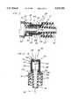
- FIG. 2is a cross-sectional view of the coupling site taken along line 2--2 in FIG. 1, and additionally showing a male luer lock fitting for connection to the coupling site;
- FIG. 3is a view similar to FIG. 2 in which the male luer lock fitting is shown inserted into the coupling site prior to threaded engagement of the male luer lock fitting with the coupling site;
- FIG. 4is a cross-sectional view of the coupling site taken along line 4--4 in FIG. 1;
- FIG. 5is a cross-sectional view taken along line 5--5 in FIG. 2;
- FIG. 6is a perspective view of a second embodiment of the medical coupling device of the present invention.
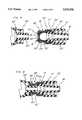
- FIG. 7is a cross-sectional view taken along line 7--7 in FIG. 6, and additionally showing a male luer lock fitting for connection to the coupling site;
- FIG. 8is a cross-sectional view similar to FIG. 7 in which the male luer lock fitting is shown inserted into the coupling site prior to threaded engagement of the male luer lock with the coupling site;
- FIG. 9is a cross-sectional view similar to that shown in FIG. 2 illustrating an alternative configuration for the valve element
- FIG. 10is a cross-sectional view taken along line 10--10 in FIG. 9;
- FIG. 11is a cross-sectional view taken along line 11--11 in FIG. 9;
- FIG. 12is a cross-sectional view similar to that shown in FIG. 2 illustrating a further embodiment of the present invention.
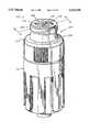
- FIG. 13is a perspective view of a further embodiment of the medical coupling device of the present invention.
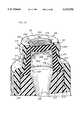
- FIG. 14is a cross-sectional view taken along line 14--14 in FIG. 13;
- FIG. 15is a perspective partially cutaway view of the embodiment of FIG. 13;
- FIG. 16is a partially cutaway bottom perspective view of the valve element used in the embodiment of FIG. 13;
- FIG. 17is a cross-sectional elevational view showing a male luer slip inserted into the coupling site of FIG. 13;
- FIG. 18is an alternative configuration for the valve element of the embodiment of FIG. 13.
- FIG. 19is an enlarged cross-sectional view of an upper portion of the diaphragm in elevation illustrating the profile of the surface texture for the exposed surface of the diaphragm.
- the coupling site 10generally includes a support base 12, a retainer 14 supported on the support base and a valve element 16 located within the retainer.
- the support base 12is formed from a plastic material
- the retainer 14is formed from a metal material such as coated aluminum
- the valve element 16is formed of an elastomeric material such as an elastomer which conforms to standard medical specifications.
- other materialsmay be used for forming the particular elements of the present medical coupling site 10 to the extent that the alternative materials permit the coupling site 10 to function with the advantages to be described below.
- the support base 12preferably includes a tubular luer taper portion 18 defining a longitudinal axis 20 of the coupling site 10.
- the luer taper portion 18is surrounded by a threaded locking collar 22 such that the coupling site 10 may be attached to a standard female luer fitting.
- an outwardly extending flange portion 24is attached to an inner end of the luer taper portion 18 extending from an end wall 26 of the collar 22.
- the valve member 16includes a tubular body portion 28 extending substantially parallel to the longitudinal axis 20 and defining a first end 30 and a second end 32 wherein the second end 32 is in contact with the support base 12 adjacent to the end wall 26.
- the valve element 16further includes a thin flexible diaphragm 34 extending across the first end 30 of the body portion 16.
- the diaphragm 34includes means defining a slit 36 extending diametrically across the diaphragm 34.
- the diaphragm 34defines opposing first and second sides 38, 40 wherein the first side 38 is formed as a concave surface and the second side 40 is formed as a convex surface.
- the concave first surface 38includes a peripheral edge lying in a plane defined by an annular end surface 42 of the body portion 16.
- the first surface 38is provided with a relatively shallow curvature such that the first surface 38 is easily cleaned by wiping of the surface. Also, as a result of forming the diaphragm 34 curved inwardly toward the port base 12, fluid pressure within the site 10 will exert an outwardly directed force on the diaphragm 34 and will tend to cause the material surrounding the slit 36 to compress inwardly, thus biasing the slit closed.
- the second surface 40is shown having a substantially cylindrical curvature, it should be noted that this surface may also be formed having a spherical or dome-shaped curvature.
- the valve element 16is further provided with biasing means which are preferably in the form of first and second ribs 44, 46 extending radially inwardly from an inner wall 48 of the body portion 16 toward the slit 36 in a direction from the second end 32 toward the first end 30.
- the rib members 44, 46are oriented such that they intersect and extend parallel to a plane which intersects the longitudinal axis 20 and extends perpendicular to the slit 36.
- each of the rib members 44, 46define a width dimension in a direction parallel to the slit 36 which is less than an interior diameter defined by the inner wall 48 of the valve body 16.
- the rib members 44, 46have a dimension in a direction parallel to the longitudinal axis 20 which decreases in a direction from the inner wall 48 toward the slit 36.
- the rib members 44, 46reinforce the diaphragm 34 and act to bias the slit 36 to a closed position. Further, by providing rib members 44, 46 which have a width dimension less than the inner diameter of the body portion 16, the space surrounding the rib members 44, 46 is available to accommodate elastomeric material of the diaphragm 34 and body portion 28 as the valve element 16 is distorted during insertion of a male luer taper 50 (see FIG. 2).
- the retainer 14is formed as a tubular sleeve defined by an elongated body 52 having a first end 54 adjacent to the first end 30 of the valve element 16 and a second end 56 adjacent to the second end 32 of the valve element 16.
- the first end 54 of the retainer 14is turned inwardly into the first end of the valve element 16 and is preferably folded over to form a double thickness portion. This portion forms a reduced area for slightly compressing the valve element 16 in the area around the diaphragm 34 to thereby form a seal preventing fluids from passing between the valve element 16 and the retainer 14.
- the second end 56is preferably crimped inwardly toward a gap formed between the flange portion 24 and the end wall 26 to thereby hold the second end 32 of the valve element 16 under the flange portion 24 such that the valve element 16 is firmly held in place on the support base 12.
- the valve body portion 28extends substantially along the length of the retainer 14 and isolates the retainer 14 from fluids flowing through the coupling site, as well as forms a direct fluid path through the site 10 to avoid the formation of crevices or pockets which may retain fluids and hinder flushing of the site between administration of different medicines.
- the inner surface of the elongated body 52preferably defines a diameter which is slightly smaller than the outer diameter of the body portion 28 prior to mounting in the coupling site 10.
- the retainer 14firmly engages the valve element 16 and applies a predetermined compression force for further biasing the material surrounding the slit 36 inwardly toward the axis 20 for closing the slit 36.
- the retainer 14further includes a pair of lugs 58, 60 extending radially outwardly from the outer surface of the retainer body 52.
- the retainer 14is preferably formed from thin material such as coated aluminum, which may be conveniently stamped to a desired shape.
- the lugs 58, 60may be formed as stamped protrusions in the body 52.
- the lugs 58, 60are configured to engage the double helix threads formed on the interior of a threaded locking collar 62 (see FIG. 2) for a standard male luer lock.
- the lugs 58, 60may be formed extending at a slight angle relative to a plane extending perpendicular to the longitudinal axis 20.
- the lugsmay be formed having an alternative configuration, such as a configuration defining threads extending around the entire circumference of the retainer body 52 and that other means of forming the thin metal retainer, such as machining, may be applied.
- the lugs 58, 60are preferably located adjacent to the first end 54 of the retainer 14 and the thickness of the retainer body portion 52 in at least the area adjacent to the lugs has a thickness, as measured in a direction perpendicular to the longitudinal axis 20, which is less than the thickness of the valve element body portion 28.
- the relationship between the thickness of the retainer 14 and the valve element 16is important since only a limited amount of space is available between a standard male luer taper 50 and the surrounded locking collar 62.
- a standard male luer lock 64is illustrated and may be in the form of a standard syringe end including a male luer taper 50 and a threaded locking collar 62.
- the male luer taper 50has an outer diameter of approximately 3.9 mm to 4.0 mm and the threaded locking collar 62 has a minimum inner diameter, as defined by the threaded portion of approximately 7.0 mm to 7.2 mm.
- the male luer taperis formed tapering inwardly at an angle of 6°.
- the retainer 14 of the coupling site 10is formed having a maximum outer diameter for the retainer body 52 of approximately 7.0 mm, and the inner wall 48 of the valve element 16 defines a minimum diameter of 4 mm.
- the configuration of the present coupling site 10results in a site which is particularly adapted to be received between the male luer tip 50 and the locking collar 62 with the outer surface of the site 10 forming a positive mechanical connection with the threads of the collar 62 and with the interior of the valve body 28 providing sufficient clearance for the male luer taper 50 to easily slide into the coupling site 10.
- end surface 65 of the luer taper 18may serve as a convenient stop surface for engaging the end of the luer taper 50 to define a positive lock position between the male luer lock 64 and the coupling site 10.
- the male luer taper 50causes the diaphragm 34 to be stretched and pushed into a distorted position adjacent to the inner wall 48, with an accompanying distortion of the ribs 44, 46.
- the coupling site 10 of the present inventionincorporates a flexible diaphragm member 34 having a slit 36 wherein the slit is biased to a closed position through forces exerted on the diaphragm member by a supporting tubular body portion 28 forming a passage for receiving the male luer taper.
- a diaphragm member 34 for forming the seal on the site endresults in a highly resilient opening offering reduced resistance to forces pushing the male luer taper 50 or other cannula into the coupling site 10 while also providing a reliable closure element when the male luer taper 50 is removed from the site 10.
- the present coupling site 10may also easily be used with a needle in that a needle may be inserted through the diaphragm 34 in the region surrounding the slit 36 if it should be necessary to infuse or withdraw fluids through a needle at the injection site.
- FIGS. 6-8a second embodiment of the present invention is shown and is designated generally as 10'.
- elements in the second embodiment corresponding to elements in the first embodimentare labeled with the same reference numeral primed.
- the embodiment of FIGS. 6-8differs from the previous embodiment in that the area surrounded by the flange portion 24' includes an enlarged passage defining a luer slip 66' which is adapted to receive the end of a standard male luer taper 50'.
- the area of the second end 32' of the body portion 16' and the second end 56' of the retainer 14'are formed with an enlarged diameter, as compared to the previous embodiment, in order to accommodate the enlarged luer slip area 66'.
- the portion of the valve body 28' and the retainer body 52' adjacent to the lugs 58', 60'is formed with the same diameter as in the previous embodiment such that the coupling site 10' will cooperate with a standard male luer lock 64' in the same manner as in the previous embodiment.
- the tip of the luer taper 50'will pass into the luer slip 66' whereby an additional seal is formed between the exterior of the luer taper 50' and the interior of the luer slip 66'.
- the contact between the luer taper 50' and luer slip 66'defines a positive lock position between the luer lock 64' and the coupling site 10'.
- FIGS. 6-8does not affect the advantages afforded by passage of the retainer 14' and valve element 16' in between the luer taper 50' and the locking collar 62' to form a sealed connection wherein the standard luer lock 64' is mechanically locked onto the coupling site 10'.
- FIGS. 9-11show an alternative to the first embodiment in which an alternative valve element 16" is shown and in which the elements for the retainer 14 and the support base 12 remain unchanged and are identified with the same reference numerals as in the first embodiment.
- the valve element 16" of the present embodimentdiffers from the valve element 16 of the first embodiment in that a different rib structure is provided for biasing the slit 36" to a closed position. Specifically, a pair of rib portions 44", 45" and 46", 47” are provided on opposing sides of the slit 36". Each pair of rib members 44", 45" and 46", 47" is separated by a space 68", 70", respectively.
- the rib members 44"-47"operate in the same manner as the ribs 44, 46 of the first embodiment to reinforce the diaphragm 34" and bias the slit 36" to a closed position
- the spaces 68", 70"provide an area for the material of the valve element 16" to deform into when a male luer taper is inserted into the coupling site.
- the rib membersmay be provided in order to bias the valve diaphragm to a closed position.
- the curved surface of the ribs 44, 46 extending from the inner wall 48 of the valve element 16 to the slit 36may be formed as a straight inwardly angled surface or may be provided with some other shape.
- the design of the diaphragm 34 and the reinforcing rib members 44, 46 for biasing the slit to a closed positionmay be altered to provide a predetermined resistance to back flow through the valve element 16.
- the valve element 16may be designed to release fluid from the slit 36 at a predetermined pressure in order to avoid excessive pressure from being applied into a patient at an infusion site.
- the diaphragm 34may be formed as a planar element having opposing first and second sides which are substantially flat. By providing an outwardly facing planar surface, the valve of the present invention would be particularly easy to clean by wiping of the surface.
- FIG. 12shows a further alternative embodiment to the first embodiment in which elements of the further embodiment corresponding to elements in the first embodiment are labeled with the same reference numerals increased by 100.
- the retainer 114is a formed thin element of any relatively rigid material such as metal or plastic.
- the second end 156 of the retainerincludes an enlarged end surface 155 engaging a flange portion 157 of the valve element 116.
- the flange portion 157is located within a groove defined between an inner end of the luer taper portion 118 and a lip 159 extending from the support base 112.
- the lip 159firmly engages the enlarged second end 156 of the retainer 114 in frictional contact to positively maintain the elements of the coupling site 110 in position relative to each other.
- the coupling site 110operates in a manner identical to that of the previous embodiments and differs only in the manner of forming the retainer 114 and in the structure for mounting the retainer 114 and the valve element 116 to the support base 112.
- the retainer of the above-described embodimentsmay also be formed from a plastic material provided the plastic has sufficient rigidity to resist deformation during assembly and use of the coupling site.
- FIGS. 13-19illustrate yet another embodiment of the present invention.
- the medical coupling site 210 of the present embodimentincludes a base 212 supporting a rigid tubular retainer or housing 214, which is preferably formed of a plastic material.
- a rigid tubular retainer or housing 214which is preferably formed of a plastic material.
- an elastomeric valve element 216extends within the housing 214.
- the elastomeric valve element 216includes a tubular body portion 228 and a diaphragm 234 formed integrally with the valve body 228 and extending across a first end 230 of the valve element 216.
- the diaphragm 234includes a substantially planar exposed surface 238 and a convexly curved inner surface 240 which intersects a cylindrical inner wall 248 of the valve body 228 at an acute angle.
- the cylindrical inner wall 248 of the valve body 228defines a luer receiving cavity 213 between the diaphragm 234 and a second end 232 of the valve element 216, and the inner surface 240 of the diaphragm 234 faces toward the luer receiving cavity 213.
- the diaphragm 234includes a slit 236 extending diametrically across and defining an opening through the diaphragm 234.
- a pair of biasing ribs 244, 246extend radially inwardly toward each other from the cylindrical inner wall 248 to the inner surface 240 of the diaphragm 234.
- the rib 244is defined by opposing, substantially planar side walls 245, and the rib 246 is defined by opposing, substantially planar side walls 247.
- the side walls 245, 247extend into the luer receiving cavity 213 substantially perpendicularly from the inner surface 240 of the diaphragm 234.
- Each of the ribs 244, 246further includes a respective facing surface 249, 251 extending substantially perpendicularly from the inner surface 240 of the diaphragm 234.
- the facing surfaces 249, 251are located in alignment with the slit 236 and are in facing relationship for engagement with each other.
- a pair of reinforcing ribs 253are provided at opposing ends of the slit 236 and formed integrally with the diaphragm 234 and inner wall 248.
- the reinforcing ribs 253prevent the diaphragm 234 from tearing at the ends of the slit 236 when a male luer is inserted through the diaphragm 234.
- Each of the biasing ribs 244, 246is formed with a respective hinge point 255, 257.
- the ribs 244, 246are formed with thickened ends adjacent to the inner wall 248 and at the facing surfaces 249, 251, and the hinge points 255, 257 are defined by thin portions of the ribs 244, 246 intermediate the thickened ends.
- the hinge points 255, 257facilitate flexing of the ribs 244, 246 when a male luer 288 (see FIG. 17) is inserted through the diaphragm 234.
- the thickened portions adjacent to the facing surfaces 249, 251facilitate preventing the diaphragm 234 from being pushed open by a fluid pressure from within the luer receiving cavity 213 in that the facing surfaces 249, 251 are adapted to engage each other to prevent outward flexing of the diaphragm 234 at the slit 236.
- valve body 228also includes a substantially cylindrical outer wall portion 259 adjacent to the first end 230 and an outwardly tapered outer wall portion 261 extending from a junction with the cylindrical outer wall portion 259 toward the second end 232 whereby a thickness of the valve body 228 progressively increases in a direction away from the first valve element end 230.
- a flange 278extends radially outwardly from the outwardly tapered outer wall portion 261 at the second end 232.
- the housing 214includes a substantially cylindrical portion 215 adjacent to a first end 254 of the housing 214, and an outwardly tapered portion 217 adjacent to the cylindrical portion 215 and extending toward a second end 256 of the housing 214.
- the cylindrical portion 215includes cylindrical inner and outer walls 219 and 221 wherein the inner wall 219 substantially matches the configuration of the outer wall portion 259 of the valve element 216.
- the outwardly tapered portion 217includes outwardly tapered inner and outer walls 223 and 225 wherein the inner wall 223 substantially corresponds to the configuration of the outer wall portion 261 of the valve element 216.
- a double helix thread 260is formed on the cylindrical outer wall 221 for engaging a threaded locking collar of a standard luer lock.
- the outwardly tapered outer wall 225tapers outwardly to a diameter greater than the interior diameter of a standard luer lock collar such that the luer lock collar may be frictionally locked into engagement with the coupling site 210 as the collar is threaded onto the thread 260.
- the base 212includes an opening 233 sufficiently large to permit free passage of the male luer taper into the base 212.
- the second end 232 of the valve element 216is adapted to rest on a surface 270 of the base 212.
- the thickened portion of the valve element 216 resulting from providing the outwardly tapered outer wall 261provides the valve element 216 with increased column strength to help avoid buckling of the valve body 216 during insertion of a male luer into the luer receiving cavity 213.
- the forces exerted on the valve elementwill be directed radially outwardly against the outwardly tapered portion 217 of the housing 210 to thereby ensure that the valve element 216 maintains its shape and position within the housing 210.
- the housing 210is further provided with a locking flange 229 which extends radially inwardly at the first end 254.
- the flange 229defines a locking edge 231 extending substantially perpendicular relative to the exposed surface 238 of the diaphragm 234.
- the edge 231defines a diameter which is less than a diameter defined by the inner wall 248 of the valve element 216.
- the locking edge 231is adapted to contact a male luer 288 in locking frictional engagement, as seen in FIG. 17.
- the diameter of the locking edge 231is greater than the minimum diameter and less than the maximum diameter of a standard male luer taper 288, as defined by the ANSI and ISO standards, such that the present coupling site may be engaged in locking frictional engagement with a male luer taper 288 which does not have a threaded locking collar, as is illustrated in FIG. 17.
- the flange 229extending over the diaphragm 234 to a location radially inwardly from the radial location of the inner wall 248 of the valve element 216, the flange 229 also provides an additional biasing force on the upper portion of the diaphragm 234 for maintaining the slit 236 closed during high back pressure forces.
- valve element 216 of the present embodimentis illustrated.
- the ribs, identified as 244' and 246'define a slightly different structure and the remainder of the valve element 216 is identical to the configuration previously described wherein identical elements are identified with the same reference numeral.
- the ribs 244' and 246'differ from the previous configuration in that the location of the hinge points 255' and 257' are displaced closer to the inner wall 248 of the valve element 216.
- the different location for the hinge points 255', 257'provides different flexure characteristics for the diaphragm 234. Further, it should be noted that hinge points may be selected at additional points intermediate the locations shown in FIGS. 16 and 18.
- the exposed surface 238 of the diaphragmis provided with a surface texturing which is rougher than that typically found on valve surfaces.
- the exposed surface 238has a controlled roughness in order to facilitate insertion of a male luer taper through the diaphragm 234.
- Prior art valves having a diaphragmwere typically produced having a roughness height value of 16 microinches, measured using the American standard ASA B46.1-1962. However, it has been found that the surface friction produced between a male luer and such a surface is undesirably high.
- the exposed surface 238 of the present inventionis formed having a American standard ASA roughness height value of approximately 180 microinches, and having a multi-directional lay.
- the exposed surface 238is formed with a plurality of minute hills 290 and valleys 292 extending above and below a nominal profile N of the exposed surface 238.
- the exposed surfacemay be provided with a medically acceptable lubricating substance 294, such as a fluid silicone lubricant, which will remain in the valleys 292, below the nominal profile N of the exposed surface 238, during wiping of the surface by a sterile wipe.
- a medically acceptable lubricating substance 294such as a fluid silicone lubricant, which will remain in the valleys 292, below the nominal profile N of the exposed surface 238, during wiping of the surface by a sterile wipe.
- the roughened exposed surface 238facilitates retaining the lubricating substance 294 on the surface 238 during wiping.
- the roughened surfacepermits the lubricant 294 to be retained on the surface to act as a lubricating coating as a male luer engages and distorts the diaphragm 234 during insertion through the slit 236.
- the medical coupling site of the present inventionovercomes the disadvantages associated with prior art sites.
- the present medical coupling siteis provided with a wall structure having a sufficiently thin dimension to pass within the space defined between a standard male luer taper and a locking collar for a standard male luer lock fitting.
- the outer surface of the coupling siteis provided with threads for engaging the double helix threads of the threaded locking collar for a male luer lock whereby the coupling site is held in fixed mechanical engagement with the male luer lock.
- the present inventionalso has an advantage over prior art sites requiring a reduced diameter cannula for insertion through a valve element in that the present invention permits a standard luer taper to be inserted through the valve into the coupling site and the interior diameter of the coupling site is at least as large as the interior diameter of a standard luer taper.
- the coupling site of the present inventiondoes not impose any restrictions to flow resulting from reductions of diameter within the site.
- a further advantage of the present inventionresults from providing biasing means in the form of ribs for controlling the location of the diaphragm and thereby maintaining the slit in a closed position.
- the diaphragm of the present inventiondoes not require excessive forces directed inwardly toward the slit in order to maintain the slit in a closed position, and as a result thereof the ease of insertion of a luer taper into the valve is greatly enhanced.
- a thin rigid retainerin combination with a tubular valve element having a diaphragm extending across an end thereof provides a critical dual function of both providing a mounting structure for the threads and also acting as a reinforcing structure to rigidly support the valve element and thereby ensure closure of the slit, as well as prevent inadvertent opening of the slit resulting from side forces applied to the coupling site at the location of the valve element.
- the medical coupling sitemay be incorporated into existing medical fluid systems without change over of equipment or the use of adapters to incorporate non-standard fittings.
- the present inventionis particularly adapted to be used with standard male luer locks, it may also be used with other cannula or may be accessed with a conventional steel needle.
- the coupling sitefurther provides for a positive feedback of a locked connection such that medical personnel will be able to quickly connect male luer lock fittings to the site.
- valve element diaphragmenables the present coupling site to be used for multiple insertions and with extended indwell times while maintaining its capability to form a fluid-tight seal at the slit upon removal of a luer taper or cannula.
- the design of the coupling site with the valve element extending from a point adjacent to the first end of the sleeve to a point in contact with the support basefurther ensures that crevices for containing pockets of fluid are avoided such that flushing of the valve in between administration of medicines is facilitated.
Landscapes
- Engineering & Computer Science (AREA)
- Health & Medical Sciences (AREA)
- Heart & Thoracic Surgery (AREA)
- General Engineering & Computer Science (AREA)
- Hematology (AREA)
- Pulmonology (AREA)
- Anesthesiology (AREA)
- Biomedical Technology (AREA)
- Mechanical Engineering (AREA)
- Life Sciences & Earth Sciences (AREA)
- Animal Behavior & Ethology (AREA)
- General Health & Medical Sciences (AREA)
- Public Health (AREA)
- Veterinary Medicine (AREA)
- Infusion, Injection, And Reservoir Apparatuses (AREA)
- Quick-Acting Or Multi-Walled Pipe Joints (AREA)
- External Artificial Organs (AREA)
Abstract
Description
Claims (34)
Priority Applications (12)
| Application Number | Priority Date | Filing Date | Title |
|---|---|---|---|
| US08/378,506US5533708A (en) | 1992-06-04 | 1995-01-26 | Medical coupling site valve body |
| CA002207754ACA2207754C (en) | 1995-01-26 | 1996-01-16 | Medical coupling site valve body |
| EP96902692AEP0805930B1 (en) | 1995-01-26 | 1996-01-16 | Medical coupling site valve body |
| DE69636179TDE69636179T2 (en) | 1995-01-26 | 1996-01-16 | Valve housing for medical coupling point |
| DE69637607TDE69637607D1 (en) | 1995-01-26 | 1996-01-16 | Valve housing for medical coupling point |
| EP06111949AEP1669101B1 (en) | 1995-01-26 | 1996-01-16 | Medical coupling site valve body |
| PCT/US1996/000551WO1996023158A1 (en) | 1995-01-26 | 1996-01-16 | Medical coupling site valve body |
| JP52290496AJP3717184B2 (en) | 1995-01-26 | 1996-01-16 | Valve body at medical connection site |
| DE69622018TDE69622018D1 (en) | 1995-01-26 | 1996-01-16 | VALVE HOUSING FOR MEDICAL CLUTCH POINT |
| EP01129448AEP1208872B1 (en) | 1995-01-26 | 1996-01-16 | Medical coupling site valve body |
| AU47002/96AAU687667B2 (en) | 1995-01-26 | 1996-01-16 | Medical coupling site valve body |
| IL11685896AIL116858A0 (en) | 1995-01-26 | 1996-01-22 | Medical coupling site valve body |
Applications Claiming Priority (4)
| Application Number | Priority Date | Filing Date | Title |
|---|---|---|---|
| US07893813US5251873B1 (en) | 1992-06-04 | 1992-06-04 | Medical coupling site. |
| US08/044,830US5295657A (en) | 1992-06-04 | 1993-04-12 | Medical coupling site valve body |
| US15399893A | 1993-11-18 | 1993-11-18 | |
| US08/378,506US5533708A (en) | 1992-06-04 | 1995-01-26 | Medical coupling site valve body |
Related Parent Applications (1)
| Application Number | Title | Priority Date | Filing Date |
|---|---|---|---|
| US15399893AContinuation-In-Part | 1992-06-04 | 1993-11-18 |
Publications (1)
| Publication Number | Publication Date |
|---|---|
| US5533708Atrue US5533708A (en) | 1996-07-09 |
Family
ID=23493380
Family Applications (1)
| Application Number | Title | Priority Date | Filing Date |
|---|---|---|---|
| US08/378,506Expired - LifetimeUS5533708A (en) | 1992-06-04 | 1995-01-26 | Medical coupling site valve body |
Country Status (8)
| Country | Link |
|---|---|
| US (1) | US5533708A (en) |
| EP (3) | EP0805930B1 (en) |
| JP (1) | JP3717184B2 (en) |
| AU (1) | AU687667B2 (en) |
| CA (1) | CA2207754C (en) |
| DE (3) | DE69636179T2 (en) |
| IL (1) | IL116858A0 (en) |
| WO (1) | WO1996023158A1 (en) |
Cited By (153)
| Publication number | Priority date | Publication date | Assignee | Title |
|---|---|---|---|---|
| US5797889A (en)* | 1996-06-19 | 1998-08-25 | Becton Dickinson And Company | Medical device having a connector portion with an improved surface finish |
| WO1999045983A1 (en)* | 1998-03-10 | 1999-09-16 | Vernay Laboratories, Inc. | Hemostasis valve assembly including guide wire seal |
| US5957898A (en) | 1997-05-20 | 1999-09-28 | Baxter International Inc. | Needleless connector |
| WO1999061093A1 (en)* | 1998-05-29 | 1999-12-02 | Lynn Lawrence A | Luer receiver and method for fluid transfer |
| US6024729A (en)* | 1998-03-10 | 2000-02-15 | Vernay Laboratories, Inc. | Hemostasis valve assembly including guide wire seal |
| US6029946A (en)* | 1997-09-15 | 2000-02-29 | Tiva Medical Inc. | Needleless valve |
| US6036171A (en)* | 1997-09-17 | 2000-03-14 | Halkey-Roberts Corporation | Swabbable valve assembly |
| US6089541A (en)* | 1998-09-10 | 2000-07-18 | Halkey-Roberts Corporation | Valve having a valve body and a deformable stem therein |
| US6096011A (en)* | 1998-01-29 | 2000-08-01 | Medrad, Inc. | Aseptic connector and fluid delivery system using such an aseptic connector |
| WO2000059415A1 (en)* | 1999-04-03 | 2000-10-12 | Bieber Biomedical Gmbh | Valve unit, especially for an urological catheter |
| US6206058B1 (en) | 1998-11-09 | 2001-03-27 | The Procter & Gamble Company | Integrated vent and fluid transfer fitment |
| US6228065B1 (en) | 1994-02-15 | 2001-05-08 | Lawrence A. Lynn | Displacement activated medical check valve |
| US6261282B1 (en) | 1997-05-20 | 2001-07-17 | Baxter International Inc. | Needleless connector |
| USRE37357E1 (en) | 1994-05-25 | 2001-09-04 | Lawrence A. Lynn | Luer-receiving medical valve and fluid transfer method |
| US6299132B1 (en) | 1999-03-31 | 2001-10-09 | Halkey-Roberts Corporation | Reflux valve |
| WO2002018005A1 (en)* | 2000-02-16 | 2002-03-07 | Dikeman W Cary | Gastrostomy tube set |
| US20030050610A1 (en)* | 2001-08-22 | 2003-03-13 | Newton Brian L. | Medical valve with expandable member |
| US20030093061A1 (en)* | 2001-11-13 | 2003-05-15 | Ganem Charles F. | Anti-drawback medical valve |
| US6569118B2 (en)* | 2000-05-25 | 2003-05-27 | Johnnie M. Johnson | Adapter and method of attachment for “LUER LOK” receptacles |
| US6585229B2 (en) | 1999-01-27 | 2003-07-01 | Nypro Inc. | Medical nozzle securing apparatus |
| US20030171721A1 (en)* | 2002-03-07 | 2003-09-11 | Nobuo Enomoto | Medical device |
| US6651956B2 (en) | 2002-01-31 | 2003-11-25 | Halkey-Roberts Corporation | Slit-type swabable valve |
| US20040015121A1 (en)* | 2002-05-31 | 2004-01-22 | Baxter International, Inc. | Container having a fluid transfer tube with textured inner surface and method for making the container |
| US20040030321A1 (en)* | 2000-07-11 | 2004-02-12 | Fangrow Thomas F. | Medical valve with positive flow characteristics |
| US20040068239A1 (en)* | 2002-10-04 | 2004-04-08 | Utterberg David S. | Injection site for male luer or other tubular connector |
| US20040068238A1 (en)* | 2002-10-04 | 2004-04-08 | Utterberg David S. | Injection site for male luer or other tubular connector |
| US20040102738A1 (en)* | 2002-11-26 | 2004-05-27 | Medical Ventures, L.L.C. | Pressure actuated flow control valve |
| US6755391B2 (en) | 2000-10-23 | 2004-06-29 | Nypro Inc. | Anti-drawback medical valve |
| US20040133171A1 (en)* | 2002-10-29 | 2004-07-08 | Newton Brian L. | Positive push medical valve with internal seal |
| US6808161B1 (en)* | 1999-09-16 | 2004-10-26 | Terumo Kabushiki Kaisha | Connector |
| US20050038397A1 (en)* | 2003-07-31 | 2005-02-17 | Newton Brian L. | Anti-drawback medical valve |
| US6883778B1 (en) | 1996-11-18 | 2005-04-26 | Nypro Inc. | Apparatus for reducing fluid drawback through a medical valve |
| US20050159710A1 (en)* | 2003-07-03 | 2005-07-21 | Utterberg David S. | Medical device with elastomeric penetrable wall |
| US20050222541A1 (en)* | 1996-12-16 | 2005-10-06 | Lopez George A | Positive flow valve |
| US20050256500A1 (en)* | 2002-08-12 | 2005-11-17 | Jms Co., Ltd. | Needleless port and method of manufacturing the same |
| US6981977B2 (en) | 2001-10-26 | 2006-01-03 | Atrium Medical Corporation | Body fluid cartridge exchange platform device |
| EP1616808A1 (en)* | 1999-04-20 | 2006-01-18 | JMS Co., Ltd. | Liquid communication adapter |
| US20060058773A1 (en)* | 2004-09-15 | 2006-03-16 | John Raybuck | Needle free blood collection device with male connector valve |
| US7033339B1 (en) | 1998-05-29 | 2006-04-25 | Becton Dickinson And Company (Part Interest) | Self sealing luer receiving stopcock |
| US7037303B2 (en) | 2001-07-06 | 2006-05-02 | Opticon Medical, Inc. | Urinary flow control valve |
| US20060118749A1 (en)* | 2004-01-13 | 2006-06-08 | Ryan Dana W | Swabbable needle-free injection port valve system with zero fluid displacement |
| US20060149213A1 (en)* | 2004-12-30 | 2006-07-06 | John Raybuck | Self-sealing male connector device with collapsible body |
| US20060211999A1 (en)* | 2004-11-05 | 2006-09-21 | Fangrow Thomas F | Soft-grip medical connector |
| USRE39334E1 (en) | 1994-05-25 | 2006-10-10 | Lynn Lawrence A | Luer-receiving medical valve and fluid transfer method |
| US20060229571A1 (en)* | 2005-03-24 | 2006-10-12 | Peppel Peter W | Needleless access port valves |
| US20060264841A1 (en)* | 2005-01-14 | 2006-11-23 | Cote Andrew L Sr | Valve with internal lifter |
| US20070088292A1 (en)* | 2005-07-06 | 2007-04-19 | Fangrow Thomas F Jr | Medical connector with closeable male luer |
| US20070093762A1 (en)* | 2005-10-11 | 2007-04-26 | Utterberg David S | Closure for tubular access port |
| US7241285B1 (en) | 2004-12-06 | 2007-07-10 | Medical Ventures, Inc. | Medical site connection |
| US20070225648A1 (en)* | 2006-03-24 | 2007-09-27 | Chris Winsor | Intravenous injection site with split septum and pressure activated flow control valve |
| US20070235674A1 (en)* | 2006-04-11 | 2007-10-11 | Vangsness Todd S | Medical valve with rotating member and method |
| US20070255257A1 (en)* | 2000-12-19 | 2007-11-01 | Kimberly-Clark Worldwide | Sealing Valve Assembly for Medical Products |
| US20070287989A1 (en)* | 2006-05-08 | 2007-12-13 | Becton, Dickinson & Company | Vascular access device pathogenic status indication |
| US20070293822A1 (en)* | 2006-05-08 | 2007-12-20 | Becton, Dickinson & Company | Vascular access device time sensitive status indication |
| US20080009822A1 (en)* | 2003-12-18 | 2008-01-10 | Halkey-Roberts Corporation | Needleless access vial |
| US20080027400A1 (en)* | 2006-07-28 | 2008-01-31 | Becton, Dickinson And Company | Vascular access device non-adhering surfaces |
| US20080027401A1 (en)* | 2006-07-28 | 2008-01-31 | Becton, Dickinson And Company | Vascular access device filtration |
| US20080027410A1 (en)* | 2006-07-28 | 2008-01-31 | Becton, Dickinson And Company | Vascular access device non-adhering membranes |
| US20080027398A1 (en)* | 2006-07-28 | 2008-01-31 | Becton, Dickinson And Company | Vascular access device volume displacement |
| US20080027399A1 (en)* | 2006-07-28 | 2008-01-31 | Becton, Dickinson And Company | Antimicrobial vascular access device |
| US20080033363A1 (en)* | 2004-01-23 | 2008-02-07 | Haberland Gary W | Trocar and cannula assembly having conical valve and related methods |
| US20080039802A1 (en)* | 2006-08-11 | 2008-02-14 | Nypro Inc. | Medical Valve With Expandable Member |
| US20080039803A1 (en)* | 2006-08-09 | 2008-02-14 | Lawrence Allan Lynn | Luer protection pouch™ and luer valve/male luer protection method |
| US20080038167A1 (en)* | 2006-08-09 | 2008-02-14 | Lawrence Allan Lynn | Luer valve disinfectant swab-pouch |
| US20080086097A1 (en)* | 2006-10-05 | 2008-04-10 | Becton, Dickinson And Company | Vascular access device fluid flow direction |
| US20080086099A1 (en)* | 2006-10-05 | 2008-04-10 | Becton, Dickinson And Company | Vascular access device including a tear-resistant septum |
| US20080086100A1 (en)* | 2006-10-05 | 2008-04-10 | Becton, Dickinson And Company | Vascular access device stagnant fluid displacement |
| WO2008043016A2 (en) | 2006-10-05 | 2008-04-10 | Becton, Dickinson And Company | Vascular access devices including a tear-resistant septum |
| US20080108973A1 (en)* | 2006-11-02 | 2008-05-08 | Becton, Dickinson And Company | Vascular access device gas displacement |
| US20080108939A1 (en)* | 2006-11-06 | 2008-05-08 | Becton, Dickinson And Company | Vascular access devices including a tear-resistant septum |
| US20080132832A1 (en)* | 2006-10-11 | 2008-06-05 | Becton, Dickinson And Company | Vascular access device including a tear-resistant septum |
| US20080132833A1 (en)* | 2006-11-06 | 2008-06-05 | Becton, Dickinson And Company | Vascular access devices including a tear-resistant septum |
| US20080132877A1 (en)* | 2006-11-02 | 2008-06-05 | Becton, Dickinson And Company | Vascular access device chamber venting |
| US20080161763A1 (en)* | 2006-07-28 | 2008-07-03 | Becton, Dickinson And Company | Vascular access device antimicrobial materials and solutions |
| US20080172004A1 (en)* | 2006-10-18 | 2008-07-17 | Michael Plishka | Luer activated device with stretchable valve element |
| US20080200904A1 (en)* | 2006-11-06 | 2008-08-21 | Becton, Dickinson And Company | Vascular access device septum venting |
| US20080200903A1 (en)* | 2006-11-06 | 2008-08-21 | Becton, Dickinson And Company | Vascular access device housing venting |
| US20080215004A1 (en)* | 2006-11-02 | 2008-09-04 | Becton, Dickinson And Company | Vascular access device chamber replacement |
| US20080287906A1 (en)* | 2006-11-06 | 2008-11-20 | Becton, Dickinson And Company | Extravascular system venting |
| US20090088663A1 (en)* | 2007-10-01 | 2009-04-02 | Miller Michael E | Surgical system |
| US20090204080A1 (en)* | 2008-02-12 | 2009-08-13 | Baxter International Inc. | Two-way valve connector |
| US7635357B2 (en) | 1994-06-20 | 2009-12-22 | Mayer Bruno Franz P | Needleless injection site |
| US20100030164A1 (en)* | 2008-08-04 | 2010-02-04 | Np Medical Inc. | Medical Valve with Raised Seal |
| US7713250B2 (en) | 2001-12-07 | 2010-05-11 | Becton, Dickinson And Company | Needleless luer access connector |
| US7753892B2 (en) | 2001-11-13 | 2010-07-13 | Nypro Inc. | Anti-drawback medical valve |
| US7753338B2 (en) | 2006-10-23 | 2010-07-13 | Baxter International Inc. | Luer activated device with minimal fluid displacement |
| US7758566B2 (en) | 2003-12-30 | 2010-07-20 | Icu Medical, Inc. | Valve assembly |
| US7789864B2 (en) | 1996-11-18 | 2010-09-07 | Nypro Inc. | Luer-activated valve |
| US20100272148A1 (en)* | 2009-04-23 | 2010-10-28 | Medtronic, Inc. | Multiple Use Temperature Monitor Adapter, System and Method of Using Same |
| US7837658B2 (en) | 2001-11-13 | 2010-11-23 | Nypro Inc. | Anti-drawback medical valve |
| US20100298782A1 (en)* | 2009-05-19 | 2010-11-25 | Nexus Medical, Llc | Intravascular valve component with improved valve positioning |
| US20110009717A1 (en)* | 2009-07-09 | 2011-01-13 | Becton, Dickinson And Company | Blood sampling device |
| US20110082431A1 (en)* | 2009-10-02 | 2011-04-07 | Burgess James E | Connector for Fluid Conduit with Integrated Luer Access Port |
| US7981090B2 (en) | 2006-10-18 | 2011-07-19 | Baxter International Inc. | Luer activated device |
| US7998134B2 (en) | 2007-05-16 | 2011-08-16 | Icu Medical, Inc. | Medical connector |
| USD644731S1 (en) | 2010-03-23 | 2011-09-06 | Icu Medical, Inc. | Medical connector |
| US8105314B2 (en) | 2006-10-25 | 2012-01-31 | Icu Medical, Inc. | Medical connector |
| USD657056S1 (en) | 2009-10-02 | 2012-04-03 | Medline Industries, Inc. | Medical port |
| US20120085958A1 (en)* | 2010-10-08 | 2012-04-12 | Teng-Jen Yang | Plastic formed inflation mouth structure |
| US8221363B2 (en) | 2006-10-18 | 2012-07-17 | Baxter Healthcare S.A. | Luer activated device with valve element under tension |
| US8454563B2 (en) | 2009-10-09 | 2013-06-04 | Rogelio A. Insignares | Trocar and cannula assembly having improved conical valve, and methods related thereto |
| US8454579B2 (en) | 2009-03-25 | 2013-06-04 | Icu Medical, Inc. | Medical connector with automatic valves and volume regulator |
| US20130172768A1 (en)* | 2009-04-29 | 2013-07-04 | Edward Lehman | Intubation-Facilitating Oxygen Mask |
| US8568371B2 (en) | 2009-06-22 | 2013-10-29 | Np Medical Inc. | Medical valve with improved back-pressure sealing |
| US8647310B2 (en) | 2010-05-06 | 2014-02-11 | Icu Medical, Inc. | Medical connector with closeable luer connector |
| US8679090B2 (en) | 2008-12-19 | 2014-03-25 | Icu Medical, Inc. | Medical connector with closeable luer connector |
| US8758306B2 (en) | 2010-05-17 | 2014-06-24 | Icu Medical, Inc. | Medical connectors and methods of use |
| US8808200B2 (en) | 2007-10-01 | 2014-08-19 | Suros Surgical Systems, Inc. | Surgical device and method of using same |
| US9028425B2 (en) | 2010-07-15 | 2015-05-12 | Becton, Dickinson And Company | Vented blood sampling device |
| US9138572B2 (en) | 2010-06-24 | 2015-09-22 | Np Medical Inc. | Medical valve with fluid volume alteration |
| CN104922748A (en)* | 2014-01-08 | 2015-09-23 | B.布劳恩梅尔松根股份公司 | Catheter Assemblies With Valves And Related Methods |
| US9168366B2 (en) | 2008-12-19 | 2015-10-27 | Icu Medical, Inc. | Medical connector with closeable luer connector |
| CN106122634A (en)* | 2016-08-08 | 2016-11-16 | 张誉元 | Self-closing lock quick connector and slip-off preventing Quick insertion connector |
| US9592374B2 (en) | 2010-09-01 | 2017-03-14 | Becton, Dickinson And Company | Catheter adapter having UV-C antimicrobial radiation source and access window within catheter lumen for intravenous therapy |
| USD786427S1 (en) | 2014-12-03 | 2017-05-09 | Icu Medical, Inc. | Fluid manifold |
| USD793551S1 (en) | 2014-12-03 | 2017-08-01 | Icu Medical, Inc. | Fluid manifold |
| US20170224976A1 (en)* | 2016-02-09 | 2017-08-10 | Acist Medical Systems, Inc. | Manifold connection assembly having a surface finish |
| USD794781S1 (en)* | 2015-04-13 | 2017-08-15 | Medela Holding Ag | Valve component for a breastmilk collection system |
| US20170326341A1 (en)* | 2014-12-03 | 2017-11-16 | Tradinco Ab | Self-sealing catheter valve |
| US20180021502A1 (en)* | 2016-07-19 | 2018-01-25 | Industrie Borla S.P.A. | Flow component particularly for haemodialysis medical lines |
| US9925343B2 (en) | 2013-08-07 | 2018-03-27 | Unitract Syringe Pty Ltd | Luer connection adapters for syringes |
| US9931480B2 (en) | 2013-08-07 | 2018-04-03 | Unitract Syringe Pty Ltd | Luer connection adapters for retractable needle syringes |
| US9933094B2 (en) | 2011-09-09 | 2018-04-03 | Icu Medical, Inc. | Medical connectors with fluid-resistant mating interfaces |
| USD831201S1 (en) | 2016-08-29 | 2018-10-16 | Medela Holding Ag | Safety valve component for a breastmilk collection system |
| US10322277B2 (en) | 2010-11-24 | 2019-06-18 | Acist Medical Systems, Inc. | Contrast media injector syringe inlet valve system |
| US10369349B2 (en) | 2013-12-11 | 2019-08-06 | Icu Medical, Inc. | Medical fluid manifold |
| US10376687B2 (en) | 2012-10-16 | 2019-08-13 | Acist Medical Systems, Inc. | Controlling flow in a medical injection system |
| US10695550B2 (en) | 2011-05-20 | 2020-06-30 | Excelsior Medical Corporation | Caps for needleless connectors |
| US10744316B2 (en) | 2016-10-14 | 2020-08-18 | Icu Medical, Inc. | Sanitizing caps for medical connectors |
| US10821278B2 (en) | 2014-05-02 | 2020-11-03 | Excelsior Medical Corporation | Strip package for antiseptic cap |
| US10926078B2 (en) | 2016-12-15 | 2021-02-23 | Industrie Borla S.P.A | Y-connector for medical lines |
| US20210196021A1 (en)* | 2019-12-26 | 2021-07-01 | L'oreal | Valve system for formula cartridge |
| US11071849B2 (en) | 2015-08-18 | 2021-07-27 | B. Braun Melsungen Ag | Catheter devices with valves and related methods |
| US11351353B2 (en) | 2008-10-27 | 2022-06-07 | Icu Medical, Inc. | Packaging container for antimicrobial caps |
| US11384881B2 (en) | 2016-10-20 | 2022-07-12 | Henn Gmbh & Co Kg | Plug-in coupling seal for a fluid line of a drive motor |
| US11389634B2 (en) | 2011-07-12 | 2022-07-19 | Icu Medical, Inc. | Device for delivery of antimicrobial agent into trans-dermal catheter |
| US11400195B2 (en) | 2018-11-07 | 2022-08-02 | Icu Medical, Inc. | Peritoneal dialysis transfer set with antimicrobial properties |
| US11420034B2 (en) | 2017-01-12 | 2022-08-23 | I-V Access Technology, Inc. | Catheter valves |
| US11433215B2 (en) | 2018-11-21 | 2022-09-06 | Icu Medical, Inc. | Antimicrobial device comprising a cap with ring and insert |
| US11517732B2 (en) | 2018-11-07 | 2022-12-06 | Icu Medical, Inc. | Syringe with antimicrobial properties |
| US11517733B2 (en) | 2017-05-01 | 2022-12-06 | Icu Medical, Inc. | Medical fluid connectors and methods for providing additives in medical fluid lines |
| US11534595B2 (en) | 2018-11-07 | 2022-12-27 | Icu Medical, Inc. | Device for delivering an antimicrobial composition into an infusion device |
| US11541221B2 (en) | 2018-11-07 | 2023-01-03 | Icu Medical, Inc. | Tubing set with antimicrobial properties |
| US11541220B2 (en) | 2018-11-07 | 2023-01-03 | Icu Medical, Inc. | Needleless connector with antimicrobial properties |
| US11559467B2 (en) | 2015-05-08 | 2023-01-24 | Icu Medical, Inc. | Medical connectors configured to receive emitters of therapeutic agents |
| US11560964B2 (en) | 2020-08-21 | 2023-01-24 | Acist Medical Systems, Inc. | Valve actuation device coupling |
| US11607525B1 (en)* | 2022-06-30 | 2023-03-21 | I-V Access Technology, Inc. | Methods and devices for vascular access |
| US11701495B2 (en) | 2017-08-31 | 2023-07-18 | I-V Access Technology, Inc. | Methods and devices for vascular access |
| US11850377B2 (en) | 2018-12-17 | 2023-12-26 | B. Braun Melsungen Ag | Catheter assemblies and related methods |
| US20240001079A1 (en)* | 2022-06-30 | 2024-01-04 | I-V Access Technology, Inc. | Methods and devices for vascular access |
| US11944776B2 (en) | 2020-12-07 | 2024-04-02 | Icu Medical, Inc. | Peritoneal dialysis caps, systems and methods |
| US11998716B2 (en) | 2020-01-30 | 2024-06-04 | Acist Medical Systems, Inc. | Valve assembly |
| US12440661B2 (en) | 2022-05-18 | 2025-10-14 | Icu Medical, Inc. | Medical fluid transfer device |
Families Citing this family (21)
| Publication number | Priority date | Publication date | Assignee | Title |
|---|---|---|---|---|
| US20030120214A1 (en) | 2001-03-28 | 2003-06-26 | Howell Glade H. | Blood seal having a spring-biased septum |
| US6228060B1 (en) | 1998-09-02 | 2001-05-08 | Becton, Dickinson And Company | Blood seal having a spring-biased septum |
| EP1218045B1 (en) | 1999-08-12 | 2017-12-13 | Lawrence A. Lynn | Luer receiving vascular access system |
| JP2003305129A (en)* | 2002-04-15 | 2003-10-28 | Koji Karasawa | Lateral injection pipe |
| JP4812236B2 (en)* | 2003-03-27 | 2011-11-09 | 株式会社ジェイ・エム・エス | Medical rubber stopper and medical container |
| US7435236B2 (en)* | 2003-06-27 | 2008-10-14 | Navilyst Medical, Inc. | Pressure actuated valve with improved biasing member |
| JP2005074103A (en)* | 2003-09-02 | 2005-03-24 | Jms Co Ltd | Medical container and medical rubber stopper |
| US9933079B2 (en) | 2004-01-29 | 2018-04-03 | Angiodynamics, Inc. | Stacked membrane for pressure actuated valve |
| US9314608B2 (en) | 2004-01-29 | 2016-04-19 | Angiodynamics, Inc | Pressure activated safety valve with high flow slit |
| JP2007202754A (en)* | 2006-02-01 | 2007-08-16 | Jms Co Ltd | Mixed injection port used for mixed injection |
| JP2008200312A (en)* | 2007-02-21 | 2008-09-04 | Nippon Sherwood Medical Industries Ltd | Liquid infusion tool |
| US8257321B2 (en) | 2008-05-21 | 2012-09-04 | Navilyst Medical, Inc. | Pressure activated valve for high flow rate and pressure venous access applications |
| JP2010167202A (en)* | 2009-01-26 | 2010-08-05 | Jms Co Ltd | Medical port |
| WO2010109449A1 (en) | 2009-03-22 | 2010-09-30 | Elcam Medical Agricultural Cooperative Association Ltd. | Closed male luer connector |
| US8007468B2 (en) | 2009-07-13 | 2011-08-30 | Navilyst Medical, Inc. | Method to secure an elastic component in a valve |
| JP5936859B2 (en)* | 2011-12-26 | 2016-06-22 | 株式会社大協精工 | Two-drug mixing syringe kit |
| US9895524B2 (en) | 2012-07-13 | 2018-02-20 | Angiodynamics, Inc. | Fluid bypass device for valved catheters |
| EP3000502A1 (en)* | 2014-09-29 | 2016-03-30 | Becton Dickinson France | Drug delivery device with coated end-piece |
| US10610678B2 (en) | 2016-08-11 | 2020-04-07 | Angiodynamics, Inc. | Bi-directional, pressure-actuated medical valve with improved fluid flow control and method of using such |
| WO2019073593A1 (en)* | 2017-10-13 | 2019-04-18 | テルモ株式会社 | Barrel for female syringe, syringe kit and syringe connection method |
| JP7389311B2 (en)* | 2019-06-27 | 2023-11-30 | 株式会社トップ | female connector |
Citations (40)
| Publication number | Priority date | Publication date | Assignee | Title |
|---|---|---|---|---|
| US2881937A (en)* | 1954-06-04 | 1959-04-14 | Roberts Charles Buford | Stopper for ampoules and the like |
| US3837381A (en)* | 1972-12-26 | 1974-09-24 | Prod Adex Sa | Shuttoff valve device |
| US4143853A (en)* | 1977-07-14 | 1979-03-13 | Metatech Corporation | Valve for use with a catheter or the like |
| US4387879A (en)* | 1978-04-19 | 1983-06-14 | Eduard Fresenius Chemisch Pharmazeutische Industrie Kg | Self-sealing connector for use with plastic cannulas and vessel catheters |
| US4436519A (en)* | 1981-05-28 | 1984-03-13 | Argon Medical Corp. | Removable hemostasis valve |
| DE3303718C1 (en)* | 1983-02-04 | 1984-10-04 | B. Braun Melsungen Ag, 3508 Melsungen | Injection valve for puncture devices or infusion devices |
| US4511359A (en)* | 1982-09-29 | 1985-04-16 | Manresa, Inc. | Sterile connection device |
| DE8425197U1 (en)* | 1984-08-25 | 1985-09-19 | Magasi, Josef, 6902 Sandhausen | Self-sterile coupling for fluids to be supplied to the human or animal organism, in particular for hyperosmolar peritoneal dialysis fluids |
| US4568336A (en)* | 1984-04-26 | 1986-02-04 | Microbiological Applications, Inc. | Pre-filled hypodermic syringes |
| US4607671A (en)* | 1984-08-21 | 1986-08-26 | Baxter Travenol Laboratories, Inc. | Reconstitution device |
| US4610674A (en)* | 1984-09-13 | 1986-09-09 | Terumo Kabushi Kaisha | Catheter introducing instrument |
| US4629450A (en)* | 1984-05-09 | 1986-12-16 | Terumo Corporation | Catheter introducing instrument |
| EP0223451A2 (en)* | 1985-11-08 | 1987-05-27 | Pharmacia Limited | Improvements in or relating to devices for sampling, drainage or infusion of liquids from or to the human or animal body |
| US4673394A (en)* | 1986-01-17 | 1987-06-16 | Strato Medical Corporation | Implantable treatment reservoir |
| US4673400A (en)* | 1986-02-10 | 1987-06-16 | Martin Ivan W | Aseptic connector assembly for conduits for sterile fluids |
| US4683916A (en)* | 1986-09-25 | 1987-08-04 | Burron Medical Inc. | Normally closed automatic reflux valve |
| WO1988001881A1 (en)* | 1986-09-18 | 1988-03-24 | Aktiebolaget Leo | Connector and a disposable assembly utilizing said connector |
| US4759756A (en)* | 1984-09-14 | 1988-07-26 | Baxter Travenol Laboratories, Inc. | Reconstitution device |
| US4765588A (en)* | 1986-08-18 | 1988-08-23 | Vernay Laboratories, Inc. | Check valve for use with a syringe |
| US4786281A (en)* | 1985-08-02 | 1988-11-22 | Farmitalia Carlo Erba S.P.A. | Device for connecting one end of a liquid medicament delivery cannula to an apparatus for connecting a syringe to a vial containing the medicament |
| DE3809127C1 (en)* | 1988-03-18 | 1989-04-13 | B. Braun Melsungen Ag, 3508 Melsungen, De | |
| EP0314602A2 (en)* | 1987-10-30 | 1989-05-03 | Issei Suzuki | Plug device for a transfusible fluid container |
| US4850975A (en)* | 1987-03-27 | 1989-07-25 | Yuichi Furukawa | Catheter introducer for angiography |
| US4874377A (en)* | 1988-05-26 | 1989-10-17 | Davis Newgard Revocable Family Living Trust | Self-occluding intravascular cannula assembly |
| US4895346A (en)* | 1988-05-02 | 1990-01-23 | The Kendall Company | Valve assembly |
| WO1990011103A2 (en)* | 1989-03-17 | 1990-10-04 | Baxter International Inc. | Pre-slit injection site and tapered cannula |
| DE3913392A1 (en)* | 1989-04-24 | 1990-10-25 | Sterimed Gmbh | CONNECTOR FOR CATHETER |
| US5010925A (en)* | 1990-04-09 | 1991-04-30 | Vernay Laboratories, Inc. | Normally closed duckbill valve assembly |
| US5069424A (en)* | 1990-10-17 | 1991-12-03 | Itt Corporation | Quick connector |
| US5092840A (en)* | 1990-07-16 | 1992-03-03 | Healy Patrick M | Valved medicine container |
| US5100394A (en)* | 1988-01-25 | 1992-03-31 | Baxter International Inc. | Pre-slit injection site |
| WO1992004936A1 (en)* | 1990-09-18 | 1992-04-02 | Medex, Inc. | Needleless connector sample site |
| US5104379A (en)* | 1989-04-03 | 1992-04-14 | Olympus Optical Co., Ltd. | Medical instrument and valve to be mounted on a mount piece of that instrument |
| US5114408A (en)* | 1990-10-18 | 1992-05-19 | Daig Corporation | Universal hemostasis valve having improved sealing characteristics |
| WO1992019293A2 (en)* | 1991-05-02 | 1992-11-12 | Mcgaw, Inc. | Needleless valve |
| US5171234A (en)* | 1988-01-25 | 1992-12-15 | Baxter International, Inc. | Method of effecting a transfer of fluid from a source to a receiver |
| US5190067A (en)* | 1990-05-29 | 1993-03-02 | Nypro, Inc. | Directional flow control |
| US5203775A (en)* | 1990-09-18 | 1993-04-20 | Medex, Inc. | Needleless connector sample site |
| US5251873A (en)* | 1992-06-04 | 1993-10-12 | Vernay Laboratories, Inc. | Medical coupling site |
| US5280876A (en)* | 1993-03-25 | 1994-01-25 | Roger Atkins | Limited restriction quick disconnect valve |
Family Cites Families (2)
| Publication number | Priority date | Publication date | Assignee | Title |
|---|---|---|---|---|
| US5135489A (en)* | 1988-01-25 | 1992-08-04 | Baxter International Inc. | Pre-slit injection site and tapered cannula |
| MX172729B (en)* | 1989-11-09 | 1994-01-10 | Baxter Int | DEVICE FOR CANNULA INSERTION |
- 1995
- 1995-01-26USUS08/378,506patent/US5533708A/ennot_activeExpired - Lifetime
- 1996
- 1996-01-16EPEP96902692Apatent/EP0805930B1/ennot_activeExpired - Lifetime
- 1996-01-16EPEP01129448Apatent/EP1208872B1/ennot_activeExpired - Lifetime
- 1996-01-16DEDE69636179Tpatent/DE69636179T2/ennot_activeExpired - Lifetime
- 1996-01-16WOPCT/US1996/000551patent/WO1996023158A1/enactiveIP Right Grant
- 1996-01-16JPJP52290496Apatent/JP3717184B2/ennot_activeExpired - Fee Related
- 1996-01-16AUAU47002/96Apatent/AU687667B2/ennot_activeCeased
- 1996-01-16EPEP06111949Apatent/EP1669101B1/ennot_activeExpired - Lifetime
- 1996-01-16CACA002207754Apatent/CA2207754C/ennot_activeExpired - Lifetime
- 1996-01-16DEDE69637607Tpatent/DE69637607D1/ennot_activeExpired - Lifetime
- 1996-01-16DEDE69622018Tpatent/DE69622018D1/ennot_activeExpired - Lifetime
- 1996-01-22ILIL11685896Apatent/IL116858A0/enunknown
Patent Citations (42)
| Publication number | Priority date | Publication date | Assignee | Title |
|---|---|---|---|---|
| US2881937A (en)* | 1954-06-04 | 1959-04-14 | Roberts Charles Buford | Stopper for ampoules and the like |
| US3837381A (en)* | 1972-12-26 | 1974-09-24 | Prod Adex Sa | Shuttoff valve device |
| US4143853A (en)* | 1977-07-14 | 1979-03-13 | Metatech Corporation | Valve for use with a catheter or the like |
| US4387879A (en)* | 1978-04-19 | 1983-06-14 | Eduard Fresenius Chemisch Pharmazeutische Industrie Kg | Self-sealing connector for use with plastic cannulas and vessel catheters |
| US4436519B1 (en)* | 1981-05-28 | 1989-04-04 | ||
| US4436519A (en)* | 1981-05-28 | 1984-03-13 | Argon Medical Corp. | Removable hemostasis valve |
| US4511359A (en)* | 1982-09-29 | 1985-04-16 | Manresa, Inc. | Sterile connection device |
| DE3303718C1 (en)* | 1983-02-04 | 1984-10-04 | B. Braun Melsungen Ag, 3508 Melsungen | Injection valve for puncture devices or infusion devices |
| US4568336A (en)* | 1984-04-26 | 1986-02-04 | Microbiological Applications, Inc. | Pre-filled hypodermic syringes |
| US4629450A (en)* | 1984-05-09 | 1986-12-16 | Terumo Corporation | Catheter introducing instrument |
| US4607671A (en)* | 1984-08-21 | 1986-08-26 | Baxter Travenol Laboratories, Inc. | Reconstitution device |
| DE8425197U1 (en)* | 1984-08-25 | 1985-09-19 | Magasi, Josef, 6902 Sandhausen | Self-sterile coupling for fluids to be supplied to the human or animal organism, in particular for hyperosmolar peritoneal dialysis fluids |
| US4610674A (en)* | 1984-09-13 | 1986-09-09 | Terumo Kabushi Kaisha | Catheter introducing instrument |
| US4759756A (en)* | 1984-09-14 | 1988-07-26 | Baxter Travenol Laboratories, Inc. | Reconstitution device |
| US4786281A (en)* | 1985-08-02 | 1988-11-22 | Farmitalia Carlo Erba S.P.A. | Device for connecting one end of a liquid medicament delivery cannula to an apparatus for connecting a syringe to a vial containing the medicament |
| EP0223451A2 (en)* | 1985-11-08 | 1987-05-27 | Pharmacia Limited | Improvements in or relating to devices for sampling, drainage or infusion of liquids from or to the human or animal body |
| US4673394A (en)* | 1986-01-17 | 1987-06-16 | Strato Medical Corporation | Implantable treatment reservoir |
| US4673400A (en)* | 1986-02-10 | 1987-06-16 | Martin Ivan W | Aseptic connector assembly for conduits for sterile fluids |
| US4765588A (en)* | 1986-08-18 | 1988-08-23 | Vernay Laboratories, Inc. | Check valve for use with a syringe |
| WO1988001881A1 (en)* | 1986-09-18 | 1988-03-24 | Aktiebolaget Leo | Connector and a disposable assembly utilizing said connector |
| US4683916A (en)* | 1986-09-25 | 1987-08-04 | Burron Medical Inc. | Normally closed automatic reflux valve |
| US4850975A (en)* | 1987-03-27 | 1989-07-25 | Yuichi Furukawa | Catheter introducer for angiography |
| EP0314602A2 (en)* | 1987-10-30 | 1989-05-03 | Issei Suzuki | Plug device for a transfusible fluid container |
| US5100394A (en)* | 1988-01-25 | 1992-03-31 | Baxter International Inc. | Pre-slit injection site |
| US5171234A (en)* | 1988-01-25 | 1992-12-15 | Baxter International, Inc. | Method of effecting a transfer of fluid from a source to a receiver |
| DE3809127C1 (en)* | 1988-03-18 | 1989-04-13 | B. Braun Melsungen Ag, 3508 Melsungen, De | |
| US4895346A (en)* | 1988-05-02 | 1990-01-23 | The Kendall Company | Valve assembly |
| US4874377A (en)* | 1988-05-26 | 1989-10-17 | Davis Newgard Revocable Family Living Trust | Self-occluding intravascular cannula assembly |
| WO1990011103A2 (en)* | 1989-03-17 | 1990-10-04 | Baxter International Inc. | Pre-slit injection site and tapered cannula |
| US5104379A (en)* | 1989-04-03 | 1992-04-14 | Olympus Optical Co., Ltd. | Medical instrument and valve to be mounted on a mount piece of that instrument |
| DE3913392A1 (en)* | 1989-04-24 | 1990-10-25 | Sterimed Gmbh | CONNECTOR FOR CATHETER |
| US5010925A (en)* | 1990-04-09 | 1991-04-30 | Vernay Laboratories, Inc. | Normally closed duckbill valve assembly |
| US5190067A (en)* | 1990-05-29 | 1993-03-02 | Nypro, Inc. | Directional flow control |
| US5092840A (en)* | 1990-07-16 | 1992-03-03 | Healy Patrick M | Valved medicine container |
| WO1992004936A1 (en)* | 1990-09-18 | 1992-04-02 | Medex, Inc. | Needleless connector sample site |
| US5203775A (en)* | 1990-09-18 | 1993-04-20 | Medex, Inc. | Needleless connector sample site |
| US5069424A (en)* | 1990-10-17 | 1991-12-03 | Itt Corporation | Quick connector |
| US5114408A (en)* | 1990-10-18 | 1992-05-19 | Daig Corporation | Universal hemostasis valve having improved sealing characteristics |
| WO1992019293A2 (en)* | 1991-05-02 | 1992-11-12 | Mcgaw, Inc. | Needleless valve |
| US5251873A (en)* | 1992-06-04 | 1993-10-12 | Vernay Laboratories, Inc. | Medical coupling site |
| US5251873B1 (en)* | 1992-06-04 | 1995-05-02 | Vernay Laboratories | Medical coupling site. |
| US5280876A (en)* | 1993-03-25 | 1994-01-25 | Roger Atkins | Limited restriction quick disconnect valve |
Cited By (378)
| Publication number | Priority date | Publication date | Assignee | Title |
|---|---|---|---|---|
| US6228065B1 (en) | 1994-02-15 | 2001-05-08 | Lawrence A. Lynn | Displacement activated medical check valve |
| US7470261B2 (en) | 1994-04-22 | 2008-12-30 | Lynn Lawrence A | Medical valve |
| USRE39334E1 (en) | 1994-05-25 | 2006-10-10 | Lynn Lawrence A | Luer-receiving medical valve and fluid transfer method |
| USRE37357E1 (en) | 1994-05-25 | 2001-09-04 | Lawrence A. Lynn | Luer-receiving medical valve and fluid transfer method |
| US7635357B2 (en) | 1994-06-20 | 2009-12-22 | Mayer Bruno Franz P | Needleless injection site |
| US5797889A (en)* | 1996-06-19 | 1998-08-25 | Becton Dickinson And Company | Medical device having a connector portion with an improved surface finish |
| US7100890B2 (en) | 1996-11-18 | 2006-09-05 | Nypro Inc. | Swabbable luer-activated valve |
| US7789864B2 (en) | 1996-11-18 | 2010-09-07 | Nypro Inc. | Luer-activated valve |
| US6883778B1 (en) | 1996-11-18 | 2005-04-26 | Nypro Inc. | Apparatus for reducing fluid drawback through a medical valve |
| US20060200089A1 (en)* | 1996-12-16 | 2006-09-07 | Lopez George A | Positive flow valve |
| US20050222541A1 (en)* | 1996-12-16 | 2005-10-06 | Lopez George A | Positive flow valve |
| US20060200088A1 (en)* | 1996-12-16 | 2006-09-07 | Lopez George A | Positive flow valve |
| US6669681B2 (en) | 1997-05-20 | 2003-12-30 | Baxter International Inc. | Needleless connector |
| US5957898A (en) | 1997-05-20 | 1999-09-28 | Baxter International Inc. | Needleless connector |
| USRE43142E1 (en) | 1997-05-20 | 2012-01-24 | Baxter International, Inc. | Needleless connector |
| US6261282B1 (en) | 1997-05-20 | 2001-07-17 | Baxter International Inc. | Needleless connector |
| US6344033B1 (en) | 1997-05-20 | 2002-02-05 | Baxter International, Inc. | Needleless connector |
| US20050121638A1 (en)* | 1997-09-15 | 2005-06-09 | Doyle Mark C. | Needleless valve |
| US6290206B1 (en) | 1997-09-15 | 2001-09-18 | Alaris Medical Systems, Inc. | Needleless valve |
| US6840501B2 (en) | 1997-09-15 | 2005-01-11 | Alaris Medical Systems, Inc. | Needleless valve |
| US6541802B2 (en) | 1997-09-15 | 2003-04-01 | Alaris Medical Systems, Inc. | Needleless valve |
| US20030183795A1 (en)* | 1997-09-15 | 2003-10-02 | Doyle Mark Christopher | Needleless valve |
| US6029946A (en)* | 1997-09-15 | 2000-02-29 | Tiva Medical Inc. | Needleless valve |
| US6036171A (en)* | 1997-09-17 | 2000-03-14 | Halkey-Roberts Corporation | Swabbable valve assembly |
| US6096011A (en)* | 1998-01-29 | 2000-08-01 | Medrad, Inc. | Aseptic connector and fluid delivery system using such an aseptic connector |
| US6440107B1 (en) | 1998-01-29 | 2002-08-27 | Medrad, Inc. | Fluid delivery system and an aseptic connector for use therewith |
| US6024729A (en)* | 1998-03-10 | 2000-02-15 | Vernay Laboratories, Inc. | Hemostasis valve assembly including guide wire seal |
| WO1999045983A1 (en)* | 1998-03-10 | 1999-09-16 | Vernay Laboratories, Inc. | Hemostasis valve assembly including guide wire seal |
| EP1061973A4 (en)* | 1998-03-10 | 2003-01-02 | Vernay Laboratories | Hemostasis valve assembly including guide wire seal |
| WO1999059672A2 (en) | 1998-05-20 | 1999-11-25 | Baxter International Inc. | Needleless connector |
| US8403894B2 (en) | 1998-05-29 | 2013-03-26 | Becton, Dickinson and Company (partial interest) | Luer receiver and method for fluid transfer |
| CN100471535C (en)* | 1998-05-29 | 2009-03-25 | 劳伦斯A·林恩 | Luer receiver and method of infusion |
| US7033339B1 (en) | 1998-05-29 | 2006-04-25 | Becton Dickinson And Company (Part Interest) | Self sealing luer receiving stopcock |
| US20080048144A1 (en)* | 1998-05-29 | 2008-02-28 | Lynn Lawrence A | Luer Receiver and Method for Fluid Transfer |
| US8808254B2 (en) | 1998-05-29 | 2014-08-19 | Becton Dickinson And Company | Luer receiver and method for fluid transfer |
| US6171287B1 (en) | 1998-05-29 | 2001-01-09 | Lawrence A. Lynn | Luer receiver and method for fluid transfer |
| US20080051733A1 (en)* | 1998-05-29 | 2008-02-28 | Lynn Lawrence A | Luer Receiver and Method for Fluid Transfer |
| US20080108956A1 (en)* | 1998-05-29 | 2008-05-08 | Lynn Lawrence A | Luer Receiver and Method for Fluid Transfer |
| US20060129112A1 (en)* | 1998-05-29 | 2006-06-15 | Lynn Lawrence A | Luer receiver and method for fluid transfer |
| US7998122B2 (en) | 1998-05-29 | 2011-08-16 | Becton, Dickinson & Company | Luer receiver and method for fluid transfer |
| US8475416B2 (en) | 1998-05-29 | 2013-07-02 | Lawrence A. Lynn | Luer receiver and method for fluid transfer |
| WO1999061093A1 (en)* | 1998-05-29 | 1999-12-02 | Lynn Lawrence A | Luer receiver and method for fluid transfer |
| US6089541A (en)* | 1998-09-10 | 2000-07-18 | Halkey-Roberts Corporation | Valve having a valve body and a deformable stem therein |
| US6206058B1 (en) | 1998-11-09 | 2001-03-27 | The Procter & Gamble Company | Integrated vent and fluid transfer fitment |
| US6491069B2 (en) | 1998-11-09 | 2002-12-10 | The Procter & Gamble Company | Integrated vent and fluid transfer fitment |
| US20040007287A1 (en)* | 1998-11-09 | 2004-01-15 | The Procter & Gamble Company | Integrated vent and fluid transfer fitment |
| US6612344B2 (en) | 1998-11-09 | 2003-09-02 | The Procter & Gamble Company | Integrated vent and fluid transfer fitment |
| US6427730B2 (en) | 1998-11-09 | 2002-08-06 | The Procter & Gamble Company | Integrated vent and fluid transfer fitment |
| US6585229B2 (en) | 1999-01-27 | 2003-07-01 | Nypro Inc. | Medical nozzle securing apparatus |
| US6299132B1 (en) | 1999-03-31 | 2001-10-09 | Halkey-Roberts Corporation | Reflux valve |
| WO2000059415A1 (en)* | 1999-04-03 | 2000-10-12 | Bieber Biomedical Gmbh | Valve unit, especially for an urological catheter |
| EP1616808A1 (en)* | 1999-04-20 | 2006-01-18 | JMS Co., Ltd. | Liquid communication adapter |
| US6808161B1 (en)* | 1999-09-16 | 2004-10-26 | Terumo Kabushiki Kaisha | Connector |
| WO2002018005A1 (en)* | 2000-02-16 | 2002-03-07 | Dikeman W Cary | Gastrostomy tube set |
| US6419670B1 (en)* | 2000-02-16 | 2002-07-16 | W. Cary Dikeman | Gastrostomy tube set |
| USRE43597E1 (en)* | 2000-05-25 | 2012-08-21 | Mary Lucille Pilkington Trust | Adapter and method of attachment for “LUER LOK” receptacles |
| US6569118B2 (en)* | 2000-05-25 | 2003-05-27 | Johnnie M. Johnson | Adapter and method of attachment for “LUER LOK” receptacles |
| US7628774B2 (en) | 2000-07-11 | 2009-12-08 | Icu Medical, Inc. | Needleless Medical Connector |
| US20060276758A1 (en)* | 2000-07-11 | 2006-12-07 | Fangrow Thomas F Jr | Medical valve with positive flow characteristics |
| US7497849B2 (en) | 2000-07-11 | 2009-03-03 | Icu Medical, Inc. | High flow rate needleless medical connector |
| US8444628B2 (en) | 2000-07-11 | 2013-05-21 | Icu Medical, Inc. | Needleless medical connector |
| US8870850B2 (en) | 2000-07-11 | 2014-10-28 | Icu Medical, Inc. | Medical connector |
| US20040030321A1 (en)* | 2000-07-11 | 2004-02-12 | Fangrow Thomas F. | Medical valve with positive flow characteristics |
| EP2161051A1 (en)* | 2000-07-11 | 2010-03-10 | ICU Medical, Inc. | Needleless medical connector |
| US7763199B2 (en) | 2000-07-11 | 2010-07-27 | Icu Medical, Inc. | Method of making a seal having slit formed therein |
| US6916309B2 (en) | 2000-07-11 | 2005-07-12 | Icu Medical, Inc. | Medical valve with positive flow characteristics |
| US9238129B2 (en) | 2000-07-11 | 2016-01-19 | Icu Medical, Inc. | Medical connector |
| EP1685872A1 (en)* | 2000-07-11 | 2006-08-02 | ICU Medical, Inc. | Medical valve with positive flow characteristics |
| US6695817B1 (en)* | 2000-07-11 | 2004-02-24 | Icu Medical, Inc. | Medical valve with positive flow characteristics |
| US8221391B2 (en) | 2000-07-11 | 2012-07-17 | Icu Medical, Inc. | Needleless medical connector |
| US20060224127A1 (en)* | 2000-07-11 | 2006-10-05 | Fangrow Thomas F Jr | Medical valve with positive flow characteristics |
| US20060264844A1 (en)* | 2000-07-11 | 2006-11-23 | Fangrow Thomas F Jr | Medical valve with positive flow characteristics |
| US20040206924A1 (en)* | 2000-10-23 | 2004-10-21 | Newton Brian L. | Anti-drawback medical valve |
| US6755391B2 (en) | 2000-10-23 | 2004-06-29 | Nypro Inc. | Anti-drawback medical valve |
| US7014169B2 (en) | 2000-10-23 | 2006-03-21 | Nypro Inc. | Anti-drawback medical valve |
| US8579870B2 (en)* | 2000-12-19 | 2013-11-12 | Kimberly-Clark Worldwide, Inc. | Sealing valve assembly for medical products |
| US20070255257A1 (en)* | 2000-12-19 | 2007-11-01 | Kimberly-Clark Worldwide | Sealing Valve Assembly for Medical Products |
| US7037303B2 (en) | 2001-07-06 | 2006-05-02 | Opticon Medical, Inc. | Urinary flow control valve |
| US7396348B2 (en) | 2001-08-22 | 2008-07-08 | Nypro Inc. | Medical valve with expandable member |
| US20030050610A1 (en)* | 2001-08-22 | 2003-03-13 | Newton Brian L. | Medical valve with expandable member |
| US6981977B2 (en) | 2001-10-26 | 2006-01-03 | Atrium Medical Corporation | Body fluid cartridge exchange platform device |
| US6869426B2 (en) | 2001-11-13 | 2005-03-22 | Nypro Inc. | Anti-drawback medical valve |
| US8876784B2 (en) | 2001-11-13 | 2014-11-04 | Np Medical Inc. | Anti-drawback medical valve |
| US7753892B2 (en) | 2001-11-13 | 2010-07-13 | Nypro Inc. | Anti-drawback medical valve |
| US20030093061A1 (en)* | 2001-11-13 | 2003-05-15 | Ganem Charles F. | Anti-drawback medical valve |
| US7837658B2 (en) | 2001-11-13 | 2010-11-23 | Nypro Inc. | Anti-drawback medical valve |
| US7713250B2 (en) | 2001-12-07 | 2010-05-11 | Becton, Dickinson And Company | Needleless luer access connector |
| US7947032B2 (en) | 2001-12-07 | 2011-05-24 | Becton, Dickinson And Company | Needleless luer access connector |
| US6651956B2 (en) | 2002-01-31 | 2003-11-25 | Halkey-Roberts Corporation | Slit-type swabable valve |
| US20030171721A1 (en)* | 2002-03-07 | 2003-09-11 | Nobuo Enomoto | Medical device |
| US20040015121A1 (en)* | 2002-05-31 | 2004-01-22 | Baxter International, Inc. | Container having a fluid transfer tube with textured inner surface and method for making the container |
| US7306579B2 (en)* | 2002-08-12 | 2007-12-11 | Jms Co., Ltd. | Needleless port |
| US20050256500A1 (en)* | 2002-08-12 | 2005-11-17 | Jms Co., Ltd. | Needleless port and method of manufacturing the same |
| CN100460030C (en)* | 2002-08-12 | 2009-02-11 | 株式会社Jms | Needle-less port and method of producing the same |
| US7056308B2 (en) | 2002-10-04 | 2006-06-06 | Dsu Medical Corporation | Medical device with elastomeric penetrable wall and inner seal |
| US7025744B2 (en) | 2002-10-04 | 2006-04-11 | Dsu Medical Corporation | Injection site for male luer or other tubular connector |
| US20040068239A1 (en)* | 2002-10-04 | 2004-04-08 | Utterberg David S. | Injection site for male luer or other tubular connector |
| US20040068238A1 (en)* | 2002-10-04 | 2004-04-08 | Utterberg David S. | Injection site for male luer or other tubular connector |
| US8647312B2 (en) | 2002-10-04 | 2014-02-11 | Nxstage Medical, Inc. | Injection site for male luer or other tubular connector |
| US8377039B2 (en) | 2002-10-04 | 2013-02-19 | Nxstage Medical, Inc. | Injection site for male luer or other tubular connector |
| US7357792B2 (en) | 2002-10-29 | 2008-04-15 | Nypro Inc. | Positive push medical valve with internal seal |
| US20040133171A1 (en)* | 2002-10-29 | 2004-07-08 | Newton Brian L. | Positive push medical valve with internal seal |
| US20090264832A1 (en)* | 2002-11-26 | 2009-10-22 | Nexus Medical, Llc | Pressure actuated flow control valve |
| US7959614B2 (en) | 2002-11-26 | 2011-06-14 | Nexus Medical, Llc | Pressure actuated flow control valve |
| US20100036328A1 (en)* | 2002-11-26 | 2010-02-11 | Nexus Medical, Llc | Pressure actuated flow control valve |
| US20040102738A1 (en)* | 2002-11-26 | 2004-05-27 | Medical Ventures, L.L.C. | Pressure actuated flow control valve |
| US20050010176A1 (en)* | 2002-11-26 | 2005-01-13 | Dikeman W. Cary | Pressure actuated flow control valve |
| US7601141B2 (en) | 2002-11-26 | 2009-10-13 | Nexus Medical, Llc | Pressure actuated flow control valve |
| US20130012870A1 (en)* | 2002-11-26 | 2013-01-10 | Nexus Medical, Llc | Pressure actuated flow control valve |
| US8328769B2 (en)* | 2002-11-26 | 2012-12-11 | Nexus Medical, Llc | Pressure actuated flow control valve |
| US8882742B2 (en)* | 2002-11-26 | 2014-11-11 | Nexus Medical, Llc | Pressure actuated flow control valve |
| US8057442B2 (en)* | 2002-11-26 | 2011-11-15 | Nexus Medical, Llc | Pressure actuated flow control valve |
| US20120059312A1 (en)* | 2002-11-26 | 2012-03-08 | Nexus Medical, Llc | Pressure actuated flow control valve |
| US7569047B2 (en) | 2003-07-03 | 2009-08-04 | Dsu Medical Corporation | Medical device with elastomeric penetrable wall |
| US20050159710A1 (en)* | 2003-07-03 | 2005-07-21 | Utterberg David S. | Medical device with elastomeric penetrable wall |
| US7914502B2 (en) | 2003-07-31 | 2011-03-29 | Nypro Inc. | Anti-drawback medical valve |
| US9604047B2 (en) | 2003-07-31 | 2017-03-28 | Np Medical Inc. | Anti-drawback medical valve |
| US20050038397A1 (en)* | 2003-07-31 | 2005-02-17 | Newton Brian L. | Anti-drawback medical valve |
| US20080009822A1 (en)* | 2003-12-18 | 2008-01-10 | Halkey-Roberts Corporation | Needleless access vial |
| US9592344B2 (en) | 2003-12-30 | 2017-03-14 | Icu Medical, Inc. | Medical connector with internal valve member movable within male luer projection |
| US11266785B2 (en) | 2003-12-30 | 2022-03-08 | Icu Medical, Inc. | Medical connector with internal valve member movable within male projection |
| US8556868B2 (en) | 2003-12-30 | 2013-10-15 | Icu Medical, Inc. | Syringe with multi-pronged actuator |
| US7758566B2 (en) | 2003-12-30 | 2010-07-20 | Icu Medical, Inc. | Valve assembly |
| US9913945B2 (en) | 2003-12-30 | 2018-03-13 | Icu Medical, Inc. | Medical connector with internal valve member movable within male luer projection |
| US9707346B2 (en) | 2003-12-30 | 2017-07-18 | Icu Medical, Inc. | Medical valve connector |
| US10105492B2 (en) | 2003-12-30 | 2018-10-23 | Icu Medical, Inc. | Medical connector with internal valve member movable within male luer projection |
| US8066692B2 (en) | 2003-12-30 | 2011-11-29 | Icu Medical, Inc. | Medical male luer connector with increased closing volume |
| US20060118749A1 (en)* | 2004-01-13 | 2006-06-08 | Ryan Dana W | Swabbable needle-free injection port valve system with zero fluid displacement |
| US8096525B2 (en) | 2004-01-13 | 2012-01-17 | Rymed Technologies, Inc. | Swabbable needle-free injection port valve system with zero fluid displacement |
| US7530546B2 (en)* | 2004-01-13 | 2009-05-12 | Rymed Technologies, Inc. | Swabbable needle-free injection port valve system with zero fluid displacement |
| US20090200504A1 (en)* | 2004-01-13 | 2009-08-13 | Ryan Dana Wm | Swabbable needle-free injection port valve system with zero fluid displacement |
| US20080033363A1 (en)* | 2004-01-23 | 2008-02-07 | Haberland Gary W | Trocar and cannula assembly having conical valve and related methods |
| US7842013B2 (en) | 2004-01-23 | 2010-11-30 | Genico, Inc. | Trocar and cannula assembly having conical valve and related methods |
| US7306566B2 (en) | 2004-09-15 | 2007-12-11 | Cardinal Health 303, Inc. | Needle free blood collection device with male connector valve |
| US20060058773A1 (en)* | 2004-09-15 | 2006-03-16 | John Raybuck | Needle free blood collection device with male connector valve |
| US20060270999A1 (en)* | 2004-11-05 | 2006-11-30 | Fangrow Thomas F | Soft-grip medical connector |
| US20070112313A1 (en)* | 2004-11-05 | 2007-05-17 | Fangrow Thomas F | Soft-grip medical connector |
| US9415200B2 (en) | 2004-11-05 | 2016-08-16 | Icu Medical, Inc. | Medical connector |
| US20060264910A1 (en)* | 2004-11-05 | 2006-11-23 | Fangrow Thomas F | Soft-grip medical connector |
| US7824393B2 (en) | 2004-11-05 | 2010-11-02 | Icu Medical, Inc. | Medical connector having high flow rate characteristics |
| US20060211999A1 (en)* | 2004-11-05 | 2006-09-21 | Fangrow Thomas F | Soft-grip medical connector |
| US20060271016A1 (en)* | 2004-11-05 | 2006-11-30 | Fangrow Thomas F | Soft-grip medical connector |
| US9884176B2 (en) | 2004-11-05 | 2018-02-06 | Icu Medical, Inc. | Medical connector |
| US11883623B2 (en) | 2004-11-05 | 2024-01-30 | Icu Medical, Inc. | Medical connector |
| US10722698B2 (en) | 2004-11-05 | 2020-07-28 | Icu Medical, Inc. | Medical connector |
| US9186494B2 (en) | 2004-11-05 | 2015-11-17 | Icu Medical, Inc. | Medical connector |
| US7241285B1 (en) | 2004-12-06 | 2007-07-10 | Medical Ventures, Inc. | Medical site connection |
| US20060149213A1 (en)* | 2004-12-30 | 2006-07-06 | John Raybuck | Self-sealing male connector device with collapsible body |
| US7651481B2 (en) | 2004-12-30 | 2010-01-26 | CareFusion 303 Inc. | Self-sealing male connector device with collapsible body |
| US20060264841A1 (en)* | 2005-01-14 | 2006-11-23 | Cote Andrew L Sr | Valve with internal lifter |
| US7887519B2 (en) | 2005-01-14 | 2011-02-15 | Nypro Inc. | Valve with internal lifter |
| US20060229571A1 (en)* | 2005-03-24 | 2006-10-12 | Peppel Peter W | Needleless access port valves |
| US7615035B2 (en)* | 2005-03-24 | 2009-11-10 | B. Braun Medical Inc. | Needleless access port valves |
| US7815614B2 (en) | 2005-07-06 | 2010-10-19 | Icu Medical, Inc. | Medical connector with closeable male luer |
| US9126028B2 (en) | 2005-07-06 | 2015-09-08 | Icu Medical, Inc. | Medical connector |
| US7803139B2 (en) | 2005-07-06 | 2010-09-28 | Icu Medical, Inc. | Medical connector with closeable male luer |
| US9358379B2 (en) | 2005-07-06 | 2016-06-07 | Icu Medical, Inc. | Medical connector with closeable male luer |
| US9974940B2 (en) | 2005-07-06 | 2018-05-22 | Icu Medical, Inc. | Medical connector |
| US9974939B2 (en) | 2005-07-06 | 2018-05-22 | Icu Medical, Inc. | Medical connector |
| US9724504B2 (en) | 2005-07-06 | 2017-08-08 | Icu Medical, Inc. | Medical connector |
| US8777908B2 (en)* | 2005-07-06 | 2014-07-15 | Icu Medical, Inc. | Medical connector with closeable male luer |
| US8211069B2 (en)* | 2005-07-06 | 2012-07-03 | Icu Medical, Inc. | Medical connector with closeable male luer |
| US8777909B2 (en)* | 2005-07-06 | 2014-07-15 | Icu Medical, Inc. | Medical connector with closeable male luer |
| US10842982B2 (en) | 2005-07-06 | 2020-11-24 | Icu Medical, Inc. | Medical connector |
| US8262628B2 (en)* | 2005-07-06 | 2012-09-11 | Icu Medical, Inc. | Medical connector with closeable male luer |
| US9114242B2 (en) | 2005-07-06 | 2015-08-25 | Icu Medical, Inc. | Medical connector |
| US9636492B2 (en) | 2005-07-06 | 2017-05-02 | Icu Medical, Inc. | Medical connector with translating rigid internal valve member and narrowed passage |
| US9126029B2 (en) | 2005-07-06 | 2015-09-08 | Icu Medical, Inc. | Medical connector |
| US7803140B2 (en) | 2005-07-06 | 2010-09-28 | Icu Medical, Inc. | Medical connector with closeable male luer |
| US20070088292A1 (en)* | 2005-07-06 | 2007-04-19 | Fangrow Thomas F Jr | Medical connector with closeable male luer |
| US8641684B2 (en) | 2005-10-11 | 2014-02-04 | Nxstage Medical, Inc. | Closure for tubular access port |
| US20070093762A1 (en)* | 2005-10-11 | 2007-04-26 | Utterberg David S | Closure for tubular access port |
| WO2007087500A3 (en)* | 2006-01-26 | 2008-06-26 | Rymed Technologies Inc | Injection pot valve with neutral fluid displacement |
| US8211089B2 (en) | 2006-03-24 | 2012-07-03 | Nexus Medical, Llc | Intravenous injection site with split septum and pressure activated flow control valve |
| US20070225648A1 (en)* | 2006-03-24 | 2007-09-27 | Chris Winsor | Intravenous injection site with split septum and pressure activated flow control valve |
| US7857284B2 (en) | 2006-04-11 | 2010-12-28 | Nypro Inc. | Medical valve with movable member |
| US20070238337A1 (en)* | 2006-04-11 | 2007-10-11 | Ian Kimball | Medical valve with resilient biasing member |
| US20070235675A1 (en)* | 2006-04-11 | 2007-10-11 | Ian Kimball | Medical valve with movable member |
| US20070235674A1 (en)* | 2006-04-11 | 2007-10-11 | Vangsness Todd S | Medical valve with rotating member and method |
| US8968261B2 (en) | 2006-04-11 | 2015-03-03 | Np Medical Inc. | Medical valve with resilient biasing member |
| US8002755B2 (en) | 2006-04-11 | 2011-08-23 | Nypro Inc. | Anti-drawback medical valve and method |
| US7815168B2 (en) | 2006-04-11 | 2010-10-19 | Nypro Inc. | Medical valve with rotating member and method |
| US7879012B2 (en) | 2006-04-11 | 2011-02-01 | Nypro Inc. | Medical valve with resilient sealing member |
| US20110130726A1 (en)* | 2006-05-08 | 2011-06-02 | Becton, Dickinson And Company | Vascular access device time sensitive status indication |
| US8137303B2 (en) | 2006-05-08 | 2012-03-20 | Becton, Dickinson And Company | Vascular access device cleaning status indication |
| US8540944B2 (en) | 2006-05-08 | 2013-09-24 | Becton, Dickinson And Company | Vascular access device time sensitive status indication |
| US20070287989A1 (en)* | 2006-05-08 | 2007-12-13 | Becton, Dickinson & Company | Vascular access device pathogenic status indication |
| US8257663B2 (en) | 2006-05-08 | 2012-09-04 | Becton, Dickinson And Company | Vascular access device time sensitive status indication |
| US20110130728A1 (en)* | 2006-05-08 | 2011-06-02 | Becton, Dickinson And Company | Vascular access device time sensitive status indication |
| US20110130727A1 (en)* | 2006-05-08 | 2011-06-02 | Becton, Dickinson And Company | Vascular access device time sensitive status indication |
| US20070293818A1 (en)* | 2006-05-08 | 2007-12-20 | Becton, Dickinson & Company | Vascular access device cleaning status indication |
| US8715248B2 (en) | 2006-05-08 | 2014-05-06 | Becton, Dickinson And Company | Vascular access device time sensitive status indication |
| US8163237B2 (en) | 2006-05-08 | 2012-04-24 | Becton, Dickinson And Company | Vascular access device pathogenic status indication |
| US20070293822A1 (en)* | 2006-05-08 | 2007-12-20 | Becton, Dickinson & Company | Vascular access device time sensitive status indication |
| US7785299B2 (en) | 2006-05-08 | 2010-08-31 | Becton, Dickinson And Company | Vascular access device time sensitive status indication |
| US8512294B2 (en) | 2006-07-28 | 2013-08-20 | Becton, Dickinson And Company | Vascular access device antimicrobial materials and solutions |
| US20080027399A1 (en)* | 2006-07-28 | 2008-01-31 | Becton, Dickinson And Company | Antimicrobial vascular access device |
| US20080027410A1 (en)* | 2006-07-28 | 2008-01-31 | Becton, Dickinson And Company | Vascular access device non-adhering membranes |
| US20080027400A1 (en)* | 2006-07-28 | 2008-01-31 | Becton, Dickinson And Company | Vascular access device non-adhering surfaces |
| US20080027398A1 (en)* | 2006-07-28 | 2008-01-31 | Becton, Dickinson And Company | Vascular access device volume displacement |
| US8197452B2 (en) | 2006-07-28 | 2012-06-12 | Becton, Dickinson And Company | Vascular access device non-adhering surfaces |
| US7806890B2 (en) | 2006-07-28 | 2010-10-05 | Mckinnon Austin Jason | Vascular access device volume displacement |
| US20080027401A1 (en)* | 2006-07-28 | 2008-01-31 | Becton, Dickinson And Company | Vascular access device filtration |
| US20080161763A1 (en)* | 2006-07-28 | 2008-07-03 | Becton, Dickinson And Company | Vascular access device antimicrobial materials and solutions |
| US20080039803A1 (en)* | 2006-08-09 | 2008-02-14 | Lawrence Allan Lynn | Luer protection pouch™ and luer valve/male luer protection method |
| US20080038167A1 (en)* | 2006-08-09 | 2008-02-14 | Lawrence Allan Lynn | Luer valve disinfectant swab-pouch |
| US8480968B2 (en)* | 2006-08-09 | 2013-07-09 | Lawrence Allan Lynn | Luer valve disinfectant swab-pouch |
| US20080039802A1 (en)* | 2006-08-11 | 2008-02-14 | Nypro Inc. | Medical Valve With Expandable Member |
| US8100869B2 (en) | 2006-08-11 | 2012-01-24 | Nypro Inc. | Medical valve with expandable member |
| US20080086097A1 (en)* | 2006-10-05 | 2008-04-10 | Becton, Dickinson And Company | Vascular access device fluid flow direction |
| US20080086100A1 (en)* | 2006-10-05 | 2008-04-10 | Becton, Dickinson And Company | Vascular access device stagnant fluid displacement |
| WO2008043016A2 (en) | 2006-10-05 | 2008-04-10 | Becton, Dickinson And Company | Vascular access devices including a tear-resistant septum |
| US20080086099A1 (en)* | 2006-10-05 | 2008-04-10 | Becton, Dickinson And Company | Vascular access device including a tear-resistant septum |
| US8062267B2 (en) | 2006-10-05 | 2011-11-22 | Becton, Dickinson And Company | Vascular access device including a tear-resistant septum |
| EP2081631A4 (en)* | 2006-10-05 | 2010-11-03 | Becton Dickinson Co | Vascular access devices including a tear-resistant septum |
| US20090088729A1 (en)* | 2006-10-05 | 2009-04-02 | Becton, Dickinson And Company | Vascular Access Devices Including A Tear-Resistant Septum |
| US7722563B2 (en) | 2006-10-05 | 2010-05-25 | Becton, Dickinson And Company | Vascular access device stagnant fluid displacement |
| US8062266B2 (en) | 2006-10-11 | 2011-11-22 | Becton, Dickinson And Company | Vascular access device including a tear-resistant septum |
| US20080132832A1 (en)* | 2006-10-11 | 2008-06-05 | Becton, Dickinson And Company | Vascular access device including a tear-resistant septum |
| US7981090B2 (en) | 2006-10-18 | 2011-07-19 | Baxter International Inc. | Luer activated device |
| US8221363B2 (en) | 2006-10-18 | 2012-07-17 | Baxter Healthcare S.A. | Luer activated device with valve element under tension |
| US20080172004A1 (en)* | 2006-10-18 | 2008-07-17 | Michael Plishka | Luer activated device with stretchable valve element |
| US7753338B2 (en) | 2006-10-23 | 2010-07-13 | Baxter International Inc. | Luer activated device with minimal fluid displacement |
| US8398607B2 (en) | 2006-10-25 | 2013-03-19 | Icu Medical, Inc. | Medical connector |
| US8105314B2 (en) | 2006-10-25 | 2012-01-31 | Icu Medical, Inc. | Medical connector |
| US8628515B2 (en) | 2006-10-25 | 2014-01-14 | Icu Medical, Inc. | Medical connector |
| US9533137B2 (en) | 2006-10-25 | 2017-01-03 | Icu Medical, Inc. | Medical connector |
| US8366676B2 (en) | 2006-11-02 | 2013-02-05 | Becton, Dickinson And Company | Vascular access device gas displacement |
| US8337483B2 (en) | 2006-11-02 | 2012-12-25 | Becton, Dickinson And Company | Vascular access device chamber replacement |
| US8540677B2 (en) | 2006-11-02 | 2013-09-24 | Becton, Dickinson And Company | Vascular access device chamber venting |
| US20080108973A1 (en)* | 2006-11-02 | 2008-05-08 | Becton, Dickinson And Company | Vascular access device gas displacement |
| US20080132877A1 (en)* | 2006-11-02 | 2008-06-05 | Becton, Dickinson And Company | Vascular access device chamber venting |
| US20080215004A1 (en)* | 2006-11-02 | 2008-09-04 | Becton, Dickinson And Company | Vascular access device chamber replacement |
| US8066670B2 (en) | 2006-11-06 | 2011-11-29 | Becton, Dickinson And Company | Vascular access device septum venting |
| US8066669B2 (en) | 2006-11-06 | 2011-11-29 | Becton, Dickinson And Company | Vascular access device housing venting |
| US20080108939A1 (en)* | 2006-11-06 | 2008-05-08 | Becton, Dickinson And Company | Vascular access devices including a tear-resistant septum |
| US20080200904A1 (en)* | 2006-11-06 | 2008-08-21 | Becton, Dickinson And Company | Vascular access device septum venting |
| US20080200903A1 (en)* | 2006-11-06 | 2008-08-21 | Becton, Dickinson And Company | Vascular access device housing venting |
| US8074338B2 (en) | 2006-11-06 | 2011-12-13 | Becton, Dickinson And Company | Vascular access devices including a tear-resistant septum |
| US20080132833A1 (en)* | 2006-11-06 | 2008-06-05 | Becton, Dickinson And Company | Vascular access devices including a tear-resistant septum |
| US20080287906A1 (en)* | 2006-11-06 | 2008-11-20 | Becton, Dickinson And Company | Extravascular system venting |
| US8377040B2 (en) | 2006-11-06 | 2013-02-19 | Becton, Dickinson And Company | Extravascular system venting |
| US10398887B2 (en) | 2007-05-16 | 2019-09-03 | Icu Medical, Inc. | Medical connector |
| US7998134B2 (en) | 2007-05-16 | 2011-08-16 | Icu Medical, Inc. | Medical connector |
| US11786715B2 (en) | 2007-05-16 | 2023-10-17 | Icu Medical, Inc. | Medical connector |
| US20090088664A1 (en)* | 2007-10-01 | 2009-04-02 | Miller Michael E | Surgical device and method for using same |
| US20090088663A1 (en)* | 2007-10-01 | 2009-04-02 | Miller Michael E | Surgical system |
| US8808200B2 (en) | 2007-10-01 | 2014-08-19 | Suros Surgical Systems, Inc. | Surgical device and method of using same |
| US8187204B2 (en) | 2007-10-01 | 2012-05-29 | Suros Surgical Systems, Inc. | Surgical device and method for using same |
| US8202229B2 (en) | 2007-10-01 | 2012-06-19 | Suros Surgical Systems, Inc. | Surgical device |
| US20090204080A1 (en)* | 2008-02-12 | 2009-08-13 | Baxter International Inc. | Two-way valve connector |
| US20100030164A1 (en)* | 2008-08-04 | 2010-02-04 | Np Medical Inc. | Medical Valve with Raised Seal |
| US11351353B2 (en) | 2008-10-27 | 2022-06-07 | Icu Medical, Inc. | Packaging container for antimicrobial caps |
| US11478624B2 (en) | 2008-12-19 | 2022-10-25 | Icu Medical, Inc. | Medical connector with closeable luer connector |
| US10046154B2 (en) | 2008-12-19 | 2018-08-14 | Icu Medical, Inc. | Medical connector with closeable luer connector |
| US12280230B2 (en) | 2008-12-19 | 2025-04-22 | Icu Medical, Inc. | Medical connector with closeable luer connector |
| US9168366B2 (en) | 2008-12-19 | 2015-10-27 | Icu Medical, Inc. | Medical connector with closeable luer connector |
| US10716928B2 (en) | 2008-12-19 | 2020-07-21 | Icu Medical, Inc. | Medical connector with closeable luer connector |
| US8679090B2 (en) | 2008-12-19 | 2014-03-25 | Icu Medical, Inc. | Medical connector with closeable luer connector |
| US11376411B2 (en) | 2009-03-25 | 2022-07-05 | Icu Medical, Inc. | Medical connectors and methods of use |
| US11931539B2 (en) | 2009-03-25 | 2024-03-19 | Icu Medical, Inc. | Medical connectors and methods of use |
| US11896795B2 (en) | 2009-03-25 | 2024-02-13 | Icu Medical, Inc | Medical connector having elongated portion within closely conforming seal collar |
| US10086188B2 (en) | 2009-03-25 | 2018-10-02 | Icu Medical, Inc. | Medical connectors and methods of use |
| US9278206B2 (en) | 2009-03-25 | 2016-03-08 | Icu Medical, Inc. | Medical connectors and methods of use |
| US10391293B2 (en) | 2009-03-25 | 2019-08-27 | Icu Medical, Inc. | Medical connectors and methods of use |
| US11986618B1 (en) | 2009-03-25 | 2024-05-21 | Icu Medical, Inc. | Medical connector having elongated portion within seal collar |
| US9440060B2 (en) | 2009-03-25 | 2016-09-13 | Icu Medical, Inc. | Medical connectors and methods of use |
| US12285584B2 (en) | 2009-03-25 | 2025-04-29 | Icu Medical, Inc. | Medical connector with elongated portion within seal collar |
| US8454579B2 (en) | 2009-03-25 | 2013-06-04 | Icu Medical, Inc. | Medical connector with automatic valves and volume regulator |
| US12059545B2 (en) | 2009-03-25 | 2024-08-13 | Icu Medical, Inc. | Medical connector with elongated portion within seal collar |
| US12102786B2 (en) | 2009-03-25 | 2024-10-01 | Icu Medical, Inc. | Medical connector with elongated portion within seal collar |
| US10799692B2 (en) | 2009-03-25 | 2020-10-13 | Icu Medical, Inc. | Medical connectors and methods of use |
| US20100272148A1 (en)* | 2009-04-23 | 2010-10-28 | Medtronic, Inc. | Multiple Use Temperature Monitor Adapter, System and Method of Using Same |
| US8926175B2 (en) | 2009-04-23 | 2015-01-06 | Medtronic, Inc. | Multiple use temperature monitor adapter, system and method of using same |
| US8057095B2 (en) | 2009-04-23 | 2011-11-15 | Medtronic, Inc. | Multiple use temperature monitor adapter, system and method of using same |
| US8960195B2 (en)* | 2009-04-29 | 2015-02-24 | Edward Lehman | Intubation-facilitating oxygen mask |
| US20130172768A1 (en)* | 2009-04-29 | 2013-07-04 | Edward Lehman | Intubation-Facilitating Oxygen Mask |
| US20100298782A1 (en)* | 2009-05-19 | 2010-11-25 | Nexus Medical, Llc | Intravascular valve component with improved valve positioning |
| US7967797B2 (en) | 2009-05-19 | 2011-06-28 | Nexus Medical, Llc | Intravascular valve component with improved valve positioning |
| US9849274B2 (en) | 2009-06-22 | 2017-12-26 | Np Medical Inc. | Medical valve with improved back-pressure sealing |
| US9259565B2 (en) | 2009-06-22 | 2016-02-16 | Np Medical Inc. | Medical valve with improved back-pressure sealing |
| US10744314B2 (en) | 2009-06-22 | 2020-08-18 | Np Medical Inc. | Medical valve with improved back-pressure sealing |
| US8568371B2 (en) | 2009-06-22 | 2013-10-29 | Np Medical Inc. | Medical valve with improved back-pressure sealing |
| US20110009717A1 (en)* | 2009-07-09 | 2011-01-13 | Becton, Dickinson And Company | Blood sampling device |
| US8383044B2 (en) | 2009-07-09 | 2013-02-26 | Becton, Dickinson And Company | Blood sampling device |
| US10182753B2 (en) | 2009-07-09 | 2019-01-22 | Becton, Dickinson And Company | Blood sampling device |
| US9198610B2 (en) | 2009-07-09 | 2015-12-01 | Becton, Dickinson And Company | Blood sampling device |
| USD669578S1 (en) | 2009-10-02 | 2012-10-23 | Medline Industries, Inc. | Medical port |
| USD657056S1 (en) | 2009-10-02 | 2012-04-03 | Medline Industries, Inc. | Medical port |
| US20110082431A1 (en)* | 2009-10-02 | 2011-04-07 | Burgess James E | Connector for Fluid Conduit with Integrated Luer Access Port |
| USD784528S1 (en) | 2009-10-02 | 2017-04-18 | Medline Industries, Inc. | Medical port |
| US8764731B2 (en) | 2009-10-02 | 2014-07-01 | Medline Industries, Inc. | Connector for fluid conduit with integrated luer access port |
| US8454563B2 (en) | 2009-10-09 | 2013-06-04 | Rogelio A. Insignares | Trocar and cannula assembly having improved conical valve, and methods related thereto |
| US9066754B2 (en) | 2009-10-09 | 2015-06-30 | Haberland Gary W | Trocar and cannula assembly having improved conical valve, and methods related thereto |
| USD644731S1 (en) | 2010-03-23 | 2011-09-06 | Icu Medical, Inc. | Medical connector |
| USD1029246S1 (en) | 2010-03-23 | 2024-05-28 | Icu Medical, Inc. | Medical connector seal |
| USD1003434S1 (en) | 2010-03-23 | 2023-10-31 | Icu Medical, Inc. | Medical connector seal |
| US8647310B2 (en) | 2010-05-06 | 2014-02-11 | Icu Medical, Inc. | Medical connector with closeable luer connector |
| US8758306B2 (en) | 2010-05-17 | 2014-06-24 | Icu Medical, Inc. | Medical connectors and methods of use |
| US9205243B2 (en) | 2010-05-17 | 2015-12-08 | Icu Medical, Inc. | Medical connectors and methods of use |
| US9750926B2 (en) | 2010-05-17 | 2017-09-05 | Icu Medical, Inc. | Medical connectors and methods of use |
| US9192753B2 (en) | 2010-05-17 | 2015-11-24 | Icu Medical, Inc. | Medical connectors and methods of use |
| US11071852B2 (en) | 2010-05-17 | 2021-07-27 | Icu Medical, Inc. | Medical connectors and methods of use |
| US10195413B2 (en) | 2010-05-17 | 2019-02-05 | Icu Medical, Inc. | Medical connectors and methods of use |
| US9138572B2 (en) | 2010-06-24 | 2015-09-22 | Np Medical Inc. | Medical valve with fluid volume alteration |
| US9028425B2 (en) | 2010-07-15 | 2015-05-12 | Becton, Dickinson And Company | Vented blood sampling device |
| US9895092B2 (en) | 2010-07-15 | 2018-02-20 | Becton, Dickinson And Company | Vented blood sampling device |
| US9592374B2 (en) | 2010-09-01 | 2017-03-14 | Becton, Dickinson And Company | Catheter adapter having UV-C antimicrobial radiation source and access window within catheter lumen for intravenous therapy |
| US20120085958A1 (en)* | 2010-10-08 | 2012-04-12 | Teng-Jen Yang | Plastic formed inflation mouth structure |
| US10322277B2 (en) | 2010-11-24 | 2019-06-18 | Acist Medical Systems, Inc. | Contrast media injector syringe inlet valve system |
| US10695550B2 (en) | 2011-05-20 | 2020-06-30 | Excelsior Medical Corporation | Caps for needleless connectors |
| US11826539B2 (en) | 2011-07-12 | 2023-11-28 | Icu Medical, Inc. | Device for delivery of antimicrobial agent into a medical device |
| US11389634B2 (en) | 2011-07-12 | 2022-07-19 | Icu Medical, Inc. | Device for delivery of antimicrobial agent into trans-dermal catheter |
| US12186520B2 (en) | 2011-07-12 | 2025-01-07 | Icu Medical, Inc. | Device for delivery of antimicrobial agent into a medical device |
| US10156306B2 (en) | 2011-09-09 | 2018-12-18 | Icu Medical, Inc. | Axially engaging medical connector system with fluid-resistant mating interfaces |
| USD1042817S1 (en) | 2011-09-09 | 2024-09-17 | Icu Medical, Inc. | Medical connector |
| US11808389B2 (en) | 2011-09-09 | 2023-11-07 | Icu Medical, Inc. | Medical connectors with luer-incompatible connection portions |
| US10697570B2 (en) | 2011-09-09 | 2020-06-30 | Icu Medical, Inc. | Axially engaging medical connector system with diminished fluid remnants |
| US11168818B2 (en) | 2011-09-09 | 2021-11-09 | Icu Medical, Inc. | Axially engaging medical connector system that inhibits fluid penetration between mating surfaces |
| US12320453B2 (en) | 2011-09-09 | 2025-06-03 | Icu Medical, Inc. | Medical connector with luer-incompatible connection portion |
| US9933094B2 (en) | 2011-09-09 | 2018-04-03 | Icu Medical, Inc. | Medical connectors with fluid-resistant mating interfaces |
| US10376687B2 (en) | 2012-10-16 | 2019-08-13 | Acist Medical Systems, Inc. | Controlling flow in a medical injection system |
| US10357621B2 (en) | 2013-08-07 | 2019-07-23 | Hikma Pharmaceuticals Llc | Luer connection adapters for retractable needle syringes |
| US9931480B2 (en) | 2013-08-07 | 2018-04-03 | Unitract Syringe Pty Ltd | Luer connection adapters for retractable needle syringes |
| US9925343B2 (en) | 2013-08-07 | 2018-03-27 | Unitract Syringe Pty Ltd | Luer connection adapters for syringes |
| US10369349B2 (en) | 2013-12-11 | 2019-08-06 | Icu Medical, Inc. | Medical fluid manifold |
| US11364372B2 (en) | 2013-12-11 | 2022-06-21 | Icu Medical, Inc. | Check valve |
| CN104922748A (en)* | 2014-01-08 | 2015-09-23 | B.布劳恩梅尔松根股份公司 | Catheter Assemblies With Valves And Related Methods |
| US10821278B2 (en) | 2014-05-02 | 2020-11-03 | Excelsior Medical Corporation | Strip package for antiseptic cap |
| US11998715B2 (en) | 2014-05-02 | 2024-06-04 | Excelsior Medical Corporation | Strip package for antiseptic cap |
| USD786427S1 (en) | 2014-12-03 | 2017-05-09 | Icu Medical, Inc. | Fluid manifold |
| USD890335S1 (en) | 2014-12-03 | 2020-07-14 | Icu Medical, Inc. | Fluid manifold |
| US20170326341A1 (en)* | 2014-12-03 | 2017-11-16 | Tradinco Ab | Self-sealing catheter valve |
| US10596351B2 (en)* | 2014-12-03 | 2020-03-24 | Trainco Ab | Self-sealing catheter valve |
| USD826400S1 (en) | 2014-12-03 | 2018-08-21 | Icu Medical, Inc. | Fluid manifold |
| USD849939S1 (en) | 2014-12-03 | 2019-05-28 | Icu Medical, Inc. | Fluid manifold |
| USD793551S1 (en) | 2014-12-03 | 2017-08-01 | Icu Medical, Inc. | Fluid manifold |
| USD794781S1 (en)* | 2015-04-13 | 2017-08-15 | Medela Holding Ag | Valve component for a breastmilk collection system |
| US11559467B2 (en) | 2015-05-08 | 2023-01-24 | Icu Medical, Inc. | Medical connectors configured to receive emitters of therapeutic agents |
| US11071849B2 (en) | 2015-08-18 | 2021-07-27 | B. Braun Melsungen Ag | Catheter devices with valves and related methods |
| US11141569B2 (en) | 2015-08-18 | 2021-10-12 | B. Braun Melsungen Ag | Catheter devices with valves and related methods |
| US11684757B2 (en)* | 2015-08-18 | 2023-06-27 | B. Braun Melsungen Ag | Valved catheter assemblies and related methods |
| US11957850B2 (en) | 2015-08-18 | 2024-04-16 | B. Braun Melsungen Ag | Catheter devices with valves and related methods |
| US11883614B2 (en) | 2015-08-18 | 2024-01-30 | B. Braun Melsungen Ag | Catheter devices with valves and related methods |
| US20170224976A1 (en)* | 2016-02-09 | 2017-08-10 | Acist Medical Systems, Inc. | Manifold connection assembly having a surface finish |
| US10668205B2 (en)* | 2016-07-19 | 2020-06-02 | Industrie Borla S.P.A. | Flow component particularly for haemodialysis medical lines |
| US20180021502A1 (en)* | 2016-07-19 | 2018-01-25 | Industrie Borla S.P.A. | Flow component particularly for haemodialysis medical lines |
| CN107626009A (en)* | 2016-07-19 | 2018-01-26 | 伯尔拉工业有限公司 | It is used in particular for the mobile parts of haemodialysis medical line |
| US20180133390A9 (en)* | 2016-07-19 | 2018-05-17 | Industrie Borla S.P.A. | Flow component particularly for haemodialysis medical lines |
| CN107626009B (en)* | 2016-07-19 | 2022-03-22 | 伯尔拉工业有限公司 | Flow element, in particular for hemodialysis medical lines |
| CN106122634A (en)* | 2016-08-08 | 2016-11-16 | 张誉元 | Self-closing lock quick connector and slip-off preventing Quick insertion connector |
| CN106122634B (en)* | 2016-08-08 | 2019-05-07 | 张誉元 | Self-closing lock quick connector and anti-dropout Quick insertion connector |
| USD867587S1 (en) | 2016-08-29 | 2019-11-19 | Medela Holding Ag | Safety valve component for a breastmilk collection system |
| USD831201S1 (en) | 2016-08-29 | 2018-10-16 | Medela Holding Ag | Safety valve component for a breastmilk collection system |
| US11497904B2 (en) | 2016-10-14 | 2022-11-15 | Icu Medical, Inc. | Sanitizing caps for medical connectors |
| US10744316B2 (en) | 2016-10-14 | 2020-08-18 | Icu Medical, Inc. | Sanitizing caps for medical connectors |
| US11384881B2 (en) | 2016-10-20 | 2022-07-12 | Henn Gmbh & Co Kg | Plug-in coupling seal for a fluid line of a drive motor |
| US10926078B2 (en) | 2016-12-15 | 2021-02-23 | Industrie Borla S.P.A | Y-connector for medical lines |
| US11420034B2 (en) | 2017-01-12 | 2022-08-23 | I-V Access Technology, Inc. | Catheter valves |
| US11517733B2 (en) | 2017-05-01 | 2022-12-06 | Icu Medical, Inc. | Medical fluid connectors and methods for providing additives in medical fluid lines |
| US11701495B2 (en) | 2017-08-31 | 2023-07-18 | I-V Access Technology, Inc. | Methods and devices for vascular access |
| US11541220B2 (en) | 2018-11-07 | 2023-01-03 | Icu Medical, Inc. | Needleless connector with antimicrobial properties |
| US11517732B2 (en) | 2018-11-07 | 2022-12-06 | Icu Medical, Inc. | Syringe with antimicrobial properties |
| US11400195B2 (en) | 2018-11-07 | 2022-08-02 | Icu Medical, Inc. | Peritoneal dialysis transfer set with antimicrobial properties |
| US11541221B2 (en) | 2018-11-07 | 2023-01-03 | Icu Medical, Inc. | Tubing set with antimicrobial properties |
| US11534595B2 (en) | 2018-11-07 | 2022-12-27 | Icu Medical, Inc. | Device for delivering an antimicrobial composition into an infusion device |
| US12201760B2 (en) | 2018-11-07 | 2025-01-21 | Icu Medical, Inc | Medical device with antimicrobial properties |
| US11433215B2 (en) | 2018-11-21 | 2022-09-06 | Icu Medical, Inc. | Antimicrobial device comprising a cap with ring and insert |
| US12109365B2 (en) | 2018-11-21 | 2024-10-08 | Icu Medical, Inc | Antimicrobial device comprising a cap with ring and insert |
| US11850377B2 (en) | 2018-12-17 | 2023-12-26 | B. Braun Melsungen Ag | Catheter assemblies and related methods |
| US20210196021A1 (en)* | 2019-12-26 | 2021-07-01 | L'oreal | Valve system for formula cartridge |
| US11896102B2 (en)* | 2019-12-26 | 2024-02-13 | L'oreal | Valve system for formula cartridge |
| US11998716B2 (en) | 2020-01-30 | 2024-06-04 | Acist Medical Systems, Inc. | Valve assembly |
| US11560964B2 (en) | 2020-08-21 | 2023-01-24 | Acist Medical Systems, Inc. | Valve actuation device coupling |
| US11944776B2 (en) | 2020-12-07 | 2024-04-02 | Icu Medical, Inc. | Peritoneal dialysis caps, systems and methods |
| US12440661B2 (en) | 2022-05-18 | 2025-10-14 | Icu Medical, Inc. | Medical fluid transfer device |
| US20240001079A1 (en)* | 2022-06-30 | 2024-01-04 | I-V Access Technology, Inc. | Methods and devices for vascular access |
| US11607525B1 (en)* | 2022-06-30 | 2023-03-21 | I-V Access Technology, Inc. | Methods and devices for vascular access |
Also Published As
| Publication number | Publication date |
|---|---|
| AU4700296A (en) | 1996-08-14 |
| EP1208872B1 (en) | 2006-05-24 |
| EP1208872A1 (en) | 2002-05-29 |
| EP0805930A4 (en) | 1998-04-22 |
| EP1669101A1 (en) | 2006-06-14 |
| DE69636179T2 (en) | 2007-05-10 |
| EP1669101B1 (en) | 2008-07-16 |
| EP0805930A1 (en) | 1997-11-12 |
| CA2207754A1 (en) | 1996-08-01 |
| EP0805930B1 (en) | 2002-06-26 |
| JP3717184B2 (en) | 2005-11-16 |
| JPH10512946A (en) | 1998-12-08 |
| DE69636179D1 (en) | 2006-06-29 |
| DE69637607D1 (en) | 2008-08-28 |
| CA2207754C (en) | 2009-04-07 |
| WO1996023158A1 (en) | 1996-08-01 |
| IL116858A0 (en) | 1996-07-23 |
| DE69622018D1 (en) | 2002-08-01 |
| AU687667B2 (en) | 1998-02-26 |
Similar Documents
| Publication | Publication Date | Title |
|---|---|---|
| US5533708A (en) | Medical coupling site valve body | |
| US5251873A (en) | Medical coupling site | |
| US5295658A (en) | Medical coupling site including slit reinforcing members | |
| US5501426A (en) | Medical coupling site valve body | |
| US7329249B2 (en) | Needleless Luer activated medical connector | |
| US6595964B2 (en) | Luer activated thread coupler | |
| US7241285B1 (en) | Medical site connection | |
| US5613945A (en) | Portal assembly | |
| US9539419B2 (en) | Male connector and transfusion line connection apparatus equipped with male connector | |
| CA2175021C (en) | Needleless connector | |
| US6491668B1 (en) | Needleless fluid transfer | |
| AU776557B2 (en) | Needle-less Luer activated medical connector | |
| WO1994022523A1 (en) | Medical coupling site including slit reinforcing members | |
| CA2137267C (en) | Medical coupling site | |
| IL106470A (en) | Medical coupling site | |
| US20090112187A1 (en) | Catheter retention mechanism | |
| US20250195860A1 (en) | Continuous sealing tuohy-borst adapter | |
| ZA200109643B (en) | Needle-less Luer activated medical connector. |
Legal Events
| Date | Code | Title | Description |
|---|---|---|---|
| AS | Assignment | Owner name:VERNAY LABORATORIES, INC., OHIO Free format text:ASSIGNMENT OF ASSIGNORS INTEREST;ASSIGNORS:ATKINSON, GORDON E.;SOLOMON, THOMAS J.;REEL/FRAME:007379/0769 Effective date:19950120 | |
| STCF | Information on status: patent grant | Free format text:PATENTED CASE | |
| FPAY | Fee payment | Year of fee payment:4 | |
| AS | Assignment | Owner name:MEDICAL VENTURES, L.L.C., A KANSAS LIMITED LIABILI Free format text:ASSIGNMENT OF ASSIGNORS INTEREST;ASSIGNOR:VERNAY LABORATORIES, INC.;REEL/FRAME:012153/0869 Effective date:20010119 | |
| FEPP | Fee payment procedure | Free format text:PAT HOLDER CLAIMS SMALL ENTITY STATUS, ENTITY STATUS SET TO SMALL (ORIGINAL EVENT CODE: LTOS); ENTITY STATUS OF PATENT OWNER: SMALL ENTITY | |
| REMI | Maintenance fee reminder mailed | ||
| AS | Assignment | Owner name:MEDICAL VENTURES, L.L.C., KANSAS Free format text:ASSIGNMENT OF ASSIGNORS INTEREST;ASSIGNOR:VERNAY LABORATORIES, INC.;REEL/FRAME:014683/0090 Effective date:20040602 | |
| FPAY | Fee payment | Year of fee payment:8 | |
| SULP | Surcharge for late payment | Year of fee payment:7 | |
| FEPP | Fee payment procedure | Free format text:PAYER NUMBER DE-ASSIGNED (ORIGINAL EVENT CODE: RMPN); ENTITY STATUS OF PATENT OWNER: SMALL ENTITY Free format text:PAYOR NUMBER ASSIGNED (ORIGINAL EVENT CODE: ASPN); ENTITY STATUS OF PATENT OWNER: SMALL ENTITY | |
| FEPP | Fee payment procedure | Free format text:PAYER NUMBER DE-ASSIGNED (ORIGINAL EVENT CODE: RMPN); ENTITY STATUS OF PATENT OWNER: SMALL ENTITY Free format text:PAYOR NUMBER ASSIGNED (ORIGINAL EVENT CODE: ASPN); ENTITY STATUS OF PATENT OWNER: SMALL ENTITY | |
| AS | Assignment | Owner name:NEXUS MEDICAL, LLC, KANSAS Free format text:ASSIGNMENT OF ASSIGNORS INTEREST;ASSIGNOR:MEDICAL VENTURES, L.L.C.;REEL/FRAME:017325/0733 Effective date:20060320 | |
| REMI | Maintenance fee reminder mailed | ||
| FPAY | Fee payment | Year of fee payment:12 | |
| SULP | Surcharge for late payment | Year of fee payment:11 |