US5533163A - Optical fiber structure for efficient use of pump power - Google Patents
Optical fiber structure for efficient use of pump powerDownload PDFInfo
- Publication number
- US5533163A US5533163AUS08/283,226US28322694AUS5533163AUS 5533163 AUS5533163 AUS 5533163AUS 28322694 AUS28322694 AUS 28322694AUS 5533163 AUS5533163 AUS 5533163A
- Authority
- US
- United States
- Prior art keywords
- optical fiber
- fiber structure
- core
- inner cladding
- polygon
- Prior art date
- Legal status (The legal status is an assumption and is not a legal conclusion. Google has not performed a legal analysis and makes no representation as to the accuracy of the status listed.)
- Expired - Lifetime
Links
- 239000013307optical fiberSubstances0.000titleclaimsabstractdescription119
- 238000005253claddingMethods0.000claimsabstractdescription145
- 230000005855radiationEffects0.000claimsabstractdescription106
- 239000002019doping agentSubstances0.000claimsabstractdescription10
- 230000003287optical effectEffects0.000claimsdescription63
- 238000010168coupling processMethods0.000claimsdescription28
- 230000008878couplingEffects0.000claimsdescription26
- 238000005859coupling reactionMethods0.000claimsdescription26
- 229910052761rare earth metalInorganic materials0.000claimsdescription3
- 229920002313fluoropolymerPolymers0.000claimsdescription2
- 238000003384imaging methodMethods0.000claims6
- 230000001131transforming effectEffects0.000claims2
- 150000002910rare earth metalsChemical class0.000claims1
- 239000000835fiberSubstances0.000abstractdescription46
- 230000001902propagating effectEffects0.000abstractdescription26
- 230000003993interactionEffects0.000abstractdescription3
- 239000011162core materialSubstances0.000description119
- 239000010410layerSubstances0.000description15
- 238000005086pumpingMethods0.000description11
- 238000009826distributionMethods0.000description10
- 238000000034methodMethods0.000description9
- 238000010521absorption reactionMethods0.000description7
- 238000010586diagramMethods0.000description6
- 230000006870functionEffects0.000description5
- VYPSYNLAJGMNEJ-UHFFFAOYSA-NSilicium dioxideChemical compoundO=[Si]=OVYPSYNLAJGMNEJ-UHFFFAOYSA-N0.000description4
- 239000000463materialSubstances0.000description4
- 239000011149active materialSubstances0.000description3
- 238000004458analytical methodMethods0.000description3
- 238000013459approachMethods0.000description3
- 230000008859changeEffects0.000description3
- 238000007689inspectionMethods0.000description3
- 238000009827uniform distributionMethods0.000description3
- 230000009471actionEffects0.000description2
- 238000004891communicationMethods0.000description2
- 238000011161developmentMethods0.000description2
- 238000006073displacement reactionMethods0.000description2
- 230000006872improvementEffects0.000description2
- 150000002500ionsChemical class0.000description2
- 238000012986modificationMethods0.000description2
- 230000004048modificationEffects0.000description2
- 239000007787solidSubstances0.000description2
- NCGICGYLBXGBGN-UHFFFAOYSA-N3-morpholin-4-yl-1-oxa-3-azonia-2-azanidacyclopent-3-en-5-imine;hydrochlorideChemical compoundCl.[N-]1OC(=N)C=[N+]1N1CCOCC1NCGICGYLBXGBGN-UHFFFAOYSA-N0.000description1
- KRHYYFGTRYWZRS-UHFFFAOYSA-MFluoride anionChemical compound[F-]KRHYYFGTRYWZRS-UHFFFAOYSA-M0.000description1
- 229910052779NeodymiumInorganic materials0.000description1
- 229910019142PO4Inorganic materials0.000description1
- 230000003321amplificationEffects0.000description1
- 238000003491arrayMethods0.000description1
- 230000008901benefitEffects0.000description1
- 239000012141concentrateSubstances0.000description1
- 238000010276constructionMethods0.000description1
- 230000001186cumulative effectEffects0.000description1
- 230000007423decreaseEffects0.000description1
- 238000005516engineering processMethods0.000description1
- 230000001747exhibiting effectEffects0.000description1
- 230000005669field effectEffects0.000description1
- 239000005350fused silica glassSubstances0.000description1
- 239000011521glassSubstances0.000description1
- 238000003754machiningMethods0.000description1
- 238000004519manufacturing processMethods0.000description1
- 238000013507mappingMethods0.000description1
- 239000011159matrix materialSubstances0.000description1
- QEFYFXOXNSNQGX-UHFFFAOYSA-Nneodymium atomChemical compound[Nd]QEFYFXOXNSNQGX-UHFFFAOYSA-N0.000description1
- 238000003199nucleic acid amplification methodMethods0.000description1
- 230000008520organizationEffects0.000description1
- NBIIXXVUZAFLBC-UHFFFAOYSA-KphosphateChemical compound[O-]P([O-])([O-])=ONBIIXXVUZAFLBC-UHFFFAOYSA-K0.000description1
- 239000010452phosphateSubstances0.000description1
- 230000000704physical effectEffects0.000description1
- 230000008569processEffects0.000description1
- 230000000644propagated effectEffects0.000description1
- 239000011241protective layerSubstances0.000description1
- -1rare-earth ionsChemical class0.000description1
- 230000009467reductionEffects0.000description1
- 238000000926separation methodMethods0.000description1
- 239000000377silicon dioxideSubstances0.000description1
- 230000002459sustained effectEffects0.000description1
- 238000012546transferMethods0.000description1
- 229910052727yttriumInorganic materials0.000description1
- VWQVUPCCIRVNHF-UHFFFAOYSA-Nyttrium atomChemical compound[Y]VWQVUPCCIRVNHF-UHFFFAOYSA-N0.000description1
Images


Classifications
- H—ELECTRICITY
- H01—ELECTRIC ELEMENTS
- H01S—DEVICES USING THE PROCESS OF LIGHT AMPLIFICATION BY STIMULATED EMISSION OF RADIATION [LASER] TO AMPLIFY OR GENERATE LIGHT; DEVICES USING STIMULATED EMISSION OF ELECTROMAGNETIC RADIATION IN WAVE RANGES OTHER THAN OPTICAL
- H01S3/00—Lasers, i.e. devices using stimulated emission of electromagnetic radiation in the infrared, visible or ultraviolet wave range
- H01S3/05—Construction or shape of optical resonators; Accommodation of active medium therein; Shape of active medium
- H01S3/06—Construction or shape of active medium
- G—PHYSICS
- G02—OPTICS
- G02B—OPTICAL ELEMENTS, SYSTEMS OR APPARATUS
- G02B6/00—Light guides; Structural details of arrangements comprising light guides and other optical elements, e.g. couplings
- G02B6/02—Optical fibres with cladding with or without a coating
- G02B6/036—Optical fibres with cladding with or without a coating core or cladding comprising multiple layers
- G02B6/03616—Optical fibres characterised both by the number of different refractive index layers around the central core segment, i.e. around the innermost high index core layer, and their relative refractive index difference
- G02B6/03622—Optical fibres characterised both by the number of different refractive index layers around the central core segment, i.e. around the innermost high index core layer, and their relative refractive index difference having 2 layers only
- G02B6/03633—Optical fibres characterised both by the number of different refractive index layers around the central core segment, i.e. around the innermost high index core layer, and their relative refractive index difference having 2 layers only arranged - -
- G—PHYSICS
- G02—OPTICS
- G02B—OPTICAL ELEMENTS, SYSTEMS OR APPARATUS
- G02B6/00—Light guides; Structural details of arrangements comprising light guides and other optical elements, e.g. couplings
- G02B6/02—Optical fibres with cladding with or without a coating
- G02B6/036—Optical fibres with cladding with or without a coating core or cladding comprising multiple layers
- G02B6/03605—Highest refractive index not on central axis
- H—ELECTRICITY
- H01—ELECTRIC ELEMENTS
- H01S—DEVICES USING THE PROCESS OF LIGHT AMPLIFICATION BY STIMULATED EMISSION OF RADIATION [LASER] TO AMPLIFY OR GENERATE LIGHT; DEVICES USING STIMULATED EMISSION OF ELECTROMAGNETIC RADIATION IN WAVE RANGES OTHER THAN OPTICAL
- H01S3/00—Lasers, i.e. devices using stimulated emission of electromagnetic radiation in the infrared, visible or ultraviolet wave range
- H01S3/05—Construction or shape of optical resonators; Accommodation of active medium therein; Shape of active medium
- H01S3/06—Construction or shape of active medium
- H01S3/063—Waveguide lasers, i.e. whereby the dimensions of the waveguide are of the order of the light wavelength
- H01S3/067—Fibre lasers
- H01S3/06708—Constructional details of the fibre, e.g. compositions, cross-section, shape or tapering
- H—ELECTRICITY
- H01—ELECTRIC ELEMENTS
- H01S—DEVICES USING THE PROCESS OF LIGHT AMPLIFICATION BY STIMULATED EMISSION OF RADIATION [LASER] TO AMPLIFY OR GENERATE LIGHT; DEVICES USING STIMULATED EMISSION OF ELECTROMAGNETIC RADIATION IN WAVE RANGES OTHER THAN OPTICAL
- H01S3/00—Lasers, i.e. devices using stimulated emission of electromagnetic radiation in the infrared, visible or ultraviolet wave range
- H01S3/09—Processes or apparatus for excitation, e.g. pumping
- H01S3/091—Processes or apparatus for excitation, e.g. pumping using optical pumping
- H01S3/094—Processes or apparatus for excitation, e.g. pumping using optical pumping by coherent light
- H01S3/094003—Processes or apparatus for excitation, e.g. pumping using optical pumping by coherent light the pumped medium being a fibre
- H—ELECTRICITY
- H01—ELECTRIC ELEMENTS
- H01S—DEVICES USING THE PROCESS OF LIGHT AMPLIFICATION BY STIMULATED EMISSION OF RADIATION [LASER] TO AMPLIFY OR GENERATE LIGHT; DEVICES USING STIMULATED EMISSION OF ELECTROMAGNETIC RADIATION IN WAVE RANGES OTHER THAN OPTICAL
- H01S3/00—Lasers, i.e. devices using stimulated emission of electromagnetic radiation in the infrared, visible or ultraviolet wave range
- H01S3/05—Construction or shape of optical resonators; Accommodation of active medium therein; Shape of active medium
- H01S3/06—Construction or shape of active medium
- H01S3/063—Waveguide lasers, i.e. whereby the dimensions of the waveguide are of the order of the light wavelength
- H01S3/067—Fibre lasers
- H01S3/06708—Constructional details of the fibre, e.g. compositions, cross-section, shape or tapering
- H01S3/06729—Peculiar transverse fibre profile
- H—ELECTRICITY
- H01—ELECTRIC ELEMENTS
- H01S—DEVICES USING THE PROCESS OF LIGHT AMPLIFICATION BY STIMULATED EMISSION OF RADIATION [LASER] TO AMPLIFY OR GENERATE LIGHT; DEVICES USING STIMULATED EMISSION OF ELECTROMAGNETIC RADIATION IN WAVE RANGES OTHER THAN OPTICAL
- H01S3/00—Lasers, i.e. devices using stimulated emission of electromagnetic radiation in the infrared, visible or ultraviolet wave range
- H01S3/09—Processes or apparatus for excitation, e.g. pumping
- H01S3/091—Processes or apparatus for excitation, e.g. pumping using optical pumping
- H01S3/094—Processes or apparatus for excitation, e.g. pumping using optical pumping by coherent light
- H01S3/094003—Processes or apparatus for excitation, e.g. pumping using optical pumping by coherent light the pumped medium being a fibre
- H01S3/094007—Cladding pumping, i.e. pump light propagating in a clad surrounding the active core
- H—ELECTRICITY
- H01—ELECTRIC ELEMENTS
- H01S—DEVICES USING THE PROCESS OF LIGHT AMPLIFICATION BY STIMULATED EMISSION OF RADIATION [LASER] TO AMPLIFY OR GENERATE LIGHT; DEVICES USING STIMULATED EMISSION OF ELECTROMAGNETIC RADIATION IN WAVE RANGES OTHER THAN OPTICAL
- H01S3/00—Lasers, i.e. devices using stimulated emission of electromagnetic radiation in the infrared, visible or ultraviolet wave range
- H01S3/09—Processes or apparatus for excitation, e.g. pumping
- H01S3/091—Processes or apparatus for excitation, e.g. pumping using optical pumping
- H01S3/094—Processes or apparatus for excitation, e.g. pumping using optical pumping by coherent light
- H01S3/094069—Multi-mode pumping
Definitions
- This inventionrelates to multiclad optical fiber structures having one or more gain cores, such as found in optical amplifiers or fiber lasers and, more particularly, to optical fibers used for the efficient coupling of pump radiation into the fiber gain core.
- Optical fiber amplifiers and lasersare now well-established as a technology having undergone remarkable progress in their development over the last several years.
- Theywere of simple form comprising a gain species dispersed in a core surrounded by a cladding.
- the corewhich serves as the host for the gain species, was usually of silica glass, but matrix material and hosts of fluoride or phosphate based glasses have been reported.
- the concentration of the gain species, the length of fiber, and the pump powerare arranged so that losses are overcome by gains to provide amplification or laser action, where the fiber has been provided with suitable feedback.
- Output powers initiallywere on the order of milliwatts.
- Pump lightis launched into the inner cladding and is confined by total internal reflection at the interface between claddings to propagate down the inner cladding, which is a core-like structure with respect to the outer cladding.
- the inner claddingbeing multimode, is obviously physically larger than the core and therefore presents a better target, and the numerical aperture, being a function of the indices of the inner and outer claddings, is made as large as possible to more efficiently receive pump power.
- pump powerpropagates down the inner cladding, it is progressively absorbed by the core to provide the population inversion necessary for gain and subsequent laser action with suitable feedback.
- This schemeis a hybrid having the character of both longitudinal and transverse pumping, and has the great merit of efficiently coupling available pump power from an incoherent source to a single-mode core to provide single-mode output.
- Inner cladding geometriesthat have been found efficacious include elongated slab configurations, like the rectangle, and a configuration in which a core is eccentrically located inside of the inner cladding.
- An optical fiber structure for use in gain applicationsincludes at least one core, selectively doped with an active gain species, and an inner cladding surrounding the core.
- the inner claddingserves the purpose of receiving multimode pump energy from an external power source, confining this energy, and transferring the energy into the core by means of repeated interactions between the energy and the active dopant within the core as the pump energy propagates along the length of the fiber structure.
- the cross-section of the inner claddingis in the form of one of several disclosed convex polygon shapes. The properties of the cladding cross-sectional shape induce the propagating pump energy to form an essentially uniform radiation field in which the various radiation modes comprising the pump energy are isotropically distributed.
- Each polygon shapehas the properties that (i) if a number of identical polygons were used to cover a planar region by tiling, all of the polygons would fit into the tiling arrangement with no spaces present between adjacent polygons and (ii) all the polygons would be mirror images of one another about any common side.
- cladding cross-sectional shapes disclosedare convex polygons of three, four, and six sides.
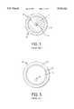
- FIG. 1is a diagrammatic cross-sectional view of a prior art optical fiber having a core doped with a gain species, surrounded by an inner cladding, which in turn is surrounded by an outer cladding;
- FIG. 2is a diagrammatic longitudinal cross-sectional view of a prior art optical fiber aligned with an optical waveguide and coupled to a source of radiation;
- FIG. 3is a longitudinal cross-sectional view of a prior art fiber laser and includes lasing rays propagating within the fiber laser core;
- FIG. 4Ais a simplified diagrammatic cross-sectional view of an optical fiber with line segments denoting rays of different modes within the waveguide;
- FIG. 4Bis a diagrammatic cross-sectional view of the optical fiber of FIG. 4A showing a lower-order mode ray having a bounce angle of approximately 10°;
- FIG. 4Cis a diagrammatic cross-sectional view of the optical fiber of FIG. 4A showing a higher-order mode ray having a bounce angle of approximately 40°;
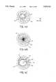
- FIG. 5is a diagrammatic cross-sectional view of a prior art laser having a doped, active core eccentrically located inside of a surrounding inner cladding;
- FIG. 6is a diagrammatic cross-sectional view of an optical fiber, having a waveguide according to the invention, illustrating the projections, in the cross-sectional plane, of a series of ray segments representing a ray propagating along the length of the fiber;
- FIG. 7is a diagram illustrating two graphical representations of an optical ray undergoing internal reflections in a waveguide as it propagates along a fiber;
- FIG. 8is a diagram illustrating the "space-filling tiling" property required for a polygon whose shape is used in a waveguide according to the present invention
- FIG. 9is a portion of a general polygon development
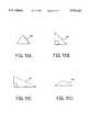
- FIGS. 10A through 10Dare diagrams of optical fiber embodiments for a waveguide cross section of three sides according to the present invention.
- FIGS. 11A through 11Dare diagrams of optical fiber embodiments for a waveguide cross section of four sides according to the present invention.
- FIG. 12is a diagram of an optical fiber embodiment for a waveguide cross section of six sides according to the present invention.
- FIG. 13is a diagrammatic perspective view of a typical application for an optical fiber according to the present invention, showing a laser bar, an optical beam rotating device, focusing optics, and the optical fiber.
- Optical fiber amplifiers and laserscommonly function with optical radiation propagating within the core of a component optical fiber.
- signal or pump radiationis injected at one end of the optical fiber, is confined and guided by the fiber, and emerges from the other fiber end as an amplified signal or as lasing radiation.
- FIG. 1is a cross-sectional view of a circularly-symmetric multiclad optical fiber 10 comprising a core 14, an inner cladding 12 surrounding the core 14 and an outer cladding 16 surrounding the inner cladding 12.
- Core 14can range from 2 to about 10 ⁇ m in diameter for single-mode generation.
- the pump radiationis typically single-mode and can be injected directly into core 14.
- the index of refraction n 1 of core 14is larger than the index of refraction n 2 of the inner cladding 12
- the radiationcan be largely confined within core 14 by means of total internal reflections.
- total internal reflectionswill occur when radiation strikes the core boundary at an angle smaller than a critical angle ⁇ c .
- inner cladding 12functions as a waveguide by means of internal reflections of the radiation occurring at an interface 18 lying between inner cladding 12, with index of refraction n 2 , and outer cladding 16, with a smaller index of refraction n 3 .
- the purpose of inner cladding 12is to confine the injected radiation so that the radiation repeatedly intersects the core 14 as it propagates along the length of fiber 10. With each such intersection with core 14, a portion of the pump radiation is absorbed by an active gain dopant contained within core 14.
- the length of an optical fiberis typically tens of meters so as to produce a large number of these interactions and allow the core to absorb as much pump radiation as possible.
- Optical amplifiersmay make use of fiber configurations, such as that shown in FIG. 1, to couple amplifying radiation into a signal propagating in the fiber core.
- U.S. Pat. No. 3,808,549 issued to Maurerdiscloses an optical communication device comprising a radiation source aligned with an optical fiber.
- the communication deviceincludes an optical fiber 20 and an optical waveguide 32, both shown in longitudinal cross section in FIG. 1 of that patent, here shown as FIG. 2.
- Optical fiber 20comprises an inner transparent cladding layer 22 disposed on the surface of a core 24, and a thin outer cladding layer 26 disposed on the surface of the inner cladding layer 22.
- An output end 25 of optical fiber 20is aligned with an input end 35 of the optical waveguide 32. Radiation generated in core 24 is coupled to the optical waveguide 32.
- the reference patentstates that the refractive index of the outer cladding layer 26 must be sufficiently lower than that of the inner cladding layer 22 so that an appreciable amount of radiation from a source 34 is accepted by and propagated along the core 24.
- the core 24absorbs the radiation as it is reflected back and forth many times from the interface 28.
- the referencefurther states that the length of the optical fiber 20 should be made sufficiently great to permit most of the radiation to be absorbed by the core 24.
- FIG. 2 of the reference patentprovides a cross-sectional side view of a single-mode fiber with associated multimode fiber pumping cavity. This illustration is presented here as FIG. 3.
- An xyz-coordinate system 39is included to aid in discussion.
- a fiber laser 40is comprised of a single-mode core 44 surrounded by a multimode cladding 42 and an outer layer 46, the latter two of which define a pump cavity.
- the indices of refraction for cladding 42 and outer layer 46are chosen so that pump radiation will be totally internally reflected at an interface 48.
- not every mode that is excited in such a structurewill propagate along a path that intersects the core. In fact, skew rays, which carry the bulk of the pump energy, are concentrated in an annular region surrounding the core and therefore never intersect it.
- the core diameterwhich must be small enough to limit radiation propagation in core 14 to single-mode operation, is typically 10 ⁇ m or less.
- the cladding diameterwhich must be large enough to efficiently acquire radiation from a multimode source, is typically 125 to 1100 ⁇ m. What is needed is an optical fiber configuration in which the coupling efficiency can be improved without increasing the size of the fiber core.
- optical fiber amplifiers and fiber systemsincorporate optical fibers having a circular cross section. These systems have sought to improve the optical fiber coupling efficiency without fully appreciating the limitation imposed upon the coupling process when the inner cladding layer is in the form of a rotationally symmetric waveguide.
- a circular waveguideis used to contain and couple radiation into a central core, the resulting distribution of radiation within the waveguide is not isotropic and, therefore, not every radiation mode intersects the core. Consequently, not all the radiation present in the optical fiber is available for absorption by the fiber core.
- Optical fiber 60is a simplified representation of the cross section of a multiclad optical fiber. Propagating radiation is represented by a plurality of rays 61 confined within an inner cladding 62. Because it is impossible to graphically represent the hundreds or even thousands of radiation modes present in a multimode optical fiber structure as illustrated, only a few rays of radiation are shown in FIG. 4A.
- the bounce angle, as seen in the x-y plane, for one radiation modewill generally not be the same as the bounce angle for another radiation mode.
- a higher-order mode ray 61apropagates along optical fiber 60 with a smaller bounce angle (e.g., 10°) as shown in FIG. 4B, while a lower-order mode ray 61b propagates at a larger bounce angle (e.g., 40°) as shown in FIG. 4C.
- the cross section of inner cladding 62is circular, the bounce angle for a particular radiation mode will not change as the radiation propagates along the fiber.
- higher-order mode ray 61apasses through the core region of fiber 60 and may intercept a centrally-located core.
- lower-order mode ray 61bwith the larger bounce angle, does not intercept a core 64 positioned at the center of optical fiber 60.
- any reflected ray consequent to ray 61bdoes not pass through core 64, regardless of the length of fiber 60.
- the various radiation modes propagating within a circular waveguideare not isotropically distributed.
- FIG. 5shows a cross section of an optical fiber laser 70 comprised of a single-mode core 74 surrounded by an inner cladding layer 72.
- Inner cladding layer 72is in turn surrounded by an outer cladding layer 76 which has a lower index of refraction n 3 than the index of refraction n 2 for inner cladding layer 72.
- a protective layer 77may also be provided.
- core 74is eccentrically located inside of inner cladding layer 72.
- the amount of displacement requiredis determined by the condition that a substantial amount of radiation propagating in the inner cladding layer 72 couples into the core 74. This coupling occurs whenever the radiation propagating in the inner cladding layer 72 intersects the core 74 at the displaced position and is absorbed by the core 74.
- the device described in the patenthas achieved an improved coupling efficiency of approximately 27%.
- the change in coupling efficiency caused by a displacement of core 74 from the center of fiber 70results from the fact that the radiation present within a circular waveguide, such as inner cladding 72, is not isotropically distributed throughout the cross section of optical fiber 70, but rather resides in an annular region surrounding the core.
- the second embodiment disclosed by Snitzer et al.had an inner cladding in the form of an elongated slab, preferably rectangular in shape, which was thought to cause the bulk of the modes to pass through the narrowest part of the structure where the core was placed. This structure was remarkably successful compared with the prior art, exhibiting an efficiency in excess of 70 percent.
- the present inventionutilizes double-clad optical fiber configurations which produce a uniform distribution of radiation modes within the inner cladding. Such configurations expose the core to all radiation modes. Further, the core can be positioned essentially anywhere within the inner cladding without affecting the coupling efficiency of the fiber. It has been found that a uniform radiation field is produced when the waveguide region, or inner cladding, of an optical fiber has a geometric shape which meets certain criteria to be discussed.
- the Brightness Theoremholds that, at best, one can only maintain the same radiation intensity across the entire cross section of the inner cladding, and that the radiation intensity cannot be increased locally at the expense of lowering it elsewhere.
- the highest achievable coupling efficiency from inner cladding into coreis given by the ratio of core cross-sectional area to inner cladding cross-sectional area (i.e., A core /A multimode ).
- This disclosureprovides an analysis which shows that this optimal efficiency can be achieved when the cross-section of the fiber waveguide, or inner cladding, is in the shape of one of the several polygons disclosed in this specification.
- FIG. 6illustrates the cross-sectional structure and geometry of an optical fiber 130 according to the present invention.
- the longitudinal dimension of optical fiber 130extends generally along the z-axis of an xyz-coordinate system 129.
- Optical fiber 130is comprised of a core 134 surrounded by an inner cladding 132.
- Core 134comprises a suitable optical host, such as fused silica, which is doped in a well-known manner with a gain material.
- a silica doped with a rare earth element ionsuch as neodymium (Nd 3+ ) or yttrium, present in concentrations of up to 0.5 weight-percent or lower, is used as the core dopant.
- Core 134is generally circular in cross section, although other shapes, such as that of an ellipse, can be used as well.
- Inner cladding 132comprises material having an index of refraction, n 2 , which is smaller than the index of refraction, n 1 , of the core material.
- the cross-sectional shape of inner cladding 132is that of a convex polygon.
- Optical fiber 130also includes an outer cladding 136 comprising a material having an index of refraction, n 3 , smaller than inner cladding index of refraction, n 2 .
- Optical radiationis confined to inner cladding 132 by means of total internal reflection at the interface between it and cladding 136.
- Inner cladding 132functions as a core with respect to outer cladding 136 to couple the radiation into core 134.
- Outer cladding 136is preferably circular in cross section and is preferably made of a low-index fluorinated polymer.
- inner cladding 132is limited to having this particular cross-sectional shape.
- An optical fiber waveguide having any of the disclosed cross-sectional shapeswill induce incoming multimode optical radiation to form into an essentially uniform radiation field within the optical fiber.
- a uniform radiation fieldis meant that the radiation field will have an essentially constant intensity throughout the cross-section of the optical fiber waveguide. Radiation propagating through optical fiber 130 forms into a uniform radiation field because of the geometric properties of the cross-sectional shape of inner cladding 132.
- optical fiber 130Because the radiation field produced is uniform, and all optical rays propagating within optical fiber 130 spend essentially the same fraction of time (approximately A core /A multimode ) propagating within core 134, the optical rays will undergo the same amount of absorption in core 134 as they continue to propagate, regardless of the placement of core 134 within cladding 132. Consequently, the optimal coupling efficiency of optical fiber realized. In comparison, optimal coupling efficiency cannot be realized for a circular waveguide because not all propagating radiation intersects a core if a circular waveguide is used. Optimal coupling efficiency can be attained only if a uniform radiation field is present within the optical fiber waveguide.
- the inventionwill be explained by means of a pictorial depiction of the optical radiation propagating in optical fiber 130.
- the descriptionis simplified with the assumption that inner cladding 132 supports a large number of modes (i.e., more than 1000 modes).
- Propagation of the radiation fieldcan then be represented by an incoherent superposition of classical optical rays.
- a uniform radiation fieldwould then be depicted as a uniform distribution of optical rays lying in an x-y projection plane consisting of the planar cross section of optical fiber 130.
- first optical ray 142 and a second optical ray 142'propagate along fiber 130 in the z-direction, shown in FIG. 6, undergoing a series of reflections from the interface at cladding 132.
- Each reflected rayis represented by a two-dimensional projection of its optical path onto the cross-sectionsl x-y plane. Because optical rays enter inner cladding 132 at different locations and at different angles of incidence to execute different modes, first optical ray 142 and second optical ray 142' will not generally have the same angles of reflection along interface 138.
- inner cladding 132would become entirely crisscrossed with lines representing the reflecting rays produced. It would be impossible to show all subsequent reflections clearly and it could not readily be determined whether a particular inner cladding shape produces a uniform radiation field. To depict subsequent reflections in a manner which allows such a determination to be made, a different method of illustration is used.
- the multiply-folded path followed by an optical ray making successive reflections at the interior surface interfaces of a waveguidecan also be depicted as a straight-line path extending across the interfaces of a succession of adjoining "virtual" waveguides.
- Each successive virtual waveguideis constructed by performing a mirror reflection of the previous waveguide across an interface common to both waveguides.
- FIG. 7shows a waveguide core 110 comprised of a right surface 114, a top surface 112 and a bottom surface 116.
- An optical ray 121i.e., the x-y projection of the optical ray
- a first reflected ray segment 123is produced by a reflection from top surface 112.
- the angle of reflection ⁇is equal to the angle of incidence.
- a second reflected ray segment 125is produced by a reflection from right surface 114 and reflects at an angle ⁇ .
- Propagating optical ray 121 and reflected ray segments 123 and 125can also be represented by means of a straight line consisting of three parts: ray 121, a first virtual reflected ray segment 123a, and a second virtual reflected ray segment 125b.
- Ray segment 123aappears in a first virtual waveguide 110a and corresponds to first reflected ray segment 123.
- Virtual waveguide 110ais constructed by a mirror reflection of waveguide core 110 across the common interface consisting of top surface 112.
- Ray segment 123ais also a mirror reflection of ray segment 123 across the common interface.
- the angle of reflection ⁇ ' for ray segment 123ais the same as the angle of reflection ⁇ for ray segment 123.
- Ray segment 123ais incident on right virtual surface 114a and produces second virtual reflected ray 125b which appears in a second virtual waveguide 110b.
- Virtual waveguide 110bis constructed by a mirror reflection of virtual waveguide 110a across the common interface consisting of right surface 114a.
- Ray 125bcorresponds to ray 125 in waveguide core 110, and the angle of reflection ⁇ ' is equal to the angle of reflection ⁇ for ray 125. This process of construction is continued for the subsequent reflections occurring in the waveguide core 110.
- Propagating ray 142is represented as a folded line in FIG. 6. Reflections occur at the inside surfaces of inner cladding 132, these interfaces being represented by sides 152, 154, 156, and 158. Sides 152 and 154 form a vertex 162, sides 154 and 156 form a vertex 164, sides 156 and 158 form a vertex 166, and sides 158 and 152 form a vertex 168.
- the optical path taken by ray 142is represented as a series of reflected ray segments, denoted by lines and arrowheads.
- Ray 142for example, is incident upon polygon side 152 at an angle ⁇ relative to a surface normal 144.
- a first reflected ray segment 142aleaves side 152 at an angle ⁇ ' to the surface normal 144, where ⁇ ' equals ⁇ .
- First reflected ray segment 142areflects off side 154 to produce a second reflected ray segment 142b.
- Third reflected ray segment 142c, fourth reflected ray segment 142d, and fifth reflected ray segment 142eare produced in a similar manner by reflections off sides 156, 158, and 152 respectively.
- fourth reflected ray segment 142dis incident upon side 152 at a location 152b different from the point of incidence 152a of ray 142
- fifth reflected ray segment 142eoriginates from a different point on side 152 than does first reflected ray segment 142a. Consequently, even though first reflected ray segment 142a does not intersect core 134, a subsequent reflected ray segment, fifth reflected ray segment 142e in this case, does intersect core 134 because successive reflected ray segments cross the two-dimensional cross-sectional plane at different locations.
- This propertyassures that core 134 will eventually be intersected by every optical ray propagating within optical fiber 130, and, as stated earlier, is a consequence of the preferred geometry used for the cross-sectional shape of inner cladding 132.
- any region within the projection planewill be crossed by one of the sequence of reflected rays produced by ray 142. This occurs because successive reflections do not repeat the same path followed in the projection plane by a previous reflection. The successive reflections thus tend to "migrate" across the projection plane.
- This descriptionis equally valid for the propagation of second ray 142', or for any another optical ray injected into optical fiber 130. All such rays will have essentially the same probability of passing through a particular region in the projection plane and all rays will intersect the core many times over its length.
- FIG. 8The alternate method of representing the optical path followed by ray 142 as a straight line is shown in FIG. 8.
- ray 142 and first reflected ray segment 142aare shown as two line segments, both forming a straight line continuing across a reflecting interface depicted by side 152 and a side 152a of an adjacent virtual polygon 140a.
- the angle of incidence ⁇ and the angle of reflection ⁇ 'appear on opposite sides of the reflecting interface.
- Polygon 140ahas been constructed by a mirror reflection across side 152. The relative positions of the sides and vertices of polygon 140a are thus reversed from the positions of the corresponding sides and vertices of the original.
- First reflected ray segment 142ais, in turn, incident upon side 154a. This produces a second reflected ray segment 142b which is a continuation, into a virtual polygon 140b, of the straight line formed by ray 140 and first reflected ray segment 140a.
- Polygon 140bhas been constructed by a mirror reflection of polygon 140a across a side 154a. The sides and vertices of polygon 140b are thus reversed from those of polygon 140a and are thus symmetrical to the sides and vertices of the original.
- the remaining ray pathis comprised of third reflected ray segment 142c passing through a virtual polygon 140c, fourth reflected ray segment 142d passing through a virtual polygon 140d, and fifth reflected ray segment 142e passing into a virtual polygon 140e.
- This succession of virtual polygonshas been constructed by a series of consecutive mirror reflections executed across reflecting interfaces defined by side 156b, side 157c, and side 154d in sequence.
- polygon 140dcan be alternatively constructed by a mirror reflection of polygon 140b across side 158b.
- Each reflected ray segment, such as first reflected ray segment 142a, passing through one of the reflected polygons, such as polygon 140a,represents a reflected ray confined within the inner cladding 132 of FIG. 6.
- the relative position of any reflected ray segment within inner cladding 132e.g., first reflected ray segment 142a
- the relative position of the corresponding ray within a polygoni.e., first reflected ray segment 142a in polygon 140a
- each successive ray segmentis depicted passing through an adjacent polygon, with each successive passage occurring in a different location within the respective polygon, the corresponding reflected ray segment is depicted as passing through a different location within the cross section of inner cladding 132.
- the optical path of the propagating raycan be extended indefinitely in all directions, producing an indefinite number of reflected ray segments. As stated above, if these reflected rays were depicted on the projection plane of FIG. 6, the projection plane would become uniformly covered by the resultant lines. The reflected ray segments, which define the path followed by the propagating ray, thus form into a uniform spatial distribution throughout the projection plane.
- a similar depictioncan be made for the optical path followed by second ray 142', propagating from side 156 and incident upon side 154.
- This optical pathappears in the polygon but, unlike the optical path taken by ray 142, passes into a polygon 140f, into a polygon 140g, and continues into a polygon 140h.
- the reflections produced by second ray 142'will likewise uniformly cover the projection plane, but in a pattern different from the pattern of reflected rays obtained with the sequence of reflections produced by optical ray 142.
- multimode optical radiationpropagating within optical fiber 130 as a large number of optical rays, is induced to form an essentially uniform radiation field. This is a consequence of the property of the convex polygon used for the cross-sectional shape of inner cladding 132.
- the spatial distribution pattern produced by the reflection segments of each optical rayis a uniform distribution.
- a uniform radiation fieldis necessary if all the power in the propagating radiation is to be made available for absorption by the core dopant.
- the uniform fieldcauses each radiation mode to periodically intersect the core and to transfer a portion of its power to the dopant.
- the total amount of power coupled into the coreis related to the length of fiber used for the coupling process, and the concentration-length product which can be adjusted in a well-known manner so as to achieve substantially total absorption at a desired length.
- Each of these spatial distribution patternscan also be represented as a straight-line optical ray extending along an endless planar array of the convex polygon used for the cross-sectional shape of inner cladding 132.
- each reflected ray segment in inner cladding 132is equivalent to one of the ray segments appearing in one of the arrayed polygons.
- the optical rayWhen the straight-line representation of an optical ray passes through an endless series of arrayed identical polygons, the optical ray will produce a uniform spatial distribution of reflected rays within the optical fiber inner cladding.
- the endless array of polygonsfills, or tiles, the plane of the array, all optical ray straight-line representations will pass through an endless series of arrayed polygons.
- the array of polygonstiles the plane such that no spacing is present between adjacent polygons, an inner cladding having a cross section in the shape of this polygon will produce a uniform field from the confined radiation.
- Non-tiling polygonswill leave uncovered spaces in the plane. Not all straight lines will constantly pass through polygons.
- a waveguide having a cross-sectional shape of a non-tiling polygonwill not induce incoming radiation to form into a uniform field. Consequently, the invention relates to a class of shapes having the needed properties which meet two criteria.
- the first criterion for the preferred polygon shapeis derived from a requirement that a planar array formed by repeated mirror reflections of the cross-sectional shape completely fills the plane. Fulfilling this criterion insures that successive reflections of an incident ray will be sustained to allow propagation of a ray oriented in any initial direction. This necessitates that there be no "unfilled space" between adjacent polygon shapes.
- a first corollary to the first criterionis that any shape having a curved side or a convex vertex angle is eliminated from consideration. Accordingly, the required cross-sectional shape is a convex polygon having three or more sides.
- each vertex anglemust be an integral divisor of 360°. This can be explained by first noting that adjacent polygons share a common point. For example, vertices 162, 162a, 162b, 162h, 162g, and 162f all meet at a common point, denoted by ⁇ A ⁇ , in the polygon array of FIG. 8. Similarly, vertices 166b, 166c, and 166d all meet at a common point ⁇ B ⁇ and vertices 168b, 168d, 168j, and 168h all meet at common point ⁇ C ⁇ in the array. Further, each vertex angle at a common point is equal to each other vertex angle at the same common point.
- each of the six vertex angles at common point Amust equal 60°
- each of the three vertex angles at common point Bmust equal 120°
- each of the four vertex angles at a common point Cmust equal 90°.
- the second criterionarises from a further inspection of the common points where three or more vertices are found.
- the polygons surrounding a common pointcan be viewed as having been generated by a series of multiple reflections beginning with an initial polygon and using the common point as a center of rotation for the series of reflections.
- two of the three polygons surrounding common point Bcan be viewed as having been generated from polygon 140b by a first mirror reflection across side 156b to produce polygon 140c, and a second mirror reflection across side 157c to produce polygon 140d.
- a third mirror reflection, across side 158dwill yield the original polygon 140b. That is, three reflections of initial polygon 140b around common point B maps the initial polygon 140b onto itself.
- the number of reflections required to perform this mappingis equal to the number of vertex angles surrounding the common point. In the example given, three reflections are required because 360° divided by vertex angle 120° equals three.
- the second criterion for a polygon shaperequires that the polygon is mapped onto itself when a series of k j mirror reflections is performed about a vertex, where the vertex angle is equal to 360° divided by k j .
- N-sided convex polygon 170The two criteria discussed above can be more generally stated with reference to the diagram of FIG. 9 in which is shown an N-sided convex polygon 170.
- Polygon 170has sides s i and vertices V i where 1 ⁇ i ⁇ N. Further, vertex V i+1 is formed by sides s i and s i+1 . By inspection, it can be seen that, because polygon 170 is closed, vertex V 1 is formed by side S N and side s 1 .
- the vertex angle ⁇ i of each vertex V i of N-sided convex polygon 170must satisfy the condition that
- vertex angles which meet the above conditionare integral divisors of 360°, e.g., 120°, 90°, 72°, 60°, 45°.
- N-sided convex polygon 170further has the property that it is mapped onto itself when a series of k j reflections is executed about any vertex V j .
- This series of reflectionswould include a first reflection across side S j , a second reflection across side s j+1 , a third reflection across side s j , and subsequent reflections performed alternatingly across sides s j+1 and s j until the series of k j reflections has been accomplished.
- the inventionrelates to a class of waveguides having the cross-sectional shape of a convex polygon which meets the requirements that, if a number of such polygons is used to tesselate, or tile, a plane, all of the polygons will fill the available space and fit without overlapping or leaving an intervening space between adjacent polygons, and all of the polygons will be mirror images of one another about any common side.
- Fabrication of an optical cable in accordance with the inventionis accomplished by machining a preform to the desired cross section and then drawing the preform in the method known to those in the art.
- the preferred embodiments for an inner cladding in a double-clad fiber structure according to the present inventionhave cross sections in the shape of a polygon with three, four, or six sides.
- the embodiments having cross sections in the shape of a three-sided polygoninclude an equilateral triangle 182, as shown in FIG. 10A, a right-isosceles triangle 184 as in FIG. 10B, a 30°-60°-90° triangle 186 as shown in FIG. 10C, a and a 30°-30°-120° triangle 188 as shown in FIG. 10D.
- the embodiments having cross sections in the shape of a four-sided polygoninclude a rectangle 192 as shown in FIG. 11A, a square 192' as shown in Fig 11B, a 60° rhombus 194 as shown in FIG. 11C, and a symmetrical quadrangle 196 having opposed vertex angles of 60° and 120° as shown in FIG. 11D.
- An embodiment having a cross section in the shape of a six-sided polygonis that of a regular hexagon 198 as shown in FIG. 12. Even though rectangle 192 meets the criteria found to be inventive here, it is specifically not considered part of the claimed invention.
- a waveguide having the cross section of rectangle 192may be the most flexible in one direction.
- a waveguide having the cross section of square 192'may be easier to fabricate than a waveguide having the cross section of hexagon 198, but less material is removed from a round preform to form hexagon 198 than to form square 192'.
- a waveguide having a triangular cross sectionmay be optimal.
- a laser diode array 210may be used to provide pump power to optical fiber 130 as shown in FIG. 13.
- the output of laser diode array 210is typically converted by means of an intermediate optical system 220 from an array of individual laser beams 212 into a single output beam 232.
- Optical system 220may be an optical fiber laser and geometric coupler as disclosed in U.S. Pat. No. 5,268,978 issued to Po et al.
- Optical system 220is designed to yield a numerical aperture for single output beam 232 which is compatible with the numerical aperture of inner cladding 132 as seen at an input end 131 of optical fiber 130.
- Optical system 220includes a beam collimator 222, for reducing the growth of beams 212 in one azimuth. After collimation, laser beams 212 pass into a plurality of waveguides 225. Each waveguide 225 is positioned proximate a corresponding laser beam 212 as it emerges from beam collimator 222 by means of an alignment block 224. The output ends 227 of the waveguides 225 merge into a stack 226 configured to provide a particular beam geometry.
Landscapes
- Physics & Mathematics (AREA)
- Electromagnetism (AREA)
- Optics & Photonics (AREA)
- Engineering & Computer Science (AREA)
- Plasma & Fusion (AREA)
- General Physics & Mathematics (AREA)
- Lasers (AREA)
- Light Guides In General And Applications Therefor (AREA)
- Optical Couplings Of Light Guides (AREA)
Abstract
Description
A.sub.multimode =P/[B(NA).sup.2 ]
θ.sub.i =360°/k.sub.i, where k.sub.i ≧3.
Claims (32)
Priority Applications (9)
| Application Number | Priority Date | Filing Date | Title |
|---|---|---|---|
| US08/283,226US5533163A (en) | 1994-07-29 | 1994-07-29 | Optical fiber structure for efficient use of pump power |
| RU97103520/28ARU2153214C1 (en) | 1994-07-29 | 1995-07-24 | Fiber-optic structure for effective application of pumping radiation, optical pumping-radiation intensifying system, and fiber-optic structure for intensifying pumping radiation |
| PCT/US1995/009311WO1996004700A1 (en) | 1994-07-29 | 1995-07-24 | Optical fiber structure for efficient use of pump power |
| JP08506582AJP3039993B2 (en) | 1994-07-29 | 1995-07-24 | Optical fiber structure for effective use of pump power |
| CN95194426ACN1084532C (en) | 1994-07-29 | 1995-07-24 | Optical fiber structure for efficient use of pump power |
| CA002196188ACA2196188C (en) | 1994-07-29 | 1995-07-24 | Optical fiber structure for efficient use of pump power |
| DE69503249TDE69503249T2 (en) | 1994-07-29 | 1995-07-24 | STRUCTURE OF OPTICAL FIBERS FOR EFFICIENT USE OF PUMPING PERFORMANCE |
| EP95927387AEP0771481B1 (en) | 1994-07-29 | 1995-07-24 | Optical fiber structure for efficient use of pump power |
| KR1019970700578AKR100241581B1 (en) | 1994-07-29 | 1995-07-24 | Optical fiber structure for efficient use of pump power |
Applications Claiming Priority (1)
| Application Number | Priority Date | Filing Date | Title |
|---|---|---|---|
| US08/283,226US5533163A (en) | 1994-07-29 | 1994-07-29 | Optical fiber structure for efficient use of pump power |
Publications (1)
| Publication Number | Publication Date |
|---|---|
| US5533163Atrue US5533163A (en) | 1996-07-02 |
Family
ID=23085099
Family Applications (1)
| Application Number | Title | Priority Date | Filing Date |
|---|---|---|---|
| US08/283,226Expired - LifetimeUS5533163A (en) | 1994-07-29 | 1994-07-29 | Optical fiber structure for efficient use of pump power |
Country Status (9)
| Country | Link |
|---|---|
| US (1) | US5533163A (en) |
| EP (1) | EP0771481B1 (en) |
| JP (1) | JP3039993B2 (en) |
| KR (1) | KR100241581B1 (en) |
| CN (1) | CN1084532C (en) |
| CA (1) | CA2196188C (en) |
| DE (1) | DE69503249T2 (en) |
| RU (1) | RU2153214C1 (en) |
| WO (1) | WO1996004700A1 (en) |
Cited By (70)
| Publication number | Priority date | Publication date | Assignee | Title |
|---|---|---|---|---|
| US5619522A (en)* | 1995-09-07 | 1997-04-08 | Dube; George | Laser pump cavity |
| US5742633A (en)* | 1996-10-02 | 1998-04-21 | Yale University | Asymmetric resonant optical cavity apparatus |
| US5790735A (en)* | 1995-08-31 | 1998-08-04 | Sdl, Inc. | Optical fibre for improved power coupling |
| WO1998036477A1 (en)* | 1997-02-14 | 1998-08-20 | Alliedsignal Inc. | High-power cladding-pumped broadband fiber source |
| US5873923A (en)* | 1995-11-22 | 1999-02-23 | Lucent Technologies Incorporated | Method of making a cladding pumped fiber structure |
| US6031850A (en)* | 1997-12-22 | 2000-02-29 | Pc Photonics Corporation | Clad pumped, eye-safe and multi-core phase-locked fiber lasers |
| US6061378A (en)* | 1997-05-13 | 2000-05-09 | Cutting Edge Optronics, Inc. | Multiple resonant cavity solid-state laser |
| WO2000027773A1 (en)* | 1998-08-25 | 2000-05-18 | Corning Incorporated | Methods and apparatus for producing optical fiber |
| US6101199A (en)* | 1999-01-05 | 2000-08-08 | Apollo Instruments, Inc. | High power high efficiency cladding pumping fiber laser |
| US6125228A (en)* | 1998-03-04 | 2000-09-26 | Swales Aerospace, Inc. | Apparatus for beam splitting, combining wavelength division multiplexing and demultiplexing |
| WO2000069038A1 (en)* | 1999-05-07 | 2000-11-16 | Mitsubishi Cable Industries, Ltd. | Optical fiber |
| US6157763A (en)* | 1998-01-28 | 2000-12-05 | Sdl, Inc. | Double-clad optical fiber with improved inner cladding geometry |
| US6158436A (en)* | 1999-05-26 | 2000-12-12 | Watson; Wesley S. | Patient constraint |
| US6181466B1 (en) | 1997-08-23 | 2001-01-30 | Pirelle Cavi E Sistemi S.P.A. | Unequal couplers for multimode pumping optical amplifiers |
| US6192713B1 (en) | 1998-06-30 | 2001-02-27 | Sdl, Inc. | Apparatus for the manufacture of glass preforms |
| WO2001038244A1 (en) | 1999-11-23 | 2001-05-31 | Scientific-Atlanta, Inc. | Optical fiber with irregularities at cladding boundary and method of its fabrication |
| US6263003B1 (en) | 1997-02-14 | 2001-07-17 | Alliedsignal Inc. | High-power cladding-pumped broadband fiber source and amplifier |
| US6278816B1 (en) | 1997-12-09 | 2001-08-21 | Scientific-Atlanta, Inc. | Noise reduction technique for cladding pumped optical amplifiers |
| US6324320B1 (en)* | 1998-03-17 | 2001-11-27 | Polaroid Corporation | Optical apparatus for producing a high-brightness multi-laser radiation source |
| WO2002003510A1 (en)* | 2000-07-06 | 2002-01-10 | Alcatel | Cladding-pumped optical fibre and method for making same |
| US20020105997A1 (en)* | 1993-05-28 | 2002-08-08 | Tong Zhang | Multipass geometry and constructions for diode-pumped solid-state lasers and fiber lasers, and for optical amplifier and detector |
| US6438294B1 (en) | 2000-01-18 | 2002-08-20 | Institut National D'optique | Optical fiber pumping apparatus and method for use in pumped optical fiber amplifier and laser systems |
| US6477307B1 (en) | 2000-10-23 | 2002-11-05 | Nufern | Cladding-pumped optical fiber and methods for fabricating |
| US6480659B1 (en)* | 2001-11-14 | 2002-11-12 | Rayteq Photonic Solutions Ltd. | Optic fiber structure for efficient use of optical pump energy in three-level rare-earth doped fiber laser |
| US6483973B1 (en)* | 1999-04-09 | 2002-11-19 | Fitel Usa Corp. | Cladding member for optical fibers and optical fibers formed with the cladding member |
| WO2002097935A1 (en)* | 2001-05-29 | 2002-12-05 | Zhijiang Wang | A cladding-pumped optical fiber laser |
| US6516124B2 (en) | 2001-03-02 | 2003-02-04 | Optical Power Systems Incorporated | Fiber for enhanced energy absorption |
| US20030165008A1 (en)* | 2002-03-04 | 2003-09-04 | The Boeing Company | Fiber amplifier having an anisotropic numerical aperture for efficient coupling of pump energy |
| US6625363B2 (en) | 2001-06-06 | 2003-09-23 | Nufern | Cladding-pumped optical fiber |
| US6636675B2 (en) | 2001-03-12 | 2003-10-21 | Verrillon, Inc. | Optical fiber with reduced cladding-mode loss |
| US20030197921A1 (en)* | 2002-04-18 | 2003-10-23 | Np Photonics, Inc. | Alkali-metal-free phosphate glass with dn/dT = 0 for use in fiber amplifiers |
| US6687445B2 (en) | 2001-06-25 | 2004-02-03 | Nufern | Double-clad optical fiber for lasers and amplifiers |
| JP2004078076A (en)* | 2002-08-22 | 2004-03-11 | Mitsubishi Electric Corp | Optical waveguide and laser amplifier |
| US20040086245A1 (en)* | 2002-03-19 | 2004-05-06 | Farroni Julia A. | Optical fiber |
| US20040109225A1 (en)* | 2002-12-06 | 2004-06-10 | Np Photonics, Inc. | Multi-mode pumped ase source using phosphate and tellurite glasses |
| US20040156401A1 (en)* | 2003-01-27 | 2004-08-12 | Ceramoptec Industries, Inc. | Multi-clad optical fiber lasers and their manufacture |
| US6785304B2 (en)* | 2001-07-24 | 2004-08-31 | Gsi Lumonics, Inc. | Waveguide device with mode control and pump light confinement and method of using same |
| US20040208464A1 (en)* | 2001-07-12 | 2004-10-21 | Hong Po | Optical fiber |
| US6816513B2 (en)* | 2001-04-02 | 2004-11-09 | Apollo Instruments, Inc. | High power high efficiency cladding pumping fiber laser |
| US20040258123A1 (en)* | 2003-06-23 | 2004-12-23 | Zamel James Michael | Diode-pumped solid-state laser gain module |
| US20050013328A1 (en)* | 1998-09-08 | 2005-01-20 | Heinrich Jurgensen | Laser radiation source |
| US20050024716A1 (en)* | 2003-07-15 | 2005-02-03 | Johan Nilsson | Optical device with immediate gain for brightness enhancement of optical pulses |
| US20050078353A1 (en)* | 2003-10-08 | 2005-04-14 | Hiroshi Komine | Brightness enhancement of diode light sources |
| WO2005002008A3 (en)* | 2003-06-25 | 2005-04-28 | Southampton Photonics Ltd | Apparatus for providing optical radiation |
| US20050168804A1 (en)* | 2003-09-29 | 2005-08-04 | Dawson Jay W. | High power 938 nanometer fiber laser and amplifier |
| US20050226580A1 (en)* | 2004-04-08 | 2005-10-13 | Samson Bryce N | Optical fiber for handling higher powers |
| US20050254765A1 (en)* | 2004-05-03 | 2005-11-17 | Martin Seifert | Optical fiber having reduced defect density |
| US20050254764A1 (en)* | 2004-05-12 | 2005-11-17 | Coractive High-Tech Inc. | Double-clad optical fibers |
| US20050265678A1 (en)* | 2004-05-03 | 2005-12-01 | Manyam Upendra H | Optical fiber for delivering optical energy to or from a work object |
| US20060002435A1 (en)* | 2004-06-30 | 2006-01-05 | Kim Chil M | Cladding structure of optical fiber laser |
| US20060245704A1 (en)* | 2004-04-02 | 2006-11-02 | Doukei Nagayasu | Optical fiber amplifier and optical amplifying method employing it, laser oscillating method, laser amplifier and laser oscillator, and laser and laser machining apparatus both employing laser oscillator |
| US20060251367A1 (en)* | 2005-01-21 | 2006-11-09 | Martin Seifert | Fiber optic coupler, optical fiber useful with the coupler and/or a pump light source, and methods of coupling light |
| US20060249491A1 (en)* | 1999-09-01 | 2006-11-09 | Hell Gravure Systems Gmbh | Laser radiation source |
| US20060279793A1 (en)* | 2004-07-30 | 2006-12-14 | Hell Gravure Systems Gmbh | Printing form processing with a plurality of engraving tool tracks forming lines |
| US20070036505A1 (en)* | 2003-09-25 | 2007-02-15 | Martin Seifert | Apparatus and methods for accommodating loops of optical fiber |
| US20070183715A1 (en)* | 2001-12-06 | 2007-08-09 | Syed Murshid | Method and apparatus for spatial domain multiplexing in optical fiber communications |
| WO2008116205A1 (en)* | 2007-03-21 | 2008-09-25 | Nufern | Optical fiber article for handling higher power and method of fabricating or using |
| US20080267229A1 (en)* | 2007-04-26 | 2008-10-30 | Hitachi Cable, Ltd. | Optical fiber, optical fiber production method and optical fiber production system |
| US20100079854A1 (en)* | 2007-08-28 | 2010-04-01 | Fujikura Ltd. | Rare-earth doped core multi-clad fiber, fiber amplifier, and fiber laser |
| US20100079855A1 (en)* | 2008-04-22 | 2010-04-01 | Liang Dong | Multi-clad optical fibers |
| US20130028276A1 (en)* | 2011-03-10 | 2013-01-31 | Coherent, Inc. | High-power cw fiber-laser |
| US8908263B2 (en) | 2011-06-17 | 2014-12-09 | Jds Uniphase Corporation | Large mode area optical waveguide devices |
| CN104470671A (en)* | 2012-06-22 | 2015-03-25 | Ipg光子公司 | Laser drilling method and system for producing shaped holes |
| US9083140B2 (en) | 2011-03-10 | 2015-07-14 | Coherent, Inc. | High-power CW fiber-laser |
| US20190052043A1 (en)* | 2016-02-05 | 2019-02-14 | Nufern | Mode Mixing Optical Fibers and Methods and Systems Using the Same |
| DE10262414B3 (en) | 2001-03-16 | 2019-07-04 | Imra America, Inc. | Passive mode-locked fiber laser |
| US10712320B2 (en)* | 2015-10-14 | 2020-07-14 | Alps Alpine Co., Ltd. | Flow channel structure and measuring device for measurement target liquid |
| US10761267B2 (en) | 2015-08-13 | 2020-09-01 | Nufem | Mode mixing optical fibers and methods and systems using the same |
| US11175449B2 (en) | 2019-01-02 | 2021-11-16 | Lumentum Operations Llc | Optical fiber with variable absorption |
| US11808970B2 (en) | 2019-01-02 | 2023-11-07 | Lumentum Operations Llc | Optical fiber with variable absorption |
Families Citing this family (12)
| Publication number | Priority date | Publication date | Assignee | Title |
|---|---|---|---|---|
| WO1999054765A1 (en) | 1998-04-22 | 1999-10-28 | Sumitomo Electric Industries, Ltd. | Optical fiber, light-emitting module, and optical fiber amplifier |
| RU2255363C1 (en)* | 2003-10-23 | 2005-06-27 | Федеральное государственное унитарное предприятие Научно-производственное предприятие "ИНЖЕКТ" | Optical receiver |
| US7095941B2 (en)* | 2004-10-27 | 2006-08-22 | Schott Corporation | Fused optical fiber optical device system |
| JP2008209603A (en)* | 2007-02-26 | 2008-09-11 | Mitsubishi Cable Ind Ltd | Optical fiber |
| DE102009035375A1 (en) | 2009-03-10 | 2010-09-30 | J-Fiber Gmbh | Method for producing an optical fiber |
| JP5531589B2 (en)* | 2009-12-03 | 2014-06-25 | パナソニック株式会社 | Double clad fiber and fiber laser device |
| US8498044B2 (en)* | 2009-12-22 | 2013-07-30 | Fujikura Ltd. | Amplification optical fiber, and optical fiber amplifier and resonator using the same |
| RU2516166C1 (en)* | 2012-06-25 | 2014-05-20 | Федеральное государственное предприятие "Научно-исследовательский институт "Полюс" им. М.Ф. Стельмаха" | Active element from neodymium-doped yttrium-aluminium garnet, with peripheral absorbing layer |
| CN104338873A (en)* | 2013-07-29 | 2015-02-11 | 贝卡尔特公司 | Straight monofilament for belt |
| RU2654987C1 (en)* | 2017-04-10 | 2018-05-23 | Федеральное государственное бюджетное учреждение науки Институт автоматики и электрометрии Сибирского отделения Российской академии наук (ИАиЭ СО РАН) | Method of selection of transverse modes of multimode fiber laser |
| CN115377780B (en)* | 2022-08-04 | 2024-12-13 | 长飞光纤光缆股份有限公司 | Core-defocused rare-earth-doped optical fibers, their applications, fiber lasers, and fiber amplifiers |
| CN115876915A (en)* | 2022-12-08 | 2023-03-31 | 山东省海洋科学研究院(青岛国家海洋科学研究中心) | An accurate method for judging dominant species of bottom fishery resources in artificial reef areas |
Citations (13)
| Publication number | Priority date | Publication date | Assignee | Title |
|---|---|---|---|---|
| US3808549A (en)* | 1972-03-30 | 1974-04-30 | Corning Glass Works | Optical waveguide light source |
| US4763975A (en)* | 1987-04-28 | 1988-08-16 | Spectra Diode Laboratories, Inc. | Optical system with bright light output |
| US4815079A (en)* | 1987-12-17 | 1989-03-21 | Polaroid Corporation | Optical fiber lasers and amplifiers |
| US4829529A (en)* | 1987-06-15 | 1989-05-09 | Spectra-Physics, Inc. | Laser diode pumped fiber lasers with pump cavity |
| US4955685A (en)* | 1989-02-21 | 1990-09-11 | Sun Microsystems, Inc. | Active fiber for optical signal transmission |
| US5131069A (en)* | 1991-08-12 | 1992-07-14 | Corning Incorporated | Fiber amplifier having modified gain spectrum |
| US5187760A (en)* | 1992-01-23 | 1993-02-16 | General Instrument Corporation | Wavelength selective coupler for high power optical communications |
| US5245690A (en)* | 1991-06-03 | 1993-09-14 | Nippon Telegraph And Telephone Corporation | Optical fiber amplifier including rare earth doped fiber and feedback pump light source control |
| US5263036A (en)* | 1991-01-30 | 1993-11-16 | Cselt-Centro Studi E Laboratori Telecomunicazioni S.P.A. | Pump system for waveguide lasers or amplifiers |
| US5268978A (en)* | 1992-12-18 | 1993-12-07 | Polaroid Corporation | Optical fiber laser and geometric coupler |
| US5291501A (en)* | 1989-12-22 | 1994-03-01 | University Of Southhampton | Optical fibre with doped core and doped inner cladding, for use in an optical fibre laser |
| US5313544A (en)* | 1987-02-18 | 1994-05-17 | Willem Lentink | Wave guide and material comprising wave guides, and its applications and manufacture |
| US5319652A (en)* | 1993-01-29 | 1994-06-07 | The United States Of America As Represented By The Secretary Of The Navy | Super luminescent light source |
Family Cites Families (2)
| Publication number | Priority date | Publication date | Assignee | Title |
|---|---|---|---|---|
| IL100551A0 (en)* | 1991-01-23 | 1992-09-06 | Amoco Corp | Fiber optical amplifier |
| WO1993015536A1 (en)* | 1992-01-31 | 1993-08-05 | Amoco Corporation | Laser-diode pumped lasing fibre scalable to high powers |
- 1994
- 1994-07-29USUS08/283,226patent/US5533163A/ennot_activeExpired - Lifetime
- 1995
- 1995-07-24EPEP95927387Apatent/EP0771481B1/ennot_activeExpired - Lifetime
- 1995-07-24CACA002196188Apatent/CA2196188C/ennot_activeExpired - Fee Related
- 1995-07-24CNCN95194426Apatent/CN1084532C/ennot_activeExpired - Fee Related
- 1995-07-24JPJP08506582Apatent/JP3039993B2/ennot_activeExpired - Lifetime
- 1995-07-24RURU97103520/28Apatent/RU2153214C1/enactive
- 1995-07-24KRKR1019970700578Apatent/KR100241581B1/ennot_activeExpired - Fee Related
- 1995-07-24DEDE69503249Tpatent/DE69503249T2/ennot_activeExpired - Lifetime
- 1995-07-24WOPCT/US1995/009311patent/WO1996004700A1/enactiveIP Right Grant
Patent Citations (13)
| Publication number | Priority date | Publication date | Assignee | Title |
|---|---|---|---|---|
| US3808549A (en)* | 1972-03-30 | 1974-04-30 | Corning Glass Works | Optical waveguide light source |
| US5313544A (en)* | 1987-02-18 | 1994-05-17 | Willem Lentink | Wave guide and material comprising wave guides, and its applications and manufacture |
| US4763975A (en)* | 1987-04-28 | 1988-08-16 | Spectra Diode Laboratories, Inc. | Optical system with bright light output |
| US4829529A (en)* | 1987-06-15 | 1989-05-09 | Spectra-Physics, Inc. | Laser diode pumped fiber lasers with pump cavity |
| US4815079A (en)* | 1987-12-17 | 1989-03-21 | Polaroid Corporation | Optical fiber lasers and amplifiers |
| US4955685A (en)* | 1989-02-21 | 1990-09-11 | Sun Microsystems, Inc. | Active fiber for optical signal transmission |
| US5291501A (en)* | 1989-12-22 | 1994-03-01 | University Of Southhampton | Optical fibre with doped core and doped inner cladding, for use in an optical fibre laser |
| US5263036A (en)* | 1991-01-30 | 1993-11-16 | Cselt-Centro Studi E Laboratori Telecomunicazioni S.P.A. | Pump system for waveguide lasers or amplifiers |
| US5245690A (en)* | 1991-06-03 | 1993-09-14 | Nippon Telegraph And Telephone Corporation | Optical fiber amplifier including rare earth doped fiber and feedback pump light source control |
| US5131069A (en)* | 1991-08-12 | 1992-07-14 | Corning Incorporated | Fiber amplifier having modified gain spectrum |
| US5187760A (en)* | 1992-01-23 | 1993-02-16 | General Instrument Corporation | Wavelength selective coupler for high power optical communications |
| US5268978A (en)* | 1992-12-18 | 1993-12-07 | Polaroid Corporation | Optical fiber laser and geometric coupler |
| US5319652A (en)* | 1993-01-29 | 1994-06-07 | The United States Of America As Represented By The Secretary Of The Navy | Super luminescent light source |
Cited By (123)
| Publication number | Priority date | Publication date | Assignee | Title |
|---|---|---|---|---|
| US6873639B2 (en) | 1993-05-28 | 2005-03-29 | Tong Zhang | Multipass geometry and constructions for diode-pumped solid-state lasers and fiber lasers, and for optical amplifier and detector |
| US20020105997A1 (en)* | 1993-05-28 | 2002-08-08 | Tong Zhang | Multipass geometry and constructions for diode-pumped solid-state lasers and fiber lasers, and for optical amplifier and detector |
| US5790735A (en)* | 1995-08-31 | 1998-08-04 | Sdl, Inc. | Optical fibre for improved power coupling |
| US6073465A (en)* | 1995-08-31 | 2000-06-13 | Sdl, Inc. | Method including making grooves in a fiber preform which is drawn to create fiber with improved mode coupling due to a resultant wandering of the core |
| US5619522A (en)* | 1995-09-07 | 1997-04-08 | Dube; George | Laser pump cavity |
| US5873923A (en)* | 1995-11-22 | 1999-02-23 | Lucent Technologies Incorporated | Method of making a cladding pumped fiber structure |
| US5742633A (en)* | 1996-10-02 | 1998-04-21 | Yale University | Asymmetric resonant optical cavity apparatus |
| WO1998036477A1 (en)* | 1997-02-14 | 1998-08-20 | Alliedsignal Inc. | High-power cladding-pumped broadband fiber source |
| US6263003B1 (en) | 1997-02-14 | 2001-07-17 | Alliedsignal Inc. | High-power cladding-pumped broadband fiber source and amplifier |
| US6061378A (en)* | 1997-05-13 | 2000-05-09 | Cutting Edge Optronics, Inc. | Multiple resonant cavity solid-state laser |
| US6181466B1 (en) | 1997-08-23 | 2001-01-30 | Pirelle Cavi E Sistemi S.P.A. | Unequal couplers for multimode pumping optical amplifiers |
| US6278816B1 (en) | 1997-12-09 | 2001-08-21 | Scientific-Atlanta, Inc. | Noise reduction technique for cladding pumped optical amplifiers |
| US6411762B1 (en) | 1997-12-09 | 2002-06-25 | Scientific-Atlanta, Inc. | Optical fiber with irregularities at cladding boundary |
| US6031850A (en)* | 1997-12-22 | 2000-02-29 | Pc Photonics Corporation | Clad pumped, eye-safe and multi-core phase-locked fiber lasers |
| US6157763A (en)* | 1998-01-28 | 2000-12-05 | Sdl, Inc. | Double-clad optical fiber with improved inner cladding geometry |
| US6345141B1 (en) | 1998-01-28 | 2002-02-05 | Sdl, Inc. | Double-clad optical fiber with improved inner cladding geometry |
| US6125228A (en)* | 1998-03-04 | 2000-09-26 | Swales Aerospace, Inc. | Apparatus for beam splitting, combining wavelength division multiplexing and demultiplexing |
| US6324320B1 (en)* | 1998-03-17 | 2001-11-27 | Polaroid Corporation | Optical apparatus for producing a high-brightness multi-laser radiation source |
| US6510710B1 (en) | 1998-06-30 | 2003-01-28 | Jds Uniphase Corporation | Multi-tube delivery system |
| US6192713B1 (en) | 1998-06-30 | 2001-02-27 | Sdl, Inc. | Apparatus for the manufacture of glass preforms |
| US6604388B1 (en) | 1998-06-30 | 2003-08-12 | Jds Uniphase Corporation | Solid state glass constituent delivery system |
| US6532774B2 (en) | 1998-06-30 | 2003-03-18 | Jds Uniphase Corporation | Method of providing a high level of rare earth concentrations in glass fiber preforms |
| US6523369B1 (en) | 1998-06-30 | 2003-02-25 | Jds Uniphase Corporation | Method of forming an optical fiber |
| US6490889B1 (en) | 1998-06-30 | 2002-12-10 | Jds Uniphase Corporation | Method of forming a glass preform |
| WO2000027773A1 (en)* | 1998-08-25 | 2000-05-18 | Corning Incorporated | Methods and apparatus for producing optical fiber |
| US20060279794A1 (en)* | 1998-09-08 | 2006-12-14 | Hell Gravure Systems Gmbh | Printing form processing with fine and coarse engraving tool processing tracks |
| US20060249488A1 (en)* | 1998-09-08 | 2006-11-09 | Hell Gravure Systems Gmbh | Laser radiation source |
| US20050013328A1 (en)* | 1998-09-08 | 2005-01-20 | Heinrich Jurgensen | Laser radiation source |
| US20060250658A1 (en)* | 1998-09-08 | 2006-11-09 | Hell Gravure Systems Gmbh | Forming a rotogravure cup from small cups |
| US20060255023A1 (en)* | 1998-09-08 | 2006-11-16 | Hell Gravure Systems Gmbh | Processing spot defined by a plurality of laser beams |
| US6101199A (en)* | 1999-01-05 | 2000-08-08 | Apollo Instruments, Inc. | High power high efficiency cladding pumping fiber laser |
| USRE40019E1 (en)* | 1999-01-05 | 2008-01-22 | Zhijiang Wang | High power high efficiency cladding pumping fiber laser |
| US6483973B1 (en)* | 1999-04-09 | 2002-11-19 | Fitel Usa Corp. | Cladding member for optical fibers and optical fibers formed with the cladding member |
| WO2000069038A1 (en)* | 1999-05-07 | 2000-11-16 | Mitsubishi Cable Industries, Ltd. | Optical fiber |
| US6647192B1 (en) | 1999-05-07 | 2003-11-11 | Mitsubishi Cable Industries, Ltd. | Optical fiber |
| US6158436A (en)* | 1999-05-26 | 2000-12-12 | Watson; Wesley S. | Patient constraint |
| US20060249491A1 (en)* | 1999-09-01 | 2006-11-09 | Hell Gravure Systems Gmbh | Laser radiation source |
| US20090168111A9 (en)* | 1999-09-01 | 2009-07-02 | Hell Gravure Systems Gmbh | Printing form processing with fine and coarse engraving tool processing tracks |
| WO2001038244A1 (en) | 1999-11-23 | 2001-05-31 | Scientific-Atlanta, Inc. | Optical fiber with irregularities at cladding boundary and method of its fabrication |
| US6438294B1 (en) | 2000-01-18 | 2002-08-20 | Institut National D'optique | Optical fiber pumping apparatus and method for use in pumped optical fiber amplifier and laser systems |
| US6718106B2 (en)* | 2000-07-06 | 2004-04-06 | Alcatel | Cladding-pumped optical fibre and method for making same |
| WO2002003510A1 (en)* | 2000-07-06 | 2002-01-10 | Alcatel | Cladding-pumped optical fibre and method for making same |
| US20050008313A1 (en)* | 2000-10-23 | 2005-01-13 | Kanishka Tankala | Cladding-pumped optical fiber and methods for fabricating |
| US6477307B1 (en) | 2000-10-23 | 2002-11-05 | Nufern | Cladding-pumped optical fiber and methods for fabricating |
| US7003206B2 (en) | 2000-10-23 | 2006-02-21 | Nufern | Cladding-pumped optical fiber and methods for fabricating |
| US6779364B2 (en) | 2000-10-23 | 2004-08-24 | Nufern | Cladding-pumped optical fiber and methods for fabricating |
| EP1391013A4 (en)* | 2001-03-02 | 2004-12-08 | Ocg Technology Licensing Llc | Fiber for enhanced energy absorption |
| US20040156606A1 (en)* | 2001-03-02 | 2004-08-12 | Hong Po | Fiber for enhanced energy absorption |
| US6516124B2 (en) | 2001-03-02 | 2003-02-04 | Optical Power Systems Incorporated | Fiber for enhanced energy absorption |
| US6950586B2 (en) | 2001-03-02 | 2005-09-27 | Ocg Technology Licensing, Llc | Fiber for enhanced energy absorption |
| US6636675B2 (en) | 2001-03-12 | 2003-10-21 | Verrillon, Inc. | Optical fiber with reduced cladding-mode loss |
| DE10262414B3 (en) | 2001-03-16 | 2019-07-04 | Imra America, Inc. | Passive mode-locked fiber laser |
| US6816513B2 (en)* | 2001-04-02 | 2004-11-09 | Apollo Instruments, Inc. | High power high efficiency cladding pumping fiber laser |
| WO2002097935A1 (en)* | 2001-05-29 | 2002-12-05 | Zhijiang Wang | A cladding-pumped optical fiber laser |
| US6831934B2 (en) | 2001-05-29 | 2004-12-14 | Apollo Instruments, Inc. | Cladding pumped fiber laser |
| US6625363B2 (en) | 2001-06-06 | 2003-09-23 | Nufern | Cladding-pumped optical fiber |
| US20040069019A1 (en)* | 2001-06-25 | 2004-04-15 | Adrian Carter | Double-clad optical fiber for lasers and amplifiers |
| US6687445B2 (en) | 2001-06-25 | 2004-02-03 | Nufern | Double-clad optical fiber for lasers and amplifiers |
| US20040208464A1 (en)* | 2001-07-12 | 2004-10-21 | Hong Po | Optical fiber |
| US20060291788A1 (en)* | 2001-07-12 | 2006-12-28 | Hong Po | Optical fiber |
| US7359604B2 (en) | 2001-07-12 | 2008-04-15 | Ocg Technology Licensing, Llc | Optical fiber |
| US6917742B2 (en) | 2001-07-12 | 2005-07-12 | Ocg Technology Licensing, Llc | Optical fiber |
| US6785304B2 (en)* | 2001-07-24 | 2004-08-31 | Gsi Lumonics, Inc. | Waveguide device with mode control and pump light confinement and method of using same |
| US6480659B1 (en)* | 2001-11-14 | 2002-11-12 | Rayteq Photonic Solutions Ltd. | Optic fiber structure for efficient use of optical pump energy in three-level rare-earth doped fiber laser |
| WO2003042735A1 (en)* | 2001-11-14 | 2003-05-22 | Rayteq Photonic Solutions Ltd. | Optic fiber structure for efficient use of optical pump energy in three-level rare-earth doped fiber laser |
| US7639909B2 (en)* | 2001-12-06 | 2009-12-29 | Florida Institute Of Technology | Method and apparatus for spatial domain multiplexing in optical fiber communications |
| US20070183715A1 (en)* | 2001-12-06 | 2007-08-09 | Syed Murshid | Method and apparatus for spatial domain multiplexing in optical fiber communications |
| US20030165008A1 (en)* | 2002-03-04 | 2003-09-04 | The Boeing Company | Fiber amplifier having an anisotropic numerical aperture for efficient coupling of pump energy |
| US20040086245A1 (en)* | 2002-03-19 | 2004-05-06 | Farroni Julia A. | Optical fiber |
| US7116887B2 (en) | 2002-03-19 | 2006-10-03 | Nufern | Optical fiber |
| US6836356B2 (en)* | 2002-04-18 | 2004-12-28 | Np Photonics, Inc. | Alkali-metal-free phosphate glass with dn/dT ≈ 0 for use in fiber amplifiers |
| US20030197921A1 (en)* | 2002-04-18 | 2003-10-23 | Np Photonics, Inc. | Alkali-metal-free phosphate glass with dn/dT = 0 for use in fiber amplifiers |
| JP2004078076A (en)* | 2002-08-22 | 2004-03-11 | Mitsubishi Electric Corp | Optical waveguide and laser amplifier |
| US20040109225A1 (en)* | 2002-12-06 | 2004-06-10 | Np Photonics, Inc. | Multi-mode pumped ase source using phosphate and tellurite glasses |
| US20040156401A1 (en)* | 2003-01-27 | 2004-08-12 | Ceramoptec Industries, Inc. | Multi-clad optical fiber lasers and their manufacture |
| US6959022B2 (en)* | 2003-01-27 | 2005-10-25 | Ceramoptec Gmbh | Multi-clad optical fiber lasers and their manufacture |
| US20040258123A1 (en)* | 2003-06-23 | 2004-12-23 | Zamel James Michael | Diode-pumped solid-state laser gain module |
| US7170919B2 (en) | 2003-06-23 | 2007-01-30 | Northrop Grumman Corporation | Diode-pumped solid-state laser gain module |
| US20070104438A1 (en)* | 2003-06-25 | 2007-05-10 | Spi Lasers Uk Limited | Apparatus for providing optical radiation |
| US7421175B2 (en) | 2003-06-25 | 2008-09-02 | Spi Lasers Uk Limited | Apparatus for providing optical radiation |
| WO2005002008A3 (en)* | 2003-06-25 | 2005-04-28 | Southampton Photonics Ltd | Apparatus for providing optical radiation |
| US20050024716A1 (en)* | 2003-07-15 | 2005-02-03 | Johan Nilsson | Optical device with immediate gain for brightness enhancement of optical pulses |
| US20070036505A1 (en)* | 2003-09-25 | 2007-02-15 | Martin Seifert | Apparatus and methods for accommodating loops of optical fiber |
| US7400812B2 (en) | 2003-09-25 | 2008-07-15 | Nufern | Apparatus and methods for accommodating loops of optical fiber |
| US7038844B2 (en) | 2003-09-29 | 2006-05-02 | The Regents Of The University Of California | High power 938 nanometer fiber laser and amplifier |
| US20050168804A1 (en)* | 2003-09-29 | 2005-08-04 | Dawson Jay W. | High power 938 nanometer fiber laser and amplifier |
| US7034992B2 (en)* | 2003-10-08 | 2006-04-25 | Northrop Grumman Corporation | Brightness enhancement of diode light sources |
| US20050078353A1 (en)* | 2003-10-08 | 2005-04-14 | Hiroshi Komine | Brightness enhancement of diode light sources |
| WO2005041262A3 (en)* | 2003-10-08 | 2005-08-18 | Northrop Grumman Corp | Brightness enhancement of diode light sources |
| CN1774843B (en)* | 2004-04-02 | 2010-04-14 | 松下电器产业株式会社 | Optical amplification fiber, optical amplification method using same, laser oscillation method, laser amplification device, laser oscillation device, laser device using laser oscillation device, and laser processing machine |
| US20060245704A1 (en)* | 2004-04-02 | 2006-11-02 | Doukei Nagayasu | Optical fiber amplifier and optical amplifying method employing it, laser oscillating method, laser amplifier and laser oscillator, and laser and laser machining apparatus both employing laser oscillator |
| US7283293B2 (en) | 2004-04-02 | 2007-10-16 | Matsushita Electric Industrial Co., Ltd. | High efficiency optical amplifying fiber |
| US20050226580A1 (en)* | 2004-04-08 | 2005-10-13 | Samson Bryce N | Optical fiber for handling higher powers |
| US20050254765A1 (en)* | 2004-05-03 | 2005-11-17 | Martin Seifert | Optical fiber having reduced defect density |
| US7317857B2 (en) | 2004-05-03 | 2008-01-08 | Nufem | Optical fiber for delivering optical energy to or from a work object |
| US7483610B2 (en) | 2004-05-03 | 2009-01-27 | Nufern | Optical fiber having reduced defect density |
| US20050265678A1 (en)* | 2004-05-03 | 2005-12-01 | Manyam Upendra H | Optical fiber for delivering optical energy to or from a work object |
| US20050254764A1 (en)* | 2004-05-12 | 2005-11-17 | Coractive High-Tech Inc. | Double-clad optical fibers |
| US20060002435A1 (en)* | 2004-06-30 | 2006-01-05 | Kim Chil M | Cladding structure of optical fiber laser |
| US7136567B2 (en) | 2004-06-30 | 2006-11-14 | Paichai University Industry-Academic Cooperation Foundation | Cladding structure of optical fiber laser |
| US20060279793A1 (en)* | 2004-07-30 | 2006-12-14 | Hell Gravure Systems Gmbh | Printing form processing with a plurality of engraving tool tracks forming lines |
| US20060251367A1 (en)* | 2005-01-21 | 2006-11-09 | Martin Seifert | Fiber optic coupler, optical fiber useful with the coupler and/or a pump light source, and methods of coupling light |
| US7412135B2 (en) | 2005-01-21 | 2008-08-12 | Nufern | Fiber optic coupler, optical fiber useful with the coupler and/or a pump light source, and methods of coupling light |
| US9352996B2 (en) | 2007-03-21 | 2016-05-31 | Nufern | Optical fiber article for handling higher power and method of fabricating or using |
| US20100008634A1 (en)* | 2007-03-21 | 2010-01-14 | Nufern | Optical fiber article for handling higher power and method of fabricating or using |
| WO2008116205A1 (en)* | 2007-03-21 | 2008-09-25 | Nufern | Optical fiber article for handling higher power and method of fabricating or using |
| US20080267229A1 (en)* | 2007-04-26 | 2008-10-30 | Hitachi Cable, Ltd. | Optical fiber, optical fiber production method and optical fiber production system |
| US20100079854A1 (en)* | 2007-08-28 | 2010-04-01 | Fujikura Ltd. | Rare-earth doped core multi-clad fiber, fiber amplifier, and fiber laser |
| US20100079855A1 (en)* | 2008-04-22 | 2010-04-01 | Liang Dong | Multi-clad optical fibers |
| US8213077B2 (en) | 2008-04-22 | 2012-07-03 | Imra America, Inc. | Multi-clad optical fibers |
| US8736955B2 (en) | 2008-04-22 | 2014-05-27 | Imra America, Inc. | Multi-clad optical fibers with corrugated boundary at pump cladding |
| US20130028276A1 (en)* | 2011-03-10 | 2013-01-31 | Coherent, Inc. | High-power cw fiber-laser |
| US9014220B2 (en)* | 2011-03-10 | 2015-04-21 | Coherent, Inc. | High-power CW fiber-laser |
| US9083140B2 (en) | 2011-03-10 | 2015-07-14 | Coherent, Inc. | High-power CW fiber-laser |
| US8908263B2 (en) | 2011-06-17 | 2014-12-09 | Jds Uniphase Corporation | Large mode area optical waveguide devices |
| CN104470671A (en)* | 2012-06-22 | 2015-03-25 | Ipg光子公司 | Laser drilling method and system for producing shaped holes |
| US10761267B2 (en) | 2015-08-13 | 2020-09-01 | Nufem | Mode mixing optical fibers and methods and systems using the same |
| US11287572B2 (en) | 2015-08-13 | 2022-03-29 | Nufern | Mode mixing optical fibers and methods and systems using the same |
| US10712320B2 (en)* | 2015-10-14 | 2020-07-14 | Alps Alpine Co., Ltd. | Flow channel structure and measuring device for measurement target liquid |
| US20190052043A1 (en)* | 2016-02-05 | 2019-02-14 | Nufern | Mode Mixing Optical Fibers and Methods and Systems Using the Same |
| US10630040B2 (en)* | 2016-02-05 | 2020-04-21 | Nufern | Mode mixing optical fibers and methods and systems using the same |
| US11175449B2 (en) | 2019-01-02 | 2021-11-16 | Lumentum Operations Llc | Optical fiber with variable absorption |
| US11808970B2 (en) | 2019-01-02 | 2023-11-07 | Lumentum Operations Llc | Optical fiber with variable absorption |
Also Published As
| Publication number | Publication date |
|---|---|
| DE69503249D1 (en) | 1998-08-06 |
| KR100241581B1 (en) | 2000-02-01 |
| CA2196188C (en) | 2001-11-27 |
| CN1084532C (en) | 2002-05-08 |
| WO1996004700A1 (en) | 1996-02-15 |
| CN1154764A (en) | 1997-07-16 |
| CA2196188A1 (en) | 1996-02-15 |
| KR970705207A (en) | 1997-09-06 |
| JP3039993B2 (en) | 2000-05-08 |
| DE69503249T2 (en) | 1998-10-29 |
| EP0771481A1 (en) | 1997-05-07 |
| JPH10503885A (en) | 1998-04-07 |
| EP0771481B1 (en) | 1998-07-01 |
| RU2153214C1 (en) | 2000-07-20 |
Similar Documents
| Publication | Publication Date | Title |
|---|---|---|
| US5533163A (en) | Optical fiber structure for efficient use of pump power | |
| US5418880A (en) | High-power optical fiber amplifier or laser device | |
| US6831934B2 (en) | Cladding pumped fiber laser | |
| EP0865620B1 (en) | Method and apparatus for side pumping an optical fiber | |
| CA1324517C (en) | Optical fiber lasers and amplifiers | |
| US6608951B1 (en) | Optical fiber amplifiers and lasers and optical pumping device therefor | |
| CA2127288C (en) | Optical fiber laser and geometric coupler | |
| EP1242325B1 (en) | Optical fiber with irregularities at cladding boundary and method of its fabrication | |
| US7437041B2 (en) | Ring core fiber | |
| JP5876612B2 (en) | Fiber optic coupler for combining a signal beam with a non-circular light beam | |
| US5933437A (en) | Optical fiber laser | |
| JPH07106671A (en) | Device pumping plane-form waveguide path array | |
| US6816513B2 (en) | High power high efficiency cladding pumping fiber laser | |
| JP3913959B2 (en) | Amplifying optical fiber | |
| CN120215015B (en) | Multi-core all-solid-state antiresonant fiber and multi-wavelength fiber laser system | |
| CA2239619C (en) | Method and apparatus for side pumping an optical fiber |
Legal Events
| Date | Code | Title | Description |
|---|---|---|---|
| AS | Assignment | Owner name:POLAROID CORPORATION, MASSACHUSETTS Free format text:ASSIGNMENT OF ASSIGNORS INTEREST;ASSIGNOR:MUENDEL, MARTIN H.;REEL/FRAME:007119/0193 Effective date:19940831 | |
| STCF | Information on status: patent grant | Free format text:PATENTED CASE | |
| FEPP | Fee payment procedure | Free format text:PAYER NUMBER DE-ASSIGNED (ORIGINAL EVENT CODE: RMPN); ENTITY STATUS OF PATENT OWNER: LARGE ENTITY Free format text:PAYOR NUMBER ASSIGNED (ORIGINAL EVENT CODE: ASPN); ENTITY STATUS OF PATENT OWNER: LARGE ENTITY | |
| AS | Assignment | Owner name:SDL, INC., CALIFORNIA Free format text:ASSIGNMENT OF ASSIGNORS INTEREST;ASSIGNOR:POLAROID CORPORATION;REEL/FRAME:009901/0310 Effective date:19990415 | |
| FPAY | Fee payment | Year of fee payment:4 | |
| AS | Assignment | Owner name:JDS UNIPHASE CORPORATION, CALIFORNIA Free format text:ASSIGNMENT OF ASSIGNORS INTEREST;ASSIGNOR:SDL, INC.;REEL/FRAME:012795/0609 Effective date:20020306 | |
| FEPP | Fee payment procedure | Free format text:PAYER NUMBER DE-ASSIGNED (ORIGINAL EVENT CODE: RMPN); ENTITY STATUS OF PATENT OWNER: LARGE ENTITY Free format text:PAYOR NUMBER ASSIGNED (ORIGINAL EVENT CODE: ASPN); ENTITY STATUS OF PATENT OWNER: LARGE ENTITY | |
| FPAY | Fee payment | Year of fee payment:8 | |
| FPAY | Fee payment | Year of fee payment:12 | |
| REMI | Maintenance fee reminder mailed | ||
| FEPP | Fee payment procedure | Free format text:PAYER NUMBER DE-ASSIGNED (ORIGINAL EVENT CODE: RMPN); ENTITY STATUS OF PATENT OWNER: LARGE ENTITY Free format text:PAYOR NUMBER ASSIGNED (ORIGINAL EVENT CODE: ASPN); ENTITY STATUS OF PATENT OWNER: LARGE ENTITY |