US5533029A - Cellular digital packet data mobile data base station - Google Patents
Cellular digital packet data mobile data base stationDownload PDFInfo
- Publication number
- US5533029A US5533029AUS08/461,618US46161895AUS5533029AUS 5533029 AUS5533029 AUS 5533029AUS 46161895 AUS46161895 AUS 46161895AUS 5533029 AUS5533029 AUS 5533029A
- Authority
- US
- United States
- Prior art keywords
- cdpd
- amps
- mdbs
- data
- mobile
- Prior art date
- Legal status (The legal status is an assumption and is not a legal conclusion. Google has not performed a legal analysis and makes no representation as to the accuracy of the status listed.)
- Expired - Lifetime
Links
Images


Classifications
- H—ELECTRICITY
- H04—ELECTRIC COMMUNICATION TECHNIQUE
- H04W—WIRELESS COMMUNICATION NETWORKS
- H04W88/00—Devices specially adapted for wireless communication networks, e.g. terminals, base stations or access point devices
- H04W88/08—Access point devices
- H04W88/10—Access point devices adapted for operation in multiple networks, e.g. multi-mode access points
- H—ELECTRICITY
- H04—ELECTRIC COMMUNICATION TECHNIQUE
- H04W—WIRELESS COMMUNICATION NETWORKS
- H04W48/00—Access restriction; Network selection; Access point selection
- H04W48/08—Access restriction or access information delivery, e.g. discovery data delivery
- H—ELECTRICITY
- H04—ELECTRIC COMMUNICATION TECHNIQUE
- H04W—WIRELESS COMMUNICATION NETWORKS
- H04W72/00—Local resource management
- H04W72/02—Selection of wireless resources by user or terminal
Definitions
- This inventionrelates generally to wireless communication systems. More particularly, the invention relates to cellular base stations supporting transmission and reception of data, fax, and voice signals.
- Mobile wireless communication of analog voice signalswas initially carried by half duplex radio systems.
- citizens Band radioone type of mobile wireless radio, uses amplitude modulation (AM) upon a carrier frequency to transmit or receive voice signals in a half duplex manner.
- Other mobile wireless radiosused frequency modulation (FM) within a given carrier frequency range in order to transmit or receive voice signals, half duplex, achieving improved noise characteristics.
- FMfrequency modulation
- a disadvantage attributable to these systemswas that once a user was beyond a certain range of a given base antenna, the radio channel for a given carrier frequency was inoperative. Another disadvantage was that wireless half duplex voice communication was unacceptable to most consumers. The consumer wanted a wireless duplex voice communication system similar to his or her wired home telephone.
- AMPSAdvanced Mobile Phone Service
- AT&Tthe AMPS cellular network uses the FCC assigned carrier frequency range of 800 to 900 MHz.
- AMPS automobile cellular unitswere first permanently attached to the user's car. Automobile cellular units transmitted voice signals to a cellular base station within a given cell using one watt of power. Hand-held cellular units using battery power supplies were later introduced and transmitted voice signals to a cellular base station within a given cell using one quarter watt of transmit power. Because hand held cellular units operated from a battery power supply, the power consumed by the cellular phones became critical.
- a cellular phoneWhen a cellular phone is powered on and waiting to receive a phone call, it is in a stand-by mode consuming less power than in an active mode.
- the hand held unitwhen the hand held unit is in a stand-by mode, it constantly listens for its registration number in order to become active and receive a phone call.
- the stand-by modealthough lower in power than the active communication mode, continuously uses a considerable amount of power. It is desirable to further decrease the amount of power used in the stand-by mode in order to further increase the time the cellular unit requires for recharging or replacing batteries.
- the human analog voicewas the signal that the AMPS system was first designed to communicate.
- the AMPS systemwas optimized for carrying as many analog voice signals within a given bandwidth of a channel as possible. Mobility of the cellular telephone using low power mobile units, FM modulation, and the higher carrier frequency range (800 MHz-900 MHz) is achieved through a cellular arrangement of antennas whereby a user's signal is handed off to the next cell site as he or she moves into a different cell area. This cellular handoff can cause a temporary loss in transmission or reception. However, temporarily losing a voice signal is not critical because a user knows when there is a signal loss and can retransmit the voice information. However, signal loss, even though temporary, poses special problems for transmission of digital data. Some other AMPS mobile cellular problems causing a loss in a voice signal are fading signal strength, reflections, Rayleigh fading, and cellular dead spots.
- the AMPS voice cellular systemis being used to transmit digital data in the form of Circuit Switched Cellular Data across AMPS carrier channels.
- Raw (baseband) digital datais converted so that it can be transmitted and received across the analog AMPS system.
- One disadvantage to using the AMPS systemis that a narrow channel bandwidth and errors in transmission limit the baud rate of transmitting and receiving digital data.
- Another disadvantage of using AMPS to communicate digital datais that movement of the subscriber unit may cause a cellular handoff to occur, thus causing a loss of the digitally transmitted or received information. Loss of digital data may corrupt a data file such that it is useless. Other losses of the raw digital data may be caused by other problems of the AMPS mobile cellular system.
- Another wireless communication deviceis a pager.
- Most pagersuse simplex or one way communication receiving only a limited amount of information such as a telephone number. Most pagers display only information to a user on demand and perform no other function. Because only one way communication is required, an acknowledgement is not returned by the pager to the original sender. In many cases it is desirable that a sending party receive an acknowledgement minimally, telling him or her that their page message was received. In some cases it may be appropriate to respond by leaving a return page message.
- a disadvantage of present paging systemsis that acknowledgment and return pages are not widely available because simplex paging is more commercialized than other paging modes.
- Another disadvantage of present pagersis that a displayed telephone number is not automatically and electronically dialed directly on a telephone. A user reads the telephone number from a pager's display and manually dials the number on a telephone in order to contact the paging party. It is desirable for a wireless pager to have the capability of automatically dialing a received telephone number on a wireless cellular telephone via electronic means, thus integrating the features of a wireless cellular telephone with that of a duplex pager.
- Fax-modem hardware and firmware in conjunction with fax and data communication application softwarehave the capability of sending digital data over various modem protocols as well as sending facsimile data by using the various facsimile protocols.
- Fax or data communication application softwaremay operate on different hardware such as home or portable computer, personal communicator, personal digital assistant, or other electronic devices.
- modem protocols for standard modulated dataare CCITT V. 22bis, CCITT V. 23, CCITT V.32, Bell103, and Bell212A.
- Modem protocols that include error controlinclude CCITT V.42, MNP2, MNP3, MNP4, and MNP10.
- Modem protocols that provide data compressionare CCITT V. 42bis and MNP5.
- Facsimile protocolsinclude CCITT V.21, CCITT V.27ter, CCITT V.29, CCITT T.4, CCITT T.30, CCITT T.35, Class IEIA/TIA 578, Class I-EIA 592, and Class II-EIA 578SP2188.
- a fax-modemaccepts raw (baseband) digital data from an electronic device over an internal data bus or external RS-232 port. Raw digital data is converted and modulated into data of a given protocol for transmission onto a standard telephone line. Data received from the telephone line can be converted from the modulated form into raw digital data that can be interpreted by the hardware, firmware and application software.
- a disadvantage of present fax-modemsis that most require a wire connection to a telephone line.
- Present methods of providing wireless capability for a fax-modemtake the modulated analog modem output signal from a fax-modem and input this into an AMPS conversion unit.
- the AMPS conversion unitconverts and modulates the transmitted analog modem output signal into a different analog form for transmission onto the AMPS network
- the analog modem output signalis converted into what is called Circuit Switched Cellular Data.
- Received AMPS signalscan be converted from Circuit Switched Cellular Data by the AMPS conversion unit into analog modem input signals that the fax-modem can receive.
- fax-modemsdo not directly convert and modulate raw digital data into an analog signal for transmission onto the AMPS cellular network.
- a disadvantage of present methods of providing wireless fax-modem capabilityis that they require additional devices to send or receive fax and digital data over the AMPS cellular network. Another disadvantage is that more power is necessary for additional components, such as the AMPS conversion unit. Another disadvantage is that a user must carry the portable computer, fax-modem, and AMPS conversion unit to provide wireless fax-modem capability. It is desirable to incorporate a fax-modem and AMPS conversion unit into one unit providing the capability of sending Circuit Switched Cellular Data across the AMPS network.
- a disadvantage of using Circuit Switched Cellular Data communication across an AMPS systemis the requirement of the mobile unit to be stationary to avoid losing data from fading or cellular handoff associated with a non-stationary mobile AMPS communication. Thus, a mobile unit should avoid being moved even slightly when performing communication of Circuit Switched Cellular Data using the AMPS network.
- An object of the present inventionis to facilitate the use of a cellular digital packet data (CDPD) mobile data base station with existing advanced cellular (AMPS) facilities.
- CDPDdigital packet data
- AMPSadvanced cellular
- a further object of the present inventionis to use AMPS communication channels for CDPD communication in a manner entirely transparent to the AMPS system.
- Still a further object of the present inventionis to share front end equipment such as antennas, duplexers, and amplifiers with existing AMPS systems in a manner non-intrusive upon the operation of that AMPS system.
- An additional object of the present inventionis to reduce the size of the elements necessary for a CDPD mobile data base station.
- Yet another object of the present inventionis to provide modifications and expansion of the MDBS without impacting the associated AMPS system.
- a mobile data base stationconfigured to transfer cellular digital packet data between a mobile subscriber and an external communication network.
- the mobile data base stationincludes a controller board operatively connected to the external communication network via a data link and a transceiver board providing a radio link to a mobile subscriber.
- the transceiver boardis separate and distinct from the controller board.
- Another aspect of the present inventionis a method for conveying data from a network management system to a mobile data base station.
- the methodincludes the steps of encoding instruction data according to a predetermined MDBS utility protocol (MUP).
- MUPMDBS utility protocol
- the instruction datais further encoded according to a second protocol and then transferred over a DS0 line.
- the twice-encoded datais received at least at one MDBS and decoded according to both protocols so that the instructions can be carried out at the MDBS.
- An additional aspect of the present inventionis a method of operating a CDPD system having at least one mobile data base station associated with an AMPS system and connected via radio frequency link to a mobile end station.
- the methodincludes the steps of detecting at the MDBS all AMPS communications on all radio frequency channels associated with that AMPS system. From this data a list of channels is derived based upon AMPS use.
- the MDBSthen sends the list of channels to any mobile end system within range of the MDBS.
- Each of the mobile end systems receiving the listed dataselects channels for CDPD use based upon the information in the list.
- a further aspect of the present inventionis a CDPD system associated with an AMPS system having at least one mobile data base station
- the MDBSincludes means for detecting AMPS communications on radio frequency channels encompassed within the AMPS system.
- the MDBSalso includes means for deriving a list based upon AMPS use of the radio frequencies and means for periodically adjusting that list in response to AMPS use.
- the MDBSfurther includes means for sending data regarding the list to mobile end systems within range of the MDBS.
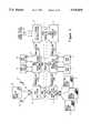
- FIG. 1is a block diagram of a CDPD system.
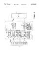
- FIG. 2is a block diagram comparing a CDPD system to an AMPS system.
- FIG. 3is a perspective drawing of a chassis containing a mobile data base station.
- FIG. 4is a block diagram of the overall MDBS architecture.
- FIG. 5is a block diagram showing the interconnections between the MDBS and shared AMPS front end equipment.
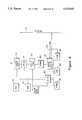
- FIG. 6is a block diagram of the architecture of the Sniffer/modem/transceiver board (SNODEM).
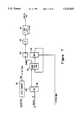
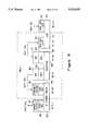
- FIG. 7is a block diagram showing the functional elements in a delta-sigma modulator contained on the SNODEM board.
- FIG. 8is a block diagram of the control computer architecture.
- FIG. 9is a block diagram/flow chart of protocols carried out in the CDPD communication process and correlation of that protocol to elements in the MDBS.
- FIG. 10is a block diagram illustrating connections between a mobile data base station and a network controller sending instruction data to that MDBS.
- CDPDCellular Digital Packet Data
- the base unit, mobile data base station (MDBS 1, as illustrated in FIG. 1), of the preferred CDPD system (MAV)utilize an channel within an AMPS cell to establish a link and communicate to a user's mobile end system.
- the MDBSmay be applicable to other frequencies outside of AMPS that open up to it.
- the mobile end system (M-ES 2)is a portable computer, handset or other portable electronic device containing a subscriber communication unit.
- the MDBSserves as a communication link between the user of the M-ES 2 and a service provider's network of wire lines, microwave links, satellite links, AMPS cellular links, or other CDPD links (such as mobile data intermediate system MD-IS 3, intermediate systems 4, 5, 6) to convey data to another mobile end system, computer network, or non-mobile or fixed end-user system (F-ES 7, 8).
- a service provider's network of wire lines, microwave links, satellite links, AMPS cellular links, or other CDPD linkssuch as mobile data intermediate system MD-IS 3, intermediate systems 4, 5, 6) to convey data to another mobile end system, computer network, or non-mobile or fixed end-user system (F-ES 7, 8).
- the CDPD networkis designed to operate as an extension of existing communication networks, such as AMPS networks and the internet network. From the mobile subscriber's perspective, the CDPD network is simply a wireless mobile extension of traditional networks.
- the CDPD networkshares the transmission facilities of existing AMPS networks and provides a non-intrusive, packet-switched data service that does not impact AMPS service. In effect, the CDPD network is entirely transparent to the AMPS network, which is "unaware" of the CDPD function.
- the CDPD systememploys connectionless network services (CLNS) in which the network routes each data packet individually, based on the destination address carried in the packet and knowledge of current network topology.
- CLNSconnectionless network services
- the packetized nature of the data transmissions from a mobile end system 2allows many CDPD users to share a common channel, accessing the channel only when they have data to send and otherwise leaving it available to other CDPD users.
- the multiple access nature of the systemmakes it possible to provide substantial CDPD coverage to many users simultaneously with the installation of only one CDPD station in a given sector (transmitting range and area of a standard AMPS base station transceiver).
- the airlink interface portion of the CDPD networkconsists of a set of cells.
- a cellis defined by the geographical boundaries within the RF transmission range from a fixed transmission site such as MDBS 1, which can be received at acceptable levels of signal strength by mobile subscribers such as M-ES 2.
- the transmitter supporting the cellmay be located centrally within the cell, with transmission carried out via an omni-directional antenna, or the transmitter may be located at the edge of a cell and transmitted via a directional antenna. This second type of cell is also referred to as a sector. In typical configurations, the transmitters for several sectors are co-located.
- the area served by a set of cellshave some area overlap, so that a roaming mobile end system can maintain continuous service by switching from one cell to an adjacent cell in a manner roughly analogous to the standard hand-off in an AMPS system.
- the two cellsare considered to be adjacent if an M-ES can maintain continuous service by switching from one cell to the other. This switching process is called cell transfer, and is done independently of normal AMPS hand-off procedures.
- the interface (A) between the mobile end system 2 and the MDBS 1is an "air interface" constituted by a radio frequency link using standard AMPS frequencies.
- the MDBS 1is connected to other mobile data base stations through a mobile data intermediate system (MD-IS) 3.
- MD-ISmobile data intermediate system
- a number of mobile data base stationscan be under the control of a single mobile data intermediate system.
- the mobile data intermediate systemsare connected to each other through intermediate systems such as 4 and 5 in FIG. 1.
- the intermediate systemsare constituted by at least one node connected to more than one sub-network (such as an MD-IS).
- the intermediate systemhas a primary role of forwarding data from one sub-network to another.
- the mobile data intermediate system 3performs data packet routing based on knowledge of the current location of each mobile end system within the range of the mobile data base stations under the control of the MD-IS.
- the MD-ISis the only network entity that is "aware" of the location of any of the mobile end systems.
- a CDPD-specific Mobile Network Location Protocol (MNLP)is operated between each MD-IS (through the intermediate system) to exchange location information regarding the mobile end systems.
- MNLPCDPD-specific Mobile Network Location Protocol
- the overall CDPD networkis controlled by a network management system (NMS) 10 having an interface with at least one mobile data intermediate system 3.
- NMSnetwork management system
- programming instructionscan be transmitted from the NMS 10 through the MD-IS 3 to any number of mobile data base stations under the proper conditions.
- Such programming instructionscan be used to convey useful network data to the MDBS, as well as configuring the operation of an MDBS with respect to such critical features as maintaining channel queues.
- the NMSalso controls other CDPD system characteristics such as the timing of paging messages to coincide with the non-dormant periods of the M-ES hand-sets.
- One advantage of the present inventionis the capability of providing operating instructions to mobile data base stations from the NMS 10 through an MD-IS 3, or by a direct connection to the MDBS as is outlined in the detailed description of the MDBS architecture. The functions and protocol as carried out by each of the mobile end systems and the mobile data base station are explained in greater detail later herein.
- FIG. 2provides a comparison between the CDPD network illustrated in FIG. 1 and the standard AMPS network.
- the MDBS 1is the CDPD equivalent to an AMPS base station 21. Both serve as links to mobile users, 2, 2', and 2" for the CDPD system and 22, 22' and 22" for AMPS users. As previously indicated in U.S. patent application Ser. No. 08/117,913, filed Sep. 8, 1993, both AMPS and CDPD functions are preferably handled by the same hand-set or end system equipment. Also, the MDBS 1 is preferably located with the AMPS base station 21 as be will explained in greater detail later.
- the mobile data intermediate system 3which acts as a local controller for the mobile data base stations connected thereto is equivalent to the mobile telephone switch office (MTSO) 23 used to control a plurality of AMPS base stations 21, 21' and 21".
- the MTSO 23can be connected to the various base stations 21, 21', 21" by way of communication links, either over dedicated land-lines or through a public switched telephone network (PSTN).
- PSTNpublic switched telephone network
- MD-IS 3 and the various mobile data base stations 1, 1', 1" controlled therebyis made in the same manner.
- different signaling protocolsare used than those found in the AMPS system.
- the CDPD base station equipmentis located (preferably) at a cellular carrier's cell site along side existing AMPS base station cellular equipment.
- the multiple access nature of the CDPD systemmakes it possible to provide substantial CDPD coverage to many users simultaneously with the installation of only one CDPD radio in a given sector. This multiple access is the result of a mobile end-system accessing the CDPD channel only when there is data to be sent.
- the AMPS base station and the MDBScan use the same RF links if both are co-located.
- the MTSO of the AMPS system and the MD-IS of the CDPD systemdo not have to be co-located in order to share RF links.
- the MTSO 23has the responsibility of connecting the AMPS base station and the mobile station to another party 28 through a public switched telephone network 24 (PSTN).
- PSTNpublic switched telephone network 24
- the intermediate system 4 of the CDPDcorresponds to the use of the PSTN by the AMPS system.
- the CDPD systemmust also use the public switch telephone network or another landline network for completing calls to remote parties or systems such as 28.
- the CDPD systememploys a different protocol than that used by the AMPS system for completing calls over a PSTN.
- the CDPD system illustrated in FIG. 1operates to provide service to manage data communications to subscribers over a wide geographic range.
- data packetsare routed directly to and from it by the home MD-IS via the home MDBS.
- the route via which data packets are forwarded to and from a mobile end systemchanges when the mobile end system roams out of its home area.
- the CDPD systemoperates to provide a mobile home function (MHF), including a fixed reference location for each M-ES, where each M-ES is associated with a specific MDBS which is located in a fixed home area, and which keeps track of the location of the M-ES when it roams out of its home area.
- MHFmobile home function
- the MHFconsists of two services: location directory service, maintaining an information base of the current serving area for each of the M-ES listed in the system; and a redirection and forwarding service, operating in a forward direction (from caller to mobile subscriber) only.
- the packeting forwarding service of the mobile home functionroutes packets destined for a roaming M-ES.
- packets destined for an M-ESIn the forward direction (packets destined for an M-ES), packets are routed first to the MD-IS in the home area, then encapsulated and tunneled to the MD-IS in the current serving area. The packets are then routed to the called M-ES at its current cell location through the MDBS serving that cell. In the reverse direction (originating from an M-ES), packets are routed directly to their destination. There is no requirement for packets traveling in the reverse direction to carry the home MD-IS identification.
- the MDBSmaintains zero or more (up to the MDBS transmission capability) channel streams across the airlink interface, as directed by the MD-IS controlling that MDBS.
- the MDBSinstructs all subscriber units to change channels when necessary such as when an AMPS communication is detected on the CDPD channel.
- Each subscriber unit's terminal streamis carried on one channel stream at a time, normally selected by the mobile subscriber, preferably based upon data received from the MDBS regarding optimum channels for CDPD use.
- the forward and reverse traffic in a given cell(its terminal stream) is carried on a single DS0 trunk, between the MDBS and the MD-IS.
- the communication between the MDBS and the MD-IS over the DS0 trunkfollows standard formats such as T1.
- digital datais burst mode transmitted between a given subscriber unit (SU) within a mobile system and a mobile data base station (MDBS) using Gaussian Minimum Shift Keying (GMSK) modulation.
- GMSKGaussian Minimum Shift Keying
- Communicating in a burst mode fashionreduces the time that an SU communicates with an MDBS such that other SUs can talk with the same MDBS.
- the CDPD connect timeis reduced considerably when compared to sending digital data over the AMPS network.
- the raw (baseband) digital data envisioned being transferred across CDPDare electronic mail messages, digital fax data, or digital data representing a network connection such that files may be transferred as if currently connected to a local area network.
- Other CDPD applicationsare being developed such as CDPD duplex paging.
- the MD-IShandles the routing of packets for all visiting mobile end systems in its serving area.
- a M-ESregisters for network access in an MD-IS serving area
- the home MD-ISis notified of the current location of the subject M-ES.
- Two servicesare performed by the MD-IS: a registration service maintaining an information base of each M-ES currently registered in a particular serving location; and a re-address service, decapsulating forwarded packets and routing them to the correct cell.
- the serving MD-ISalso administers authentication, authorization and accounting services for the network support service applications.
- the MDBSfirst performs "RF sniffing" in order to detect an unused AMPS channel.
- CDPD use of an AMPS channelis limited to the idle time between AMPS channel access. If an AMPS cellular unit begins transmitting on a channel occupied by CDPD, the CDPD unit ceases transmitting on that channel and waits until the same channel becomes available or switches, referred to as channel hopping, to a different available channel.
- AMPS callsare given first priority, and they are always able to pre-empt the use of any channel being used by CDPD.
- the cellular service providermay opt to dedicate a channel or channels to CDPD usage.
- AMPS callswill never attempt to pre-empt the channels dedicated to CDPD use. It is noted that the use of such dedicated channels undermines optimum usage of AMPS systems in that the dedicated channels are no longer available for AMPS usage.
- the MDBSfunctions to monitor activity on AMPS channels. Based upon this activity, a list or a series of list will be maintained at the MDBS to indicate those channels least likely to be used by the AMPS system and thus, most beneficial for possible CDPD use. This information is passed to each M-ES within range of that base station. Thus, each M-ES is provided with information as to which channel (out of all of those designated for CDPD use by the MDBS) will be selected in case the present CDPD channel is preempted by AMPS communication, as well as the most likely candidates for future channel hopping.
- CDPD communicationis interrupted upon detection of an AMPS communication on the CDPD channel. Such interruption entails the loss of data with the consequent requirement that the lost data be retransmitted when another CDPD communication can be arranged via the MDBS. Also, once CDPD communication is pre-empted, the mobile subscriber must hunt for another channel available for CDPD communication, creating further delay. The situation can be avoided if AMPS usage can be predicted and channel hopping arranged to periodically select channels for optimal CDPD usage, and carrying out the channel hopping between data transmissions.
- the base station described infra.is configured to carry out the aforementioned functions in the most efficient manner practical.
- the base stationmonitors all AMPS communications, derives a list (queue) of channels most likely to be selected for AMPS usage, and then derives a second list of channels most likely to be good candidates for CDPD usage based upon AMPS usage.
- This datais transmitted to each of the mobile end systems within the sector of the MDBS.
- Predicted channel hopsare determined by the MDBS, and the channel to hop to is broadcast in a "switch channels message" to the subscriber units.
- a properly programmed subscriber unitwill stop transmitting after getting a "switch channels message" and retransmit the data after acquiring the new channel.
- the mobile subscribersuse the channel data broadcast from the MDBS to guide them in their search for a new channel after the channel hop has occurred. More particular procedures for deriving lists for optimum CDPD use are explained in greater detail, infra.
- the CDPD systemhas the capability of easily interfacing with existing AMPS systems and sharing some front-end equipment with the existing AMPS system.
- the MDBSmust have the capability of physically interfacing with existing AMPS base stations. Consequently, the MDBS should be small, non-obtrusive, and easily accessible without interrupting existing AMPS equipment.
- the MDBShas to be configured so as to easily be connectable to equipment outside of the MDBS which is normally shared with the AMPS system.
- the MDBSmust be easily connectable to the following pieces of external equipment found in the AMPS base station: an antenna system; RF power amplifiers (in particular, linear amplifiers can be shared with existing AMPS), RF multicouplers; power splitters; duplexers; and, optional equipment.
- the MDBSSince the MDBS shares the environment of the AMPS base station, the MDBS should not constitute a substantial additional burden upon such support systems as environmental control and maintenance. Thus, the MDBS must be compact and flexible, constituting only those elements necessary for carrying out the MDBS functions necessary at that cell site.
- the MDBSis arranged as shown in FIG. 3.
- a casing 30is provided with angle hardware 35 used for mounting to vertical supports 36 arranged within the AMPS base station.
- the casingcan be mounted at any height from the floor or ceiling within the AMPS base station structure.
- the flexibilityis provided by the modular arrangement of the MDBS by which the functions of the MDBS are divided and arranged on separate boards slidably mounted within casing 30.
- Typical measurements for the size of the housing 30are shown in FIG. 3. With this size housing, two controlled computer boards 31, 6 SNODEM boards 32 and two power converter boards 33 can be accommodated.
- casing 30can be fabricated to accommodate more boards than shown in FIG. 3. Also, more than one such casing can be associated with an AMPS base station.
- the MDBSrequires at least one control computer board 31, one power converter board 33, and at least one SNODEM board 32. However, even in a minimal arrangement two SNODEM boards 32 are considered preferable.
- the casing 30is arranged to accommodate at least one DS0 connection (from the control computer board 31).
- the casing 30also is arranged to accommodate connections to the aforementioned front-end equipment which is installed as part of the normal AMPS base station.
- the MDBSneed not share the existing AMPS base station front-end equipment, and can use a front-end system dedicated solely to CDPD use. Casing 30 can be expanded to accommodate this dedicated front-end equipment.
- each boardis slidably mounted within the casing 30, and can be withdrawn as shown.
- the boardsare secured in place by standard hardware to prevent vibration and loose connections.
- the presence or absence of any particular boardis detected by circuitry (not shown) connected to contacts connecting the board to the backplane.
- circuitrynot shown
- Each of the contacts between the boards and the backplaneare designed with an impedance suitable to allow insertion and removal of the boards without arcing of power surges. This technique is well known in the electrical connection art. Further, details of backplane connections and operations are found in Appendices VII and XV (see parent application).
- the connections between the various boards illustrated in FIG. 3are facilitated by backplane structure 42 in FIG. 4.
- the backplaneis constituted by a serial bus and is used to connect the control boards 44 and 44' to the various transceiver boards 45.
- the power board (33 in FIG. 3)is also connected to the rest of the system through the backplane 42.
- Each of the control computer boards 44, 44'is connected to the MD-IS 3 (in FIG. 1) through a DS0 trunk.
- the forward and reverse traffic of a given subscriber unit(its terminal stream) is carried on a single DS0 trunk between the MDBS and the MD-IS. It is the function of the MD-IS to reassign all subscriber units supported on a given DS0 trunk before deactivating that trunk.
- a fully populated MDBS transceiver bankconsists of two control computers 44, 44', six Sniffer/modem/transceiver boards 45 and two power supply boards (not shown).
- the second power supply boardis necessary for redundancy, and serves as an aid in fault detection in a manner well known in the power supply art.
- Such a systemcan transmit and receive on up to six channels simultaneously.
- the six channelscan be allotted to sectors in any fashion desired; for example, six CDPD channel pairs for an omni-directional site or two channels per sector for a three-sector site.
- the allocationcan be changed by means of instructions received over the DS0 trunk by a control computer board in the MDBS. Normally, such instructions are sent from the NMS 10 (in FIG. 1). However, they can also be input locally using a utility port.
- Channel capacitycan be expanded by adding up to nine chassis (with a full complement of SNODEM boards), yielding a total of 54 simultaneous channel pairs for a single MDBS. Further expansion to the CDPD channel capacity is possible by covering the sectors (as defined by AMPS antenna coverage) with logically separate local mobile data base stations. However, such expansion could result in complications regarding the shared front PG,22 end equipment necessary for transceiver operation (not shown in FIG. 4).
- the chassis 30 of FIG. 3is arranged to accommodate a Sniffer/modem/transceiver board with two receive RF port connectors, and a sniffer port connector. This is used to connect the sniffer found on the SNODEM boards to a place on the AMPS circuit appropriate for detection of AMPS communications on selected new frequency channels.
- the MDBScontains one fault contact closure pair associated with each control computer board slot.
- a fault contact paircloses when any fatal fault is detected by the control computer associated with the contact pair.
- Fatal failuresinclude power failure, failure of the control computer containing the contacts, or failure of all Sniffer/modem/transceiver boards. If only one control computer is installed, the contact pair associated with the vacant control computer board slot will be closed.
- the MDBSis configured with two control computer boards, the contacts can be wired in series, in parallel, or individually monitored based on the desired resource management philosophy. If desired, the fault contact closures can be connected to the host (AMPS cellular base station).
- the Sniffer/modem/transceiver board 45is depicted as having a modem portion 51, for converting digital signals to analog radio frequency signals and vise versa in order to transmit representations of data processed in other parts of the system.
- SNODEM board 45also includes sniffer 52 connected to detect AMPS communications.
- the radio receiver 53 and radio transmitter 54are also included and are connected to the RF front end portion 50.
- the front end portion 50is expected to be shared with the normal AMPS base station.
- additional front end equipment used for AMPS transmissionscan be connected to a respective SNODEM board as illustrated in FIG. 5.
- the front end equipmentincludes but is not limited to a directional coupler 55 for permitting the sniffer 52 to detect activity on AMPS channels used by other transceivers at the AMPS base station, and an attenuator 63 used to provide the proper power level to the sniffer 52.
- the preamplifiers 58 and 58' feeding a splitter 56are used to amplify weak incoming signals for detection by a number of SNODEM boards 45.
- Radio frequency bandpass filters 59, and 59'are used as an aid to tuning the proper radio frequency signals.
- Power amplifier 57is necessary to both the CDPD and AMPS communication systems in order to provide signals of sufficient strength to be received throughout the area covered by a base station.
- the duplexers 60, 60'are used to allow the antennas 61 and 62 to operate in more than one mode (transmit and receive).
- Some installationsemploy three separate antennas per sector or cell, one for transmission and two for space diversity reception (as shown on page 2-5 of Appendix I; see parent application).
- signals from both antennas 61, 62pass through the band pass filters 59, 59', and preamplifiers 58, 58', and then are split into signals that feed each of the AMPS receivers.
- the antennas 61, 62can also feed signals to the CDPD receiver 53, as shown in FIG. 5.
- the RF front end portion 50that must be provided as part of the MDBS will consist of the sniffer coupler (directional coupler 55) a non-linear power amplifier 57 as well as the other equipment illustrated as part of front end portion 50.
- each CDPD channelalso requires its own power amplifier 57 as illustrated in FIG. 5.
- the duplexers 60, 60'are used to provide isolation between the transmitted signal and the receiver path. This results in a slight degradation to the AMPS sensitivity because any duplexers are high loss devices. Typical signal attenuation due to the duplexers are approximately 0.7 dB. Typical duplexer specifications are provided in Appendix I (Section 2; see parent application).
- FIG. 5is not the only arrangement possible or practical for use with the mobile data base station of the present invention.
- M-ESSubscribers
- the snifferneeds only to differentiate between the presence and absence of a signal on the transmit antenna, and because the power level when AMPS transmission begins is very large (more than 50 dB), the sniffer can act very quickly to cause CDPD transmissions to cease once AMPS transmissions are detected.
- the combined CDPD and AMPS signals appearing at the output of the AMPS power amplifieris coupled to the sniffer. Since the sniffer must detect only a small increase in the power on the channel resulting from the addition of the AMPS signal (typically 3 dB), it takes somewhat longer to determine when an AMPS transmission has started on a channel already occupied by CDPD. However, determining which channels are vacant takes no longer than in the case of non-linear power amplifiers.
- the sniffer's determination of collisionsis still made within the 40 millisecond window required by the CDPD system specification (Appendix IV; see parent application), provided that the AMPS signal power level is no less than 2 dB below the CDPD signal power. This is the case in existing systems which are designed with no forward power control (power is set to a level adequate to provide coverage to the entire sector for all connections, which is also the case for CDPD) and those that do have forward power control but use full power until the connection is established and then are powered down.
- the sniffercan be eliminated from the transceiver modem card if the AMPS equipment can provide a signal indicating AMPS activity. In this case, a serial port connection is established to exchange AMPS and CDPD channel activity information. Use of this configuration can result in a cost savings since the SNODEM boards may be provided without the sniffer.
- three antennasare preferable as part of the front end portion (illustrated in Appendix I, Section 2; see parent application) although only two can be used.
- the radio receivers 53 and radio transmitter 54 illustrated in FIG. 5are essentially the same as those used for AMPS equipment in an associated AMPS base station.
- modulation/demodulation (modem) and control portions of the SNODEM board 45are specifically configured to provide a compact and modular MDBS for optimally transmitting and receiving CDPD signals using existing AMPS equipment. These attributes result from a division of functionality on both the SNODEM board and the control computer board.
- the modem portion 51 of the SNODEM board 45(FIG. 5) is responsible for all CDPD digital signal processing including GMSK (Gaussian minimum shift keying) modulation and demodulation, Reed-Solomon Error Correction Coding and Decoding, and other airlink data processing.
- GMSKGausian minimum shift keying
- the SNODEM boardis designed to transmit on the backplane 42 (in FIG. 4) only during an assigned time slot, and only if it has received a message from the control computer 44 (in FIG. 4).
- the SNODEM boardalso receives a health and status pole from the control computer 44 at least one per second.
- the control computer boardcannot directly force a SNODEM board into a reset state. Consequently, it is up to the SNODEM board to make a determination and reset itself if appropriate upon detecting an internal failure. For example, the SNODEM board will reset if it stops receiving health and status poles from the control computer or if there is an indication that the queue of available optimum channels for CDPD transmission is blocked.
- the snifferwill reliably detect AMPS combined with CDPD if the AMPS signal is no more than 2 dB smaller in power level than the CDPD signal.
- the MDBSwill detect the onset of an AMPS signal (where onset is a time at which the AMPS signal attains a power level as described above) on the channel used by CDPD and will cease to transmit (i.e., the power level the MDBS transmitter port will be -70 dBc) on this channel within 40 milliseconds with probability of 99.9%. Additional characteristics of the SNODEM board are found in Appendix I, Section 1 (see parent application), and Appendices VI, XIII and XIV (see parent application).
- FIG. 6illustrates the elements contained in the modem portion 51 (FIG. 5) of the SNODEM board 45 (further described in Appendices I, VI, XIII and XIV; see parent application).
- the control processor 601 for the SNODEMis constituted in a preferred embodiment by a Motorola M68302 chip. This chip also functions as an input/output processor connecting the SNODEM to a utility port 605 and the backplane 42.
- the controller 601is responsible for the following functions necessary for the operation of the MDBS:
- the SNODEM boardalso contains two digital signal processors 602,603 each preferably constituted by a Texas Instruments TI320C51 chip.
- the first digital signal processor (DSP1) 602carries out the following function:
- the second digital signal processor (DSP2) 603carries out the following functions:
- XILINX field programmable gate arraysFPGA 604,608. These are relatively simple processors in terms of functions as compared 601, 602 and 603. However, each XILINX array has a relatively high number of input/output ports as compared to the other processors on the SNODEM. Consequently, the XILINX arrays facilitate certain operations necessary in the MDBS using a minimum of physical space and processor capacity.
- the first XILINX array 604is operatively connected to the backplane and processor 601 (as well as SRAM 606, EPROM 607 and XILINX 608). This array carries out the following functions:
- the second XILINX array 608functions as a digital-to-analog (D-A) converter and as a A-D converter. This converter is configured so that digital filtering is carried out. This XILINX array also carries out signal division to provide signals for the phase lock loops required on the SNODEM board.
- D-Adigital-to-analog
- A-D converterA-D converter
- the second XILINX array 608is configured to carry out delta-sigma modulation thus eliminating more elaborate and space-consuming circuitry.
- the elements including in this configurationare illustrated in FIG. 7, and are entirely contained within the second XILINX array 608 (with the exception of the lowpass filter 707).
- the delta-sigma techniquecan be very useful in most applications for sample rates below 100 kHz and may have significant applicability at higher rates.
- the delta-sigma approach for CDPD communicationallows replacement of standard DAC and a four or five pole anti-alias filter using a simple accumulator and a two-pole lowpass filter in this particular application.
- the object of the circuit illustrated in FIG. 7is to put the noise associated with the sampling of an input signal in Gaussian terms and then spreading the power spectrum of the noise signal so that a major part of the noise waveform can be eliminated using a simple low pass filter.
- the circuit in FIG. 7carries out the necessary manipulation to allow the two-pole low pass filter 707 to eliminate the majority of the quantized noise associated with signal sampling due to the spreading and a shaping of the noise wave form into a Gaussian-like signal which can be shifted, and to a large extent eliminated.
- the derivation in terms of signal manipulation of the circuit shown in FIG. 7is found in Appendix V (see parent application). As illustrated by FIG. 7, a digital signal Sk is input to register 701.
- SRAM 606is used to hold an operational code.
- EPROM 607permits additional functions by the I/O processor 601.
- the DPRAM 609is used as a buffer for all communication between the first digital signal processor 602 and the I/O processor 601.
- EPROM 610serves the same function between the first and second digital signal processors 602, 603.
- the two digital signal processors 602, 603use SRAM 611, 612, respectively for holding and buffering information.
- each of the spectrumscan be divided into two lists of channels.
- the first in each spectrumdesignated as A and the second designated as B.
- One of these listscan be given priority over the other based upon any number of factors determined by the system operators.
- the priority of the listscan be changed from A to B periodically, for example, every half hour, in order to offset overuse of the high priority group.
- the backplane 42is used to communicate between the control computer board (S) 44, 44' (in FIG. 4) and the SNODEM boards 45, as well as the power supply boards illustrated in FIG. 3.
- the backplaneconsists of two independent serial interfaces that allow communication to all the MDBS cards.
- the backplanecarries the following signals:
- the master control computer 44determines which backplane to use and when to switch to the second backplane in the event of a fault. Faults of the backplane include loss of clock, loss of data stream, loss of protocol slot timing information and jammed data bus due to a faulty continuous transmission.
- the backplaneis also crucial to the selection of a master control computer board 44 if more than two control computer boards are used in the MDBS. The backplane is also necessary for redundant operation of certain MDBS elements in the event of fault detection.
- Each board in the MDBScontains one contact closure pair associated with each control computer slot.
- a fault contact paircloses when any fatal fault is detected by the control computer associated with the contact pair. Fatal failures include power failure, failure of the control computer containing the contacts, or failure of all SNODEM boards. If only one control computer is installed, the contacted pair associated with the vacant control computer slot will be closed. If the MDBS is configured with two control computers, the contacts can be wired in series, in parallel, or individually monitored based on the desired resource management philosophy. If desired, the fault contact closures can be connected to the host cellular base station.
- Redundant operationis especially critical with respect to the power supply modules.
- Each one of theseslides into one of two power supply slots at the front of the casing 30 (in FIG. 3).
- Each power supply moduleaccepts 24 VDC from the main DC power bus available at cell site base stations and generates the voltage forms needed for operation of MDBS modules.
- the power supply boardalso provides power conditioning to reduce the effects of noise and a voltage variation on the main battery line, and controls the sequencing of the voltage forms during power turn-on as required by the MDBS boards. Redundancy can be provided for improved reliability, with a hot switch capability that allows uninterrupted operation through single point failures.
- Each power supply boardhas two status lines that are periodically read by the control computer.
- the first lineis an over voltage status line and the second is an under voltage status line.
- the MDBSis designed to cover single point failures. In general, this is accomplished by switching in a redundant component without management intervention.
- the minimum fully redundant configuration for a cell sector supporting a single CDPD channelconsists of two control computers, two SNODEM board and two power supply boards.
- FIG. 8illustrates the elements arranged on the control computer board 44.
- the control processor 803 of the control computer boardis preferably constituted by an advanced micro devices (AMD) 29200 chip. This chip carries out the following functions:
- NMSnetwork management system
- a designation of the master control computer boardis made by default on the basis of the slot into which the control computer board is placed.
- the control computer board designated as the masterdownloads external instructions to all other boards in the MDBS.
- the master control computer boardcan also serve as a master for other MDBS chassis. Additional slave computer control boards can be added for more channels or faster processing. Those control computer boards not designated as a master have a peer-to-peer relationship.
- the master control computeris particularly important for distributing information to the other control computers and other SNODEM boards in the MDBS by such instructions that are received from an external source such as the NMS.
- software codecan be downloaded from external sources such as the NMS into the control computer board. This download is made over a DS0 line connected to utility network port 810 (FIG. 8) connected to input/output processor 801 using high-level data link control (HDLC) protocol.
- Softwarecan be downloaded through the network port 810 or the utility port 811 to the control processor 803 and must pass through input/output processor 801. This process can be carried out when software disruption occurs or when the system is reprogrammed. During the process, the MDBS is shut down until the new software is loaded into the control computer board. If the reprogramming is prearranged and fails to work, the control computer board can fall back on the old programming still retained in hard drive 808 (FIG. 8).
- the control computer boardUpon determining the acceptability of new software, the control computer board downloads appropriate software to the other boards contained in the MDBS. If reprogramming cannot be accomplished over the DS0 line to the network port 810, a utility port 811 can be used to permit a programmer to input new software at the site of the MDBS. Only the boot code is needed for an operator to carry out this process. This process is used only as a backup should the programming over the DS0 line fail since reprogramming each MDBS using the utility port is a tedious and time consuming process.
- the reprogrammingis conducted from a network management system (NMS 10 in FIG. 1), as is maintenance, monitoring and adjustment of each MDBS throughout the CDPD system.
- NMS 10network management system
- the control computer board input/output processor(FIG. 8) is preferably a Motorola M68302 chip, connected to SRAM 802 and XILINX FPGA array 809, as well as network port 810, utility port 811, dual port RAM (DRAM) 804 and backplane 42.
- This arraycarries out the following functions:
- this XILINX arraycarries out the following functions:
- control processor 803communicates with the I/O processor 801 by a dual port RAM (DPRAM) 804.
- DPRAMdual port RAM
- SRAM 806for the purposes of carrying out management functions.
- Operational codesare executed out of DRAM 807.
- the majority of the files necessary for the operation of the MDBSare contained in the Hewlett Packard Kitty Hawk hard drive 808.
- the control computer board 44(FIG. 4) communicates with the SNODEM board 45 over backplane 42.
- the control computer boardtransmits CDPD frames, radio resource management commands, SNODEM control commands, and network management system queries to the SNODEM board 45.
- each SNODEM board 45sends CDPD frames, sniffer data, SNODEM status signals and network management system (NMS) information to the control computer board 44.
- NMSnetwork management system
- the input/output processor 801(FIG. 8) communicates with backplane 42 as well as the network port 810 over a DS0 line.
- the input/output processor 801communicates with the control processor 803 by sending CDPD frames, sniffer data, SNODEM status signals and NMS information to the control processor 803.
- control processorsends CDPD frames, radio resource management commands, SNODEM control signals and NMS queries to the input/output processor 801.
- the network port 810handles incoming CDPD frames, adjacent MDBS channel status and NMS queries and commands.
- the MDBSsends CDPD frames, CDPD channel status and NMS information over the DS0 link through network port 810.
- the input/output processor 601(FIG. 6) sends CDPD frames, radio resource management commands, SNODEM control commands and NMS queries to the two digital signal processors 602, 603. These in turn communicate CDPD data to the radio receiver 53, radio transmitter 54 and RF front-end 50 which in turn conveys the CDPD data over the airlink to mobile end systems such as M-ES 2 (FIG. 1).
- the two digital signal processorssends CDPD frames, sniffer data, SNODEM status signals and NMS information (in response to queries) to the input/output processor 601. In turn, this processor sends the appropriate signals to the control computer board 44 as previously stated.
- NMSnetwork management system
- the NMSpreferably monitors and directs the CDPD system at a location remote from the mobile data base stations, downloading new programming when appropriate.
- the network management system (NMS)has the capability of downloading software into any MDBS in the CDPD system via a network link using a special mobile data base station utility protocol (MUP). This protocol is carried out in addition to the physical layer, medium access control (MAC) layer and data link layer normally used by the MDBS according to the CSI layered communications architecture outlined in Appendix I (the part labelled Appendix A; see parent application).
- MUPmobile data base station utility protocol
- the network management systemis concerned with the management of the various open system interconnection (OSI) elements used for establishing, monitoring and controlling communications between the various system entities.
- OSIopen system interconnection
- the services providedinclude:
- Appendix Iin the part labelled Appendix A; see parent application.
- the MDBS utility protocolis a proprietary protocol which allows configuration, control and debug functions to be performed on the MDBS locally and remotely. This protocol will be used extensively in the initial phase of the MDBS software deployment to provide control access to the MDBS while a full feature network management system is not yet available.
- the MUPis capable of communicating with the MDBS via various transport and sub-network layers. In particular, the MUP will be carried out over a DS0 link using a network port 810, and over an RS-232 asynchronous link using the utility port 811 (FIG. 8).
- the MUPpermits a "gateway" capability by which the MDBS network management software will access the MDBS utility software to provide utility functions. This is an alternate solution to the managing protocol for the MDBS described in Section 7.5 of the CDPD specification.
- the MUPis a peer-to-peer protocol operating in an asynchronous balanced mode. Thus, all messages can be initiated at either the MDBS or the NMS since both ends are generally considered as DTE's (data termination equipment) in this particular implementation. This protocol supports full duplex communication as well as message "pipelining". A maximum of three outstanding unacknowledged send messages is permitted in this implementation.
- the MUPis a byte-oriented protocol (meaning that the byte alignment between protocol data is guaranteed at the physical layer). It is assumed in this protocol that only an integral number of bytes is contained in the information field (as illustrated in Table I, page 4, of Appendix XVIII; see parent application). This protocol requires that all frames start and end with a flag character (0 ⁇ 7E).
- This frame formatconsists of the aforementioned flag, an 8-bit address, an 8-bit control portion, an information portion having from 0 to 256 bytes, the first 8-bit frame check portion, a second 8-bit frame check portion and a second flag.
- the MUP controller 100connected preferably to the network management system for the CDPD system, initiates control signals or instructions to be received by the MDBS 1. These instructions are output over a communication port 1002 and transmitted to mobile data intermediate system (MD-IS) 1004 by means of an LAN/WAN or async connection (RS-232) 1003.
- MD-ISmobile data intermediate system
- the MD-ISis expected to provide the necessary internet protocol (IP) routing functions (by means of IP router 1006) to direct the data package between the MUP controller 1001 and the MDBS 1.
- IPinternet protocol
- both the MD-IS and the MUP controllerare co-located as nodes on an Ethernet network and the MDBS is connected to the MD-IS via the DS0 link 1008.
- the MUP controller 1001can be connected to the MD-IS 1004 via a WAN network such as X.25. If an async configuration is used, the MUP controller 1001 is connected to the MD-IS 1004 via an RS-232 asynchronous serial connection. This can either be local or accessed via a remote dial-up.
- the MUP controller 1001is configured as a DTE and the data format used is: 1 start bit, 8 data bits, 1 stop bit and no parity.
- the baud rate supportedinclude: 1200 bps, 2400 bps, 4800 bps, 9600 bps, 19,200 bps and 38.4 Kbps. However, high data rates may be available for internal engineering usage and the remote dial-up link may only support up to 9600 bps.
- the MUP controller 1001will always assert the RTS and DTR modem control signals when it is on line and it expects to be presented with the appropriate DCE modem signaling (i.e., CTS, DCD and DSR should be asserted for proper communication). Further elaboration on this configuration can be found in Appendix XIII (see parent application).
- the MUP controllerwill be co-located with the MD-IS on an Ethernet LAN.
- the MD-ISis responsible for providing IP routing capabilities for the data traffic between the MDBS 1 and the MUP controller 1001.
- network programmingis provided from a network management system (NMS) to mobile data base stations throughout the CDPD system.
- NMSnetwork management system
- a master control computer boardis used for a plurality of mobile data base stations linked together, reprogramming of all of the mobile data base stations (each of the SNODEM boards) is carried out by downloading the programming to the master computer control board, and then downloading at the command of the master computer control board to the other portions of the mobile data base stations.
- FIG. 9illustrates a more detailed flow diagram correlating the data protocols to particular portions of the CDPD system. This figure further illustrates the occurrence of the MUP commands within the context of the overall data flow.
- MDLPmobile data link protocol
- PDUprotocol data units
- the messageis framed and blocked (901) and run through the digital sense multiple access protocol to arbitrate access to the reverse channel stream between more than one M-ES at the mobile access control layer 902.
- This datathen is transmitted into the RF channel stream 903 and received by the MDBS transceiver unit (not shown).
- the digital signal processors at 904carry out the reverse of the map protocol used at 902.
- the reverse of the blocking and framingis carried out at 905 and the emergent instruction protocol such as a utility protocol MUP is transferred to the SNODEM I/O processor at 906.
- This MUP instruction data(or response data if received from the M-ES) is given the headers appropriate to the MUP protocol which allows data be routed throughout the internal CDPD system since the data packet is identified as to its contents and its source.
- the datais then routed by high-level data link control (HDLC) 907 through the backplane interfaced with the SNODEM board 908, through the backplane itself and into the backplane interface with the control computer board (at the I/O processor of the control computer board) 909.
- the HDLC formatis decoded at 910 allowing the data MUP encapsulated by the MUP protocol to emerge 911.
- the control processor of the control computer boardwill operate in response to MUP encapsulated instructions received or other external source such as the NMS over the utility port.
- the control processorwill also be cognizant of MUP encapsulated data generated by the SNODEM board. Since the MUP encapsulated data is to be further transferred, it is operated on to produce MDLP protocol data units which are then acted on using data link layer protocol 912 in the control computer board I/O processor. Data is then configured for the DS0 link which carries the data from the MDBS 1 to mobile data intermediate system MD-IS 3 which is also connected to the DS0 line at portion 914. Other data is reconfigured for the data link layer 915 and emerges as MDLP protocol data units shown in FIG. 9 at the MD-IS. Because the MDBS utility protocol (MUP) identifies the nature of the data packet and its source, it can be used throughout the system to convey instructions on any part of the system such as the NMS to any of the mobile data base stations.
- MUPMDBS utility protocol
- a major advantage of the present inventionis that the CDPD mobile data base station can be provided at a normal AMPS base station with a minimum of space and no impact upon the AMPS system.
- the present inventionis highly flexible due to its modular design in which gross functions of the MDBS are divided by means of separate boards stridably mountable in the MDBS casing. This flexibility is further facilitated by further sub-divisions of functionality amongst the elements found on the boards constituting the MDBS.
- the efficiency of the CDPD systemis enhanced by a novel channel hopping scheme, and each MDBS in the CDPD system can be remotely programmed from a network management system for the entire CDPD system using a unique protocol to exchange data between the NMS and MDBS.
- the use of a normal DAC or ADC devicesis eliminated through the use of delta-sigma modulation. Because of the compactness and flexibility of the MDBS, it is easily arranged to share front-end equipment (such as duplexers, power amplifiers, splitters and antennas) with existing AMPS installations.
- front-end equipmentsuch as duplexers, power amplifiers, splitters and antennas
- RFC 768User Datagram Protocol.
- CDPDCellular Digital Packet Data
- MDBSMobile Data Base Station
- CC-CPControl Computer-Control Processor
- Software High-Level DesignVersion 1.0, Mar. 1, 1993.
- the SNODEM drawingillustrates the radio link and the two digital switching processors as well as their interface with the I/O processor of the SNODEM board.
- the "CONTROL COMPUTER” drawingillustrates in greater detail the I-O processor 801 (FIG. 8) of the control computer board 44, illustrating the link between utility port 801, network port 810 (to DS0 link), and the connection to backplane 42.
- the router 1102will take the information from the utility driver and convert it back into format that can be used internally. That message will be sent directly to a queue 1103. It is noted that a queue is a message queue for arranging transmission over the backplane 1131. Data is fed from router 2 to backplane queue 1104 and from there the I/O processor which formats the data by inserting flags and performing a command response check. The plane is limited in accordance with eye level data link control (HDLC) formatting for transmission over the backplane 1131. From the backplane, the data will travel to the I/O processor illustrated in the drawing entitled Control Computer. A simulator 1201 will receive the data packet, frame the packet and add CRC. The frame flags are removed and the CRC checked at portion 1202.
- HDLCeye level data link control
- router queue 1203If everything is correct, the information would be sent to router queue 1203 and from there to router 1204.
- This routertakes the message based on the routing information specified within the packet sent to the input queue message distributor 1206, analyzes the data packet contained in the message, and sends it to the appropriate tasking queue 1207. This is controlled by the frame relay task. This operates to pour the information from the queue and add the frame relay header. This occurs at 1208.
- the encapsulated datais transmitted to a transmit queue 1209.
- Collector 1210performs a round robin selection from queue 1209 and feeds the appropriate encapsulated data to the portion of the control computer 1211 for transmission over the DS0 link.
- the messagesare considered to be correct (proper format).
- the datais transmitted to buffer 1213 which handles the channel streams of data in random order.
- the frame header decoder 1214removes the frame header.
- Sorter 1215uses the header information to determine where the information should go and which particular transceiver in the SNODEM is supposed to receive that information. The sorter 1215 looks at the messages, decides which type of packet (such as MDLP, or IP) is used. Using this information, the data flow is controlled by flow control register 1216. From there the data moves to router 1204 and then to backplane transmission queue 1217, then to SCC portion 1201 for framing and CRC processing. From there the message will be sent over the backplane 1131.
- the encapsulated messageis transmitted to the SNODEM board (illustrated in the drawing entitled SNODEM) wherein portion 1106 of SCC, the frame flags will be removed and a CRC check made. From there the message is sent to input queue 1103.
- a message handler 1108receives the message from queue 1103 and analyzes the packet ID to decide the destination of the message, and the proper format for that destination. After formatting the message, it is sent to dual port RAM (DPRAM) 1109 which contains a number of queues. For example, the message could be placed in a forward data queue within DPRAM 1109.
- DPRAMdual port RAM
- the messagewould be sent to digital switching processor 2 which contains a portion for framing the data 1110, portion for blocking the data 1111, and a portion for encoding the data 1112, and the addition of a pseudo random noise created by a sequence generator 1113.
- DSMA flag insertionis carried out at 1114.
- Digital sense multiple access protocolis the technique used in CDPD systems to arbitrate access on the reverse channel stream between more than one mobile end system. The reverse channel status is signalled by the transmission of channel flags at periodic intervals on the forward channel since the mobile end systems cannot sense the status of the reverse channel directly.
- the message with the flag addedis then sent to a modulator 1115 and then to a radio transmitter 1116 for transmission over the airlink.
- the signalis received by transceiver 1116. Analog-to-digital conversion is carried out at 1117. The signal is buffered at 1118, and demodulated at 1119. Block buffer 1120 manipulates a sequence of data into manageable segments, and PN (pseudo random noise) remover 1121 will operate on the message signal to remove the noise added by an equivalent to noise generator 1113. Decoding and frame extraction take place at 1122 and 1123, respectively. The output of frame extractor 1123 is fed to a reverse data queue in DRAM 1109. The data is then handled by message handler 1108, and from there, the message will be routed as previously described for messages moving in the opposite direction.
- PNpseudo random noise
Landscapes
- Engineering & Computer Science (AREA)
- Computer Networks & Wireless Communication (AREA)
- Signal Processing (AREA)
- Mobile Radio Communication Systems (AREA)
Abstract
Description
Claims (20)
Priority Applications (1)
| Application Number | Priority Date | Filing Date | Title |
|---|---|---|---|
| US08/461,618US5533029A (en) | 1993-11-12 | 1995-06-05 | Cellular digital packet data mobile data base station |
Applications Claiming Priority (2)
| Application Number | Priority Date | Filing Date | Title |
|---|---|---|---|
| US08/152,005US5544222A (en) | 1993-11-12 | 1993-11-12 | Cellular digtial packet data mobile data base station |
| US08/461,618US5533029A (en) | 1993-11-12 | 1995-06-05 | Cellular digital packet data mobile data base station |
Related Parent Applications (1)
| Application Number | Title | Priority Date | Filing Date |
|---|---|---|---|
| US08/152,005DivisionUS5544222A (en) | 1993-11-12 | 1993-11-12 | Cellular digtial packet data mobile data base station |
Publications (1)
| Publication Number | Publication Date |
|---|---|
| US5533029Atrue US5533029A (en) | 1996-07-02 |
Family
ID=22541179
Family Applications (3)
| Application Number | Title | Priority Date | Filing Date |
|---|---|---|---|
| US08/152,005Expired - LifetimeUS5544222A (en) | 1993-11-12 | 1993-11-12 | Cellular digtial packet data mobile data base station |
| US08/461,618Expired - LifetimeUS5533029A (en) | 1993-11-12 | 1995-06-05 | Cellular digital packet data mobile data base station |
| US08/587,685Expired - LifetimeUS6122527A (en) | 1993-11-12 | 1996-01-17 | Cellular digital packet data mobile data base station |
Family Applications Before (1)
| Application Number | Title | Priority Date | Filing Date |
|---|---|---|---|
| US08/152,005Expired - LifetimeUS5544222A (en) | 1993-11-12 | 1993-11-12 | Cellular digtial packet data mobile data base station |
Family Applications After (1)
| Application Number | Title | Priority Date | Filing Date |
|---|---|---|---|
| US08/587,685Expired - LifetimeUS6122527A (en) | 1993-11-12 | 1996-01-17 | Cellular digital packet data mobile data base station |
Country Status (3)
| Country | Link |
|---|---|
| US (3) | US5544222A (en) |
| AU (1) | AU1094995A (en) |
| WO (1) | WO1995013685A2 (en) |
Cited By (108)
| Publication number | Priority date | Publication date | Assignee | Title |
|---|---|---|---|---|
| WO1996041491A1 (en)* | 1995-06-07 | 1996-12-19 | Pacific Communication Sciences, Inc. | Portable communications and data terminal operating to optimize receipt of both incoming cdpd and amps messages |
| US5606595A (en)* | 1994-08-19 | 1997-02-25 | Lucent Technologies Inc. | Equal access to inter-exchange carriers in a mobile wireless packet data communication system |
| WO1997012476A1 (en)* | 1995-09-25 | 1997-04-03 | Pacific Communication Sciences, Inc. | Method and apparatus for reduced power consumption in a mobile packet data communication system |
| US5712977A (en)* | 1995-09-18 | 1998-01-27 | Tdk Systems, Inc. | Method and apparatus for initial country selection in a universal modem with cable |
| US5737706A (en)* | 1995-08-03 | 1998-04-07 | Bell Atlantic Network Services, Inc. | Power system supporting CDPD operation |
| US5771468A (en)* | 1996-01-17 | 1998-06-23 | Telefonaktiebolaget L M Ericsson | Multi-purpose base station |
| WO1998027698A1 (en)* | 1996-12-16 | 1998-06-25 | Nokia Telecommunications Oy | Packet and circuit switched communication in a mobile communications network |
| US5786770A (en)* | 1995-06-02 | 1998-07-28 | Dsc Communications Corporation | Message handling in a telecommunications network |
| US5790952A (en)* | 1995-12-04 | 1998-08-04 | Bell Atlantic Network Services, Inc. | Beacon system using cellular digital packet data (CDPD) communication for roaming cellular stations |
| US5832380A (en)* | 1992-03-06 | 1998-11-03 | Aircell Incorporated | Nonterrestrial cellular mobile telecommunication system |
| US5857144A (en)* | 1996-08-09 | 1999-01-05 | Ericsson, Inc. | In-band vehicular repeater for trunked radio system |
| US5859845A (en)* | 1995-07-19 | 1999-01-12 | Yazaki Corporation | Vehicle load control system |
| US5878346A (en)* | 1992-03-06 | 1999-03-02 | Aircell Incorporated | Nonterrestrial cellular mobile telecommunication network |
| US5910947A (en)* | 1995-09-12 | 1999-06-08 | Toyota Jidosha Kabushiki Kaisha | Mobile unit radio communications system |
| US5920821A (en)* | 1995-12-04 | 1999-07-06 | Bell Atlantic Network Services, Inc. | Use of cellular digital packet data (CDPD) communications to convey system identification list data to roaming cellular subscriber stations |
| US5930241A (en)* | 1997-01-17 | 1999-07-27 | Telefonaktiebolaget L M Ericsson | Centralized radio control in a mobile communication system wherein an operator can select either the fixed network or the mobile to control the radio traffic therebetween |
| US5940383A (en)* | 1996-01-29 | 1999-08-17 | Qualcomm Incorporated | Automatic data service selection |
| US5987021A (en)* | 1998-06-02 | 1999-11-16 | Motorola, Inc. | Method and apparatus for allocating resources between queued and non-queued services |
| US6011960A (en)* | 1991-11-25 | 2000-01-04 | Matsushita Electric Industrial Co., Ltd. | Telephone handset for operating in a plurality of wireless telephone system |
| US6014705A (en)* | 1991-10-01 | 2000-01-11 | Intermec Ip Corp. | Modular portable data processing terminal having a higher layer and lower layer partitioned communication protocol stack for use in a radio frequency communications network |
| US6016318A (en)* | 1996-07-12 | 2000-01-18 | Nec Corporation | Virtual private network system over public mobile data network and virtual LAN |
| WO2000008788A1 (en)* | 1998-08-07 | 2000-02-17 | Elzind Ihab H | Cellular internet protocol modem network |
| US6047160A (en)* | 1996-08-29 | 2000-04-04 | Ericsson Inc. | Transportable base station for a trunked radio communication system |
| US6052565A (en)* | 1996-07-03 | 2000-04-18 | Kabushiki Kaisha Toshiba | Mobile communication terminal apparatus with data communication function |
| US6108562A (en)* | 1997-08-15 | 2000-08-22 | Telefonaktiebolaget Lm Ericsson (Publ) | Travel converter for a mobile telephone |
| US6144464A (en)* | 1997-09-11 | 2000-11-07 | 3Com Corporation | Method and system for modification of fax data rate over wireless channels |
| US6157836A (en)* | 1995-06-07 | 2000-12-05 | Pacific Communication Sciences, Inc. | Portable communications and data terminal operating to optimize receipt of both incoming CDPD and AMPS messages |
| US6169880B1 (en) | 1996-10-16 | 2001-01-02 | Ericsson Inc. | Method and system of load sharing and prioritization of radio repeaters |
| US6219547B1 (en)* | 1996-10-31 | 2001-04-17 | Nortel Networks Corporation | System and method for routing in a cellular digital packet data network |
| US6246688B1 (en) | 1999-01-29 | 2001-06-12 | International Business Machines Corp. | Method and system for using a cellular phone as a network gateway in an automotive network |
| US6285667B1 (en)* | 1998-12-02 | 2001-09-04 | Telefonaktiebolaget Lm Ericsson | Page response on existing radio signaling channel |
| US6343115B1 (en)* | 1996-02-13 | 2002-01-29 | At&T Corp | Method of announcing an internet call |
| US6370135B1 (en)* | 1995-06-07 | 2002-04-09 | Cirrus Logic, Inc. | Continuous CDPD base station and method of facilitating efficient data transfer |
| US6431451B1 (en) | 1991-02-25 | 2002-08-13 | Intermec Ip Corp. | Hand-held data capture system with interchangeable modules |
| US6434395B1 (en)* | 1993-09-08 | 2002-08-13 | Pacific Communications Sciences, Inc. | Portable communications and data terminal having multiple modes of operation |
| US20020130692A1 (en)* | 1999-06-28 | 2002-09-19 | Broadcom Corporation | Current-controlled CMOS logic family |
| US6507590B1 (en)* | 1994-01-10 | 2003-01-14 | Nokia Mobile Phones Ltd. | Method of data transfer and data interface unit |
| US20030067337A1 (en)* | 1999-06-28 | 2003-04-10 | Broadcom Corporation | Current-controlled CMOS circuit using higher voltage supply in low voltage CMOS process |
| US6549770B1 (en) | 2000-05-26 | 2003-04-15 | Cellco Partnership | Over the air programming and/or service activation |
| US20030109281A1 (en)* | 2001-04-18 | 2003-06-12 | Knoblach Gerald M. | Unmanned lighter-than-air safe termination and recovery methods |
| US6587684B1 (en) | 1998-07-28 | 2003-07-01 | Bell Atlantic Nynex Mobile | Digital wireless telephone system for downloading software to a digital telephone using wireless data link protocol |
| US20030122603A1 (en)* | 2000-02-24 | 2003-07-03 | Broadcom Corporation | Current-controlled CMOS circuits with inductive broadbanding |
| US6611692B2 (en) | 1995-09-08 | 2003-08-26 | At&T Wireless Services, Inc. | Cordless cellular system |
| US6628941B2 (en) | 1999-06-29 | 2003-09-30 | Space Data Corporation | Airborne constellation of communications platforms and method |
| US20030193905A1 (en)* | 1992-11-27 | 2003-10-16 | Mahany Ronald L. | Wireless personal local area network |
| US20030202487A1 (en)* | 2002-04-26 | 2003-10-30 | Harris John M. | Method and apparatus for reducing call setup time |
| US20030217157A1 (en)* | 2002-03-28 | 2003-11-20 | Tung Sharon W. | Method and apparatus to reduce wireless data transfer delay |
| US20030235180A1 (en)* | 2002-04-26 | 2003-12-25 | Valentin Oprescu-Surcobe | Method and apparatus for efficient channel assignment |
| US20040018851A1 (en)* | 1990-01-18 | 2004-01-29 | Koenck Steven E. | Modular, portable data processing terminal for use in a radio frequency communication network |
| US20040017824A1 (en)* | 1989-04-14 | 2004-01-29 | Koenck Steven E. | Modular, portable data processing terminal for use in a radio frequency communication network |
| US6701361B1 (en)* | 1996-08-22 | 2004-03-02 | Intermec Ip Corp. | Enhanced mobility and address resolution in a wireless premises based network |
| US20040056717A1 (en)* | 2001-10-25 | 2004-03-25 | Broadcom Corporation | Current-controlled CMOS wideband data amplifier circuits |
| US6717925B1 (en)* | 1997-08-12 | 2004-04-06 | Nokia Mobile Phones Limited | Point-to-multipoint mobile radio transmission |
| US6735432B1 (en) | 1995-09-08 | 2004-05-11 | At&T Wireless Services, Inc. | Cordless cellular system and method |
| US20040160917A1 (en)* | 1999-06-22 | 2004-08-19 | Eliznd Ihab H. | Multibeam antenna for a wireless network |
| US20040207040A1 (en)* | 2001-05-17 | 2004-10-21 | Broadcom Corporation | Layout technique for C3MOS inductive broadbanding |
| US20040217777A1 (en)* | 1999-06-28 | 2004-11-04 | Armond Hairapetian | Universal single-ended parallel bus |
| US6816100B1 (en) | 1999-03-12 | 2004-11-09 | The Regents Of The University Of California | Analog-to-digital converters with common-mode rejection dynamic element matching, including as used in delta-sigma modulators |
| US6816458B1 (en)* | 2000-09-13 | 2004-11-09 | Harris Corporation | System and method prioritizing message packets for transmission |
| US20040227544A1 (en)* | 1999-06-28 | 2004-11-18 | Guangming Yin | Current-controlled CMOS circuit using higher voltage supply in low voltage CMOS process |
| US6826152B1 (en) | 2000-09-13 | 2004-11-30 | Harris Corporation | System and method of conserving bandwidth in the transmission of message packets |
| US6826153B1 (en) | 2000-09-13 | 2004-11-30 | Jeffrey Kroon | System and method of increasing the message throughput in a radio network |
| KR100456159B1 (en)* | 1997-07-18 | 2004-12-23 | 엘지전자 주식회사 | Voice Message Network and Communication Terminal using Cellular Digital Packet Data Network |
| US20050014499A1 (en)* | 1999-06-29 | 2005-01-20 | Space Data Corporation | Systems and applications of lighter-than-air (LTA) platforms |
| US6851048B2 (en) | 1997-01-13 | 2005-02-01 | Micro Ear Technology, Inc. | System for programming hearing aids |
| US6888948B2 (en) | 1997-01-13 | 2005-05-03 | Micro Ear Technology, Inc. | Portable system programming hearing aids |
| US6895345B2 (en) | 1998-01-09 | 2005-05-17 | Micro Ear Technology, Inc. | Portable hearing-related analysis system |
| US6934551B1 (en)* | 1997-10-09 | 2005-08-23 | Mci Communications Corporation | Method for wireless data transmission for adaptive multiple protocols |
| US6970459B1 (en) | 1999-05-13 | 2005-11-29 | Intermec Ip Corp. | Mobile virtual network system and method |
| US20060274467A1 (en)* | 2003-04-09 | 2006-12-07 | Kazumi Nagasawa | Front Electronic Equipment System |
| US7245636B1 (en) | 1999-10-21 | 2007-07-17 | Robert Bosch Gmbh | Method for operating a mobile radiotelephone network |
| US7286502B1 (en)* | 1996-12-16 | 2007-10-23 | Rao Raman K | Method and system to interface internet protocol (IP) based wireless devices and wireless networks with optical and other networks for improved flexibility, performance and data transfer rates |
| US7362174B2 (en) | 2005-07-29 | 2008-04-22 | Broadcom Corporation | Current-controlled CMOS (C3MOS) wideband input data amplifier for reduced differential and common-mode reflection |
| WO2007108966A3 (en)* | 2006-03-20 | 2008-09-04 | Data Flow Systems Inc | Smart frequency-hopping by sub-channel transmissions |
| US20080274731A1 (en)* | 1993-08-31 | 2008-11-06 | Koenck Steven E | Modular, portable data processing terminal for use in a radio frequency communication network |
| US7512103B1 (en)* | 2003-06-19 | 2009-03-31 | Rockwell Collins, In.C | Virtual channel communications system |
| US7598811B2 (en) | 2005-07-29 | 2009-10-06 | Broadcom Corporation | Current-controlled CMOS (C3MOS) fully differential integrated wideband amplifier/equalizer with adjustable gain and frequency response without additional power or loading |
| US7598788B2 (en) | 2005-09-06 | 2009-10-06 | Broadcom Corporation | Current-controlled CMOS (C3MOS) fully differential integrated delay cell with variable delay and high bandwidth |
| US7715461B2 (en) | 1996-05-28 | 2010-05-11 | Qualcomm, Incorporated | High data rate CDMA wireless communication system using variable sized channel codes |
| US7787647B2 (en) | 1997-01-13 | 2010-08-31 | Micro Ear Technology, Inc. | Portable system for programming hearing aids |
| US7849208B2 (en) | 2002-08-30 | 2010-12-07 | Broadcom Corporation | System and method for TCP offload |
| US7912064B2 (en) | 2002-08-30 | 2011-03-22 | Broadcom Corporation | System and method for handling out-of-order frames |
| US7934021B2 (en) | 2002-08-29 | 2011-04-26 | Broadcom Corporation | System and method for network interfacing |
| US8116203B2 (en) | 2001-07-23 | 2012-02-14 | Broadcom Corporation | Multiple virtual channels for use in network devices |
| US8135016B2 (en) | 2002-03-08 | 2012-03-13 | Broadcom Corporation | System and method for identifying upper layer protocol message boundaries |
| US8180928B2 (en) | 2002-08-30 | 2012-05-15 | Broadcom Corporation | Method and system for supporting read operations with CRC for iSCSI and iSCSI chimney |
| US8300862B2 (en) | 2006-09-18 | 2012-10-30 | Starkey Kaboratories, Inc | Wireless interface for programming hearing assistance devices |
| US8402142B2 (en) | 2002-08-30 | 2013-03-19 | Broadcom Corporation | System and method for TCP/IP offload independent of bandwidth delay product |
| US8503703B2 (en) | 2000-01-20 | 2013-08-06 | Starkey Laboratories, Inc. | Hearing aid systems |
| US8750320B2 (en) | 1997-01-23 | 2014-06-10 | Broadcom Corporation | Fibre channel arbitrated loop bufferless switch circuitry to increase bandwidth without significant increase in cost |
| US8798091B2 (en) | 1998-11-19 | 2014-08-05 | Broadcom Corporation | Fibre channel arbitrated loop bufferless switch circuitry to increase bandwidth without significant increase in cost |
| US20150271140A1 (en)* | 1999-06-15 | 2015-09-24 | Tectia Oyj | Tunnelling of Information |
| US9367806B1 (en) | 2013-08-08 | 2016-06-14 | Jasmin Cosic | Systems and methods of using an artificially intelligent database management system and interfaces for mobile, embedded, and other computing devices |
| US9632503B2 (en) | 2001-04-18 | 2017-04-25 | Space Data Corporation | Systems and applications of lighter-than-air (LTA) platforms |
| US9643706B2 (en) | 2001-04-18 | 2017-05-09 | Space Data Corporation | Systems and applications of lighter-than-air (LTA) platforms |
| US9712343B2 (en)* | 2015-06-19 | 2017-07-18 | Andrew Wireless Systems Gmbh | Scalable telecommunications system |
| US20170244158A1 (en)* | 2016-02-19 | 2017-08-24 | Facebook, Inc. | Modular base station |
| US9908608B2 (en) | 2001-04-18 | 2018-03-06 | Space Data Corporation | Systems and applications of lighter-than-air (LTA) platforms |
| US20180174196A1 (en)* | 2002-06-18 | 2018-06-21 | Engagelogic Corporation | Method, apparatus and system for management of information content for enhanced accessibility over wireless communication networks |
| US10059421B2 (en) | 2014-12-30 | 2018-08-28 | Space Data Corporation | Multifunctional balloon membrane |
| CN108702552A (en)* | 2016-02-19 | 2018-10-23 | 脸谱公司 | Modular Base Station |
| US10116427B2 (en)* | 2016-09-28 | 2018-10-30 | Intel Corporation | Full-duplex transmission modes for wireless networks |
| USD837210S1 (en) | 2016-06-17 | 2019-01-01 | Facebook, Inc. | Communications base station |
| USD837208S1 (en) | 2016-06-17 | 2019-01-01 | Facebook, Inc. | Communications base station |
| US10207802B2 (en) | 2014-12-24 | 2019-02-19 | Space Data Corporation | Breaking apart a platform upon pending collision |
| US10255302B1 (en) | 2015-02-27 | 2019-04-09 | Jasmin Cosic | Systems, methods, apparatuses, and/or interfaces for associative management of data and inference of electronic resources |
| US10403160B2 (en) | 2014-12-24 | 2019-09-03 | Space Data Corporation | Techniques for intelligent balloon/airship launch and recovery window location |
| CN111132369A (en)* | 2014-09-01 | 2020-05-08 | 华为技术有限公司 | Method for selecting channel and sender |
Families Citing this family (103)
| Publication number | Priority date | Publication date | Assignee | Title |
|---|---|---|---|---|
| US7064749B1 (en)* | 1992-11-09 | 2006-06-20 | Adc Technology Inc. | Portable communicator |
| US5832384A (en)* | 1993-11-12 | 1998-11-03 | Balachandran; Kumar | Method and apparatus for frequency agility in a communication system |
| US5793762A (en)* | 1994-04-12 | 1998-08-11 | U S West Technologies, Inc. | System and method for providing packet data and voice services to mobile subscribers |
| US5542115A (en) | 1994-06-24 | 1996-07-30 | Pioneer Tech Development Limited | Paging method and apparatus |
| JP3274293B2 (en)* | 1994-10-13 | 2002-04-15 | 富士通株式会社 | Signal processing device |
| US5768531A (en)* | 1995-03-27 | 1998-06-16 | Toshiba America Information Systems | Apparatus and method for using multiple communication paths in a wireless LAN |
| US6021324A (en)* | 1995-06-08 | 2000-02-01 | Lucent Technologies Inc. | System and apparatus for controlling an appliance situated within a premises using premises recording unit |
| US5920825A (en)* | 1995-12-18 | 1999-07-06 | Paradyne Corporation | Method and apparatus for bypassing a cellular modem pool during a fax transmission |
| US5805997A (en)* | 1996-01-26 | 1998-09-08 | Bell Atlantic Network Services, Inc. | System for sending control signals from a subscriber station to a network controller using cellular digital packet data (CDPD) communication |
| US5873035A (en)* | 1996-01-30 | 1999-02-16 | Motorola, Inc. | Conducting handoff of a data transmission |
| US5797099A (en)* | 1996-02-09 | 1998-08-18 | Lucent Technologies Inc. | Enhanced wireless communication system |
| TW317643B (en)* | 1996-02-23 | 1997-10-11 | Handotai Energy Kenkyusho Kk | |
| US6023565A (en)* | 1996-03-29 | 2000-02-08 | Xilinx, Inc. | Method for configuring circuits over a data communications link |
| CA2252473C (en)* | 1996-04-30 | 2002-04-09 | Bell Communications Research, Inc. | Integrated telecommunication system architecture for wireless and wireline access featuring pacs radio technology |
| US5796729A (en)* | 1996-05-09 | 1998-08-18 | Bell Communications Research, Inc. | Integrated telecommunication system architecture for wireless and wireline access featuring PACS radio technology |
| US6075451A (en)* | 1996-07-15 | 2000-06-13 | Lebowitz; Mayer M. | RF cellular technology network transmission system for remote monitoring equipment |
| US5881133A (en)* | 1996-09-30 | 1999-03-09 | Pitney Bowes Inc. | Method for correcting communications errors when communicating with a voice response unit over a cellular telephone network |
| US6516204B1 (en)* | 1996-10-01 | 2003-02-04 | Sierra Wireless, Inc. | Combination internal modem and PC card radio operable in multiple modes |
| US5910951A (en)* | 1996-10-15 | 1999-06-08 | Motorola, Inc. | Transmitting device with mobility manager and method of communicating |
| US5930714A (en)* | 1996-10-24 | 1999-07-27 | Northern Telecom Limited | CDMA inter-mobile switching center soft hand-off |
| US6359866B1 (en)* | 1996-12-17 | 2002-03-19 | Telefonaktiebolaget Lm Ericsson (Publ) | Base station having transceivers used for communicating voice and packet data signals |
| US6230009B1 (en) | 1996-12-27 | 2001-05-08 | At&T Wireless Services, Inc. | Method and apparatus for alerting a station in one network of a requested communication from a second network |
| US6122514A (en)* | 1997-01-03 | 2000-09-19 | Cellport Systems, Inc. | Communications channel selection |
| US5910946A (en)* | 1997-01-13 | 1999-06-08 | Samsung Electronics Co., Ltd. | Wireless internet network architecture for voice and data communications |
| KR100205604B1 (en)* | 1997-02-05 | 1999-07-01 | 박형식 | Switching system |
| US6889139B2 (en)* | 1997-03-07 | 2005-05-03 | Sidewinder Holdings Ltd. | System and method for mobile data processing and transmission |
| US6035266A (en)* | 1997-04-16 | 2000-03-07 | A.L. Air Data, Inc. | Lamp monitoring and control system and method |
| US6714895B2 (en)* | 2000-06-28 | 2004-03-30 | A.L. Air Data, Inc. | Lamp monitoring and control unit and method |
| US6493338B1 (en) | 1997-05-19 | 2002-12-10 | Airbiquity Inc. | Multichannel in-band signaling for data communications over digital wireless telecommunications networks |
| US6690681B1 (en) | 1997-05-19 | 2004-02-10 | Airbiquity Inc. | In-band signaling for data communications over digital wireless telecommunications network |
| US6628705B1 (en)* | 1997-10-09 | 2003-09-30 | Mci Communications Corporation | Cellular based communications systems and method of using same |
| KR100254200B1 (en)* | 1997-11-20 | 2000-04-15 | 윤종용 | A method of data downloading for appending functions of vocoder |
| EP0924945A1 (en)* | 1997-12-10 | 1999-06-23 | M.F. van Rooijen Management N.V. | GSM facsimile apparatus |
| US6222829B1 (en)* | 1997-12-23 | 2001-04-24 | Telefonaktieblaget L M Ericsson | Internet protocol telephony for a mobile station on a packet data channel |
| US6473422B2 (en) | 1998-04-27 | 2002-10-29 | Telefonaktiebolaget Lm Ericsson | Communications network and method for screening incoming circuit switched calls |
| US6246672B1 (en) | 1998-04-28 | 2001-06-12 | International Business Machines Corp. | Singlecast interactive radio system |
| US6081780A (en)* | 1998-04-28 | 2000-06-27 | International Business Machines Corporation | TTS and prosody based authoring system |
| WO1999066648A1 (en) | 1998-06-17 | 1999-12-23 | Smart-Tel Llc | Wireless phone-line interface |
| SE516334C2 (en) | 1998-12-29 | 2001-12-17 | Ericsson Telefon Ab L M | Distribution of the functions of a wireless communication system |
| US6292891B1 (en)* | 1999-01-05 | 2001-09-18 | Nokia Networks Ov | Method of connecting base station to cellular system |
| US6587441B1 (en) | 1999-01-22 | 2003-07-01 | Technology Alternatives, Inc. | Method and apparatus for transportation of data over a managed wireless network using unique communication protocol |
| US6163595A (en)* | 1999-04-29 | 2000-12-19 | Nortel Networks Limited | Way finding with an interactive faceplate |
| US6640101B1 (en)* | 1999-08-06 | 2003-10-28 | Bellsouth Intellectual Property Corporation | Remote transmission testing and monitoring to a cell site in a cellular communications network |
| GB9920325D0 (en)* | 1999-08-28 | 1999-11-03 | Koninkl Philips Electronics Nv | Broadcast facility |
| US6377808B1 (en)* | 2000-04-27 | 2002-04-23 | Motorola, Inc. | Method and apparatus for routing data in a communication system |
| US8041817B2 (en) | 2000-06-30 | 2011-10-18 | At&T Intellectual Property I, Lp | Anonymous location service for wireless networks |
| GB2366479B (en)* | 2000-08-16 | 2004-06-02 | Roke Manor Research | Cellular communication system |
| US7116977B1 (en)* | 2000-12-19 | 2006-10-03 | Bellsouth Intellectual Property Corporation | System and method for using location information to execute an action |
| US7181225B1 (en) | 2000-12-19 | 2007-02-20 | Bellsouth Intellectual Property Corporation | System and method for surveying wireless device users by location |
| US7130630B1 (en) | 2000-12-19 | 2006-10-31 | Bellsouth Intellectual Property Corporation | Location query service for wireless networks |
| US7110749B2 (en) | 2000-12-19 | 2006-09-19 | Bellsouth Intellectual Property Corporation | Identity blocking service from a wireless service provider |
| US7085555B2 (en) | 2000-12-19 | 2006-08-01 | Bellsouth Intellectual Property Corporation | Location blocking service from a web advertiser |
| US7428411B2 (en) | 2000-12-19 | 2008-09-23 | At&T Delaware Intellectual Property, Inc. | Location-based security rules |
| US7224978B2 (en) | 2000-12-19 | 2007-05-29 | Bellsouth Intellectual Property Corporation | Location blocking service from a wireless service provider |
| US7245925B2 (en)* | 2000-12-19 | 2007-07-17 | At&T Intellectual Property, Inc. | System and method for using location information to execute an action |
| GB2371954B (en)* | 2001-02-01 | 2003-02-19 | 3Com Corp | Interface system for wireless node and network node |
| US20020101888A1 (en)* | 2001-02-01 | 2002-08-01 | Keck Steven W. | Method and system for controlling the flow of data in a base transceiver station |
| JP3543322B2 (en)* | 2001-02-02 | 2004-07-14 | 日本電気株式会社 | Mobile communication system and data transfer method in mobile communication system |
| US6801841B2 (en)* | 2001-02-15 | 2004-10-05 | Joseph A. Tabe | Standard transportation excellent maintenance solutions |
| US6675242B2 (en)* | 2001-03-17 | 2004-01-06 | Hewlett-Packard Development Company, L.P. | Communication bus controller including designation of primary and secondary status according to slot position |
| EP1425883A1 (en)* | 2001-09-10 | 2004-06-09 | Nokia Corporation | Method of transmitting time-critical scheduling information between single network devices in a wireless network using slotted point-to point links |
| US7366892B2 (en)* | 2003-01-28 | 2008-04-29 | Cellport Systems, Inc. | Secure telematics |
| SE0301228D0 (en)* | 2003-04-24 | 2003-04-24 | Ericsson Telefon Ab L M | A radio base station interface |
| SE0301229D0 (en) | 2003-04-24 | 2003-04-24 | Ericsson Telefon Ab L M | An architectural model of a radio base station |
| KR20050012067A (en)* | 2003-07-24 | 2005-01-31 | 유티스타콤코리아 유한회사 | Structure layout method for FA and sector pooling of micro BTS |
| US7509144B2 (en)* | 2003-12-18 | 2009-03-24 | Vt Idirect, Inc. | Scalable communication system, method and apparatus |
| US7450967B1 (en)* | 2003-12-31 | 2008-11-11 | Cingular Wireless Ii, Llc | Connection of one or more transceivers at a cellular base station to one or more control and radio interfaces |
| US7346370B2 (en)* | 2004-04-29 | 2008-03-18 | Cellport Systems, Inc. | Enabling interoperability between distributed devices using different communication link technologies |
| US20060013132A1 (en)* | 2004-06-16 | 2006-01-19 | Regents Of The University Of Colorado | Nonlinear adaptive control of resource-distribution dynamics |
| US7508810B2 (en) | 2005-01-31 | 2009-03-24 | Airbiquity Inc. | Voice channel control of wireless packet data communications |
| US7474891B2 (en)* | 2005-03-31 | 2009-01-06 | Adc Telecommunications, Inc. | Dynamic digital up and down converters |
| US7583735B2 (en)* | 2005-03-31 | 2009-09-01 | Adc Telecommunications, Inc. | Methods and systems for handling underflow and overflow in a software defined radio |
| US7593450B2 (en)* | 2005-03-31 | 2009-09-22 | Adc Telecommunications, Inc. | Dynamic frequency hopping |
| US20060227805A1 (en)* | 2005-03-31 | 2006-10-12 | Adc Telecommunications, Inc. | Buffers handling multiple protocols |
| US20060223514A1 (en)* | 2005-03-31 | 2006-10-05 | Adc Telecommunications, Inc. | Signal enhancement through diversity |
| US7398106B2 (en)* | 2005-03-31 | 2008-07-08 | Adc Telecommunications, Inc. | Dynamic readjustment of power |
| US7423988B2 (en)* | 2005-03-31 | 2008-09-09 | Adc Telecommunications, Inc. | Dynamic reconfiguration of resources through page headers |
| US20060223515A1 (en)* | 2005-03-31 | 2006-10-05 | Adc Telecommunications, Inc. | SNMP management in a software defined radio |
| US7640019B2 (en)* | 2005-03-31 | 2009-12-29 | Adc Telecommunications, Inc. | Dynamic reallocation of bandwidth and modulation protocols |
| US20060222019A1 (en)* | 2005-03-31 | 2006-10-05 | Adc Telecommunications, Inc. | Time stamp in the reverse path |
| US20060222020A1 (en)* | 2005-03-31 | 2006-10-05 | Adc Telecommunications, Inc. | Time start in the forward path |
| US7424307B2 (en)* | 2005-03-31 | 2008-09-09 | Adc Telecommunications, Inc. | Loss of page synchronization |
| US8014942B2 (en)* | 2005-06-15 | 2011-09-06 | Airbiquity, Inc. | Remote destination programming for vehicle navigation |
| US7924934B2 (en) | 2006-04-07 | 2011-04-12 | Airbiquity, Inc. | Time diversity voice channel data communications |
| US8027293B2 (en)* | 2007-07-16 | 2011-09-27 | Cellport Systems, Inc. | Communication channel selection and use |
| MX2010003700A (en) | 2007-10-20 | 2010-04-21 | Airbiquity Inc | Wireless in-band signaling with in-vehicle systems. |
| US7983310B2 (en)* | 2008-09-15 | 2011-07-19 | Airbiquity Inc. | Methods for in-band signaling through enhanced variable-rate codecs |
| US8594138B2 (en) | 2008-09-15 | 2013-11-26 | Airbiquity Inc. | Methods for in-band signaling through enhanced variable-rate codecs |
| US8798564B2 (en)* | 2009-03-17 | 2014-08-05 | Provigent Ltd. | Transmitter with replaceable power amplifier |
| US8073440B2 (en) | 2009-04-27 | 2011-12-06 | Airbiquity, Inc. | Automatic gain control in a personal navigation device |
| US8418039B2 (en) | 2009-08-03 | 2013-04-09 | Airbiquity Inc. | Efficient error correction scheme for data transmission in a wireless in-band signaling system |
| US8249865B2 (en) | 2009-11-23 | 2012-08-21 | Airbiquity Inc. | Adaptive data transmission for a digital in-band modem operating over a voice channel |
| US8965291B2 (en) | 2010-07-13 | 2015-02-24 | United Technologies Corporation | Communication of avionic data |
| GB201020991D0 (en)* | 2010-12-10 | 2011-01-26 | Vodafone Ip Licensing Ltd | Smart device based download/caching |
| USD684955S1 (en)* | 2011-06-10 | 2013-06-25 | Abb Technology Ltd | Remote input output low end communication module |
| USD685354S1 (en)* | 2011-06-10 | 2013-07-02 | Abb Technology Ltd. | Remote input output digital output module |
| USD684956S1 (en)* | 2011-06-10 | 2013-06-25 | Abb Technology Ltd | Remote input output digital input module |
| USD685324S1 (en)* | 2011-06-10 | 2013-07-02 | Abb Technology Ltd | Remote input output power supply module |
| US8861407B2 (en) | 2011-07-07 | 2014-10-14 | Provigent Ltd. | Multiple connection options for a transceiver |
| US8848825B2 (en) | 2011-09-22 | 2014-09-30 | Airbiquity Inc. | Echo cancellation in wireless inband signaling modem |
| USD721707S1 (en)* | 2013-08-06 | 2015-01-27 | Bedrock Automation Platforms Inc. | Communications control module for an industrial control system |
| USD758978S1 (en) | 2013-08-06 | 2016-06-14 | Bedrock Automation Platforms, Inc. | Backplane for an industrial control system (ICS) |
| USD721706S1 (en)* | 2013-08-06 | 2015-01-27 | Bedrock Automation Platforms Inc. | Input output module for an industrial control system |
Citations (40)
| Publication number | Priority date | Publication date | Assignee | Title |
|---|---|---|---|---|
| US3564150A (en)* | 1968-06-18 | 1971-02-16 | Int Standard Electric Corp | Mobile radio telephone and paging system |
| US3575558A (en)* | 1968-07-04 | 1971-04-20 | Bell Canada | Telephone paging system and method |
| US3627955A (en)* | 1969-12-08 | 1971-12-14 | Bell Telephone Labor Inc | Combined telephone and paging system wherein a calling party may be connected to a paged party and an attendant |
| US4128740A (en)* | 1977-02-14 | 1978-12-05 | Motorola, Inc. | Antenna array for a cellular RF communications system |
| US4301531A (en)* | 1979-07-02 | 1981-11-17 | Motorola, Inc. | Three-party conference circuit for digital time-division-multiplex communication systems |
| US4352955A (en)* | 1979-02-14 | 1982-10-05 | Nippon Electric Co., Ltd. | Control signal transmission system for use in a mobile radio communication system |
| US4654867A (en)* | 1984-07-13 | 1987-03-31 | Motorola, Inc. | Cellular voice and data radiotelephone system |
| US4661972A (en)* | 1985-02-18 | 1987-04-28 | Nec Corporation | Mobile telephone system for automatically paging absent mobile subscriber |
| US4730187A (en)* | 1986-02-18 | 1988-03-08 | Motorola, Inc. | Interface method and apparatus for a cellular system site controller |
| US4802200A (en)* | 1985-08-27 | 1989-01-31 | Nippon Telegraph And Telephone Corporation | Radio telephone system control apparatus and method |
| US4812843A (en)* | 1987-05-04 | 1989-03-14 | Champion Iii C Paul | Telephone accessible information system |
| US4825456A (en)* | 1988-01-07 | 1989-04-25 | Maury Rosenberg | Telephone system/paging system interface |
| US4941200A (en)* | 1987-08-03 | 1990-07-10 | Orion Industries, Inc. | Booster |
| US4947420A (en)* | 1989-04-28 | 1990-08-07 | Motorola, Inc. | Communication system |
| US5001742A (en)* | 1990-01-29 | 1991-03-19 | At&T Bell Laboratories | Baseband signal processing unit and method of operating the same |
| US5020091A (en)* | 1989-12-26 | 1991-05-28 | Motorola Inc. | Automatic new radiotelephone system registration notification |
| US5023902A (en)* | 1990-01-31 | 1991-06-11 | At&T Bell Laboratories | Radio channel unit message and control signal processing architecture |
| EP0439926A2 (en)* | 1990-01-31 | 1991-08-07 | AT&T Corp. | Improved base station for mobile radio telecommunications systems |
| GB2241854A (en)* | 1990-03-08 | 1991-09-11 | Allen Bradley Co | Programmable controller communication module |
| US5054052A (en)* | 1989-04-03 | 1991-10-01 | Mitsubishi Denki Kabushiki Kaisha | Mobile telephone device with low power consumption |
| US5115514A (en)* | 1987-08-03 | 1992-05-19 | Orion Industries, Inc. | Measuring and controlling signal feedback between the transmit and receive antennas of a communications booster |
| US5117449A (en)* | 1989-11-03 | 1992-05-26 | Motorola, Inc. | Dual receiver apparatus for integrated paging and radiotelephone functions |
| US5128980A (en)* | 1989-09-08 | 1992-07-07 | Samsung Electronics Co., Ltd. | Automatic paging telephone set and method for controlling thereof |
| US5148473A (en)* | 1991-08-30 | 1992-09-15 | Motorola, Inc. | Pager and radiotelephone apparatus |
| US5153903A (en)* | 1990-11-05 | 1992-10-06 | Motorola, Inc. | Integrated paging and radiotelephone system having improved paging reliability |
| US5166973A (en)* | 1990-03-06 | 1992-11-24 | Seiko Corp. | Radio paging system with local local loop |
| US5175758A (en)* | 1989-09-15 | 1992-12-29 | Nokia Mobile Phones Ltd. | Cellular telephone system integrated with paging network |
| EP0521610A2 (en)* | 1991-06-12 | 1993-01-07 | International Business Machines Corporation | Digital cellular overlay network |
| US5195090A (en)* | 1991-07-09 | 1993-03-16 | At&T Bell Laboratories | Wireless access telephone-to-telephone network interface architecture |
| GB2260064A (en)* | 1991-09-30 | 1993-03-31 | Mitel Corp | PABX Common channel relay system |
| US5202912A (en)* | 1991-09-09 | 1993-04-13 | Motorola, Inc. | Method and apparatus for providing telepoint to telepoint calling between pager equipped handsets |
| US5228074A (en)* | 1991-04-15 | 1993-07-13 | Sony Corporation | Dual mode cellular telephone apparatus |
| US5241537A (en)* | 1991-06-04 | 1993-08-31 | Ericsson Ge Mobile Communications, Inc. | Conventional base station interface architecture for RF trunking multisite switch |
| US5247700A (en)* | 1990-11-16 | 1993-09-21 | Universal Cellular, Inc. | Cellular telephone with pager |
| US5257401A (en)* | 1989-04-17 | 1993-10-26 | Telefonaktiebolaget L M Ericsson | Method of maintaining an established connection in a mobile radio system comprising both analog and digital radio channels |
| US5343513A (en)* | 1992-04-20 | 1994-08-30 | Hughes Aircraft Company | Channel compression and dynamic repartitioning for dual mode cellular radio |
| US5345597A (en)* | 1990-10-17 | 1994-09-06 | Northern Telecom Limited | Call set-up in a radio communication system with dynamic channel allocation |
| US5365512A (en)* | 1993-07-02 | 1994-11-15 | Ericsson Ge Mobile Communications Inc. | Multisite trunked RF communication system with reliable control messaging network |
| US5365524A (en)* | 1992-11-06 | 1994-11-15 | At&T Bell Laboratories | Establishing telecommunications call paths between clustered switching entities |
| US5436955A (en)* | 1993-07-30 | 1995-07-25 | Hughes Aircraft Company | Compatible analog channel unit for a digital cellular telephone system |
Family Cites Families (3)
| Publication number | Priority date | Publication date | Assignee | Title |
|---|---|---|---|---|
| CA2063901C (en)* | 1991-03-25 | 2002-08-13 | Arunas G. Slekys | Cellular data overlay system |
| US5365412A (en)* | 1993-01-07 | 1994-11-15 | Ford Motor Company | Low profile illuminator |
| US5457680A (en)* | 1993-05-18 | 1995-10-10 | International Business Machines Corporation | Data gateway for mobile data radio terminals in a data communication network |
- 1993
- 1993-11-12USUS08/152,005patent/US5544222A/ennot_activeExpired - Lifetime
- 1994
- 1994-11-14WOPCT/US1994/013026patent/WO1995013685A2/enactiveApplication Filing
- 1994-11-14AUAU10949/95Apatent/AU1094995A/ennot_activeAbandoned
- 1995
- 1995-06-05USUS08/461,618patent/US5533029A/ennot_activeExpired - Lifetime
- 1996
- 1996-01-17USUS08/587,685patent/US6122527A/ennot_activeExpired - Lifetime
Patent Citations (41)
| Publication number | Priority date | Publication date | Assignee | Title |
|---|---|---|---|---|
| US3564150A (en)* | 1968-06-18 | 1971-02-16 | Int Standard Electric Corp | Mobile radio telephone and paging system |
| US3575558A (en)* | 1968-07-04 | 1971-04-20 | Bell Canada | Telephone paging system and method |
| US3627955A (en)* | 1969-12-08 | 1971-12-14 | Bell Telephone Labor Inc | Combined telephone and paging system wherein a calling party may be connected to a paged party and an attendant |
| US4128740A (en)* | 1977-02-14 | 1978-12-05 | Motorola, Inc. | Antenna array for a cellular RF communications system |
| US4352955A (en)* | 1979-02-14 | 1982-10-05 | Nippon Electric Co., Ltd. | Control signal transmission system for use in a mobile radio communication system |
| US4301531A (en)* | 1979-07-02 | 1981-11-17 | Motorola, Inc. | Three-party conference circuit for digital time-division-multiplex communication systems |
| US4654867A (en)* | 1984-07-13 | 1987-03-31 | Motorola, Inc. | Cellular voice and data radiotelephone system |
| US4661972A (en)* | 1985-02-18 | 1987-04-28 | Nec Corporation | Mobile telephone system for automatically paging absent mobile subscriber |
| US4802200A (en)* | 1985-08-27 | 1989-01-31 | Nippon Telegraph And Telephone Corporation | Radio telephone system control apparatus and method |
| US4730187A (en)* | 1986-02-18 | 1988-03-08 | Motorola, Inc. | Interface method and apparatus for a cellular system site controller |
| US4812843A (en)* | 1987-05-04 | 1989-03-14 | Champion Iii C Paul | Telephone accessible information system |
| US5115514A (en)* | 1987-08-03 | 1992-05-19 | Orion Industries, Inc. | Measuring and controlling signal feedback between the transmit and receive antennas of a communications booster |
| US4941200A (en)* | 1987-08-03 | 1990-07-10 | Orion Industries, Inc. | Booster |
| US4825456A (en)* | 1988-01-07 | 1989-04-25 | Maury Rosenberg | Telephone system/paging system interface |
| US5054052A (en)* | 1989-04-03 | 1991-10-01 | Mitsubishi Denki Kabushiki Kaisha | Mobile telephone device with low power consumption |
| US5257401A (en)* | 1989-04-17 | 1993-10-26 | Telefonaktiebolaget L M Ericsson | Method of maintaining an established connection in a mobile radio system comprising both analog and digital radio channels |
| US4947420A (en)* | 1989-04-28 | 1990-08-07 | Motorola, Inc. | Communication system |
| US5128980A (en)* | 1989-09-08 | 1992-07-07 | Samsung Electronics Co., Ltd. | Automatic paging telephone set and method for controlling thereof |
| US5175758A (en)* | 1989-09-15 | 1992-12-29 | Nokia Mobile Phones Ltd. | Cellular telephone system integrated with paging network |
| US5117449A (en)* | 1989-11-03 | 1992-05-26 | Motorola, Inc. | Dual receiver apparatus for integrated paging and radiotelephone functions |
| US5020091A (en)* | 1989-12-26 | 1991-05-28 | Motorola Inc. | Automatic new radiotelephone system registration notification |
| US5001742A (en)* | 1990-01-29 | 1991-03-19 | At&T Bell Laboratories | Baseband signal processing unit and method of operating the same |
| EP0439926A2 (en)* | 1990-01-31 | 1991-08-07 | AT&T Corp. | Improved base station for mobile radio telecommunications systems |
| US5023902A (en)* | 1990-01-31 | 1991-06-11 | At&T Bell Laboratories | Radio channel unit message and control signal processing architecture |
| US5166973A (en)* | 1990-03-06 | 1992-11-24 | Seiko Corp. | Radio paging system with local local loop |
| GB2241854A (en)* | 1990-03-08 | 1991-09-11 | Allen Bradley Co | Programmable controller communication module |
| US5345597A (en)* | 1990-10-17 | 1994-09-06 | Northern Telecom Limited | Call set-up in a radio communication system with dynamic channel allocation |
| US5153903A (en)* | 1990-11-05 | 1992-10-06 | Motorola, Inc. | Integrated paging and radiotelephone system having improved paging reliability |
| US5247700A (en)* | 1990-11-16 | 1993-09-21 | Universal Cellular, Inc. | Cellular telephone with pager |
| US5228074A (en)* | 1991-04-15 | 1993-07-13 | Sony Corporation | Dual mode cellular telephone apparatus |
| US5241537A (en)* | 1991-06-04 | 1993-08-31 | Ericsson Ge Mobile Communications, Inc. | Conventional base station interface architecture for RF trunking multisite switch |
| EP0521610A2 (en)* | 1991-06-12 | 1993-01-07 | International Business Machines Corporation | Digital cellular overlay network |
| US5195090A (en)* | 1991-07-09 | 1993-03-16 | At&T Bell Laboratories | Wireless access telephone-to-telephone network interface architecture |
| US5148473A (en)* | 1991-08-30 | 1992-09-15 | Motorola, Inc. | Pager and radiotelephone apparatus |
| US5202912A (en)* | 1991-09-09 | 1993-04-13 | Motorola, Inc. | Method and apparatus for providing telepoint to telepoint calling between pager equipped handsets |
| GB2260064A (en)* | 1991-09-30 | 1993-03-31 | Mitel Corp | PABX Common channel relay system |
| US5343513A (en)* | 1992-04-20 | 1994-08-30 | Hughes Aircraft Company | Channel compression and dynamic repartitioning for dual mode cellular radio |
| US5422932A (en)* | 1992-04-20 | 1995-06-06 | Hughes Aircraft Company | Channel compression and dynamic repartitioning for dual mode cellular radio |
| US5365524A (en)* | 1992-11-06 | 1994-11-15 | At&T Bell Laboratories | Establishing telecommunications call paths between clustered switching entities |
| US5365512A (en)* | 1993-07-02 | 1994-11-15 | Ericsson Ge Mobile Communications Inc. | Multisite trunked RF communication system with reliable control messaging network |
| US5436955A (en)* | 1993-07-30 | 1995-07-25 | Hughes Aircraft Company | Compatible analog channel unit for a digital cellular telephone system |
Non-Patent Citations (17)
| Title |
|---|
| 2,063,901, Application for Canadian Patent for: Cellular Data Overlay System, Inventors, Slekys, Arunas G. et al.* |
| America on Line, "GTE Mobilnet", Jul. 11, 1995. |
| America on Line, "Limited Size Messaging (LSM) Protocol", Jul. 14, 1995. |
| America on Line, "Sprint Cellular Announced CDPD Trial Systems", Jul. 12, 1995. |
| America on Line, GTE Mobilnet , Jul. 11, 1995.* |
| America on Line, Limited Size Messaging (LSM) Protocol , Jul. 14, 1995.* |
| America on Line, Sprint Cellular Announced CDPD Trial Systems , Jul. 12, 1995.* |
| Ehrlich et al., "Advanced Mobile Phone Service", Bell System Technical Journal, vol. 58, vol. 1, 1979, N.Y. |
| Ehrlich et al., Advanced Mobile Phone Service , Bell System Technical Journal, vol. 58, vol. 1, 1979, N.Y.* |
| Hildebrandt, Bernhard, "Die Basistation Im Zellularen Funkfernsprechnetz C450", 2323 Telcom Report, 1985, No. 5. |
| Hildebrandt, Bernhard, Die Basistation Im Zellularen Funkfernsprechnetz C450 , 2323 Telcom Report, 1985, No. 5.* |
| Telular, "Cellular for the PBX", Jan. 1993. |
| Telular, Cellular for the PBX , Jan. 1993.* |
| Weber, "PCs On the Go Are Causing a Burst of Activity", Electronic Engineering Times, Mar. 29, 1993. |
| Weber, PCs On the Go Are Causing a Burst of Activity , Electronic Engineering Times, Mar. 29, 1993.* |
| Wirbel, "Connecting the Wirless World", Electronic Engineering Times., Mar. 1, 1993. |
| Wirbel, Connecting the Wirless World , Electronic Engineering Times., Mar. 1, 1993.* |
Cited By (218)
| Publication number | Priority date | Publication date | Assignee | Title |
|---|---|---|---|---|
| US7080788B2 (en) | 1989-04-14 | 2006-07-25 | Broadcom Corporation | Modular, portable data processing terminal for use in a radio frequency communication network |
| US20040017824A1 (en)* | 1989-04-14 | 2004-01-29 | Koenck Steven E. | Modular, portable data processing terminal for use in a radio frequency communication network |
| US7383038B2 (en) | 1990-01-18 | 2008-06-03 | Broadcom Corporation | Modular, portable data processing terminal for use in a radio frequency communication network |
| US7757956B2 (en) | 1990-01-18 | 2010-07-20 | Broadcom Corporation | Modular, portable data processing terminal for use in a radio frequency communication network |
| US20040018851A1 (en)* | 1990-01-18 | 2004-01-29 | Koenck Steven E. | Modular, portable data processing terminal for use in a radio frequency communication network |
| US6431451B1 (en) | 1991-02-25 | 2002-08-13 | Intermec Ip Corp. | Hand-held data capture system with interchangeable modules |
| US6014705A (en)* | 1991-10-01 | 2000-01-11 | Intermec Ip Corp. | Modular portable data processing terminal having a higher layer and lower layer partitioned communication protocol stack for use in a radio frequency communications network |
| US6011960A (en)* | 1991-11-25 | 2000-01-04 | Matsushita Electric Industrial Co., Ltd. | Telephone handset for operating in a plurality of wireless telephone system |
| US5878346A (en)* | 1992-03-06 | 1999-03-02 | Aircell Incorporated | Nonterrestrial cellular mobile telecommunication network |
| US5832380A (en)* | 1992-03-06 | 1998-11-03 | Aircell Incorporated | Nonterrestrial cellular mobile telecommunication system |
| US20030193905A1 (en)* | 1992-11-27 | 2003-10-16 | Mahany Ronald L. | Wireless personal local area network |
| US7537167B1 (en) | 1993-08-31 | 2009-05-26 | Broadcom Corporation | Modular, portable data processing terminal for use in a radio frequency communication network |
| US20080274731A1 (en)* | 1993-08-31 | 2008-11-06 | Koenck Steven E | Modular, portable data processing terminal for use in a radio frequency communication network |
| US7853254B2 (en) | 1993-08-31 | 2010-12-14 | Broadcom Corp. | Modular, portable data processing terminal for use in a radio frequency communication network |
| US7992788B2 (en) | 1993-08-31 | 2011-08-09 | Broadcom Corporation | Method used by a communication device for use in a communication channel |
| US6434395B1 (en)* | 1993-09-08 | 2002-08-13 | Pacific Communications Sciences, Inc. | Portable communications and data terminal having multiple modes of operation |
| US6507590B1 (en)* | 1994-01-10 | 2003-01-14 | Nokia Mobile Phones Ltd. | Method of data transfer and data interface unit |
| US5606595A (en)* | 1994-08-19 | 1997-02-25 | Lucent Technologies Inc. | Equal access to inter-exchange carriers in a mobile wireless packet data communication system |
| US5786770A (en)* | 1995-06-02 | 1998-07-28 | Dsc Communications Corporation | Message handling in a telecommunications network |
| WO1996041491A1 (en)* | 1995-06-07 | 1996-12-19 | Pacific Communication Sciences, Inc. | Portable communications and data terminal operating to optimize receipt of both incoming cdpd and amps messages |
| US6334062B1 (en)* | 1995-06-07 | 2001-12-25 | Cirrus Logic, Inc. | Portable communications and data terminal operating to optimize receipt of both incoming CDPD and AMPS messages |
| US6370135B1 (en)* | 1995-06-07 | 2002-04-09 | Cirrus Logic, Inc. | Continuous CDPD base station and method of facilitating efficient data transfer |
| US5819184A (en)* | 1995-06-07 | 1998-10-06 | Pacific Communication Sciences, Inc. | Portable communications and data terminal operating to optimize receipt of both incoming CDPD and AMPS messages |
| US6850774B1 (en) | 1995-06-07 | 2005-02-01 | Cirrus Logic, Inc. | Portable communications and data terminal operating to optimize receipt of both incoming CDPD and AMPS messages |
| US6826400B1 (en)* | 1995-06-07 | 2004-11-30 | Pacific Communication Sciences, Inc. | Method and apparatus for concurrent monitoring of divergent wireless telecommunication systems |
| US6157836A (en)* | 1995-06-07 | 2000-12-05 | Pacific Communication Sciences, Inc. | Portable communications and data terminal operating to optimize receipt of both incoming CDPD and AMPS messages |
| US5859845A (en)* | 1995-07-19 | 1999-01-12 | Yazaki Corporation | Vehicle load control system |
| US5737706A (en)* | 1995-08-03 | 1998-04-07 | Bell Atlantic Network Services, Inc. | Power system supporting CDPD operation |
| US6611692B2 (en) | 1995-09-08 | 2003-08-26 | At&T Wireless Services, Inc. | Cordless cellular system |
| US20040152482A1 (en)* | 1995-09-08 | 2004-08-05 | At & T Wireless Services, Inc. | Cordless cellular system |
| US6681118B2 (en) | 1995-09-08 | 2004-01-20 | At&T Wireless Services, Inc. | Method of providing cellular and landline cordless service using a dual mode mobile telephone |
| US6735432B1 (en) | 1995-09-08 | 2004-05-11 | At&T Wireless Services, Inc. | Cordless cellular system and method |
| US7035646B2 (en) | 1995-09-08 | 2006-04-25 | Cingular Wireless Ii, Llc | Cordless cellular system |
| US5910947A (en)* | 1995-09-12 | 1999-06-08 | Toyota Jidosha Kabushiki Kaisha | Mobile unit radio communications system |
| US5712977A (en)* | 1995-09-18 | 1998-01-27 | Tdk Systems, Inc. | Method and apparatus for initial country selection in a universal modem with cable |
| WO1997012476A1 (en)* | 1995-09-25 | 1997-04-03 | Pacific Communication Sciences, Inc. | Method and apparatus for reduced power consumption in a mobile packet data communication system |
| US5790952A (en)* | 1995-12-04 | 1998-08-04 | Bell Atlantic Network Services, Inc. | Beacon system using cellular digital packet data (CDPD) communication for roaming cellular stations |
| US5920821A (en)* | 1995-12-04 | 1999-07-06 | Bell Atlantic Network Services, Inc. | Use of cellular digital packet data (CDPD) communications to convey system identification list data to roaming cellular subscriber stations |
| US6128489A (en)* | 1995-12-04 | 2000-10-03 | Bell Atlantic Network Services, Inc. | Use of cellular digital packet data (CDPD) communications to convey system identification list data to roaming cellular subscriber stations |
| US6246875B1 (en) | 1995-12-04 | 2001-06-12 | Bell Atlantic Network Services, Inc. | Use of cellular digital packet data (CDPD) communications to convey system identification list data to roaming cellular subscriber stations |
| US5771468A (en)* | 1996-01-17 | 1998-06-23 | Telefonaktiebolaget L M Ericsson | Multi-purpose base station |
| US5940383A (en)* | 1996-01-29 | 1999-08-17 | Qualcomm Incorporated | Automatic data service selection |
| US6343115B1 (en)* | 1996-02-13 | 2002-01-29 | At&T Corp | Method of announcing an internet call |
| US20040090945A1 (en)* | 1996-04-04 | 2004-05-13 | Mahany Ronald L. | Wireless personal local area network |
| US8588277B2 (en) | 1996-05-28 | 2013-11-19 | Qualcomm Incorporated | High data rate CDMA wireless communication system using variable sized channel codes |
| US8213485B2 (en) | 1996-05-28 | 2012-07-03 | Qualcomm Incorporated | High rate CDMA wireless communication system using variable sized channel codes |
| US7715461B2 (en) | 1996-05-28 | 2010-05-11 | Qualcomm, Incorporated | High data rate CDMA wireless communication system using variable sized channel codes |
| US6999791B1 (en) | 1996-07-03 | 2006-02-14 | Kabushikii Kaisha Toshiba | Mobile communication terminal apparatus with data communication function |
| US6052565A (en)* | 1996-07-03 | 2000-04-18 | Kabushiki Kaisha Toshiba | Mobile communication terminal apparatus with data communication function |
| US6016318A (en)* | 1996-07-12 | 2000-01-18 | Nec Corporation | Virtual private network system over public mobile data network and virtual LAN |
| US5857144A (en)* | 1996-08-09 | 1999-01-05 | Ericsson, Inc. | In-band vehicular repeater for trunked radio system |
| US6701361B1 (en)* | 1996-08-22 | 2004-03-02 | Intermec Ip Corp. | Enhanced mobility and address resolution in a wireless premises based network |
| US6047160A (en)* | 1996-08-29 | 2000-04-04 | Ericsson Inc. | Transportable base station for a trunked radio communication system |
| US6169880B1 (en) | 1996-10-16 | 2001-01-02 | Ericsson Inc. | Method and system of load sharing and prioritization of radio repeaters |
| US6219547B1 (en)* | 1996-10-31 | 2001-04-17 | Nortel Networks Corporation | System and method for routing in a cellular digital packet data network |
| US9084291B1 (en) | 1996-12-16 | 2015-07-14 | Ip Holdings, Inc. | Interfacing internet protocol-based wireless devices with networks |
| WO1998027698A1 (en)* | 1996-12-16 | 1998-06-25 | Nokia Telecommunications Oy | Packet and circuit switched communication in a mobile communications network |
| US10530907B1 (en) | 1996-12-16 | 2020-01-07 | Rekha K Rao | Wireless device communication system |
| US7286502B1 (en)* | 1996-12-16 | 2007-10-23 | Rao Raman K | Method and system to interface internet protocol (IP) based wireless devices and wireless networks with optical and other networks for improved flexibility, performance and data transfer rates |
| US9319075B1 (en) | 1996-12-16 | 2016-04-19 | Ip Holdings, Inc. | Wireless devices with transmission control and multiple internet protocol (IP) based paths of communication |
| US9191083B1 (en) | 1996-12-16 | 2015-11-17 | Ip Holdings, Inc. | Wireless device with multichannel data transfer |
| US9019946B1 (en) | 1996-12-16 | 2015-04-28 | Ip Holdings, Inc. | Wireless and cellular voice and data transmission with multiple paths of communication |
| US8982863B1 (en) | 1996-12-16 | 2015-03-17 | Ip Holdings, Inc. | Controller and server system for networking |
| US8964712B1 (en) | 1996-12-16 | 2015-02-24 | Ip Holdings, Inc. | Wireless connectivity system for adapter, mobile device and non-wireless device |
| US9614943B1 (en) | 1996-12-16 | 2017-04-04 | Rekha K. Rao | System to interface internet protocol (IP) based wireless devices with subtasks and channels |
| US8842653B1 (en) | 1996-12-16 | 2014-09-23 | Ip Holdings, Inc. | Wireless devices with transmission control and multiple paths of communication |
| US9301237B1 (en) | 1996-12-16 | 2016-03-29 | Ip Holdings, Inc. | Server control and defined software networking |
| US7451256B2 (en) | 1997-01-13 | 2008-11-11 | Micro Ear Technology, Inc. | Portable system for programming hearing aids |
| US7929723B2 (en) | 1997-01-13 | 2011-04-19 | Micro Ear Technology, Inc. | Portable system for programming hearing aids |
| US7787647B2 (en) | 1997-01-13 | 2010-08-31 | Micro Ear Technology, Inc. | Portable system for programming hearing aids |
| US6888948B2 (en) | 1997-01-13 | 2005-05-03 | Micro Ear Technology, Inc. | Portable system programming hearing aids |
| US6851048B2 (en) | 1997-01-13 | 2005-02-01 | Micro Ear Technology, Inc. | System for programming hearing aids |
| US5930241A (en)* | 1997-01-17 | 1999-07-27 | Telefonaktiebolaget L M Ericsson | Centralized radio control in a mobile communication system wherein an operator can select either the fixed network or the mobile to control the radio traffic therebetween |
| US8774199B2 (en) | 1997-01-23 | 2014-07-08 | Broadcom Corporation | Fibre channel arbitrated loop bufferless switch circuitry to increase bandwidth without significant increase in cost |
| US8767756B2 (en) | 1997-01-23 | 2014-07-01 | Broadcom Corporation | Fibre channel arbitrated loop bufferless switch circuitry to increase bandwidth without significant increase in cost |
| US8750320B2 (en) | 1997-01-23 | 2014-06-10 | Broadcom Corporation | Fibre channel arbitrated loop bufferless switch circuitry to increase bandwidth without significant increase in cost |
| KR100456159B1 (en)* | 1997-07-18 | 2004-12-23 | 엘지전자 주식회사 | Voice Message Network and Communication Terminal using Cellular Digital Packet Data Network |
| US20040190525A1 (en)* | 1997-08-12 | 2004-09-30 | Arto Leppisaari | Point-to-multipoint mobile radio transmission |
| US20090201845A1 (en)* | 1997-08-12 | 2009-08-13 | Arto Leppisaari | Point-to-multipoint mobile radio transmission |
| US7554935B2 (en) | 1997-08-12 | 2009-06-30 | Eastman Kodak Company | Point-to-multipoint mobile radio transmission |
| US6717925B1 (en)* | 1997-08-12 | 2004-04-06 | Nokia Mobile Phones Limited | Point-to-multipoint mobile radio transmission |
| US8688094B2 (en) | 1997-08-12 | 2014-04-01 | Eastman Kodak Company | Point-to-multipoint mobile radio transmission |
| US6108562A (en)* | 1997-08-15 | 2000-08-22 | Telefonaktiebolaget Lm Ericsson (Publ) | Travel converter for a mobile telephone |
| US6144464A (en)* | 1997-09-11 | 2000-11-07 | 3Com Corporation | Method and system for modification of fax data rate over wireless channels |
| US6934551B1 (en)* | 1997-10-09 | 2005-08-23 | Mci Communications Corporation | Method for wireless data transmission for adaptive multiple protocols |
| US6895345B2 (en) | 1998-01-09 | 2005-05-17 | Micro Ear Technology, Inc. | Portable hearing-related analysis system |
| WO1999063685A1 (en)* | 1998-06-02 | 1999-12-09 | Motorola Inc. | Method and apparatus for allocating resources between queued and non-queued services |
| US5987021A (en)* | 1998-06-02 | 1999-11-16 | Motorola, Inc. | Method and apparatus for allocating resources between queued and non-queued services |
| US6876644B1 (en) | 1998-07-28 | 2005-04-05 | Bell Atlantic Nynex Mobile | Digital wireless telephone system for downloading software to a digital telephone using wireless data link protocol |
| US6587684B1 (en) | 1998-07-28 | 2003-07-01 | Bell Atlantic Nynex Mobile | Digital wireless telephone system for downloading software to a digital telephone using wireless data link protocol |
| WO2000008788A1 (en)* | 1998-08-07 | 2000-02-17 | Elzind Ihab H | Cellular internet protocol modem network |
| US8798091B2 (en) | 1998-11-19 | 2014-08-05 | Broadcom Corporation | Fibre channel arbitrated loop bufferless switch circuitry to increase bandwidth without significant increase in cost |
| US6285667B1 (en)* | 1998-12-02 | 2001-09-04 | Telefonaktiebolaget Lm Ericsson | Page response on existing radio signaling channel |
| US20020001291A1 (en)* | 1998-12-02 | 2002-01-03 | Telefonaktiebolaget Lm Ericsson (Publ) | Page response on existing radio signaling channel |
| US6246688B1 (en) | 1999-01-29 | 2001-06-12 | International Business Machines Corp. | Method and system for using a cellular phone as a network gateway in an automotive network |
| US6816100B1 (en) | 1999-03-12 | 2004-11-09 | The Regents Of The University Of California | Analog-to-digital converters with common-mode rejection dynamic element matching, including as used in delta-sigma modulators |
| US6970459B1 (en) | 1999-05-13 | 2005-11-29 | Intermec Ip Corp. | Mobile virtual network system and method |
| US20150271140A1 (en)* | 1999-06-15 | 2015-09-24 | Tectia Oyj | Tunnelling of Information |
| US20040160917A1 (en)* | 1999-06-22 | 2004-08-19 | Eliznd Ihab H. | Multibeam antenna for a wireless network |
| US7724057B2 (en) | 1999-06-28 | 2010-05-25 | Broadcom Corporation | Current-controlled CMOS logic family |
| US9831853B2 (en) | 1999-06-28 | 2017-11-28 | Avago Technologies General Ip (Singapore) Pte. Ltd. | Current-controlled CMOS logic family |
| US10396763B2 (en) | 1999-06-28 | 2019-08-27 | Avago Technologies International Sales Pte. Limited | Current-controlled CMOS logic family |
| US8299834B2 (en) | 1999-06-28 | 2012-10-30 | Broadcom Corporation | Current-controlled CMOS logic family |
| US20030067337A1 (en)* | 1999-06-28 | 2003-04-10 | Broadcom Corporation | Current-controlled CMOS circuit using higher voltage supply in low voltage CMOS process |
| US6937080B2 (en) | 1999-06-28 | 2005-08-30 | Broadcom Corporation | Current-controlled CMOS logic family |
| US20020130692A1 (en)* | 1999-06-28 | 2002-09-19 | Broadcom Corporation | Current-controlled CMOS logic family |
| US6911855B2 (en) | 1999-06-28 | 2005-06-28 | Broadcom Corporation | Current-controlled CMOS circuit using higher voltage supply in low voltage CMOS process |
| US8823435B2 (en) | 1999-06-28 | 2014-09-02 | Broadcom Corporation | Current-controlled CMOS logic family |
| US20040217777A1 (en)* | 1999-06-28 | 2004-11-04 | Armond Hairapetian | Universal single-ended parallel bus |
| US6982583B2 (en) | 1999-06-28 | 2006-01-03 | Broadcom Corporation | Current-controlled CMOS circuit using higher voltage supply in low voltage CMOS process |
| US6900670B2 (en) | 1999-06-28 | 2005-05-31 | Broadcom Corporation | Current-controlled CMOS logic family |
| US6897697B2 (en) | 1999-06-28 | 2005-05-24 | Broadcom Corporation | Current-controlled CMOS circuit using higher voltage supply in low voltage CMOS process |
| US20040227544A1 (en)* | 1999-06-28 | 2004-11-18 | Guangming Yin | Current-controlled CMOS circuit using higher voltage supply in low voltage CMOS process |
| US9112487B2 (en) | 1999-06-28 | 2015-08-18 | Broadcom Corporation | Current-controlled CMOS logic family |
| US7135889B2 (en) | 1999-06-28 | 2006-11-14 | Broadcom Corporation | Universal single-ended parallel bus |
| US9519045B2 (en) | 1999-06-29 | 2016-12-13 | Space Data Corporation | Systems and applications of lighter-than-air (LTA) platforms |
| US7356390B2 (en) | 1999-06-29 | 2008-04-08 | Space Data Corporation | Systems and applications of lighter-than-air (LTA) platforms |
| US10429489B2 (en) | 1999-06-29 | 2019-10-01 | Space Data Corporation | Systems and applications of lighter-than-air (LTA) platforms |
| US20050014499A1 (en)* | 1999-06-29 | 2005-01-20 | Space Data Corporation | Systems and applications of lighter-than-air (LTA) platforms |
| US8825232B2 (en) | 1999-06-29 | 2014-09-02 | Space Data Corporation | Systems and applications of lighter-than-air (LTA) platforms |
| US20080299990A1 (en)* | 1999-06-29 | 2008-12-04 | Space Data Corporation | Systems and applications of lighter-than-air (lta) platforms |
| US9964629B2 (en) | 1999-06-29 | 2018-05-08 | Space Data Corporation | Systems and applications of lighter-than-air (LTA) platforms |
| US6628941B2 (en) | 1999-06-29 | 2003-09-30 | Space Data Corporation | Airborne constellation of communications platforms and method |
| US8446918B2 (en) | 1999-10-21 | 2013-05-21 | Ipcom Gmbh & Co. Kg | Method for operating a mobile wireless network |
| US8295230B2 (en) | 1999-10-21 | 2012-10-23 | Ipcom Gmbh & Co., Kg | Method for operating a mobile wireless network |
| US9674314B2 (en) | 1999-10-21 | 2017-06-06 | Ipcom Gmbh & Co. Kg | Method for operating a mobile wireless network |
| US20080020757A1 (en)* | 1999-10-21 | 2008-01-24 | Martin Hans | Method for operating a mobile wireless network |
| US20100039995A1 (en)* | 1999-10-21 | 2010-02-18 | Martin Hans | Method for operating a mobile wireless network |
| US8787254B2 (en) | 1999-10-21 | 2014-07-22 | Ipcom Gmbh & Co. Kg | Method for operating a mobile wireless network |
| US8457154B2 (en) | 1999-10-21 | 2013-06-04 | Ipcom Gmbh & Co. Kg | Method for operating a mobile wireless network |
| US9509808B2 (en) | 1999-10-21 | 2016-11-29 | Ipcom Gmbh & Co. Kg | Method for operating a mobile wireless network |
| US7609726B2 (en) | 1999-10-21 | 2009-10-27 | Ipcom Gmbh & Co. Kg | Method for operating a mobile wireless network |
| US7245636B1 (en) | 1999-10-21 | 2007-07-17 | Robert Bosch Gmbh | Method for operating a mobile radiotelephone network |
| US8208428B2 (en) | 1999-10-21 | 2012-06-26 | Ipcom Gmbh & Co., Kg | Method for operating a mobile wireless network |
| KR100743378B1 (en)* | 1999-10-21 | 2007-07-30 | 로베르트 보쉬 게엠베하 | Operation method of mobile communication network |
| US9344817B2 (en) | 2000-01-20 | 2016-05-17 | Starkey Laboratories, Inc. | Hearing aid systems |
| US9357317B2 (en) | 2000-01-20 | 2016-05-31 | Starkey Laboratories, Inc. | Hearing aid systems |
| US8503703B2 (en) | 2000-01-20 | 2013-08-06 | Starkey Laboratories, Inc. | Hearing aid systems |
| US6909309B2 (en) | 2000-02-24 | 2005-06-21 | Broadcom Corporation | Current-controlled CMOS circuits with inductive broadbanding |
| US20030122603A1 (en)* | 2000-02-24 | 2003-07-03 | Broadcom Corporation | Current-controlled CMOS circuits with inductive broadbanding |
| US7919985B2 (en) | 2000-02-24 | 2011-04-05 | Broadcom Corporation | Current-controlled CMOS circuits with inductive broadbanding |
| US6549770B1 (en) | 2000-05-26 | 2003-04-15 | Cellco Partnership | Over the air programming and/or service activation |
| US6816458B1 (en)* | 2000-09-13 | 2004-11-09 | Harris Corporation | System and method prioritizing message packets for transmission |
| US6826152B1 (en) | 2000-09-13 | 2004-11-30 | Harris Corporation | System and method of conserving bandwidth in the transmission of message packets |
| US6826153B1 (en) | 2000-09-13 | 2004-11-30 | Jeffrey Kroon | System and method of increasing the message throughput in a radio network |
| US7203491B2 (en) | 2001-04-18 | 2007-04-10 | Space Data Corporation | Unmanned lighter-than-air safe termination and recovery methods |
| US20030109281A1 (en)* | 2001-04-18 | 2003-06-12 | Knoblach Gerald M. | Unmanned lighter-than-air safe termination and recovery methods |
| US8644789B2 (en) | 2001-04-18 | 2014-02-04 | Space Data Corporation | Unmanned lighter-than-air-safe termination and recovery methods |
| US9632503B2 (en) | 2001-04-18 | 2017-04-25 | Space Data Corporation | Systems and applications of lighter-than-air (LTA) platforms |
| US9643706B2 (en) | 2001-04-18 | 2017-05-09 | Space Data Corporation | Systems and applications of lighter-than-air (LTA) platforms |
| US9908608B2 (en) | 2001-04-18 | 2018-03-06 | Space Data Corporation | Systems and applications of lighter-than-air (LTA) platforms |
| US10894592B2 (en) | 2001-04-18 | 2021-01-19 | Space Data Corporation | Systems and applications of lighter-than-air (LTA) platforms |
| US9658618B1 (en) | 2001-04-18 | 2017-05-23 | Space Data Corporation | Systems and applications of lighter-than-air (LTA) platforms |
| US7801522B2 (en) | 2001-04-18 | 2010-09-21 | Space Data Corporation | Unmanned lighter-than-air safe termination and recovery methods |
| US10710695B2 (en) | 2001-04-18 | 2020-07-14 | Space Data Corporation | Systems and applications of lighter-than-air (LTA) platforms |
| US9678193B2 (en) | 2001-04-18 | 2017-06-13 | Space Data Corporation | Systems and applications of lighter-than-air (LTA) platforms |
| US9823663B2 (en) | 2001-04-18 | 2017-11-21 | Space Data Corporation | Unmanned lighter-than-air-safe termination and recovery methods |
| US6864558B2 (en) | 2001-05-17 | 2005-03-08 | Broadcom Corporation | Layout technique for C3MOS inductive broadbanding |
| US7132727B2 (en) | 2001-05-17 | 2006-11-07 | Broadcom Corporation | Layout technique for C3MOS inductive broadbanding |
| US20040207040A1 (en)* | 2001-05-17 | 2004-10-21 | Broadcom Corporation | Layout technique for C3MOS inductive broadbanding |
| US8116203B2 (en) | 2001-07-23 | 2012-02-14 | Broadcom Corporation | Multiple virtual channels for use in network devices |
| US8493857B2 (en) | 2001-07-23 | 2013-07-23 | Broadcom Corporation | Multiple logical channels for use in network devices |
| US9036643B2 (en) | 2001-07-23 | 2015-05-19 | Broadcom Corporation | Multiple logical channels for use in network devices |
| US20040056717A1 (en)* | 2001-10-25 | 2004-03-25 | Broadcom Corporation | Current-controlled CMOS wideband data amplifier circuits |
| US7109799B2 (en) | 2001-10-25 | 2006-09-19 | Broadcom Corporation | Current-controlled CMOS wideband data amplifier circuits |
| US8958440B2 (en) | 2002-03-08 | 2015-02-17 | Broadcom Corporation | System and method for identifying upper layer protocol message boundaries |
| US8135016B2 (en) | 2002-03-08 | 2012-03-13 | Broadcom Corporation | System and method for identifying upper layer protocol message boundaries |
| US8345689B2 (en) | 2002-03-08 | 2013-01-01 | Broadcom Corporation | System and method for identifying upper layer protocol message boundaries |
| US8451863B2 (en) | 2002-03-08 | 2013-05-28 | Broadcom Corporation | System and method for identifying upper layer protocol message boundaries |
| US20030217157A1 (en)* | 2002-03-28 | 2003-11-20 | Tung Sharon W. | Method and apparatus to reduce wireless data transfer delay |
| US20030202487A1 (en)* | 2002-04-26 | 2003-10-30 | Harris John M. | Method and apparatus for reducing call setup time |
| US20030235180A1 (en)* | 2002-04-26 | 2003-12-25 | Valentin Oprescu-Surcobe | Method and apparatus for efficient channel assignment |
| US20180174196A1 (en)* | 2002-06-18 | 2018-06-21 | Engagelogic Corporation | Method, apparatus and system for management of information content for enhanced accessibility over wireless communication networks |
| US10839427B2 (en)* | 2002-06-18 | 2020-11-17 | Engagelogic Corporation | Method, apparatus and system for management of information content for enhanced accessibility over wireless communication networks |
| US11526911B2 (en) | 2002-06-18 | 2022-12-13 | Mobile Data Technologies Llc | Method, apparatus and system for management of information content for enhanced accessibility over wireless communication networks |
| US7934021B2 (en) | 2002-08-29 | 2011-04-26 | Broadcom Corporation | System and method for network interfacing |
| US7849208B2 (en) | 2002-08-30 | 2010-12-07 | Broadcom Corporation | System and method for TCP offload |
| US8549152B2 (en) | 2002-08-30 | 2013-10-01 | Broadcom Corporation | System and method for TCP/IP offload independent of bandwidth delay product |
| US8677010B2 (en) | 2002-08-30 | 2014-03-18 | Broadcom Corporation | System and method for TCP offload |
| US8180928B2 (en) | 2002-08-30 | 2012-05-15 | Broadcom Corporation | Method and system for supporting read operations with CRC for iSCSI and iSCSI chimney |
| US7929540B2 (en) | 2002-08-30 | 2011-04-19 | Broadcom Corporation | System and method for handling out-of-order frames |
| US7912064B2 (en) | 2002-08-30 | 2011-03-22 | Broadcom Corporation | System and method for handling out-of-order frames |
| US8402142B2 (en) | 2002-08-30 | 2013-03-19 | Broadcom Corporation | System and method for TCP/IP offload independent of bandwidth delay product |
| US20060274467A1 (en)* | 2003-04-09 | 2006-12-07 | Kazumi Nagasawa | Front Electronic Equipment System |
| US8170744B2 (en)* | 2003-04-09 | 2012-05-01 | Yazaki Corporation | Front electronic equipment system with a LIN-subbus |
| US7512103B1 (en)* | 2003-06-19 | 2009-03-31 | Rockwell Collins, In.C | Virtual channel communications system |
| US7598811B2 (en) | 2005-07-29 | 2009-10-06 | Broadcom Corporation | Current-controlled CMOS (C3MOS) fully differential integrated wideband amplifier/equalizer with adjustable gain and frequency response without additional power or loading |
| US7362174B2 (en) | 2005-07-29 | 2008-04-22 | Broadcom Corporation | Current-controlled CMOS (C3MOS) wideband input data amplifier for reduced differential and common-mode reflection |
| US7598788B2 (en) | 2005-09-06 | 2009-10-06 | Broadcom Corporation | Current-controlled CMOS (C3MOS) fully differential integrated delay cell with variable delay and high bandwidth |
| WO2007108966A3 (en)* | 2006-03-20 | 2008-09-04 | Data Flow Systems Inc | Smart frequency-hopping by sub-channel transmissions |
| US8300862B2 (en) | 2006-09-18 | 2012-10-30 | Starkey Kaboratories, Inc | Wireless interface for programming hearing assistance devices |
| US10353901B2 (en) | 2013-08-08 | 2019-07-16 | Jasmin Cosic | Systems and methods of using an artificially intelligent database management system and interfaces for mobile, embedded, and other computing devices |
| US12380116B1 (en) | 2013-08-08 | 2025-08-05 | Jasmin Cosic | Systems and methods of using an artificially intelligent database management system and interfaces for mobile, embedded, and other computing devices |
| US10534779B2 (en) | 2013-08-08 | 2020-01-14 | Jasmin Cosic | Systems and methods of using an artificially intelligent database management system and interfaces for mobile, embedded, and other computing devices |
| US9367806B1 (en) | 2013-08-08 | 2016-06-14 | Jasmin Cosic | Systems and methods of using an artificially intelligent database management system and interfaces for mobile, embedded, and other computing devices |
| US11847125B1 (en) | 2013-08-08 | 2023-12-19 | Jasmin Cosic | Systems and methods of using an artificially intelligent database management system and interfaces for mobile, embedded, and other computing devices |
| US10528570B2 (en) | 2013-08-08 | 2020-01-07 | Jasmin Cosic | Systems and methods of using an artificially intelligent database management system and interfaces for mobile, embedded, and other computing devices |
| US12038931B1 (en) | 2013-08-08 | 2024-07-16 | Jasmin Cosic | Systems and methods of using an artificially intelligent database management system and interfaces for mobile, embedded, and other computing devices |
| CN111132369B (en)* | 2014-09-01 | 2023-10-13 | 华为技术有限公司 | Method of selecting channel and sending end |
| CN111132369A (en)* | 2014-09-01 | 2020-05-08 | 华为技术有限公司 | Method for selecting channel and sender |
| US10696400B2 (en) | 2014-12-24 | 2020-06-30 | Space Data Corporation | Breaking apart a platform upon pending collision |
| US10403160B2 (en) | 2014-12-24 | 2019-09-03 | Space Data Corporation | Techniques for intelligent balloon/airship launch and recovery window location |
| US10207802B2 (en) | 2014-12-24 | 2019-02-19 | Space Data Corporation | Breaking apart a platform upon pending collision |
| US10689084B2 (en) | 2014-12-30 | 2020-06-23 | Space Data Corporation | Multifunctional balloon membrane |
| US10059421B2 (en) | 2014-12-30 | 2018-08-28 | Space Data Corporation | Multifunctional balloon membrane |
| US11036695B1 (en) | 2015-02-27 | 2021-06-15 | Jasmin Cosic | Systems, methods, apparatuses, and/or interfaces for associative management of data and inference of electronic resources |
| US10255302B1 (en) | 2015-02-27 | 2019-04-09 | Jasmin Cosic | Systems, methods, apparatuses, and/or interfaces for associative management of data and inference of electronic resources |
| US10271380B2 (en) | 2015-06-19 | 2019-04-23 | Andrew Wireless Systems Gmbh | Scalable telecommunications system |
| US9712343B2 (en)* | 2015-06-19 | 2017-07-18 | Andrew Wireless Systems Gmbh | Scalable telecommunications system |
| US10418692B2 (en) | 2016-02-19 | 2019-09-17 | Facebook, Inc. | Modular base station |
| CN108702552A (en)* | 2016-02-19 | 2018-10-23 | 脸谱公司 | Modular Base Station |
| US10044098B2 (en)* | 2016-02-19 | 2018-08-07 | Facebook, Inc. | Modular base station |
| US20170244158A1 (en)* | 2016-02-19 | 2017-08-24 | Facebook, Inc. | Modular base station |
| USD837784S1 (en) | 2016-06-17 | 2019-01-08 | Facebook, Inc. | Communications base station |
| USD837209S1 (en) | 2016-06-17 | 2019-01-01 | Facebook, Inc. | Communications base station |
| USD837208S1 (en) | 2016-06-17 | 2019-01-01 | Facebook, Inc. | Communications base station |
| USD837210S1 (en) | 2016-06-17 | 2019-01-01 | Facebook, Inc. | Communications base station |
| US10116427B2 (en)* | 2016-09-28 | 2018-10-30 | Intel Corporation | Full-duplex transmission modes for wireless networks |
Also Published As
| Publication number | Publication date |
|---|---|
| WO1995013685A2 (en) | 1995-05-18 |
| US5544222A (en) | 1996-08-06 |
| WO1995013685A3 (en) | 1995-10-19 |
| US6122527A (en) | 2000-09-19 |
| AU1094995A (en) | 1995-05-29 |
Similar Documents
| Publication | Publication Date | Title |
|---|---|---|
| US5533029A (en) | Cellular digital packet data mobile data base station | |
| US6463271B1 (en) | Portable radio telephone data terminal using cdpd | |
| US6404775B1 (en) | Band-changing repeater with protocol or format conversion | |
| US6091967A (en) | Scalable radio platform | |
| US7013162B2 (en) | Dual mode unit for short range, high rate and long range, lower rate data communications | |
| US7333829B2 (en) | Multi-mode wireless bridge system and method using a single-radio transceiver | |
| US7024222B2 (en) | Dual mode unit for short range, high rate and long range, lower rate data communications | |
| US7515568B2 (en) | Neighborhood wireless protocol with switchable ad hoc and wide area network coverage | |
| US6850774B1 (en) | Portable communications and data terminal operating to optimize receipt of both incoming CDPD and AMPS messages | |
| WO1995025407A1 (en) | Modem for packet and circuit switched communication | |
| US6370135B1 (en) | Continuous CDPD base station and method of facilitating efficient data transfer | |
| GB2313981A (en) | High speed wireless internet connection for portable computers | |
| KR20000049246A (en) | Dual mode symmetric/asymmetric communication control system | |
| WO2004095235A2 (en) | Multi-mode wireless bridge system and method using a single-radio transceiver | |
| AU730242B2 (en) | Transceiver hopping | |
| JP2003143651A (en) | Broadband mobile access system, radio base station and radio terminal | |
| US6876863B1 (en) | System for protecting AMPS data using CDPD channel | |
| US20060092877A1 (en) | Data transport in GSM system | |
| US7151760B2 (en) | Unified architecture for CDMA network and method of operation | |
| JP2004274458A (en) | Handover control system between heterogeneous wireless systems, edge node used in the system, and mobile communication terminal | |
| JP3033689B2 (en) | Control channel switching method for PHS base station | |
| US6580925B2 (en) | Arrangement relating to telecommunication | |
| KR20040099153A (en) | Base station equipment, method and program for controlling the same | |
| HK1125759B (en) | Dual mode subscriber unit for short range, high rate and long range, lower rate data communications |
Legal Events
| Date | Code | Title | Description |
|---|---|---|---|
| AS | Assignment | Owner name:PACIFIC COMMUNICATION SCIENCES, INC., CALIFORNIA Free format text:ASSIGNMENT OF ASSIGNORS INTEREST;ASSIGNOR:GARDNER, STEVEN H.;REEL/FRAME:007599/0917 Effective date:19950717 | |
| STCF | Information on status: patent grant | Free format text:PATENTED CASE | |
| AS | Assignment | Owner name:ADC TELECOMMUNICATIONS INC., MINNESOTA Free format text:ASSIGNMENT OF ASSIGNORS INTEREST;ASSIGNOR:PACIFIC COMMUNICATION SCIENCES, INC.;REEL/FRAME:008366/0868 Effective date:19961112 Owner name:ADC MOBILE SYSTEMS, INC., MINNESOTA Free format text:ASSIGNMENT OF ASSIGNORS INTEREST;ASSIGNOR:PACIFIC COMMUNICATION SCIENCES, INC.;REEL/FRAME:008366/0868 Effective date:19961112 | |
| AS | Assignment | Owner name:CREDIT SUISSE FIRST BOSTON, NEW YORK Free format text:SECURITY INTEREST;ASSIGNORS:CONEXANT SYSTEMS, INC.;BROOKTREE CORPORATION;BROOKTREE WORLDWIDE SALES CORPORATION;AND OTHERS;REEL/FRAME:009719/0537 Effective date:19981221 | |
| FEPP | Fee payment procedure | Free format text:PAYER NUMBER DE-ASSIGNED (ORIGINAL EVENT CODE: RMPN); ENTITY STATUS OF PATENT OWNER: LARGE ENTITY Free format text:PAYOR NUMBER ASSIGNED (ORIGINAL EVENT CODE: ASPN); ENTITY STATUS OF PATENT OWNER: LARGE ENTITY | |
| FPAY | Fee payment | Year of fee payment:4 | |
| AS | Assignment | Owner name:CONEXANT SYSTEMS, INC., CALIFORNIA Free format text:RELEASE OF SECURITY INTEREST;ASSIGNOR:CREDIT SUISSE FIRST BOSTON;REEL/FRAME:012252/0413 Effective date:20011018 Owner name:BROOKTREE CORPORATION, CALIFORNIA Free format text:RELEASE OF SECURITY INTEREST;ASSIGNOR:CREDIT SUISSE FIRST BOSTON;REEL/FRAME:012252/0413 Effective date:20011018 Owner name:BROOKTREE WORLDWIDE SALES CORPORATION, CALIFORNIA Free format text:RELEASE OF SECURITY INTEREST;ASSIGNOR:CREDIT SUISSE FIRST BOSTON;REEL/FRAME:012252/0413 Effective date:20011018 Owner name:CONEXANT SYSTEMS WORLDWIDE, INC., CALIFORNIA Free format text:RELEASE OF SECURITY INTEREST;ASSIGNOR:CREDIT SUISSE FIRST BOSTON;REEL/FRAME:012252/0413 Effective date:20011018 | |
| FEPP | Fee payment procedure | Free format text:PAYER NUMBER DE-ASSIGNED (ORIGINAL EVENT CODE: RMPN); ENTITY STATUS OF PATENT OWNER: LARGE ENTITY Free format text:PAYOR NUMBER ASSIGNED (ORIGINAL EVENT CODE: ASPN); ENTITY STATUS OF PATENT OWNER: LARGE ENTITY | |
| FPAY | Fee payment | Year of fee payment:8 | |
| FPAY | Fee payment | Year of fee payment:12 | |
| AS | Assignment | Owner name:CIRRUS LOGIC INC., TEXAS Free format text:MERGER;ASSIGNOR:PACIFIC COMMUNICATION SCIENCES INC.;REEL/FRAME:045630/0333 Effective date:20150929 |