US5532767A - Pantoscopic and length adjustable safety spectacle - Google Patents
Pantoscopic and length adjustable safety spectacleDownload PDFInfo
- Publication number
- US5532767A US5532767AUS08/504,371US50437195AUS5532767AUS 5532767 AUS5532767 AUS 5532767AUS 50437195 AUS50437195 AUS 50437195AUS 5532767 AUS5532767 AUS 5532767A
- Authority
- US
- United States
- Prior art keywords
- plate member
- arm
- arm plate
- earpiece
- temple
- Prior art date
- Legal status (The legal status is an assumption and is not a legal conclusion. Google has not performed a legal analysis and makes no representation as to the accuracy of the status listed.)
- Expired - Fee Related
Links
- 230000000712assemblyEffects0.000claimsabstractdescription13
- 238000000429assemblyMethods0.000claimsabstractdescription13
- 238000003780insertionMethods0.000claimsdescription7
- 230000037431insertionEffects0.000claimsdescription7
- 238000004891communicationMethods0.000claimsdescription5
- 239000004677NylonSubstances0.000claimsdescription4
- 229920001778nylonPolymers0.000claimsdescription4
- DHKHKXVYLBGOIT-UHFFFAOYSA-Nacetaldehyde Diethyl AcetalNatural productsCCOC(C)OCCDHKHKXVYLBGOIT-UHFFFAOYSA-N0.000claimsdescription2
- 239000004417polycarbonateSubstances0.000claimsdescription2
- 229920000515polycarbonatePolymers0.000claimsdescription2
- 239000007787solidSubstances0.000claimsdescription2
- 238000009434installationMethods0.000claims2
- 125000002777acetyl groupChemical class[H]C([H])([H])C(*)=O0.000claims1
- 230000013011matingEffects0.000abstract1
- 230000007246mechanismEffects0.000description8
- 239000004033plasticSubstances0.000description3
- 238000005553drillingMethods0.000description2
- 238000012986modificationMethods0.000description2
- 230000004048modificationEffects0.000description2
- 229920004943Delrin®Polymers0.000description1
- 239000011354acetal resinSubstances0.000description1
- 230000006978adaptationEffects0.000description1
- 238000010276constructionMethods0.000description1
- 230000007423decreaseEffects0.000description1
- 239000011521glassSubstances0.000description1
- 210000003128headAnatomy0.000description1
- 239000000463materialSubstances0.000description1
- 229920006324polyoxymethylenePolymers0.000description1
- 230000001012protectorEffects0.000description1
Images


Classifications
- G—PHYSICS
- G02—OPTICS
- G02C—SPECTACLES; SUNGLASSES OR GOGGLES INSOFAR AS THEY HAVE THE SAME FEATURES AS SPECTACLES; CONTACT LENSES
- G02C5/00—Constructions of non-optical parts
- G02C5/14—Side-members
- G02C5/143—Side-members having special ear pieces
- G—PHYSICS
- G02—OPTICS
- G02C—SPECTACLES; SUNGLASSES OR GOGGLES INSOFAR AS THEY HAVE THE SAME FEATURES AS SPECTACLES; CONTACT LENSES
- G02C3/00—Special supporting arrangements for lens assemblies or monocles
- G02C3/003—Arrangements for fitting and securing to the head in the position of use
- G—PHYSICS
- G02—OPTICS
- G02C—SPECTACLES; SUNGLASSES OR GOGGLES INSOFAR AS THEY HAVE THE SAME FEATURES AS SPECTACLES; CONTACT LENSES
- G02C5/00—Constructions of non-optical parts
- G02C5/14—Side-members
- G02C5/20—Side-members adjustable, e.g. telescopic
- G—PHYSICS
- G02—OPTICS
- G02C—SPECTACLES; SUNGLASSES OR GOGGLES INSOFAR AS THEY HAVE THE SAME FEATURES AS SPECTACLES; CONTACT LENSES
- G02C5/00—Constructions of non-optical parts
- G02C5/22—Hinges
- G02C5/2263—Composite hinges, e.g. for varying the inclination of the lenses
- G—PHYSICS
- G02—OPTICS
- G02C—SPECTACLES; SUNGLASSES OR GOGGLES INSOFAR AS THEY HAVE THE SAME FEATURES AS SPECTACLES; CONTACT LENSES
- G02C2200/00—Generic mechanical aspects applicable to one or more of the groups G02C1/00 - G02C5/00 and G02C9/00 - G02C13/00 and their subgroups
- G02C2200/08—Modular frames, easily exchangeable frame parts and lenses
- G—PHYSICS
- G02—OPTICS
- G02C—SPECTACLES; SUNGLASSES OR GOGGLES INSOFAR AS THEY HAVE THE SAME FEATURES AS SPECTACLES; CONTACT LENSES
- G02C2200/00—Generic mechanical aspects applicable to one or more of the groups G02C1/00 - G02C5/00 and G02C9/00 - G02C13/00 and their subgroups
- G02C2200/18—Adjustment ridges or notches
Definitions
- the present inventionrelates to safety spectacles, and more particularly to adjustable safety spectacles that include both fore/aft (length) and pantoscopic (lens angle to frame) adjustment mechanisms.
- the prior artdiscloses many different types of glasses or spectacles with features such as temples having various length and/or pantoscopic adjustment mechanisms.
- the typical design for adjustable spectaclesemploys screw means to adjust and maintain the positions of the temples with respect to the frames, as characterized by U.S. Pat. No. 1,252,126 Letzeisen.
- screw meansto adjust and maintain the positions of the temples with respect to the frames, as characterized by U.S. Pat. No. 1,252,126 Letzeisen.
- One shortcoming of utilizing screw meansis that it increases the cost of production because of the additional parts and labor required for drilling and assembly.
- U.S. Pat. No. 5,016,292 Rademacherteaches a safety spectacle with length adjustable temples in which knobs on an earpiece can be inserted into a plurality of different holes of a notched region on a telescoping connection. Even though no screw means are employed in the entire spectacle design, the spectacle also does not provide a pantoscopic adjustment mechanism.
- a pantoscopic and length adjustable spectaclewhich does not employ screw means is taught by U.S. Pat. No. 5,289,592 Paivarinta.
- This patentdiscloses an eyeglass holder having a pawl and ratchet adjustment mechanism for adjusting the length of the temples, and an arcuate pawl and ratchet adjustment mechanism member for changing the angle of the arms relative to the frame.
- the spectaclehas a design requiring many different parts, including a hinge and pin connection of the temple piece to the frame. Some of the parts are very intricate and thereby expensive to produce. Furthermore, the spectacle does not provide adequately secure locking mechanisms to maintain the positioning of the temples once adjusted.
- an object of the present inventionis to provide a safety spectacle with both a length and pantoscopic adjustable temple arm assembly which can be easily constructed with a minimal number of parts and without drilling or screws required for assembly.
- Another object of the present inventionis to provide a safety spectacle having easily adjustable length and pantoscopic temples.
- a further object of the present inventionis to provide an easily disassemblable safety spectacle in order to quickly change lenses.
- the present inventionis a safety spectacle to be used as a primary eye protector providing both front and lateral impact protection having length and pantoscopic adjustment mechanisms.
- the spectacleincludes a unitary lens having a six-base curve design providing in excess of 180 degrees coverage in conjunction with integrated side shields.
- the framecomprises a removable T-bar nose bridge that fastens the lens to a one-piece top frame.
- the sides of the frameterminate in socketed attachment brackets that serve as hinge or pivot points for respective temple arm assemblies.
- Balls on two arm plates at the ends of the temple arm assemblieshingedly attach the arm assemblies to the frame, thereby defining ball and socket hinging.
- the temple arm assembliesinclude both the length and pantoscopic adjustment mechanisms.
- Length adjustmentis accomplished by locking and unlocking a tab on the forked end of a curved earpiece into an earpiece receptacle by rotating the earpiece a quarter turn which allows the wearer to set the tab into one of five positions through a five slot configuration. In this manner, the length of the temple arm assemblies may be independently varied.
- Pantoscopic adjustmentis accomplished by the repositioning of the two arm plates with respect to one another.
- Each temple arm assemblyincludes an independent pantoscopic adjustment assembly. Both arm plates are held stationary to the point of attachment to the brackets on the sides of the frame at one end, and to an internally threaded ferrule at the other end.
- the two arm platesare slidably mounted to one another by means of a rail on the back of one arm plate which runs along the conforming channel of the other arm plate.
- the channelled arm platehas a threaded base which is allowed to move in and out of the ferrule upon rotation of the ferrule, thereby varying the angle of the temple arm assembly with respect to the frame.
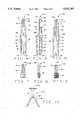
- FIG. 1is a perspective view of the safety spectacle of the present invention
- FIG. 2is an enlarged side view of one of the temple arm assemblies of the present invention
- FIG. 3is an enlarged side view of the ferrule of the temple arm assembly of FIG. 2;
- FIG. 4is an enlarged front elevational view of the attachment assembly of the temple arm assembly of FIG. 2;
- FIG. 5is an enlarged side elevational view of the attachment assembly of FIG. 4;
- FIG. 6is an enlarged rear elevational view of the attachment assembly of FIG. 4;
- FIG. 7is an enlarged rear elevational view of the lower arm plate of the temple arm assembly of FIG. 2;
- FIG. 8is an enlarged side elevational view of the lower arm plate of FIG. 7;
- FIG. 9is an enlarged front elevational view of the lower arm plate of FIG. 7;
- FIG. 10is an enlarged front elevational view of the nose bridge of the present invention.
- FIG. 11is a front elevational view of the lens of the present invention.
- FIG. 12is an enlarged front elevational view of the frame of the present invention.
- FIG. 13is an enlarged top elevational view of the frame of FIG. 12;
- FIG. 14an enlarged fragmentary side cutaway view of the frame of the present invention, showing in broken lines the attachment bracket;
- FIG. 15is a side elevational view of the earpiece of the temple arm assembly of FIG. 2.
- a safety spectacle 20is shown generally having a frame 22, a pair of temple arm assemblies 26, and a lens 28.
- the lens 28, shown in FIG. 11,comprises a unitary, one-piece, six-base curve design having integrated upper side shields 48 and lower side shields 50 separated by a rectangular shaped recess 100, the upper and lower side shields 48 and 50 and rectangular shaped recess 100 being illustrated by broken lines.
- Located centrally on the bottom of the lens 28is an arched portion 72 shaped to conform to a wearer's nose.
- the lens construction and designprovide in excess of 180 degrees coverage to the wearer.
- the lens 28is designed to meet A.N.S.I. standard Z87.1-1989 and is thus formed of a polycarbonate having a wall thickness of 0.080".
- the frame 22is shown in FIGS. 12-14.
- the frame 22generally comprises two sides 92 and a rim 102, that are formed of a plastic and preferably of a nylon.
- the rim 102has a lens receiving portion 104 defining a groove or channel on its bottom side, as outlined by broken lines in FIG. 13, and a centrally located notch 74 on its top side.
- each of the sides 92 of the frame 22includes an attachment or pivot bracket 58 defined by a projecting appendage 96 and adjacent sockets 88 positioned on outwardly extending sloped bracket arms 98.
- the attachment brackets 58are approximately the same length and width of the rectangular shaped recess 100 of the lens 28 such that the recess 100 may receive the attachment brackets 58.
- cavities 90are formed between the appendages 96 of the attachment brackets 58 and the sides 92 of the frame 22. The cavities 90 in conjunction with the appendages 96 help hold the lens 28 in place within the frame 22.
- the lens 28is inserted into the lens receiving portion 104 of the rim 102.
- the rectangular shaped recesses 100are placed over the attachment brackets 58 and inserted into the cavities 90 to fasten the lens 28 to the sides 92 of the frame 22.
- the lens 28is then secured to the rim 102 of the frame 22 by means of a T-bar nose bridge 24.
- the nose bridge 24, best seen in FIG. 10,has a clasp 82 and a nose rest 86 connected by a vertical column 84.
- the nose rest 86has a shape corresponding to that of the arched portion 72 of the lens 28 and includes a lens receiving portion or groove 106 on its top side as outlined and indicated by broken lines.
- the T-bar nose bridge 24is likewise formed of a plastic, preferably nylon.
- the lens 28is inserted into the lens receiving portion 106 of the nose rest 86, with the vertical column 84 extending up the back of the lens.
- the clasp 82is received or clamped onto the groove 74 of the rim 102.
- Each temple arm assembly 26generally comprises an earpiece 30 and an attachment assembly 34.
- the attachment assembly 34includes an upper arm plate 44 and a lower arm plate 46 extending from one end of the attachment assembly 34.
- the upper and lower arm plates 44, 46have semicircular knobs 52 and 54, respectively, centered on respective curved upper portions 68 and 80, as best shown in FIGS. 6 and 9.
- the knobs 52 and 54hinge or pivot the temple arm assemblies 26 to the sides 92 of the frame 22 by insertion into the sockets 88 of the attachment brackets 58.
- the attachment assembly 34includes a truncated cone or frusto-conical shaped earpiece receptacle 66 having a solid larger-diametered base 108 and a smaller-diametered open end 110 leading to a longitudinal internal channel 64.
- Five evenly-spaced rectangular slots or openings 40, of the same sizeare disposed along the receptacle 66 from the open end 110 to the base 108 which are in communication with the channel 64. Because of the frusto-conical shape of the receptacle, the external openings of the slots 40 are larger towards the base 108 than towards the open end 110. However, the internal dimensions of the slots 40 as they communicate with the channel 64 are the same size.
- a semicircular stem 62Extending from the base 108 of the earpiece receptacle 66 is a semicircular stem 62 of substantially equivalent diameter as the open end 110 of the earpiece receptacle 66. As best depicted in FIG. 5, the flat portion 63 of the stem 62 is positioned along the diameter of the base 108 angularly with respect to the slots 40.
- the upper arm plate 44extends from an outward projection or rim 70 on the top of the stem 26.
- a vertical convex rail 60runs across the entire longitudinal length of the backs of the upper arm plate 44 and stem 62. As described hereinbelow, the rail 60 serves as a guide or track for the lower arm plate 46.
- the earpiece 30, shown generally in FIG. 15,has a curved end 114 which is adapted to extend around the ear of the wearer, and a forked end defining a pair of prongs 94 and 116.
- the diameter of the rounded portion of the earpiece 30is approximately equal to the diameter of the channel 64 of the earpiece receptacle 66.
- Prong 94includes an essentially rectangular projecting tab 36 disposed a distance from the end thereof.
- the curved end 114 of the earpiece 30includes a slot 32 which may be connected by an elastic or other flexible material band to the other curved end 114 of the other earpiece 30 to secure the safety spectacle 20 to the head of the wearer.
- the earpiece 30is inserted into the channel 64 of the earpiece receptacle 66 and the tab 36 is locked into one of the five adjacent slots 40 on the earpiece receptacle 66.
- the prongs 94 and 116 and tab 36 of the earpiece 30 in conjunction with the slots 40 on the earpiece receptacle 66forms a quarter turn barrel configuration.
- the quarter turn barrel configurationallows the wearer to rotate the earpiece 30 ninety degrees in one direction to unlock the tab 36, then position the earpiece 30 at a desired length, and finally rotate the earpiece 30 back ninety degrees to lock the tab 36 into a different slot 40, thereby varying the length of the temple arm assembly 26.
- the lower arm plate 46 of the temple arm assembly 26is shown having a curved upper portion 80, a threaded base 78, and a vertical concave channel 76.
- the concave channel or groove 76traverses the entire longitudinal length of the back side of the lower arm plate 46.
- the threaded base 78extends only around the front and sides of the lower arm plate 46, as best depicted in FIGS. 8 and 9.
- the concave channel 76 of the lower arm plate 46conforms to the convex rail 60 of the upper arm plate 44, thereby slidably mounting the lower arm plate 46 to the upper arm plate 44.
- a ferrule 42is disposed on the arm assembly 26, specifically about the stem 62 of the upper arm plate 44 of the attachment assembly 34. Additionally, the ferrule 42 surrounds and operatively attaches the lower arm plate 46 to the upper arm plate 44 to complete the attachment assembly 34.
- the ferrule 42as depicted in FIG. 3, has an internally threaded channel 56 and is made from a plastic, preferably an acetal resin such as Delrin® and threadedly secures the stem 62 of the attachment assembly 34 to the threaded base 78 of the lower arm plate 46.
- Pantoscopic adjustmentis accomplished by repositioning the lower arm plate 46 with respect to the upper arm plate 44. This is accomplished by rotating the ferrule 42. Upon rotation of the ferrule 42, the lower arm plate 46 moves in and out of the ferrule 42 and along the convex rail 60 of the upper arm plate 44. Because the knobs 52 and 54 of the upper and lower arm plates 44 and 46 respectively, are removably fixed in the sockets 88 of the bracket 58, movement of the lower arm plate 46 relative to the upper arm plate 44 causes a tilting or angling of the arm assembly 26, thereby varying the angle of the temple arm assembly 26 between the sloped bracket arms 98 with respect to the frame 22.
- the maximum angular variationis defined by the angles of the slopes of the walls of the sloped bracket arms 98.
Landscapes
- Physics & Mathematics (AREA)
- Health & Medical Sciences (AREA)
- General Physics & Mathematics (AREA)
- Ophthalmology & Optometry (AREA)
- Optics & Photonics (AREA)
- Eyeglasses (AREA)
Abstract
Description
Claims (14)
Priority Applications (1)
| Application Number | Priority Date | Filing Date | Title |
|---|---|---|---|
| US08/504,371US5532767A (en) | 1995-07-19 | 1995-07-19 | Pantoscopic and length adjustable safety spectacle |
Applications Claiming Priority (1)
| Application Number | Priority Date | Filing Date | Title |
|---|---|---|---|
| US08/504,371US5532767A (en) | 1995-07-19 | 1995-07-19 | Pantoscopic and length adjustable safety spectacle |
Publications (1)
| Publication Number | Publication Date |
|---|---|
| US5532767Atrue US5532767A (en) | 1996-07-02 |
Family
ID=24005987
Family Applications (1)
| Application Number | Title | Priority Date | Filing Date |
|---|---|---|---|
| US08/504,371Expired - Fee RelatedUS5532767A (en) | 1995-07-19 | 1995-07-19 | Pantoscopic and length adjustable safety spectacle |
Country Status (1)
| Country | Link |
|---|---|
| US (1) | US5532767A (en) |
Cited By (27)
| Publication number | Priority date | Publication date | Assignee | Title |
|---|---|---|---|---|
| USD382293S (en)* | 1995-10-02 | 1997-08-12 | Oscar Rocco | Temple for spectacles |
| EP0878728A1 (en)* | 1997-05-17 | 1998-11-18 | Uvex Arbeitsschutz GmbH | Goggle, especially working safety glass |
| USD425926S (en)* | 1998-10-07 | 2000-05-30 | Open Sea Corporation | Protective eyewear |
| USD438886S1 (en) | 2000-03-07 | 2001-03-13 | Protective Optics, Inc. | Eyeglass components |
| USD502205S1 (en)* | 2002-09-28 | 2005-02-22 | Eston Bullard, Jr. | Adjustable eyeglass frames |
| US20080013040A1 (en)* | 2006-04-06 | 2008-01-17 | Ic! Berlin Brillen Gmbh | Eyeglass frame |
| USD565634S1 (en)* | 2005-02-19 | 2008-04-01 | Bullard Jr Eston | Adjustable eyeglass frame |
| FR2907921A1 (en)* | 2006-10-26 | 2008-05-02 | Regine Sabban | Spectacle for e.g. toddler, has lateral branches with adjustable length formed by associating main and auricular segments, where auricular segment is fixed to main segment in extension of main segment and carries two maintaining ends |
| US20080218682A1 (en)* | 2007-03-06 | 2008-09-11 | Pan-Optx, Inc. | Eyewear and methods of use |
| US20100175173A1 (en)* | 2009-01-15 | 2010-07-15 | Daniel Joseph Conrad Sutton | Eye and ear protector |
| US20130182322A1 (en)* | 2012-01-17 | 2013-07-18 | Barry David Silverstein | Stereoscopic glasses using tilted filters |
| US8756720B2 (en) | 2010-05-04 | 2014-06-24 | Honeywell International Inc | Multiple lens geometries for safety glasses |
| US9164293B2 (en) | 2011-10-24 | 2015-10-20 | Dolby Laboratories Licensing Corporation | Adjustable eyewear with fixed temple and method of manufacture |
| USD747401S1 (en)* | 2014-10-10 | 2016-01-12 | Ontel Products Corporation | Eyewear |
| USD847897S1 (en)* | 2018-09-25 | 2019-05-07 | Oakley, Inc. | Eyeglasses |
| USD855096S1 (en)* | 2013-01-25 | 2019-07-30 | 100% Speedlab, Llc | Sunglasses |
| USD855686S1 (en)* | 2017-05-01 | 2019-08-06 | Oakley, Inc. | Eyeglass component |
| USD860301S1 (en)* | 2017-07-19 | 2019-09-17 | Lenovo (Beijing) Co., Ltd. | Smart glasses |
| USD868878S1 (en)* | 2017-10-13 | 2019-12-03 | Smith Optics, Inc. | Goggle |
| US10948746B2 (en) | 2017-10-13 | 2021-03-16 | Smith Sport Optics, Inc. | Goggle with replaceable lens |
| USD914795S1 (en) | 2019-06-24 | 2021-03-30 | 100% Speedlab, Llc | Sunglasses |
| USD925646S1 (en) | 2019-05-24 | 2021-07-20 | 100% Speedlab, Llc | Sunglasses |
| US11206880B1 (en)* | 2020-07-17 | 2021-12-28 | Pegasos One, LLC | Face shield for personal protection |
| US11726351B2 (en) | 2018-11-05 | 2023-08-15 | Smith Sport Optics, Inc. | Goggle lens with compound curvature for downward field of view enhancement |
| CN117572661A (en)* | 2024-01-02 | 2024-02-20 | 浙江方氏眼镜制造有限公司 | A glasses hinge structure and adjustment method with adjustable tightness |
| BE1030847B1 (en)* | 2022-09-07 | 2024-04-02 | Vanessa Wils | Adjustable assembly arms for glasses and adjustable glasses with arms assembly |
| US20250060599A1 (en)* | 2023-08-17 | 2025-02-20 | Apple Inc. | Adjustable securement arm |
Citations (12)
| Publication number | Priority date | Publication date | Assignee | Title |
|---|---|---|---|---|
| US1252126A (en)* | 1917-03-16 | 1918-01-01 | Louis Letzeisen | Spectacles. |
| US2080503A (en)* | 1936-07-15 | 1937-05-18 | Lowres Optical Mfg Co | Ophthalmic mounting |
| US3189912A (en)* | 1961-03-10 | 1965-06-15 | Crawford Maddox | Adjustable temple members for spectacles and method of assembly |
| US3271094A (en)* | 1961-11-28 | 1966-09-06 | Wallace P Wildermuth | Adjustable eyeglass temple unit |
| US3667834A (en)* | 1971-03-22 | 1972-06-06 | Mine Safety Appliances Co | Adjustable length temple for spectacles |
| US4071165A (en)* | 1975-12-29 | 1978-01-31 | Norbert Leopoldi | Paper dispenser having a frictional discharge assistant |
| US4527291A (en)* | 1983-02-01 | 1985-07-09 | Uvex Winter Optik Gmbh | Safety goggles, in particular for work use |
| US4544245A (en)* | 1979-07-16 | 1985-10-01 | Mckesson Corporation | Adjustable safety spectacle |
| US4792221A (en)* | 1988-01-25 | 1988-12-20 | John R. Gregory | Vertical plane adjusting mechanism for eyeglasses |
| US5016292A (en)* | 1989-12-07 | 1991-05-21 | Mark Rademacher | Combination gamma, ultraviolet and X-radiation goggles |
| US5289592A (en)* | 1992-04-03 | 1994-03-01 | Paivarinta Reijo J | Eye glass holder |
| US5381192A (en)* | 1991-08-07 | 1995-01-10 | Uvex Safety, Llc | Protective eyeglasses construction with adjustable temples |
- 1995
- 1995-07-19USUS08/504,371patent/US5532767A/ennot_activeExpired - Fee Related
Patent Citations (12)
| Publication number | Priority date | Publication date | Assignee | Title |
|---|---|---|---|---|
| US1252126A (en)* | 1917-03-16 | 1918-01-01 | Louis Letzeisen | Spectacles. |
| US2080503A (en)* | 1936-07-15 | 1937-05-18 | Lowres Optical Mfg Co | Ophthalmic mounting |
| US3189912A (en)* | 1961-03-10 | 1965-06-15 | Crawford Maddox | Adjustable temple members for spectacles and method of assembly |
| US3271094A (en)* | 1961-11-28 | 1966-09-06 | Wallace P Wildermuth | Adjustable eyeglass temple unit |
| US3667834A (en)* | 1971-03-22 | 1972-06-06 | Mine Safety Appliances Co | Adjustable length temple for spectacles |
| US4071165A (en)* | 1975-12-29 | 1978-01-31 | Norbert Leopoldi | Paper dispenser having a frictional discharge assistant |
| US4544245A (en)* | 1979-07-16 | 1985-10-01 | Mckesson Corporation | Adjustable safety spectacle |
| US4527291A (en)* | 1983-02-01 | 1985-07-09 | Uvex Winter Optik Gmbh | Safety goggles, in particular for work use |
| US4792221A (en)* | 1988-01-25 | 1988-12-20 | John R. Gregory | Vertical plane adjusting mechanism for eyeglasses |
| US5016292A (en)* | 1989-12-07 | 1991-05-21 | Mark Rademacher | Combination gamma, ultraviolet and X-radiation goggles |
| US5381192A (en)* | 1991-08-07 | 1995-01-10 | Uvex Safety, Llc | Protective eyeglasses construction with adjustable temples |
| US5289592A (en)* | 1992-04-03 | 1994-03-01 | Paivarinta Reijo J | Eye glass holder |
Cited By (32)
| Publication number | Priority date | Publication date | Assignee | Title |
|---|---|---|---|---|
| USD382293S (en)* | 1995-10-02 | 1997-08-12 | Oscar Rocco | Temple for spectacles |
| EP0878728A1 (en)* | 1997-05-17 | 1998-11-18 | Uvex Arbeitsschutz GmbH | Goggle, especially working safety glass |
| USD425926S (en)* | 1998-10-07 | 2000-05-30 | Open Sea Corporation | Protective eyewear |
| USD438886S1 (en) | 2000-03-07 | 2001-03-13 | Protective Optics, Inc. | Eyeglass components |
| USD502205S1 (en)* | 2002-09-28 | 2005-02-22 | Eston Bullard, Jr. | Adjustable eyeglass frames |
| USD565634S1 (en)* | 2005-02-19 | 2008-04-01 | Bullard Jr Eston | Adjustable eyeglass frame |
| US20080013040A1 (en)* | 2006-04-06 | 2008-01-17 | Ic! Berlin Brillen Gmbh | Eyeglass frame |
| FR2907921A1 (en)* | 2006-10-26 | 2008-05-02 | Regine Sabban | Spectacle for e.g. toddler, has lateral branches with adjustable length formed by associating main and auricular segments, where auricular segment is fixed to main segment in extension of main segment and carries two maintaining ends |
| US20080218682A1 (en)* | 2007-03-06 | 2008-09-11 | Pan-Optx, Inc. | Eyewear and methods of use |
| US7520606B2 (en) | 2007-03-06 | 2009-04-21 | Pan-Optx, Inc. | Eyewear and methods of use |
| US20100175173A1 (en)* | 2009-01-15 | 2010-07-15 | Daniel Joseph Conrad Sutton | Eye and ear protector |
| US7921468B2 (en)* | 2009-01-15 | 2011-04-12 | Daniel Joseph Conrad Sutton | Eye and ear protector |
| US8756720B2 (en) | 2010-05-04 | 2014-06-24 | Honeywell International Inc | Multiple lens geometries for safety glasses |
| US9164293B2 (en) | 2011-10-24 | 2015-10-20 | Dolby Laboratories Licensing Corporation | Adjustable eyewear with fixed temple and method of manufacture |
| US20130182322A1 (en)* | 2012-01-17 | 2013-07-18 | Barry David Silverstein | Stereoscopic glasses using tilted filters |
| US10768449B2 (en)* | 2012-01-17 | 2020-09-08 | Imax Theatres International Limited | Stereoscopic glasses using tilted filters |
| USD855096S1 (en)* | 2013-01-25 | 2019-07-30 | 100% Speedlab, Llc | Sunglasses |
| USD870789S1 (en)* | 2013-01-25 | 2019-12-24 | 100% Speedlab, Llc | Sunglasses |
| USD747401S1 (en)* | 2014-10-10 | 2016-01-12 | Ontel Products Corporation | Eyewear |
| USD855686S1 (en)* | 2017-05-01 | 2019-08-06 | Oakley, Inc. | Eyeglass component |
| USD873330S1 (en)* | 2017-07-19 | 2020-01-21 | Lenovo (Beijing) Co., Ltd. | Smart glasses |
| USD860301S1 (en)* | 2017-07-19 | 2019-09-17 | Lenovo (Beijing) Co., Ltd. | Smart glasses |
| US10948746B2 (en) | 2017-10-13 | 2021-03-16 | Smith Sport Optics, Inc. | Goggle with replaceable lens |
| USD868878S1 (en)* | 2017-10-13 | 2019-12-03 | Smith Optics, Inc. | Goggle |
| USD847897S1 (en)* | 2018-09-25 | 2019-05-07 | Oakley, Inc. | Eyeglasses |
| US11726351B2 (en) | 2018-11-05 | 2023-08-15 | Smith Sport Optics, Inc. | Goggle lens with compound curvature for downward field of view enhancement |
| USD925646S1 (en) | 2019-05-24 | 2021-07-20 | 100% Speedlab, Llc | Sunglasses |
| USD914795S1 (en) | 2019-06-24 | 2021-03-30 | 100% Speedlab, Llc | Sunglasses |
| US11206880B1 (en)* | 2020-07-17 | 2021-12-28 | Pegasos One, LLC | Face shield for personal protection |
| BE1030847B1 (en)* | 2022-09-07 | 2024-04-02 | Vanessa Wils | Adjustable assembly arms for glasses and adjustable glasses with arms assembly |
| US20250060599A1 (en)* | 2023-08-17 | 2025-02-20 | Apple Inc. | Adjustable securement arm |
| CN117572661A (en)* | 2024-01-02 | 2024-02-20 | 浙江方氏眼镜制造有限公司 | A glasses hinge structure and adjustment method with adjustable tightness |
Similar Documents
| Publication | Publication Date | Title |
|---|---|---|
| US5532767A (en) | Pantoscopic and length adjustable safety spectacle | |
| US9122078B2 (en) | Releasable earstem mounting mechanism for eyewear | |
| US5768716A (en) | Goggles, in particular for sports and/or leisure wear | |
| US7246901B2 (en) | Adjustable length upper frame member for eyeglasses | |
| US5528320A (en) | Protective eyewear | |
| AU749428B2 (en) | Ventilated browbar frame and eyewear | |
| CA2181020A1 (en) | Eyeglass construction | |
| GB2227157A (en) | Eye & hearing protection unit | |
| US4544245A (en) | Adjustable safety spectacle | |
| US5291230A (en) | Ophthalmic device includes a detachable nosepiece | |
| US4844605A (en) | Auxiliary earpiece for use with eyeglasses | |
| US5539561A (en) | Eyeglass having removable temple/lens connector | |
| HK95396A (en) | Spectacles with nose pad | |
| US4799782A (en) | Adjustable eye glass frame | |
| US6786594B1 (en) | Hinge for eyewear | |
| JPH05504849A (en) | glasses | |
| US7407282B1 (en) | Eyeglass temple assembly | |
| KR102356437B1 (en) | Clip-Typed Goggles Fixing Unit with Golf Ball Marker Holder | |
| EP0389443A2 (en) | Eyeglasses with integral rear view mirror | |
| KR20230019580A (en) | Combination structure of spectacle frame and spectacle leg | |
| US6834954B2 (en) | Spectacles of the type without a surround | |
| JP2007047283A (en) | Temple for glasses | |
| GB2594583A (en) | A modified spectacle temple | |
| KR200374024Y1 (en) | Safety cap having multi-function | |
| US6974213B1 (en) | Monoblock assembly for eyewear |
Legal Events
| Date | Code | Title | Description |
|---|---|---|---|
| AS | Assignment | Owner name:JACKSON PRODUCTS, INC., MICHIGAN Free format text:ASSIGNMENT OF ASSIGNORS INTEREST;ASSIGNORS:PLEUNE, DANIEL A.;ROE, WILLIAM E.;REEL/FRAME:007599/0004 Effective date:19950714 | |
| AS | Assignment | Owner name:HELLER FINANCIAL, INC., A DELAWARE CORPORATION, IL Free format text:SECOND SUPPLEMENTAL PATENT SECURITY AGREEMENT;ASSIGNOR:JACKSON PRODUCTS, INC., A DELAWARE CORPORATION, (FORMERLY JACKSON ACQUISITION COMPANY);REEL/FRAME:008503/0899 Effective date:19961021 | |
| AS | Assignment | Owner name:BANKBOSTON, N.A., AS AGENT, MASSACHUSETTS Free format text:PATENT COLLATERAL ASSIGNMENT AND SECURITY AGREEMENT;ASSIGNOR:JACKSON PRODUCTS, INC.;REEL/FRAME:009214/0821 Effective date:19980422 | |
| REMI | Maintenance fee reminder mailed | ||
| LAPS | Lapse for failure to pay maintenance fees | ||
| FP | Lapsed due to failure to pay maintenance fee | Effective date:20000702 | |
| AS | Assignment | Owner name:JPCA, INC., TEXAS Free format text:PATENT COLLATERAL ASSIGNMENT AND SECURITY AGREEMENT;ASSIGNOR:JACKSON PRODUCTS, INC.;REEL/FRAME:012841/0115 Effective date:20020410 | |
| STCH | Information on status: patent discontinuation | Free format text:PATENT EXPIRED DUE TO NONPAYMENT OF MAINTENANCE FEES UNDER 37 CFR 1.362 |