US5532703A - Antenna coupler for portable cellular telephones - Google Patents
Antenna coupler for portable cellular telephonesDownload PDFInfo
- Publication number
- US5532703A US5532703AUS08/344,546US34454694AUS5532703AUS 5532703 AUS5532703 AUS 5532703AUS 34454694 AUS34454694 AUS 34454694AUS 5532703 AUS5532703 AUS 5532703A
- Authority
- US
- United States
- Prior art keywords
- antenna
- coupler
- sections
- coaxial cable
- conductor
- Prior art date
- Legal status (The legal status is an assumption and is not a legal conclusion. Google has not performed a legal analysis and makes no representation as to the accuracy of the status listed.)
- Expired - Fee Related
Links
- 230000001413cellular effectEffects0.000titleclaimsabstractdescription16
- 239000004020conductorSubstances0.000claimsabstractdescription30
- 230000013011matingEffects0.000claimsabstractdescription9
- 239000004033plasticSubstances0.000claimsabstractdescription9
- 229920003023plasticPolymers0.000claimsabstractdescription9
- 230000001939inductive effectEffects0.000claimsabstractdescription6
- 239000000463materialSubstances0.000claimsabstractdescription6
- 239000002184metalSubstances0.000claimsdescription7
- 230000008878couplingEffects0.000description3
- 238000010168coupling processMethods0.000description3
- 238000005859coupling reactionMethods0.000description3
- 229910001369BrassInorganic materials0.000description2
- 239000000853adhesiveSubstances0.000description2
- 230000001070adhesive effectEffects0.000description2
- 230000005540biological transmissionEffects0.000description2
- 239000010951brassSubstances0.000description2
- 229910001220stainless steelInorganic materials0.000description2
- 239000010935stainless steelSubstances0.000description2
- 241000272525Anas platyrhynchosSpecies0.000description1
- 239000011324beadSubstances0.000description1
- 230000015556catabolic processEffects0.000description1
- 239000004568cementSubstances0.000description1
- 239000011248coating agentSubstances0.000description1
- 238000000576coating methodMethods0.000description1
- 238000006731degradation reactionMethods0.000description1
- 239000012772electrical insulation materialSubstances0.000description1
- 239000011521glassSubstances0.000description1
- 238000009413insulationMethods0.000description1
- 239000002991molded plasticSubstances0.000description1
- 230000000717retained effectEffects0.000description1
- 229910000679solderInorganic materials0.000description1
Images

Classifications
- H—ELECTRICITY
- H01—ELECTRIC ELEMENTS
- H01Q—ANTENNAS, i.e. RADIO AERIALS
- H01Q1/00—Details of, or arrangements associated with, antennas
- H01Q1/12—Supports; Mounting means
- H01Q1/22—Supports; Mounting means by structural association with other equipment or articles
- H01Q1/24—Supports; Mounting means by structural association with other equipment or articles with receiving set
- H01Q1/241—Supports; Mounting means by structural association with other equipment or articles with receiving set used in mobile communications, e.g. GSM
- H01Q1/242—Supports; Mounting means by structural association with other equipment or articles with receiving set used in mobile communications, e.g. GSM specially adapted for hand-held use
Definitions
- a portable cellular telephoneWhen a portable cellular telephone is used within a motor vehicle, the user frequently experiences a decrease in performance of the telephone reception and transmission due to the fact that the built-in antenna on the telephone is partially shielded by the metal body of the vehicle.
- Some portable cellular telephoneshave a female jack for receiving a plug on a coaxial cable connected to an external antenna.
- many portable telephonesdo not have such a jack and incorporate retractable, whip-like or flexible wire antennas which usually have a length of about 4 to 4.5 inches and a diameter between 0.075 and 0.095 inch. Such antennas are retractable into the housing of the telephone and are extended when it is desired to use the telephone.
- the present inventionis directed to an improved antenna coupler which is ideally suited for use with retractable wire-type antennas on portable telephones or transceivers and which is convenient and easy to use for releasably coupling a coaxial cable extending from a remote external antenna to the retractable antenna on the telephone or transceiver.
- the coupler of the inventionis especially easy to attach to an extended retractable antenna while the telephone or transceiver is within a motor vehicle and to release from the retractable antenna when it is desired to remove the telephone or transceiver from the vehicle.
- the coupler of the inventionfurther provides for obtaining an effective and efficient inductive connection between the center conductor of the coaxial cable and the retractable antenna.
- an elongated coupler bodyis formed by two mating longitudinal sections which are molded of a rigid plastics material.
- the sectionsinclude longitudinally spaced hook-shaped tabs which project laterally from the sections in opposite directions to provide for quickly and positively clipping the coupler body to the retractable wire antenna by slightly flexing the antenna to snap the antenna behind the tabs.
- the body sectionsalso define therebetween a longitudinally extending internal cavity for receiving and retaining a coaxial cable conductor or a flat metal extension of the conductor having a length of approximately three inches or one-quarter wave length of the telephone frequency range.
- the body sectionsalso clamp a straight or inverted J-shaped portion of the coaxial cable to provide a strain relief and to position the cable conveniently adjacent the housing of the portable telephone.
- FIG. 1is a perspective view of an antenna coupler constructed in accordance with the invention and showing its attachment to an extruded retractable cellular telephone antenna for coupling the antenna to a remote external antenna.
- FIG. 2is an enlarged perspective view of the coupler shown in FIG. 1 and shown exploded from the retractable antenna of the telephone;
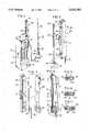
- FIG. 3is an exploded perspective view of the components for the coupler shown in FIGS. 1 and 2;
- FIG. 4is a fragmentary section of the coupler, taken generally on a line 4--4 of FIG. 2;
- FIGS. 5-7are fragmentary sections taken generally on the lines 5--5, 6--6 and 7--7 of FIG. 4.
- FIG. 8is a view similar to FIG. 3 and showing a modified coupler constructed in accordance with another embodiment of the invention.
- FIG. 9is a view similar to FIG. 4 of the embodiment shown in FIG. 8.
- FIG. 1illustrates a transceiver in the form of a conventional portable cellular telephone 10 which includes a housing 12 defining openings for an earpiece 13 and a microphone 14 and a push button keyboard 16.
- the telephone 10also includes a retractable flexible antenna 20 which is shown in its extended position in FIGS. 1 and 2.
- the antenna 20consists of a flexible stainless steel spring wire surrounded by a coating or layer of electrical insulation material 22 so that the antenna may be flexed through 90° and, when released, springs back or returns to its straight position shown in FIGS. 1 and 2.
- a cap 23is secured to the outer end portion of the wire antenna 20 and engages a collar 24 when the antenna is pushed inwardly to its retracted position within the housing 12.
- a coupler device or coupler 30transmits radio frequency or RF signals between the antenna 20 and a coaxial cable 32 which extends from the base 34 of a remote external antenna 35.
- the antenna 35is of a conventional type and includes a flexible stainless steel spring wire element 38 with an integral phasing coil 39. The coil is attached by a threaded fitting 41 to the base 34 which encloses a flat magnet adjacent its bottom surface.
- the cable 32may have a length of many feet, and the base 34 is usually attached temporarily to the metal roof of a motor vehicle during use of the vehicle.
- the coaxial cable 32may al so extend from a window clip-on antenna or the inside coupler box for a glass mounted antenna, both of which are commonly used on motor vehicles as external antennas for cellular telephones.
- the elongated coupler 30includes a body formed by two longitudinally extending and mating half sections 46 and 48 each of which is molded of a rigid plastics material.
- the body section 46is molded with an integrally projecting hook-shaped tab 51 which projects laterally between two longitudinally spaced hooked-shaped tabs 52 and 53 molded as an integral part of the body section 48 and projecting laterally in the opposite direction.
- the section 46also includes a longitudinally extending recess or cavity 56 which is parallel and adjacent a flat edge surface 57.
- the cavity 56receives a linear portion 61 of a twisted center wire metal conductor of the coaxial cable 32.
- the twisted wire conductor portion 61has a length of about three inches which is approximately one-quarter wave length of the frequency range used for cellular telephone transmission.
- the linear conductor portion 61includes a tubular insulating sleeve of plastics material, and this insulating sleeve or layer is surrounded within the cable 32 by a braided metal wire shield which is surrounded by an outer sleeve or layer of plastics material.
- An S-shaped cavity 64is formed within the base portion of the body section 46, and an inverted J-shaped cavity 66 is formed within the base portion of the body section 48, as shown in FIG. 3.
- the center conductorhas an S-shaped portion 67 which extends into the cavities 64 and 66 to form a strain relief for the cable 32, as shown in FIG. 4.
- the mating sections 46 and 48 of the coupler 30are cemented or ultrasonically welded together. After the body sections are attached together, the cable 32 and conductor portions 61 and 67 are secured within the corresponding cavities.
- the abutting surfaces of the body sections 46 and 48may be provided with longitudinally spaced cylindrical pins and corresponding tight-fitting holes (not shown) for quickly and precisely aligning and retaining the body sections together during curing of the adhesive.
- the coupleris easily attached to the extended retractable antenna 20 by simply hooking the lower tab 52 onto the antenna and then manually flexing the antenna slightly to locate the antenna within the tabs 51 and 53, as shown in FIGS. 1 and 4.
- the coupler 30is clipped onto the antenna 20 in this manner, the coupler is positively retained on the antenna 20 and also prevents or blocks the antenna from being accidentally pushed inwardly towards its retracted position.
- the coaxial cable 32projects from one end of the body sections and downwardly along the side of the housing 12. Thus the cable may be enclosed within a hand gripping the telephone 10 to prevent the cable from accidentally hooking onto an object.
- the coupler 30may also be quickly removed from the antenna 20 simply by gripping the outer cap 23 of the antenna and flexing the outer end portion of the antenna 20 from behind the tab 53. The coupler 30 may then be rotated slightly to remove the antenna 20 from the tabs 51 and 52.
- a coupler device 80is constructed very similar to the coupler device 30 and includes mating elongated plastic body sections 82 and 84 which have corresponding outwardly projecting hook-shaped tabs 86,87 and 88.
- a thin flat metal conductor or brass strip 91is connected or attached to the wire conductor 61 by the solder connection 93.
- the flat brass conductor 91seats within an elongated recess or cavity 96 within the body section 82, and the soldered connection 93 is located within mating cavities 98 within the body sections.
- a set of three pins or studs 102are molded as an integral part of the body section 84 and project through corresponding holes 103 within the flat conductor 91 and into corresponding blind holes 106 within the body section 82 to locate the conductor 91 as it is sandwiched between the body sections 82 and 84 and to position the body sections with respect to each other.
- a pair of mating cavities 108are molded within the bottom portions of the body sections 82 and 84, and each cavity has a set of longitudinally spaced ribs 109 which engage or grip the resilient insulation on the coaxial cable 32 and form a strain relief or positive connection between the cable 32 and coupler device 80 when the body sections 82 and 84 are assembled for clamping the cable 32 within the cavities 108 and for clamping the strip conductor 91 between the body sections.
- a bead 111 of contact cement or adhesiveis extruded onto the body section 82 for securing the body sections 82 and 84 together after assembly.
- the coupler device 80also includes a nut 113 which is molded as an integral part of the tab 88 and has an internally threaded hole for receiving a molded plastic screw 115 which carries a resilient O-ring 117. As shown in FIG. 9, when the screw 115 is threaded through the nut 113, the pointed tip of the screw 115 presses the antenna 20 against the tab 88 and thereby holds the coupler device 80 on the antenna so that the coupler device does not shift or slide longitudinally on the antenna.
- an antenna coupler constructed in accordance with the present inventionprovides a number of desirable features.
- the coupler 30 or 80may be quickly and easily attached by one hand to an extended antenna 20 and may also be quickly and easily released from the antenna.
- the conductor 61 or 91By also locating the linear conductor 61 or 91 in close parallel relation or close proximity to the antenna 20, that is, within about 0.125 inch, the conductor 61 or 91 provides an effective inductive pick up or connection between the antenna 20 and the coaxial cable 32 so that very little signal is lost.
- the coupler 30 or 80also provides for directing the coaxial cable 32 from the coupler adjacent the side of the telephone housing 12 so that the cable 32 does not interfere with convenient use of the telephone 10.
- the screw 115prevents the coupler from sliding on the antenna 20.
Landscapes
- Engineering & Computer Science (AREA)
- Computer Networks & Wireless Communication (AREA)
- Details Of Aerials (AREA)
- Support Of Aerials (AREA)
Abstract
Description
Claims (9)
Priority Applications (1)
| Application Number | Priority Date | Filing Date | Title |
|---|---|---|---|
| US08/344,546US5532703A (en) | 1993-04-22 | 1994-11-23 | Antenna coupler for portable cellular telephones |
Applications Claiming Priority (2)
| Application Number | Priority Date | Filing Date | Title |
|---|---|---|---|
| US5058893A | 1993-04-22 | 1993-04-22 | |
| US08/344,546US5532703A (en) | 1993-04-22 | 1994-11-23 | Antenna coupler for portable cellular telephones |
Related Parent Applications (1)
| Application Number | Title | Priority Date | Filing Date |
|---|---|---|---|
| US5058893AContinuation-In-Part | 1993-04-22 | 1993-04-22 |
Publications (1)
| Publication Number | Publication Date |
|---|---|
| US5532703Atrue US5532703A (en) | 1996-07-02 |
Family
ID=21966136
Family Applications (1)
| Application Number | Title | Priority Date | Filing Date |
|---|---|---|---|
| US08/344,546Expired - Fee RelatedUS5532703A (en) | 1993-04-22 | 1994-11-23 | Antenna coupler for portable cellular telephones |
Country Status (1)
| Country | Link |
|---|---|
| US (1) | US5532703A (en) |
Cited By (63)
| Publication number | Priority date | Publication date | Assignee | Title |
|---|---|---|---|---|
| US5777585A (en)* | 1995-04-08 | 1998-07-07 | Sony Corporation | Antenna coupling apparatus, external-antenna connecting apparatus, and onboard external-antenna connecting apparatus |
| US5854970A (en)* | 1996-10-08 | 1998-12-29 | Nokia Mobile Phones Limited | Accessory RF unit for hand-held wireless telephone systems |
| US5920293A (en)* | 1997-08-01 | 1999-07-06 | Motorola, Inc. | Radio frequency (RF) antenna coupler with an electrically extended ground plane |
| US5940038A (en)* | 1994-12-15 | 1999-08-17 | Nokia Mobile Phones Limited | Radio telephone |
| US5963871A (en)* | 1996-10-04 | 1999-10-05 | Telefonaktiebolaget Lm Ericsson | Retractable multi-band antennas |
| EP0955549A1 (en)* | 1998-05-05 | 1999-11-10 | Adeunis R.F. | Apparatus for radiofrequency measurements on an industrial test bench |
| US6112102A (en)* | 1996-10-04 | 2000-08-29 | Telefonaktiebolaget Lm Ericsson | Multi-band non-uniform helical antennas |
| US6157819A (en)* | 1996-05-14 | 2000-12-05 | Lk-Products Oy | Coupling element for realizing electromagnetic coupling and apparatus for coupling a radio telephone to an external antenna |
| US6163711A (en)* | 1997-12-01 | 2000-12-19 | Nokia Mobile Phones, Ltd | Method and apparatus for interfacing a mobile phone with an existing audio system |
| US6166694A (en)* | 1998-07-09 | 2000-12-26 | Telefonaktiebolaget Lm Ericsson (Publ) | Printed twin spiral dual band antenna |
| GB2353412A (en)* | 1999-08-11 | 2001-02-21 | Motorola Israel Ltd | Inductively coupling radiation from an antenna |
| US6317089B1 (en) | 1999-12-23 | 2001-11-13 | Wilson Electronics, Inc. | Hand-held transceiver antenna system |
| US6329962B2 (en) | 1998-08-04 | 2001-12-11 | Telefonaktiebolaget Lm Ericsson (Publ) | Multiple band, multiple branch antenna for mobile phone |
| GB2324657B (en)* | 1997-04-26 | 2002-01-23 | Rohde & Schwarz | Aerial coupler for mobile telephones |
| US6343208B1 (en) | 1998-12-16 | 2002-01-29 | Telefonaktiebolaget Lm Ericsson (Publ) | Printed multi-band patch antenna |
| US6353443B1 (en)* | 1998-07-09 | 2002-03-05 | Telefonaktiebolaget Lm Ericsson (Publ) | Miniature printed spiral antenna for mobile terminals |
| US20040038644A1 (en)* | 2002-08-22 | 2004-02-26 | Eagle Broadband, Inc. | Repeater for a satellite phone |
| US20050068250A1 (en)* | 2003-09-25 | 2005-03-31 | Alcatel | Apparatus and method for clamping cables in an antenna |
| US6885845B1 (en)* | 1993-04-05 | 2005-04-26 | Ambit Corp. | Personal communication device connectivity arrangement |
| US20060077103A1 (en)* | 2004-10-12 | 2006-04-13 | Hayes Gerard J | Supplemental parasitic antenna apparatus |
| US7405702B2 (en)* | 2003-07-24 | 2008-07-29 | Pulse Finland Oy | Antenna arrangement for connecting an external device to a radio device |
| US20080266198A1 (en)* | 2007-04-30 | 2008-10-30 | Walker Paul N | Antenna grounding system and method |
| US20110199271A1 (en)* | 2008-10-30 | 2011-08-18 | Rohde & Schwarz Gmbh & Co. Kg | Portable dual-band antenna |
| US8248314B2 (en) | 2010-09-22 | 2012-08-21 | Ash Jr Daniel R | Inductively coupled signal booster for a wireless communication device and in combination therewith |
| US8466756B2 (en) | 2007-04-19 | 2013-06-18 | Pulse Finland Oy | Methods and apparatus for matching an antenna |
| US8473017B2 (en) | 2005-10-14 | 2013-06-25 | Pulse Finland Oy | Adjustable antenna and methods |
| US8564485B2 (en) | 2005-07-25 | 2013-10-22 | Pulse Finland Oy | Adjustable multiband antenna and methods |
| US20130292396A1 (en)* | 2012-05-03 | 2013-11-07 | Apple Inc. | Crack Resistant Plastic Enclosure Structures |
| US8618990B2 (en) | 2011-04-13 | 2013-12-31 | Pulse Finland Oy | Wideband antenna and methods |
| US8629813B2 (en) | 2007-08-30 | 2014-01-14 | Pusle Finland Oy | Adjustable multi-band antenna and methods |
| US8648752B2 (en) | 2011-02-11 | 2014-02-11 | Pulse Finland Oy | Chassis-excited antenna apparatus and methods |
| US8786499B2 (en) | 2005-10-03 | 2014-07-22 | Pulse Finland Oy | Multiband antenna system and methods |
| US8847833B2 (en) | 2009-12-29 | 2014-09-30 | Pulse Finland Oy | Loop resonator apparatus and methods for enhanced field control |
| US8866689B2 (en) | 2011-07-07 | 2014-10-21 | Pulse Finland Oy | Multi-band antenna and methods for long term evolution wireless system |
| JP2015015598A (en)* | 2013-07-04 | 2015-01-22 | ツインバード工業株式会社 | Electronic apparatus |
| US8988296B2 (en) | 2012-04-04 | 2015-03-24 | Pulse Finland Oy | Compact polarized antenna and methods |
| US9124679B2 (en) | 2010-09-22 | 2015-09-01 | Mojoose, Inc. | Sleeve with electronic extensions for a cell phone |
| US9123990B2 (en) | 2011-10-07 | 2015-09-01 | Pulse Finland Oy | Multi-feed antenna apparatus and methods |
| US9203154B2 (en) | 2011-01-25 | 2015-12-01 | Pulse Finland Oy | Multi-resonance antenna, antenna module, radio device and methods |
| US9246210B2 (en) | 2010-02-18 | 2016-01-26 | Pulse Finland Oy | Antenna with cover radiator and methods |
| US9350081B2 (en) | 2014-01-14 | 2016-05-24 | Pulse Finland Oy | Switchable multi-radiator high band antenna apparatus |
| US9406998B2 (en) | 2010-04-21 | 2016-08-02 | Pulse Finland Oy | Distributed multiband antenna and methods |
| US9450291B2 (en) | 2011-07-25 | 2016-09-20 | Pulse Finland Oy | Multiband slot loop antenna apparatus and methods |
| US9461371B2 (en) | 2009-11-27 | 2016-10-04 | Pulse Finland Oy | MIMO antenna and methods |
| US9484619B2 (en) | 2011-12-21 | 2016-11-01 | Pulse Finland Oy | Switchable diversity antenna apparatus and methods |
| JP2016220147A (en)* | 2015-05-25 | 2016-12-22 | タイコエレクトロニクスジャパン合同会社 | antenna |
| US9531058B2 (en) | 2011-12-20 | 2016-12-27 | Pulse Finland Oy | Loosely-coupled radio antenna apparatus and methods |
| US9590308B2 (en) | 2013-12-03 | 2017-03-07 | Pulse Electronics, Inc. | Reduced surface area antenna apparatus and mobile communications devices incorporating the same |
| US9634383B2 (en) | 2013-06-26 | 2017-04-25 | Pulse Finland Oy | Galvanically separated non-interacting antenna sector apparatus and methods |
| US9647338B2 (en) | 2013-03-11 | 2017-05-09 | Pulse Finland Oy | Coupled antenna structure and methods |
| US9673507B2 (en) | 2011-02-11 | 2017-06-06 | Pulse Finland Oy | Chassis-excited antenna apparatus and methods |
| US9680212B2 (en) | 2013-11-20 | 2017-06-13 | Pulse Finland Oy | Capacitive grounding methods and apparatus for mobile devices |
| WO2017127845A1 (en)* | 2016-01-21 | 2017-07-27 | Marcio Marc Abreu | Antenna configuration for mobile communication device |
| US9722308B2 (en) | 2014-08-28 | 2017-08-01 | Pulse Finland Oy | Low passive intermodulation distributed antenna system for multiple-input multiple-output systems and methods of use |
| US9761951B2 (en) | 2009-11-03 | 2017-09-12 | Pulse Finland Oy | Adjustable antenna apparatus and methods |
| US9906260B2 (en) | 2015-07-30 | 2018-02-27 | Pulse Finland Oy | Sensor-based closed loop antenna swapping apparatus and methods |
| US9948002B2 (en) | 2014-08-26 | 2018-04-17 | Pulse Finland Oy | Antenna apparatus with an integrated proximity sensor and methods |
| US9973228B2 (en) | 2014-08-26 | 2018-05-15 | Pulse Finland Oy | Antenna apparatus with an integrated proximity sensor and methods |
| US9979078B2 (en) | 2012-10-25 | 2018-05-22 | Pulse Finland Oy | Modular cell antenna apparatus and methods |
| US10069209B2 (en) | 2012-11-06 | 2018-09-04 | Pulse Finland Oy | Capacitively coupled antenna apparatus and methods |
| US10079428B2 (en) | 2013-03-11 | 2018-09-18 | Pulse Finland Oy | Coupled antenna structure and methods |
| US11057130B2 (en) | 2017-01-02 | 2021-07-06 | Mojoose, Inc. | Automatic signal strength indicator and automatic antenna switch |
| US20250212350A1 (en)* | 2023-12-26 | 2025-06-26 | Mabuchi Motor Co., Ltd. | Lead holding portion structure and motor |
Citations (12)
| Publication number | Priority date | Publication date | Assignee | Title |
|---|---|---|---|---|
| US2790899A (en)* | 1955-06-08 | 1957-04-30 | Stromberg Carlson Co | Antenna system which supplements that of portable radio inside automobile |
| US3364487A (en)* | 1964-12-01 | 1968-01-16 | Rosario J. Maheux | Portable radio receiver antenna coupler set |
| US3518681A (en)* | 1965-04-06 | 1970-06-30 | Paul Edwin Kiepe | Back-country radio booster |
| US3636912A (en)* | 1970-05-06 | 1972-01-25 | Leonard F Kamp | Device for attachment to an elongated support extending from a vehicle |
| US3826935A (en)* | 1972-09-12 | 1974-07-30 | Whirlpool Co | Motor housing construction for a vacuum cleaner with strain-relief for motor leads |
| US4167738A (en)* | 1977-06-27 | 1979-09-11 | Dennis Kirkendall | Antenna mounted tuning indicator |
| US4193076A (en)* | 1977-04-26 | 1980-03-11 | Sansui Electric Co. Ltd. | Coupling an outer antenna with a radio receiver having a bar antenna |
| US4220955A (en)* | 1979-05-29 | 1980-09-02 | Rockwell International Corporation | RF coupling device for connecting a hand held radio to an external device without removing the antenna |
| US4481647A (en)* | 1981-05-15 | 1984-11-06 | Tektronix, Inc. | Method and apparatus of compensating for variations in signal propagation time existing within the channels of a multi-channel device |
| US4740794A (en)* | 1986-01-03 | 1988-04-26 | Motorola, Inc. | Connectorless antenna coupler |
| US5016020A (en)* | 1988-04-25 | 1991-05-14 | The Marconi Company Limited | Transceiver testing apparatus |
| US5243355A (en)* | 1991-03-04 | 1993-09-07 | Motorola, Inc. | Semiautomatic retractable antenna apparatus |
- 1994
- 1994-11-23USUS08/344,546patent/US5532703A/ennot_activeExpired - Fee Related
Patent Citations (12)
| Publication number | Priority date | Publication date | Assignee | Title |
|---|---|---|---|---|
| US2790899A (en)* | 1955-06-08 | 1957-04-30 | Stromberg Carlson Co | Antenna system which supplements that of portable radio inside automobile |
| US3364487A (en)* | 1964-12-01 | 1968-01-16 | Rosario J. Maheux | Portable radio receiver antenna coupler set |
| US3518681A (en)* | 1965-04-06 | 1970-06-30 | Paul Edwin Kiepe | Back-country radio booster |
| US3636912A (en)* | 1970-05-06 | 1972-01-25 | Leonard F Kamp | Device for attachment to an elongated support extending from a vehicle |
| US3826935A (en)* | 1972-09-12 | 1974-07-30 | Whirlpool Co | Motor housing construction for a vacuum cleaner with strain-relief for motor leads |
| US4193076A (en)* | 1977-04-26 | 1980-03-11 | Sansui Electric Co. Ltd. | Coupling an outer antenna with a radio receiver having a bar antenna |
| US4167738A (en)* | 1977-06-27 | 1979-09-11 | Dennis Kirkendall | Antenna mounted tuning indicator |
| US4220955A (en)* | 1979-05-29 | 1980-09-02 | Rockwell International Corporation | RF coupling device for connecting a hand held radio to an external device without removing the antenna |
| US4481647A (en)* | 1981-05-15 | 1984-11-06 | Tektronix, Inc. | Method and apparatus of compensating for variations in signal propagation time existing within the channels of a multi-channel device |
| US4740794A (en)* | 1986-01-03 | 1988-04-26 | Motorola, Inc. | Connectorless antenna coupler |
| US5016020A (en)* | 1988-04-25 | 1991-05-14 | The Marconi Company Limited | Transceiver testing apparatus |
| US5243355A (en)* | 1991-03-04 | 1993-09-07 | Motorola, Inc. | Semiautomatic retractable antenna apparatus |
Cited By (81)
| Publication number | Priority date | Publication date | Assignee | Title |
|---|---|---|---|---|
| US6885845B1 (en)* | 1993-04-05 | 2005-04-26 | Ambit Corp. | Personal communication device connectivity arrangement |
| US5940038A (en)* | 1994-12-15 | 1999-08-17 | Nokia Mobile Phones Limited | Radio telephone |
| US5777585A (en)* | 1995-04-08 | 1998-07-07 | Sony Corporation | Antenna coupling apparatus, external-antenna connecting apparatus, and onboard external-antenna connecting apparatus |
| US7109930B1 (en)* | 1995-04-08 | 2006-09-19 | Sony Corporation | Antenna coupling apparatus, external antenna connecting apparatus, and onboard external-antenna connecting apparatus |
| US6157819A (en)* | 1996-05-14 | 2000-12-05 | Lk-Products Oy | Coupling element for realizing electromagnetic coupling and apparatus for coupling a radio telephone to an external antenna |
| US5963871A (en)* | 1996-10-04 | 1999-10-05 | Telefonaktiebolaget Lm Ericsson | Retractable multi-band antennas |
| US6112102A (en)* | 1996-10-04 | 2000-08-29 | Telefonaktiebolaget Lm Ericsson | Multi-band non-uniform helical antennas |
| US5854970A (en)* | 1996-10-08 | 1998-12-29 | Nokia Mobile Phones Limited | Accessory RF unit for hand-held wireless telephone systems |
| GB2324657B (en)* | 1997-04-26 | 2002-01-23 | Rohde & Schwarz | Aerial coupler for mobile telephones |
| US5920293A (en)* | 1997-08-01 | 1999-07-06 | Motorola, Inc. | Radio frequency (RF) antenna coupler with an electrically extended ground plane |
| US6163711A (en)* | 1997-12-01 | 2000-12-19 | Nokia Mobile Phones, Ltd | Method and apparatus for interfacing a mobile phone with an existing audio system |
| FR2778465A1 (en)* | 1998-05-05 | 1999-11-12 | Adeunis R F | RADIO FREQUENCY MEASURING DEVICE FOR AN INDUSTRIAL TEST BENCH |
| EP0955549A1 (en)* | 1998-05-05 | 1999-11-10 | Adeunis R.F. | Apparatus for radiofrequency measurements on an industrial test bench |
| US6166694A (en)* | 1998-07-09 | 2000-12-26 | Telefonaktiebolaget Lm Ericsson (Publ) | Printed twin spiral dual band antenna |
| US6353443B1 (en)* | 1998-07-09 | 2002-03-05 | Telefonaktiebolaget Lm Ericsson (Publ) | Miniature printed spiral antenna for mobile terminals |
| US6329962B2 (en) | 1998-08-04 | 2001-12-11 | Telefonaktiebolaget Lm Ericsson (Publ) | Multiple band, multiple branch antenna for mobile phone |
| US6343208B1 (en) | 1998-12-16 | 2002-01-29 | Telefonaktiebolaget Lm Ericsson (Publ) | Printed multi-band patch antenna |
| GB2353412B (en)* | 1999-08-11 | 2003-10-08 | Motorola Israel Ltd | Method and device for coupling electromagnetic radiation |
| GB2353412A (en)* | 1999-08-11 | 2001-02-21 | Motorola Israel Ltd | Inductively coupling radiation from an antenna |
| US6317089B1 (en) | 1999-12-23 | 2001-11-13 | Wilson Electronics, Inc. | Hand-held transceiver antenna system |
| US20040038644A1 (en)* | 2002-08-22 | 2004-02-26 | Eagle Broadband, Inc. | Repeater for a satellite phone |
| US6996369B2 (en) | 2002-08-22 | 2006-02-07 | Eagle Broadband, Inc. | Repeater for a satellite phone |
| US7405702B2 (en)* | 2003-07-24 | 2008-07-29 | Pulse Finland Oy | Antenna arrangement for connecting an external device to a radio device |
| US20050068250A1 (en)* | 2003-09-25 | 2005-03-31 | Alcatel | Apparatus and method for clamping cables in an antenna |
| US7113149B2 (en) | 2003-09-25 | 2006-09-26 | Radio Frequency Systems, Inc. | Apparatus and method for clamping cables in an antenna |
| WO2006043976A1 (en)* | 2004-10-12 | 2006-04-27 | Sony Ericsson Mobile Communications Ab | Supplemental parasitic antenna apparatus |
| US7324051B2 (en) | 2004-10-12 | 2008-01-29 | Sony Ericsson Mobile Communications Ab | Supplemental parasitic antenna apparatus |
| US20060077103A1 (en)* | 2004-10-12 | 2006-04-13 | Hayes Gerard J | Supplemental parasitic antenna apparatus |
| CN101036261B (en)* | 2004-10-12 | 2012-10-10 | 索尼爱立信移动通讯股份有限公司 | Supplemental parasitic antenna apparatus |
| US8564485B2 (en) | 2005-07-25 | 2013-10-22 | Pulse Finland Oy | Adjustable multiband antenna and methods |
| US8786499B2 (en) | 2005-10-03 | 2014-07-22 | Pulse Finland Oy | Multiband antenna system and methods |
| US8473017B2 (en) | 2005-10-14 | 2013-06-25 | Pulse Finland Oy | Adjustable antenna and methods |
| US8466756B2 (en) | 2007-04-19 | 2013-06-18 | Pulse Finland Oy | Methods and apparatus for matching an antenna |
| US20080266198A1 (en)* | 2007-04-30 | 2008-10-30 | Walker Paul N | Antenna grounding system and method |
| US7564412B2 (en)* | 2007-04-30 | 2009-07-21 | Hewlett-Packard Development Company, L.P. | Antenna grounding system and method |
| US8629813B2 (en) | 2007-08-30 | 2014-01-14 | Pusle Finland Oy | Adjustable multi-band antenna and methods |
| US8791869B2 (en)* | 2008-10-30 | 2014-07-29 | Rohde & Schwarz Gmbh & Co. Kg | Portable dual-band antenna |
| US20110199271A1 (en)* | 2008-10-30 | 2011-08-18 | Rohde & Schwarz Gmbh & Co. Kg | Portable dual-band antenna |
| US9761951B2 (en) | 2009-11-03 | 2017-09-12 | Pulse Finland Oy | Adjustable antenna apparatus and methods |
| US9461371B2 (en) | 2009-11-27 | 2016-10-04 | Pulse Finland Oy | MIMO antenna and methods |
| US8847833B2 (en) | 2009-12-29 | 2014-09-30 | Pulse Finland Oy | Loop resonator apparatus and methods for enhanced field control |
| US9246210B2 (en) | 2010-02-18 | 2016-01-26 | Pulse Finland Oy | Antenna with cover radiator and methods |
| US9406998B2 (en) | 2010-04-21 | 2016-08-02 | Pulse Finland Oy | Distributed multiband antenna and methods |
| US8248314B2 (en) | 2010-09-22 | 2012-08-21 | Ash Jr Daniel R | Inductively coupled signal booster for a wireless communication device and in combination therewith |
| US9124679B2 (en) | 2010-09-22 | 2015-09-01 | Mojoose, Inc. | Sleeve with electronic extensions for a cell phone |
| US9832295B2 (en) | 2010-09-22 | 2017-11-28 | Mojoose, Inc. | Sleeve with electronic extensions for a cell phone |
| US9203154B2 (en) | 2011-01-25 | 2015-12-01 | Pulse Finland Oy | Multi-resonance antenna, antenna module, radio device and methods |
| US9917346B2 (en) | 2011-02-11 | 2018-03-13 | Pulse Finland Oy | Chassis-excited antenna apparatus and methods |
| US9673507B2 (en) | 2011-02-11 | 2017-06-06 | Pulse Finland Oy | Chassis-excited antenna apparatus and methods |
| US8648752B2 (en) | 2011-02-11 | 2014-02-11 | Pulse Finland Oy | Chassis-excited antenna apparatus and methods |
| US8618990B2 (en) | 2011-04-13 | 2013-12-31 | Pulse Finland Oy | Wideband antenna and methods |
| US8866689B2 (en) | 2011-07-07 | 2014-10-21 | Pulse Finland Oy | Multi-band antenna and methods for long term evolution wireless system |
| US9450291B2 (en) | 2011-07-25 | 2016-09-20 | Pulse Finland Oy | Multiband slot loop antenna apparatus and methods |
| US9123990B2 (en) | 2011-10-07 | 2015-09-01 | Pulse Finland Oy | Multi-feed antenna apparatus and methods |
| US9531058B2 (en) | 2011-12-20 | 2016-12-27 | Pulse Finland Oy | Loosely-coupled radio antenna apparatus and methods |
| US9484619B2 (en) | 2011-12-21 | 2016-11-01 | Pulse Finland Oy | Switchable diversity antenna apparatus and methods |
| US9509054B2 (en) | 2012-04-04 | 2016-11-29 | Pulse Finland Oy | Compact polarized antenna and methods |
| US8988296B2 (en) | 2012-04-04 | 2015-03-24 | Pulse Finland Oy | Compact polarized antenna and methods |
| US10300658B2 (en)* | 2012-05-03 | 2019-05-28 | Apple Inc. | Crack resistant plastic enclosure structures |
| US20130292396A1 (en)* | 2012-05-03 | 2013-11-07 | Apple Inc. | Crack Resistant Plastic Enclosure Structures |
| US9979078B2 (en) | 2012-10-25 | 2018-05-22 | Pulse Finland Oy | Modular cell antenna apparatus and methods |
| US10069209B2 (en) | 2012-11-06 | 2018-09-04 | Pulse Finland Oy | Capacitively coupled antenna apparatus and methods |
| US10079428B2 (en) | 2013-03-11 | 2018-09-18 | Pulse Finland Oy | Coupled antenna structure and methods |
| US9647338B2 (en) | 2013-03-11 | 2017-05-09 | Pulse Finland Oy | Coupled antenna structure and methods |
| US9634383B2 (en) | 2013-06-26 | 2017-04-25 | Pulse Finland Oy | Galvanically separated non-interacting antenna sector apparatus and methods |
| JP2015015598A (en)* | 2013-07-04 | 2015-01-22 | ツインバード工業株式会社 | Electronic apparatus |
| US9680212B2 (en) | 2013-11-20 | 2017-06-13 | Pulse Finland Oy | Capacitive grounding methods and apparatus for mobile devices |
| US9590308B2 (en) | 2013-12-03 | 2017-03-07 | Pulse Electronics, Inc. | Reduced surface area antenna apparatus and mobile communications devices incorporating the same |
| US9350081B2 (en) | 2014-01-14 | 2016-05-24 | Pulse Finland Oy | Switchable multi-radiator high band antenna apparatus |
| US9948002B2 (en) | 2014-08-26 | 2018-04-17 | Pulse Finland Oy | Antenna apparatus with an integrated proximity sensor and methods |
| US9973228B2 (en) | 2014-08-26 | 2018-05-15 | Pulse Finland Oy | Antenna apparatus with an integrated proximity sensor and methods |
| US9722308B2 (en) | 2014-08-28 | 2017-08-01 | Pulse Finland Oy | Low passive intermodulation distributed antenna system for multiple-input multiple-output systems and methods of use |
| JP2016220147A (en)* | 2015-05-25 | 2016-12-22 | タイコエレクトロニクスジャパン合同会社 | antenna |
| US10141639B2 (en) | 2015-05-25 | 2018-11-27 | Tyco Electronics Japan G.K. | Antenna |
| US9906260B2 (en) | 2015-07-30 | 2018-02-27 | Pulse Finland Oy | Sensor-based closed loop antenna swapping apparatus and methods |
| WO2017127845A1 (en)* | 2016-01-21 | 2017-07-27 | Marcio Marc Abreu | Antenna configuration for mobile communication device |
| US10389014B2 (en) | 2016-01-21 | 2019-08-20 | Geelux Holdings, Ltd. | Antenna configuration for mobile communication device |
| US11057130B2 (en) | 2017-01-02 | 2021-07-06 | Mojoose, Inc. | Automatic signal strength indicator and automatic antenna switch |
| US11843425B2 (en) | 2017-01-02 | 2023-12-12 | Mojoose, Inc. | Automatic signal strength indicator and automatic antenna switch |
| US20250212350A1 (en)* | 2023-12-26 | 2025-06-26 | Mabuchi Motor Co., Ltd. | Lead holding portion structure and motor |
| US12414255B2 (en)* | 2023-12-26 | 2025-09-09 | Mabuchi Motor Co., Ltd. | Lead holding portion structure and motor |
Similar Documents
| Publication | Publication Date | Title |
|---|---|---|
| US5532703A (en) | Antenna coupler for portable cellular telephones | |
| US5079558A (en) | Extendable antenna device | |
| KR100232981B1 (en) | Antenna for two frequency bands | |
| US5357262A (en) | Auxiliary antenna connector | |
| US6034639A (en) | Retractable antenna for portable communicator | |
| JPH03245603A (en) | antenna and radio | |
| US5551069A (en) | Radio apparatus having a combined antenna and clip | |
| US5233363A (en) | Connector assembly for fixed triband antenna | |
| GB2258762A (en) | Antenna assembly | |
| IE69268B1 (en) | Improved extendible antenna for portable cellular telephones | |
| US5576720A (en) | Assembly for mounting a radio frequency antenna to a communication device | |
| EP0476144A1 (en) | Antenna device | |
| US5686927A (en) | Retractable antenna | |
| JP2001521358A5 (en) | ||
| JPH07122917A (en) | Broadband antenna that can be inserted and removed for mobile phones | |
| US5412393A (en) | Retractable antenna assembly with bottom connector | |
| US6300912B1 (en) | Compact mountable dipole antenna | |
| GB2346263A (en) | Mounting for rotatable antenna | |
| US6839033B2 (en) | Multi-frequency antenna | |
| US5151047A (en) | Connector for connecton to a celluar telephone | |
| US5670968A (en) | Retractable flexible transmit/receive antenna which operates in a collapsed and extended position | |
| US6326933B1 (en) | Telescopic antenna and system provided with such an antenna | |
| US5774794A (en) | Antenna for a portable radio telephone | |
| JPH0799404A (en) | antenna | |
| JPS6251805A (en) | On-vehicle transmission and reception antenna system |
Legal Events
| Date | Code | Title | Description |
|---|---|---|---|
| AS | Assignment | Owner name:VALOR ENTERPRISES, INC., OHIO Free format text:ASSIGNMENT OF ASSIGNORS INTEREST;ASSIGNORS:STEPHENS, GERALD D.;LIU, DIUXIAN;REEL/FRAME:007240/0768 Effective date:19941117 | |
| AS | Assignment | Owner name:NATIONAL CITY BANK OF DAYTON, OHIO Free format text:SECURITY AGREEMENT;ASSIGNOR:VALOR ENTERPRISES, INC.;REEL/FRAME:008869/0188 Effective date:19980108 | |
| AS | Assignment | Owner name:VALOR ENTERPRISES, INC., OHIO Free format text:RELEASE OF SECURITY INTEREST;ASSIGNOR:NATIONAL CITY BANK;REEL/FRAME:009157/0026 Effective date:19980422 Owner name:CTI COMMUNICATIONS, INC., OHIO Free format text:ASSIGNMENT OF ASSIGNORS INTEREST;ASSIGNOR:VALOR ENTERPRISES, INC.;REEL/FRAME:009157/0058 Effective date:19980422 Owner name:NATIONAL CITY BANK, OHIO Free format text:SECURITY AGREEMENT;ASSIGNOR:CTI COMMUNICATIONS, INC.;REEL/FRAME:009157/0063 Effective date:19980422 | |
| AS | Assignment | Owner name:NATIONAL CITY BANK, OHIO Free format text:ASSIGNMENT OF ASSIGNORS INTEREST;ASSIGNOR:CTI COMMUNICATIONS, INC.;REEL/FRAME:009922/0031 Effective date:19980422 | |
| FPAY | Fee payment | Year of fee payment:4 | |
| AS | Assignment | Owner name:CTI AUDIO, INC., OHIO Free format text:ASSIGNMENT OF ASSIGNORS INTEREST;ASSIGNOR:NATIONAL CITY BANK;REEL/FRAME:011103/0892 Effective date:20000513 | |
| REMI | Maintenance fee reminder mailed | ||
| LAPS | Lapse for failure to pay maintenance fees | ||
| FP | Expired due to failure to pay maintenance fee | Effective date:20040702 | |
| STCH | Information on status: patent discontinuation | Free format text:PATENT EXPIRED DUE TO NONPAYMENT OF MAINTENANCE FEES UNDER 37 CFR 1.362 |