US5532525A - Congeneration power system - Google Patents
Congeneration power systemDownload PDFInfo
- Publication number
- US5532525A US5532525AUS08/252,749US25274994AUS5532525AUS 5532525 AUS5532525 AUS 5532525AUS 25274994 AUS25274994 AUS 25274994AUS 5532525 AUS5532525 AUS 5532525A
- Authority
- US
- United States
- Prior art keywords
- terminals
- power
- bus
- alternating current
- vital
- Prior art date
- Legal status (The legal status is an assumption and is not a legal conclusion. Google has not performed a legal analysis and makes no representation as to the accuracy of the status listed.)
- Expired - Lifetime
Links
- 238000009434installationMethods0.000claimsabstractdescription10
- 230000007935neutral effectEffects0.000claimsdescription5
- 230000002411adverseEffects0.000claimsdescription4
- 238000000034methodMethods0.000claims2
- VNWKTOKETHGBQD-UHFFFAOYSA-NmethaneChemical compoundCVNWKTOKETHGBQD-UHFFFAOYSA-N0.000abstractdescription10
- 239000003345natural gasSubstances0.000abstractdescription5
- 239000008239natural waterSubstances0.000abstractdescription4
- 239000003502gasolineSubstances0.000abstractdescription3
- 238000004378air conditioningMethods0.000abstractdescription2
- 238000010586diagramMethods0.000description10
- 238000012423maintenanceMethods0.000description4
- 238000010438heat treatmentMethods0.000description3
- XLYOFNOQVPJJNP-UHFFFAOYSA-NwaterSubstancesOXLYOFNOQVPJJNP-UHFFFAOYSA-N0.000description3
- 239000007789gasSubstances0.000description2
- 230000002035prolonged effectEffects0.000description2
- 238000004804windingMethods0.000description2
- 238000010521absorption reactionMethods0.000description1
- 239000002253acidSubstances0.000description1
- 230000000712assemblyEffects0.000description1
- 238000000429assemblyMethods0.000description1
- 239000003990capacitorSubstances0.000description1
- 238000002485combustion reactionMethods0.000description1
- 230000005611electricityEffects0.000description1
- 238000005265energy consumptionMethods0.000description1
- 239000012530fluidSubstances0.000description1
- 239000000446fuelSubstances0.000description1
- 239000011810insulating materialSubstances0.000description1
- 238000002955isolationMethods0.000description1
- 230000002045lasting effectEffects0.000description1
- 230000001105regulatory effectEffects0.000description1
- 239000004065semiconductorSubstances0.000description1
- 239000013589supplementSubstances0.000description1
Images


Classifications
- H—ELECTRICITY
- H02—GENERATION; CONVERSION OR DISTRIBUTION OF ELECTRIC POWER
- H02J—CIRCUIT ARRANGEMENTS OR SYSTEMS FOR SUPPLYING OR DISTRIBUTING ELECTRIC POWER; SYSTEMS FOR STORING ELECTRIC ENERGY
- H02J9/00—Circuit arrangements for emergency or stand-by power supply, e.g. for emergency lighting
- H02J9/04—Circuit arrangements for emergency or stand-by power supply, e.g. for emergency lighting in which the distribution system is disconnected from the normal source and connected to a standby source
- H02J9/06—Circuit arrangements for emergency or stand-by power supply, e.g. for emergency lighting in which the distribution system is disconnected from the normal source and connected to a standby source with automatic change-over, e.g. UPS systems
- H02J9/062—Circuit arrangements for emergency or stand-by power supply, e.g. for emergency lighting in which the distribution system is disconnected from the normal source and connected to a standby source with automatic change-over, e.g. UPS systems for AC powered loads
- H—ELECTRICITY
- H02—GENERATION; CONVERSION OR DISTRIBUTION OF ELECTRIC POWER
- H02J—CIRCUIT ARRANGEMENTS OR SYSTEMS FOR SUPPLYING OR DISTRIBUTING ELECTRIC POWER; SYSTEMS FOR STORING ELECTRIC ENERGY
- H02J4/00—Circuit arrangements for mains or distribution networks not specified as AC or DC
- H—ELECTRICITY
- H02—GENERATION; CONVERSION OR DISTRIBUTION OF ELECTRIC POWER
- H02J—CIRCUIT ARRANGEMENTS OR SYSTEMS FOR SUPPLYING OR DISTRIBUTING ELECTRIC POWER; SYSTEMS FOR STORING ELECTRIC ENERGY
- H02J9/00—Circuit arrangements for emergency or stand-by power supply, e.g. for emergency lighting
- H02J9/04—Circuit arrangements for emergency or stand-by power supply, e.g. for emergency lighting in which the distribution system is disconnected from the normal source and connected to a standby source
- H02J9/06—Circuit arrangements for emergency or stand-by power supply, e.g. for emergency lighting in which the distribution system is disconnected from the normal source and connected to a standby source with automatic change-over, e.g. UPS systems
- H02J9/066—Circuit arrangements for emergency or stand-by power supply, e.g. for emergency lighting in which the distribution system is disconnected from the normal source and connected to a standby source with automatic change-over, e.g. UPS systems characterised by the use of dynamo-electric machines
Definitions
- This inventionrelates generally to the field of power distribution and specifically to a secondary power system.
- Power supplied to the publicis generally reliable, but weather and other circumstances can lead to interruptions in the power supply lasting seconds, minutes or hours. In rural areas, these power interruptions are more frequent and of longer duration than in urban areas.
- An extended power interruptionmeans that power is not available for sump pumps, refrigerators and other vital appliances. Many people have vacation homes in rural areas which are unattended for long periods of time. When power is interrupted and the home is unattended, flooding, food spoilage and other problems can arise. Thus, it is desirable to have available a secondary power supply which does not require the presence of an operator.
- a system which uses an alternating current generatorrequires switching from one AC supply to another. Connecting together different alternating current power supplies creates problems when the phase and frequency do not precisely correspond. Thus, these emergency power systems require a transfer switch to selectively connect the preferred power supply to a distribution system.
- Transfer switchescan be manual or automatic. Manual transfer switches require the presence of an operator and are slow. Automatic transfer switches are faster, but still do not provide uninterrupted power because of their response time. Faster electronic automatic bus transfer switches have been developed, however, even an instantaneous transfer switch would create safety problems such as the inability to isolate a fault immediately downstream from the transfer switch.
- batterieswhich are connected to inverters to supply alternating current when the normal, commercial power supply is interrupted. These also require the ability to transfer power and the incident problems. In addition, if the power is to be supplied for any length of time, the batteries must be large and will require significant maintenance.
- a related problemis the difficulty in installing a backup power system.
- Home distribution panelsare not designed for connecting additional power supplies to the panel. In many cases, the utility company must shut off power in order to make such a connection. Because of this panel design and the aforementioned problems of connecting an AC supply to the commercial power supply, a means for connecting a backup power system without involving the utility is desired.
- the present inventionprovides a secondary power supply system for use as an alternative to a primary alternating current power supply.
- a first rectifieris connected to a direct current bus and is connectable to the primary power supply to rectify the alternating current from the primary power supply to direct current on the direct current bus.
- a direct current power sourceis also connected to the direct current bus.
- An inverteris connected between the direct current bus and an alternating current bus to invert the direct current to alternating current on the alternating current bus.
- the secondary power supplyalso includes a power distribution panel connected between the primary power supply and the first rectifier.
- the panelprovides a first means to selectively connect the primary power supply to the alternating current bus, a second means to selectively connect the primary power supply to the first rectifier and a third means to selectively connect the alternating current bus to alternating current from the inverter.
- the first rectifierconverts the primary power from the commercial power supply to direct current on the DC bus.
- the direct currentis then inverted to alternating current on the AC bus by the inverter.
- the distribution panelcontrols distribution of the power on the AC bus to various load circuits through fuses and circuit breakers as is known in household and other applications.
- Power on the DC busalso charges a battery used as a DC source.
- a generatorcan be used as the DC source and would normally be idle. When commercial power is available, which should be most of the time, this is the mode of operation.
- the batteryWhen the commercial power supply is interrupted, the battery instantaneously provides direct current to the DC bus which is inverted to alternating current on the AC bus by the inverter. The power is provided to the load circuits through the distribution panel. Thus, there is no interruption of power to the load circuits when the commercial power supply is interrupted.
- the generatorprovides an additional power supply. After a specified time or when the charge on the battery falls to a specified level, the generator is started, manually or automatically, to provide power to the DC bus which is inverted to power on the AC bus. Thus, power can be maintained during a prolonged commercial power interruption without the need for an exceedingly large battery.
- the generatoris automatic and is driven by natural gas or water, the power can be supplied indefinitely without the presence of an operator.
- the generator driver and its exhaustcan be used for other devices to reduce the electrical load and improve the overall efficiency of the system.
- the generatormay be used to power such a device while commercial power is available.
- the distribution panelfacilitates installation and maintenance of the secondary power supply system. It can be installed prior to installation of the secondary power system to control power to household electrical loads in the same manner as is common for household power distribution.
- the present inventionprovides terminals for connection to inputs and outputs of the secondary power system. After the secondary power system is connected to the terminals, switches or shorting inserts provided with the panel can be used to connect the input of the secondary system to the primary power supply and the output of the secondary system to the alternating current bus.
- the primary power supplyis disconnected from the AC bus to prevent simultaneous connection of two AC sources.
- the panelcan also have a non-vital AC bus which remains connected to the primary power and is not connected to the secondary power. Once the panel is installed, the secondary power system can be installed or removed without disconnecting the commercial power supply to the home.
- FIG. 1is a block diagram showing a distribution panel of the present invention in a typical environment in which it is used;
- FIG. 2is a block diagram showing the relationship between the mechanical and electrical components of the secondary power system shown in FIG. 1 along with the electrical, mechanical, and fluid connections between these components;
- FIG. 2Ais a block diagram showing the secondary power system of FIG. 2 with two additional blocks that may be used under certain circumstances;
- FIG. 3is a simplified electrical schematic diagram showing the electrical elements of the secondary power system shown in FIG. 2, with broken lines indicating the relationship between the electrical components in FIG. 2 and the electrical elements in FIG. 3;
- FIG. 4is a simplified electrical schematic diagram showing the electrical elements used to obtain utility power from the commercial power system depicted in FIG. 1;
- FIG. 5is an electrical circuit diagram showing the distribution panel such as that depicted in FIG. 1 as it would be configured in a first mode for operation without a secondary power system;
- FIG. 6is an electrical circuit diagram showing the distribution panel of FIG. 1 configured in a second mode for use with a secondary power system
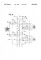
- FIG. 7is an electrical circuit diagram showing the distribution panel of FIG. 1 configured in a third mode for use with a secondary power system
- FIG. 8is an electrical circuit diagram showing the distribution panel of FIG. 1 configured in a fourth mode for use with a secondary power system.
- the inventionis shown connected to a primary power alternating current power supply such as commercial power 10.
- a primary power alternating current power supplysuch as commercial power 10.
- the inventionis designed for use with any alternating current supply.
- commercial poweris supplied through a distribution transformer 12 (FIG. 4) which supplies 240 volts across its secondary windings 14.
- the transformer 12has a center tap 16 which is a grounded neutral voltage N so that 120 volts relative to ground are supplied at each of two supply taps 18 on the secondary windings 14.
- a power distribution panel 22which provides power to a plurality of load circuits 24 and 25.
- the difference between the load circuits 24 and 25will be explained in detail below.
- the distribution panel 22selectively connects the commercial power to the alternating current bus 20 or to a secondary power supply system 40. Details of the distribution panel are discussed below with reference to FIGS. 5-8. For the present discussion it is assumed that the distribution panel 22 connects commercial power 10 to the alternating current bus 20 only through the secondary power supply system 40.
- a first rectifier 42is connected to terminals 34 and thus to the commercial power 10 through the distribution panel 22 to provide direct current to a direct current input node 44.
- the rectifier 42is preferably a phase-controlled, full-wave rectifier including two semiconductor controlled rectifiers 46 (FIG. 3). Many SCR's are suitable, and Powerex #C180D has been used successfully.
- the first rectifier 42is connected to a direct current bus 50.
- a filter 48such as an inductor 49 (FIG. 3) to smooth the rectified current.
- At least one direct current power sourceis also connected to the direct current bus.
- the first DC sourceis an electrical storage battery 52 connected between the DC bus 50 and the neutral N.
- the batteryshould be selected so that it can be charged by the rectified commercial power supplied to the DC bus.
- a lead acid battery having a normal voltage range of 63 to 85 voltsis suitable. The current capacity depends on the number and size of loads to be powered.
- the second DC sourceis an alternating current generator 60 connected to the direct current bus 50 through a second rectifier 62.
- the second rectifier 62is connected at the DC input node 44 so that the rectified current from the generator is filtered by the inductor 49.
- the generator shownis a three-phase wye-connected generator connected to the neutral N.
- the second rectifier 62is a half-wave rectifier including three diodes 63 (FIG. 3).
- the generator 60can be powered by a driver 64 (FIG. 2; not shown in FIG. 3) such as an internal combustion engine fueled by natural gas, gasoline or another fuel, such as LP gas or heating oil.
- a driver 64such as an internal combustion engine fueled by natural gas, gasoline or another fuel, such as LP gas or heating oil.
- the generator 60can be powered by other means which can operate independently from the commercial power supply, such as water from a public supply.
- the use of natural gas or water 69 to power the generator 60is desirable because most homes or facilities in which the present invention would be installed are equipped with water and gas supplies which would supply power indefinitely.
- the generator 60can be equipped to start automatically upon a loss of commercial power for a specified time or when the charge on the battery falls to a specified level.
- the drive means of the generatorcan have a shaft 65 which is equipped to drive an air conditioner compressor 66 or other mechanical device. Exhaust heat from the generator drive means can be directed through a heat duct 67 for use in a heating system 68, an absorption air conditioner or refrigerator, a water heater, a pool, a spa or some other device.
- the DC bus 50is connected to an inverter 70.
- Direct current to alternating current invertersare known in the art and a suitable device would be a pulse-width modulated sine wave inverter including a pair of transistor assemblies 72 (FIG. 3). For example, an assembly of eight International Rectifier #IRFP360 MOSFET's has been found to be suitable.
- An inverter control circuit 74(FIG. 2; not shown in FIG. 3) is provided to control the transistors 72.
- the control circuit 74can also be used to regulate the output of the inverter 70.
- Feedback controllersare known and can be used. Alternatively, where precise voltage regulation is not necessary, in household applications, for example, a controller inversely responsive to the voltage on the DC bus 50 is suitable and avoids stability problems inherent in a feedback controller.
- a filter 76such as an inductor 77 (FIG. 3) and a capacitor 78 (FIG. 3), is connected to the inverter output.
- the autotransformeris preferred to reduce losses and limit its size where isolation is not necessary.
- the first rectifier 42converts the primary power from the commercial power supply 10 to direct current on the DC bus 50.
- the direct currentis then inverted to alternating current on the AC bus 20 by the inverter 70.
- the distribution panel 22controls distribution of the power on the AC bus to various load circuits 24 through fuses and circuit breakers as is known in household and other applications.
- the direct current sourceis a battery 52
- power on the DC bus 50also charges the battery when it is not fully charged. If a generator 60 is used in addition to or in place of the battery, it would normally be idle.
- commercial poweris available, which should be most of the time, this is the mode of operation.
- the primary and secondary power sourcesshould not be connected directly to the AC bus 20 at the same time.
- the battery 52When the commercial power supply is interrupted, the battery 52 provides direct current to the DC bus 50 which is inverted to alternating current on the AC bus 20 by the inverter 70. Power is provided to the load circuits 24 through the distribution panel 22. Thus, there is no interruption in power to the load circuits 24 when the commercial power supply is interrupted. If only the battery 52 is used as the direct current power source, the duration during which the secondary power supply system 40 can supply power is limited by the battery size.
- the generator 60provides an additional power supply. After a specified time or when the charge on the battery falls to a specified level, the generator 60 is started, manually or automatically, to provide power to the DC bus 50 which is inverted to power on the AC bus 20. As shown in FIG. 2A, a voltage detector 82 or a timer 84 can be used to sense a condition and automatically start the driver 64. Thus, power can be maintained during a prolonged commercial power interruption without the need for an exceedingly large battery. When the generator 60 is started automatically and is driven by natural gas or water, the power can be supplied indefinitely without the presence of an operator. The battery 52 remains connected when the generator 60 is operating to recharge the battery 52. Further, the battery 52 can supply momentary peaks in demand which exceed the generator's capacity, thus, a smaller generator 60 can be used.
- the generator driver 64 and its exhaustcan be used for other devices to reduce the electrical load and improve the overall efficiency of the system. Since all of the primary and secondary power sources are connected at the DC bus 50, the generator can be run even when commercial power is available for heating or driving the compressor 66 or other devices discussed above. Electricity generated can supplement the commercial power supply. For example, in hot weather, it may be cost effective to run the generator constantly to drive an air conditioning system such as is indicated at 68.
- the secondary power source 40includes the generator 60 but not the battery 52, it is necessary to keep the generator running constantly to ensure uninterruptible power. Otherwise, there would be a brief interruption in power to the load circuits 24 during the time it would take the generator 60 to start after an interruption of the commercial power supply. It would also be possible to run the generator 60 only when a power interruption appears likely, such as during a thunderstorm. This would not guarantee uninterrupted power, but would reduce the probability of an interruption.
- the power distribution panel 22facilitates installation and maintenance of the secondary power supply system 40.
- the power distribution panelcan be used in one of a number of configurations or modes, and four of these configurations are shown in FIGS. 5-8.
- the primary power supply or commercial power 10is provided to the distribution panel 22 through terminals 16 and 18 and a disconnect circuit breaker 26, which can be internal or external to the distribution panel.
- the commercial poweris connected to the alternating current bus 20 in the panel 22, which in turn is connected to load circuits 24 through circuit breakers 28.
- Non-vital load circuits 25can also be supplied by the commercial power.
- the non-vital load circuits 25supply power to loads which can tolerate discontinuous power without serious adverse consequences. These would include most household lights and appliances.
- Loads which require continuous powersuch as computers, refrigerators and sump pumps, would be powered by load circuits 24.
- the alternating current bus 20 and the primary power supplycan be electrically separated by selective connection means such as a shorting insert 30 (FIG. 5), a bus transfer switch 31 (FIG. 7) (FIG. 5) or a circuit breaker 32 (FIG. 8).
- the shorting insert 30 or jumperis preferably mounted in a block or holder made of insulating material to facilitate safe removal and installation.
- Input terminals 34are provided which can be connected to the secondary power supply system 40 at the input to rectifier 42.
- the input terminals 34are connectable to the commercial power 10 by connection means 35 (FIGS. 6-8) such as a shorting insert or a circuit breaker.
- Output terminals 36are provided for connection to the secondary power system 40 at the output of autotransformer 80.
- the output terminalsare connectable to the AC bus 20 through connection means such as a shorting insert 37 (FIG. 6), the bus transfer switch 31 (FIG. 7) or a circuit breaker 38 (FIG. 8).
- connection meanssuch as a shorting insert 37 (FIG. 6), the bus transfer switch 31 (FIG. 7) or a circuit breaker 38 (FIG. 8).
- the circuit breakers 32 and 38are interlocked to prevent them from both being in a closed state at the same time.
- the distribution panel 22is installed in the same manner as distribution panels commonly in use. Commercial power is supplied to the electrical load circuits 24 and 25 and is controlled by the circuit breakers 28.
- Installation of the secondary power system 40can be accomplished at any time after the distribution panel 22 is installed without disconnecting the commercial power 10 from the distribution panel and with only momentary interruption of power to the load circuits 24.
- the secondary power system 40is connected to the terminals 34 and 36 and the connection means 35 is closed. Power supply to the load circuits 24 is then transferred from the primary power supply 10 to the secondary power system 40 by removing the shorting plug 30 or jumper and inserting the shorting plug 37, which can be the same plug simply moved from one socket to another.
- the bus transfer switch 31(FIG. 7) can be switched or, as shown in FIG. 8, the circuit breaker 32 can be opened and the circuit breaker 38 closed to transfer the power supply.
- the secondary power system 40supplies continuous power to the load circuits 24 as discussed above.
- the primary power supply 10continues to supply power directly to the non-vital load circuits 25 so long as primary power is available. When primary power is not available, the non-vital load circuits 25 do not receive power while the load circuits 24 are powered by the battery or generator of the secondary power system.
Landscapes
- Engineering & Computer Science (AREA)
- Power Engineering (AREA)
- Business, Economics & Management (AREA)
- Emergency Management (AREA)
- Stand-By Power Supply Arrangements (AREA)
- Direct Current Feeding And Distribution (AREA)
Abstract
Description
Claims (17)
Priority Applications (3)
| Application Number | Priority Date | Filing Date | Title |
|---|---|---|---|
| US08/252,749US5532525A (en) | 1994-06-02 | 1994-06-02 | Congeneration power system |
| CA002149845ACA2149845C (en) | 1994-06-02 | 1995-05-23 | Cogeneration power system |
| AU20294/95AAU687528B2 (en) | 1994-06-02 | 1995-05-26 | Cogeneration power system |
Applications Claiming Priority (1)
| Application Number | Priority Date | Filing Date | Title |
|---|---|---|---|
| US08/252,749US5532525A (en) | 1994-06-02 | 1994-06-02 | Congeneration power system |
Publications (1)
| Publication Number | Publication Date |
|---|---|
| US5532525Atrue US5532525A (en) | 1996-07-02 |
Family
ID=22957373
Family Applications (1)
| Application Number | Title | Priority Date | Filing Date |
|---|---|---|---|
| US08/252,749Expired - LifetimeUS5532525A (en) | 1994-06-02 | 1994-06-02 | Congeneration power system |
Country Status (3)
| Country | Link |
|---|---|
| US (1) | US5532525A (en) |
| AU (1) | AU687528B2 (en) |
| CA (1) | CA2149845C (en) |
Cited By (47)
| Publication number | Priority date | Publication date | Assignee | Title |
|---|---|---|---|---|
| WO1997033355A1 (en)* | 1996-03-07 | 1997-09-12 | Nextek Power Systems, Inc. | Modular power management system and method |
| GB2318000A (en)* | 1996-09-13 | 1998-04-08 | Graham Chapman | Uninterruptible power supply |
| US5767591A (en)* | 1996-09-09 | 1998-06-16 | Active Power, Inc. | Method and apparatus for providing startup power to a genset-backed uninterruptible power supply |
| US5803754A (en)* | 1991-01-08 | 1998-09-08 | Nextek Power Systems Inc. | Modified receptacle and plug for low voltage DC distribution |
| US5842027A (en)* | 1993-01-14 | 1998-11-24 | Apple Computer, Inc. | Method and apparatus for supplying power to devices coupled to a bus |
| EP0883225A1 (en)* | 1996-03-06 | 1998-12-09 | Tai Her Yang | System for automatic supervision of storage battery charge in an engine driven standby power unit |
| WO1999008358A1 (en)* | 1997-08-08 | 1999-02-18 | Alpha Technologies, Inc. | Electrical generator employing rotary engine |
| US5910689A (en)* | 1997-04-28 | 1999-06-08 | The Bodine Company, Inc. | Generator standby ballast |
| US5917251A (en)* | 1995-05-08 | 1999-06-29 | Bayernwerk Ag | Method and circuit arrangement to cover peak energy demands in electrical alternating or three-phase current networks |
| US5929538A (en)* | 1997-06-27 | 1999-07-27 | Abacus Controls Inc. | Multimode power processor |
| US5969435A (en)* | 1991-01-08 | 1999-10-19 | Nextek Power Systems, Inc. | Modular DC cogenerator systems |
| US6134124A (en)* | 1999-05-12 | 2000-10-17 | Abb Power T&D Company Inc. | Universal distributed-resource interface |
| US6172432B1 (en) | 1999-06-18 | 2001-01-09 | Gen-Tran Corporation | Automatic transfer switch |
| US6252310B1 (en)* | 1999-07-28 | 2001-06-26 | Nextek Power Systems, Inc. | Balanced modular power management system and method |
| WO2001055577A3 (en)* | 2000-01-25 | 2002-03-14 | Bhkw Betreiber Gmbh | Method and device for generating power and heat |
| AU748683B2 (en)* | 1997-03-19 | 2002-06-13 | Nextek Power Systems, Inc. | High efficiency lighting system |
| WO2002063744A1 (en)* | 2001-02-06 | 2002-08-15 | American Power Conversion Corporation | Integrated uninterruptible power supply enclosure |
| US20020153778A1 (en)* | 2001-04-24 | 2002-10-24 | Oughton George W. | Ferroelectric transformer-free uninterruptible power supply (UPS) systems and methods for communications signal distribution systems |
| US20040070370A1 (en)* | 2001-08-03 | 2004-04-15 | Katsuji Emura | Method for operating power source system and power source system comprising secondary battery |
| US20050012339A1 (en)* | 2003-05-07 | 2005-01-20 | Mikhail Amir S. | Variable speed distributed drive train wind turbine system |
| US20050052029A1 (en)* | 2001-12-20 | 2005-03-10 | Aldridge Wayne Kenneth | Domestic combined heat and power unit |
| US20060192436A1 (en)* | 2002-04-30 | 2006-08-31 | Stranberg John D | Battery connect/disconnect for an uninterruptible power supply |
| US20090015065A1 (en)* | 2004-07-30 | 2009-01-15 | Michael Anthony Becigneul | Centralized powering system and method |
| US20090204838A1 (en)* | 2008-02-07 | 2009-08-13 | Ainet Registry, Llc | Backup power system and method |
| US20090244816A1 (en)* | 2008-03-26 | 2009-10-01 | Siemens Energy & Automation, Inc. | Generator Ready Load Center |
| US20100009724A1 (en)* | 2008-07-10 | 2010-01-14 | Steve Fischer | Cell site power generation |
| US20100019574A1 (en)* | 2008-07-24 | 2010-01-28 | John Baldassarre | Energy management system for auxiliary power source |
| US20100052429A1 (en)* | 2008-08-28 | 2010-03-04 | Nethery Iii Stanton Kee | Power Generation and Control System |
| WO2010038152A1 (en)* | 2008-10-03 | 2010-04-08 | Leaneco Aps | Emergency power supply apparatus |
| US20100275968A1 (en)* | 2009-05-01 | 2010-11-04 | Alpha Technologies Inc. | Solar power systems optimized for use in cold weather conditions |
| EP1959536A3 (en)* | 2007-02-19 | 2011-12-21 | Honda Motor Co., Ltd. | Cogeneration system |
| GB2493631A (en)* | 2011-08-09 | 2013-02-13 | Bae Sys Controls Inc | Portable generator with energy storage system, rectifier and inverter maximising fuel efficiency |
| US8575779B2 (en) | 2010-02-18 | 2013-11-05 | Alpha Technologies Inc. | Ferroresonant transformer for use in uninterruptible power supplies |
| US8983546B2 (en) | 2009-07-24 | 2015-03-17 | T-Mobile Usa, Inc. | Rectifier circuit management system, for use in cell site power systems |
| US9030048B2 (en) | 2010-10-18 | 2015-05-12 | Alpha Technologies Inc. | Uninterruptible power supply systems and methods for communications systems |
| US9030045B2 (en) | 2011-01-23 | 2015-05-12 | Alpha Technologies Inc. | Switching systems and methods for use in uninterruptible power supplies |
| US9037443B1 (en) | 2011-10-16 | 2015-05-19 | Alpha Technologies Inc. | Systems and methods for solar power equipment |
| US9118213B2 (en) | 2010-11-24 | 2015-08-25 | Kohler Co. | Portal for harvesting energy from distributed electrical power sources |
| US9234916B2 (en) | 2012-05-11 | 2016-01-12 | Alpha Technologies Inc. | Status monitoring cables for generators |
| US9312726B2 (en) | 2011-01-23 | 2016-04-12 | Alpha Technologies Inc. | Uninterruptible power supplies for use in a distributed network |
| US9397509B2 (en) | 2011-01-22 | 2016-07-19 | Alpha Technologies Inc. | Charge equalization systems and methods for battery systems and uninterruptible power supplies |
| US9470442B2 (en) | 2013-06-25 | 2016-10-18 | Mcogen, Inc. | Power generation system and method |
| US10074981B2 (en) | 2015-09-13 | 2018-09-11 | Alpha Technologies Inc. | Power control systems and methods |
| US10253993B2 (en) | 2013-08-19 | 2019-04-09 | Mcogen, Inc. | Temperature modulated desiccant evaporative cooler and indirect and direct evaporative air conditioning systems, methods, and apparatus |
| US10381867B1 (en) | 2015-10-16 | 2019-08-13 | Alpha Technologeis Services, Inc. | Ferroresonant transformer systems and methods with selectable input and output voltages for use in uninterruptible power supplies |
| US10635122B2 (en) | 2017-07-14 | 2020-04-28 | Alpha Technologies Services, Inc. | Voltage regulated AC power supply systems and methods |
| US12221043B2 (en)* | 2019-10-25 | 2025-02-11 | Sea Clear Power Inc. | Systems and methods for distribution of power in a marine vessel, ATVS, and vehicles |
Citations (50)
| Publication number | Priority date | Publication date | Assignee | Title |
|---|---|---|---|---|
| US1718238A (en)* | 1917-02-03 | 1929-06-25 | Delco Light Co | System of gas control |
| US2007415A (en)* | 1927-10-25 | 1935-07-09 | Mary C Dunn | Emergency lighting and power unit |
| US2014101A (en)* | 1930-10-22 | 1935-09-10 | Joseph P Bryan | Emergency generating set |
| US2037183A (en)* | 1935-01-30 | 1936-04-14 | Bell Telephone Labor Inc | Carrier line power supply |
| US2063994A (en)* | 1934-06-14 | 1936-12-15 | Westinghouse Electric & Mfg Co | Emergency electric plant |
| US2085072A (en)* | 1934-06-14 | 1937-06-29 | Westinghouse Electric & Mfg Co | Small electric power plant |
| US2165969A (en)* | 1938-06-17 | 1939-07-11 | Reuben L Humbert | Prime mover dynamo plant |
| US2240123A (en)* | 1933-09-16 | 1941-04-29 | Rca Corp | Power supply system |
| US2302192A (en)* | 1940-03-29 | 1942-11-17 | Es B Es Co Ltd | Emergency power system |
| US2427678A (en)* | 1945-08-25 | 1947-09-23 | Werner E F Laging | Auxiliary electrical generating and control system |
| US2688704A (en)* | 1953-05-13 | 1954-09-07 | Us Motors Corp | Motor and engine driven electric generating assemblage |
| US2856543A (en)* | 1956-12-19 | 1958-10-14 | Porter Co H K | Means for maintaining standby power source in immediate readiness |
| US2920211A (en)* | 1955-03-30 | 1960-01-05 | Kokusai Electric Co Ltd | System for generating electric power without interruption |
| US3064195A (en)* | 1960-05-05 | 1962-11-13 | Benco Television Associates Lt | Signal distribution system |
| US3283165A (en)* | 1963-08-22 | 1966-11-01 | Dynamics Corp America | No break power system |
| US3293445A (en)* | 1962-10-01 | 1966-12-20 | Rca Corp | Power supply circuit |
| US3305762A (en)* | 1962-10-17 | 1967-02-21 | Ideal Electric And Mfg Company | Method of control of electric power |
| US3339080A (en)* | 1964-06-24 | 1967-08-29 | Lorain Prod Corp | Dc-ac or ac-dc converter |
| US3345517A (en)* | 1964-02-14 | 1967-10-03 | Dynamics Corp America | Uninterrupted power supply |
| US3348060A (en)* | 1964-01-14 | 1967-10-17 | Lorain Prod Corp | Continuously-operatingstandby powersupply and battery-charging apparatus and method |
| US3435358A (en)* | 1966-06-08 | 1969-03-25 | Anaconda Electronics Co | Cable television amplifier powering |
| US3458710A (en)* | 1966-04-06 | 1969-07-29 | Automatic Power Inc | Emergency power system |
| US3525035A (en)* | 1968-09-30 | 1970-08-18 | Bell Telephone Labor Inc | Closed loop ferroresonant voltage regulator which simulates core saturation |
| US3525078A (en)* | 1965-12-30 | 1970-08-18 | Londex Ltd | Apparatus for transmitting data over electric power supply network |
| US3636368A (en)* | 1970-06-29 | 1972-01-18 | Onan Eastern Corp | Transfer switch and generator control means and new and improved method of operation thereof |
| US3678284A (en)* | 1968-08-27 | 1972-07-18 | Charles Michael Dansey Peters | Energy supply apparatus and method for a building |
| US3691393A (en)* | 1970-04-01 | 1972-09-12 | Christos Papachristou | Automatic starter for internal combustion machines |
| US3859589A (en)* | 1973-06-05 | 1975-01-07 | Charles G Rush | Electric generation apparatus |
| US3943447A (en)* | 1973-10-10 | 1976-03-09 | Comsonics, Inc. | Method and apparatus for bi-directional communication via existing CATV system |
| GB2005118A (en)* | 1977-07-07 | 1979-04-11 | Electricity Council | Generating signal currents in AC power lines |
| US4170761A (en)* | 1977-03-28 | 1979-10-09 | Siemens Aktiengesellschaft | Remotely powered intermediate amplifier for communications transmission |
| US4233558A (en)* | 1978-09-22 | 1980-11-11 | The United States Of America As Represented By The Secretary Of The Navy | Regulated dual DC power supply |
| US4460834A (en)* | 1983-08-29 | 1984-07-17 | Power Group International Corp. | Uninterruptible power system |
| US4475047A (en)* | 1982-04-29 | 1984-10-02 | At&T Bell Laboratories | Uninterruptible power supplies |
| US4667116A (en)* | 1984-10-31 | 1987-05-19 | Mitsubishi Denki Kabushiki Kaisha | Inverter control circuit |
| US4686375A (en)* | 1986-03-05 | 1987-08-11 | Power Group International Corp. | Uninterruptible power supply cogeneration system |
| US4719550A (en)* | 1986-09-11 | 1988-01-12 | Liebert Corporation | Uninterruptible power supply with energy conversion and enhancement |
| US4745299A (en)* | 1986-04-17 | 1988-05-17 | American Telephone And Telegraph Company, At&T Bell Laboratories | Off-line switcher with battery reserve |
| US4748341A (en)* | 1987-03-24 | 1988-05-31 | Rte Deltec Corporation | Uninterruptible power supply |
| US4748342A (en)* | 1985-12-18 | 1988-05-31 | U.S. Philips Corporation | Power supply circuit |
| US4763014A (en)* | 1987-09-21 | 1988-08-09 | American Telephone And Telegraph Company, At&T Bell Laboratories | Backup protection switch to prevent reverse power flow in a UPS |
| US5010469A (en)* | 1990-05-09 | 1991-04-23 | Albar | Uninterruptible power supply with dual level voltage input |
| US5057698A (en)* | 1989-11-13 | 1991-10-15 | Exide Electronics | Shunt circuit for reducing audible noise at low loading conditions of a power supply employing a high frequency resonant converter |
| US5172009A (en)* | 1991-02-25 | 1992-12-15 | Regents Of The University Of Minnesota | Standby power supply with load-current harmonics neutralizer |
| US5185536A (en)* | 1991-09-27 | 1993-02-09 | Exide Electronics | Uninterruptible power supply having improved battery charger |
| US5198698A (en)* | 1991-02-11 | 1993-03-30 | Best Power Technology, Inc. | Auxiliary power supply system for providing dc power on demand |
| US5198970A (en)* | 1988-04-27 | 1993-03-30 | Mitsubishi Denki Kabushiki Kaisha | A.C. power supply apparatus |
| US5237208A (en)* | 1988-10-25 | 1993-08-17 | Nishimu Electronics Industries Co., Ltd. | Apparatus for parallel operation of triport uninterruptable power source devices |
| US5302858A (en)* | 1991-12-11 | 1994-04-12 | Best Power Technology, Incorporated | Method and apparatus for providing battery charging in a backup power system |
| US5347164A (en)* | 1992-10-08 | 1994-09-13 | Accton Technology Corporation | Uninterruptible power supply having a 115V or 230V selectable AC output and power saving |
- 1994
- 1994-06-02USUS08/252,749patent/US5532525A/ennot_activeExpired - Lifetime
- 1995
- 1995-05-23CACA002149845Apatent/CA2149845C/ennot_activeExpired - Lifetime
- 1995-05-26AUAU20294/95Apatent/AU687528B2/ennot_activeExpired
Patent Citations (50)
| Publication number | Priority date | Publication date | Assignee | Title |
|---|---|---|---|---|
| US1718238A (en)* | 1917-02-03 | 1929-06-25 | Delco Light Co | System of gas control |
| US2007415A (en)* | 1927-10-25 | 1935-07-09 | Mary C Dunn | Emergency lighting and power unit |
| US2014101A (en)* | 1930-10-22 | 1935-09-10 | Joseph P Bryan | Emergency generating set |
| US2240123A (en)* | 1933-09-16 | 1941-04-29 | Rca Corp | Power supply system |
| US2063994A (en)* | 1934-06-14 | 1936-12-15 | Westinghouse Electric & Mfg Co | Emergency electric plant |
| US2085072A (en)* | 1934-06-14 | 1937-06-29 | Westinghouse Electric & Mfg Co | Small electric power plant |
| US2037183A (en)* | 1935-01-30 | 1936-04-14 | Bell Telephone Labor Inc | Carrier line power supply |
| US2165969A (en)* | 1938-06-17 | 1939-07-11 | Reuben L Humbert | Prime mover dynamo plant |
| US2302192A (en)* | 1940-03-29 | 1942-11-17 | Es B Es Co Ltd | Emergency power system |
| US2427678A (en)* | 1945-08-25 | 1947-09-23 | Werner E F Laging | Auxiliary electrical generating and control system |
| US2688704A (en)* | 1953-05-13 | 1954-09-07 | Us Motors Corp | Motor and engine driven electric generating assemblage |
| US2920211A (en)* | 1955-03-30 | 1960-01-05 | Kokusai Electric Co Ltd | System for generating electric power without interruption |
| US2856543A (en)* | 1956-12-19 | 1958-10-14 | Porter Co H K | Means for maintaining standby power source in immediate readiness |
| US3064195A (en)* | 1960-05-05 | 1962-11-13 | Benco Television Associates Lt | Signal distribution system |
| US3293445A (en)* | 1962-10-01 | 1966-12-20 | Rca Corp | Power supply circuit |
| US3305762A (en)* | 1962-10-17 | 1967-02-21 | Ideal Electric And Mfg Company | Method of control of electric power |
| US3283165A (en)* | 1963-08-22 | 1966-11-01 | Dynamics Corp America | No break power system |
| US3348060A (en)* | 1964-01-14 | 1967-10-17 | Lorain Prod Corp | Continuously-operatingstandby powersupply and battery-charging apparatus and method |
| US3345517A (en)* | 1964-02-14 | 1967-10-03 | Dynamics Corp America | Uninterrupted power supply |
| US3339080A (en)* | 1964-06-24 | 1967-08-29 | Lorain Prod Corp | Dc-ac or ac-dc converter |
| US3525078A (en)* | 1965-12-30 | 1970-08-18 | Londex Ltd | Apparatus for transmitting data over electric power supply network |
| US3458710A (en)* | 1966-04-06 | 1969-07-29 | Automatic Power Inc | Emergency power system |
| US3435358A (en)* | 1966-06-08 | 1969-03-25 | Anaconda Electronics Co | Cable television amplifier powering |
| US3678284A (en)* | 1968-08-27 | 1972-07-18 | Charles Michael Dansey Peters | Energy supply apparatus and method for a building |
| US3525035A (en)* | 1968-09-30 | 1970-08-18 | Bell Telephone Labor Inc | Closed loop ferroresonant voltage regulator which simulates core saturation |
| US3691393A (en)* | 1970-04-01 | 1972-09-12 | Christos Papachristou | Automatic starter for internal combustion machines |
| US3636368A (en)* | 1970-06-29 | 1972-01-18 | Onan Eastern Corp | Transfer switch and generator control means and new and improved method of operation thereof |
| US3859589A (en)* | 1973-06-05 | 1975-01-07 | Charles G Rush | Electric generation apparatus |
| US3943447A (en)* | 1973-10-10 | 1976-03-09 | Comsonics, Inc. | Method and apparatus for bi-directional communication via existing CATV system |
| US4170761A (en)* | 1977-03-28 | 1979-10-09 | Siemens Aktiengesellschaft | Remotely powered intermediate amplifier for communications transmission |
| GB2005118A (en)* | 1977-07-07 | 1979-04-11 | Electricity Council | Generating signal currents in AC power lines |
| US4233558A (en)* | 1978-09-22 | 1980-11-11 | The United States Of America As Represented By The Secretary Of The Navy | Regulated dual DC power supply |
| US4475047A (en)* | 1982-04-29 | 1984-10-02 | At&T Bell Laboratories | Uninterruptible power supplies |
| US4460834A (en)* | 1983-08-29 | 1984-07-17 | Power Group International Corp. | Uninterruptible power system |
| US4667116A (en)* | 1984-10-31 | 1987-05-19 | Mitsubishi Denki Kabushiki Kaisha | Inverter control circuit |
| US4748342A (en)* | 1985-12-18 | 1988-05-31 | U.S. Philips Corporation | Power supply circuit |
| US4686375A (en)* | 1986-03-05 | 1987-08-11 | Power Group International Corp. | Uninterruptible power supply cogeneration system |
| US4745299A (en)* | 1986-04-17 | 1988-05-17 | American Telephone And Telegraph Company, At&T Bell Laboratories | Off-line switcher with battery reserve |
| US4719550A (en)* | 1986-09-11 | 1988-01-12 | Liebert Corporation | Uninterruptible power supply with energy conversion and enhancement |
| US4748341A (en)* | 1987-03-24 | 1988-05-31 | Rte Deltec Corporation | Uninterruptible power supply |
| US4763014A (en)* | 1987-09-21 | 1988-08-09 | American Telephone And Telegraph Company, At&T Bell Laboratories | Backup protection switch to prevent reverse power flow in a UPS |
| US5198970A (en)* | 1988-04-27 | 1993-03-30 | Mitsubishi Denki Kabushiki Kaisha | A.C. power supply apparatus |
| US5237208A (en)* | 1988-10-25 | 1993-08-17 | Nishimu Electronics Industries Co., Ltd. | Apparatus for parallel operation of triport uninterruptable power source devices |
| US5057698A (en)* | 1989-11-13 | 1991-10-15 | Exide Electronics | Shunt circuit for reducing audible noise at low loading conditions of a power supply employing a high frequency resonant converter |
| US5010469A (en)* | 1990-05-09 | 1991-04-23 | Albar | Uninterruptible power supply with dual level voltage input |
| US5198698A (en)* | 1991-02-11 | 1993-03-30 | Best Power Technology, Inc. | Auxiliary power supply system for providing dc power on demand |
| US5172009A (en)* | 1991-02-25 | 1992-12-15 | Regents Of The University Of Minnesota | Standby power supply with load-current harmonics neutralizer |
| US5185536A (en)* | 1991-09-27 | 1993-02-09 | Exide Electronics | Uninterruptible power supply having improved battery charger |
| US5302858A (en)* | 1991-12-11 | 1994-04-12 | Best Power Technology, Incorporated | Method and apparatus for providing battery charging in a backup power system |
| US5347164A (en)* | 1992-10-08 | 1994-09-13 | Accton Technology Corporation | Uninterruptible power supply having a 115V or 230V selectable AC output and power saving |
Cited By (91)
| Publication number | Priority date | Publication date | Assignee | Title |
|---|---|---|---|---|
| US5786642A (en)* | 1991-01-08 | 1998-07-28 | Nextek Power Systems Inc. | Modular power management system and method |
| US5803754A (en)* | 1991-01-08 | 1998-09-08 | Nextek Power Systems Inc. | Modified receptacle and plug for low voltage DC distribution |
| US6933627B2 (en) | 1991-01-08 | 2005-08-23 | Nextek Power Systems Inc. | High efficiency lighting system |
| US5969435A (en)* | 1991-01-08 | 1999-10-19 | Nextek Power Systems, Inc. | Modular DC cogenerator systems |
| US5842027A (en)* | 1993-01-14 | 1998-11-24 | Apple Computer, Inc. | Method and apparatus for supplying power to devices coupled to a bus |
| US5917251A (en)* | 1995-05-08 | 1999-06-29 | Bayernwerk Ag | Method and circuit arrangement to cover peak energy demands in electrical alternating or three-phase current networks |
| EP0883225A1 (en)* | 1996-03-06 | 1998-12-09 | Tai Her Yang | System for automatic supervision of storage battery charge in an engine driven standby power unit |
| AU734988B2 (en)* | 1996-03-07 | 2001-06-28 | Nextek Power Systems, Inc. | Modular power management system and method |
| WO1997033355A1 (en)* | 1996-03-07 | 1997-09-12 | Nextek Power Systems, Inc. | Modular power management system and method |
| US5767591A (en)* | 1996-09-09 | 1998-06-16 | Active Power, Inc. | Method and apparatus for providing startup power to a genset-backed uninterruptible power supply |
| GB2318000A (en)* | 1996-09-13 | 1998-04-08 | Graham Chapman | Uninterruptible power supply |
| AU748683B2 (en)* | 1997-03-19 | 2002-06-13 | Nextek Power Systems, Inc. | High efficiency lighting system |
| US5910689A (en)* | 1997-04-28 | 1999-06-08 | The Bodine Company, Inc. | Generator standby ballast |
| US5929538A (en)* | 1997-06-27 | 1999-07-27 | Abacus Controls Inc. | Multimode power processor |
| WO1999008358A1 (en)* | 1997-08-08 | 1999-02-18 | Alpha Technologies, Inc. | Electrical generator employing rotary engine |
| US6014015A (en)* | 1997-08-08 | 2000-01-11 | Alpha Technologies, Inc. | Electrical generator employing rotary engine |
| US6134124A (en)* | 1999-05-12 | 2000-10-17 | Abb Power T&D Company Inc. | Universal distributed-resource interface |
| US6172432B1 (en) | 1999-06-18 | 2001-01-09 | Gen-Tran Corporation | Automatic transfer switch |
| US6252310B1 (en)* | 1999-07-28 | 2001-06-26 | Nextek Power Systems, Inc. | Balanced modular power management system and method |
| WO2001055577A3 (en)* | 2000-01-25 | 2002-03-14 | Bhkw Betreiber Gmbh | Method and device for generating power and heat |
| WO2002063744A1 (en)* | 2001-02-06 | 2002-08-15 | American Power Conversion Corporation | Integrated uninterruptible power supply enclosure |
| US6693371B2 (en) | 2001-02-06 | 2004-02-17 | American Power Corporation | Integrated uninterruptible power supply enclosure |
| US20020153778A1 (en)* | 2001-04-24 | 2002-10-24 | Oughton George W. | Ferroelectric transformer-free uninterruptible power supply (UPS) systems and methods for communications signal distribution systems |
| US6933626B2 (en) | 2001-04-24 | 2005-08-23 | Alphatec Ltd. | Ferroelectric transformer-free uninterruptible power supply (UPS) systems and methods for communications signal distribution systems |
| US20040070370A1 (en)* | 2001-08-03 | 2004-04-15 | Katsuji Emura | Method for operating power source system and power source system comprising secondary battery |
| US20050052029A1 (en)* | 2001-12-20 | 2005-03-10 | Aldridge Wayne Kenneth | Domestic combined heat and power unit |
| US7459799B2 (en) | 2001-12-20 | 2008-12-02 | Microgen Energy Limited | Domestic combined heat and power unit |
| US20060192436A1 (en)* | 2002-04-30 | 2006-08-31 | Stranberg John D | Battery connect/disconnect for an uninterruptible power supply |
| US7301249B2 (en)* | 2002-04-30 | 2007-11-27 | American Power Conversion Corporation | Battery connect/disconnect for an uninterruptible power supply |
| US20080157602A1 (en)* | 2002-04-30 | 2008-07-03 | Stranberg John D | Battery connect/disconnect for an uninterruptible power supply |
| US7608944B2 (en) | 2002-04-30 | 2009-10-27 | American Power Conversion | Battery connect/disconnect for an uninterruptible power supply |
| US7042110B2 (en)* | 2003-05-07 | 2006-05-09 | Clipper Windpower Technology, Inc. | Variable speed distributed drive train wind turbine system |
| US20050012339A1 (en)* | 2003-05-07 | 2005-01-20 | Mikhail Amir S. | Variable speed distributed drive train wind turbine system |
| US20090015065A1 (en)* | 2004-07-30 | 2009-01-15 | Michael Anthony Becigneul | Centralized powering system and method |
| EP1959536A3 (en)* | 2007-02-19 | 2011-12-21 | Honda Motor Co., Ltd. | Cogeneration system |
| US7962772B2 (en)* | 2008-02-07 | 2011-06-14 | Ainet Registry, Llc | Backup power system and method |
| US20100235671A9 (en)* | 2008-02-07 | 2010-09-16 | Ainet Registry, Llc | Backup power system and method |
| US20090204838A1 (en)* | 2008-02-07 | 2009-08-13 | Ainet Registry, Llc | Backup power system and method |
| US7855871B2 (en)* | 2008-03-26 | 2010-12-21 | Siemens Industry, Inc. | Generator ready load center |
| US20090244816A1 (en)* | 2008-03-26 | 2009-10-01 | Siemens Energy & Automation, Inc. | Generator Ready Load Center |
| US11082917B2 (en) | 2008-07-10 | 2021-08-03 | T-Mobile Usa, Inc. | Cell site power generation |
| US9386518B2 (en) | 2008-07-10 | 2016-07-05 | T-Mobile Usa, Inc. | Cell site power generation |
| US20100009724A1 (en)* | 2008-07-10 | 2010-01-14 | Steve Fischer | Cell site power generation |
| US10433245B2 (en) | 2008-07-10 | 2019-10-01 | T-Mobile Usa, Inc. | Cell site power generation |
| US8729732B2 (en)* | 2008-07-10 | 2014-05-20 | T-Mobile Usa, Inc. | Cell site power generation |
| US20100019574A1 (en)* | 2008-07-24 | 2010-01-28 | John Baldassarre | Energy management system for auxiliary power source |
| US9906034B2 (en) | 2008-08-28 | 2018-02-27 | Stanton Kee Nethery | Power generation and control system |
| US9083173B2 (en) | 2008-08-28 | 2015-07-14 | Stanton Kee Nethery, III | Power generation and control system |
| US20100052429A1 (en)* | 2008-08-28 | 2010-03-04 | Nethery Iii Stanton Kee | Power Generation and Control System |
| US20110187197A1 (en)* | 2008-10-03 | 2011-08-04 | Leaneco Aps | Emergency power supply apparatus |
| WO2010038152A1 (en)* | 2008-10-03 | 2010-04-08 | Leaneco Aps | Emergency power supply apparatus |
| US9300171B2 (en)* | 2008-10-03 | 2016-03-29 | Leaneco Aps | Emergency power supply apparatus |
| AU2009299462B2 (en)* | 2008-10-03 | 2014-11-06 | Leaneco Aps | Emergency power supply apparatus |
| EA020450B1 (en)* | 2008-10-03 | 2014-11-28 | Леанеко Апс | Emergency power supply apparatus |
| CN102210081B (en)* | 2008-10-03 | 2014-05-14 | 莱尼科有限公司 | Emergency power supply apparatus |
| US20100275968A1 (en)* | 2009-05-01 | 2010-11-04 | Alpha Technologies Inc. | Solar power systems optimized for use in cold weather conditions |
| US8983546B2 (en) | 2009-07-24 | 2015-03-17 | T-Mobile Usa, Inc. | Rectifier circuit management system, for use in cell site power systems |
| US9603089B2 (en) | 2009-07-24 | 2017-03-21 | T-Mobile Usa, Inc. | Rectifier circuit management system, such as for use in cell site power systems |
| US10819144B2 (en) | 2010-02-18 | 2020-10-27 | Alpha Technologies Services, Inc. | Ferroresonant transformer for use in uninterruptible power supplies |
| US9633781B2 (en) | 2010-02-18 | 2017-04-25 | Alpha Technologies Inc. | Ferroresonant transformer for use in uninterruptible power supplies |
| US8575779B2 (en) | 2010-02-18 | 2013-11-05 | Alpha Technologies Inc. | Ferroresonant transformer for use in uninterruptible power supplies |
| US9030048B2 (en) | 2010-10-18 | 2015-05-12 | Alpha Technologies Inc. | Uninterruptible power supply systems and methods for communications systems |
| US9800090B2 (en) | 2010-10-18 | 2017-10-24 | Alpha Technologies Inc. | Uninterruptible power supply systems and methods for communication systems |
| US10965152B2 (en) | 2010-10-18 | 2021-03-30 | Alpha Technologies Services, Inc. | Uninterruptible power supply systems and methods for communication systems |
| US9118213B2 (en) | 2010-11-24 | 2015-08-25 | Kohler Co. | Portal for harvesting energy from distributed electrical power sources |
| US9853497B2 (en) | 2011-01-22 | 2017-12-26 | Alpha Technologies Inc. | Charge equalization systems and methods for battery systems and uninterruptible power supplies |
| US9397509B2 (en) | 2011-01-22 | 2016-07-19 | Alpha Technologies Inc. | Charge equalization systems and methods for battery systems and uninterruptible power supplies |
| US10312728B2 (en) | 2011-01-22 | 2019-06-04 | Alpha Technologies Services, Inc. | Charge equalization systems and methods for battery systems and uninterruptible power supplies |
| US9812900B2 (en) | 2011-01-23 | 2017-11-07 | Alpha Technologies Inc. | Switching systems and methods for use in uninterruptible power supplies |
| US10355521B2 (en) | 2011-01-23 | 2019-07-16 | Alpha Technologies Services, Inc. | Switching systems and methods for use in uninterruptible power supplies |
| US9312726B2 (en) | 2011-01-23 | 2016-04-12 | Alpha Technologies Inc. | Uninterruptible power supplies for use in a distributed network |
| US10103571B2 (en) | 2011-01-23 | 2018-10-16 | Alpha Technologies Inc. | Uninterruptible power supplies for use in a distributed network |
| US9030045B2 (en) | 2011-01-23 | 2015-05-12 | Alpha Technologies Inc. | Switching systems and methods for use in uninterruptible power supplies |
| US8994214B2 (en) | 2011-08-09 | 2015-03-31 | Bae Systems Controls Inc. | Hybrid electric generator set |
| US9705357B2 (en) | 2011-08-09 | 2017-07-11 | Bae Systems Controls Inc. | Hybrid electric generator set |
| GB2493631A (en)* | 2011-08-09 | 2013-02-13 | Bae Sys Controls Inc | Portable generator with energy storage system, rectifier and inverter maximising fuel efficiency |
| CN102957143A (en)* | 2011-08-09 | 2013-03-06 | Bae系统控制有限公司 | Hybrid electric generator set |
| GB2493631B (en)* | 2011-08-09 | 2014-05-07 | Bae Sys Controls Inc | Hybrid electric generator set |
| US10042963B2 (en) | 2011-10-16 | 2018-08-07 | Alpha Technologies Inc. | Systems and methods for solar power equipment |
| US9037443B1 (en) | 2011-10-16 | 2015-05-19 | Alpha Technologies Inc. | Systems and methods for solar power equipment |
| US9234916B2 (en) | 2012-05-11 | 2016-01-12 | Alpha Technologies Inc. | Status monitoring cables for generators |
| US20170104400A1 (en)* | 2013-06-25 | 2017-04-13 | Donald Williams | Power generation system and method |
| US9470442B2 (en) | 2013-06-25 | 2016-10-18 | Mcogen, Inc. | Power generation system and method |
| US10205369B2 (en) | 2013-06-25 | 2019-02-12 | Donald Williams | Power generation system and method |
| US9705389B2 (en)* | 2013-06-25 | 2017-07-11 | Donald Williams | Power generation system and method |
| US10253993B2 (en) | 2013-08-19 | 2019-04-09 | Mcogen, Inc. | Temperature modulated desiccant evaporative cooler and indirect and direct evaporative air conditioning systems, methods, and apparatus |
| US10790665B2 (en) | 2015-09-13 | 2020-09-29 | Alpha Technologies Services, Inc. | Power control systems and methods |
| US10074981B2 (en) | 2015-09-13 | 2018-09-11 | Alpha Technologies Inc. | Power control systems and methods |
| US10381867B1 (en) | 2015-10-16 | 2019-08-13 | Alpha Technologeis Services, Inc. | Ferroresonant transformer systems and methods with selectable input and output voltages for use in uninterruptible power supplies |
| US10635122B2 (en) | 2017-07-14 | 2020-04-28 | Alpha Technologies Services, Inc. | Voltage regulated AC power supply systems and methods |
| US12221043B2 (en)* | 2019-10-25 | 2025-02-11 | Sea Clear Power Inc. | Systems and methods for distribution of power in a marine vessel, ATVS, and vehicles |
Also Published As
| Publication number | Publication date |
|---|---|
| CA2149845A1 (en) | 1995-12-03 |
| AU687528B2 (en) | 1998-02-26 |
| AU2029495A (en) | 1995-12-14 |
| CA2149845C (en) | 2000-02-01 |
Similar Documents
| Publication | Publication Date | Title |
|---|---|---|
| US5532525A (en) | Congeneration power system | |
| EP1151526B1 (en) | Power supply | |
| US6559559B2 (en) | Power system utilizing a DC bus | |
| US6304006B1 (en) | Energy management uninterruptible power supply system | |
| US6128204A (en) | Line power unit for micropower generation | |
| US7782015B1 (en) | Electric power system | |
| US6134124A (en) | Universal distributed-resource interface | |
| RU2294045C2 (en) | Domestic heat and power cogeneration system | |
| US20060202559A1 (en) | Power unit | |
| CN102422101A (en) | System and method for powering a refrigeration unit of a hybrid vehicle | |
| TW200306692A (en) | A power distribution/generation system | |
| US8039991B2 (en) | Cogeneration system with first and second power plants | |
| CN114977474A (en) | Alternating current energy storage system for avoiding shutdown of air conditioner | |
| JP2006230147A (en) | Electric power storing and reduced electric power receiving system | |
| KR102659333B1 (en) | Vehicles with power synchronization method using a one-code power plug | |
| CN2314994Y (en) | Power source for air conditioner of internal conbustion engine driver's cab | |
| JPH0528903Y2 (en) | ||
| JP2002238161A (en) | Output method for generator for distributed power source | |
| RU117048U1 (en) | DEVICE FOR RESERVE ELECTRICAL SUPPLY OF CONSUMERS OF CRANE KNOTS OF OBJECTS OF PIPELINE TRANSPORT | |
| CN113113906A (en) | Groove type solar mirror field LOC local control box power supply system and power supply method | |
| CN119315600A (en) | A multi-module hybrid microgrid energy storage cabin energy management control system and method | |
| CN119154478A (en) | Main and auxiliary frequency conversion co-direct automatic switching speed regulation control system | |
| Zanarini et al. | HYBRID PV–DIESEL POWER GENERATOR: DESIGN CRITERIA AND PRELIMINARY PERFORMANCE ANALYSIS | |
| KR19980085640A (en) | Grid-connected solar power generation system for power failure | |
| Hasan et al. | Performance Analysis of Operating System, Power Generation, Distribution, Maintenance, Controlling and Protection System of Santahar 50MW Peaking Power Plant, Bogura |
Legal Events
| Date | Code | Title | Description |
|---|---|---|---|
| AS | Assignment | Owner name:ALBAR, INC., WASHINGTON Free format text:ASSIGNMENT OF ASSIGNORS INTEREST;ASSIGNORS:KAISER, FREDERICK;BOBRY, HOWARD H.;REEL/FRAME:007404/0272;SIGNING DATES FROM 19940511 TO 19940720 | |
| STCF | Information on status: patent grant | Free format text:PATENTED CASE | |
| FEPP | Fee payment procedure | Free format text:PAT HLDR NO LONGER CLAIMS SMALL ENT STAT AS INDIV INVENTOR (ORIGINAL EVENT CODE: LSM1); ENTITY STATUS OF PATENT OWNER: SMALL ENTITY | |
| FPAY | Fee payment | Year of fee payment:4 | |
| FPAY | Fee payment | Year of fee payment:8 | |
| FEPP | Fee payment procedure | Free format text:PAYOR NUMBER ASSIGNED (ORIGINAL EVENT CODE: ASPN); ENTITY STATUS OF PATENT OWNER: SMALL ENTITY | |
| FEPP | Fee payment procedure | Free format text:PAT HOLDER CLAIMS SMALL ENTITY STATUS, ENTITY STATUS SET TO SMALL (ORIGINAL EVENT CODE: LTOS); ENTITY STATUS OF PATENT OWNER: SMALL ENTITY | |
| AS | Assignment | Owner name:ALPHA TECHNOLOGIES, INC., WASHINGTON Free format text:ASSIGNMENT OF ASSIGNORS INTEREST;ASSIGNOR:ALBAR, INC.;REEL/FRAME:020299/0863 Effective date:20071204 | |
| FPAY | Fee payment | Year of fee payment:12 | |
| REMI | Maintenance fee reminder mailed |