US5531848A - Method of manufacturing of hollow fiber cartridge with porous ring - Google Patents
Method of manufacturing of hollow fiber cartridge with porous ringDownload PDFInfo
- Publication number
- US5531848A US5531848AUS08/443,187US44318795AUS5531848AUS 5531848 AUS5531848 AUS 5531848AUS 44318795 AUS44318795 AUS 44318795AUS 5531848 AUS5531848 AUS 5531848A
- Authority
- US
- United States
- Prior art keywords
- casing
- hollow fiber
- collar
- bundle
- annular
- Prior art date
- Legal status (The legal status is an assumption and is not a legal conclusion. Google has not performed a legal analysis and makes no representation as to the accuracy of the status listed.)
- Expired - Lifetime
Links
Images


Classifications
- B—PERFORMING OPERATIONS; TRANSPORTING
- B01—PHYSICAL OR CHEMICAL PROCESSES OR APPARATUS IN GENERAL
- B01D—SEPARATION
- B01D63/00—Apparatus in general for separation processes using semi-permeable membranes
- B01D63/02—Hollow fibre modules
- B01D63/021—Manufacturing thereof
- B01D63/0233—Manufacturing thereof forming the bundle
- B—PERFORMING OPERATIONS; TRANSPORTING
- B01—PHYSICAL OR CHEMICAL PROCESSES OR APPARATUS IN GENERAL
- B01D—SEPARATION
- B01D63/00—Apparatus in general for separation processes using semi-permeable membranes
- B01D63/02—Hollow fibre modules
- B01D63/031—Two or more types of hollow fibres within one bundle or within one potting or tube-sheet
- B—PERFORMING OPERATIONS; TRANSPORTING
- B01—PHYSICAL OR CHEMICAL PROCESSES OR APPARATUS IN GENERAL
- B01D—SEPARATION
- B01D63/00—Apparatus in general for separation processes using semi-permeable membranes
- B01D63/02—Hollow fibre modules
- B01D63/04—Hollow fibre modules comprising multiple hollow fibre assemblies
- B01D63/046—Hollow fibre modules comprising multiple hollow fibre assemblies in separate housings
- B—PERFORMING OPERATIONS; TRANSPORTING
- B01—PHYSICAL OR CHEMICAL PROCESSES OR APPARATUS IN GENERAL
- B01D—SEPARATION
- B01D65/00—Accessories or auxiliary operations, in general, for separation processes or apparatus using semi-permeable membranes
- B—PERFORMING OPERATIONS; TRANSPORTING
- B01—PHYSICAL OR CHEMICAL PROCESSES OR APPARATUS IN GENERAL
- B01D—SEPARATION
- B01D2313/00—Details relating to membrane modules or apparatus
- B01D2313/20—Specific housing
Definitions
- This inventionrelates broadly to the manufacture of filtering apparatus.
- itrelates to a unique method of sealingly coupling the end of a potted hollow fiber filter bundle to a module casing and the unique collar device used in conjunction therewith.
- Hollow fiber filter modulesare known in the art. Typically, a hollow fiber filter module is comprised of a plurality of porous elongated hollow fibers having an inner diameter of about 100 ⁇ to 1000 ⁇ , packed at a specific density within a casing. Conventional hollow fiber permeability apparatus are used extensively in the medical field, for example in hemodialysis and in artificial lungs. Hollow fiber membrane filters are also extensively used in the purification and desalination of water commonly known as reverse osmosis filtering apparatus.
- Porous, hollow fibersare used in a wide variety of permeability and filter applications because of a basic advantage over flat membranes. Available surface area is increased by choosing porous, hollow fibers thereby reducing space requirements for permeability apparatus.
- the hollow fiber membrane filterstherefore, provide effective filtration of a large variety of different fluids at-an elevated flow rate because of the high density of surface area available for filtration.
- the generally accepted method of manufacturing hollow fiber filter modulesis to retain a rectilinear bundle of hollow fibers within a casing, immerse the longitudinal distal ends of the hollow fiber bundle in a potting compound which will adhere, at least temporarily, to the casing.
- the potting compoundabuts the inner surface of the casing and occupies the interstitial void between the individual fibers thus preventing contaminated liquid from coming into contact with the filtrate.
- a cross-sectional portion of the potting compound from one or both longitudinal ends of the potted fiber bundleis removed thus providing access to the lumen of the individual hollow fibers.
- a difficulty commonly encountered in the construction of the hollow fiber filter modulesis the frequent failure of the potting compound to sealingly bond to the casing and in particular the frequent loss of sealing engagement between the potting compound and the casing after autoclaving of the hollow fiber filter module. This results in the leakage of contaminated fluid into the filtrate. Thus, once or twice autoclaved the module must be discarded.
- This practiceis costly to industries that rely on filtered fluids such as the semi-conductor, pharmaceutical, biotechnology, and medical research industries.
- repeatedly discarding large numbers of non-biodegradable modules out of necessity because reuse is limitedis environmentally unsound.
- the method and apparatus in accordance with the present inventionenables the use of a unique annular porous collar and ring that, as will be shown, (i) permit the repeated autoclaving of filter cartridges without any deleterious breaks in sealing integrity between the potted fiber bundle and the filter module and the potted fiber bundle and the filtrate conduit, respectively, thus making repeated reuse of modules not only feasible but also cost effective; (ii) prevents unfiltered fluids from coming into contact with filtered fluids; and (iii) permits the integrity of the filter module to remain intact during shipment-because the collar and ring prevents separation of the potting plug from the casing and the filtrate conduit caused by stress vibrations.
- the method of sealingly coupling a hollow fiber bundle having first and seconds ends to a casing for encasing said bundle of hollow fibersincluding the steps of: (i) coupling an outer peripheral edge of a porous collar to said casing, said casing having at least one open end with an inner lip proximal to said open end, wherein said outer peripheral edge of said porous collar is coupled along said inner lip; (ii) retaining said bundle of hollow fibers within a chamber defined by said casing; (iii) fluid impermeably potting said open end of said hollow fiber bundle with a fluid impermeable material; and (iv) joining said porous collar to said fluid impermeable material by penetration of said material into said porous collar.
- the methodprovides a fluid impermeable seal between the casing and the individual unpotted hollow fibers.
- the sealprevents the unfiltered substance from coming into contact with filtrate and provides a strong mechanical bond that is impervious to dry heat and/or steam sterilization at temperatures ranging from 100° C. to 150° C. and pressures from 10 psi to 60 psi.
- the unique hollow fiber filter cartridge in accordance with the present inventionbroadly includes (i) a casing for encasing a bundle of hollow fibers, said casing having at least one open end with an inner lip in said casing proximal to said open end; and (ii) a porous collar having first and second peripheral edges, at least one of which is coupled to said casing along said inner ledge.
- a second embodiment of the hollow fiber filter assembly in accordance with the present inventionbroadly includes (i) a casing for encasing a bundle of hollow fibers, said casing defining an interior chamber, said casing having at least one open end with an inner lip in said casing proximal to said open end; (ii) a porous collar having a peripheral edge coupled to said casing along said inner lip; (iii) at least one potting plug comprising a fluid impermeable material; (iv) a bundle of rectilinear hollow fibers disposed within said interior chamber of said casing, said bundle having first and second open ends, at least one of said ends rigidly disposed within said plug; (v) wherein said fluid impermeable material of said potting plug and said porous collar are joined by penetration of said fluid impermeable material into said porous collar.
- the hollow fiber filter assemblymay be subject to dry heat and/or steam sterilization for up to fifteen times without any deleterious breaks in sealing integrity between the potted fiber bundle and the filter module.
- Another advantage of the present inventionis that the porous collar impregnated with the fluid impermeable potting material prevents the unfiltered contaminated fluid from coming into contact with the filtrate.
- Still another advantage of the present inventionis that the integrity of the filter module remains intact during shipment because the collar prevents separation of the potting plug from the casing caused by stress vibrations.
- the present inventionprovides the potential for significant cost reductions in industries utilizing hollow fiber filters by making the multiple reuse of filters practical and economically feasible.
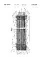
- FIG. 1is an exploded perspective view of one embodiment of the hollow fiber filter cartridge of the present invention
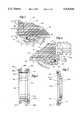
- FIG. 2is a longitudinal cross-sectional view of the hollow fiber filter cartridge taken along line 2--2 in FIG. 1 showing the invention in assembled form;
- FIG. 3is an enlarged fragmentary sectional view of a portion of FIG. 2 showing the juncture of the end cap and the casing;
- FIG. 4is an enlarged fragmentary sectional view of a portion of FIG. 2 showing the juncture of the seal adaptor and the casing;
- FIG. 5is a greatly enlarged transverse section of a longitudinal end of the hollow fiber module depicting the open ended character of the hollow fibers
- FIG. 6is cross-sectional view of a connecting device used to couple multiple filter modules
- FIG. 7is cross-sectional view of a flow control end component of the present invention.
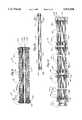
- FIGS. 8a-8eare schematic diagrams depicting the relative positioning of a casing, an annular collar, and a heated platen when practicing one embodiment of the manufacturing process of the present invention.
- the various stagesinclude (i) a start-up stage (FIG. 8a), (ii) a melt stage (FIG. 8b), (iii) a platen-withdrawal stage (FIG. 8c), (iv) a fusing stage ( Figure 8d), and (v) a final stage (FIG. 8e);
- FIG. 9is a cross-sectional view of a second embodiment of a filter cartridge utilizing the porous collar and porous ring of the present invention.
- FIG. 10is a cross-sectional view of the central tube defining a filtrate conduit and porous ring in accordance with the present invention.
- FIG. 11is a cross-sectional view of a fourth embodiment of a filter cartridge in accordance with the present invention.
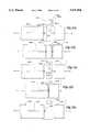
- FIGS. 12a-12eare schematic diagrams depicting the relative positioning of the central tube, an annular ring, and a heated platen when practicing one embodiment of the manufacturing process of the present invention.
- the various stagesinclude (i) a start-up stage (FIG. 12a), (ii) a melt stage (FIG. 12b), (iii) a platen-withdrawal stage (FIG. 12c), (iv) a fusing stage (FIG. 12d), and (v) a final stage (FIG. 12e)
- the hollow fiber filter module 20broadly includes a hollow fiber bundle 30 retained within a generally cylindrical casing 50, or casing means, wherein the longitudinal ends 31a, 31b of the hollow fiber bundle 30 are potted within a potting compound 40.
- the casing 50may have any desired cross-sectional configuration, for example rectangular or square, but for purposes of affording compatibility with a majority of conventional standard commercial filter housings (not shown) the casing 50 preferably has a circular cross-sectional configuration.
- the casing 50has first 51a and second 51b open ends and defines an internal cylindrical chamber 52.
- the internal cylindrical chamber 52preferably has a volume of substantially 5 in 3 to substantially 2000 in 3 , more preferably 10 in 3 to 1000 in 3 , and most preferably has a volume of substantially 15 in 3 to substantially 100 in 3 .
- the ends 51a, 51b of the casing 50are shaped to define laterally extending annular extensions 55 and a longitudinally extending annular flange 56 projecting from the outer periphery of the annular extensions 55 such that the diameter 52d of the chamber 52 defined by the casing 50 is greater at the extreme longitudinal ends 51a,51b of the casing 50.
- Casingsmay be integrally molded to form a unitary piece without perforations or may have, as depicted, a plurality of lateral perforations 57 for facilitating the flow of fluid through the casing 50.
- the extent to which the casing 50 is opened to fluid flowrequires a balancing of the competing needs to provide mechanical support for the rather fragile individual hollow fibers 35 and maximize ingress/egress of fluid through the casing 50.
- casings 50 that are perforatedpreferably will have an open surface area of about 20% to 75% thus providing an effective balance between these competing requirements.
- the casing 50may be made from any fluid impermeable plastic such as polyethylene, polycarbonate, polyvinylchloride and polyethyleneterepthalate; or metals such as stainless steel, aluminum, copper and zinc; or glass.
- the casing 50may also be manufactured using fluid permeable materials, such as porous polypropylene, porous polycarbonate, porous stainless steel, porous brass, or any other suitable material that will melt during a sintering process. Selection of the preferred casing material depends upon a number of factors including the particular fluid to be filtered, compatibility with the potting compound 40, the mechanical abuse to which the casing 50 will be subjected, cost, etc.
- the preferred embodimentis preferably constructed from a thermoplastic resin such as polyethylene, polypropylene, polyvinylchloride, or like plastics.
- Annular, porous collars 60are coupled by heat pressing, fusion welding or other suitable means to the inner, lateral, annular lip 55a proximate the longitudinal open ends 51a,51b of the casing 50 along a first peripheral edge 61a of the collars 60 such that an open-faced annular channel 65 is formed between the longitudinal annual flanges 56 of the casing 50 and the annular, porous collars 60.
- the annular collars 60may be constructed from any material capable of being sealingly coupled to the casing 50 and being permeated by the potting compound 40 to an extent sufficient to create a strong mechanical bond between the collar 60 and the potting compound 40 thereby rendering the collar 60 impermeable to fluid flow.
- Suitable materialsinclude specifically, but not exclusively: porous metals such as sintered aluminum; porous plastics such as foamed polyurethane and sintered polyolefins; and porous glass such as bonded fiberglass.
- porous metalssuch as sintered aluminum
- porous plasticssuch as foamed polyurethane and sintered polyolefins
- porous glasssuch as bonded fiberglass.
- the collar 60must possess a pore size distribution which is effective for ensuring that the potting compound 40 will be able to permeate into the pores thereby creating a strong mechanical sealing bond between the potting compound 40 and the collar 60 as well as render the collar 60 impermeable to the fluid being filtered. While acceptable pore size distributions are clearly dependent upon the particular potting compound 40 which is employed, generally, it is believe that pores of less than about five microns do not generally permit sufficient penetration of the potting compound 40 while pores of greater than about 500 ⁇ tend to weaken the seal between the potting compound 40 and the collar 60 as well as weakening the mechanical bond between the collar 60 and the casing 50.
- the preferred embodiment of the present inventionutilizes a pore size of between 5 ⁇ and 500 ⁇ , and more preferably between 50 ⁇ and 300 ⁇ , and most preferably between 100 ⁇ and 150.
- hollow fiber bundle 30is retained within the chamber 52 defined by the casing 50 with the longitudinal ends 31a, 31b of the fiber bundle 30 projecting past the longitudinal ends 51a, 51b of the casing 50.
- manufacture of hollow fibers 35is widely understood and a wide variety of hollow fibers 35 may be purchased from a number of different sources.
- hollow fibers 35 having an outer diameter as small as about 100 ⁇ and a wall thickness as small as about 10 ⁇may be manufactured from a variety of different materials including polyolefins, polysulfones, polyvinylidene fluoride, cellulose esters, and other suitable materials.
- Selection of the preferred size of the individual hollow fibers 35is generally dependent upon a number of factors including the particular fluid to be filtered, the desired contaminant(s) to be removed, the desired filtration efficiency, etc.
- Individual hollow fibers 35 having an inside diameter 35d of less than about 100 ⁇are difficult and expensive to manufacture wile individual hollow fibers 35 having an inside diameter 35d of greater than about 10000 ⁇ result in a significant decrease in the volumetric density of hollow fiber surface area available for contacting the fluid to be filtered.
- the inside diameter 35d of the individual hollow fibers 35is about 100 ⁇ to about 1000 ⁇ , more preferably about 200 ⁇ to 500 ⁇ and most preferably about 250 ⁇ to 350 ⁇ .
- the external surface area of the hollow fiber bundle available for filtrationis substantially 1 ft 2 to substantially 40 ft 2 .
- the individual hollow fibers 35are those manufactured from polysulfones.
- the packing density of the individual hollow fibers 35 within the hollow fiber bundle 30should be such that the area occupied by the individual hollow fibers 35 is about 30% to 75%, more preferably 40% to 50%, and most preferably 40% to 45% of the casing cross-sectional area available for fibers.
- a packing density of greater than about 75%significantly interferes with the ability to sealingly pot the longitudinal ends 31a,31b of the hollow fiber bundle 30 while a packing density of less than about 40% decreases the filtration capacity of the hollow fiber filter module 20 without any corresponding benefits.
- the longitudinal ends 31a,31b of the hollow fiber bundle 30are sealingly potted with a suitable potting compound 40 which occupies the interstitial void volume between the individual hollow fibers 35 and the annular channel 65 between the longitudinal annular flange 56 of the casing 50 and the annular collar 60.
- the potting compound 40functions to (i) prevent fluid from passing through the interstitial void space 9 between the hollow fibers 35; (ii) fixedly attach the potted hollow fiber filter ends to the case by integrally melding with the porous ring; and (iii) hold the hollow filter fibers together in a bundle.
- a suitable potting compound 40depends upon several variables including the particular fluid to be filtered, the material from which the hollow fibers 35 are constructed, the material from which the casing 50 is constructed, the porosity of the annular collar 60, etc.
- the compound 40must possess sufficient initial fluidity to permit penetration of the potting compound 40 into the interstitial void volume between the individual hollow fibers 35 and into the pores of the annular collar 60 while resulting in a solid plug which is impermeable to the fluid being filtered.
- suitable potting compoundsare well known and include such curable resins as polyurethanes, epoxies, unsaturated polyesters, and silicones.
- the potting compound 40permeates the pores of the annular collar 60 of both the inner 63 and outer 64 peripheral surface so as to render the collar 60 impermeable to fluid flow, prevents fluid flow between the juncture of the potting compound 40 and the collar 60, and forms an extremely strong mechanical bond between the potting compound 40 and the collar 60.
- the longitudinal depth to which the potting compound 40 should be permitted to penetrate into the hollow fiber bundle 30requires a balancing between the competing interests of maximizing the hollow fiber surface area available for effecting filtration (decrease depth) and minimizing the risk of leakage around or through the potting compound 40 (increase depth).
- a depth of about 1 to 5 centimetersprovides an effective balance between these competing interests.
- the potting compound 40in order to improve the effectiveness of the seals between the potting compound 40, collar 60, and casing 50, the potting compound 40 preferably penetrates a sufficient distance into the hollow fiber bundle 30 to extend beyond the juncture of the annular collar 60 and the casing 50 so that the potting compound 40 fills all the pores in the collar 60 and renders the entire length of the collar 60 impermeable to the fluid being filtered.
- the longitudinal ends 31a,31b of the potted hollow fiber bundle 30are cut to open the longitudinal ends 36a, 36b of the hollow fiber lumens 37.
- the hollow fiber filter cartridge 10 utilizing the annular collar of the present inventionis based upon a hollow fiber filter module 20 with flow control end components 100 coupled to the longitudinal ends 21a, 21b of the module 20.
- the flow control end components 100direct the ingress/egress of fluid at the longitudinal ends 21a,21b of the module 20 while maintaining separation of the fluid passing through the lumen 37 of the hollow fibers 35 and the fluid in contact with the outer surface 39 of the hollow fibers 35.
- the first longitudinal end 101a of the flow control end component 100is configured to sealingly engage a longitudinal end 21a,21b of the hollow fiber filter module 20 and is therefore substantially the same regardless of the intended function of the specific flow control end component.
- one embodiment of the first longitudinal end 101a of a flow control end component 100includes an L-shaped in cross section laterally extending annular extension 107, a horizontally extending inner annular flange 105 projecting from the inner periphery of the annular extension 107, and a longitudinally extending inner annular flange 106 projecting from the inner periphery of the annular extension 107.
- Inner annular flange 105fixedly positions O-ring 120 during the welding process. Consequently, the inner annular flange 105 may be omitted if O-ring 120 is not used.
- the outer annular flange 106is configured to match longitudinal ends 51a,51b of the casing 50 for effecting sealing engagement between the flow control end component 100 and the casing 50.
- the inner 105 and outer 106 longitudinal flangescooperate with the annular extension 107 to form an open-faced peripheral annular channel 108.
- the second longitudinal end 101b of the flow control end component 100may take any of several configurations depending upon the intended function of the flow control end component 100.
- the second longitudinal end 100bis simply completely enclosed.
- the second longitudinal end 101bis simply a mirror image of the first longitudinal end 101a for facilitating longitudinal end-to-end coupling of multiple hollow fiber filter modules 20.
- the second longitudinal end 101bincludes a pair of longitudinally spaced, outer, annular, lateral flanges 99 for sealingly engaging the inner surface of an inlet/outlet port (not shown) in conventional filter housings (not shown).
- the flow control end components 100are sealingly attached to the longitudinal ends 21a,21b of the hollow fiber filter module 20 by (i) melting a longitudinal end 21a,21b of the hollow fiber filter module 20, (ii) melting the first longitudinal end 101a of the flow control end component 100, and then (iii) contacting the melted ends under pressure until they sealingly fuse together.
- O-ring 120may be optionally sealingly positioned between the lateral annular extension 107 on the flow control end component 100 and the periphery of the external longitudinal end 42 of the trimmed potting composition 40 to function as a secondary seal against the flow of fluid between the juncture of the hollow fiber filter module 20 and the flow control end component 100.
- An open-faced annular peripheral channel 108may be provided proximate the first longitudinal end 101a of the flow control end component 100 for securing and positioning the O-ring 120.
- FIG. 9depicts an alternative embodiment of the hollow fiber filter cartridge 601 utilizing the present invention.
- the hollow fiber filter cartridge 601includes cylindrical casing or casing means 50' shown enclosing central, nonpermeable tube 604 defining filtrate conduit 603 and a plurality of porous hollow fibers 35'.
- Casing 50'includes an annular, porous collar 60' identical to the annular collar previously discussed.
- the nonpermeable, central tube 604includes annular porous rings 608 with coupling edges 609.
- the porous rings 608, best seen in FIG. 10,are coupled to first and second outer peripheral edges 610, 611 of tube 604 by heat pressing, fusion welding or other suitable means by the method described herein.
- Porous rings 608are constructed, similarly to the annular porous collar 60, from any material capable of being sealingly coupled to the filtrate conduit 604 and of being permeated by the potting compound 40' to an extent sufficient to create a strong mechanical bond between the rings 608 thereby rendering the rings 608 impermeable to fluid flow.
- Suitable materialsinclude porous metals such as sintered aluminum; porous plastics such as foamed polyurethane and sintered polyolefins; and porous glass such as bonded fiberglass. Except for dimensional aspects, All other characteristics, including pore size, are identical to the porous collar 60 previously discussed.
- the assembly of porous, hollow fibers and central tube 604 with porous rings 608has a first potting-impregnated end 612 and a second potting-impregnated end 614.
- First and second ends 612, 614are potted using the conventional means and materials previously disclosed.
- the potting compound 40'permeates the pores of the porous rings 608 of both the inner and outer peripheral surfaces 618, 620 so as to render the rings 608 impermeable to fluid flow and forms an extremely strong mechanical bond between the potting compound 40', the rings 608, the hollow fibers 35', the annular collars 60' and the casing 50'.
- Thisprovides a filter cartridge 601 that is extremely durable and withstands repeated autoclaving without any breaks in integrity.
- the filter cartridge 601 in accordance with the second embodimentmay include an end cap 70 as previously described and an open-ended flow control end component 100 for egress of filtrate.
- fluidenters the perforations 57' of casing 50' and is filtered through the walls of porous, hollow fibers 35' into the bores (not shown) thereof and simultaneously flows toward first and second open ends 615, 616.
- Fluid exiting the porous, hollow fibers 35' at second end 616enters a closed collection chamber (not shown) equivalent to chamber 718 for shunting through central filtrate conduit 603 to the first open end 615 and lower manifold (not shown) equivalent to manifold 720.
- Filtered fluid exiting from porous, hollow fibers 35' at first end 615 and shunted fluid exiting from the filtrate conduit 703 defined by central tube 604flow together out of lower manifold (not shown).
- FIG. 11A third embodiment 701 of a filter cartridge utilizing the present invention is depicted in FIG. 11.
- the filter cartridges utilizing the annular collar and porous ring of the present inventionmay also be connected in series. Stacked filter cartridges are known in the art but for reasons previously stated cannot be used multiple times because repeated autoclaving causes breaks in integrity between the potting compound and the casing. Each casing and each central tube of the "stacked" filter cartridges, therefore, utilizes an annular collar and a porous ring, respectively.
- fluidenters the perforations of housing and is filtered through the walls of porous, hollow fibers 35" into the bores (not shown) thereof and simultaneously flows toward first and second ends 715, 716.
- Fluid exiting the porous, hollow fibers 35" at second end 716enters the closed collection chamber 718 for shunting through central filtrate conduit 704 to lower manifold 720.
- Filtered fluid exiting from porous, hollow fibers 35" at first end 715 and shunted fluid exiting from the filtrate conduit 703 defined by central tube 704flow together out of portal 722 of lower manifold 720 for collection.
- the hollow fiber filter module 20may be constructed by sequentially (i) attaching the annular collars 60 to the casing 50 by heat pressing, fusion welding or other suitable means (ii) inserting the hollow fiber bundle 30 into the casing 50, (iii) potting the longitudinal ends 31a,31b of the hollow fiber bundle 30, and (iv) cutting the longitudinal ends 31a,31b of the potted fiber bundle 30 to permit access to the lumen 37 of the hollow fibers 35.
- the collars 60may be fixedly attached to the inner annular lip 55a of casing 50 along a first longitudinal end 61a of the collars 60 by any means effective for producing a strong bond which is impermeable to the fluid to be filtered. Suitable techniques include adhesive bonding, sonic welding and heat fusing. If the material is other than a plastic, one may achieve a suitable bond by means such as conventional welding, mechanical fasteners, brazing, soldering or other suitable means.
- the hollow fiber bundle 30must be of sufficient longitudinal length such that the longitudinal ends 31a,31b of the fiber bundle 30 project past the longitudinal ends 51a,51b of the casing 50 so that the extreme longitudinal ends 31a,31b of the bundle 30 may be trimmed to permit access to the lumen 37 of the hollow fibers 35 without interference from the casing 50.
- the longitudinal ends 31a,31b of the hollow fiber bundle 30may be effectively potted by injecting the potting material into the hollow fiber bundle and casing, applying centrifugal force to allow the potting compound to flow into the interstitial void volume 9 between hollow fibers 35 and surround the collar 60, removing the combination bundle 30 and casing 50 from the potting compound and then allowing the potting compound 40 to cure. Additionally, one may simply dip the hollow fiber bundle 30 and casing 50 into a supply of the potting compound and then allow the potting compound 40 to cure.
- the longitudinal ends 31a,31b of the potted hollow fiber bundle 30are then cut by any one of the customary procedures, for example, a knife-edged blade having a smooth, toothless edge.
- one method of constructing a hollow fiber filter module 20 having an annular collar 60 sealingly fused to the casing 50is through the use of a transversely reciprocable heated platen 503 and a pair of uniaxially reciprocable retention arms 501,502 configured for retention of the casing 50 and the annular collar 60.
- Heated platen 503includes projection 505 that meltingly contacts casing 50 along the inner, lateral annular lip 55a.
- the "commencement stage" of the processhas the first and second reciprocable retention arms 501,502 separated and the platen 503 withdrawn from between the retention arms 501,502.
- Annular collar 60is positioned within the first reciprocable retention arm 501 with the first longitudinal end 60a of the collar 60 facing the second retention arm 502.
- the casing 50is positioned within the second retention arm 502 with the longitudinal end 50a of the casing 50 to be attached to the annular collar 60 facing the first retention arm 501.
- the "melt stage" of the processhas platen 503 and projection 505, heated to a temperature sufficient to soften the annular collar 60 and the annular lip 55a of casing 50 positioned between the retention arms 501,502 and the retention arms 501,502 extended toward the heated platen 503 until the projection 505 contacts inner, annular lip 55a of the casing 50 and the flat exterior surface 506 of platen 503 contacts the first longitudinal end 60a of the annular collar 60.
- the lip 55a of casing 50 and the annular collar 60are held against the projection 505 and the flat exterior surface 506 of heated platen 503, respectively, for a period of time sufficient to melt the desired depth of material.
- the preferred embodimentcontact the platen 503 with the casing 50 for five seconds.
- the "intermediate stage” of the processeffects separation of the retention arms 501,502 and withdrawal of the heated platen 503 to the positions they occupied during the "commencement stage.”
- the "fusing stage" of the processmaintains the platen 503 in the withdrawn position while the retention arms 501,502 are extended towards one another until the melted inner annular lip 55a of the casing 50 and the melted longitudinal end 60a of the annular collar 60 contact one another.
- the casing 50 and the annular collar 60are pressed against one another until the melted portions are sufficiently melded and solidified to prevent accidental slippage and a unitary component is created.
- Sufficient pressuremust be applied to ensure continuous contact along the entire periphery thereof, generally about 10 to 500 psi.
- the "final stage" of the processmaintains the platen 503 in the withdrawn position while separating the retention arms 501,502 so as to permit removal of the unitary combination of casing 50 and annular collar 60.
- FIG. 12aan almost identical process is utilized for coupling the porous rings 608 to filtrate conduit 604.
- the "commencement stage" of the process depicted in FIG. 12ahas the first and second reciprocable retention arms 501,502 separated and the platen 503 withdrawn from between the retention arms 501,502.
- Annular ring 608is positioned within the first reciprocable retention arm 501 with the coupling edge 609 of ring 608 facing the second retention arm 502.
- the central tube 604is positioned within the second retention arm 502 with the first peripheral edge 610 of tube 604 to be attached to the annular ring 608 facing the first retention arm 501.
- the "melt stage" of the processhas platen 503 heated to a temperature sufficient to soften the annular ring 608 and the central tube 604 positioned between the retention arms 501,502 and the retention arms 501,502 extended toward the heated platen 503 until the first peripheral edge 610 of the filtrate conduit 604 contacts the flat exterior surface 507 of platen 503 and flat exterior surface 506 of platen 503 contacts the coupling edge 609 of ring 608.
- the surfacesare held against the heated platen 503 for a period of time, generally five seconds, sufficient to melt the desired depth of material.
- the "intermediate stage” of the processeffects separation of the retention arms 501,502 and withdrawal of the heated platen 503 to the positions they occupied during the "commencement stage.”
- the "fusing stage" of the processmaintains the platen 503 in the withdrawn position while the retention arms 501,502 are extended towards one another until the melted outer edge of ring 608 and the peripheral edge 610, 611 of filtrate conduit 604 contact one another.
- the conduit 604 and the rings 608are pressed against one another until the melted portions are sufficiently melded and solidified to prevent accidental slippage and a unitary component is created.
- Sufficient pressuremust be applied to ensure continuous contact along the entire periphery thereof, generally about 10 to 500 psi.
- the "final stage" of the processmaintains the platen 503 in the withdrawn position while separating the retention arms 501,502 so as to permit removal of the unitary combination of filtrate conduit 604 with coupled annular porous rings 608.
- one embodiment of the hollow fiber filter cartridge 10is simply placed within a standard commercial filter housing (not shown) with the second longitudinal end 91b of the seal adaptor 90 sealingly engaged within the outlet port (not shown) of the housing (not shown) and the contaminant-containing fluid directed under pressure through an inlet port (not shown) in the housing (not shown) and into contact with the outer surface area 39 of the hollow fibers 35.
- the contaminating fluidcould come in contact with the lumen, rather than the outer surface 39.
- the contaminant-containing fluidflows (i) through the inlet port (not shown) in the housing (not shown) and into contact with the casing 50, (ii) through the perforations 57 in the casing 50 and into the interstitial void volume between the individual hollow fibers 35 located between the potting plugs 40, (iii) through the pores in the walls of the hollow fibers 35 and into the lumen 37 of the hollow fibers 35 so as to remove the contaminants, (v) down the hollow fiber lumen 37 and into the chamber 92 defined by the seal adaptor 90, and finally (vi) out of the filter housing (not shown) through the outlet port (not shown).
- the integral seal created by the method disclosed herein between the annular collar 50 and the casing 60separates the unfiltered contaminant-containing fluid from the filtrate fluid and prevents the unfiltered fluid entering the hollow fibers from contacting the filtrate as it exits into the chamber 92 defined by the seal adaptor 90 and out the outlet port (not shown).
Landscapes
- Chemical & Material Sciences (AREA)
- Chemical Kinetics & Catalysis (AREA)
- Engineering & Computer Science (AREA)
- Manufacturing & Machinery (AREA)
- Separation Using Semi-Permeable Membranes (AREA)
- Spinning Methods And Devices For Manufacturing Artificial Fibers (AREA)
- Apparatus For Disinfection Or Sterilisation (AREA)
- External Artificial Organs (AREA)
- Water Treatment By Sorption (AREA)
Abstract
Description
Claims (6)
Priority Applications (1)
| Application Number | Priority Date | Filing Date | Title |
|---|---|---|---|
| US08/443,187US5531848A (en) | 1992-05-18 | 1995-05-17 | Method of manufacturing of hollow fiber cartridge with porous ring |
Applications Claiming Priority (3)
| Application Number | Priority Date | Filing Date | Title |
|---|---|---|---|
| US88514992A | 1992-05-18 | 1992-05-18 | |
| US08/296,728US5543002A (en) | 1992-05-18 | 1994-08-26 | Method of manufacture of hollow fiber filter cartridge with porous ring |
| US08/443,187US5531848A (en) | 1992-05-18 | 1995-05-17 | Method of manufacturing of hollow fiber cartridge with porous ring |
Related Parent Applications (1)
| Application Number | Title | Priority Date | Filing Date |
|---|---|---|---|
| US08/296,728DivisionUS5543002A (en) | 1992-05-18 | 1994-08-26 | Method of manufacture of hollow fiber filter cartridge with porous ring |
Publications (1)
| Publication Number | Publication Date |
|---|---|
| US5531848Atrue US5531848A (en) | 1996-07-02 |
Family
ID=25386258
Family Applications (3)
| Application Number | Title | Priority Date | Filing Date |
|---|---|---|---|
| US08/296,728Expired - LifetimeUS5543002A (en) | 1992-05-18 | 1994-08-26 | Method of manufacture of hollow fiber filter cartridge with porous ring |
| US08/418,881Expired - LifetimeUS5554283A (en) | 1992-05-18 | 1995-03-31 | Hollow fiber filter having a porous collar/ring seal |
| US08/443,187Expired - LifetimeUS5531848A (en) | 1992-05-18 | 1995-05-17 | Method of manufacturing of hollow fiber cartridge with porous ring |
Family Applications Before (2)
| Application Number | Title | Priority Date | Filing Date |
|---|---|---|---|
| US08/296,728Expired - LifetimeUS5543002A (en) | 1992-05-18 | 1994-08-26 | Method of manufacture of hollow fiber filter cartridge with porous ring |
| US08/418,881Expired - LifetimeUS5554283A (en) | 1992-05-18 | 1995-03-31 | Hollow fiber filter having a porous collar/ring seal |
Country Status (10)
| Country | Link |
|---|---|
| US (3) | US5543002A (en) |
| EP (1) | EP0641247B1 (en) |
| JP (2) | JP2618820B2 (en) |
| AT (1) | ATE144725T1 (en) |
| AU (1) | AU4279493A (en) |
| CA (1) | CA2135672A1 (en) |
| DE (1) | DE69305742T2 (en) |
| DK (1) | DK0641247T3 (en) |
| GR (1) | GR3022069T3 (en) |
| WO (1) | WO1993023152A1 (en) |
Cited By (80)
| Publication number | Priority date | Publication date | Assignee | Title |
|---|---|---|---|---|
| US5753173A (en)* | 1993-10-25 | 1998-05-19 | Minnesota Mining And Manufacturing Company | Method of manufacturing a blood oxygenation system |
| USD402735S (en) | 1998-02-06 | 1998-12-15 | Pleatco Electronic & Filter Corp. | Filter |
| USD403740S (en)* | 1997-12-19 | 1999-01-05 | Pleatco Electronic & Filter Corp. | Filter |
| WO1999003568A1 (en)* | 1997-07-16 | 1999-01-28 | Pall Corporation | Filter assembly |
| US6113782A (en)* | 1998-07-28 | 2000-09-05 | Terumo Cardiovascular Systems Corporation | Potting of tubular bundles in housing |
| US6179131B1 (en) | 1998-06-25 | 2001-01-30 | Pti Technologies, Inc. | Fusion-welded thermoplastic filter assembly and a method of fabricating the same |
| US6270714B1 (en)* | 1998-02-26 | 2001-08-07 | Carbon Membranes Ltd. | Method for potting or casting inorganic hollow fiber membranes into tube sheets |
| US6299772B1 (en)* | 1996-10-10 | 2001-10-09 | The Dow Chemical Company | Fluid filter assemblies with integral fluid seals |
| US20030089659A1 (en)* | 2000-04-10 | 2003-05-15 | Fufang Zha | Hollow fibre restraining system |
| US20030178365A1 (en)* | 1996-12-20 | 2003-09-25 | Fufang Zha | Scouring method |
| US20030205519A1 (en)* | 1998-09-25 | 2003-11-06 | Fufang Zha | Apparatus and method for cleaning membrane filtration modules |
| US20030226797A1 (en)* | 2000-10-23 | 2003-12-11 | Roger Phelps | Fibre membrane arrangement |
| US20030234221A1 (en)* | 2000-10-09 | 2003-12-25 | U.S. Filter Wastewater Group, Inc. | Membrane filtration system |
| US20040000520A1 (en)* | 2001-11-16 | 2004-01-01 | Gallagher Paul Martin | Method of cleaning membranes |
| US20040035782A1 (en)* | 2000-11-13 | 2004-02-26 | Heinz-Joachim Muller | Modified membranes |
| US20040232076A1 (en)* | 1996-12-20 | 2004-11-25 | Fufang Zha | Scouring method |
| US20040238431A1 (en)* | 1999-04-20 | 2004-12-02 | Johnson Warren Thomas | Membrane filtration manifold system |
| US20040238442A1 (en)* | 2001-09-18 | 2004-12-02 | Johnson Warren Thomas | High solids module |
| US20050087898A1 (en)* | 2001-04-04 | 2005-04-28 | U. S. Filter Wastewater Group, Inc. | Potting method |
| US20070084795A1 (en)* | 2005-10-05 | 2007-04-19 | Jordan Edward J | Method and system for treating wastewater |
| US7226541B2 (en) | 2001-06-20 | 2007-06-05 | Siemens Water Technology Corp. | Membrane polymer compositions |
| US7247238B2 (en) | 2002-02-12 | 2007-07-24 | Siemens Water Technologies Corp. | Poly(ethylene chlorotrifluoroethylene) membranes |
| US7387723B2 (en) | 2004-04-22 | 2008-06-17 | Siemens Water Technologies Corp. | Filtration apparatus comprising a membrane bioreactor and a treatment vessel for digesting organic materials |
| US20080237142A1 (en)* | 2007-04-02 | 2008-10-02 | Battelle Energy Alliance, Llc | Systems and methods for concentrating substances in fluid samples |
| US20080276582A1 (en)* | 2004-06-14 | 2008-11-13 | Bruce Allen Boehrs | Air Filter Arrangement; Assembly; and, Methods |
| US7455765B2 (en) | 2006-01-25 | 2008-11-25 | Siemens Water Technologies Corp. | Wastewater treatment system and method |
| US20090041618A1 (en)* | 2007-08-06 | 2009-02-12 | Case Medical Inc. | Reusable porous metal filter |
| US7563363B2 (en) | 2005-10-05 | 2009-07-21 | Siemens Water Technologies Corp. | System for treating wastewater |
| US7591950B2 (en) | 2004-11-02 | 2009-09-22 | Siemens Water Technologies Corp. | Submerged cross-flow filtration |
| US7718057B2 (en) | 2005-10-05 | 2010-05-18 | Siemens Water Technologies Corp. | Wastewater treatment system |
| US7819956B2 (en) | 2004-07-02 | 2010-10-26 | Siemens Water Technologies Corp. | Gas transfer membrane |
| US7862719B2 (en) | 2004-08-20 | 2011-01-04 | Siemens Water Technologies Corp. | Square membrane manifold system |
| US7867417B2 (en) | 2004-12-03 | 2011-01-11 | Siemens Water Technologies Corp. | Membrane post treatment |
| US7938966B2 (en) | 2002-10-10 | 2011-05-10 | Siemens Water Technologies Corp. | Backwash method |
| US7988891B2 (en) | 2005-07-14 | 2011-08-02 | Siemens Industry, Inc. | Monopersulfate treatment of membranes |
| US8057574B2 (en) | 2003-07-08 | 2011-11-15 | Siemens Industry, Inc. | Membrane post treatment |
| US8182687B2 (en) | 2002-06-18 | 2012-05-22 | Siemens Industry, Inc. | Methods of minimising the effect of integrity loss in hollow fibre membrane modules |
| US8268176B2 (en) | 2003-08-29 | 2012-09-18 | Siemens Industry, Inc. | Backwash |
| US8287743B2 (en) | 2007-05-29 | 2012-10-16 | Siemens Industry, Inc. | Membrane cleaning with pulsed airlift pump |
| US8292983B2 (en) | 2005-01-13 | 2012-10-23 | Donaldson Company, Inc. | Air filter cartridge and air cleaner assembly |
| US8293098B2 (en) | 2006-10-24 | 2012-10-23 | Siemens Industry, Inc. | Infiltration/inflow control for membrane bioreactor |
| US8318028B2 (en) | 2007-04-02 | 2012-11-27 | Siemens Industry, Inc. | Infiltration/inflow control for membrane bioreactor |
| US8372282B2 (en) | 2002-12-05 | 2013-02-12 | Siemens Industry, Inc. | Mixing chamber |
| US8377305B2 (en) | 2004-09-15 | 2013-02-19 | Siemens Industry, Inc. | Continuously variable aeration |
| US8382981B2 (en) | 2008-07-24 | 2013-02-26 | Siemens Industry, Inc. | Frame system for membrane filtration modules |
| US8496723B2 (en) | 2005-01-13 | 2013-07-30 | Donaldson Company, Inc. | Air filter arrangement |
| US8496828B2 (en) | 2004-12-24 | 2013-07-30 | Siemens Industry, Inc. | Cleaning in membrane filtration systems |
| US8506806B2 (en) | 2004-09-14 | 2013-08-13 | Siemens Industry, Inc. | Methods and apparatus for removing solids from a membrane module |
| US8512568B2 (en) | 2001-08-09 | 2013-08-20 | Siemens Industry, Inc. | Method of cleaning membrane modules |
| US8524794B2 (en) | 2004-07-05 | 2013-09-03 | Siemens Industry, Inc. | Hydrophilic membranes |
| US8652331B2 (en) | 2008-08-20 | 2014-02-18 | Siemens Water Technologies Llc | Membrane system backwash energy efficiency |
| US8758622B2 (en) | 2004-12-24 | 2014-06-24 | Evoqua Water Technologies Llc | Simple gas scouring method and apparatus |
| US8758621B2 (en) | 2004-03-26 | 2014-06-24 | Evoqua Water Technologies Llc | Process and apparatus for purifying impure water using microfiltration or ultrafiltration in combination with reverse osmosis |
| US8790515B2 (en) | 2004-09-07 | 2014-07-29 | Evoqua Water Technologies Llc | Reduction of backwash liquid waste |
| US8808540B2 (en) | 2003-11-14 | 2014-08-19 | Evoqua Water Technologies Llc | Module cleaning method |
| US8858796B2 (en) | 2005-08-22 | 2014-10-14 | Evoqua Water Technologies Llc | Assembly for water filtration using a tube manifold to minimise backwash |
| US8956464B2 (en) | 2009-06-11 | 2015-02-17 | Evoqua Water Technologies Llc | Method of cleaning membranes |
| US9022224B2 (en) | 2010-09-24 | 2015-05-05 | Evoqua Water Technologies Llc | Fluid control manifold for membrane filtration system |
| DE102014107583A1 (en)* | 2014-05-28 | 2015-12-03 | Sartorius Stedim Biotech Gmbh | Process for producing a hollow fiber module and hollow fiber module |
| US9320997B2 (en) | 2013-06-28 | 2016-04-26 | Donaldson Company, Inc. | Air filter cartridges; air cleaner assemblies; housings; features; components; and, methods |
| US9555370B2 (en) | 2007-09-07 | 2017-01-31 | Donaldson Company, Inc. | Air filter assembly; components thereof; and, methods |
| US9604166B2 (en) | 2011-09-30 | 2017-03-28 | Evoqua Water Technologies Llc | Manifold arrangement |
| US9623351B2 (en) | 2009-04-09 | 2017-04-18 | Cummins Filtration Ip, Inc. | Filtration sealing system |
| US9675938B2 (en) | 2005-04-29 | 2017-06-13 | Evoqua Water Technologies Llc | Chemical clean for membrane filter |
| US9764288B2 (en) | 2007-04-04 | 2017-09-19 | Evoqua Water Technologies Llc | Membrane module protection |
| US9914097B2 (en) | 2010-04-30 | 2018-03-13 | Evoqua Water Technologies Llc | Fluid flow distribution device |
| US9925499B2 (en) | 2011-09-30 | 2018-03-27 | Evoqua Water Technologies Llc | Isolation valve with seal for end cap of a filtration system |
| US9962865B2 (en) | 2012-09-26 | 2018-05-08 | Evoqua Water Technologies Llc | Membrane potting methods |
| US10434454B2 (en) | 2011-06-30 | 2019-10-08 | Donaldson Company, Inc. | Filter cartridge |
| US11020698B2 (en) | 2015-12-11 | 2021-06-01 | Cummins Filtration Ip, Inc. | Filter with variable cross-section axial seal |
| US11110382B2 (en) | 2014-12-27 | 2021-09-07 | Donaldson Company, Inc. | Filter cartridges; air cleaner assemblies; housings; features; components; and, methods |
| US11141687B2 (en) | 2016-05-02 | 2021-10-12 | Cummins Filtration Ip, Inc. | Filter with interlocking housing interface |
| US11167234B2 (en) | 2016-03-18 | 2021-11-09 | Cummins Filtration Ip, Inc. | Interlocked stable filter assembly |
| US11198082B2 (en) | 2017-08-31 | 2021-12-14 | Donaldson Company, Inc. | Filter cartridges; air cleaner assemblies; housings; features; components; and methods |
| US11235275B2 (en) | 2017-03-16 | 2022-02-01 | Cummins Filtration Ip, Inc. | Filtration sealing system |
| US11298640B2 (en) | 2017-01-25 | 2022-04-12 | Cummins Filtration Ip, Inc. | Expandable threaded adaptor for threadless shell |
| US11724220B2 (en) | 2017-02-21 | 2023-08-15 | Cummins Filtration Ip, Inc. | Undulated interlocking housing-endplate interface geometry |
| US11772026B2 (en) | 2014-09-15 | 2023-10-03 | Donaldson Company, Inc. | Filter cartridges; air cleaner assemblies; housings; features; components; and, methods |
| US12263428B2 (en) | 2018-07-23 | 2025-04-01 | Cummins Filtration Sarl | Radial seal for spin-on filter |
| US12324876B2 (en) | 2018-11-01 | 2025-06-10 | Cvd Equipment Corporation | Fluid reactors |
Families Citing this family (49)
| Publication number | Priority date | Publication date | Assignee | Title |
|---|---|---|---|---|
| US5639373A (en) | 1995-08-11 | 1997-06-17 | Zenon Environmental Inc. | Vertical skein of hollow fiber membranes and method of maintaining clean fiber surfaces while filtering a substrate to withdraw a permeate |
| DE69632422T2 (en) | 1995-08-11 | 2005-05-19 | Zenon Environmental Inc., Oakville | Process for embedding hollow fiber membranes |
| US8852438B2 (en) | 1995-08-11 | 2014-10-07 | Zenon Technology Partnership | Membrane filtration module with adjustable header spacing |
| US6685832B2 (en)* | 1995-08-11 | 2004-02-03 | Zenon Environmental Inc. | Method of potting hollow fiber membranes |
| US7087173B2 (en) | 1995-08-11 | 2006-08-08 | Zenon Environmental Inc. | Inverted cavity aerator for membrane module |
| US20040238432A1 (en) | 1995-08-11 | 2004-12-02 | Mailvaganam Mahendran | Membrane filtration module with adjustable header spacing |
| KR970061318A (en)* | 1996-02-28 | 1997-09-12 | 김광호 | Secondary filter device of water purifier |
| US5858232A (en)* | 1996-04-02 | 1999-01-12 | Meissner; Christopher A. | Filter cartridges with sealing means |
| US5851267A (en)* | 1997-01-28 | 1998-12-22 | Uop Llc | Seal arrangement for rapid interconnection or axially arranged separation elements |
| DE19712679A1 (en)* | 1997-03-26 | 1998-10-01 | Mann & Hummel Filter | Air filter |
| CA2289494C (en)* | 1997-04-30 | 2006-08-01 | Mitsubishi Rayon Co., Ltd. | Hollow fiber membrane for the degassing of inks, ink degassing method, ink degassing apparatus, method for the fabrication of an ink cartridge, and ink |
| NL1007899C2 (en) | 1997-12-24 | 1999-06-25 | Dhv Water Bv | Coupling element for membrane elements. |
| US5928450A (en)* | 1998-02-05 | 1999-07-27 | Russell; Daniel Nelson | Process of making fractal tubes |
| US6207053B1 (en)* | 1998-03-12 | 2001-03-27 | Celgard Inc. | Thermoplastic, unibody transfer device |
| TWI222895B (en) | 1998-09-25 | 2004-11-01 | Usf Filtration & Separations | Apparatus and method for cleaning membrane filtration modules |
| US6139739A (en) | 1998-10-08 | 2000-10-31 | Cuno Incorporated | Composite filter element |
| US6156200A (en)* | 1998-12-08 | 2000-12-05 | Usf Filtration & Separations Group, Inc. | Gas-scrubbed hollow fiber membrane module |
| JP3876561B2 (en)* | 1999-03-15 | 2007-01-31 | 宇部興産株式会社 | Gas separation membrane module and gas separation method |
| FR2802115B1 (en)* | 1999-12-14 | 2002-03-01 | Air Liquide | PERMEATION INSTALLATION |
| CA2377814A1 (en) | 2000-05-05 | 2001-11-15 | Zenon Environmental Inc. | Gel potting method for producing filtering hollow fibre membranes |
| US20040072239A1 (en)* | 2000-07-06 | 2004-04-15 | Patricia Renaud | Method for controlling the microbiological quality of an aqueous medium and kit therefor |
| SE518058C2 (en)* | 2000-12-22 | 2002-08-20 | Alfa Laval Ab | Component for supporting a filter member in a port channel to a plate heat exchanger, device comprising a tubular filter member and said component, and plate heat exchanger comprising a tubular filter member and said component |
| NL1017061C2 (en)* | 2001-01-09 | 2002-07-11 | Simon Roelof Vasse | Membrane filter. |
| US6814780B2 (en)* | 2001-05-02 | 2004-11-09 | L'air Liquide, Societe Anonyme A Directoire Et Conseil De Surveillance Pour L'etude Et L'exploitation Des Procedes Georges Claude | Hollow fiber membrane gas separation cartridge and gas purification assembly |
| US6755894B2 (en) | 2001-05-02 | 2004-06-29 | Praxair Technology, Inc. | Hollow fiber membrane gas separation cartridge and gas purification assembly |
| DE10147907B4 (en)* | 2001-09-28 | 2008-07-31 | Fresenius Medical Care Deutschland Gmbh | Filter device and method for its production |
| US6886244B1 (en) | 2002-02-25 | 2005-05-03 | Seagate Technology Llc | Segmented pallet for disk-shaped substrate electrical biassing and apparatus comprising same |
| US6764529B2 (en)* | 2002-07-01 | 2004-07-20 | Bendix Commercial Vehicle Systems Llc | Membrane gas dehydrating apparatus for gas controlled and powered systems |
| US6881245B2 (en)* | 2002-10-18 | 2005-04-19 | Bendix Commercial Vehicle Systems Llc | Membrane air dryer and method of mounting a membrane dryer to a vehicle |
| US6923845B2 (en)* | 2002-10-18 | 2005-08-02 | Bendix Commercial Vehicle Systems Llc | Membrane air dryer for vehicle air brake system |
| EP1706699B1 (en)* | 2003-12-22 | 2011-02-09 | Entegris, Inc. | Exchange device with potted hollow conduits and methods of application |
| FR2865415B1 (en)* | 2004-01-22 | 2007-03-16 | Tech Avancees & Membranes Ind | FILTRATION MODULE DESIGNED TO LIMIT STAGNATION AREAS FOR A LIQUID |
| US7413649B2 (en)* | 2005-07-29 | 2008-08-19 | Gene Bittner | Treatment apparatus with modular chemical containing units having one-way valve assemblies |
| US20080296210A1 (en)* | 2005-07-29 | 2008-12-04 | Gene Bittner | Fluid treatment devices |
| US7938386B2 (en) | 2006-03-13 | 2011-05-10 | GM Global Technology Operations LLC | Fuel cell air humidifier |
| DE102006040214B4 (en)* | 2006-08-28 | 2008-07-10 | Fresenius Medical Care Deutschland Gmbh | A method for combining hollow fibers into a bundle and a hollow fiber bundle produced by this method |
| EP1908509A1 (en)* | 2006-10-03 | 2008-04-09 | Sorin Group Italia S.r.l. | A process for producing exchange devices for medical use and exchange device produced thereby |
| DE102007043330A1 (en)* | 2007-09-12 | 2009-03-19 | Carl Freudenberg Kg | humidifier |
| DE102007052088A1 (en) | 2007-10-31 | 2009-05-07 | M. Mannesmann Gmbh & Co. Kg | Membrane filter for producing Legionella-free water, comprises tubular housing comprising water inlet, water outlet and bundle of membrane hollow fibers, and silver layer provided in a part of the inner surface of the housing |
| EA201100751A1 (en)* | 2008-11-13 | 2011-12-30 | Уайт Фокс Текнолоджиз Лтд. | METHOD OF SEALING MEMBRANE MODULES |
| EP2488286B1 (en)* | 2009-10-12 | 2018-11-21 | Toray Industries, Inc. | Axial labyrinth seal for spiral wound membrane module systems |
| ES2519046T3 (en) | 2009-11-12 | 2014-11-06 | Novomatic Ag | Air cleaner to remove air pollutants from an air stream |
| AU2011205631B2 (en)* | 2010-01-15 | 2014-03-13 | Hydranautics | Brine seal for a filtration device |
| US8945387B2 (en)* | 2011-08-18 | 2015-02-03 | General Electric Company | Hollow fiber membrane module for use in a tubular pressure vessel |
| WO2014004645A1 (en) | 2012-06-28 | 2014-01-03 | Siemens Industry, Inc. | A potting method |
| AU2013323934A1 (en) | 2012-09-27 | 2015-02-26 | Evoqua Water Technologies Llc | Gas scouring apparatus for immersed membranes |
| EP3052221B1 (en) | 2013-10-02 | 2022-12-14 | Rohm & Haas Electronic Materials Singapore Pte. Ltd | Device for repairing a membrane filtration module |
| US10322375B2 (en) | 2015-07-14 | 2019-06-18 | Evoqua Water Technologies Llc | Aeration device for filtration system |
| CN108419412B (en)* | 2018-02-08 | 2020-01-14 | 惠州汉旭五金塑胶科技有限公司 | Water-cooling row with impurity filtering function |
Citations (19)
| Publication number | Priority date | Publication date | Assignee | Title |
|---|---|---|---|---|
| US4038190A (en)* | 1973-05-30 | 1977-07-26 | Rhone-Poulenc S.A. | Fluid fractionation apparatus and method of manufacturing the same |
| US4080296A (en)* | 1977-03-28 | 1978-03-21 | The Dow Chemical Company | Hollow fiber permeator |
| US4132650A (en)* | 1973-11-12 | 1979-01-02 | B. Braun Melsungen Aktiengesellschaft | Fused fiber blood filter |
| US4179380A (en)* | 1976-12-24 | 1979-12-18 | Sodip S.A. | Hollow fibre apparatus |
| US4210536A (en)* | 1978-09-19 | 1980-07-01 | Albany International Corp. | Hollow filament separatory module |
| US4293418A (en)* | 1979-03-28 | 1981-10-06 | Toray Industries, Inc. | Fluid separation apparatus |
| US4361481A (en)* | 1979-05-21 | 1982-11-30 | Baxter Travenol Laboratories, Inc. | Capillary fiber bundles |
| US4374802A (en)* | 1980-09-25 | 1983-02-22 | Terumo Corporation | Oxygenator |
| US4380460A (en)* | 1981-12-21 | 1983-04-19 | Monsanto Company | Gas separation apparatus |
| US4396510A (en)* | 1981-01-08 | 1983-08-02 | Bio-Med Corporation | Mass transfer device |
| US4451369A (en)* | 1980-12-18 | 1984-05-29 | Toyo Boseki Kabushiki Kaisha | Fluid separation apparatus |
| JPS6193803A (en)* | 1984-10-12 | 1986-05-12 | Daicel Chem Ind Ltd | Preparation of hollow yarn type module |
| US4605500A (en)* | 1984-04-24 | 1986-08-12 | Mitsubishi Rayon Co., Ltd. | Hollow-fiber filter module |
| JPS61222510A (en)* | 1985-03-28 | 1986-10-03 | Nitto Electric Ind Co Ltd | Hollow yarn membrane module and its preparation |
| JPS62124496A (en)* | 1985-11-26 | 1987-06-05 | 株式会社東芝 | condensate filtration device |
| US4689149A (en)* | 1981-11-18 | 1987-08-25 | Terumo Corporation | Device for transfer of medical substance |
| US4707268A (en)* | 1982-10-18 | 1987-11-17 | Baxter Travenol Laboratories, Inc. | Hollow fiber potted microfilter |
| US4720342A (en)* | 1984-05-21 | 1988-01-19 | Mitsubishi Rayon Co., Ltd. | Hollow-fiber filter module with filtrate conduit |
| US5160615A (en)* | 1990-04-18 | 1992-11-03 | Terumo Kabushiki Kaisha | Hollow fiber type liquid processing apparatus |
Family Cites Families (16)
| Publication number | Priority date | Publication date | Assignee | Title |
|---|---|---|---|---|
| US2625499A (en)* | 1949-11-22 | 1953-01-13 | Universal Moulded Products Cor | Surfaced fabric and method of making same |
| US2690769A (en)* | 1950-03-29 | 1954-10-05 | Goodyear Tire & Rubber | Laminated structure |
| US2782806A (en)* | 1954-02-17 | 1957-02-26 | Union Carbide & Carbon Corp | Reinforced pipe joint |
| US2974684A (en)* | 1955-11-25 | 1961-03-14 | Bauer Bros Co | Reinforced molded cone |
| US4061574A (en)* | 1977-02-14 | 1977-12-06 | The Dow Chemical Company | Assembly of permeable hollow fibers and a tubesheet supportable at its face and opened by bores parallel thereto |
| JPS5929109A (en)* | 1982-08-11 | 1984-02-16 | 富士スレ−ト株式会社 | Molding device for thick type slate |
| IT8353037U1 (en)* | 1983-03-10 | 1984-09-10 | Sorin Biomedica Spa | Hollow fiber dialysis machine |
| JPS6163240U (en)* | 1984-09-29 | 1986-04-28 | ||
| DE3789671T2 (en)* | 1987-07-28 | 1994-11-17 | Minntech Corp | FILTER CARTRIDGE. |
| JPS6420963U (en)* | 1987-07-30 | 1989-02-01 | ||
| SE454847B (en)* | 1987-08-31 | 1988-06-06 | Gambro Dialysatoren | DEVICE FOR DIFFUSION AND / OR FILTERING AND PROCEDURE FOR MANUFACTURING THIS DEVICE |
| SE465095B (en)* | 1988-07-07 | 1991-07-22 | Gambro Dialysatoren | SEALING INCLUDING A RING OF A FLEXIBLE MATERIAL INTENDED TO BE PRESSED BETWEEN TWO PARALLEL, PRELIMINALLY SMALL SEALING SURFACES |
| DE3916511A1 (en)* | 1989-05-20 | 1990-12-13 | Seitz Filter Werke | MEMBRANE FILTER DEVICE FOR MICRO AND ULTRAFILTRATION OF FLUIDS IN THE CROSSFLOW PROCESS |
| US5092914A (en)* | 1990-06-07 | 1992-03-03 | Multiform Desiccants, Inc. | Floatable oxygen-absorbing cartridge |
| US5328541A (en)* | 1991-12-11 | 1994-07-12 | Kureha Kagaku Kogyo Kabushiki Kaisha | Method of welding tubular products of polyarylene sulfide and welded tubular structure |
| US5342464A (en)* | 1992-04-24 | 1994-08-30 | United Technologies Corporation | Bonding of thermoplastic composite structures to metal structures |
- 1993
- 1993-04-05DEDE69305742Tpatent/DE69305742T2/ennot_activeExpired - Fee Related
- 1993-04-05JPJP5520213Apatent/JP2618820B2/ennot_activeExpired - Fee Related
- 1993-04-05WOPCT/US1993/003252patent/WO1993023152A1/enactiveIP Right Grant
- 1993-04-05DKDK93912136.4Tpatent/DK0641247T3/enactive
- 1993-04-05ATAT93912136Tpatent/ATE144725T1/ennot_activeIP Right Cessation
- 1993-04-05EPEP93912136Apatent/EP0641247B1/ennot_activeExpired - Lifetime
- 1993-04-05CACA002135672Apatent/CA2135672A1/ennot_activeAbandoned
- 1993-04-05AUAU42794/93Apatent/AU4279493A/ennot_activeAbandoned
- 1994
- 1994-08-26USUS08/296,728patent/US5543002A/ennot_activeExpired - Lifetime
- 1995
- 1995-03-31USUS08/418,881patent/US5554283A/ennot_activeExpired - Lifetime
- 1995-05-17USUS08/443,187patent/US5531848A/ennot_activeExpired - Lifetime
- 1996
- 1996-09-26JPJP25435596Apatent/JP3374262B2/ennot_activeExpired - Fee Related
- 1996-12-18GRGR960403514Tpatent/GR3022069T3/enunknown
Patent Citations (22)
| Publication number | Priority date | Publication date | Assignee | Title |
|---|---|---|---|---|
| US4038190A (en)* | 1973-05-30 | 1977-07-26 | Rhone-Poulenc S.A. | Fluid fractionation apparatus and method of manufacturing the same |
| US4132650A (en)* | 1973-11-12 | 1979-01-02 | B. Braun Melsungen Aktiengesellschaft | Fused fiber blood filter |
| US4179380A (en)* | 1976-12-24 | 1979-12-18 | Sodip S.A. | Hollow fibre apparatus |
| US4080296A (en)* | 1977-03-28 | 1978-03-21 | The Dow Chemical Company | Hollow fiber permeator |
| US4210536A (en)* | 1978-09-19 | 1980-07-01 | Albany International Corp. | Hollow filament separatory module |
| US4293418A (en)* | 1979-03-28 | 1981-10-06 | Toray Industries, Inc. | Fluid separation apparatus |
| US4361481A (en)* | 1979-05-21 | 1982-11-30 | Baxter Travenol Laboratories, Inc. | Capillary fiber bundles |
| US4374802A (en)* | 1980-09-25 | 1983-02-22 | Terumo Corporation | Oxygenator |
| US4451369A (en)* | 1980-12-18 | 1984-05-29 | Toyo Boseki Kabushiki Kaisha | Fluid separation apparatus |
| US4396510A (en)* | 1981-01-08 | 1983-08-02 | Bio-Med Corporation | Mass transfer device |
| US4689149A (en)* | 1981-11-18 | 1987-08-25 | Terumo Corporation | Device for transfer of medical substance |
| US4380460A (en)* | 1981-12-21 | 1983-04-19 | Monsanto Company | Gas separation apparatus |
| US4707268A (en)* | 1982-10-18 | 1987-11-17 | Baxter Travenol Laboratories, Inc. | Hollow fiber potted microfilter |
| US4605500A (en)* | 1984-04-24 | 1986-08-12 | Mitsubishi Rayon Co., Ltd. | Hollow-fiber filter module |
| US4720342A (en)* | 1984-05-21 | 1988-01-19 | Mitsubishi Rayon Co., Ltd. | Hollow-fiber filter module with filtrate conduit |
| US4781832A (en)* | 1984-05-21 | 1988-11-01 | Mitsubishi Rayon Co., Ltd. | Hollow-fiber filter module |
| US4781832B1 (en)* | 1984-05-21 | 1993-05-18 | Mitsubishi Rayon Co. Ltd. | Hollow-fiber filter module |
| US4720342B1 (en)* | 1984-05-21 | 1993-05-18 | Mitsubishi Rayon Co.,Ltd. | Hollow-fiber filter module with filtrate conduit |
| JPS6193803A (en)* | 1984-10-12 | 1986-05-12 | Daicel Chem Ind Ltd | Preparation of hollow yarn type module |
| JPS61222510A (en)* | 1985-03-28 | 1986-10-03 | Nitto Electric Ind Co Ltd | Hollow yarn membrane module and its preparation |
| JPS62124496A (en)* | 1985-11-26 | 1987-06-05 | 株式会社東芝 | condensate filtration device |
| US5160615A (en)* | 1990-04-18 | 1992-11-03 | Terumo Kabushiki Kaisha | Hollow fiber type liquid processing apparatus |
Non-Patent Citations (1)
| Title |
|---|
| Rodriguez, Principles of Polymer Systems, Copyright 1982, 1970, p. 326.* |
Cited By (157)
| Publication number | Priority date | Publication date | Assignee | Title |
|---|---|---|---|---|
| US5753173A (en)* | 1993-10-25 | 1998-05-19 | Minnesota Mining And Manufacturing Company | Method of manufacturing a blood oxygenation system |
| US6299772B1 (en)* | 1996-10-10 | 2001-10-09 | The Dow Chemical Company | Fluid filter assemblies with integral fluid seals |
| US20030178365A1 (en)* | 1996-12-20 | 2003-09-25 | Fufang Zha | Scouring method |
| US20040145076A1 (en)* | 1996-12-20 | 2004-07-29 | Fufang Zha | Scouring method |
| US8048306B2 (en) | 1996-12-20 | 2011-11-01 | Siemens Industry, Inc. | Scouring method |
| US20040084369A1 (en)* | 1996-12-20 | 2004-05-06 | U.S. Filter Wastewater Group, Inc. | Scouring method |
| US20040168979A1 (en)* | 1996-12-20 | 2004-09-02 | Fufang Zha | Scouring method |
| US20040178154A1 (en)* | 1996-12-20 | 2004-09-16 | Pall Filtration And Separations Group Inc. | Scouring method |
| US20040232076A1 (en)* | 1996-12-20 | 2004-11-25 | Fufang Zha | Scouring method |
| WO1999003568A1 (en)* | 1997-07-16 | 1999-01-28 | Pall Corporation | Filter assembly |
| USD403740S (en)* | 1997-12-19 | 1999-01-05 | Pleatco Electronic & Filter Corp. | Filter |
| USD402735S (en) | 1998-02-06 | 1998-12-15 | Pleatco Electronic & Filter Corp. | Filter |
| US6270714B1 (en)* | 1998-02-26 | 2001-08-07 | Carbon Membranes Ltd. | Method for potting or casting inorganic hollow fiber membranes into tube sheets |
| US6179131B1 (en) | 1998-06-25 | 2001-01-30 | Pti Technologies, Inc. | Fusion-welded thermoplastic filter assembly and a method of fabricating the same |
| US6113782A (en)* | 1998-07-28 | 2000-09-05 | Terumo Cardiovascular Systems Corporation | Potting of tubular bundles in housing |
| US6821420B2 (en) | 1998-09-25 | 2004-11-23 | U. S. Filter Wastewater Group, Inc. | Apparatus and method for cleaning membrane filtration modules |
| US20030205519A1 (en)* | 1998-09-25 | 2003-11-06 | Fufang Zha | Apparatus and method for cleaning membrane filtration modules |
| US20040238431A1 (en)* | 1999-04-20 | 2004-12-02 | Johnson Warren Thomas | Membrane filtration manifold system |
| US7264716B2 (en) | 1999-04-20 | 2007-09-04 | Siemens Water Technologies Corp. | Membrane filtration manifold system |
| US20070209993A1 (en)* | 2000-04-10 | 2007-09-13 | Fufang Zha | Hollow fibre restraining system |
| US6783008B2 (en) | 2000-04-10 | 2004-08-31 | U.S. Filter Wastewater Group, Inc. | Hollow fibre restraining system |
| US20030089659A1 (en)* | 2000-04-10 | 2003-05-15 | Fufang Zha | Hollow fibre restraining system |
| US6962258B2 (en) | 2000-04-10 | 2005-11-08 | U.S. Filter Wastewater Group, Inc. | Hollow fiber restraining system |
| US20040262215A1 (en)* | 2000-04-10 | 2004-12-30 | Fufang Zha | Hollow fibre restraining system |
| US20030234221A1 (en)* | 2000-10-09 | 2003-12-25 | U.S. Filter Wastewater Group, Inc. | Membrane filtration system |
| US6872305B2 (en) | 2000-10-09 | 2005-03-29 | U.S. Filter Wastewater Group, Inc. | Membrane filtration system |
| US20030226797A1 (en)* | 2000-10-23 | 2003-12-11 | Roger Phelps | Fibre membrane arrangement |
| US7404896B2 (en) | 2000-11-13 | 2008-07-29 | Siemens Water Technologies Corp. | Modified membranes |
| US20040035782A1 (en)* | 2000-11-13 | 2004-02-26 | Heinz-Joachim Muller | Modified membranes |
| US6884350B2 (en) | 2000-11-13 | 2005-04-26 | U.S. Filter Wastewater Group, Inc. | Modified membranes |
| US20050029185A1 (en)* | 2000-11-13 | 2005-02-10 | Heinz-Joachim Muller | Modified membranes |
| US7300022B2 (en) | 2000-11-13 | 2007-11-27 | Siemens Water Technologies Corp. | Modified membranes |
| US20050087898A1 (en)* | 2001-04-04 | 2005-04-28 | U. S. Filter Wastewater Group, Inc. | Potting method |
| US8518256B2 (en) | 2001-04-04 | 2013-08-27 | Siemens Industry, Inc. | Membrane module |
| US6974554B2 (en) | 2001-04-04 | 2005-12-13 | U.S. Filter Wastewater Group, Inc. | Potting method |
| US7931463B2 (en) | 2001-04-04 | 2011-04-26 | Siemens Water Technologies Corp. | Apparatus for potting membranes |
| US7226541B2 (en) | 2001-06-20 | 2007-06-05 | Siemens Water Technology Corp. | Membrane polymer compositions |
| US8512568B2 (en) | 2001-08-09 | 2013-08-20 | Siemens Industry, Inc. | Method of cleaning membrane modules |
| US7018533B2 (en) | 2001-09-18 | 2006-03-28 | U.S. Filter Wastewater Group, Inc. | High solids module |
| US20040238442A1 (en)* | 2001-09-18 | 2004-12-02 | Johnson Warren Thomas | High solids module |
| US20050218073A1 (en)* | 2001-11-16 | 2005-10-06 | Gallagher Paul M | Method of cleaning membranes |
| US6955762B2 (en) | 2001-11-16 | 2005-10-18 | U. S. Filter Wastewater Group, Inc. | Method of cleaning membranes |
| US20040000520A1 (en)* | 2001-11-16 | 2004-01-01 | Gallagher Paul Martin | Method of cleaning membranes |
| US7632439B2 (en) | 2002-02-12 | 2009-12-15 | Siemens Water Technologies Corp. | Poly(ethylene chlorotrifluoroethylene) membranes |
| US7247238B2 (en) | 2002-02-12 | 2007-07-24 | Siemens Water Technologies Corp. | Poly(ethylene chlorotrifluoroethylene) membranes |
| US8182687B2 (en) | 2002-06-18 | 2012-05-22 | Siemens Industry, Inc. | Methods of minimising the effect of integrity loss in hollow fibre membrane modules |
| US7938966B2 (en) | 2002-10-10 | 2011-05-10 | Siemens Water Technologies Corp. | Backwash method |
| US8372282B2 (en) | 2002-12-05 | 2013-02-12 | Siemens Industry, Inc. | Mixing chamber |
| US8262778B2 (en) | 2003-07-08 | 2012-09-11 | Siemens Industry, Inc. | Membrane post treatment |
| US8057574B2 (en) | 2003-07-08 | 2011-11-15 | Siemens Industry, Inc. | Membrane post treatment |
| US8268176B2 (en) | 2003-08-29 | 2012-09-18 | Siemens Industry, Inc. | Backwash |
| US8808540B2 (en) | 2003-11-14 | 2014-08-19 | Evoqua Water Technologies Llc | Module cleaning method |
| US8758621B2 (en) | 2004-03-26 | 2014-06-24 | Evoqua Water Technologies Llc | Process and apparatus for purifying impure water using microfiltration or ultrafiltration in combination with reverse osmosis |
| US7718065B2 (en) | 2004-04-22 | 2010-05-18 | Siemens Water Technologies Corp. | Filtration method and apparatus |
| US7387723B2 (en) | 2004-04-22 | 2008-06-17 | Siemens Water Technologies Corp. | Filtration apparatus comprising a membrane bioreactor and a treatment vessel for digesting organic materials |
| US11291943B2 (en) | 2004-06-14 | 2022-04-05 | Donaldson Company, Inc. | Air filter arrangement; assembly; and, methods |
| US8480779B2 (en)* | 2004-06-14 | 2013-07-09 | Donaldson Company, Inc. | Air filter arrangement; assembly; and, methods |
| US8034145B2 (en) | 2004-06-14 | 2011-10-11 | Donaldson Company, Inc. | Air filter arrangement; assembly; and, methods |
| US9120047B2 (en) | 2004-06-14 | 2015-09-01 | Donaldson Company, Inc. | Air filter arrangement; assembly; and, methods |
| US9937455B2 (en) | 2004-06-14 | 2018-04-10 | Donaldson Company, Inc. | Air filter arrangement; assembly; and, methods |
| US20080276582A1 (en)* | 2004-06-14 | 2008-11-13 | Bruce Allen Boehrs | Air Filter Arrangement; Assembly; and, Methods |
| US10603618B2 (en) | 2004-06-14 | 2020-03-31 | Donaldson Company, Inc. | Air filter arrangement; assembly; and, methods |
| US7819956B2 (en) | 2004-07-02 | 2010-10-26 | Siemens Water Technologies Corp. | Gas transfer membrane |
| US8524794B2 (en) | 2004-07-05 | 2013-09-03 | Siemens Industry, Inc. | Hydrophilic membranes |
| US7862719B2 (en) | 2004-08-20 | 2011-01-04 | Siemens Water Technologies Corp. | Square membrane manifold system |
| US8790515B2 (en) | 2004-09-07 | 2014-07-29 | Evoqua Water Technologies Llc | Reduction of backwash liquid waste |
| US8506806B2 (en) | 2004-09-14 | 2013-08-13 | Siemens Industry, Inc. | Methods and apparatus for removing solids from a membrane module |
| US8377305B2 (en) | 2004-09-15 | 2013-02-19 | Siemens Industry, Inc. | Continuously variable aeration |
| US7591950B2 (en) | 2004-11-02 | 2009-09-22 | Siemens Water Technologies Corp. | Submerged cross-flow filtration |
| US7867417B2 (en) | 2004-12-03 | 2011-01-11 | Siemens Water Technologies Corp. | Membrane post treatment |
| US8758622B2 (en) | 2004-12-24 | 2014-06-24 | Evoqua Water Technologies Llc | Simple gas scouring method and apparatus |
| US8496828B2 (en) | 2004-12-24 | 2013-07-30 | Siemens Industry, Inc. | Cleaning in membrane filtration systems |
| US10864475B2 (en) | 2005-01-13 | 2020-12-15 | Donaldson Company, Inc. | Air filter arrangement; assembly; and, methods |
| US10065145B2 (en) | 2005-01-13 | 2018-09-04 | Donaldson Company, Inc. | Air filter arrangement; assembly; and, methods |
| US11951429B2 (en) | 2005-01-13 | 2024-04-09 | Donaldson Company, Inc. | Air filter arrangement; assembly; and, methods |
| US12070711B2 (en) | 2005-01-13 | 2024-08-27 | Donaldson Company, Inc. | Air filter arrangement; assembly; and, methods |
| US10421034B2 (en) | 2005-01-13 | 2019-09-24 | Donaldson Company, Inc. | Air filter arrangement; assembly; and, methods |
| US12138574B2 (en) | 2005-01-13 | 2024-11-12 | Donaldson Company, Inc. | Air Filter Arrangement; Assembly; and, Methods |
| US9180399B2 (en) | 2005-01-13 | 2015-11-10 | Donaldson Company, Inc. | Air filter arrangement |
| US10315144B2 (en) | 2005-01-13 | 2019-06-11 | Donaldson Company, Inc. | Air filter arrangement; assembly; and, methods |
| US11826689B2 (en) | 2005-01-13 | 2023-11-28 | Donaldson Company, Inc. | Air filter arrangement; assembly; and, methods |
| US8636820B2 (en) | 2005-01-13 | 2014-01-28 | Donaldson Company, Inc. | Air filter arrangement |
| US9527023B2 (en) | 2005-01-13 | 2016-12-27 | Donaldson Comapny, Inc. | Air filter arrangement; assembly; and, methods |
| US8709119B2 (en) | 2005-01-13 | 2014-04-29 | Donaldson Company, Inc. | Air filter cartridge and air cleaner assembly |
| US8496723B2 (en) | 2005-01-13 | 2013-07-30 | Donaldson Company, Inc. | Air filter arrangement |
| US11020699B2 (en) | 2005-01-13 | 2021-06-01 | Donaldson Company, Inc. | Air filter arrangement; assembly; and, methods |
| US8292983B2 (en) | 2005-01-13 | 2012-10-23 | Donaldson Company, Inc. | Air filter cartridge and air cleaner assembly |
| US9675938B2 (en) | 2005-04-29 | 2017-06-13 | Evoqua Water Technologies Llc | Chemical clean for membrane filter |
| US7988891B2 (en) | 2005-07-14 | 2011-08-02 | Siemens Industry, Inc. | Monopersulfate treatment of membranes |
| US8858796B2 (en) | 2005-08-22 | 2014-10-14 | Evoqua Water Technologies Llc | Assembly for water filtration using a tube manifold to minimise backwash |
| US8894858B1 (en) | 2005-08-22 | 2014-11-25 | Evoqua Water Technologies Llc | Method and assembly for water filtration using a tube manifold to minimize backwash |
| US7722769B2 (en) | 2005-10-05 | 2010-05-25 | Siemens Water Technologies Corp. | Method for treating wastewater |
| US20070084795A1 (en)* | 2005-10-05 | 2007-04-19 | Jordan Edward J | Method and system for treating wastewater |
| US7718057B2 (en) | 2005-10-05 | 2010-05-18 | Siemens Water Technologies Corp. | Wastewater treatment system |
| US7563363B2 (en) | 2005-10-05 | 2009-07-21 | Siemens Water Technologies Corp. | System for treating wastewater |
| US7455765B2 (en) | 2006-01-25 | 2008-11-25 | Siemens Water Technologies Corp. | Wastewater treatment system and method |
| US8293098B2 (en) | 2006-10-24 | 2012-10-23 | Siemens Industry, Inc. | Infiltration/inflow control for membrane bioreactor |
| US8623202B2 (en) | 2007-04-02 | 2014-01-07 | Siemens Water Technologies Llc | Infiltration/inflow control for membrane bioreactor |
| US8318028B2 (en) | 2007-04-02 | 2012-11-27 | Siemens Industry, Inc. | Infiltration/inflow control for membrane bioreactor |
| US20080237142A1 (en)* | 2007-04-02 | 2008-10-02 | Battelle Energy Alliance, Llc | Systems and methods for concentrating substances in fluid samples |
| US9764288B2 (en) | 2007-04-04 | 2017-09-19 | Evoqua Water Technologies Llc | Membrane module protection |
| US9573824B2 (en) | 2007-05-29 | 2017-02-21 | Evoqua Water Technologies Llc | Membrane cleaning with pulsed airlift pump |
| US8372276B2 (en) | 2007-05-29 | 2013-02-12 | Siemens Industry, Inc. | Membrane cleaning with pulsed airlift pump |
| US9206057B2 (en) | 2007-05-29 | 2015-12-08 | Evoqua Water Technologies Llc | Membrane cleaning with pulsed airlift pump |
| US10507431B2 (en) | 2007-05-29 | 2019-12-17 | Evoqua Water Technologies Llc | Membrane cleaning with pulsed airlift pump |
| US8622222B2 (en) | 2007-05-29 | 2014-01-07 | Siemens Water Technologies Llc | Membrane cleaning with pulsed airlift pump |
| US8840783B2 (en) | 2007-05-29 | 2014-09-23 | Evoqua Water Technologies Llc | Water treatment membrane cleaning with pulsed airlift pump |
| US8287743B2 (en) | 2007-05-29 | 2012-10-16 | Siemens Industry, Inc. | Membrane cleaning with pulsed airlift pump |
| US20090041618A1 (en)* | 2007-08-06 | 2009-02-12 | Case Medical Inc. | Reusable porous metal filter |
| US9555370B2 (en) | 2007-09-07 | 2017-01-31 | Donaldson Company, Inc. | Air filter assembly; components thereof; and, methods |
| US10422306B2 (en) | 2007-09-07 | 2019-09-24 | Donaldson Company, Inc. | Air filter assembly; components thereof; and, methods |
| US9023206B2 (en) | 2008-07-24 | 2015-05-05 | Evoqua Water Technologies Llc | Frame system for membrane filtration modules |
| US8382981B2 (en) | 2008-07-24 | 2013-02-26 | Siemens Industry, Inc. | Frame system for membrane filtration modules |
| US8652331B2 (en) | 2008-08-20 | 2014-02-18 | Siemens Water Technologies Llc | Membrane system backwash energy efficiency |
| US10112138B2 (en) | 2009-04-09 | 2018-10-30 | Cummins Filtration Ip, Inc. | Filtration sealing system |
| US9782708B2 (en) | 2009-04-09 | 2017-10-10 | Cummins Filtration Ip, Inc. | Filtration sealing system |
| US9623351B2 (en) | 2009-04-09 | 2017-04-18 | Cummins Filtration Ip, Inc. | Filtration sealing system |
| US11833459B2 (en) | 2009-04-09 | 2023-12-05 | Cummins Filtration Ip, Inc. | Filtration sealing system |
| US8956464B2 (en) | 2009-06-11 | 2015-02-17 | Evoqua Water Technologies Llc | Method of cleaning membranes |
| US9914097B2 (en) | 2010-04-30 | 2018-03-13 | Evoqua Water Technologies Llc | Fluid flow distribution device |
| US10441920B2 (en) | 2010-04-30 | 2019-10-15 | Evoqua Water Technologies Llc | Fluid flow distribution device |
| US9022224B2 (en) | 2010-09-24 | 2015-05-05 | Evoqua Water Technologies Llc | Fluid control manifold for membrane filtration system |
| US10434454B2 (en) | 2011-06-30 | 2019-10-08 | Donaldson Company, Inc. | Filter cartridge |
| US9925499B2 (en) | 2011-09-30 | 2018-03-27 | Evoqua Water Technologies Llc | Isolation valve with seal for end cap of a filtration system |
| US9604166B2 (en) | 2011-09-30 | 2017-03-28 | Evoqua Water Technologies Llc | Manifold arrangement |
| US10391432B2 (en) | 2011-09-30 | 2019-08-27 | Evoqua Water Technologies Llc | Manifold arrangement |
| US9962865B2 (en) | 2012-09-26 | 2018-05-08 | Evoqua Water Technologies Llc | Membrane potting methods |
| US12186694B2 (en) | 2013-06-28 | 2025-01-07 | Donaldson Company, Inc. | Filter cartridges; air cleaner assemblies; housings; features; components; and, methods |
| US12115484B2 (en) | 2013-06-28 | 2024-10-15 | Donaldson Company, Inc. | Filter cartridges; air cleaner assemblies; housings; features; components; and, methods |
| US9320997B2 (en) | 2013-06-28 | 2016-04-26 | Donaldson Company, Inc. | Air filter cartridges; air cleaner assemblies; housings; features; components; and, methods |
| US11752460B2 (en) | 2013-06-28 | 2023-09-12 | Donaldson Company, Inc. | Filter cartridges; air cleaner assemblies; housings; features; components; and, methods |
| US10046260B2 (en) | 2013-06-28 | 2018-08-14 | Donaldson Company, Inc. | Air filter cartridges; air cleaner assemblies; housings; features; components; and, methods |
| US11298643B2 (en) | 2013-06-28 | 2022-04-12 | Donaldson Company, Inc. | Filter cartridges; air cleaner assemblies; housings; features; components; and, methods |
| US10610816B2 (en) | 2013-06-28 | 2020-04-07 | Donaldson Company, Inc. | Filter cartridges; air cleaner assemblies; housings; features; components; and, methods |
| DE102014107583B4 (en) | 2014-05-28 | 2018-10-25 | Sartorius Stedim Biotech Gmbh | Process for producing a hollow fiber module and hollow fiber module |
| DE102014107583A1 (en)* | 2014-05-28 | 2015-12-03 | Sartorius Stedim Biotech Gmbh | Process for producing a hollow fiber module and hollow fiber module |
| DE102014107583A8 (en)* | 2014-05-28 | 2016-03-17 | Sartorius Stedim Biotech Gmbh | Process for producing a hollow fiber module and hollow fiber module |
| US10166511B2 (en) | 2014-05-28 | 2019-01-01 | Sartorius Stedim Biotech Gmbh | Method for the production of a hollow fiber module, and hollow fiber module |
| US11772026B2 (en) | 2014-09-15 | 2023-10-03 | Donaldson Company, Inc. | Filter cartridges; air cleaner assemblies; housings; features; components; and, methods |
| US12145093B2 (en) | 2014-09-15 | 2024-11-19 | Donaldson Company, Inc. | Filter cartridges; air cleaner assemblies; housings; features; components; and, methods |
| US11110382B2 (en) | 2014-12-27 | 2021-09-07 | Donaldson Company, Inc. | Filter cartridges; air cleaner assemblies; housings; features; components; and, methods |
| US12168194B2 (en) | 2014-12-27 | 2024-12-17 | Donaldson Company, Inc. | Filter cartridges; air cleaner assemblies; housings; features; components; and, methods |
| US11020698B2 (en) | 2015-12-11 | 2021-06-01 | Cummins Filtration Ip, Inc. | Filter with variable cross-section axial seal |
| US11167234B2 (en) | 2016-03-18 | 2021-11-09 | Cummins Filtration Ip, Inc. | Interlocked stable filter assembly |
| US11813559B2 (en) | 2016-03-18 | 2023-11-14 | Cummins Filtration Ip, Inc. | Interlocked stable filter assembly |
| US11141687B2 (en) | 2016-05-02 | 2021-10-12 | Cummins Filtration Ip, Inc. | Filter with interlocking housing interface |
| US11660560B2 (en) | 2016-05-02 | 2023-05-30 | Cummins Filtration Ip, Inc. | Filter with interlocking housing interface |
| US11298640B2 (en) | 2017-01-25 | 2022-04-12 | Cummins Filtration Ip, Inc. | Expandable threaded adaptor for threadless shell |
| US11724220B2 (en) | 2017-02-21 | 2023-08-15 | Cummins Filtration Ip, Inc. | Undulated interlocking housing-endplate interface geometry |
| US12330099B2 (en) | 2017-02-21 | 2025-06-17 | Cummins Filtration Ip, Inc. | Undulated interlocking housing-endplate interface geometry |
| US11235275B2 (en) | 2017-03-16 | 2022-02-01 | Cummins Filtration Ip, Inc. | Filtration sealing system |
| US12036499B2 (en) | 2017-08-31 | 2024-07-16 | Donaldson Company, Inc | Filter cartridges; air cleaner assemblies; housings; features; components; and, methods |
| US11801466B2 (en) | 2017-08-31 | 2023-10-31 | Donaldson Company, Inc. | Filter cartridges; air cleaner assemblies; housings; features; components; and, methods |
| US11198082B2 (en) | 2017-08-31 | 2021-12-14 | Donaldson Company, Inc. | Filter cartridges; air cleaner assemblies; housings; features; components; and methods |
| US12357934B2 (en) | 2017-08-31 | 2025-07-15 | Donaldson Company, Inc. | Filter cartridges; air cleaner assemblies; housings; features; components; and, methods |
| US12263428B2 (en) | 2018-07-23 | 2025-04-01 | Cummins Filtration Sarl | Radial seal for spin-on filter |
| US12324876B2 (en) | 2018-11-01 | 2025-06-10 | Cvd Equipment Corporation | Fluid reactors |
Also Published As
| Publication number | Publication date |
|---|---|
| US5543002A (en) | 1996-08-06 |
| EP0641247B1 (en) | 1996-10-30 |
| JP3374262B2 (en) | 2003-02-04 |
| GR3022069T3 (en) | 1997-03-31 |
| DK0641247T3 (en) | 1997-04-01 |
| JPH07503407A (en) | 1995-04-13 |
| WO1993023152A1 (en) | 1993-11-25 |
| AU4279493A (en) | 1993-12-13 |
| EP0641247A1 (en) | 1995-03-08 |
| DE69305742D1 (en) | 1996-12-05 |
| US5554283A (en) | 1996-09-10 |
| ATE144725T1 (en) | 1996-11-15 |
| DE69305742T2 (en) | 1997-04-10 |
| JP2618820B2 (en) | 1997-06-11 |
| CA2135672A1 (en) | 1993-11-25 |
| JPH09234351A (en) | 1997-09-09 |
Similar Documents
| Publication | Publication Date | Title |
|---|---|---|
| US5531848A (en) | Method of manufacturing of hollow fiber cartridge with porous ring | |
| US6103119A (en) | Filter cartridges having track etched membranes and methods of making same | |
| US5053130A (en) | Diffusion and/or filtration apparatus | |
| US5266195A (en) | Spiral wound separation device and method of making same | |
| US4231871A (en) | Artificial kidney and method for making same | |
| US4707268A (en) | Hollow fiber potted microfilter | |
| GB1602060A (en) | Artificial kidney and method for making same | |
| EP1146944B1 (en) | Perfluorinated thermoplastic filter cartridge | |
| JP2001506536A (en) | Lens-shaped filter cartridge enclosed in a capsule | |
| JPS61167407A (en) | Preparation of hollow yarn filtration membrane module | |
| WO1996013322A2 (en) | Spirally wound filter cartridge with longitudinal bypass | |
| CA1106770A (en) | Hollow fiber dialysis | |
| US5225079A (en) | Modular hollow-fiber filter unit | |
| GB2218919A (en) | Filter | |
| WO1984001522A1 (en) | Filter | |
| US3698560A (en) | Hollow fiber, artificial kidney with disposable dialyzing cartridge | |
| JPS6397203A (en) | Filtration cartridge | |
| JPS61240964A (en) | Body fluid treating device and its production | |
| CA2782461A1 (en) | Methods for making a hollow fiber filtration apparatus enclosed by two thermoplastic parts | |
| JPH04330919A (en) | Production of hollow fiber bundle cartridge and cartridge case used therefor | |
| JPS59160511A (en) | filtration device | |
| JPS6330482Y2 (en) | ||
| JPH01164405A (en) | Filter element | |
| JPH02284631A (en) | Membrane separator | |
| JPH0626652B2 (en) | Hollow fiber bundle assembly |
Legal Events
| Date | Code | Title | Description |
|---|---|---|---|
| STCF | Information on status: patent grant | Free format text:PATENTED CASE | |
| FPAY | Fee payment | Year of fee payment:4 | |
| AS | Assignment | Owner name:FLEET NATIONAL BANK, AS AGENT, MASSACHUSETTS Free format text:SECURITY INTEREST;ASSIGNOR:MINNTECH CORPORATION;REEL/FRAME:012438/0922 Effective date:20010907 | |
| FEPP | Fee payment procedure | Free format text:PAT HOLDER NO LONGER CLAIMS SMALL ENTITY STATUS, ENTITY STATUS SET TO UNDISCOUNTED (ORIGINAL EVENT CODE: STOL); ENTITY STATUS OF PATENT OWNER: LARGE ENTITY | |
| FPAY | Fee payment | Year of fee payment:8 | |
| AS | Assignment | Owner name:BANK OF AMERICA, N.A., AS ADMINISTRATIVE AGENT, MA Free format text:NOTICE OF GRANT OF SECURITY INTEREST;ASSIGNOR:MINNTECH CORPORATION;REEL/FRAME:016883/0590 Effective date:20050801 | |
| FPAY | Fee payment | Year of fee payment:12 | |
| AS | Assignment | Owner name:BANK OF AMERICA, N.A., AS ADMINISTRATIVE AGENT, MA Free format text:NOTICE OF GRANT OF SECURITY INTEREST IN PATENTS;ASSIGNOR:MINNTECH CORPORATION;REEL/FRAME:026693/0692 Effective date:20110801 | |
| AS | Assignment | Owner name:MINNTECH CORPORATION, MINNESOTA Free format text:ASSIGNMENT OF ASSIGNORS INTEREST;ASSIGNORS:BRINDA, PAUL D.;COSENTINO, LOUIS C.;REEL/FRAME:027174/0373 Effective date:19940826 | |
| AS | Assignment | Owner name:MEDIVATORS INC., MINNESOTA Free format text:CHANGE OF NAME;ASSIGNOR:MINNTECH CORPORATION;REEL/FRAME:028698/0842 Effective date:20120801 | |
| AS | Assignment | Owner name:MINNTECH CORPORATION, NEW JERSEY Free format text:TERMINATION AND RELEASE OF SECURITY INTEREST IN PATENTS;ASSIGNOR:BANK OF AMERICA, N.A., AS ADMINISTRATIVE AGENT;REEL/FRAME:056470/0021 Effective date:20210602 Owner name:MINNTECH CORPORATION, NEW JERSEY Free format text:TERMINATION AND RELEASE OF SECURITY INTEREST IN PATENTS;ASSIGNOR:BANK OF AMERICA, N.A., AS ADMINISTRATIVE AGENT;REEL/FRAME:056593/0336 Effective date:20210602 |