US5531764A - Implantable defibrillator system and method having successive changeable defibrillation waveforms - Google Patents
Implantable defibrillator system and method having successive changeable defibrillation waveformsDownload PDFInfo
- Publication number
- US5531764A US5531764AUS08/227,563US22756394AUS5531764AUS 5531764 AUS5531764 AUS 5531764AUS 22756394 AUS22756394 AUS 22756394AUS 5531764 AUS5531764 AUS 5531764A
- Authority
- US
- United States
- Prior art keywords
- countershock
- countershocks
- sequence
- waveform
- subsequent
- Prior art date
- Legal status (The legal status is an assumption and is not a legal conclusion. Google has not performed a legal analysis and makes no representation as to the accuracy of the status listed.)
- Expired - Lifetime
Links
- 238000000034methodMethods0.000titleclaimsdescription8
- 239000003990capacitorSubstances0.000claimsdescription31
- 238000002560therapeutic procedureMethods0.000claimsdescription7
- 206010003119arrhythmiaDiseases0.000claims18
- 238000007599dischargingMethods0.000claims8
- 230000004044responseEffects0.000claims6
- 238000001514detection methodMethods0.000claims1
- 230000035939shockEffects0.000abstractdescription70
- 230000003111delayed effectEffects0.000abstractdescription27
- 210000005241right ventricleAnatomy0.000description25
- 210000002620vena cava superiorAnatomy0.000description10
- 206010061592cardiac fibrillationDiseases0.000description5
- 230000002600fibrillogenic effectEffects0.000description5
- 210000005245right atriumAnatomy0.000description4
- 230000001746atrial effectEffects0.000description2
- 238000006243chemical reactionMethods0.000description2
- 230000015572biosynthetic processEffects0.000description1
- 230000002051biphasic effectEffects0.000description1
- 230000006931brain damageEffects0.000description1
- 231100000874brain damageToxicity0.000description1
- 208000029028brain injuryDiseases0.000description1
- 230000001934delayEffects0.000description1
- 230000000694effectsEffects0.000description1
- 230000002427irreversible effectEffects0.000description1
- 210000005246left atriumAnatomy0.000description1
- 210000005240left ventricleAnatomy0.000description1
- 238000012986modificationMethods0.000description1
- 230000004048modificationEffects0.000description1
- 230000037361pathwayEffects0.000description1
- 239000007787solidSubstances0.000description1
Images


Classifications
- A—HUMAN NECESSITIES
- A61—MEDICAL OR VETERINARY SCIENCE; HYGIENE
- A61N—ELECTROTHERAPY; MAGNETOTHERAPY; RADIATION THERAPY; ULTRASOUND THERAPY
- A61N1/00—Electrotherapy; Circuits therefor
- A61N1/18—Applying electric currents by contact electrodes
- A61N1/32—Applying electric currents by contact electrodes alternating or intermittent currents
- A61N1/38—Applying electric currents by contact electrodes alternating or intermittent currents for producing shock effects
- A61N1/39—Heart defibrillators
- A61N1/3956—Implantable devices for applying electric shocks to the heart, e.g. for cardioversion
- A—HUMAN NECESSITIES
- A61—MEDICAL OR VETERINARY SCIENCE; HYGIENE
- A61N—ELECTROTHERAPY; MAGNETOTHERAPY; RADIATION THERAPY; ULTRASOUND THERAPY
- A61N1/00—Electrotherapy; Circuits therefor
- A61N1/18—Applying electric currents by contact electrodes
- A61N1/32—Applying electric currents by contact electrodes alternating or intermittent currents
- A61N1/38—Applying electric currents by contact electrodes alternating or intermittent currents for producing shock effects
- A61N1/39—Heart defibrillators
- A61N1/3906—Heart defibrillators characterised by the form of the shockwave
- Y—GENERAL TAGGING OF NEW TECHNOLOGICAL DEVELOPMENTS; GENERAL TAGGING OF CROSS-SECTIONAL TECHNOLOGIES SPANNING OVER SEVERAL SECTIONS OF THE IPC; TECHNICAL SUBJECTS COVERED BY FORMER USPC CROSS-REFERENCE ART COLLECTIONS [XRACs] AND DIGESTS
- Y02—TECHNOLOGIES OR APPLICATIONS FOR MITIGATION OR ADAPTATION AGAINST CLIMATE CHANGE
- Y02E—REDUCTION OF GREENHOUSE GAS [GHG] EMISSIONS, RELATED TO ENERGY GENERATION, TRANSMISSION OR DISTRIBUTION
- Y02E60/00—Enabling technologies; Technologies with a potential or indirect contribution to GHG emissions mitigation
- Y02E60/10—Energy storage using batteries
Definitions
- the present inventionpertains to the field of heart defibrillators, and more particularly, relates to delivery of programmable and sequenced waveforms to areas of the heart by the components of a defibrillator.
- Prior art defibrillatorsdeliver a number of successive shocks for heart defibrillation.
- the same waveform in these devicesis repeated in succession usually to deliver four shock waveforms.
- the particular handicap or drawback with these devicesis that the repeated similar waveforms are determined by the manufacturer, and cannot be changed unless a reimplant of the device is accomplished.
- the prior art devicesused only a repeated similar waveform instead of waveforms of different magnitudes and shapes to accomplish the defibrillation process.
- the present inventionovercomes the inadequacies of the prior art by providing a programmable defibrillator which can deliver shock waveforms of different shapes and magnitude in different combinations of sequences which are field programmable by a physician.
- an implantable defibrillatorbegins a sequence of activities that involve charging the output capacitors and verifying that fibrillation is still present before delivering the first shock pulse. After a shock pulse is delivered, the device continues to monitor the heart rate, and if it determines that the shock was unsuccessful in terminating the fibrillation, the implanted defibrillator will deliver a second shock, at the same or higher energy. This sequence can be repeated several times up to four times in currently available devices, after which the device terminates further attempts at conversion.
- the rationale for terminating therapy after four shocksis that further attempts are unlikely to be successful in that conversion thresholds tend to increase with time in a fibrillation episode, and after fibrillating for long periods, the patient is likely to have suffered irreversible brain damage.
- the shocksare being delivered inappropriately due to noise on the leads or component failure, the patient will receive no more than four unnecessary shocks.
- the deviceresets itself after the heart rate has slowed to a normal level for a prescribed length of time.
- shock waveformshave generally lower defibrillation thresholds than others.
- the most efficient shock waveformmay not be the one installed in the implanted prior art device.
- this implantable defibrillatoris that the shock waveform is programmable so that the implanting physician can select the waveform that yields the lowest threshold for a given patient and electrode configuration.
- the invented implantable defibrillatorallows the physician to program the device such that each successive shock waveform may be programmed independently.
- the rationaleis that if the first and earliest shock failed, it would be better to try a new waveform on the next shock rather than to repeat a shock waveform that has just demonstrated failure to defibrillate.
- an implantable defibrillatorincluding a patch electrode for application to the heart, and another lead having sensing electrodes and defibrillation electrodes which are aligned in the right atrium and the right ventricle.
- a physician-programmable computerincluding a memory for storing programmable waveform information, is included in the can of the defibrillator.
- One significant aspect and feature of the present inventionis a defibrillator which is physician programmable.
- Another significant aspect and feature of the present inventionis a defibrillator which has a variety of waveforms which can be sequentially applied in the defibrillation process.
- a further significant aspect and feature of the present inventionis the selective steering of desired waveforms through the heart to the components of the defibrillator.
- Still another significant aspect and feature of the present inventionis time-sequenced delays of waveform application.
- FIG. 1illustrates an implantable programmable defibrillator, the present invention, connected to a heart;
- FIG. 2illustrates a representative waveform
- FIG. 3illustrates another representative waveform
- FIG. 4illustrates another representative waveform
- FIG. 5illustrates another representative waveform
- FIG. 6illustrates shock waveform paths from the heart to the implantable programmable defibrillator
- FIG. 7illustrates another set of waveform paths from the heart to the implantable programmable defibrillator
- FIG. 8illustrates another set of waveform paths from the heart to the implantable programmable defibrillator
- FIG. 9illustrates another set of waveform paths from the heart to the implantable programmable defibrillator
- FIG. 10illustrates another set of waveform paths from the heart to the implantable programmable defibrillator
- FIG. 11illustrates another set of waveform paths from the heart to the implantable programmable defibrillator
- FIG. 12illustrates another set of waveform paths from the heart to the implantable programmable defibrillator
- FIG. 14illustrates another set of waveform paths from the heart to the implantable programmable defibrillator
- FIG. 15illustrates another set of waveform paths from the heart to the implantable programmable defibrillator
- FIG. 17illustrates another set of waveform paths from the heart to the implantable programmable defibrillator
- FIG. 18illustrates another set of waveform paths from the heart to the implantable programmable defibrillator.
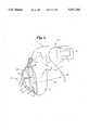
- FIG. 1illustrates an implantable defibrillator 10 and associated components connected to a heart 12.
- the implantable defibrillator 10includes a can 14, which is an electrode, a physician-programmable computer 16, including a memory 17 for storing programmable waveform information, a lead 18 connecting a patch electrode 20 to the implantable defibrillator 10, and a lead 22 having second electrodes connecting to the heart 12.
- Lead 22extends through the superior vena cava 24, the right atrium 26, and to the lower region of the right ventricle 28. Also illustrated are the left atrium 30 and the left ventricle 32.
- Sense electrodes 34 and 36are located at the distal end of the lead 22, and align in the lower region of the right atrium 26.
- the lead 22also includes shock electrodes 38 and 40.
- the shock electrode 38aligns in the upper portion of the right atrium 26 and a portion of the superior vena cava 24.
- Shock electrode 40aligns centrally in the right ventricle 28.
- FIGS. 2, 3, 4, and 5illustrate representative waveforms that can be formed by the physician-programmable computer 16 of FIG. 1.
- the formation of these waveformsis the subject matter of a patent entitled IMPLANTABLE DEFIBRILLATOR SYSTEM EMPLOYING CAPACITOR SWITCHING NETWORK, Ser. No. 07/704,619, filed May 23, 1991, now issued as U.S. Pat. No. 5,199,429 having the same assignee.
- FIGS. 2, 3, 4 and 5illustrate useful waveforms, it is appreciated that any other waveforms can also be incorporated within the teachings of the present invention.
- FIG. 2illustrates a truncated shock waveform 42 formed by two capacitors in series.
- FIG. 5illustrates a truncated shock waveform 48 formed by two capacitors sequential, truncated, polarity reversed, and series connected.
- any combination of shock waveformssuch as sequence incorporating a sequence of shock waveforms such as 42, 44, 46, 48. Even a shock waveform sequence where certain shock waveforms are repeated such as 42, 46, 46, 48 can be used. Any desirable sequence can be used whether only one type of waveform is sequentially repeated or whether two or more waveforms are repeated. Any combination or permutation of the sequences may be used as desired.
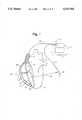
- FIGS. 6-8illustrate the principle of successive changeable pathways for detected and programmed delivery of simultaneous or delayed shock sequenced delivery to and about various areas of the heart.
- the physician-programmable computer 16detects fibrillation, and from that criteria decides within programmed limits and parameters as set by a physician where and when to deliver defibrillation shocks. All numerals in FIGS. 6-19 correspond to those elements previously described.
- Shock waveforms sent directly to, from or through a heart area to a defibrillator componentare indicated by a path arrow having a solid shaft, such as arrow 50 in FIG. 6.
- Shock waveforms which are delayedare represented by a path arrow having a dashed shaft such as arrow 52 in FIG. 6.
- the shock waveforms which are sentare those shock waves such as described in FIGS. 2, 3, 4 and 5. Again, any of the shock waveforms such as waveforms 42-48 can be incorporated and sent directly or delayed across any of the paths whether the path is a directly-sent path or a time-delay path.
- the shock wavesemanate from the shock electrode 40 in the right ventricle 28 in FIGS. 6-19, and travel through ports of the heart to either shock electrode 38, can electrode 14, or patch electrode 20.
- FIG. 6illustrates directly sent shock waveform path 50 traveling through the right ventricle 28 to the patch electrode 20, and delayed shock waveform paths 52 and 54 traveling from the right ventricle 28 to the can electrode 14 and to the shock electrode 38 in the superior vena cava 24.
- FIG. 7illustrates a directly sent shock waveform path 56 traveling through right ventricle 28 to the patch electrode 20 where the can electrode 14 is off.
- FIG. 8illustrates directly sent shock waveform paths 58 and 60 traveling, respectively, through the right ventricle 28, to the patch electrode 20 and the can electrode 14, and a delayed shock waveform path 62 traveling from the right ventricle 28, to the electrode 38 in the superior vena cava 24.
- FIG. 9illustrates a directly sent waveform path 64 traveling through the right ventricle 28, to the patch electrode 20, and a delayed shock waveform path 66 traveling from the right ventricle 28, to the can electrode 14.
- the shock electrode 38is not connected.
- FIG. 10illustrates directly sent waveform paths 68 and 70 traveling, respectively, through the right ventricle 28, to the patch electrode 20, and to the can electrode 14.
- the shock electrode 38is not connected.
- FIG. 11illustrates directly sent waveform paths 72, 74 and 76 traveling, respectively, through the right ventricle 28, to the patch electrode 20, to the can electrode 14, and to the electrode 38 in the superior vena cava 24.
- FIG. 12illustrates directly sent waveforms paths 78 and 80 traveling, respectively, through the right ventricle 28, to the can electrode 14 and to the superior vena cava 24.
- the patch electrodeis not connected.
- FIG. 13illustrates a delayed shock waveform path 82 traveling through the right ventricle 28, to the can electrode 14, and a directly sent wave path 84 traveling from the right ventricle 28, to the electrode 38 in the superior vena cava 24.
- the patch electrode 20is not connected.
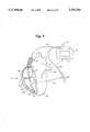
- FIG. 14illustrates a directly sent shock waveform path 86 traveling through the right ventricle 28, to the can electrode 14.
- the shock electrodes 38 and the patch electrode 20are not connected.
- FIG. 15illustrates a delayed shock waveform path 88 traveling through the right ventricle 28, to the patch electrode 20, and a directly sent shock waveform path 90 traveling through the right ventricle, to the can electrode 14.
- the shock electrode 38is not connected.
- FIG. 16illustrates delayed shock waveform paths 92 and 94 traveling, respectively, through the right ventricle 28, to the patch electrode 20, and the can electrode 14, and a directly sent shock wave path 96 traveling through the right ventricle 28, to the electrode 38 in the superior vena cava 24.
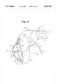
- FIG. 17illustrates a delayed shock waveform path 98 traveling through the right ventricle 28, to the patch electrode 20, and directly sent shock waveform paths 100 and 102 traveling, respectively, through the right ventricle 28, to the can electrode 14 and the electrode 38 in the superior vena cava 24.
- FIG. 18illustrates a directly sent waveform path 110 traveling through the right ventricle 28, to the patch electrode 20, and a delayed shock waveform path 112 traveling through the right ventricle, to the electrode 38 in the superior vena cava 24.
- the patch electrode 20is not connected.
- Table 1sets forth the atrial area, the sub Q patch, the can and the corresponding figure.
- the pulseis either a monophasic pulse or biphasic pulse.
Landscapes
- Health & Medical Sciences (AREA)
- Cardiology (AREA)
- Heart & Thoracic Surgery (AREA)
- Engineering & Computer Science (AREA)
- Biomedical Technology (AREA)
- Nuclear Medicine, Radiotherapy & Molecular Imaging (AREA)
- Radiology & Medical Imaging (AREA)
- Life Sciences & Earth Sciences (AREA)
- Animal Behavior & Ethology (AREA)
- General Health & Medical Sciences (AREA)
- Public Health (AREA)
- Veterinary Medicine (AREA)
- Electrotherapy Devices (AREA)
Abstract
Description
This is a Continuation of Ser. No. 08/856,982, now abandoned, filed Mar. 24, 1992.
1. Field of the Invention
The present invention pertains to the field of heart defibrillators, and more particularly, relates to delivery of programmable and sequenced waveforms to areas of the heart by the components of a defibrillator.
2. Description of the Prior Art
Prior art defibrillators deliver a number of successive shocks for heart defibrillation. The same waveform in these devices is repeated in succession usually to deliver four shock waveforms. The particular handicap or drawback with these devices is that the repeated similar waveforms are determined by the manufacturer, and cannot be changed unless a reimplant of the device is accomplished. The prior art devices used only a repeated similar waveform instead of waveforms of different magnitudes and shapes to accomplish the defibrillation process.
The present invention overcomes the inadequacies of the prior art by providing a programmable defibrillator which can deliver shock waveforms of different shapes and magnitude in different combinations of sequences which are field programmable by a physician.
Once an implantable defibrillator has determined that the heart is in fibrillation, it begins a sequence of activities that involve charging the output capacitors and verifying that fibrillation is still present before delivering the first shock pulse. After a shock pulse is delivered, the device continues to monitor the heart rate, and if it determines that the shock was unsuccessful in terminating the fibrillation, the implanted defibrillator will deliver a second shock, at the same or higher energy. This sequence can be repeated several times up to four times in currently available devices, after which the device terminates further attempts at conversion. The rationale for terminating therapy after four shocks is that further attempts are unlikely to be successful in that conversion thresholds tend to increase with time in a fibrillation episode, and after fibrillating for long periods, the patient is likely to have suffered irreversible brain damage. In addition, if the shocks are being delivered inappropriately due to noise on the leads or component failure, the patient will receive no more than four unnecessary shocks. The device resets itself after the heart rate has slowed to a normal level for a prescribed length of time.
There is considerable evidence in the literature that some shock waveforms have generally lower defibrillation thresholds than others. However, there are many exceptions to the general rule and for any given patient and/or for different electrode configurations, the most efficient shock waveform may not be the one installed in the implanted prior art device.
The general purpose of this implantable defibrillator is that the shock waveform is programmable so that the implanting physician can select the waveform that yields the lowest threshold for a given patient and electrode configuration.
Further, the invented implantable defibrillator allows the physician to program the device such that each successive shock waveform may be programmed independently. The rationale is that if the first and earliest shock failed, it would be better to try a new waveform on the next shock rather than to repeat a shock waveform that has just demonstrated failure to defibrillate.
According to one embodiment of the present invention, there is provided an implantable defibrillator including a patch electrode for application to the heart, and another lead having sensing electrodes and defibrillation electrodes which are aligned in the right atrium and the right ventricle. A physician-programmable computer, including a memory for storing programmable waveform information, is included in the can of the defibrillator.
One significant aspect and feature of the present invention is a defibrillator which is physician programmable.
Another significant aspect and feature of the present invention is a defibrillator which has a variety of waveforms which can be sequentially applied in the defibrillation process.
A further significant aspect and feature of the present invention is the selective steering of desired waveforms through the heart to the components of the defibrillator.
Still another significant aspect and feature of the present invention is time-sequenced delays of waveform application.
Having thus described one embodiment of the present invention, it is the principal object hereof to provide a programmable defibrillation for the delivery of sequenced, independently shaped and time-sequenced defibrillation shock waveforms to the human heart.
Other objects of the present invention and many of the attendant advantages of the present invention will be readily appreciated as the same becomes better understood by reference to the following detailed description when considered in connection with the accompanying drawings, in which like reference numerals designate like parts throughout the figures thereof and wherein:
FIG. 1 illustrates an implantable programmable defibrillator, the present invention, connected to a heart;
FIG. 2 illustrates a representative waveform;
FIG. 3 illustrates another representative waveform;
FIG. 4 illustrates another representative waveform;
FIG. 5 illustrates another representative waveform;
FIG. 6 illustrates shock waveform paths from the heart to the implantable programmable defibrillator;
FIG. 7 illustrates another set of waveform paths from the heart to the implantable programmable defibrillator;
FIG. 8 illustrates another set of waveform paths from the heart to the implantable programmable defibrillator;
FIG. 9 illustrates another set of waveform paths from the heart to the implantable programmable defibrillator;
FIG. 10 illustrates another set of waveform paths from the heart to the implantable programmable defibrillator;
FIG. 11 illustrates another set of waveform paths from the heart to the implantable programmable defibrillator;
FIG. 12 illustrates another set of waveform paths from the heart to the implantable programmable defibrillator;
FIG. 13 illustrates another set of waveform paths from the heart to the implantable programmable defibrillator;
FIG. 14 illustrates another set of waveform paths from the heart to the implantable programmable defibrillator;
FIG. 15 illustrates another set of waveform paths from the heart to the implantable programmable defibrillator;
FIG. 16 illustrates another set of waveform paths from the heart to the Implantable programmable defibrillator;
FIG. 17 illustrates another set of waveform paths from the heart to the implantable programmable defibrillator;
FIG. 18 illustrates another set of waveform paths from the heart to the implantable programmable defibrillator.
FIG. 1 illustrates animplantable defibrillator 10 and associated components connected to aheart 12. Theimplantable defibrillator 10 includes acan 14, which is an electrode, a physician-programmable computer 16, including amemory 17 for storing programmable waveform information, alead 18 connecting apatch electrode 20 to theimplantable defibrillator 10, and alead 22 having second electrodes connecting to theheart 12.Lead 22 extends through thesuperior vena cava 24, theright atrium 26, and to the lower region of theright ventricle 28. Also illustrated are theleft atrium 30 and theleft ventricle 32.Sense electrodes lead 22, and align in the lower region of theright atrium 26. Thelead 22 also includesshock electrodes shock electrode 38 aligns in the upper portion of theright atrium 26 and a portion of thesuperior vena cava 24.Shock electrode 40 aligns centrally in theright ventricle 28.
FIGS. 2, 3, 4, and 5 illustrate representative waveforms that can be formed by the physician-programmable computer 16 of FIG. 1. The formation of these waveforms is the subject matter of a patent entitled IMPLANTABLE DEFIBRILLATOR SYSTEM EMPLOYING CAPACITOR SWITCHING NETWORK, Ser. No. 07/704,619, filed May 23, 1991, now issued as U.S. Pat. No. 5,199,429 having the same assignee. Although FIGS. 2, 3, 4 and 5 illustrate useful waveforms, it is appreciated that any other waveforms can also be incorporated within the teachings of the present invention.
FIG. 2 illustrates atruncated shock waveform 42 formed by two capacitors in series.
FIG. 3 illustrates atruncated shock waveform 44 formed by two capacitors in series and having the polarity reversed.
FIG. 4 illustrates atruncated shock waveform 46 formed by two capacitors in parallel, and have the polarity reversed and series connected.
FIG. 5 illustrates atruncated shock waveform 48 formed by two capacitors sequential, truncated, polarity reversed, and series connected.
The waveforms 42-48 illustrated in FIGS. 2-5 can be programmed to be delivered as shock waves in almost any number of sequential arrangements such as four identical sequential shock waveforms such as four successive applications oftruncated shock waveform 42, or four sequentialtruncated shock waveform 44 and following in the same sequential pattern application for identicaltruncated shock waveforms
In the alternative, any combination of shock waveforms, such as sequence incorporating a sequence of shock waveforms such as 42, 44, 46, 48. Even a shock waveform sequence where certain shock waveforms are repeated such as 42, 46, 46, 48 can be used. Any desirable sequence can be used whether only one type of waveform is sequentially repeated or whether two or more waveforms are repeated. Any combination or permutation of the sequences may be used as desired.
FIGS. 6-8 illustrate the principle of successive changeable pathways for detected and programmed delivery of simultaneous or delayed shock sequenced delivery to and about various areas of the heart. The physician-programmable computer 16 detects fibrillation, and from that criteria decides within programmed limits and parameters as set by a physician where and when to deliver defibrillation shocks. All numerals in FIGS. 6-19 correspond to those elements previously described. Shock waveforms sent directly to, from or through a heart area to a defibrillator component are indicated by a path arrow having a solid shaft, such asarrow 50 in FIG. 6. Shock waveforms which are delayed are represented by a path arrow having a dashed shaft such asarrow 52 in FIG. 6. The shock waveforms which are sent are those shock waves such as described in FIGS. 2, 3, 4 and 5. Again, any of the shock waveforms such as waveforms 42-48 can be incorporated and sent directly or delayed across any of the paths whether the path is a directly-sent path or a time-delay path. The shock waves emanate from theshock electrode 40 in theright ventricle 28 in FIGS. 6-19, and travel through ports of the heart to eithershock electrode 38, can electrode 14, orpatch electrode 20.
FIG. 6 illustrates directly sentshock waveform path 50 traveling through theright ventricle 28 to thepatch electrode 20, and delayedshock waveform paths right ventricle 28 to thecan electrode 14 and to theshock electrode 38 in thesuperior vena cava 24.
FIG. 7 illustrates a directly sentshock waveform path 56 traveling throughright ventricle 28 to thepatch electrode 20 where thecan electrode 14 is off.
FIG. 8 illustrates directly sentshock waveform paths right ventricle 28, to thepatch electrode 20 and thecan electrode 14, and a delayedshock waveform path 62 traveling from theright ventricle 28, to theelectrode 38 in thesuperior vena cava 24.
FIG. 9 illustrates a directly sentwaveform path 64 traveling through theright ventricle 28, to thepatch electrode 20, and a delayedshock waveform path 66 traveling from theright ventricle 28, to thecan electrode 14. Theshock electrode 38 is not connected.
FIG. 10 illustrates directly sentwaveform paths right ventricle 28, to thepatch electrode 20, and to thecan electrode 14. Theshock electrode 38 is not connected.
FIG. 11 illustrates directly sentwaveform paths right ventricle 28, to thepatch electrode 20, to thecan electrode 14, and to theelectrode 38 in thesuperior vena cava 24.
FIG. 12 illustrates directly sentwaveforms paths right ventricle 28, to thecan electrode 14 and to thesuperior vena cava 24. The patch electrode is not connected.
FIG. 13 illustrates a delayedshock waveform path 82 traveling through theright ventricle 28, to thecan electrode 14, and a directly sentwave path 84 traveling from theright ventricle 28, to theelectrode 38 in thesuperior vena cava 24. Thepatch electrode 20 is not connected.
FIG. 14 illustrates a directly sentshock waveform path 86 traveling through theright ventricle 28, to thecan electrode 14. Theshock electrodes 38 and thepatch electrode 20 are not connected.
FIG. 15 illustrates a delayedshock waveform path 88 traveling through theright ventricle 28, to thepatch electrode 20, and a directly sentshock waveform path 90 traveling through the right ventricle, to thecan electrode 14. Theshock electrode 38 is not connected.
FIG. 16 illustrates delayedshock waveform paths right ventricle 28, to thepatch electrode 20, and thecan electrode 14, and a directly sentshock wave path 96 traveling through theright ventricle 28, to theelectrode 38 in thesuperior vena cava 24.
FIG. 17 illustrates a delayedshock waveform path 98 traveling through theright ventricle 28, to thepatch electrode 20, and directly sentshock waveform paths right ventricle 28, to thecan electrode 14 and theelectrode 38 in thesuperior vena cava 24.
FIG. 18 illustrates a directly sentwaveform path 110 traveling through theright ventricle 28, to thepatch electrode 20, and a delayedshock waveform path 112 traveling through the right ventricle, to theelectrode 38 in thesuperior vena cava 24. Thepatch electrode 20 is not connected.
TABLE 1 ______________________________________ Atrial area (SVC etc.) SubQ patch Can FIG ______________________________________ delayed direct (full) delayed 6 zero direct (full) zero 7 delayed direct (full) direct (full) 8 zero direct (full) delayed 9 zero direct (full) direct (full) 10 direct (full) direct (full) direct (full) 11 direct (full) zero direct (full) 12 direct (full) zero delayed 13 zero zero direct (full) 14 zero delayed direct (full) 15 direct (full) delayed delayed 16 direct (full) delayed direct (full) 17 delayed zero direct (full) 18 zero direct (full) zero Not shown delayed direct (full) zero Not shown direct (full) zero zero Not shown direct (full) delayed zero Not shown direct (full) direct (full) zero Not shown direct (full) direct (full) delayed Not shown delayed delayed direct (full) Not shown ______________________________________
Table 1 sets forth the atrial area, the sub Q patch, the can and the corresponding figure. The pulse is either a monophasic pulse or biphasic pulse.
Various modifications can be made to the present invention without departing from the apparent scope hereof.
Claims (6)
1. An improved implantable defibrillator system adapted to be implanted in a human patient for producing a capacitive-discharge countershock, the implantable defibrillator system being a self-contained device including a capacitor system, a battery system, a switching system and a sensing system all of which are connected to and controlled by a programmable computer system having a memory for storing a plurality of physician programmable charging voltage parameters, one parameter for each countershock in a sequence of countershocks to be delivered to the human patient as part of a multiple-countershock therapy regimen, and computer programming stored in the memory and executing in the computer system that, in response to an initial cardiac arrhythmia in the human patient sensed by the sensing system, selectively charges the capacitor system from the battery system in accordance with a first of the charging voltage parameters stored in the memory for the multiple-countershock therapy regimen and then selectively discharges the capacitor system as a first of the sequence of multiple countershocks delivered through the switching system to a plurality of electrodes adapted to be implanted in the human patient, after which, in response to a continuing cardiac arrhythmia in the human patient sensed by the sensing system, selectively charges the capacitor system from the battery system in accordance with a second of the charging voltage parameters stored in the memory for the multiple-countershock therapy regimen and then selectively discharges the capacitor system as a second of the sequence of multiple countershocks, the improvement comprising:
a data structure located in the memory for defining a plurality of different possible waveforms and a plurality of different possible wavepaths for individual countershocks in the multiple-countershock therapy regimen by storing a plurality of sets of physician programmable waveform parameters in the data structure, a unique set of waveform parameters being associated with each countershock in the sequence of multiple countershocks, the waveform parameters including both wave phase information and wave path information such that each set of waveform parameters defines a selected one of the different possible waveforms and defines a selected one of the different possible wave paths definable in the data structure; and
computer programming stored in the memory and executing in the computer system that selectively charges and then discharges the capacitor system in accordance with a first one of the unique sets of waveform parameters stored in the data structure as a first countershock in the sequence of multiple countershocks and, in response to a continuing cardiac arrhythmia in the human patient sensed by the sensing system, selectively charges and discharges the capacitor system in accordance with a subsequent one of the unique sets of waveform parameters stored in the data structure as a subsequent countershock in the sequence of multiple countershocks,
such that the first and subsequent countershocks delivered by the implantable defibrillator system as part of the sequence of multiple countershocks can be independently programmed for different waveforms and wave paths.
2. An improved method of operating an implantable defibrillator system adapted to be implanted in a human patient for producing a capacitive-discharge countershock, the implantable defibrillator system being a self-contained device electrically connected to a plurality of electrodes adapted to be implanted in the human patient, the device including a capacitor system, a battery system, a switching system and a sensing system all of which are connected to and controlled by a programmable computer system having a memory and computer programming stored in the memory and executing in the computer system that performs the computer-implemented steps of:
(a) using the sensing system to sense a cardiac arrhythmia in the human patient;
(b) in response to the cardiac arrhythmia, selectively charging the capacitor system from the battery system in accordance with a first of a plurality of physician programmable charging voltage parameters stored in the memory for a first of a sequence of multiple countershocks;
(c) selectively discharging the capacitor system as the first of the sequence of multiple countershocks delivered through the switching system to the plurality of electrodes in accordance with a single set of physician programmable waveform parameters stored in the memory,
(d) using the sensing system to sense if the cardiac arrhythmia in the human patient has been converted;
(e) if the cardiac arrhythmia has not been converted, selectively charging the capacitor system from the battery system in accordance with a subsequent one of the plurality of physician programmable charging voltage parameters stored in the memory for a subsequent one of the sequence of multiple countershocks;
(f) selectively discharging the capacitor system as a subsequent one of the sequence of multiple countershocks delivered through the switching system to the plurality of electrodes in accordance with the same single set of physician programmable waveform parameters stored in the memory for the first of the sequence of multiple countershocks; and
(g) repeating steps (d)-(f) for other subsequent ones of the multiple countershocks until the cardiac arrhythmia has been converted or the entire sequence of multiple countershocks has been delivered,
wherein the improved method comprises implemented steps of:
storing in a data structure defined in the memory a plurality of sets of physician programmable waveform parameters, a unique set of waveform parameters for each countershock in the sequence of multiple countershocks, the waveform parameters including both wave phase information and wave path information such that each set of waveform parameters defines a selected one of a plurality of different possible waveforms and defines a selected one of a plurality of different possible wave paths definable in the data structure; and
selectively discharging the capacitor system in step (c) in accordance with a first one of the unique sets of waveform parameters stored in the data structure, and selectively discharging the capacitor system in step (f) in accordance with a subsequent one of the unique sets of waveform parameters stored in the data structure for each subsequent countershock in the sequence of multiple countershocks,
such that the first and subsequent countershocks delivered by the implantable defibrillator system as part of the sequence of multiple countershocks can be independently programmed for different waveforms and wave paths.
3. A method of operating an implantable cardioverter defibrillator system adapted to be implanted in a patient for delivering a sequence of capacitive-discharge countershocks to the heart of the patient as part of a multiple-countershock therapy regimen for treating a continuing cardiac arrhythmia in the patient, the implantable defibrillator system having a sensing system, a battery system and a capacitor system, all of which are connected to and controlled by a programmable computer having a memory, the method comprising the steps of:
(a) programming a first set of waveform parameters in the memory in the programmable computer to define a first countershock in the sequence of multiple countershocks, the first countershock having a waveform that is individually selected and programmed by a physician;
(b) programming at least one set additional set of waveform parameters in the memory in the programmable computer to define at least one subsequent countershock in the sequence of multiple countershocks, the subsequent countershock having a waveform that is independent of the waveform of the first countershock and that is individually selected and programmed by the physician;
(c) using the sensing system to sense a cardiac arrhythmia in the patient;
(d) in response to a cardiac arrhythmia, using the battery system to charge the capacitor system to delivery a first countershock to the patient;
(e) discharging the capacitor system in accordance with the first set of waveform parameters stored in the memory programmed in step (a) to deliver the first countershock to the patient;
(f) sensing whether the cardiac arrhythmia in the patient has been converted;
(g) if the cardiac arrhythmia has not been converted, using the battery system to recharge the capacitor system to deliver a subsequent countershock to the patient;
(h) discharging the capacitor system in accordance with a subsequent set of waveform parameters stored in the memory programmed in step (b) to deliver a subsequent countershock to the patient, the subsequent countershock having a waveform that is independent of the waveform of at least one other countershock in the sequence of multiple countershocks and that is individually programmed in step (b); and
(i) repeating steps (f)-(h) until the cardiac arrhythmia has been converted or the entire sequence of multiple countershocks has been delivered.
4. The method of claim 3, wherein:
step (a) further includes programming the memory in the programmable computer to define the set of waveform parameters for the first countershock as having a first wave path;
step (b) further includes programming the memory in the programmable computer to define the set of waveform parameters for a subsequent countershock as having a wave path that is independent of the wave path of at least one other countershock in the sequence of multiple countershocks;
step (e) further includes discharging the capacitor system in accordance with the first set of waveform parameters programmed in step (a) to deliver the first countershock having the wave path individually programmed in step (a); and
step (h) further includes discharging the capacitor system in accordance with the subsequent sets of waveform parameters programmed in step (b) to deliver a subsequent countershock having a wave path that is independent of the wave path of at least one other countershock in the sequence of multiple countershocks and that is individually programmed in step (b).
5. A self-contained implantable defibrillator system adapted to be implanted in a patient for producing a sequence of multiple capacitive-discharge countershocks to the heart of the patient as part of a multiple-countershock therapy regimen for treating a continuing cardiac arrhythmia in the patient, the system comprising:
a countershock delivery system for delivering the sequence of multiple countershocks to the patient, the countershock delivery system including a capacitor system and a battery system coupled with the capacitor system to charge the capacitor system;
a sensing system to detect a cardiac arrhythmia in the patient;
a programmable computer means, coupled with the countershock delivery system and with the sensing system, the programmable computer means including:
means for storing data defining the waveform of each countershock independently, such that each delivered countershock can be programmed to have a waveform different than and independent of the waveform of any other countershock in the sequence of multiple countershocks; and
means for directing delivery of each countershock in the sequence of multiple countershocks through the countershock delivery system in accordance with detection of a cardiac arrhythmia by the sensing system; and
means for delaying delivery of each subsequent countershock after the first countershock in the sequence of multiple countershocks until the sensing system detects if the cardiac arrhythmia in the patient has been converted in response to a previous countershock and the battery system has charged the capacitor system for delivery of the subsequent countershock.
6. The defibrillator system of claim 5, wherein the programmable computer means further comprises means for storing data defining the wave path of each countershock independently, such that each delivered countershock can be programmed to have a wave path different than and independent of the wave path of any other countershock in the sequence of multiple countershocks.
Priority Applications (1)
| Application Number | Priority Date | Filing Date | Title |
|---|---|---|---|
| US08/227,563US5531764A (en) | 1992-03-24 | 1994-04-14 | Implantable defibrillator system and method having successive changeable defibrillation waveforms |
Applications Claiming Priority (2)
| Application Number | Priority Date | Filing Date | Title |
|---|---|---|---|
| US85698292A | 1992-03-24 | 1992-03-24 | |
| US08/227,563US5531764A (en) | 1992-03-24 | 1994-04-14 | Implantable defibrillator system and method having successive changeable defibrillation waveforms |
Related Parent Applications (1)
| Application Number | Title | Priority Date | Filing Date |
|---|---|---|---|
| US85698292AContinuation | 1992-03-24 | 1992-03-24 |
Publications (1)
| Publication Number | Publication Date |
|---|---|
| US5531764Atrue US5531764A (en) | 1996-07-02 |
Family
ID=25324889
Family Applications (1)
| Application Number | Title | Priority Date | Filing Date |
|---|---|---|---|
| US08/227,563Expired - LifetimeUS5531764A (en) | 1992-03-24 | 1994-04-14 | Implantable defibrillator system and method having successive changeable defibrillation waveforms |
Country Status (1)
| Country | Link |
|---|---|
| US (1) | US5531764A (en) |
Cited By (74)
| Publication number | Priority date | Publication date | Assignee | Title |
|---|---|---|---|---|
| US5718718A (en)* | 1993-09-13 | 1998-02-17 | Angeion Corporation | Method and apparatus for polarity reversal of consecutive defibrillation countershocks having back biasing precharge pulses |
| US5725560A (en)* | 1996-06-20 | 1998-03-10 | Hewlett-Packard Company | Defibrillator with waveform selection circuitry |
| US5800465A (en)* | 1996-06-18 | 1998-09-01 | Medtronic, Inc. | System and method for multisite steering of cardiac stimuli |
| WO2000004947A2 (en) | 1998-07-20 | 2000-02-03 | Impulse Dynamics N.V. | Pacing with hemodynamic enhancement |
| US6152882A (en)* | 1999-01-26 | 2000-11-28 | Impulse Dynamics N.V. | Apparatus and method for chronic measurement of monophasic action potentials |
| EP0973582A4 (en)* | 1996-12-18 | 2001-02-07 | Zmd Corp | Electrotherapy current waveform |
| US6208896B1 (en) | 1998-11-13 | 2001-03-27 | Agilent Technologies, Inc. | Method and apparatus for providing variable defibrillation waveforms using switch-mode amplification |
| US20020042634A1 (en)* | 2000-09-18 | 2002-04-11 | Cameron Health, Inc. | Ceramics and/or other material insulated shell for active and non-active S-ICD can |
| US20020052632A1 (en)* | 1996-01-08 | 2002-05-02 | Shlomo Ben-Haim | Electrical muscle controller |
| US6424866B2 (en) | 1999-03-25 | 2002-07-23 | Impulse Dynamics N.V. | Apparatus and method for timing the delivery of non-excitatory ETC signals to a heart |
| US6449506B1 (en)* | 1999-06-25 | 2002-09-10 | Biontronik Mess-Und Therapiegeraete Gmbh & Co. Ingenieubuero Berlin | Multiphase defibrillator with conductive housing |
| US6456876B1 (en) | 2000-02-28 | 2002-09-24 | Pacesetter, Inc. | Dual-chamber implantable cardiac stimulation system and device with selectable arrhythmia termination electrode configurations and method |
| US6459928B2 (en) | 1999-06-08 | 2002-10-01 | Impulse Dynamics N.V. | Apparatus and method for collecting data useful for determining the parameters of an alert window for timing delivery or ETC signals to a heart under varying cardiac conditions |
| US6484057B2 (en) | 2000-12-21 | 2002-11-19 | Uab Research Foundation | Pacing methods and devices for treating cardiac arrhythmias and fibrillation |
| US20030055460A1 (en)* | 1997-03-07 | 2003-03-20 | Owen James M. | Defibrillator with configurable capacitor arrangement |
| US6597952B1 (en) | 1999-06-08 | 2003-07-22 | Impulse Dynamics N. V. | Apparatus and method for setting the parameters of an alert window used for timing the delivery of ETC signals to a heart under varying cardiac conditions |
| US20030208236A1 (en)* | 2002-05-06 | 2003-11-06 | Cardiac Pacemakers, Inc. | System and method for providing temporary stimulation therapy to optimize chronic electrical performance for electrodes used in conjunction with a cardiac rhythm management system |
| US20040024421A1 (en)* | 2002-07-31 | 2004-02-05 | Ideker Raymond E. | Pacing methods and devices using feedback controlled timing |
| US20040049232A1 (en)* | 2002-09-10 | 2004-03-11 | Ideker Raymond E. | Post-defibrillation pacing methods and devices |
| US20040049117A1 (en)* | 2002-09-10 | 2004-03-11 | Ideker Raymond E. | Devices for detecting the presence of cardiac activity following administration of defibrillation therapy |
| US20040049118A1 (en)* | 2002-09-10 | 2004-03-11 | Ideker Raymond E. | Methods, systems and computer program products for treating fibrillation in a patient based on the presence of fibrillation following administration of defibrillation therapy |
| US6721598B1 (en) | 2001-08-31 | 2004-04-13 | Pacesetter, Inc. | Coronary sinus cardiac lead for stimulating and sensing in the right and left heart and system |
| US20040073261A1 (en)* | 2002-10-09 | 2004-04-15 | Kroll Mark W. | Methods and systems for treating ventricular fibrillation |
| US6735472B2 (en)* | 2001-01-26 | 2004-05-11 | Pacesetter, Inc. | Method of defibrillating a heart with electrode configurations including a left ventricular defibrillation electrode |
| US6745081B1 (en) | 2001-08-31 | 2004-06-01 | Pacesetter, Inc. | Coronary Sinus Cardiac Lead For Stimulating and Sensing The Atria of the Right and Left Heart and System |
| US6748277B1 (en) | 2001-10-11 | 2004-06-08 | Pacesetter, Inc. | Medical catheter/lead body design and means of manufacture thereof |
| US6748268B1 (en) | 2001-08-31 | 2004-06-08 | Pacesetter, Inc. | Three lead universal pacing and shocking system |
| US6760619B1 (en) | 2001-08-31 | 2004-07-06 | Pacesetter, Inc. | Two lead universal defibrillation, pacing and sensing system |
| US20040138710A1 (en)* | 1996-01-11 | 2004-07-15 | Itsik Shemer | Signal delivery through the right ventricular septum |
| US20040243190A1 (en)* | 1996-01-08 | 2004-12-02 | Shlomo Ben-Haim | Electrical muscle controller |
| US6987999B1 (en) | 2002-05-02 | 2006-01-17 | Pacesetter, Inc. | Implantable defibrillator with alternating counter electrode |
| US20060069326A1 (en)* | 2004-09-24 | 2006-03-30 | Roger Lee Heath | Resuscitation and life support system, method and apparatus |
| US7027863B1 (en) | 1999-10-25 | 2006-04-11 | Impulse Dynamics N.V. | Device for cardiac therapy |
| US20060155334A1 (en)* | 2003-03-13 | 2006-07-13 | Ideker Raymond E | Methods and systems for reducing discomfort from cardiac defibrillation shocks |
| US20060212079A1 (en)* | 1999-10-25 | 2006-09-21 | Routh Andre G | Cardiac contractility modulation device having anti-arrhythmic capabilities and method of operating thereof |
| US7130682B2 (en) | 2000-12-26 | 2006-10-31 | Cardiac Pacemakers, Inc. | Pacing and sensing vectors |
| US20070027490A1 (en)* | 1996-09-16 | 2007-02-01 | Shlomo Ben-Haim | Fencing of Cardiac Muscles |
| US20070060956A1 (en)* | 2005-09-09 | 2007-03-15 | Nassif Rabih C | Method and apparatus for variable capacitance defibrillation |
| WO2006058028A3 (en)* | 2004-11-22 | 2007-04-05 | Gentcorp Ltd | High-energy battery power source for implantable medical use |
| US20070203556A1 (en)* | 2006-02-28 | 2007-08-30 | Rutten Jean J G | Subcutaneous lead fixation mechanisms |
| US7283871B1 (en) | 2005-04-07 | 2007-10-16 | Pacesetter, Inc. | Self adjusting optimal waveforms |
| US20080037033A1 (en)* | 2004-06-14 | 2008-02-14 | Isra Vision Systems Ag | Sensor For Measuring The Surface Of An Object |
| US7398122B1 (en) | 2005-04-07 | 2008-07-08 | Pacesetter, Inc. | Self adjusting optimal waveforms |
| US20090254135A1 (en)* | 2008-04-08 | 2009-10-08 | Cardiac Pacemakers, Inc. | High-energy anti-tachycardia therapy |
| US7678573B2 (en) | 1999-02-04 | 2010-03-16 | Pluristem Ltd. | Method of preparing a conditioned medium from a confluent stromal cell culture |
| US7734344B2 (en) | 2003-12-02 | 2010-06-08 | Uab Research Foundation | Methods, systems and computer program products to inhibit ventricular fibrillation during cardiopulmonary resuscitation |
| US7840262B2 (en) | 2003-03-10 | 2010-11-23 | Impulse Dynamics Nv | Apparatus and method for delivering electrical signals to modify gene expression in cardiac tissue |
| US7840264B1 (en) | 1996-08-19 | 2010-11-23 | Mr3 Medical, Llc | System and method for breaking reentry circuits by cooling cardiac tissue |
| US7843439B2 (en) | 2003-02-10 | 2010-11-30 | N-Trig Ltd. | Touch detection for a digitizer |
| US7908003B1 (en) | 1996-08-19 | 2011-03-15 | Mr3 Medical Llc | System and method for treating ischemia by improving cardiac efficiency |
| US7953481B1 (en) | 1999-10-25 | 2011-05-31 | Impulse Dynamics N.V. | Anti-arrhythmic device and a method of delivering anti-arrhythmic cardiac therapy |
| US8019421B2 (en) | 1999-03-05 | 2011-09-13 | Metacure Limited | Blood glucose level control |
| US8244371B2 (en) | 2005-03-18 | 2012-08-14 | Metacure Limited | Pancreas lead |
| US8321013B2 (en) | 1996-01-08 | 2012-11-27 | Impulse Dynamics, N.V. | Electrical muscle controller and pacing with hemodynamic enhancement |
| US8346363B2 (en) | 1999-03-05 | 2013-01-01 | Metacure Limited | Blood glucose level control |
| US8352031B2 (en) | 2004-03-10 | 2013-01-08 | Impulse Dynamics Nv | Protein activity modification |
| US8548583B2 (en) | 2004-03-10 | 2013-10-01 | Impulse Dynamics Nv | Protein activity modification |
| US8666495B2 (en) | 1999-03-05 | 2014-03-04 | Metacure Limited | Gastrointestinal methods and apparatus for use in treating disorders and controlling blood sugar |
| US8700161B2 (en) | 1999-03-05 | 2014-04-15 | Metacure Limited | Blood glucose level control |
| US8706217B2 (en) | 2000-09-18 | 2014-04-22 | Cameron Health | Cardioverter-defibrillator having a focused shocking area and orientation thereof |
| US8792985B2 (en) | 2003-07-21 | 2014-07-29 | Metacure Limited | Gastrointestinal methods and apparatus for use in treating disorders and controlling blood sugar |
| US8825152B2 (en) | 1996-01-08 | 2014-09-02 | Impulse Dynamics, N.V. | Modulation of intracellular calcium concentration using non-excitatory electrical signals applied to the tissue |
| US8831720B2 (en) | 2000-09-18 | 2014-09-09 | Cameron Health, Inc. | Method of implanting and using a subcutaneous defibrillator |
| US8934975B2 (en) | 2010-02-01 | 2015-01-13 | Metacure Limited | Gastrointestinal electrical therapy |
| US9101765B2 (en) | 1999-03-05 | 2015-08-11 | Metacure Limited | Non-immediate effects of therapy |
| US9138589B2 (en) | 2001-11-21 | 2015-09-22 | Cameron Health, Inc. | Apparatus and method for identifying atrial arrhythmia by far-field sensing |
| US9144683B2 (en) | 2000-09-18 | 2015-09-29 | Cameron Health, Inc. | Post-shock treatment in a subcutaneous device |
| US9289618B1 (en) | 1996-01-08 | 2016-03-22 | Impulse Dynamics Nv | Electrical muscle controller |
| US9713723B2 (en) | 1996-01-11 | 2017-07-25 | Impulse Dynamics Nv | Signal delivery through the right ventricular septum |
| US9821158B2 (en) | 2005-02-17 | 2017-11-21 | Metacure Limited | Non-immediate effects of therapy |
| US9931503B2 (en) | 2003-03-10 | 2018-04-03 | Impulse Dynamics Nv | Protein activity modification |
| US10905884B2 (en) | 2012-07-20 | 2021-02-02 | Cardialen, Inc. | Multi-stage atrial cardioversion therapy leads |
| US11439815B2 (en) | 2003-03-10 | 2022-09-13 | Impulse Dynamics Nv | Protein activity modification |
| US11779768B2 (en) | 2004-03-10 | 2023-10-10 | Impulse Dynamics Nv | Protein activity modification |
Citations (12)
| Publication number | Priority date | Publication date | Assignee | Title |
|---|---|---|---|---|
| US4708145A (en)* | 1982-06-01 | 1987-11-24 | Medtronic, Inc. | Sequential-pulse, multiple pathway defibrillation method |
| US4727877A (en)* | 1984-12-18 | 1988-03-01 | Medtronic, Inc. | Method and apparatus for low energy endocardial defibrillation |
| EP0280526A2 (en)* | 1987-02-27 | 1988-08-31 | Intermedics, Inc. | Biphasic waveforms for defibrillation |
| US4800883A (en)* | 1986-04-02 | 1989-01-31 | Intermedics, Inc. | Apparatus for generating multiphasic defibrillation pulse waveform |
| US4830006A (en)* | 1986-06-17 | 1989-05-16 | Intermedics, Inc. | Implantable cardiac stimulator for detection and treatment of ventricular arrhythmias |
| US4850357A (en)* | 1988-01-12 | 1989-07-25 | Cardiac Pacemakers, Inc. | Biphasic pulse generator for an implantable defibrillator |
| US4953551A (en)* | 1987-01-14 | 1990-09-04 | Medtronic, Inc. | Method of defibrillating a heart |
| US5107834A (en)* | 1991-01-30 | 1992-04-28 | Cardiac Pacemakers, Inc. | Low energy multiple shock defibrillation/cardioversion discharge technique and electrode configuration |
| US5133353A (en)* | 1990-04-25 | 1992-07-28 | Cardiac Pacemakers, Inc. | Implantable intravenous cardiac stimulation system with pulse generator housing serving as optional additional electrode |
| US5163427A (en)* | 1990-11-14 | 1992-11-17 | Medtronic, Inc. | Apparatus for delivering single and multiple cardioversion and defibrillation pulses |
| US5184616A (en)* | 1991-10-21 | 1993-02-09 | Telectronics Pacing Systems, Inc. | Apparatus and method for generation of varying waveforms in arrhythmia control system |
| US5199429A (en)* | 1991-05-23 | 1993-04-06 | Angemed, Inc. | Implantable defibrillator system employing capacitor switching networks |
- 1994
- 1994-04-14USUS08/227,563patent/US5531764A/ennot_activeExpired - Lifetime
Patent Citations (14)
| Publication number | Priority date | Publication date | Assignee | Title |
|---|---|---|---|---|
| US4708145A (en)* | 1982-06-01 | 1987-11-24 | Medtronic, Inc. | Sequential-pulse, multiple pathway defibrillation method |
| US4727877A (en)* | 1984-12-18 | 1988-03-01 | Medtronic, Inc. | Method and apparatus for low energy endocardial defibrillation |
| US4800883A (en)* | 1986-04-02 | 1989-01-31 | Intermedics, Inc. | Apparatus for generating multiphasic defibrillation pulse waveform |
| US4830006B1 (en)* | 1986-06-17 | 1997-10-28 | Intermedics Inc | Implantable cardiac stimulator for detection and treatment of ventricular arrhythmias |
| US4830006A (en)* | 1986-06-17 | 1989-05-16 | Intermedics, Inc. | Implantable cardiac stimulator for detection and treatment of ventricular arrhythmias |
| US4953551A (en)* | 1987-01-14 | 1990-09-04 | Medtronic, Inc. | Method of defibrillating a heart |
| EP0280526A2 (en)* | 1987-02-27 | 1988-08-31 | Intermedics, Inc. | Biphasic waveforms for defibrillation |
| US4850357A (en)* | 1988-01-12 | 1989-07-25 | Cardiac Pacemakers, Inc. | Biphasic pulse generator for an implantable defibrillator |
| US5133353A (en)* | 1990-04-25 | 1992-07-28 | Cardiac Pacemakers, Inc. | Implantable intravenous cardiac stimulation system with pulse generator housing serving as optional additional electrode |
| US5385574A (en)* | 1990-04-25 | 1995-01-31 | Cardiac Pacemakers, Inc. | Implantable intravenous cardiac stimulation system with pulse generator housing serving as optional additional electrode |
| US5163427A (en)* | 1990-11-14 | 1992-11-17 | Medtronic, Inc. | Apparatus for delivering single and multiple cardioversion and defibrillation pulses |
| US5107834A (en)* | 1991-01-30 | 1992-04-28 | Cardiac Pacemakers, Inc. | Low energy multiple shock defibrillation/cardioversion discharge technique and electrode configuration |
| US5199429A (en)* | 1991-05-23 | 1993-04-06 | Angemed, Inc. | Implantable defibrillator system employing capacitor switching networks |
| US5184616A (en)* | 1991-10-21 | 1993-02-09 | Telectronics Pacing Systems, Inc. | Apparatus and method for generation of varying waveforms in arrhythmia control system |
Non-Patent Citations (6)
| Title |
|---|
| Medtronic R PCT TM Device Tachyarrhythima Control System Reference Guide Apr. 1992.* |
| MedtronicR PCTTM Device Tachyarrhythima Control System Reference Guide Apr. 1992. |
| Ventak R PRx TM 1700/1705 Physician s Manual, Cardiac Pacemarks, Inc.* |
| VentakR PRxTM 1700/1705 Physician's Manual, Cardiac Pacemarks, Inc. |
| Ventritex R Cadence R Tiered Therapy Defibrillator System Cadence Model V 100 and Cadence Programmer, Prel. Physician s Manual, Oct. 1990.* |
| VentritexR CadenceR Tiered Therapy Defibrillator System Cadence Model V-100 and Cadence Programmer, Prel. Physician's Manual, Oct. 1990. |
Cited By (117)
| Publication number | Priority date | Publication date | Assignee | Title |
|---|---|---|---|---|
| US5718718A (en)* | 1993-09-13 | 1998-02-17 | Angeion Corporation | Method and apparatus for polarity reversal of consecutive defibrillation countershocks having back biasing precharge pulses |
| US8825152B2 (en) | 1996-01-08 | 2014-09-02 | Impulse Dynamics, N.V. | Modulation of intracellular calcium concentration using non-excitatory electrical signals applied to the tissue |
| US20040243190A1 (en)* | 1996-01-08 | 2004-12-02 | Shlomo Ben-Haim | Electrical muscle controller |
| US7167748B2 (en) | 1996-01-08 | 2007-01-23 | Impulse Dynamics Nv | Electrical muscle controller |
| US7062318B2 (en) | 1996-01-08 | 2006-06-13 | Impulse Dynamics (Israel) Ltd | Electrical muscle controller |
| US9289618B1 (en) | 1996-01-08 | 2016-03-22 | Impulse Dynamics Nv | Electrical muscle controller |
| US20080058879A1 (en)* | 1996-01-08 | 2008-03-06 | Shlomo Ben-Haim | Electrical Muscle Controller |
| US8306616B2 (en) | 1996-01-08 | 2012-11-06 | Impulse Dynamics, N.V. | Electrical muscle controller |
| US20020052632A1 (en)* | 1996-01-08 | 2002-05-02 | Shlomo Ben-Haim | Electrical muscle controller |
| US8301247B2 (en) | 1996-01-08 | 2012-10-30 | Impulse Dynamics, N.V. | Electrical muscle controller |
| US8321013B2 (en) | 1996-01-08 | 2012-11-27 | Impulse Dynamics, N.V. | Electrical muscle controller and pacing with hemodynamic enhancement |
| US8311629B2 (en) | 1996-01-08 | 2012-11-13 | Impulse Dynamics, N.V. | Electrical muscle controller |
| US8306617B2 (en) | 1996-01-08 | 2012-11-06 | Impulse Dynamics N.V. | Electrical muscle controller |
| US8260416B2 (en) | 1996-01-08 | 2012-09-04 | Impulse Dynamics, N.V. | Electrical muscle controller |
| US7187970B2 (en) | 1996-01-11 | 2007-03-06 | Impulse Dynamics (Israel) Ltd | Excitable tissue control signal delivery to the right ventricular septum |
| US20040138710A1 (en)* | 1996-01-11 | 2004-07-15 | Itsik Shemer | Signal delivery through the right ventricular septum |
| US9713723B2 (en) | 1996-01-11 | 2017-07-25 | Impulse Dynamics Nv | Signal delivery through the right ventricular septum |
| US5800465A (en)* | 1996-06-18 | 1998-09-01 | Medtronic, Inc. | System and method for multisite steering of cardiac stimuli |
| US5725560A (en)* | 1996-06-20 | 1998-03-10 | Hewlett-Packard Company | Defibrillator with waveform selection circuitry |
| US7840264B1 (en) | 1996-08-19 | 2010-11-23 | Mr3 Medical, Llc | System and method for breaking reentry circuits by cooling cardiac tissue |
| US7908003B1 (en) | 1996-08-19 | 2011-03-15 | Mr3 Medical Llc | System and method for treating ischemia by improving cardiac efficiency |
| US20070027490A1 (en)* | 1996-09-16 | 2007-02-01 | Shlomo Ben-Haim | Fencing of Cardiac Muscles |
| EP0973582A4 (en)* | 1996-12-18 | 2001-02-07 | Zmd Corp | Electrotherapy current waveform |
| EP1535645A1 (en)* | 1996-12-18 | 2005-06-01 | Zmd Corporation | Electrotherapy current waveform |
| US20030055460A1 (en)* | 1997-03-07 | 2003-03-20 | Owen James M. | Defibrillator with configurable capacitor arrangement |
| US7460907B1 (en) | 1998-07-20 | 2008-12-02 | Impulse Dynamics N.V. | Pacing with hemodynamic enhancement |
| WO2000004947A2 (en) | 1998-07-20 | 2000-02-03 | Impulse Dynamics N.V. | Pacing with hemodynamic enhancement |
| US6208896B1 (en) | 1998-11-13 | 2001-03-27 | Agilent Technologies, Inc. | Method and apparatus for providing variable defibrillation waveforms using switch-mode amplification |
| US6152882A (en)* | 1999-01-26 | 2000-11-28 | Impulse Dynamics N.V. | Apparatus and method for chronic measurement of monophasic action potentials |
| US7678573B2 (en) | 1999-02-04 | 2010-03-16 | Pluristem Ltd. | Method of preparing a conditioned medium from a confluent stromal cell culture |
| US9101765B2 (en) | 1999-03-05 | 2015-08-11 | Metacure Limited | Non-immediate effects of therapy |
| US8666495B2 (en) | 1999-03-05 | 2014-03-04 | Metacure Limited | Gastrointestinal methods and apparatus for use in treating disorders and controlling blood sugar |
| US8700161B2 (en) | 1999-03-05 | 2014-04-15 | Metacure Limited | Blood glucose level control |
| US8019421B2 (en) | 1999-03-05 | 2011-09-13 | Metacure Limited | Blood glucose level control |
| US8346363B2 (en) | 1999-03-05 | 2013-01-01 | Metacure Limited | Blood glucose level control |
| US6424866B2 (en) | 1999-03-25 | 2002-07-23 | Impulse Dynamics N.V. | Apparatus and method for timing the delivery of non-excitatory ETC signals to a heart |
| US6459928B2 (en) | 1999-06-08 | 2002-10-01 | Impulse Dynamics N.V. | Apparatus and method for collecting data useful for determining the parameters of an alert window for timing delivery or ETC signals to a heart under varying cardiac conditions |
| US6597952B1 (en) | 1999-06-08 | 2003-07-22 | Impulse Dynamics N. V. | Apparatus and method for setting the parameters of an alert window used for timing the delivery of ETC signals to a heart under varying cardiac conditions |
| US6449506B1 (en)* | 1999-06-25 | 2002-09-10 | Biontronik Mess-Und Therapiegeraete Gmbh & Co. Ingenieubuero Berlin | Multiphase defibrillator with conductive housing |
| US7027863B1 (en) | 1999-10-25 | 2006-04-11 | Impulse Dynamics N.V. | Device for cardiac therapy |
| US7953481B1 (en) | 1999-10-25 | 2011-05-31 | Impulse Dynamics N.V. | Anti-arrhythmic device and a method of delivering anti-arrhythmic cardiac therapy |
| US20060212079A1 (en)* | 1999-10-25 | 2006-09-21 | Routh Andre G | Cardiac contractility modulation device having anti-arrhythmic capabilities and method of operating thereof |
| US7647102B2 (en) | 1999-10-25 | 2010-01-12 | Impulse Dynamics N.V. | Cardiac contractility modulation device having anti-arrhythmic capabilities and method of operating thereof |
| US7212859B1 (en) | 2000-02-28 | 2007-05-01 | Pacesetter, Inc. | Dual-chamber implantable cardiac stimulation system and device with selectable arrhythmia termination electrode configurations and method |
| US6456876B1 (en) | 2000-02-28 | 2002-09-24 | Pacesetter, Inc. | Dual-chamber implantable cardiac stimulation system and device with selectable arrhythmia termination electrode configurations and method |
| US20020042634A1 (en)* | 2000-09-18 | 2002-04-11 | Cameron Health, Inc. | Ceramics and/or other material insulated shell for active and non-active S-ICD can |
| US8706217B2 (en) | 2000-09-18 | 2014-04-22 | Cameron Health | Cardioverter-defibrillator having a focused shocking area and orientation thereof |
| US8831720B2 (en) | 2000-09-18 | 2014-09-09 | Cameron Health, Inc. | Method of implanting and using a subcutaneous defibrillator |
| US7039465B2 (en)* | 2000-09-18 | 2006-05-02 | Cameron Health, Inc. | Ceramics and/or other material insulated shell for active and non-active S-ICD can |
| US9144683B2 (en) | 2000-09-18 | 2015-09-29 | Cameron Health, Inc. | Post-shock treatment in a subcutaneous device |
| US6484057B2 (en) | 2000-12-21 | 2002-11-19 | Uab Research Foundation | Pacing methods and devices for treating cardiac arrhythmias and fibrillation |
| US7130682B2 (en) | 2000-12-26 | 2006-10-31 | Cardiac Pacemakers, Inc. | Pacing and sensing vectors |
| US6735472B2 (en)* | 2001-01-26 | 2004-05-11 | Pacesetter, Inc. | Method of defibrillating a heart with electrode configurations including a left ventricular defibrillation electrode |
| US20070055313A1 (en)* | 2001-02-08 | 2007-03-08 | Cardiac Pacemakers, Inc. | Pacing and sensing vectors |
| US9278221B2 (en) | 2001-02-08 | 2016-03-08 | Cardiac Pacemakers, Inc. | Pacing and sensing vectors |
| US7945325B2 (en) | 2001-02-08 | 2011-05-17 | Cardiac Pacemakers, Inc. | Pacing and sensing vectors |
| US8798744B2 (en) | 2001-02-08 | 2014-08-05 | Cardiac Pacemakers, Inc. | Pacing and sensing vectors |
| US20070049978A1 (en)* | 2001-02-08 | 2007-03-01 | Cardiac Pacemakers, Inc. | Pacing and sensing vectors |
| US7991468B2 (en) | 2001-02-08 | 2011-08-02 | Cardiac Pacemakers, Inc. | Pacing and sensing vectors |
| US6760619B1 (en) | 2001-08-31 | 2004-07-06 | Pacesetter, Inc. | Two lead universal defibrillation, pacing and sensing system |
| US6748268B1 (en) | 2001-08-31 | 2004-06-08 | Pacesetter, Inc. | Three lead universal pacing and shocking system |
| US6721598B1 (en) | 2001-08-31 | 2004-04-13 | Pacesetter, Inc. | Coronary sinus cardiac lead for stimulating and sensing in the right and left heart and system |
| US6745081B1 (en) | 2001-08-31 | 2004-06-01 | Pacesetter, Inc. | Coronary Sinus Cardiac Lead For Stimulating and Sensing The Atria of the Right and Left Heart and System |
| US6748277B1 (en) | 2001-10-11 | 2004-06-08 | Pacesetter, Inc. | Medical catheter/lead body design and means of manufacture thereof |
| US9522283B2 (en) | 2001-11-21 | 2016-12-20 | Cameron Health Inc. | Apparatus and method for identifying atrial arrhythmia by far-field sensing |
| US9993653B2 (en) | 2001-11-21 | 2018-06-12 | Cameron Health, Inc. | Apparatus and method for identifying atrial arrhythmia by far-field sensing |
| US9138589B2 (en) | 2001-11-21 | 2015-09-22 | Cameron Health, Inc. | Apparatus and method for identifying atrial arrhythmia by far-field sensing |
| US6987999B1 (en) | 2002-05-02 | 2006-01-17 | Pacesetter, Inc. | Implantable defibrillator with alternating counter electrode |
| US20030208236A1 (en)* | 2002-05-06 | 2003-11-06 | Cardiac Pacemakers, Inc. | System and method for providing temporary stimulation therapy to optimize chronic electrical performance for electrodes used in conjunction with a cardiac rhythm management system |
| US7110815B2 (en) | 2002-05-06 | 2006-09-19 | Cardiac Pacemakers, Inc. | System and method for providing temporary stimulation therapy to optimize chronic electrical performance for electrodes used in conjunction with a cardiac rhythm management system |
| US7139608B2 (en) | 2002-07-31 | 2006-11-21 | Uab Research Foundation | Pacing methods and devices using feedback controlled timing |
| US20040024421A1 (en)* | 2002-07-31 | 2004-02-05 | Ideker Raymond E. | Pacing methods and devices using feedback controlled timing |
| US8560063B2 (en) | 2002-09-10 | 2013-10-15 | Uab Research Foundation | Post-defibrillation pacing methods and devices |
| US7162298B2 (en) | 2002-09-10 | 2007-01-09 | Uab Research Foundation | Devices for detecting the presence of cardiac activity following administration of defibrillation therapy |
| US20040049118A1 (en)* | 2002-09-10 | 2004-03-11 | Ideker Raymond E. | Methods, systems and computer program products for treating fibrillation in a patient based on the presence of fibrillation following administration of defibrillation therapy |
| US20040049117A1 (en)* | 2002-09-10 | 2004-03-11 | Ideker Raymond E. | Devices for detecting the presence of cardiac activity following administration of defibrillation therapy |
| US20040049232A1 (en)* | 2002-09-10 | 2004-03-11 | Ideker Raymond E. | Post-defibrillation pacing methods and devices |
| US20040073261A1 (en)* | 2002-10-09 | 2004-04-15 | Kroll Mark W. | Methods and systems for treating ventricular fibrillation |
| US7843439B2 (en) | 2003-02-10 | 2010-11-30 | N-Trig Ltd. | Touch detection for a digitizer |
| US8228311B2 (en) | 2003-02-10 | 2012-07-24 | N-Trig Ltd. | Touch detection for a digitizer |
| US8326416B2 (en) | 2003-03-10 | 2012-12-04 | Impulse Dynamics Nv | Apparatus and method for delivering electrical signals to modify gene expression in cardiac tissue |
| US11439815B2 (en) | 2003-03-10 | 2022-09-13 | Impulse Dynamics Nv | Protein activity modification |
| US9931503B2 (en) | 2003-03-10 | 2018-04-03 | Impulse Dynamics Nv | Protein activity modification |
| US7840262B2 (en) | 2003-03-10 | 2010-11-23 | Impulse Dynamics Nv | Apparatus and method for delivering electrical signals to modify gene expression in cardiac tissue |
| US7522958B2 (en) | 2003-03-13 | 2009-04-21 | Uab Research Foundation | Methods and systems for reducing discomfort from cardiac defibrillation shocks |
| US20060155334A1 (en)* | 2003-03-13 | 2006-07-13 | Ideker Raymond E | Methods and systems for reducing discomfort from cardiac defibrillation shocks |
| US8792985B2 (en) | 2003-07-21 | 2014-07-29 | Metacure Limited | Gastrointestinal methods and apparatus for use in treating disorders and controlling blood sugar |
| US8843195B2 (en) | 2003-12-02 | 2014-09-23 | Uab Research Foundation | Methods, systems and computer program products to inhibit ventricular fibrillation during cardiopulmonary resuscitation |
| US7734344B2 (en) | 2003-12-02 | 2010-06-08 | Uab Research Foundation | Methods, systems and computer program products to inhibit ventricular fibrillation during cardiopulmonary resuscitation |
| US8548583B2 (en) | 2004-03-10 | 2013-10-01 | Impulse Dynamics Nv | Protein activity modification |
| US11779768B2 (en) | 2004-03-10 | 2023-10-10 | Impulse Dynamics Nv | Protein activity modification |
| US8352031B2 (en) | 2004-03-10 | 2013-01-08 | Impulse Dynamics Nv | Protein activity modification |
| US10352948B2 (en) | 2004-03-10 | 2019-07-16 | Impulse Dynamics Nv | Protein activity modification |
| US20080037033A1 (en)* | 2004-06-14 | 2008-02-14 | Isra Vision Systems Ag | Sensor For Measuring The Surface Of An Object |
| US20100114218A1 (en)* | 2004-09-24 | 2010-05-06 | Roger Lee Heath | Resuscitation and life support system, method and apparatus |
| US7672720B2 (en)* | 2004-09-24 | 2010-03-02 | Roger Lee Heath | Resuscitation and life support system, method and apparatus |
| US20060069326A1 (en)* | 2004-09-24 | 2006-03-30 | Roger Lee Heath | Resuscitation and life support system, method and apparatus |
| US8260413B2 (en) | 2004-09-24 | 2012-09-04 | Roger Lee Heath | Resuscitation and life support system, method and apparatus |
| WO2006058028A3 (en)* | 2004-11-22 | 2007-04-05 | Gentcorp Ltd | High-energy battery power source for implantable medical use |
| US12268882B2 (en) | 2004-12-09 | 2025-04-08 | Impulse Dynamics Nv | Beta blocker therapy with electrical administration |
| US9821158B2 (en) | 2005-02-17 | 2017-11-21 | Metacure Limited | Non-immediate effects of therapy |
| US8244371B2 (en) | 2005-03-18 | 2012-08-14 | Metacure Limited | Pancreas lead |
| US8060200B2 (en) | 2005-04-07 | 2011-11-15 | Pacesetter, Inc. | Self-adjusting optimal waveforms |
| US7283871B1 (en) | 2005-04-07 | 2007-10-16 | Pacesetter, Inc. | Self adjusting optimal waveforms |
| US20080249582A1 (en)* | 2005-04-07 | 2008-10-09 | Steve Hofstadter | Self-adjusting optimal waveforms |
| US7398122B1 (en) | 2005-04-07 | 2008-07-08 | Pacesetter, Inc. | Self adjusting optimal waveforms |
| US7962207B2 (en) | 2005-09-09 | 2011-06-14 | Cardiac Science Corporation | Method and apparatus for variable capacitance defibrillation |
| US20070060956A1 (en)* | 2005-09-09 | 2007-03-15 | Nassif Rabih C | Method and apparatus for variable capacitance defibrillation |
| US7457662B2 (en) | 2005-09-09 | 2008-11-25 | Cardiac Science Corporation | Method and apparatus for variable capacitance defibrillation |
| US20090076558A1 (en)* | 2005-09-09 | 2009-03-19 | Nassif Rabih C | Method and apparatus for variable capacitance defibrillation |
| US20070203556A1 (en)* | 2006-02-28 | 2007-08-30 | Rutten Jean J G | Subcutaneous lead fixation mechanisms |
| US8160722B2 (en) | 2006-02-28 | 2012-04-17 | Medtronic, Inc. | Subcutaneous lead fixation mechanisms |
| US8412325B2 (en) | 2008-04-08 | 2013-04-02 | Cardiac Pacemakers, Inc. | High-energy anti-tachycardia therapy |
| US20090254135A1 (en)* | 2008-04-08 | 2009-10-08 | Cardiac Pacemakers, Inc. | High-energy anti-tachycardia therapy |
| US8934975B2 (en) | 2010-02-01 | 2015-01-13 | Metacure Limited | Gastrointestinal electrical therapy |
| US10905884B2 (en) | 2012-07-20 | 2021-02-02 | Cardialen, Inc. | Multi-stage atrial cardioversion therapy leads |
| US11918816B2 (en) | 2012-07-20 | 2024-03-05 | Maxwell Biomedical Inc. | Multi-stage atrial cardioversion therapy leads |
Similar Documents
| Publication | Publication Date | Title |
|---|---|---|
| US5531764A (en) | Implantable defibrillator system and method having successive changeable defibrillation waveforms | |
| EP0536873B2 (en) | Apparatus for arrhythmia induction in arrhythmia control system | |
| US4953551A (en) | Method of defibrillating a heart | |
| US5181511A (en) | Apparatus and method for antitachycardia pacing using a virtual electrode | |
| US5489293A (en) | Method and apparatus for treating cardiac tachyarrhythmia | |
| US5324309A (en) | Overlapping pulse cardioversion or defibrillation | |
| US5265600A (en) | Atrial defibrillator and method for providing post-cardioversion pacing | |
| EP0928214B1 (en) | Dual current pathway atrial defibrillation apparatus | |
| US5634938A (en) | Defibrillator waveform generator for generating waveform of long duration | |
| US6122553A (en) | Method and apparatus for treating cardiac arrhythmia | |
| US6516231B1 (en) | Endocardial electrode lead with multiple branches | |
| US6763266B1 (en) | System and method of generating a low-pain multi-step defibrillation waveform for use in an implantable cardioverter/defibrillator (ICD) | |
| US6047211A (en) | Dual capacitor biphasic defibrillator waveform generator employing selective connection of capacitors for each phase | |
| US5456690A (en) | System and method for fractal pulse defibrillation | |
| EP0281219B1 (en) | Cardiac defibrillator | |
| AU757286B2 (en) | Cardioverter and method for cardioverting an atrial tachyarrhythmia in the presence of atrial pacing | |
| EP0450943B1 (en) | Apparatus and method for antitachycardia pacing in arrhythmia control systems | |
| US6873874B2 (en) | Method and apparatus for cardiac shock therapy | |
| US5360435A (en) | Multiple pulse cardioversion or defibrillation | |
| US20040064154A1 (en) | Apparatus and method for optimizing capacitor charge in a medical device | |
| CA2308226C (en) | Dislodgement detection of right atrial endocardial lead by sensing events from another lead | |
| US6347249B1 (en) | Method and system for detecting dislodgement of an implanted right atrial endocardial lead using a sensing period derived from a ventrical lead | |
| US5653740A (en) | Method and apparatus for induction of fibrillation | |
| US6987999B1 (en) | Implantable defibrillator with alternating counter electrode | |
| US6256535B1 (en) | Method for delivering cardiac therapy and a cardiac therapy device for implementing the same |
Legal Events
| Date | Code | Title | Description |
|---|---|---|---|
| STCF | Information on status: patent grant | Free format text:PATENTED CASE | |
| AS | Assignment | Owner name:NORWEST BUSINESS CREDIT, INC., MINNESOTA Free format text:SECURITY INTEREST;ASSIGNOR:ANGEION CORPORATION;REEL/FRAME:009693/0097 Effective date:19990118 | |
| AS | Assignment | Owner name:ANGEION CORPORATION, MINNESOTA Free format text:RELEASE OF SECURITY INTEREST;ASSIGNOR:NORWEST BUSINESS CREDIT, INC. (N/K/A WELLS FARGO BUSINESS CREDIT, INC.);REEL/FRAME:010470/0293 Effective date:19991202 | |
| FPAY | Fee payment | Year of fee payment:4 | |
| FPAY | Fee payment | Year of fee payment:8 | |
| AS | Assignment | Owner name:ELA MEDICAL, S.A., FRANCE Free format text:ASSIGNMENT OF ASSIGNORS INTEREST;ASSIGNOR:ANGEION CORPORATION;REEL/FRAME:016536/0764 Effective date:20050630 | |
| FPAY | Fee payment | Year of fee payment:12 |