US5531363A - Dispensing closure cartridge valve system - Google Patents
Dispensing closure cartridge valve systemDownload PDFInfo
- Publication number
- US5531363A US5531363AUS08/258,659US25865994AUS5531363AUS 5531363 AUS5531363 AUS 5531363AUS 25865994 AUS25865994 AUS 25865994AUS 5531363 AUS5531363 AUS 5531363A
- Authority
- US
- United States
- Prior art keywords
- container
- retainer
- cartridge
- housing
- valve
- Prior art date
- Legal status (The legal status is an assumption and is not a legal conclusion. Google has not performed a legal analysis and makes no representation as to the accuracy of the status listed.)
- Expired - Lifetime
Links
Images


Classifications
- B—PERFORMING OPERATIONS; TRANSPORTING
- B65—CONVEYING; PACKING; STORING; HANDLING THIN OR FILAMENTARY MATERIAL
- B65D—CONTAINERS FOR STORAGE OR TRANSPORT OF ARTICLES OR MATERIALS, e.g. BAGS, BARRELS, BOTTLES, BOXES, CANS, CARTONS, CRATES, DRUMS, JARS, TANKS, HOPPERS, FORWARDING CONTAINERS; ACCESSORIES, CLOSURES, OR FITTINGS THEREFOR; PACKAGING ELEMENTS; PACKAGES
- B65D47/00—Closures with filling and discharging, or with discharging, devices
- B65D47/04—Closures with discharging devices other than pumps
- B65D47/20—Closures with discharging devices other than pumps comprising hand-operated members for controlling discharge
- B65D47/2018—Closures with discharging devices other than pumps comprising hand-operated members for controlling discharge comprising a valve or like element which is opened or closed by deformation of the container or closure
- B65D47/2031—Closures with discharging devices other than pumps comprising hand-operated members for controlling discharge comprising a valve or like element which is opened or closed by deformation of the container or closure the element being formed by a slit, narrow opening or constrictable spout, the size of the outlet passage being able to be varied by increasing or decreasing the pressure
- B—PERFORMING OPERATIONS; TRANSPORTING
- B65—CONVEYING; PACKING; STORING; HANDLING THIN OR FILAMENTARY MATERIAL
- B65D—CONTAINERS FOR STORAGE OR TRANSPORT OF ARTICLES OR MATERIALS, e.g. BAGS, BARRELS, BOTTLES, BOXES, CANS, CARTONS, CRATES, DRUMS, JARS, TANKS, HOPPERS, FORWARDING CONTAINERS; ACCESSORIES, CLOSURES, OR FITTINGS THEREFOR; PACKAGING ELEMENTS; PACKAGES
- B65D2401/00—Tamper-indicating means
- B65D2401/05—Tearable non-integral strips
- B—PERFORMING OPERATIONS; TRANSPORTING
- B65—CONVEYING; PACKING; STORING; HANDLING THIN OR FILAMENTARY MATERIAL
- B65D—CONTAINERS FOR STORAGE OR TRANSPORT OF ARTICLES OR MATERIALS, e.g. BAGS, BARRELS, BOTTLES, BOXES, CANS, CARTONS, CRATES, DRUMS, JARS, TANKS, HOPPERS, FORWARDING CONTAINERS; ACCESSORIES, CLOSURES, OR FITTINGS THEREFOR; PACKAGING ELEMENTS; PACKAGES
- B65D2401/00—Tamper-indicating means
- B65D2401/15—Tearable part of the closure
Definitions
- This inventionrelates to container closures, and more particularly to a squeeze-type container dispensing closure having a valve which opens to dispense a fluid product from the container when the container is squeezed and which automatically closes when the squeezing pressure is released.
- One type of closure for these kinds of containerstypically has a flexible, self-sealing, slit-type dispensing valve mounted over the container opening. When the container is squeezed, the fluid contents of the container are discharged through the valve.
- the closureincludes a base or housing defining a seat for receiving the valve and includes a retaining ring or clamp structure for holding the valve on the seat in the housing.
- a base or housingdefining a seat for receiving the valve and includes a retaining ring or clamp structure for holding the valve on the seat in the housing.
- closure componentscould be provided with a simplified system for retaining the slit valve and for providing a means for conveniently handling the slit valve during assembly in the closure. It would be especially advantageous to provide an improved system that could eliminate the requirement for using expensive, specialized assembly machines designed to handle such slit valves and which generally operate at a relatively low production speed.
- an improved closureshould advantageously accommodate its use with a variety of conventional containers having a variety of conventional container finishes, such as conventional threaded and snap-fit attachment configurations.
- the present inventionprovides an improved closure and closure components which can accommodate designs having the above-discussed benefits and features.
- One aspect of the present inventionincludes a cartridge for being received in a hollow closure housing that is suitable for engagement with a container around an opening to the container interior.
- the cartridgeincludes a body defining a dispensing passage for communicating with the container exterior and interior when the cartridge is received in the housing on the container.
- a valveis seated on the body for shifting between a closed configuration occluding the passage and an open configuration accommodating the dispensing of the container contents through the passage.
- a retaineris engaged with the body to hold the retainer and body in a clamping relationship that retains the valve in position in the body.
- the retainer and the bodycooperate to maintain the engagement independently of the housing.
- a further aspect of the inventionprovides a closure which includes a body for mounting to the container at the opening of the container.
- the bodydefines a dispensing passage for communicating between the container exterior and interior.
- a valveis seated in the body for shifting between a closed configuration occluding the passage and an open configuration accommodating dispensing of the container contents through the passage.
- Molded unitary with the bodyare a hinge and a retainer extending from the hinge.
- the retaineris engaged with the body at at least one location separate from the hinge to hold the retainer and body in a clamping relationship retaining the valve in position in the body.
- Still another aspect of the inventionprovides a closure having a hollow housing for engaging the container around the container opening.
- the housingdefines an interior receiving structure.
- a cartridgeis disposed in the housing receiving structure.
- the cartridgeincludes a body defining a dispensing passage for communicating with the container exterior and interior when the cartridge is received in the housing on the container.
- a valveis seated in the body for shifting between a closed configuration occluding the passage and an open configuration accommodating the dispensing of the container contents through the passage.
- a retaineris engaged with the body to hold the retainer and body in a clamping relationship that retains the valve in position in the body. The retainer and body cooperate to maintain the engagement independently of the housing.
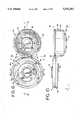
- FIG. 1is a perspective view of a container with a first embodiment of a closure in accordance with the teachings of one aspect of the present invention
- FIG. 2is an enlarged, perspective of the closure illustrated in FIG. 1, but the closure is shown inverted relative to the position in FIG. 1;
- FIG. 3is a view similar to FIG. 2, but with portions cut away to illustrate interior detail;
- FIG. 4is a fragmentary view similar to FIG. 2, but FIG. 4 shows the tamper-evident seal removed;
- FIG. 5is a fragmentary, cross-sectional view of the closure in place ion the container as shown in FIG. 1, but with the container inverted from the position shown in FIG. 1;
- FIG. 6is a perspective view of the slit valve removed from the closure illustrated in FIG. 5;
- FIG. 7is a top plan view of the valve shown in FIG. 6;
- FIG. 8is a side elevational view of the valve shown in FIG. 6;
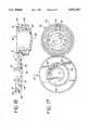
- FIG. 9is a view, similar to FIG. 5, but the closure is shown in FIG. 9 inverted relative to the orientation shown in FIG. 5 and is shown with the container contents filling the container neck and subjected to a transient overpressure condition;
- FIG. 10is a view similar to FIG. 9, but FIG. 10 shows the closure opened with the container pressurized, as by squeezing, to dispense liquid product through the open closure;
- FIG. 11is an exploded, perspective view of the cartridge components employed in the first embodiment of the closure illustrated in FIG. 1 and other figures;
- FIG. 12is a perspective view of the cartridge of FIG. 11 in a latched closed condition prior to assembly in the housing of the first embodiment of the closure illustrated in FIG. 1 and other figures;
- FIG. 13is a side, elevational view of the open, unassembled cartridge taken generally along the plane 13--13 in FIG. 11;
- FIG. 14is a partial cross-sectional view taken generally along the plane 14--14 in FIG. 11;
- FIG. 15is a view taken generally along the plane 15--15 in FIG. 11;
- FIG. 16is a view taken generally along the plane 16--16 in FIG. 15;
- FIG. 17is a view taken generally along the plane 17--17 in FIG. 15;
- FIG. 18is a cross-sectional view taken generally along the plane 18--18 in FIG. 16;
- FIG. 19is a greatly enlarged, fragmentary, cross-sectional view taken at the encircled area designated by reference number 19 in FIG. 18;
- FIG. 20is a fragmentary, enlarged, cross-sectional view taken generally along the plane 20--20 in FIG. 16;
- FIG. 21is a fragmentary, enlarged, cross-sectional view taken generally along the plane 21--21 in FIG. 16;
- FIG. 22is a cross-sectional view taken generally along the plane 22--22 in FIG. 16;
- FIG. 23is a view similar to FIG. 22, but FIG. 23 illustrates a second embodiment of a closure having an alternate embodiment of the cartridge retainer tear-away seal;
- FIG. 24is a fragmentary, cross-sectional view of a third embodiment of a closure of the present invention.
- FIG. 25is a fragmentary, side elevational view taken generally along the plane 25--25 in FIG. 24;
- FIG. 26is a perspective view of a fourth embodiment of a closure of the present invention.
- FIG. 27is a view similar to FIG. 26, but FIG. 27 shows a portion of the closure cut away to illustrate interior detail;
- FIG. 28is a fragmentary, cross-sectional view of the closure shown in FIGS. 26 and 27 installed on a container;
- FIG. 29is a perspective view of a fifth embodiment of a closure of the present invention.
- FIG. 30is a cross-sectional view of the fifth embodiment of the closure illustrated in FIG. 29.
- FIG. 31is an alternate embodiment of a cartridge for use for the closure of the present invention, and FIG. 31 illustrates further modifications in phantom by dashed lines.
- closure system of this inventionis described in various positions, and terms such as upper, lower, horizontal, etc., are used with reference to these positions. It will be understood, however, that the closure components may be manufactured and stored in orientations other than the ones described.
- FIGS. 1-22a first embodiment of a closure that includes components of the present invention is illustrated in FIGS. 1-22 and is represented generally in many of those figures by reference numeral 40.
- the closure 40is adapted to be disposed on a container, such as a container 42 (FIGS. 1 and 5) which has a conventional mouth or opening formed by a neck 44 (FIG. 5) or other suitable structure.
- the closure 40may be fabricated from a thermoplastic material, or other materials, compatible with the container contents.
- the container 42is normally stored and used in the orientation shown in FIG. 1 wherein the closure 40 is at the bottom of the container 42. When stored, the container employs the closure 40 as a support base.
- the container 42is a squeezable container having a flexible wall or walls which can be grasped by the user and compressed to increase the internal pressure within the container so as to squeeze the product out of the container when the closure is opened (as explained in detail hereinafter).
- the container walltypically has sufficient, inherent resiliency so that when the squeezing forces are removed, the container wall returns to its normal, unstressed orientation.
- the closure 40includes a hollow housing 50 (FIGS. 1-5).
- the housing 50includes a peripheral wall in the form of a generally cylindrical skirt or collar 51 (FIGS. 3 and 5).
- the interior surface of the collar 51has a conventional thread 55 or other suitable means (e.g., a snap-fit bead (not illustrated)) for engaging suitable cooperating means, such as a thread 56 that is typically provided on the container neck 44 to releasably secure the housing 50 to the container.
- the housing 50includes a recessed annular flange 57 for receiving an insert or cartridge 64 which controls flow out of the container 42.
- the central deck 57(FIG. 5) defines a dispensing opening or passage 62 (FIGS. 3, 5, 9, and 10).
- the dispensing passage 62establishes communication between the container interior and exterior through the container opening defined by the container neck 44.
- the housing 50defines an interior receiving area or structure for a novel, standardized cartridge 64 (FIGS. 3, 5, And 12).
- the cartridge 64is adapted to be engaged with the housing 50 and retained therein.
- the cartridge 64as illustrated in FIG. 12, has an assembled, closed configuration which is adapted to be received in the housing 50.
- the cartridgeis initially fabricated in an "open" condition and includes a body 66 and a cover or retainer 68.
- the body 66 and retainer 68are molded from a suitable thermoplastic material as a unitary structure with a hinge 69 extending between, and connecting, the body 66 and retainer 68.
- the body 66, retainer 68, and hinge 69may be molded from polyethylene or polypropylene as a unitary structure in the open configuration substantially as illustrated in FIGS. 11, 13, 14, 15, 16, 17, and 18.
- the cartridge 64also includes a flexible, resilient, slit-type dispensing valve 70 (FIG. 11) which is mounted in the housing 66 and retained therein by the retainer 68 when the cartridge is in the closed configuration (FIG. 12).
- a flexible, resilient, slit-type dispensing valve 70(FIG. 11) which is mounted in the housing 66 and retained therein by the retainer 68 when the cartridge is in the closed configuration (FIG. 12).
- the valve 70is mounted at the passage 62 inwardly of the central deck 57 as illustrated in FIG. 3.
- the valve 70may be fabricated from thermosetting elastomeric materials such as silicone, natural rubber, and the like. It is also contemplated that the valve 70 may be fabricated from thermoplastic elastomers based upon materials such as thermoplastic propylene, ethylene, urethane, and styrene, including their halogenated counterparts.
- the valve 70includes a flexible, central wall 72 which has an outwardly concave configuration and which defines at least one, and preferably two, dispensing slits 76 extending through the central wall 72.
- a preferred form of the valvehas two, mutually perpendicular, intersecting slits 76 of equal length.
- the intersecting slits 76define four, generally pie-shaped, flaps or petals in the concave, central wall 72 which each open outwardly from the intersection point in response to increasing pressure of sufficient magnitude in the well-known conventional manner.
- the valve 70includes a skirt 78 which extends outwardly from the valve central wall 72. At the outer (upper) end of the skirt 78 there is a thin, annular flange 80 (FIGS. 6 and 7) which extends peripherally from the skirt 78 in a downwardly angled orientation.
- the thin flange 80terminates in an enlarged, much thicker, peripheral flange 82 which has a generally dovetail shape transverse cross section.
- valve 70is disposed in the cartridge body 66 and is clamped therein by the retainer 68 which is closed over the top of the valve 70 to form the fully assembled cartridge as shown in FIGS. 5 and 12.
- the underside of the cartridge cover or retainer 68defines an annular, downwardly facing, angled clamping surface 88 (FIGS. 5 and 11) for engaging the top of the valve flange 82.
- valve flange 82The bottom of the valve flange 82 is engaged by an annular shoulder in the body 66 which defines an upwardly angled seating surface 90.
- the spacing between the clamping and seating surfaces 88 and 90, respectively,increases with increasing radial distance from the center.
- Such a configurationdefines a cavity with a transverse cross section having a dovetail shape which generally conforms to the shape of the valve flange 82.
- This clamping arrangementsecurely holds the valve 70 in the cartridge body 40 without requiring special internal support structures or bearing members adjacent the interior surface of the valve cylindrical skirt 78. This permits the region adjacent the interior surface of the valve skirt 78 to be substantially open, free, and clear so as to accommodate movement of the valve skirt 78.
- valve 70When the valve 70 is properly mounted within the body 66 as illustrated in FIGS. 3 and 4, the valve 70 is recessed relative to an outer, top, peripheral surface of the cartridge 64. This affords substantial protection to the valve and generally reduces the likelihood that the valve will be inadvertently contacted or damaged by external instrumentalities when the closure is opened but not dispensing product. However, as explained in detail hereinafter, when the product is dispensed through the valve 70, the valve is displaced outwardly from the recessed position. The capability of the valve to be displaced outwardly offers certain advantages discussed below.
- the cartridge body 66 and retainer 68have exterior configurations permitting the retainer and body to be held together in the closed configuration (FIG. 12).
- the body 66has an annular bead defining a convex surface 94 (FIG. 18) extending radially outwardly around the periphery of the upper edge of the body.
- the retainer 68defines an annular groove 96 (FIGS. 5, 9, and 18) for receiving the body bead 94 in a snap-fit engagement when the retainer 68 is closed over the installed valve 70.
- the cartridge 64is adapted to be engaged with the closure housing 50.
- the retainer 68has an outwardly projecting, annular bead 98, and the housing 50 defines an inwardly open, annular groove 100 (FIGS. 5 and 9) for receiving the cartridge retainer bead 98 when the closed cartridge is disposed within the housing in a snap-fit engagement adjacent the central deck flange 57.
- the cartridge 64preferably includes a tear-away, tamper-evident seal which includes a pull tab 102 (FIGS. 2, 3, 12, 16, 17, 18, and 22) with an end grip 108.
- the pull tab 102is defined around a central panel 104 (FIGS. 2, 3, 16, and 17).
- the central panel 104has a generally circular, disc-like configuration and is joined to the peripheral portion of the retainer 68 with a frangible web of material designated in FIGS. 16 and 17 by the reference number 106.
- An inner portion of the pull tab 102for about a 180° arc length inwardly of the pull tab 102, is connected via a frangible web 110 to the retainer central portion 104.
- the frangible webextends approximately 270° around the outside edge of the pull tab 102.
- the grip portion 108is thus not attached at its periphery to the adjacent, but spaced-away, portions of the retainer. This allows the grip portion 108 to be grasped and pulled upwardly.
- the frangible webs 106 and 110are preferably defined by a reduced-thickness portion of the material. As illustrated in FIG. 22, the top surface and the bottom surface of the retainer 68 may be provided with grooves or notches for defining the reduced-thickness frangible web regions 106 and 110.
- the grip portion 108In order to open the seal, the grip portion 108 is grasped between the thumb and index finger, and the grip portion 108 is then pulled outwardly.
- the central portion 104pulls away from the center of the retainer 68 as the frangible webs 110 and 106 are torn. When the central portion 104 is completely torn away, the valve 70 is exposed as illustrated in FIG. 4.
- an annular restraint wall 112(FIGS. 5, 9 and 18) is provided on the inside of the retainer central portion 104 adjacent the valve central wall 72. This prevents the valve central wall 72 from moving or articulating sufficiently outwardly to open the dispensing slits 76.
- the cartridge 64also includes an inwardly extending wall 120 (FIGS. 3, 5, 9, 16, 17, and 18). Projecting radially inwardly from the distal end of the wall 120 are four arms 122 (FIGS. 16 and 17) which support a centrally disposed baffle plate 124.
- the cartridge 64also includes an outer seal wall 130 (FIGS. 3, 5, 9, 10, 11, 13, 14, 15, 16, 17, and 18). As illustrated in FIG. 5, the exterior surface of the seal wall 130 is received within the container neck 44 and seals against the cylindrical interior surface of the neck 44. Preferably, at least a distal annular portion of the seal wall 130 is somewhat resilient so as to provide a leak-tight seal between the cartridge and the container neck.
- the product within the container 42can be dispensed from the container by squeezing the container sufficiently to force the product through the valve 70. Typically, this is effected by first inverting or tilting the container 42 so that the valve 70 is oriented to discharge generally downwardly. Typically, the liquid within the container flows downwardly, under the influence of gravity, and fills the container neck region. The liquid flows past the baffle 124 and against the inside of the valve central wall 72.
- the valve 70is preferably designed so that the weight of the liquid will not deflect the valve downwardly under normal, static conditions. The valve will thus be spaced away from the annular restraint wall 112 as shown in FIG. 5 (except that the container would be inverted).
- the increased pressure(which could also include the weight of the liquid within the container if the container was inverted) could deflect the valve central wall 72 downwardly against the distal end of the outwardly projecting annular restraint member 112. This might occur, for example, if the external pressure were suddenly reduced (e.g., during transport in an airplane, or if the container were subjected to an external impact force).
- the annular restraint wall 112prevents the valve 70 from moving sufficiently outwardly to open the dispensing slits 76 under such conditions.
- valve central wall 72is displaced outwardly while still maintaining its generally concave configuration.
- the outward displacement of the concave, central wall 72is accommodated by the relatively thin, flexible, skirt 78.
- the skirt 78moves from a rest position (FIG. 5) to the pressurized position (FIG. 10) wherein the skirt is projecting outwardly through, and beyond, the dispensing opening.
- the valve 70does not open (i.e., the slits 76 do not open) until the valve central wall 72 has moved substantially all the way to the outermost position. Indeed, as the valve central wall 72 moves outwardly, the central wall 72 is subjected to radially inwardly directed compression forces which tend to further resist opening of the slits 76. Further, the central wall 72 generally retains its outwardly concave configuration as it moves forward and even after it reaches the outermost position (FIG. 10). If the internal pressure is sufficiently great, then the slits 76 begin to open to dispense product as diagrammatically illustrated in FIG. 10.
- valve central wall 72is located at its outermost position when dispensing product, the dispensing process can be more easily observed by the user. Further, because the valve dispenses product when it is in the outermost position and not in the recessed position (FIG. 5), the valve can be more easily directed to dispense the product at a selected target site.
- baffle plate 124functions to minimize undesirable impacts on the inside of the valve 70, as when the container is being squeezed excessively hard or shaken.
- the baffle plate 124also functions in this manner even when the closure is sealed closed with the annular restraint member 112 in place.
- the restraint member 112when the annular restraint member 112 is in place, and when pressure transients force the valve 70 against the restraint member 112, the restraint member also functions, in addition to preventing excessive movement of the valve 70 toward the open position, as a seal on the outer surface of the valve central wall 72.
- the sealing engagement illustrated in FIG. 9will at least initially contain the leaking product on the inside of the annular restraint member 112.
- a variety of different sizes and shapes of containerscan be readily provided with a closure 40 having a standardized cartridge 64.
- the cartridge, including the valve 70,can be provided in one, universal design having a standard shape and standard dimensions.
- the inside of the closure housing 50can be provided with a receiving region of a standard shape and size for the standard cartridge 64. Thus, only the housing skirt 51 need be changed as necessary to accommodate a container neck having a particular size and shape.
- a standard cartridge with a standard valvepermits the use of a single manufacturing process to assemble the valve in the cartridge.
- the cartridgecan thereafter be readily handled at a high rate of speed by automatic machinery which installs the cartridge in the closure housing. This eliminates the need for directly handling a small, flexible valve during installation in a larger closure housing.
- a unitary cartridgewhich includes the unitary body, hinge, and retainer, minimizes the number of separate parts that must be handled. Further, the snap-engagement of the cartridge retainer with the cartridge body over the body flange permits a relatively rapid and efficient assembly process for capturing the valve. Subsequently, the snap-fit engagement of the cartridge in the closure housing accommodates relatively high speed production with a minimum product reject rate.
- the cartridgecan be fabricated in one color, and the closure housing can be molded in another color.
- the tear-away tab 102 and central portion 104may be completely eliminated. In such a case, the closure would have the appearance as shown in FIG. 4, and the valve 70 would be exposed at all times.
- FIG. 23illustrates the use of a flexible, disk-like seal 140 which is adhesively attached to the flat, exterior, end surface of the retainer 68.
- FIGS. 24 and 25Another form of a closure incorporating the principles of the present invention is illustrated in FIGS. 24 and 25.
- a closure 142has a generally rectangular configuration and is disposed on the top of a container 144.
- the container 144has a neck 146.
- the neck 146is covered on two opposing sides and at the rear by a shroud 148.
- the closure 142includes a deck 150 with a downwardly depending front wall 152.
- the deck 150defines an opening 154, and a collar 156 depends downwardly from the underside of the deck 150 around the container neck 146.
- the distal end of the closure collar 156includes an inwardly projecting bead 158 for engaging an outwardly projecting bead 160 on the container neck 146.
- a cartridge 164is mounted within the closure collar 156 at the top of the container neck 146.
- the closure 164includes a body 166 and a retainer 168 engaged around a valve 170.
- the cartridge body 166, retainer 168, and valve 170may be substantially identical to the body 66, retainer 68, and valve 70 described above with reference to the first embodiment of the cartridge 64 illustrated in FIGS. 1-22.
- the cartridge 164is retained via a friction-fit or snap-fit engagement with the inside surface of the closure housing collar 156.
- the closure housing deck 150extends directly over the peripheral portion of the retainer 168.
- the cartridge 164does not include the pull tab 102 and central portion 104 employed in the cartridge 64 described above with reference to the cartridge 64 illustrated in FIGS. 1-22.
- the closurehas a hinged lid 171 with a downwardly projecting, annular, restraint member 173. When the lid 171 is closed (in the position illustrated in FIG. 24), the annular restraint member 173 is positioned relative to the valve 170 in a manner similar to the positioning of the first embodiment restraint member 112 relative to the valve 70 as described above with reference to FIGS. 1-22.
- FIGS. 26-28illustrate another embodiment of a closure 240 incorporating the principles of the present invention.
- a closureis adapted to be mounted on the neck 2.44 of a container 242.
- the container neck 244has threads 256
- the closure 240has threads 255 for engaging the container neck threads.
- the closure neck threads 255are defined in a housing 250 which receives a cartridge 264.
- the cartridge 64is identical to the cartridge 64 described above with reference to the first embodiment of the closure illustrated in FIGS. 1-22.
- the relationship of the cartridge 64 with the housing 250is somewhat different in the closure 240 compared with the relationship of the cartridge 64 with the housing 50 in the closure 40 illustrated in FIGS. 1-22.
- the closure 240has a maximum diameter which is greater than the cartridge 64 for engaging a larger diameter neck 244 of the container 242.
- the inside cylindrical surface of the container neck 244is not engaged by the cartridge collar 130.
- the housing 250has a downwardly projecting, flexible seal member 259 which engages the top, annular surface of the container neck 244 to provide a seal.
- FIG. 28a standardized cartridge 64 may be employed in housings having different diameters (and different container engagement configurations).
- FIGS. 29 and 30another embodiment of a closure, with still a different container engagement configuration, is illustrated in FIGS. 29 and 30 wherein the closure is generally designated by the reference number 340.
- the closure 340includes a housing 350 having an outer, cylindrical wall 351 and an inner, cylindrical wall 353.
- the inside surface of the cylindrical wall 353defines a thread 355 for engaging a mating thread on the neck of a container (not shown).
- the housing 350also defines a recessed deck 357 defining an opening 362 affording communication between the container and the exterior of the housing. Projecting upwardly from the deck 357 is a collar 359.
- the collar 359is a generally cylindrical wall disposed radially outwardly of the opening 362.
- the housing 350receives a cartridge 64 identical to the cartridge 64 described above with reference to the first embodiment of the closure illustrated in FIGS. 1-22.
- the cartridge 64includes the above-described, downwardly depending collar 130, and the outside surface of the collar 130 sealingly engages the inside surface of the closure collar 359 to establish a seal.
- Another sealis established between the bottom of the closure deck 357 and the top of the container neck with a flexible annular seal member 359 which extends downwardly from the deck 357 as shown in FIG. 30.
- the cartridge 64can be modified according to the principles of the present invention, and FIG. 31 illustrates such a modification wherein the modified cartridge is designated generally by the reference number 464.
- the cartridge 464includes a body 466 molded in a unitary construction with a retainer 468 which is connected to the body 466 with a flexible strap or hinge 469.
- the retainer 468has a ring-like configuration defining a central opening 471.
- a valve 470is retained in the body 466 by the retainer 469 which is snap-fit into a groove 467 in the body 466.
- the valve 470may be identical or substantially identical to the valve 70 described above with reference to the embodiment illustrated in FIGS. 1-22.
- the opening 471 in the retainer 468is not covered with a seal, such as the pull tab 102 and central portion cover 104 described above with reference to the embodiment illustrated in FIGS. 1-22.
- the cartridge 464 illustrated in FIG. 31may be used immediately to dispense the product from the container through the valve 470 without having to remove a seal structure or other closure component.
- the cartridge body 466defines a bead 473 which extends at least part way around the periphery of the body 466 for engaging a mating groove in a closure housing so as to effect the mounting of the cartridge 464 in such a closure housing.
- the bead 473is thus functionally analogous to the bead 98 on the first embodiment of the cartridge 64 which is received in the housing groove 100 as illustrated in FIG. 5.
- the cartridge bead 473is defined by the body 466, and not by the retainer. This is in contrast with the cartridge 64 illustrated in FIG. 5 wherein the bead is defined on the retainer 68.
- the cartridge 464 illustrated in FIG. 31may be modified.
- the top of the body 466may be covered with an adhesively secured, removable sealing member 481 as illustrated in dotted lines in FIG. 31.
- a removable sealing member 481would serve a function analogous to that of the removable member 140 described above with reference to the embodiment illustrated in FIG. 23.
- the member 481would provide an additional barrier between the container contents and the exterior of the closure.
- the member 481could also serve as a tamper-evident feature.
- the cartridge 464may be modified in other ways also.
- the cartridge 464may be provided with exterior threads 487 as illustrated in dotted lines in FIG. 31.
- Such threadscould be employed with a special container having an internally threaded neck for securing the cartridge directly to the container.
- the cartridge 464, as thus modified,would, in effect, become a complete closure for the container.
- the cartridge 464could be provided with an additional, outer cylindrical wall (not illustrated) that is spaced beyond, and is concentric with, the cylindrical wall of the body 466 illustrated in FIG. 31.
- the inner surface of such an additional, outer wallcould be provided with an internal thread for engaging a conventional exterior thread on the neck of a conventional container.
- Such a modified cartridgewould also become, in effect, a complete closure for the container.
- a closuremay be provided with a cartridge, such as the cartridge 64 illustrated in FIGS. 1-22, wherein the body 66 and retainer 68 are not molded together as a unitary piece.
- the hinge 69FIG. 16
- Such a hingeless cartridgemay or may not include a seal member, such as the seal member 140 illustrated in FIG. 23 or such as the pull tab 102 and central portion 104 illustrated in FIG. 2.
Landscapes
- Engineering & Computer Science (AREA)
- Mechanical Engineering (AREA)
- Closures For Containers (AREA)
- Containers And Packaging Bodies Having A Special Means To Remove Contents (AREA)
- Details Of Rigid Or Semi-Rigid Containers (AREA)
- Packages (AREA)
- Feeding And Controlling Fuel (AREA)
Abstract
Description
Claims (16)
Priority Applications (11)
| Application Number | Priority Date | Filing Date | Title |
|---|---|---|---|
| US08/258,659US5531363A (en) | 1994-06-10 | 1994-06-10 | Dispensing closure cartridge valve system |
| TW085205419UTW330566U (en) | 1994-06-10 | 1995-03-20 | Cartridge having a dispensing valve and closure containing said cartridge |
| CA002188419ACA2188419A1 (en) | 1994-06-10 | 1995-03-24 | Dispensing closure cartridge valve system |
| PCT/US1995/003732WO1995034500A1 (en) | 1994-06-10 | 1995-03-24 | Dispensing closure cartridge valve system |
| BR9507957ABR9507957A (en) | 1994-06-10 | 1995-03-24 | Administer cartridge cartridge valve system |
| JP50212696AJP3753433B2 (en) | 1994-06-10 | 1995-03-24 | Cartridge valve device for distribution lid |
| AU21285/95AAU685616B2 (en) | 1994-06-10 | 1995-03-24 | Dispensing closure cartridge valve system |
| CN95193544ACN1150412A (en) | 1994-06-10 | 1995-03-24 | Dispensing closure cartridge valve system |
| EP95914191AEP0762988A4 (en) | 1994-06-10 | 1995-03-24 | Dispensing closure cartridge valve system |
| CO95012884ACO4410225A1 (en) | 1994-06-10 | 1995-03-30 | DISPENSER CLOSING CARTRIDGE VALVE SYSTEM |
| MXPA/A/1996/005641AMXPA96005641A (en) | 1994-06-10 | 1996-11-18 | Distribuc closure cartridge valve system |
Applications Claiming Priority (1)
| Application Number | Priority Date | Filing Date | Title |
|---|---|---|---|
| US08/258,659US5531363A (en) | 1994-06-10 | 1994-06-10 | Dispensing closure cartridge valve system |
Publications (1)
| Publication Number | Publication Date |
|---|---|
| US5531363Atrue US5531363A (en) | 1996-07-02 |
Family
ID=22981563
Family Applications (1)
| Application Number | Title | Priority Date | Filing Date |
|---|---|---|---|
| US08/258,659Expired - LifetimeUS5531363A (en) | 1994-06-10 | 1994-06-10 | Dispensing closure cartridge valve system |
Country Status (10)
| Country | Link |
|---|---|
| US (1) | US5531363A (en) |
| EP (1) | EP0762988A4 (en) |
| JP (1) | JP3753433B2 (en) |
| CN (1) | CN1150412A (en) |
| AU (1) | AU685616B2 (en) |
| BR (1) | BR9507957A (en) |
| CA (1) | CA2188419A1 (en) |
| CO (1) | CO4410225A1 (en) |
| TW (1) | TW330566U (en) |
| WO (1) | WO1995034500A1 (en) |
Cited By (68)
| Publication number | Priority date | Publication date | Assignee | Title |
|---|---|---|---|---|
| WO1998002361A1 (en)* | 1996-07-11 | 1998-01-22 | Aptargroup, Inc. | One-piece dispensing system and method for making same |
| WO1998034848A1 (en) | 1997-02-06 | 1998-08-13 | Aptargroup, Inc. | Snap-action closure with disengaged compression member |
| US5839626A (en)* | 1996-04-04 | 1998-11-24 | Aptargroup, Inc. | Valve-controlled dispensing closure with dispersion baffle |
| US5853109A (en)* | 1998-04-29 | 1998-12-29 | Aptargroup, Inc. | Dispensing structure with displaceable penetrator and bistable cover actuator |
| WO1998058847A1 (en)* | 1997-06-23 | 1998-12-30 | Crown Cork & Seal Technologies Corporation | Dispensing closure with pressure actuated valve |
| USD404307S (en) | 1997-09-09 | 1999-01-19 | Johnson & Johnson Consumer Products, Inc. | Bottle |
| US5890655A (en)* | 1997-01-06 | 1999-04-06 | The Procter & Gamble Company | Fan spray nozzles having elastomeric dome-shaped tips |
| USD411745S (en) | 1997-09-09 | 1999-06-29 | Johnson & Johnson Consumer Products, Inc. | Angled cap |
| US5927549A (en)* | 1998-03-20 | 1999-07-27 | Aptargroup, Inc. | Dispensing structure with frangible membrane for separating two products |
| US5927567A (en)* | 1996-11-12 | 1999-07-27 | Owens-Illinois Closure Inc. | Dispensing closure and method of making |
| US5938087A (en)* | 1997-06-17 | 1999-08-17 | Aptargroup, Inc. | Spurt minimizing dispensing structure |
| US5971232A (en)* | 1998-06-03 | 1999-10-26 | Aptargroup, Inc. | Dispensing structure which has a pressure-openable valve retained with folding elements |
| US6003728A (en)* | 1998-10-22 | 1999-12-21 | Aptargroup, Inc. | Dispensing structure with an openable member for separating two products |
| US6006960A (en)* | 1998-10-28 | 1999-12-28 | Aptargroup, Inc. | Dispensing structure which has a lid with a pressure-openable valve |
| US6045004A (en) | 1998-03-20 | 2000-04-04 | Aptargroup, Inc. | Dispensing structure with dispensing valve and barrier penetrator |
| USD426464S (en)* | 1997-09-09 | 2000-06-13 | Johnson & Johnson Consumer Companies, Inc. | Combined bottle and cap |
| US6079594A (en)* | 1997-08-21 | 2000-06-27 | Seaquist Closures Foreign, Inc. | Dispensing package with a self-sealing closure constructed from a thermoplastic material |
| US6095381A (en)* | 1995-09-05 | 2000-08-01 | Zeller Plastik Gmbh | Self-closing seal with a sealing membrane |
| USD438801S1 (en) | 1997-09-09 | 2001-03-13 | Johnson&Johnson Consumer Products, Inc. | Combined bottle and cap |
| US6213355B1 (en) | 1996-05-30 | 2001-04-10 | Zeller Plastik Gmbh | Closure membrane and closure employing same |
| USD441292S1 (en) | 1997-09-09 | 2001-05-01 | Johnson & Johnson Consumer Products, Inc. | Bottle |
| USD448242S1 (en) | 1999-12-30 | 2001-09-25 | Johnson & Johnson Consumer Companies, Inc. | Trainer cup |
| USD448976S1 (en) | 1999-12-30 | 2001-10-09 | Johnson & Johnson Consumer Companies, Inc. | Pinched trainer cup |
| US6305571B1 (en)* | 2000-06-07 | 2001-10-23 | Donny Chu | Lid device with splashless baffle |
| USD450535S1 (en) | 1999-12-30 | 2001-11-20 | Mcdonough Justin E. | Trainer cup |
| US6367668B1 (en) | 1996-10-01 | 2002-04-09 | Crown Cork & Seal Technologies Corporation | Self-closing closure and closure membrane relating to same |
| US6371340B1 (en)* | 1998-11-17 | 2002-04-16 | Crown Cork & Seal Technologies Corporation | Dispensing closures |
| US6616016B2 (en) | 2001-12-07 | 2003-09-09 | Seaquist Closures Foreign, Inc. | Closure with pressure-actuated valve and lid seal |
| US6672487B1 (en) | 2002-06-07 | 2004-01-06 | Owens-Illinois Closure Inc. | Fluid dispensing closure, package and method of manufacture |
| US6910607B2 (en) | 2002-03-15 | 2005-06-28 | Crown Cork & Seal Technologies Corporation | Cover for dispensing closure with pressure actuated valve |
| US20050279781A1 (en)* | 2004-06-22 | 2005-12-22 | Pugne Darin M | Dispensing closure, package and method of manufacture |
| US20060048841A1 (en)* | 2002-07-26 | 2006-03-09 | Gfi Innovations, Llc | Methodology and apparatus for storing and dispensing liquid components to create custom formulations |
| US20060049208A1 (en)* | 2004-09-09 | 2006-03-09 | Daansen Warren S | Slit valves and dispensing nozzles employing same |
| US20060113331A1 (en)* | 2004-11-30 | 2006-06-01 | Kranson Industries, Inc., D/B/A Tricorbraun | Molded collapsible blow dome apparatus and method |
| US20060169723A1 (en)* | 2005-01-28 | 2006-08-03 | Owens-Illinois Closure Inc. | Dispensing closure, package and method of manufacture |
| US20080035677A1 (en)* | 2004-09-09 | 2008-02-14 | Daansen Warren S | Nozzle tip with slit valve for fluid dispenser |
| US20080110938A1 (en)* | 2006-11-13 | 2008-05-15 | Fun-Damental Too, Ltd. | Forcibly sealed duckbill valve |
| US20080173677A1 (en)* | 2007-01-19 | 2008-07-24 | Hickok Alan P | Valve carrier ring assembly |
| WO2008118304A1 (en)* | 2007-03-27 | 2008-10-02 | Liquid Molding Systems, Inc. | Dispensing valve with hydraulic hammer resistance |
| US20090256101A1 (en)* | 2008-04-09 | 2009-10-15 | Hatton Jason D | Valve Assembly |
| US20090267011A1 (en)* | 2008-04-23 | 2009-10-29 | Jason Hatton | Dispensing valve assembly |
| US20100108058A1 (en)* | 2006-10-25 | 2010-05-06 | Mark Glusker | Powder dispersion apparatus, method of making and using the apparatus, and components that can be used on the apparatus and other devices |
| US20100116371A1 (en)* | 2008-11-11 | 2010-05-13 | Liquid Molding Systems, Inc. | Port closure system with hydraulic hammer resistance |
| US20100133273A1 (en)* | 2008-10-22 | 2010-06-03 | Charles Thurman | Self sealing bag in box cap assembly |
| US20110163134A1 (en)* | 2010-01-06 | 2011-07-07 | Bloom Kenneth S | Dispensing valve |
| US20120187158A1 (en)* | 2011-01-20 | 2012-07-26 | Fres-Co System Usa, Inc. | Dispensing closure system, flexible package with a dispensing closure system, method of filling the same by a form-fill-seal machine and method of dispensing a flowable product from said package |
| US20120193362A1 (en)* | 2011-02-01 | 2012-08-02 | Granite State Product Development LLC | Dispensing cap for a container |
| ES2388101A1 (en)* | 2010-07-27 | 2012-10-08 | Trebolin Plásticos S.L. | Assembly of plug and valve for vessels and manufacturing procedure of the same. (Machine-translation by Google Translate, not legally binding) |
| US8608034B2 (en) | 2011-02-18 | 2013-12-17 | Berry Plastics Corporation | Dispensing valve |
| US8757442B2 (en) | 2012-01-10 | 2014-06-24 | Holdenart, Inc. | Reversible spout for bottles |
| US20140182715A1 (en)* | 2012-12-21 | 2014-07-03 | Manitowoc Foodservice Companies, Llc | Method and system for securing and removing a liquid molding system valve from a beverage dispenser |
| US20150108180A1 (en)* | 2013-10-21 | 2015-04-23 | The Elleven s.r.o. | Spray and splash reducing cap |
| USD728378S1 (en) | 2013-03-15 | 2015-05-05 | Tc Heartland Llc | Container |
| US20150265106A1 (en)* | 2007-05-16 | 2015-09-24 | Ultraclenz, Llc | Keyed dispensing cartridge with valve insert |
| US20150291341A1 (en)* | 2012-12-10 | 2015-10-15 | Kao Germany Gmbh | Nozzle for a two-chamber container for mixing two components and applying the mixture |
| WO2016164007A1 (en)* | 2015-04-08 | 2016-10-13 | Aptargroup, Inc. | Flow control device and process |
| US9580214B2 (en) | 2011-05-04 | 2017-02-28 | Aptargroup, Inc. | Port closure system for use with a probe/feed/drain tool |
| USD806545S1 (en)* | 2017-05-03 | 2018-01-02 | Can't Live Without It, LLC | Drink-through cap for a beverage bottle |
| US20180029863A1 (en)* | 2016-07-29 | 2018-02-01 | Berry Plastics Corporation | Liquid dispenser |
| US10065775B2 (en) | 2011-02-01 | 2018-09-04 | Granite State Product Development LLC | Dispensing cap for a container |
| US10228069B2 (en) | 2015-11-06 | 2019-03-12 | Oklahoma Safety Equipment Company, Inc. | Rupture disc device and method of assembly thereof |
| US20190161245A1 (en)* | 2017-11-27 | 2019-05-30 | Gateway Plastics, Inc. | Valve for a dispensing container |
| US20190358667A1 (en)* | 2017-10-23 | 2019-11-28 | Aptargroup, Inc. | Valve |
| US10518943B2 (en) | 2013-03-15 | 2019-12-31 | Tc Heartland Llc | Container with valve |
| US10569286B2 (en) | 2017-05-08 | 2020-02-25 | Ecolab Usa Inc. | Shaped cartridge dispensing systems |
| US20210308714A1 (en)* | 2018-08-29 | 2021-10-07 | Ingersoll Products Inc. | Collar For Use With A Casing And An Applicator |
| US11390442B2 (en)* | 2017-12-06 | 2022-07-19 | Vitop Moulding S.R.L. | Delivering tap equipped with internal silicone valve with automatic closure with multiple liquid-sealing and tamper-preventing systems |
| KR20230092240A (en)* | 2021-12-17 | 2023-06-26 | (주) 디.에이치.테크 | Dispensing cap with a flexible inner valve for container |
Families Citing this family (12)
| Publication number | Priority date | Publication date | Assignee | Title |
|---|---|---|---|---|
| US5839614A (en) | 1991-12-06 | 1998-11-24 | Aptar Group, Inc. | Dispensing package |
| US5680969A (en)* | 1995-12-18 | 1997-10-28 | Aptargroup, Inc. | Closure with dispensing valve and separate releasable internal shipping seal |
| DE29703275U1 (en)* | 1997-02-25 | 1998-06-25 | Weener Plastik GmbH & Co KG, 26826 Weener | Sealing membrane |
| EP1917205B1 (en)* | 2004-11-29 | 2011-12-28 | AptarGroup, Inc | Dispenser with lock |
| US7731066B2 (en)* | 2005-08-04 | 2010-06-08 | Colgate-Palmolive Company | Closure |
| US9010589B2 (en)* | 2008-10-22 | 2015-04-21 | Scholle Corporation | Self sealing bag in box cap assembly |
| US9505603B2 (en)* | 2012-11-29 | 2016-11-29 | Entegris, Inc. | Single use dispense head with key code |
| RU2666214C2 (en)* | 2014-06-12 | 2018-09-06 | Конинклейке Филипс Н.В. | Closure for beverage container |
| CN106424715B (en)* | 2016-09-07 | 2019-03-12 | 重庆市九瑞粉末冶金有限责任公司 | A kind of powder metallurgy container containing |
| CN106275785A (en)* | 2016-09-07 | 2017-01-04 | 重庆市九瑞粉末冶金有限责任公司 | A kind of metallurgical powder packaging bag |
| US10591932B2 (en) | 2017-11-08 | 2020-03-17 | Carefusion Corporation | Diaphragm check valve |
| KR102809109B1 (en)* | 2023-07-07 | 2025-05-20 | (주)선앤엘 | Container cap |
Citations (69)
| Publication number | Priority date | Publication date | Assignee | Title |
|---|---|---|---|---|
| US1607993A (en)* | 1925-12-11 | 1926-11-23 | Raymond G F Loewy | Container tube |
| US1658233A (en)* | 1925-08-21 | 1928-02-07 | Bay State Collapsible Tube Com | Discharge nipple for collapsible tubes |
| US1739871A (en)* | 1926-11-15 | 1929-12-17 | Arthur E Smith | Receptacle closure |
| FR673584A (en)* | 1928-08-24 | 1930-01-16 | Improvements to self-closing shutters for crush tubes and other similar containers | |
| US1748682A (en)* | 1928-05-28 | 1930-02-25 | Arthur E Smith | Automatic valve for closures |
| GB344215A (en)* | 1930-02-27 | 1931-03-05 | Charles Fowler | Improvements in closures for collapsible tubes and other containers |
| US1825553A (en)* | 1926-11-15 | 1931-09-29 | Arthur E Smith | Container closure |
| US1989145A (en)* | 1933-10-06 | 1935-01-29 | Neal D Newby | Cap for collapsible tubes |
| US1989714A (en)* | 1930-09-23 | 1935-02-05 | Statham Noel | Self-sealing valve |
| US1996156A (en)* | 1932-02-23 | 1935-04-02 | Janssen Oscar | Dispensing apparatus |
| US2061124A (en)* | 1936-01-29 | 1936-11-17 | George J Walther | Collapsible tube closure |
| US2591354A (en)* | 1947-06-10 | 1952-04-01 | Griffiths Hughes Ltd E | Means for holding and extruding paste and liquid materials |
| US2679954A (en)* | 1951-05-23 | 1954-06-01 | James F Barnes | Dispensing container having a slitted resilient closure disk and a sealing tab |
| US2688979A (en)* | 1951-08-31 | 1954-09-14 | John F Kendrick | Abrasion resistant check valve |
| US2705085A (en)* | 1952-09-23 | 1955-03-29 | West Co | Bottle cap structure |
| US2720881A (en)* | 1953-06-08 | 1955-10-18 | Jones John Leslie | Closure |
| US2743852A (en)* | 1956-05-01 | Closure cap for collapsible containers | ||
| US2758755A (en)* | 1953-04-15 | 1956-08-14 | Schafler Kay | Compressible container with automatically closing and retracting discharge nozzle |
| US2787394A (en)* | 1954-01-21 | 1957-04-02 | Baxter Laboratories Inc | Closure |
| US2802607A (en)* | 1953-05-11 | 1957-08-13 | Jr Phillip Kalmbach | Dispensing cap for collapsible tubes |
| US2937795A (en)* | 1957-04-24 | 1960-05-24 | Ciliberti Pasquale | Dispenser closure cap-seal itself |
| US2941544A (en)* | 1955-09-27 | 1960-06-21 | Renault | Fluid control devices and elastic pressure-responsive valves |
| US2942762A (en)* | 1957-04-08 | 1960-06-28 | Fahr Morris | Dispenser for toilet lotions |
| US3067787A (en)* | 1959-05-12 | 1962-12-11 | Norton Salk | Dispensing container |
| US3165241A (en)* | 1963-01-25 | 1965-01-12 | Irene V M Curry | Feeder for invalids |
| US3179301A (en)* | 1964-02-17 | 1965-04-20 | Battelle Development Corp | Squeeze-type dispensing head |
| US3257046A (en)* | 1964-09-28 | 1966-06-21 | James Paul O Sullivan | Dispensing cap for collapsible tubes |
| US3258028A (en)* | 1963-08-27 | 1966-06-28 | Verne P Donner | Pressure relief valve |
| US3270771A (en)* | 1963-06-11 | 1966-09-06 | Robertshaw Controls Co | Resilient disc check valve |
| US3281000A (en)* | 1964-08-17 | 1966-10-25 | Lowen Stanley | Closure apparatus |
| AT251478B (en)* | 1963-06-18 | 1967-01-10 | Roma Ind Pty Ltd | Dispensing device |
| US3366261A (en)* | 1965-05-13 | 1968-01-30 | Carole R. Dewey | Dispenser valve |
| US3669323A (en)* | 1969-12-12 | 1972-06-13 | American Can Co | One-way valve insert for collapsible dispensing containers |
| US3674183A (en)* | 1971-02-01 | 1972-07-04 | Herny B Venable | Dispensing device |
| US3726436A (en)* | 1971-04-14 | 1973-04-10 | Despain Flandro | Dispenser with flap valve |
| US3795558A (en)* | 1971-11-08 | 1974-03-05 | Cutter Lab | Method of ultrasonic sealing hollow members |
| DE2354093A1 (en)* | 1973-10-29 | 1975-05-07 | Dohle | Compressible closed container for perishable goods - has valve preventing air entry and dispensing only under external pressure |
| GB1474620A (en)* | 1974-09-18 | 1977-05-25 | Blendax Werke Schneider Co | Tube closure |
| US4036412A (en)* | 1974-03-11 | 1977-07-19 | Loren S. Fond | Elastomeric cartridge with slitted nozzle tip |
| US4109836A (en)* | 1977-02-10 | 1978-08-29 | Anna Falarde | Self-sealing paste dispensing device |
| US4133457A (en)* | 1976-03-08 | 1979-01-09 | Klassen Edward J | Squeeze bottle with valve septum |
| US4269330A (en)* | 1979-10-11 | 1981-05-26 | Johnson Terry J | Cartridge type sauce extruder |
| US4513891A (en)* | 1982-04-15 | 1985-04-30 | Sterling Drug Inc. | Spray dispensing container and valve therefor |
| US4616768A (en)* | 1983-06-07 | 1986-10-14 | Lingner & Fischer Gmbh | Discharge barrier for collapsible tubes |
| US4620648A (en)* | 1982-07-06 | 1986-11-04 | Dab-O-Matic Corp. | Pressure-responsive valve |
| US4646945A (en)* | 1985-06-28 | 1987-03-03 | Steiner Company, Inc. | Vented discharge assembly for liquid soap dispenser |
| US4682702A (en)* | 1986-06-27 | 1987-07-28 | Sunbeam Plastics Corporation | Tamper indicating closure |
| EP0253495A2 (en)* | 1986-07-14 | 1988-01-20 | Blairex Laboratories Inc. | Storage bottle for contact lens cleaning solution |
| US4728006A (en)* | 1984-04-27 | 1988-03-01 | The Procter & Gamble Company | Flexible container including self-sealing dispensing valve to provide automatic shut-off and leak resistant inverted storage |
| US4735334A (en)* | 1986-08-07 | 1988-04-05 | Sunbeam Plastics Corporation | Dispensing closure |
| US4749108A (en)* | 1986-12-19 | 1988-06-07 | The Procter & Gamble Company | Bimodal storage and dispensing package including self-sealing dispensing valve to provide automatic shut-off and leak-resistant inverted storage |
| US4760937A (en)* | 1986-06-16 | 1988-08-02 | Evezich Paul D | Squeezable device for ejecting retained materials |
| US4776495A (en)* | 1986-04-16 | 1988-10-11 | Alpha Systemes | Disposable dispenser pump for products in liquid or paste form |
| DE8814121U1 (en)* | 1988-11-11 | 1988-12-29 | Braunschweiger Metallverpackungsgesellschaft mbH, 3300 Braunschweig | Plastic closure |
| US4874369A (en)* | 1987-07-27 | 1989-10-17 | Baxter International Inc. | Self-priming injection site with check valve |
| US4922955A (en)* | 1988-12-16 | 1990-05-08 | Plasson Maagan Michael Industries Ltd. | Fluid flow control device |
| US4952114A (en)* | 1988-03-11 | 1990-08-28 | Langer Ruth Geb Layher | Device for transporting adjusting frames for scaffolding |
| US4969581A (en)* | 1989-08-08 | 1990-11-13 | The Procter & Gamble Company | Unequivocal bottom delivery container with self-sealing valve |
| US4991745A (en)* | 1989-04-25 | 1991-02-12 | Liquid Molding Systems, Inc. | Dispensing valve with trampoline-like construction |
| US5005737A (en)* | 1989-06-29 | 1991-04-09 | Seaquist Closures | Flexible dispensing closure having a slitted resilient outlet valve and a flanged vent valve |
| US5033647A (en)* | 1990-03-09 | 1991-07-23 | Allergan, Inc. | Value controlled squeezable fluid dispenser |
| US5033655A (en)* | 1989-02-15 | 1991-07-23 | Liquid Molding Systems Inc. | Dispensing package for fluid products and the like |
| US5115950A (en)* | 1991-01-14 | 1992-05-26 | Seaquist Closures A Divison Of Pittway Corporation | Dispensing closure with unitary structure for retaining a pressure-actuated flexible valve |
| US5123561A (en)* | 1991-03-20 | 1992-06-23 | Gross Richard A | Closure with tamper-evident tear-off panel |
| US5213236A (en)* | 1991-12-06 | 1993-05-25 | Liquid Molding Systems, Inc. | Dispensing valve for packaging |
| US5234138A (en)* | 1990-08-29 | 1993-08-10 | L'oreal | Self-closing dispenser for a container containing a liquid or pasty product |
| US5271531A (en)* | 1991-01-14 | 1993-12-21 | Seaquist Closures, A Division Of Pittway Corp. | Dispensing closure with pressure-actuated flexible valve |
| WO1994005552A1 (en)* | 1992-09-10 | 1994-03-17 | The Procter & Gamble Company | Upright liquid containing system with self seal valve |
| US5307955A (en)* | 1992-06-25 | 1994-05-03 | The Procter & Gamble Company | Flaccid bottom delivery package having a self-sealing closure for dispensing liquid materials |
Family Cites Families (9)
| Publication number | Priority date | Publication date | Assignee | Title |
|---|---|---|---|---|
| US2125572A (en)* | 1936-07-02 | 1938-08-02 | Scovill Manufacturing Co | Dispenser |
| US3581940A (en)* | 1968-11-12 | 1971-06-01 | Alberto Culver Co | Multiple compartment dispenser container with check valves |
| US3587937A (en)* | 1969-07-18 | 1971-06-28 | Robert L Childs | Combined container and dispensing cap |
| CH675408A5 (en)* | 1987-01-17 | 1990-09-28 | Guillaume J Dorel | Plastic bottle closure for one hand operation - has 2 parts injection moulded as one closure part having dosage dome etc. and casing part having inner threaded sleeve |
| US4925055A (en)* | 1988-03-04 | 1990-05-15 | Edward S. Robbins, III | Container with unitary bladder and associated dispenser cap |
| EP0412390A1 (en)* | 1989-08-08 | 1991-02-13 | The Procter & Gamble Company | Bottom delivery package |
| WO1993009058A1 (en)* | 1991-10-29 | 1993-05-13 | The West Company, Incorporated | Improved tamper evident closure |
| AU6971694A (en)* | 1993-05-26 | 1994-12-20 | Zeller Plastik Gmbh | Closure |
| FR2711620B1 (en)* | 1993-10-21 | 1995-12-22 | Oreal | Distribution assembly equipped with a unidirectional closing member. |
- 1994
- 1994-06-10USUS08/258,659patent/US5531363A/ennot_activeExpired - Lifetime
- 1995
- 1995-03-20TWTW085205419Upatent/TW330566U/enunknown
- 1995-03-24CACA002188419Apatent/CA2188419A1/ennot_activeAbandoned
- 1995-03-24WOPCT/US1995/003732patent/WO1995034500A1/ennot_activeApplication Discontinuation
- 1995-03-24BRBR9507957Apatent/BR9507957A/ennot_activeApplication Discontinuation
- 1995-03-24CNCN95193544Apatent/CN1150412A/enactivePending
- 1995-03-24EPEP95914191Apatent/EP0762988A4/ennot_activeWithdrawn
- 1995-03-24AUAU21285/95Apatent/AU685616B2/ennot_activeCeased
- 1995-03-24JPJP50212696Apatent/JP3753433B2/ennot_activeExpired - Fee Related
- 1995-03-30COCO95012884Apatent/CO4410225A1/enunknown
Patent Citations (70)
| Publication number | Priority date | Publication date | Assignee | Title |
|---|---|---|---|---|
| US2743852A (en)* | 1956-05-01 | Closure cap for collapsible containers | ||
| US1658233A (en)* | 1925-08-21 | 1928-02-07 | Bay State Collapsible Tube Com | Discharge nipple for collapsible tubes |
| US1607993A (en)* | 1925-12-11 | 1926-11-23 | Raymond G F Loewy | Container tube |
| US1739871A (en)* | 1926-11-15 | 1929-12-17 | Arthur E Smith | Receptacle closure |
| US1825553A (en)* | 1926-11-15 | 1931-09-29 | Arthur E Smith | Container closure |
| US1748682A (en)* | 1928-05-28 | 1930-02-25 | Arthur E Smith | Automatic valve for closures |
| FR673584A (en)* | 1928-08-24 | 1930-01-16 | Improvements to self-closing shutters for crush tubes and other similar containers | |
| GB344215A (en)* | 1930-02-27 | 1931-03-05 | Charles Fowler | Improvements in closures for collapsible tubes and other containers |
| US1989714A (en)* | 1930-09-23 | 1935-02-05 | Statham Noel | Self-sealing valve |
| US1996156A (en)* | 1932-02-23 | 1935-04-02 | Janssen Oscar | Dispensing apparatus |
| US1989145A (en)* | 1933-10-06 | 1935-01-29 | Neal D Newby | Cap for collapsible tubes |
| US2061124A (en)* | 1936-01-29 | 1936-11-17 | George J Walther | Collapsible tube closure |
| US2591354A (en)* | 1947-06-10 | 1952-04-01 | Griffiths Hughes Ltd E | Means for holding and extruding paste and liquid materials |
| US2679954A (en)* | 1951-05-23 | 1954-06-01 | James F Barnes | Dispensing container having a slitted resilient closure disk and a sealing tab |
| US2688979A (en)* | 1951-08-31 | 1954-09-14 | John F Kendrick | Abrasion resistant check valve |
| US2705085A (en)* | 1952-09-23 | 1955-03-29 | West Co | Bottle cap structure |
| US2758755A (en)* | 1953-04-15 | 1956-08-14 | Schafler Kay | Compressible container with automatically closing and retracting discharge nozzle |
| US2802607A (en)* | 1953-05-11 | 1957-08-13 | Jr Phillip Kalmbach | Dispensing cap for collapsible tubes |
| US2720881A (en)* | 1953-06-08 | 1955-10-18 | Jones John Leslie | Closure |
| US2787394A (en)* | 1954-01-21 | 1957-04-02 | Baxter Laboratories Inc | Closure |
| US2941544A (en)* | 1955-09-27 | 1960-06-21 | Renault | Fluid control devices and elastic pressure-responsive valves |
| US2942762A (en)* | 1957-04-08 | 1960-06-28 | Fahr Morris | Dispenser for toilet lotions |
| US2937795A (en)* | 1957-04-24 | 1960-05-24 | Ciliberti Pasquale | Dispenser closure cap-seal itself |
| US3067787A (en)* | 1959-05-12 | 1962-12-11 | Norton Salk | Dispensing container |
| US3165241A (en)* | 1963-01-25 | 1965-01-12 | Irene V M Curry | Feeder for invalids |
| US3270771A (en)* | 1963-06-11 | 1966-09-06 | Robertshaw Controls Co | Resilient disc check valve |
| AT251478B (en)* | 1963-06-18 | 1967-01-10 | Roma Ind Pty Ltd | Dispensing device |
| US3258028A (en)* | 1963-08-27 | 1966-06-28 | Verne P Donner | Pressure relief valve |
| US3179301A (en)* | 1964-02-17 | 1965-04-20 | Battelle Development Corp | Squeeze-type dispensing head |
| US3281000A (en)* | 1964-08-17 | 1966-10-25 | Lowen Stanley | Closure apparatus |
| US3257046A (en)* | 1964-09-28 | 1966-06-21 | James Paul O Sullivan | Dispensing cap for collapsible tubes |
| US3366261A (en)* | 1965-05-13 | 1968-01-30 | Carole R. Dewey | Dispenser valve |
| US3669323A (en)* | 1969-12-12 | 1972-06-13 | American Can Co | One-way valve insert for collapsible dispensing containers |
| US3674183A (en)* | 1971-02-01 | 1972-07-04 | Herny B Venable | Dispensing device |
| US3726436A (en)* | 1971-04-14 | 1973-04-10 | Despain Flandro | Dispenser with flap valve |
| US3795558A (en)* | 1971-11-08 | 1974-03-05 | Cutter Lab | Method of ultrasonic sealing hollow members |
| DE2354093A1 (en)* | 1973-10-29 | 1975-05-07 | Dohle | Compressible closed container for perishable goods - has valve preventing air entry and dispensing only under external pressure |
| US4036412A (en)* | 1974-03-11 | 1977-07-19 | Loren S. Fond | Elastomeric cartridge with slitted nozzle tip |
| GB1474620A (en)* | 1974-09-18 | 1977-05-25 | Blendax Werke Schneider Co | Tube closure |
| US4133457A (en)* | 1976-03-08 | 1979-01-09 | Klassen Edward J | Squeeze bottle with valve septum |
| US4109836A (en)* | 1977-02-10 | 1978-08-29 | Anna Falarde | Self-sealing paste dispensing device |
| US4269330A (en)* | 1979-10-11 | 1981-05-26 | Johnson Terry J | Cartridge type sauce extruder |
| US4513891A (en)* | 1982-04-15 | 1985-04-30 | Sterling Drug Inc. | Spray dispensing container and valve therefor |
| US4620648A (en)* | 1982-07-06 | 1986-11-04 | Dab-O-Matic Corp. | Pressure-responsive valve |
| US4616768A (en)* | 1983-06-07 | 1986-10-14 | Lingner & Fischer Gmbh | Discharge barrier for collapsible tubes |
| US4728006A (en)* | 1984-04-27 | 1988-03-01 | The Procter & Gamble Company | Flexible container including self-sealing dispensing valve to provide automatic shut-off and leak resistant inverted storage |
| US4646945A (en)* | 1985-06-28 | 1987-03-03 | Steiner Company, Inc. | Vented discharge assembly for liquid soap dispenser |
| US4776495A (en)* | 1986-04-16 | 1988-10-11 | Alpha Systemes | Disposable dispenser pump for products in liquid or paste form |
| US4760937A (en)* | 1986-06-16 | 1988-08-02 | Evezich Paul D | Squeezable device for ejecting retained materials |
| US4682702A (en)* | 1986-06-27 | 1987-07-28 | Sunbeam Plastics Corporation | Tamper indicating closure |
| EP0253495A2 (en)* | 1986-07-14 | 1988-01-20 | Blairex Laboratories Inc. | Storage bottle for contact lens cleaning solution |
| US4735334A (en)* | 1986-08-07 | 1988-04-05 | Sunbeam Plastics Corporation | Dispensing closure |
| US4749108A (en)* | 1986-12-19 | 1988-06-07 | The Procter & Gamble Company | Bimodal storage and dispensing package including self-sealing dispensing valve to provide automatic shut-off and leak-resistant inverted storage |
| US4874369A (en)* | 1987-07-27 | 1989-10-17 | Baxter International Inc. | Self-priming injection site with check valve |
| US4952114A (en)* | 1988-03-11 | 1990-08-28 | Langer Ruth Geb Layher | Device for transporting adjusting frames for scaffolding |
| DE8814121U1 (en)* | 1988-11-11 | 1988-12-29 | Braunschweiger Metallverpackungsgesellschaft mbH, 3300 Braunschweig | Plastic closure |
| US4922955A (en)* | 1988-12-16 | 1990-05-08 | Plasson Maagan Michael Industries Ltd. | Fluid flow control device |
| US5033655A (en)* | 1989-02-15 | 1991-07-23 | Liquid Molding Systems Inc. | Dispensing package for fluid products and the like |
| US4991745A (en)* | 1989-04-25 | 1991-02-12 | Liquid Molding Systems, Inc. | Dispensing valve with trampoline-like construction |
| US5005737A (en)* | 1989-06-29 | 1991-04-09 | Seaquist Closures | Flexible dispensing closure having a slitted resilient outlet valve and a flanged vent valve |
| US4969581A (en)* | 1989-08-08 | 1990-11-13 | The Procter & Gamble Company | Unequivocal bottom delivery container with self-sealing valve |
| US5033647A (en)* | 1990-03-09 | 1991-07-23 | Allergan, Inc. | Value controlled squeezable fluid dispenser |
| US5234138A (en)* | 1990-08-29 | 1993-08-10 | L'oreal | Self-closing dispenser for a container containing a liquid or pasty product |
| US5115950A (en)* | 1991-01-14 | 1992-05-26 | Seaquist Closures A Divison Of Pittway Corporation | Dispensing closure with unitary structure for retaining a pressure-actuated flexible valve |
| US5271531A (en)* | 1991-01-14 | 1993-12-21 | Seaquist Closures, A Division Of Pittway Corp. | Dispensing closure with pressure-actuated flexible valve |
| US5123561A (en)* | 1991-03-20 | 1992-06-23 | Gross Richard A | Closure with tamper-evident tear-off panel |
| US5213236A (en)* | 1991-12-06 | 1993-05-25 | Liquid Molding Systems, Inc. | Dispensing valve for packaging |
| US5339995A (en)* | 1991-12-06 | 1994-08-23 | Liquid Molding Systems, Inc. | Dispensing valve for packaging |
| US5307955A (en)* | 1992-06-25 | 1994-05-03 | The Procter & Gamble Company | Flaccid bottom delivery package having a self-sealing closure for dispensing liquid materials |
| WO1994005552A1 (en)* | 1992-09-10 | 1994-03-17 | The Procter & Gamble Company | Upright liquid containing system with self seal valve |
Cited By (134)
| Publication number | Priority date | Publication date | Assignee | Title |
|---|---|---|---|---|
| US6095381A (en)* | 1995-09-05 | 2000-08-01 | Zeller Plastik Gmbh | Self-closing seal with a sealing membrane |
| US5839626A (en)* | 1996-04-04 | 1998-11-24 | Aptargroup, Inc. | Valve-controlled dispensing closure with dispersion baffle |
| US6213355B1 (en) | 1996-05-30 | 2001-04-10 | Zeller Plastik Gmbh | Closure membrane and closure employing same |
| US5927566A (en)* | 1996-07-11 | 1999-07-27 | Aptargroup, Inc. | One-piece dispensing system and method for making same |
| US6112951A (en)* | 1996-07-11 | 2000-09-05 | Aptargroup, Inc. | One-piece dispensing system and method for making same |
| WO1998002361A1 (en)* | 1996-07-11 | 1998-01-22 | Aptargroup, Inc. | One-piece dispensing system and method for making same |
| US6367668B1 (en) | 1996-10-01 | 2002-04-09 | Crown Cork & Seal Technologies Corporation | Self-closing closure and closure membrane relating to same |
| US5927567A (en)* | 1996-11-12 | 1999-07-27 | Owens-Illinois Closure Inc. | Dispensing closure and method of making |
| US7041246B2 (en) | 1996-11-12 | 2006-05-09 | Owens-Illinois Closure Inc. | Method of making a dispensing closure |
| US20040036195A1 (en)* | 1996-11-12 | 2004-02-26 | Fillmore William E. | Dispensing closure and method of making |
| US6673295B1 (en) | 1996-11-12 | 2004-01-06 | Owens-Illinois Closure Inc. | Method of making a dispensing closure |
| US5890655A (en)* | 1997-01-06 | 1999-04-06 | The Procter & Gamble Company | Fan spray nozzles having elastomeric dome-shaped tips |
| WO1998034848A1 (en) | 1997-02-06 | 1998-08-13 | Aptargroup, Inc. | Snap-action closure with disengaged compression member |
| USRE39187E1 (en)* | 1997-06-17 | 2006-07-18 | Seaquist Closures Foreign, Inc. | Spurt minimizing dispensing structure |
| US5938087A (en)* | 1997-06-17 | 1999-08-17 | Aptargroup, Inc. | Spurt minimizing dispensing structure |
| US6089418A (en)* | 1997-06-23 | 2000-07-18 | Crown Cork & Seal Technologies Corporation | Dispensing closure with pressure actuated valve |
| WO1998058847A1 (en)* | 1997-06-23 | 1998-12-30 | Crown Cork & Seal Technologies Corporation | Dispensing closure with pressure actuated valve |
| US6079594A (en)* | 1997-08-21 | 2000-06-27 | Seaquist Closures Foreign, Inc. | Dispensing package with a self-sealing closure constructed from a thermoplastic material |
| USD404307S (en) | 1997-09-09 | 1999-01-19 | Johnson & Johnson Consumer Products, Inc. | Bottle |
| USD441292S1 (en) | 1997-09-09 | 2001-05-01 | Johnson & Johnson Consumer Products, Inc. | Bottle |
| USD426464S (en)* | 1997-09-09 | 2000-06-13 | Johnson & Johnson Consumer Companies, Inc. | Combined bottle and cap |
| USD411745S (en) | 1997-09-09 | 1999-06-29 | Johnson & Johnson Consumer Products, Inc. | Angled cap |
| USD438801S1 (en) | 1997-09-09 | 2001-03-13 | Johnson&Johnson Consumer Products, Inc. | Combined bottle and cap |
| US6045004A (en) | 1998-03-20 | 2000-04-04 | Aptargroup, Inc. | Dispensing structure with dispensing valve and barrier penetrator |
| US5927549A (en)* | 1998-03-20 | 1999-07-27 | Aptargroup, Inc. | Dispensing structure with frangible membrane for separating two products |
| US5853109A (en)* | 1998-04-29 | 1998-12-29 | Aptargroup, Inc. | Dispensing structure with displaceable penetrator and bistable cover actuator |
| US5971232A (en)* | 1998-06-03 | 1999-10-26 | Aptargroup, Inc. | Dispensing structure which has a pressure-openable valve retained with folding elements |
| US6003728A (en)* | 1998-10-22 | 1999-12-21 | Aptargroup, Inc. | Dispensing structure with an openable member for separating two products |
| US6089419A (en)* | 1998-10-28 | 2000-07-18 | Aptargroup, Inc. | Dispensing structure which has a lid with a pressure-openable valve |
| US6006960A (en)* | 1998-10-28 | 1999-12-28 | Aptargroup, Inc. | Dispensing structure which has a lid with a pressure-openable valve |
| US6371340B1 (en)* | 1998-11-17 | 2002-04-16 | Crown Cork & Seal Technologies Corporation | Dispensing closures |
| USD452415S1 (en) | 1999-12-30 | 2001-12-25 | Mcdonough Justin E. | Pinched trainer cup |
| USD452116S1 (en) | 1999-12-30 | 2001-12-18 | Mcdonough Justin E. | Trainer cup |
| USD463216S1 (en) | 1999-12-30 | 2002-09-24 | Johnson & Johnson Consumer Companies, Inc. | Trainer cup |
| USD450535S1 (en) | 1999-12-30 | 2001-11-20 | Mcdonough Justin E. | Trainer cup |
| USD448976S1 (en) | 1999-12-30 | 2001-10-09 | Johnson & Johnson Consumer Companies, Inc. | Pinched trainer cup |
| USD448242S1 (en) | 1999-12-30 | 2001-09-25 | Johnson & Johnson Consumer Companies, Inc. | Trainer cup |
| US6305571B1 (en)* | 2000-06-07 | 2001-10-23 | Donny Chu | Lid device with splashless baffle |
| US6616016B2 (en) | 2001-12-07 | 2003-09-09 | Seaquist Closures Foreign, Inc. | Closure with pressure-actuated valve and lid seal |
| US6910607B2 (en) | 2002-03-15 | 2005-06-28 | Crown Cork & Seal Technologies Corporation | Cover for dispensing closure with pressure actuated valve |
| US20050269373A1 (en)* | 2002-03-15 | 2005-12-08 | Gaiser Ricky G | Cover for dispensing closure with pressure actuated valve |
| US6672487B1 (en) | 2002-06-07 | 2004-01-06 | Owens-Illinois Closure Inc. | Fluid dispensing closure, package and method of manufacture |
| US6786363B1 (en) | 2002-06-07 | 2004-09-07 | Owens-Illinois Closure Inc. | Fluid dispensing closure, package and method of manufacture |
| US20060048841A1 (en)* | 2002-07-26 | 2006-03-09 | Gfi Innovations, Llc | Methodology and apparatus for storing and dispensing liquid components to create custom formulations |
| US7255250B2 (en) | 2004-06-22 | 2007-08-14 | Owens-Illinois Closure Inc. | Dispensing closure, package and method of manufacture |
| US7861393B2 (en) | 2004-06-22 | 2011-01-04 | Rexam Closure Systems Inc. | Method of making a dispensing closure |
| US20050279781A1 (en)* | 2004-06-22 | 2005-12-22 | Pugne Darin M | Dispensing closure, package and method of manufacture |
| US20070251079A1 (en)* | 2004-06-22 | 2007-11-01 | Pugne Darin M | Dispensing closure, package and method of manufacture |
| US8899449B2 (en)* | 2004-09-09 | 2014-12-02 | Warren S. Daansen | Nozzle tip with slit valve for fluid dispenser |
| US20080035677A1 (en)* | 2004-09-09 | 2008-02-14 | Daansen Warren S | Nozzle tip with slit valve for fluid dispenser |
| US9714714B2 (en) | 2004-09-09 | 2017-07-25 | Warren S. Daansen | Nozzle tip with slit valve for fluid dispenser |
| US9254498B2 (en) | 2004-09-09 | 2016-02-09 | Warren S. Daansen | Nozzle tip with slit valve for fluid dispenser |
| US20060049208A1 (en)* | 2004-09-09 | 2006-03-09 | Daansen Warren S | Slit valves and dispensing nozzles employing same |
| US20060113331A1 (en)* | 2004-11-30 | 2006-06-01 | Kranson Industries, Inc., D/B/A Tricorbraun | Molded collapsible blow dome apparatus and method |
| US20060169723A1 (en)* | 2005-01-28 | 2006-08-03 | Owens-Illinois Closure Inc. | Dispensing closure, package and method of manufacture |
| US7398900B2 (en) | 2005-01-28 | 2008-07-15 | Owens-Illinois Closure Inc. | Dispensing closure, package and method of manufacture |
| US10245394B2 (en) | 2006-10-25 | 2019-04-02 | Mark Glusker | Powder dispersion apparatus, method of making and using the apparatus, and components that can be used on the apparatus and other devices |
| EP2668970A1 (en) | 2006-10-25 | 2013-12-04 | Novartis AG | Powder dispersion apparatus |
| US8573197B2 (en) | 2006-10-25 | 2013-11-05 | Novartis Ag | Powder dispersion apparatus, method of making and using the apparatus, and components that can be used on the apparatus and other devices |
| US20100108058A1 (en)* | 2006-10-25 | 2010-05-06 | Mark Glusker | Powder dispersion apparatus, method of making and using the apparatus, and components that can be used on the apparatus and other devices |
| US20080110938A1 (en)* | 2006-11-13 | 2008-05-15 | Fun-Damental Too, Ltd. | Forcibly sealed duckbill valve |
| US7980430B2 (en) | 2007-01-19 | 2011-07-19 | Seaquist Closures L.L.C. | Valve carrier ring assembly |
| US20080173677A1 (en)* | 2007-01-19 | 2008-07-24 | Hickok Alan P | Valve carrier ring assembly |
| EP2394925A2 (en) | 2007-01-19 | 2011-12-14 | AptarGroup, Inc | Valve carrier ring assembly |
| WO2008091490A2 (en) | 2007-01-19 | 2008-07-31 | Seaquist Closures, L.L.C. | Valve carrier ring assembly |
| CN101678914B (en)* | 2007-03-27 | 2012-05-30 | 液体成型系统公司 | Dispensing valve with hydraulic hammer resistance |
| US7784652B2 (en)* | 2007-03-27 | 2010-08-31 | Liquid Molding Systems, Inc. | Dispensing valve with hydraulic hammer resistance |
| US20080237278A1 (en)* | 2007-03-27 | 2008-10-02 | Liquid Molding Systems, Inc. | Dispensing valve with hydraulic hammer resistance |
| RU2463226C2 (en)* | 2007-03-27 | 2012-10-10 | Ликвид Молдинг Системз, Инк. | Outgiving valve with hydraulic resistance |
| WO2008118304A1 (en)* | 2007-03-27 | 2008-10-02 | Liquid Molding Systems, Inc. | Dispensing valve with hydraulic hammer resistance |
| US9730557B2 (en)* | 2007-05-16 | 2017-08-15 | Ecolab Usa Inc. | Keyed dispensing cartridge with valve insert |
| US20150265106A1 (en)* | 2007-05-16 | 2015-09-24 | Ultraclenz, Llc | Keyed dispensing cartridge with valve insert |
| US8196608B2 (en) | 2008-04-09 | 2012-06-12 | Hatton Jason D | Valve assembly |
| US8079385B2 (en) | 2008-04-09 | 2011-12-20 | Liquid Molding Systems, Inc. | Valve assembly |
| WO2009126193A1 (en)* | 2008-04-09 | 2009-10-15 | Liquid Molding Systems, Inc. | Valve assembly |
| CN102563139B (en)* | 2008-04-09 | 2014-04-09 | 液体成型系统公司 | Valve assembly |
| RU2482368C2 (en)* | 2008-04-09 | 2013-05-20 | Ликвид Молдинг Системз, Инк. | Valve unit |
| US20090256101A1 (en)* | 2008-04-09 | 2009-10-15 | Hatton Jason D | Valve Assembly |
| CN101990611B (en)* | 2008-04-09 | 2013-11-06 | 液体成型系统公司 | Valve assembly |
| US20090267011A1 (en)* | 2008-04-23 | 2009-10-29 | Jason Hatton | Dispensing valve assembly |
| WO2009131608A1 (en)* | 2008-04-23 | 2009-10-29 | Liquid Molding Systems, Inc. | Dispensing valve assembly |
| US9079694B2 (en)* | 2008-10-22 | 2015-07-14 | Scholle Corporation | Self sealing bag in box cap assembly |
| AU2009308084B2 (en)* | 2008-10-22 | 2014-05-15 | Scholle Ipn Corporation | Self-sealing bag in box cap assembly |
| US8448799B2 (en)* | 2008-10-22 | 2013-05-28 | Scholle Corporation | Self sealing bag in box cap assembly |
| US20100133273A1 (en)* | 2008-10-22 | 2010-06-03 | Charles Thurman | Self sealing bag in box cap assembly |
| US9850041B2 (en)* | 2008-10-22 | 2017-12-26 | Scholle Ipn Corporation | Self sealing bag in box cap assembly |
| US20180170624A1 (en)* | 2008-10-22 | 2018-06-21 | Scholle Ipn Corporation | Self Sealing Bag In Box Cap Assembly |
| US20130256311A1 (en)* | 2008-10-22 | 2013-10-03 | James J. Arch | Self Sealing Bag in Box Cap Assembly |
| US20100116371A1 (en)* | 2008-11-11 | 2010-05-13 | Liquid Molding Systems, Inc. | Port closure system with hydraulic hammer resistance |
| US8316890B2 (en) | 2008-11-11 | 2012-11-27 | Aptargroup, Inc. | Port closure system with hydraulic hammer resistance |
| US8397957B2 (en) | 2010-01-06 | 2013-03-19 | Berry Plastics Corporation | Dispensing valve |
| US8794489B2 (en) | 2010-01-06 | 2014-08-05 | Berry Plastics Corporation | Dispensing valve |
| US20110163134A1 (en)* | 2010-01-06 | 2011-07-07 | Bloom Kenneth S | Dispensing valve |
| ES2388101A1 (en)* | 2010-07-27 | 2012-10-08 | Trebolin Plásticos S.L. | Assembly of plug and valve for vessels and manufacturing procedure of the same. (Machine-translation by Google Translate, not legally binding) |
| US8733600B2 (en)* | 2011-01-20 | 2014-05-27 | Fres-Co System Usa, Inc. | Dispensing closure system, flexible package with a dispensing closure system, method of filling the same by a form-fill-seal machine and method of dispensing a flowable product from said package |
| US20120187158A1 (en)* | 2011-01-20 | 2012-07-26 | Fres-Co System Usa, Inc. | Dispensing closure system, flexible package with a dispensing closure system, method of filling the same by a form-fill-seal machine and method of dispensing a flowable product from said package |
| US20150028037A1 (en)* | 2011-02-01 | 2015-01-29 | Granite State Product Development LLC | Dispensing cap for a container |
| US20120193362A1 (en)* | 2011-02-01 | 2012-08-02 | Granite State Product Development LLC | Dispensing cap for a container |
| US10065775B2 (en) | 2011-02-01 | 2018-09-04 | Granite State Product Development LLC | Dispensing cap for a container |
| US20140042185A1 (en)* | 2011-02-01 | 2014-02-13 | Granite State Product Development LLC | Dispensing cap for a container |
| US8613372B2 (en)* | 2011-02-01 | 2013-12-24 | Granite State Product Development LLC | Dispensing cap for a container |
| US8608034B2 (en) | 2011-02-18 | 2013-12-17 | Berry Plastics Corporation | Dispensing valve |
| US9580214B2 (en) | 2011-05-04 | 2017-02-28 | Aptargroup, Inc. | Port closure system for use with a probe/feed/drain tool |
| US8757442B2 (en) | 2012-01-10 | 2014-06-24 | Holdenart, Inc. | Reversible spout for bottles |
| US20150291341A1 (en)* | 2012-12-10 | 2015-10-15 | Kao Germany Gmbh | Nozzle for a two-chamber container for mixing two components and applying the mixture |
| US9751681B2 (en)* | 2012-12-10 | 2017-09-05 | Kao Germany Gmbh | Nozzle for a two-chamber container for mixing two components and applying the mixture |
| US20140182715A1 (en)* | 2012-12-21 | 2014-07-03 | Manitowoc Foodservice Companies, Llc | Method and system for securing and removing a liquid molding system valve from a beverage dispenser |
| US9126815B2 (en)* | 2012-12-21 | 2015-09-08 | Manitowoc Foodservice Companies, Llc | Method and system for securing and removing a liquid molding system valve from a beverage dispenser |
| USD728378S1 (en) | 2013-03-15 | 2015-05-05 | Tc Heartland Llc | Container |
| US10518943B2 (en) | 2013-03-15 | 2019-12-31 | Tc Heartland Llc | Container with valve |
| USD801827S1 (en) | 2013-03-15 | 2017-11-07 | Tc Heartland Llc | Container |
| USD863064S1 (en) | 2013-03-15 | 2019-10-15 | Tc Heartland Llc | Container |
| USD945886S1 (en) | 2013-03-15 | 2022-03-15 | Tc Heartland Llc | Container |
| US20150108180A1 (en)* | 2013-10-21 | 2015-04-23 | The Elleven s.r.o. | Spray and splash reducing cap |
| US10251518B2 (en) | 2014-03-20 | 2019-04-09 | Ecolab Usa Inc. | Keyed dispensing cartridge with valve insert |
| US10150598B2 (en) | 2015-04-08 | 2018-12-11 | Aptargroup, Inc. | Flow control device and process |
| WO2016164007A1 (en)* | 2015-04-08 | 2016-10-13 | Aptargroup, Inc. | Flow control device and process |
| US9682804B2 (en) | 2015-04-08 | 2017-06-20 | Aptargroup, Inc. | Flow control device and process |
| US10228069B2 (en) | 2015-11-06 | 2019-03-12 | Oklahoma Safety Equipment Company, Inc. | Rupture disc device and method of assembly thereof |
| US10696534B2 (en)* | 2016-07-29 | 2020-06-30 | Berry Plastics Corporation | Liquid dispenser |
| US10392239B2 (en)* | 2016-07-29 | 2019-08-27 | Berry Plastics Corporation | Liquid dispenser |
| US20180029863A1 (en)* | 2016-07-29 | 2018-02-01 | Berry Plastics Corporation | Liquid dispenser |
| US20190367351A1 (en)* | 2016-07-29 | 2019-12-05 | Berry Plastics Corporation | Liquid dispenser |
| USD806545S1 (en)* | 2017-05-03 | 2018-01-02 | Can't Live Without It, LLC | Drink-through cap for a beverage bottle |
| US10569286B2 (en) | 2017-05-08 | 2020-02-25 | Ecolab Usa Inc. | Shaped cartridge dispensing systems |
| US20190358667A1 (en)* | 2017-10-23 | 2019-11-28 | Aptargroup, Inc. | Valve |
| US10722915B2 (en)* | 2017-10-23 | 2020-07-28 | Aptargroup, Inc. | Valve |
| US10836541B2 (en)* | 2017-11-27 | 2020-11-17 | Gateway Plastics, Inc. | Valve for a dispensing container |
| US20190161245A1 (en)* | 2017-11-27 | 2019-05-30 | Gateway Plastics, Inc. | Valve for a dispensing container |
| US11377266B2 (en) | 2017-11-27 | 2022-07-05 | Silgan Specialty Packaging Llc | Valve for a dispensing container |
| US11390442B2 (en)* | 2017-12-06 | 2022-07-19 | Vitop Moulding S.R.L. | Delivering tap equipped with internal silicone valve with automatic closure with multiple liquid-sealing and tamper-preventing systems |
| US20210308714A1 (en)* | 2018-08-29 | 2021-10-07 | Ingersoll Products Inc. | Collar For Use With A Casing And An Applicator |
| US12115552B2 (en)* | 2018-08-29 | 2024-10-15 | Ingersoll Products Inc. | Collar for use with a casing and an applicator |
| KR20230092240A (en)* | 2021-12-17 | 2023-06-26 | (주) 디.에이치.테크 | Dispensing cap with a flexible inner valve for container |
Also Published As
| Publication number | Publication date |
|---|---|
| EP0762988A4 (en) | 1998-07-01 |
| WO1995034500A1 (en) | 1995-12-21 |
| EP0762988A1 (en) | 1997-03-19 |
| MX9605641A (en) | 1998-05-31 |
| TW330566U (en) | 1998-04-21 |
| JPH10501205A (en) | 1998-02-03 |
| BR9507957A (en) | 1997-09-02 |
| AU2128595A (en) | 1996-01-05 |
| AU685616B2 (en) | 1998-01-22 |
| CO4410225A1 (en) | 1997-01-09 |
| JP3753433B2 (en) | 2006-03-08 |
| CA2188419A1 (en) | 1995-12-21 |
| CN1150412A (en) | 1997-05-21 |
Similar Documents
| Publication | Publication Date | Title |
|---|---|---|
| US5531363A (en) | Dispensing closure cartridge valve system | |
| US5680969A (en) | Closure with dispensing valve and separate releasable internal shipping seal | |
| US6230940B1 (en) | One-Piece dispensing system and method for making same | |
| US5676289A (en) | Valve-controlled dispensing closure with dispersion baffle | |
| US5971232A (en) | Dispensing structure which has a pressure-openable valve retained with folding elements | |
| US6006960A (en) | Dispensing structure which has a lid with a pressure-openable valve | |
| EP1115647B1 (en) | Container and closure with dispensing valve and separate releasable internal shipping seal | |
| US6186374B1 (en) | Dispensing structure which has a lid with a push-in mounted pressure-openable valve | |
| US5938086A (en) | Container and closure with non-rising rotatable housing, dispensing valve, and separate releasable internal shipping seal | |
| US5788108A (en) | Dispensing closure with retractable lid | |
| US5819984A (en) | Package with storage and plug retention features | |
| EP0405472A1 (en) | Flexible dispensing closure | |
| US20090084814A1 (en) | Closure with liner piercing movable spout | |
| CA2457645A1 (en) | Deformable dispensing valve | |
| MXPA96005641A (en) | Distribuc closure cartridge valve system | |
| CA2248299C (en) | Valve-controlled dispensing closure with dispersion baffle | |
| MXPA98008037A (en) | Valve controlled distribution closure with dispers deflector | |
| MXPA01003670A (en) | Dispensing structure wich has a lid with a pressure-openable valve |
Legal Events
| Date | Code | Title | Description |
|---|---|---|---|
| AS | Assignment | Owner name:APTARGROUP, INC., ILLINOIS Free format text:ASSIGNMENT OF ASSIGNORS INTEREST;ASSIGNORS:GROSS, RICHARD A.;SCHAFFER, ELDON W., II;REEL/FRAME:007082/0421 Effective date:19940608 | |
| AS | Assignment | Owner name:APTARGROUP, INC., ILLINOIS Free format text:RESUBMISSION OF ASSIGNMENT TO CORRECT AN ERROR PREVIOUSLY RECORDED AT REEL 7082 FRAME 421.;ASSIGNORS:GROSS, RICHARD A.;SCHAFFER, ELDON W., II;REEL/FRAME:007150/0775 Effective date:19940608 | |
| STCF | Information on status: patent grant | Free format text:PATENTED CASE | |
| AS | Assignment | Owner name:SEAQUIST CLOSURES FOREIGN, INC., ILLINOIS Free format text:ASSIGNMENT OF ASSIGNORS INTEREST;ASSIGNOR:APTARGROUP, INC.;REEL/FRAME:008896/0055 Effective date:19980101 | |
| FPAY | Fee payment | Year of fee payment:4 | |
| FEPP | Fee payment procedure | Free format text:PAYOR NUMBER ASSIGNED (ORIGINAL EVENT CODE: ASPN); ENTITY STATUS OF PATENT OWNER: LARGE ENTITY | |
| FPAY | Fee payment | Year of fee payment:8 | |
| FPAY | Fee payment | Year of fee payment:12 | |
| REMI | Maintenance fee reminder mailed |