US5531270A - Downhole flow control in multiple wells - Google Patents
Downhole flow control in multiple wellsDownload PDFInfo
- Publication number
- US5531270A US5531270AUS08/435,784US43578495AUS5531270AUS 5531270 AUS5531270 AUS 5531270AUS 43578495 AUS43578495 AUS 43578495AUS 5531270 AUS5531270 AUS 5531270A
- Authority
- US
- United States
- Prior art keywords
- wellbore
- flow control
- disposed
- receiver
- transmitter
- Prior art date
- Legal status (The legal status is an assumption and is not a legal conclusion. Google has not performed a legal analysis and makes no representation as to the accuracy of the status listed.)
- Expired - Lifetime
Links
- 239000012530fluidSubstances0.000claimsabstractdescription48
- 230000015572biosynthetic processEffects0.000claimsdescription15
- 238000004891communicationMethods0.000claimsdescription10
- 230000005540biological transmissionEffects0.000claimsdescription4
- 230000000149penetrating effectEffects0.000claims1
- 238000000034methodMethods0.000abstractdescription6
- 230000000694effectsEffects0.000abstractdescription3
- 238000005755formation reactionMethods0.000description8
- 238000004519manufacturing processMethods0.000description8
- 210000002445nippleAnatomy0.000description7
- 230000008054signal transmissionEffects0.000description6
- 230000000712assemblyEffects0.000description3
- 238000000429assemblyMethods0.000description3
- 238000003780insertionMethods0.000description3
- 230000037431insertionEffects0.000description3
- 230000008901benefitEffects0.000description2
- 239000010779crude oilSubstances0.000description2
- 238000009434installationMethods0.000description2
- 239000000463materialSubstances0.000description2
- VNWKTOKETHGBQD-UHFFFAOYSA-NmethaneChemical compoundCVNWKTOKETHGBQD-UHFFFAOYSA-N0.000description2
- 238000012544monitoring processMethods0.000description2
- 241000282472Canis lupus familiarisSpecies0.000description1
- 230000009471actionEffects0.000description1
- 239000004020conductorSubstances0.000description1
- 238000013461designMethods0.000description1
- 238000010586diagramMethods0.000description1
- 238000005553drillingMethods0.000description1
- 239000007789gasSubstances0.000description1
- 238000012986modificationMethods0.000description1
- 230000004048modificationEffects0.000description1
- 239000003345natural gasSubstances0.000description1
- 230000008439repair processEffects0.000description1
- 230000011664signalingEffects0.000description1
- 238000006467substitution reactionMethods0.000description1
- 238000012360testing methodMethods0.000description1
Images

Classifications
- E—FIXED CONSTRUCTIONS
- E21—EARTH OR ROCK DRILLING; MINING
- E21B—EARTH OR ROCK DRILLING; OBTAINING OIL, GAS, WATER, SOLUBLE OR MELTABLE MATERIALS OR A SLURRY OF MINERALS FROM WELLS
- E21B41/00—Equipment or details not covered by groups E21B15/00 - E21B40/00
- E21B41/0035—Apparatus or methods for multilateral well technology, e.g. for the completion of or workover on wells with one or more lateral branches
- E—FIXED CONSTRUCTIONS
- E21—EARTH OR ROCK DRILLING; MINING
- E21B—EARTH OR ROCK DRILLING; OBTAINING OIL, GAS, WATER, SOLUBLE OR MELTABLE MATERIALS OR A SLURRY OF MINERALS FROM WELLS
- E21B34/00—Valve arrangements for boreholes or wells
- E21B34/06—Valve arrangements for boreholes or wells in wells
- E—FIXED CONSTRUCTIONS
- E21—EARTH OR ROCK DRILLING; MINING
- E21B—EARTH OR ROCK DRILLING; OBTAINING OIL, GAS, WATER, SOLUBLE OR MELTABLE MATERIALS OR A SLURRY OF MINERALS FROM WELLS
- E21B47/00—Survey of boreholes or wells
- E21B47/12—Means for transmitting measuring-signals or control signals from the well to the surface, or from the surface to the well, e.g. for logging while drilling
- E21B47/13—Means for transmitting measuring-signals or control signals from the well to the surface, or from the surface to the well, e.g. for logging while drilling by electromagnetic energy, e.g. radio frequency
- E—FIXED CONSTRUCTIONS
- E21—EARTH OR ROCK DRILLING; MINING
- E21B—EARTH OR ROCK DRILLING; OBTAINING OIL, GAS, WATER, SOLUBLE OR MELTABLE MATERIALS OR A SLURRY OF MINERALS FROM WELLS
- E21B2200/00—Special features related to earth drilling for obtaining oil, gas or water
- E21B2200/02—Down-hole chokes or valves for variably regulating fluid flow
Definitions
- the present inventionpertains to a system for controlling fluid flow from multiple wellbores which branch off from a main wellbore by signal transmission from a transmitter disposed in the main wellbore to remotely controlled flow control valves disposed in the branch wellbores, respectively.
- Production of fluids from subterranean earth formationsmay be increased by drilling multiple wellbores out of and away from a main wellbore to exploit productions zones which cannot otherwise be effectively connected to the main wellbore.
- Various techniqueshave been developed for developing multiple wellbores away from a main wellbore, sometimes known as "side-tracked" or multilaterals, wherein a drill guide or whipstock is placed in the main wellbore at a selected interval and a drill motor, disposed on the end of coilable tubing or on the end of a threaded drill string which may be steerable, is then used to drill a branch wellbore in a direction away from the main wellbore.
- branch wellboresmay be drilled away from the main wellbore and completed in a substantially conventional manner by installation of casing or, if the formation conditions permit, the branch wellbores may be left in an "open hole" condition. Since these wellbores are spaced along the main wellbore, fluid communication through the main wellbore to the surface must be provided, which often necessitates the removal of the drill guide equipment or whipstock, once the branch wells are completed. Accordingly, reentry into the branch wellbores from the surface with tools and equipment is difficult and expensive to carry out.
- a complication of producing fluids from multiple wellbores which branch out from a main wellboreis that of fluid flow control.
- One or more of the branch wellboresmay cease producing desirable fluids and require to be shut in.
- testing operationsare desired to be carried out to determine the production characteristics of each of the branch wellbores.
- control valves for each wellmust be placed in each respective branch wellbore.
- the present inventionprovides a system for controlling the flow of fluids in multiple wellbores which are sidetracked out of or branch off from a main wellbore in communication with the earth's surface.
- a systemfor controlling fluid flow in multiple wellbores wherein remotely controllable flow control valves are placed in selected ones of multiple wellbores, which control valves include a signal receiver which is adapted to receive signals from a transmitter which may be placed in the main wellbore at or near the respective intersections of the main wellbore with the branch wellbores.
- the signal transmitter and receiverare preferably operable to generate and receive radio frequency range electromagnetic wave energy.
- a wellbore flow control valvewhich includes a closure member, an actuator, a controller, a signal receiver and a power source including a long-life battery, a downhole generator or both.
- the flow control valvemay include pressure and temperature sensors disposed therein and other fluid flow monitoring means.
- the signal receivermay be a transmitter and receiver operable to generate signals related to fluid flow characteristics for transmission back to a transmitter/receiver disposed in the main wellbore.
- the present inventionstill further provides an improved method for controlling flow from multiple branch wellbores which are in communication with a main wellbore extending to the earth's surface whereby selected ones of the multiple wellbores, including the main wellbore, may be shut in or have their fluid output or production reduced by a predetermined amount and without requiring entry of surface controlled devices into the branch wellbores. Accordingly, flow control from multiple wells which are sidetracked or branch from a central well may be obtained, selectively.
- FIG. 1is a vertical section view in schematic form of a multiple well including a fluid flow control system in accordance with the invention
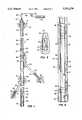
- FIG. 2is a longitudinal central section view of an embodiment of a remotely controllable flow control valve in accordance with the invention
- FIG. 3is a detail section view taken from line 3--3 of FIG. 2;
- FIG. 4is a longitudinal central section view showing a typical arrangement of the remotely controllable flow control valve shown in FIG. 2 disposed in a wellbore.
- U.S. Pat. No. 5,091,725 to Gard and assigned to the assignee of the present inventiondiscloses and claims certain improvements in downhole instrument electromagnetic energy transmitters and receivers.
- U.S. Pat. No. 3,967,201 to Rordenalso describes a wireless subterranean signalling method and system wherein spaced apart transmitter/receiver devices disposed in a well are used for communicating with each other to transmit information regarding wellbore conditions.
- the systems described in these patentsare primarily directed to transmitting data over relatively long distances in the range of several thousand feet. Earth formation conditions can effect the quality and range of the signal. Electromagnetic wave transmission over relatively shorter distances may be carried out using one or more of the systems described above. Moreover, a commercial source of an electromagnetic wave transmitter which may be used in conjunction with the system described in the above-mentioned patent application by Paul A. Fletcher and which may be used in conjunction with the present invention is available from Geoservices, Inc., Houston, Tex.
- FIG. 1there is illustrated a schematic diagram of a multiple well adapted for producing fluids such as crude oil and gas from an earth formation 10 which includes multiple adjacent zones or regions 12 and 14, for example, which are also capable of producing fluids.
- the multiple well shown in FIG. 1is generally designated by the numeral 16 and includes a so-called main wellbore 18 which is suitably completed with a casing 20 and is illustrated as being generally vertical and extending to the surface 11 for termination at a conventional wellhead 22.
- the wellbore 18, typically,may have been initially completed and adapted for production of fluids to the surface by way of a tubing string 26 in a conventional manner.
- the tubing string 26is suitably secured in the casing string 20 by a conventional packer 27 below which the tubing string terminates at a distal end 28.
- One advantageous techniqueis to position a temporary guide or whipstock in the wellbore 18 at a predetermined location, mill out a window, such as windows 30 and 32 in the casing 20 and drill branch wellbores 34 and 36, respectively, away from the main wellbore 18 into the formation zones 14 and 12, respectively, to produce fluids from these zones either after depletion of the zone penetrated by the main wellbore 18 or while fluid is still capable of being produced from the main wellbore.
- the main wellbore 18is adapted to produce fluid from a portion of earth formation 10 penetrated by a wellbore extension portion 19 below the branch wellbore 36.
- the branch wellbores 34 and 36may be completed with liners or casing strings, if formation conditions require same, or these wellbores may be left in the so-called open hole condition in some instances. In either case, after completion of the wellbores 34 and 36, fluids may be produced into the main wellbore 18 for flow through the tubing string 26 to the surface.
- the guide structures or whipstocks used to guide the window mills and the drill motors to create the wellbores 34 and 36require removal from the wellbore 18 after completion of the branch wellbores so that fluid production from all of the wellbores may be unimpeded.
- FIG. 1shows remotely controllable flow control valves, generally designated by the numerals 42, disposed in the wellbores 34, 36 and the main wellbore portion 19, respectively.
- Each of the flow control valves 42is remotely controllable by signal generating means 46 shown disposed in the wellbore portion 40 just below the distal end 28 of the tubing string 26.
- the signal generating means 46preferably comprises a radio frequency range electromagnetic energy transmitter generally of one of the types described above.
- the signal generating means 46may also include a receiver adapted to receive signals in the well 16 from transmitter/receivers associated with each of the valves 42.
- the signal transmitter/receiver 46may be conveyed into the wellbore portion 40 through the tubing string 26 on a multiconductor electrical cable or so-called E-line 48 which is shown connected to a conventional storage reel 50 on the surface.
- the transmitter/receiver 46may be launched into the wellbore 18 through a conventional wireline lubricator 52 connected to the wellhead 22 in a conventional manner.
- a suitable transmitter/receiver controller 54is operably connected to the E-line 48 through the storage reel 50 through known means such as suitable slipring assemblies or the like, not shown.
- a particular advantage in using a transmitter receiver which may be conveyed into the well 16is that the transmitter/receiver 46 may be placed somewhat in proximity to selected ones of the valves 42 for more efficient and error free signal transmission to and from the respective valves.
- One alternate position of the transmitter/receiver 46is shown in FIG. 1.
- the wellbores 34 and 36may intersect the wellbore 18 at widely spaced points in the range of several hundred feet, for example.
- the flow control valve 42 disposed in the wellbore portion 19may be substantially below or spaced from either one of the wellbores 34 and 36.
- branch wellboresmay be sidetracked out of or branch away from the wellbore 18 as required for full production of fluids from the formation 10. Placement of the flow control valves 42 in the branch wellbores, such as the wellbores 34 and 36, reasonably close to the main wellbore 18, will facilitate signal transmission and reception with regard to the transmitter/receiver 46 and suitable receiver or transmitter/receiver means disposed on the respective valves 42.
- FIG. 2there is shown an embodiment of one of the remotely controllable flow control valves 42 characterized by an elongated tubular body 60 having a central fluid flow passage 62 extending therethrough.
- a valve closure member 64is supported in the body 60 for controlling the flow of fluid through the passage 62.
- the closure member 64is shown as a ball-type closure member suitably journalled in the body 60 for rotation about an axis 65 between a fully opened position shown and a fully closed position.
- the ball closure member 64includes a central flow passage 66 formed therein and the closure member is journalled in the body 60 in a conventional manner, details of which are believed to be within the purview of one skilled in the art.
- the closure member 64is movable to open and closed positions and intermediate positions by suitable actuator linkage including a crank arm 68 disposed on the closure member 64, see FIG. 3, and a link 70 connected to a linear actuator 72.
- the actuator 72may, for example, include a linear variable differential transformer or other suitable linear motor which is electrically energizable and operable to selectively position the closure member 64 to throttle the flow of fluid through the passage 62.
- the actuator 72is controllable by a suitable interface or controller 74 operably connected to a radio frequency range receiver 76 disposed in the body 60 and operably connected to a source of electrical energy such as a battery 78. Alternatively, or in addition to the battery 78, a turbine type generator 79 may be interposed in the flow passage 66.
- the interface or controller 74 and the actuator 72may also be suitably connected to the energy source or battery 78.
- the receiver 76may also include signal transmitter means for transmitting radio frequency range signals to the transmitter/receiver 46.
- the valve 42may be configured as an assembly which may be conveyed into the wellbores 34, 36 and the wellbore portion 19 on a wireline and be settable in the wellbores 34, 36 and 19 in a conventional manner.
- the body 60may, for example, be configured similar to a so-called lock mandrel having suitable seal means 80 disposed on the exterior thereof for cooperation with a seal bore member disposed in the respective wellbores.
- Releasable locking dogs 82 of a type used in commercially available wellbore toolsmay be disposed on the body 60 and cooperable with suitable recesses or so-called profiles formed in a landing nipple or the like supported in the respective wellbores by a conventional packer, for example.
- valve 1shows one of the valves 42 disposed in and connected to a landing nipple 86 suitably connected to a conventional packer 88.
- the valve 42 disposed in the wellbore portion 19is operable to control fluid flow through the packer 88, the landing nipple 86 and the valve body into the wellbore portion 40 upon receiving commands from the transmitter/receiver 46.
- the flow control valve 42configured as a releasable lock mandrel or the like, provides for ease of insertion of the valve and retrieval from its working position, if needed. Such action may be required to repair the components mounted on the valve body 60 and replace or recharge the battery 78, for example, if the latter is used without a generator 79.
- a suitable insertion and retrieval head, 61may be operably connected to the body 60 as shown in FIG. 2 for the infrequent retrieval required of the valves 42.
- FIG. 4illustrates one preferred manner of supporting one of the flow control valves 42 in either the wellbore 34 or 36, for example.
- the wellbore 34is illustrated and includes a tubular casing or liner 35. Alternatively, the wellbore 34 may remain in an open hole condition.
- the valve 42is shown disposed in and secured to an elongated nipple member 90 comprising part of a retrievable packer 92 of conventional design. Accordingly, if necessary, the valve 42 may be retrieved from the nipple 90 or the nipple 90 and packer 92 may be retrieved in assembly with the valve 42 disposed therein.
- the retrieval head 61may include suitable antenna means 95, disposed thereon for transmitting electromagnetic wave signals between the transmitter/receiver 46 and the transmitter/receiver 76.
- the retrieval head 61may be of a suitable material adapted to minimize interference of the transmitted signal with respect to the antenna means 95.
- the antenna means 95may be disposed in an extension, not shown, of the body 60.
- the body 60 of the valve 42may need to be extended out of the nipple 90 such that there is minimal interference of the electromagnetic signal being transmitted to and from the antenna means 65, if disposed in the receiving head 61.
- the packer 92may be replaced by an inflatable type packer if used in an open hole type wellbore, for example.
- the valve 42may incorporate certain sensors for determining pressure, temperature, flow rate and fluid composition of fluids flowing through the passage 62 and the transmitter/receiver 76 may be operable to transmit such signals to the transmitter/receiver 46. Accordingly, fluid flow conditions in each of the wellbores 34, 36 and 19 may be monitored when the transmitter/receiver 46 is placed in proximity to and communications are opened between the transmitter/receiver 46 and each one of the valves 42. Each of the transmitter/receivers 76 may be tuned to a predetermined frequency or set of frequencies so that communications are directed between the transmitter/receiver 46 and the valve 42 which is desired to be operated or to be accessed for receipt of fluid flow information.
- Installation of the valves 42may be carried out at the time the wellbores 34, 36 and 19 are completed and in a conventional manner. Once the guides for the respective wellbores 34 and 36 have been removed from the wellbore 18, communication with the valves 42 is carried out through the transmitter/receiver 46 and the respective transmitter/receivers 76 on each valve. Accordingly, fluid flow control may be accomplished with respect to each of the multiple wellbores 19, 34 and 36 and selected ones of the multiple wellbores may be temporarily or permanently shut in if flow conditions from such wellbore or wellbores becomes undesirable.
- By placing the transmitter/receiver 46 in the well 16 in proximity to the respective valve assemblies 42improved signal transmission between the valve assemblies and a controller such as the controller 54 is obtainable. Although surface disposed signal transmission may be attempted in accordance with prior art methods, placement of the transmitter/receiver 46 in selected positions in the main wellbore 18 further assures acceptable communication.
- the present inventionmay be implemented using conventional engineering materials and components generally as described above including the transmitters/receivers 46 and 76 which may be adapted to operate in the manner of the transmitters and receivers of the above-described patents and patent application.
- the transmitters/receivers 46 and 76may also operate on other signal transmission principles including acoustic signals, although interference may be significantly greater due to noise generated by fluid flow and other sources of acoustic signals generated in and around the transmitters/receivers 46 and 76.
- the cable or E-line 48may be replaced by coilable tubing as the conveyor for the transmitter/receiver 46. Such coilable tubing may have suitable electrical conductor means disposed therein, for operating the transmitter/receiver 46 as described, for example, in U.S. Pat. No. 4,685,516 to Smith et al. and assigned to the assignee of the present invention.
Landscapes
- Engineering & Computer Science (AREA)
- Life Sciences & Earth Sciences (AREA)
- Mining & Mineral Resources (AREA)
- Geology (AREA)
- Physics & Mathematics (AREA)
- Environmental & Geological Engineering (AREA)
- Fluid Mechanics (AREA)
- General Life Sciences & Earth Sciences (AREA)
- Geochemistry & Mineralogy (AREA)
- Remote Sensing (AREA)
- Geophysics (AREA)
- Electromagnetism (AREA)
- Geophysics And Detection Of Objects (AREA)
Abstract
Description
The present invention pertains to a system for controlling fluid flow from multiple wellbores which branch off from a main wellbore by signal transmission from a transmitter disposed in the main wellbore to remotely controlled flow control valves disposed in the branch wellbores, respectively.
Production of fluids from subterranean earth formations may be increased by drilling multiple wellbores out of and away from a main wellbore to exploit productions zones which cannot otherwise be effectively connected to the main wellbore. Various techniques have been developed for developing multiple wellbores away from a main wellbore, sometimes known as "side-tracked" or multilaterals, wherein a drill guide or whipstock is placed in the main wellbore at a selected interval and a drill motor, disposed on the end of coilable tubing or on the end of a threaded drill string which may be steerable, is then used to drill a branch wellbore in a direction away from the main wellbore. Several branch wellbores may be drilled away from the main wellbore and completed in a substantially conventional manner by installation of casing or, if the formation conditions permit, the branch wellbores may be left in an "open hole" condition. Since these wellbores are spaced along the main wellbore, fluid communication through the main wellbore to the surface must be provided, which often necessitates the removal of the drill guide equipment or whipstock, once the branch wells are completed. Accordingly, reentry into the branch wellbores from the surface with tools and equipment is difficult and expensive to carry out.
A complication of producing fluids from multiple wellbores which branch out from a main wellbore is that of fluid flow control. One or more of the branch wellbores may cease producing desirable fluids and require to be shut in. In any case, from time to time, testing operations are desired to be carried out to determine the production characteristics of each of the branch wellbores. In this regard, of course, it is conventional to provide a flow control valve at a position in a well which will permit easy access to the valve for operation. In a single wellbore this flow control valve may be placed at or near the surface. However, in multiple wells which extend from a common wellbore, control valves for each well must be placed in each respective branch wellbore. Accordingly, access to these valves to operate same is difficult, if not impossible, to achieve while production continues from one or more of the other wellbores, since placement of tools or retrieval devices normally conveyed into the well on flexible cables, coilable tubing or other mechanical means cannot be easily carried out. Remote control of flow control valves in multiple wells is therefore highly desired and it is to this ,end that the present invention has been developed.
The present invention provides a system for controlling the flow of fluids in multiple wellbores which are sidetracked out of or branch off from a main wellbore in communication with the earth's surface.
In accordance with one aspect of the present invention, a system is provided for controlling fluid flow in multiple wellbores wherein remotely controllable flow control valves are placed in selected ones of multiple wellbores, which control valves include a signal receiver which is adapted to receive signals from a transmitter which may be placed in the main wellbore at or near the respective intersections of the main wellbore with the branch wellbores. The signal transmitter and receiver are preferably operable to generate and receive radio frequency range electromagnetic wave energy.
In accordance with another aspect of the present invention, a wellbore flow control valve is provided which includes a closure member, an actuator, a controller, a signal receiver and a power source including a long-life battery, a downhole generator or both. The flow control valve may include pressure and temperature sensors disposed therein and other fluid flow monitoring means. The signal receiver may be a transmitter and receiver operable to generate signals related to fluid flow characteristics for transmission back to a transmitter/receiver disposed in the main wellbore.
The present invention still further provides an improved method for controlling flow from multiple branch wellbores which are in communication with a main wellbore extending to the earth's surface whereby selected ones of the multiple wellbores, including the main wellbore, may be shut in or have their fluid output or production reduced by a predetermined amount and without requiring entry of surface controlled devices into the branch wellbores. Accordingly, flow control from multiple wells which are sidetracked or branch from a central well may be obtained, selectively.
Those skilled in the art will further appreciate the above-mentioned features and advantages of the present invention together with other superior aspects thereof upon reading the detailed description which follows in conjunction with the drawing.
FIG. 1 is a vertical section view in schematic form of a multiple well including a fluid flow control system in accordance with the invention;
FIG. 2 is a longitudinal central section view of an embodiment of a remotely controllable flow control valve in accordance with the invention;
FIG. 3 is a detail section view taken fromline 3--3 of FIG. 2; and
FIG. 4 is a longitudinal central section view showing a typical arrangement of the remotely controllable flow control valve shown in FIG. 2 disposed in a wellbore.
In the description which follows, like elements are marked throughout the specification and drawing with the same reference numerals, respectively. The drawing figures are not necessarily to scale and certain elements are shown in somewhat generalized and schematic form in the interest of clarity and conciseness.
Several efforts have been made to develop systems for wireless communication between a transmitter/receiver disposed in a deep well and a cooperating transmitter/receiver disposed at or near the earth's surface, primarily for monitoring wellbore conditions. U.S. patent application Ser. No. 08/248,295 filed May 24, 1994 by Paul A. Fletcher and assigned to the assignee of the present invention describes and claims certain improvements in downhole instruments for well operations which utilize a wireless, radio frequency range, electromagnetic energy transmitter and receiver which primarily effects electromagnetic energy transmission through the earth between a deep wellbore and the earth's surface. U.S. Pat. No. 4,691,203 to Rubin et al. describes a transmitter/receiver circuit of the general type referred to hereinabove. U.S. Pat. No. 5,091,725 to Gard and assigned to the assignee of the present invention, discloses and claims certain improvements in downhole instrument electromagnetic energy transmitters and receivers. U.S. Pat. No. 3,967,201 to Rorden also describes a wireless subterranean signalling method and system wherein spaced apart transmitter/receiver devices disposed in a well are used for communicating with each other to transmit information regarding wellbore conditions.
The systems described in these patents are primarily directed to transmitting data over relatively long distances in the range of several thousand feet. Earth formation conditions can effect the quality and range of the signal. Electromagnetic wave transmission over relatively shorter distances may be carried out using one or more of the systems described above. Moreover, a commercial source of an electromagnetic wave transmitter which may be used in conjunction with the system described in the above-mentioned patent application by Paul A. Fletcher and which may be used in conjunction with the present invention is available from Geoservices, Inc., Houston, Tex.
Referring to FIG. 1, there is illustrated a schematic diagram of a multiple well adapted for producing fluids such as crude oil and gas from anearth formation 10 which includes multiple adjacent zones orregions 12 and 14, for example, which are also capable of producing fluids. The multiple well shown in FIG. 1 is generally designated by thenumeral 16 and includes a so-calledmain wellbore 18 which is suitably completed with acasing 20 and is illustrated as being generally vertical and extending to the surface 11 for termination at aconventional wellhead 22. Thewellbore 18, typically, may have been initially completed and adapted for production of fluids to the surface by way of atubing string 26 in a conventional manner. In theexemplary well 16, thetubing string 26 is suitably secured in thecasing string 20 by aconventional packer 27 below which the tubing string terminates at adistal end 28.
In many regions which are capable of producing fluids, such as crude oil and natural gas, it has been considered advantageous to drill multiple branch wellbores out of a main wellbore and several advances in this art have been carried out by the assignee of the present invention. One advantageous technique is to position a temporary guide or whipstock in thewellbore 18 at a predetermined location, mill out a window, such aswindows casing 20 anddrill branch wellbores 34 and 36, respectively, away from themain wellbore 18 into theformation zones 14 and 12, respectively, to produce fluids from these zones either after depletion of the zone penetrated by themain wellbore 18 or while fluid is still capable of being produced from the main wellbore. In other words, themain wellbore 18 is adapted to produce fluid from a portion ofearth formation 10 penetrated by awellbore extension portion 19 below the branch wellbore 36.
Thebranch wellbores 34 and 36 may be completed with liners or casing strings, if formation conditions require same, or these wellbores may be left in the so-called open hole condition in some instances. In either case, after completion of thewellbores 34 and 36, fluids may be produced into themain wellbore 18 for flow through thetubing string 26 to the surface. Typically, the guide structures or whipstocks used to guide the window mills and the drill motors to create thewellbores 34 and 36 require removal from thewellbore 18 after completion of the branch wellbores so that fluid production from all of the wellbores may be unimpeded. Accordingly, once these structures have been removed, reentry into thewellbores 34 and 36 is difficult if not impossible without replacing or reentering the well with a guide or whipstock type device suitably placed to guide tools and equipment into therespective wellbores 34 and 36. Even thewellbore portion 19 may be difficult to reenter since it is not always a true vertical conduit, such as indicated by the schematic of FIG. 1.
The present invention contemplates a solution to the problem of controlling fluid flow from each of thewellbores common wellbore portion 40 below thedistal end 28 of thetubing string 26. FIG. 1 shows remotely controllable flow control valves, generally designated by thenumerals 42, disposed in thewellbores 34, 36 and themain wellbore portion 19, respectively. Each of theflow control valves 42 is remotely controllable bysignal generating means 46 shown disposed in thewellbore portion 40 just below thedistal end 28 of thetubing string 26. The signal generating means 46 preferably comprises a radio frequency range electromagnetic energy transmitter generally of one of the types described above. The signal generating means 46 may also include a receiver adapted to receive signals in thewell 16 from transmitter/receivers associated with each of thevalves 42. The signal transmitter/receiver 46 may be conveyed into thewellbore portion 40 through thetubing string 26 on a multiconductor electrical cable or so-calledE-line 48 which is shown connected to aconventional storage reel 50 on the surface. The transmitter/receiver 46 may be launched into thewellbore 18 through aconventional wireline lubricator 52 connected to thewellhead 22 in a conventional manner.
A suitable transmitter/receiver controller 54 is operably connected to the E-line 48 through thestorage reel 50 through known means such as suitable slipring assemblies or the like, not shown. A particular advantage in using a transmitter receiver which may be conveyed into the well 16 is that the transmitter/receiver 46 may be placed somewhat in proximity to selected ones of thevalves 42 for more efficient and error free signal transmission to and from the respective valves. One alternate position of the transmitter/receiver 46 is shown in FIG. 1. Thewellbores 34 and 36 may intersect thewellbore 18 at widely spaced points in the range of several hundred feet, for example. Theflow control valve 42 disposed in thewellbore portion 19 may be substantially below or spaced from either one of thewellbores 34 and 36. Moreover, several more branch wellbores, not shown, may be sidetracked out of or branch away from thewellbore 18 as required for full production of fluids from theformation 10. Placement of theflow control valves 42 in the branch wellbores, such as thewellbores 34 and 36, reasonably close to themain wellbore 18, will facilitate signal transmission and reception with regard to the transmitter/receiver 46 and suitable receiver or transmitter/receiver means disposed on therespective valves 42.
Referring now to FIG. 2, there is shown an embodiment of one of the remotely controllableflow control valves 42 characterized by an elongatedtubular body 60 having a centralfluid flow passage 62 extending therethrough. Avalve closure member 64 is supported in thebody 60 for controlling the flow of fluid through thepassage 62. Theclosure member 64 is shown as a ball-type closure member suitably journalled in thebody 60 for rotation about anaxis 65 between a fully opened position shown and a fully closed position. Theball closure member 64 includes acentral flow passage 66 formed therein and the closure member is journalled in thebody 60 in a conventional manner, details of which are believed to be within the purview of one skilled in the art.
Theclosure member 64 is movable to open and closed positions and intermediate positions by suitable actuator linkage including acrank arm 68 disposed on theclosure member 64, see FIG. 3, and alink 70 connected to alinear actuator 72. Theactuator 72 may, for example, include a linear variable differential transformer or other suitable linear motor which is electrically energizable and operable to selectively position theclosure member 64 to throttle the flow of fluid through thepassage 62. Theactuator 72 is controllable by a suitable interface orcontroller 74 operably connected to a radiofrequency range receiver 76 disposed in thebody 60 and operably connected to a source of electrical energy such as abattery 78. Alternatively, or in addition to thebattery 78, aturbine type generator 79 may be interposed in theflow passage 66. The interface orcontroller 74 and theactuator 72 may also be suitably connected to the energy source orbattery 78. As mentioned above, thereceiver 76 may also include signal transmitter means for transmitting radio frequency range signals to the transmitter/receiver 46.
Thevalve 42 may be configured as an assembly which may be conveyed into thewellbores 34, 36 and thewellbore portion 19 on a wireline and be settable in thewellbores body 60 may, for example, be configured similar to a so-called lock mandrel having suitable seal means 80 disposed on the exterior thereof for cooperation with a seal bore member disposed in the respective wellbores.Releasable locking dogs 82 of a type used in commercially available wellbore tools may be disposed on thebody 60 and cooperable with suitable recesses or so-called profiles formed in a landing nipple or the like supported in the respective wellbores by a conventional packer, for example. FIG. 1 shows one of thevalves 42 disposed in and connected to alanding nipple 86 suitably connected to aconventional packer 88. Accordingly, thevalve 42 disposed in thewellbore portion 19 is operable to control fluid flow through thepacker 88, the landingnipple 86 and the valve body into thewellbore portion 40 upon receiving commands from the transmitter/receiver 46. Theflow control valve 42, configured as a releasable lock mandrel or the like, provides for ease of insertion of the valve and retrieval from its working position, if needed. Such action may be required to repair the components mounted on thevalve body 60 and replace or recharge thebattery 78, for example, if the latter is used without agenerator 79. Depending on the amount of operation of thevalves 42, however, battery life may extend over a period of years, thereby requiring very infrequent entry into the branch wellbores by insertion and retrieval tools. A suitable insertion and retrieval head, 61, may be operably connected to thebody 60 as shown in FIG. 2 for the infrequent retrieval required of thevalves 42.
FIG. 4 illustrates one preferred manner of supporting one of theflow control valves 42 in either thewellbore 34 or 36, for example. Thewellbore 34 is illustrated and includes a tubular casing orliner 35. Alternatively, thewellbore 34 may remain in an open hole condition. Thevalve 42 is shown disposed in and secured to anelongated nipple member 90 comprising part of aretrievable packer 92 of conventional design. Accordingly, if necessary, thevalve 42 may be retrieved from thenipple 90 or thenipple 90 andpacker 92 may be retrieved in assembly with thevalve 42 disposed therein. Theretrieval head 61 may include suitable antenna means 95, disposed thereon for transmitting electromagnetic wave signals between the transmitter/receiver 46 and the transmitter/receiver 76. Theretrieval head 61 may be of a suitable material adapted to minimize interference of the transmitted signal with respect to the antenna means 95. Alternatively, the antenna means 95 may be disposed in an extension, not shown, of thebody 60. Thebody 60 of thevalve 42 may need to be extended out of thenipple 90 such that there is minimal interference of the electromagnetic signal being transmitted to and from the antenna means 65, if disposed in the receivinghead 61. Thepacker 92 may be replaced by an inflatable type packer if used in an open hole type wellbore, for example.
Thevalve 42 may incorporate certain sensors for determining pressure, temperature, flow rate and fluid composition of fluids flowing through thepassage 62 and the transmitter/receiver 76 may be operable to transmit such signals to the transmitter/receiver 46. Accordingly, fluid flow conditions in each of thewellbores receiver 46 is placed in proximity to and communications are opened between the transmitter/receiver 46 and each one of thevalves 42. Each of the transmitter/receivers 76 may be tuned to a predetermined frequency or set of frequencies so that communications are directed between the transmitter/receiver 46 and thevalve 42 which is desired to be operated or to be accessed for receipt of fluid flow information.
Installation of thevalves 42 may be carried out at the time thewellbores respective wellbores 34 and 36 have been removed from thewellbore 18, communication with thevalves 42 is carried out through the transmitter/receiver 46 and the respective transmitter/receivers 76 on each valve. Accordingly, fluid flow control may be accomplished with respect to each of themultiple wellbores receiver 46 in the well 16 in proximity to therespective valve assemblies 42 improved signal transmission between the valve assemblies and a controller such as thecontroller 54 is obtainable. Although surface disposed signal transmission may be attempted in accordance with prior art methods, placement of the transmitter/receiver 46 in selected positions in themain wellbore 18 further assures acceptable communication.
The present invention may be implemented using conventional engineering materials and components generally as described above including the transmitters/receivers receivers receivers receiver 46. Such coilable tubing may have suitable electrical conductor means disposed therein, for operating the transmitter/receiver 46 as described, for example, in U.S. Pat. No. 4,685,516 to Smith et al. and assigned to the assignee of the present invention.
Although a preferred embodiment of the invention has been described in detail hereinabove, those skilled in the art will recognize that various substitutions and modifications may be made to the invention without departing from the scope and spirit of the appended claims.
Claims (18)
1. A system for controlling fluid flow in a well including at least one wellbore, said system comprising:
a fluid flow control valve interposed in said wellbore for controlling flow of fluid between a predetermined portion of said wellbore and the surface, said flow control valve including a valve closure member, an actuator, a controller and a signal receiver for receiving wireless signals for selectively positioning said closure member to control the flow of fluid through said flow control valve; and
a signal transmitter disposed in said wellbore in a preselected position spaced from said flow control valve and operable to transmit signals to said receiver for operating said flow control valve, at will.
2. The system set forth in claim 1 wherein:
said signal transmitter is connected to means for moving said transmitter into and out of said wellbore and for selectively positioning said transmitter in said wellbore for generating signals to operate said flow control valve.
3. The system set forth in claim 2 wherein:
said transmitter is disposed on conveyor means movable into and out of said wellbore through a wellhead at the surface of an earth formation penetrated by said wellbore.
4. The system set forth in claim 1 wherein:
said transmitter and said receiver are operable to transmit and receive, respectively, electromagnetic wave energy.
5. The system set forth in claim 1 wherein:
said well includes a main wellbore extending from the surface through a portion of an earth formation and multiple wellbores in communication with said main wellbore and extending in different directions from said main wellbore, each of said multiple wellbores including one of said flow control valves disposed therein and said transmitter includes means for selectively controlling respective ones of said flow control valves in said multiple wellbores.
6. A remotely controllable fluid flow control valve for placement in a wellbore for controlling fluid flow through said wellbore, said flow control valve comprising:
a valve body including means for connecting said body to means disposed in said wellbore;
a closure member disposed on said body and operable to control the flow of fluid through a flow passage in said body;
an actuator for moving said closure member between open and closed positions of said passage;
a controller operably connected to said actuator for converting signals received by said flow control valve to signals for causing said actuator to move said closure member;
a receiver disposed on said body and comprising means for receiving electromagnetic wave energy signals; and
an energy source operably connected to said receiver, said controller and said actuator for controlling the movement of said closure member in response to electromagnetic signals being received by said receiver.
7. The flow control valve set forth in claim 6 including:
antenna means operably connected to said body and said receiver for receiving signals transmitted within said wellbore.
8. The valve set forth in claim 7 including:
a retrieval head associated with said body for inserting and retrieving said valve within said wellbore.
9. The valve set forth in claim 8 wherein:
said antenna means is disposed in said retrieval head.
10. The valve set forth in claim 7 including:
releasable lock means disposed on said body and cooperable with means disposed in said wellbore for receiving said flow control valve in a position in said wellbore for controlling the flow of fluid therethrough.
11. In a well penetrating an earth formation including a main wellbore extending within said formation from the earth's surface and at least one branch wellbore extending from the main wellbore to provide at least two wellbores in communication with respective earth formation zones, respective fluid flow control valves disposed in said wellbores for controlling flow of fluid therethrough between said earth formation and said surface, each of said flow control valves including a valve closure member, an actuator, and signal receiver means for receiving wireless signals within said well for selectively operating said flow control valves to control fluid flow therethrough; and
a wireless signal transmitter disposed in said well at a selected point for operating at least one of said flow control valves by transmission of electromagnetic wave energy signals to said receiver means for operation of said closure member, at will.
12. The invention set forth in claim 11 wherein:
said transmitter is connected to means for moving said transmitter into and out of said main wellbore and for selectively positioning said transmitter in said main wellbore for generating signals to operate said flow control valves, respectively.
13. The invention set forth in claim 12 wherein:
said transmitter is disposed on conveyor means movable into and out of said wellbore through a wellhead at the surface of an earth formation penetrated by said wellbore.
14. The invention set forth in claim 11 wherein:
said receiver means are each operable to receive signals of a predetermined characteristic to provide for independent control of said flow control valves, respectively.
15. The invention set forth in claim 11 wherein:
each of said flow control valves includes a controller connected to said actuator; and
an energy source comprising a battery operably connected to said receiver means, said controller and said actuator for controlling the movement of said closure member in response to electromagnetic signals received by said receiver means.
16. The invention set forth in claim 15 including:
antenna means operably connected to said receiver means for receiving signals transmitted within said well.
17. The invention set forth in claim 11 including:
a retrieval head connected to each of said flow control valves for inserting and retrieving said flow control valves within said well, respectively.
18. The invention set forth in claim 11 including:
releasable lock means disposed on said flow control valves and cooperable with means disposed in said wellbores, respectively, for receiving said flow control valves in positions in said wellbores for controlling the flow of fluid therethrough.
Priority Applications (1)
| Application Number | Priority Date | Filing Date | Title |
|---|---|---|---|
| US08/435,784US5531270A (en) | 1995-05-04 | 1995-05-04 | Downhole flow control in multiple wells |
Applications Claiming Priority (1)
| Application Number | Priority Date | Filing Date | Title |
|---|---|---|---|
| US08/435,784US5531270A (en) | 1995-05-04 | 1995-05-04 | Downhole flow control in multiple wells |
Publications (1)
| Publication Number | Publication Date |
|---|---|
| US5531270Atrue US5531270A (en) | 1996-07-02 |
Family
ID=23729795
Family Applications (1)
| Application Number | Title | Priority Date | Filing Date |
|---|---|---|---|
| US08/435,784Expired - LifetimeUS5531270A (en) | 1995-05-04 | 1995-05-04 | Downhole flow control in multiple wells |
Country Status (1)
| Country | Link |
|---|---|
| US (1) | US5531270A (en) |
Cited By (82)
| Publication number | Priority date | Publication date | Assignee | Title |
|---|---|---|---|---|
| US5706896A (en)* | 1995-02-09 | 1998-01-13 | Baker Hughes Incorporated | Method and apparatus for the remote control and monitoring of production wells |
| US5732776A (en)* | 1995-02-09 | 1998-03-31 | Baker Hughes Incorporated | Downhole production well control system and method |
| US5823263A (en)* | 1996-04-26 | 1998-10-20 | Camco International Inc. | Method and apparatus for remote control of multilateral wells |
| US5906238A (en)* | 1996-04-01 | 1999-05-25 | Baker Hughes Incorporated | Downhole flow control devices |
| EP0918136A1 (en)* | 1997-11-24 | 1999-05-26 | Halliburton Energy Services, Inc. | Adjacent well telemetry system and method for use of the same |
| US5960883A (en)* | 1995-02-09 | 1999-10-05 | Baker Hughes Incorporated | Power management system for downhole control system in a well and method of using same |
| US6012015A (en)* | 1995-02-09 | 2000-01-04 | Baker Hughes Incorporated | Control model for production wells |
| US6015012A (en)* | 1996-08-30 | 2000-01-18 | Camco International Inc. | In-situ polymerization method and apparatus to seal a junction between a lateral and a main wellbore |
| GB2340520A (en)* | 1998-08-15 | 2000-02-23 | Schlumberger Ltd | Downhole data acquisition apparatus |
| US6046685A (en)* | 1996-09-23 | 2000-04-04 | Baker Hughes Incorporated | Redundant downhole production well control system and method |
| US6112817A (en)* | 1997-05-06 | 2000-09-05 | Baker Hughes Incorporated | Flow control apparatus and methods |
| US6160492A (en)* | 1998-07-17 | 2000-12-12 | Halliburton Energy Services, Inc. | Through formation electromagnetic telemetry system and method for use of the same |
| US6209649B1 (en) | 1999-08-10 | 2001-04-03 | Camco International, Inc | Selective re-entry tool for multiple tubing completions and method of using |
| US6237683B1 (en) | 1996-04-26 | 2001-05-29 | Camco International Inc. | Wellbore flow control device |
| US6266619B1 (en) | 1999-07-20 | 2001-07-24 | Halliburton Energy Services, Inc. | System and method for real time reservoir management |
| WO2001018357A3 (en)* | 1999-09-07 | 2001-08-02 | Halliburton Energy Serv Inc | Methods and associated apparatus for downhole data retrieval, monitoring and tool actuation |
| WO2001065718A3 (en)* | 2000-03-02 | 2002-03-28 | Shell Oil Co | Wireless power and communications cross-bar switch |
| US20030038734A1 (en)* | 2000-01-24 | 2003-02-27 | Hirsch John Michael | Wireless reservoir production control |
| US20030042026A1 (en)* | 2001-03-02 | 2003-03-06 | Vinegar Harold J. | Controllable production well packer |
| US20030048697A1 (en)* | 2000-03-02 | 2003-03-13 | Hirsch John Michele | Power generation using batteries with reconfigurable discharge |
| US20030066671A1 (en)* | 2000-03-02 | 2003-04-10 | Vinegar Harold J. | Oil well casing electrical power pick-off points |
| US6561277B2 (en)* | 2000-10-13 | 2003-05-13 | Schlumberger Technology Corporation | Flow control in multilateral wells |
| GB2382603A (en)* | 2001-11-28 | 2003-06-04 | Halliburton Energy Serv Inc | Electromagnetic telemetry actuated firing system for well perforating gun |
| US6597175B1 (en) | 1999-09-07 | 2003-07-22 | Halliburton Energy Services, Inc. | Electromagnetic detector apparatus and method for oil or gas well, and circuit-bearing displaceable object to be detected therein |
| US20030150622A1 (en)* | 2002-02-13 | 2003-08-14 | Patel Dinesh R. | Formation isolation valve |
| US6633164B2 (en) | 2000-01-24 | 2003-10-14 | Shell Oil Company | Measuring focused through-casing resistivity using induction chokes and also using well casing as the formation contact electrodes |
| US6633236B2 (en) | 2000-01-24 | 2003-10-14 | Shell Oil Company | Permanent downhole, wireless, two-way telemetry backbone using redundant repeaters |
| US6644110B1 (en) | 2002-09-16 | 2003-11-11 | Halliburton Energy Services, Inc. | Measurements of properties and transmission of measurements in subterranean wells |
| US6662875B2 (en) | 2000-01-24 | 2003-12-16 | Shell Oil Company | Induction choke for power distribution in piping structure |
| US6679332B2 (en) | 2000-01-24 | 2004-01-20 | Shell Oil Company | Petroleum well having downhole sensors, communication and power |
| US20040020657A1 (en)* | 2002-07-31 | 2004-02-05 | Patel Dinesh R. | Multiple interventionless actuated downhole valve and method |
| US20040048596A1 (en)* | 2002-09-10 | 2004-03-11 | Nortel Networks Limited | Method and apparatus for extending high bandwidth communication services to the edge of the network |
| US20040060703A1 (en)* | 2000-01-24 | 2004-04-01 | Stegemeier George Leo | Controlled downhole chemical injection |
| US6715550B2 (en) | 2000-01-24 | 2004-04-06 | Shell Oil Company | Controllable gas-lift well and valve |
| US20040079524A1 (en)* | 2000-01-24 | 2004-04-29 | Bass Ronald Marshall | Toroidal choke inductor for wireless communication and control |
| US6758277B2 (en) | 2000-01-24 | 2004-07-06 | Shell Oil Company | System and method for fluid flow optimization |
| US20040153437A1 (en)* | 2003-01-30 | 2004-08-05 | Buchan John Gibb | Support apparatus, method and system for real time operations and maintenance |
| GB2400620A (en)* | 2002-02-13 | 2004-10-20 | Schlumberger Holdings | A multilateral well completion assembly |
| US6817412B2 (en) | 2000-01-24 | 2004-11-16 | Shell Oil Company | Method and apparatus for the optimal predistortion of an electromagnetic signal in a downhole communication system |
| US6840317B2 (en) | 2000-03-02 | 2005-01-11 | Shell Oil Company | Wireless downwhole measurement and control for optimizing gas lift well and field performance |
| US6840316B2 (en) | 2000-01-24 | 2005-01-11 | Shell Oil Company | Tracker injection in a production well |
| US6851481B2 (en) | 2000-03-02 | 2005-02-08 | Shell Oil Company | Electro-hydraulically pressurized downhole valve actuator and method of use |
| US6853921B2 (en) | 1999-07-20 | 2005-02-08 | Halliburton Energy Services, Inc. | System and method for real time reservoir management |
| US20060131030A1 (en)* | 2004-12-21 | 2006-06-22 | Schlumberger Technology Corporation | Remotely Actuating a Valve |
| US7073594B2 (en) | 2000-03-02 | 2006-07-11 | Shell Oil Company | Wireless downhole well interval inflow and injection control |
| US7114561B2 (en) | 2000-01-24 | 2006-10-03 | Shell Oil Company | Wireless communication using well casing |
| US7147059B2 (en) | 2000-03-02 | 2006-12-12 | Shell Oil Company | Use of downhole high pressure gas in a gas-lift well and associated methods |
| WO2007008351A1 (en)* | 2005-07-13 | 2007-01-18 | Halliburton Energy Services, Inc. | Underbalanced drilling applications hydraulically operated formation isolation valve |
| US20070097091A1 (en)* | 2005-10-28 | 2007-05-03 | Brian Ng | Input Device |
| WO2007049968A1 (en)* | 2005-10-26 | 2007-05-03 | Tomax As | An electric control system for use for activation and position control of rotary valves in an oil well |
| US20070102164A1 (en)* | 2005-11-08 | 2007-05-10 | Baker Hughes Incorporated | Autonomous circulation, fill-up, and equalization valve |
| US20070198223A1 (en)* | 2006-01-20 | 2007-08-23 | Ella Richard G | Dynamic Production System Management |
| US20070285275A1 (en)* | 2004-11-12 | 2007-12-13 | Petrowell Limited | Remote Actuation of a Downhole Tool |
| NO325821B1 (en)* | 2006-03-20 | 2008-07-21 | Well Technology As | Device for acoustic well telemetry with pressure compensated transmitter / receiver units |
| US20080224887A1 (en)* | 2004-07-16 | 2008-09-18 | Sensorwise, Inc. | Seismic Data Acquisition System and Method for Downhole Use |
| US20090020293A1 (en)* | 2007-06-26 | 2009-01-22 | Schlumberger Technology Corporation | Downhole linear actuation apparatus and method |
| US20090145603A1 (en)* | 2007-12-05 | 2009-06-11 | Baker Hughes Incorporated | Remote-controlled gravel pack crossover tool utilizing wired drillpipe communication and telemetry |
| US20100243243A1 (en)* | 2009-03-31 | 2010-09-30 | Schlumberger Technology Corporation | Active In-Situ Controlled Permanent Downhole Device |
| US20100266087A1 (en)* | 2009-04-16 | 2010-10-21 | Searete Llc, A Limited Liability Corporation Of The State Of Delaware | Nuclear fission reactor, flow control assembly, methods therefor and a flow control assembly system |
| US20100266085A1 (en)* | 2009-04-16 | 2010-10-21 | Ahlfeld Charles E | Nuclear fission reactor, flow control assembly, methods therefor and a flow control assembly system |
| WO2010132081A1 (en)* | 2009-04-16 | 2010-11-18 | Searete Llc | Nuclear fission reactor having flow control assembly |
| US20110079402A1 (en)* | 2009-10-02 | 2011-04-07 | Bj Services Company | Apparatus And Method For Directionally Disposing A Flexible Member In A Pressurized Conduit |
| US20110232917A1 (en)* | 2010-03-25 | 2011-09-29 | Halliburton Energy Services, Inc. | Electrically operated isolation valve |
| US20110232916A1 (en)* | 2010-03-25 | 2011-09-29 | Halliburton Energy Services, Inc. | Bi-directional flapper/sealing mechanism and technique |
| US20120305267A1 (en)* | 2011-06-03 | 2012-12-06 | Halliburton Energy Services, Inc. | Wellbore junction completion with fluid loss control |
| US8369474B2 (en) | 2009-04-16 | 2013-02-05 | The Invention Science Fund I, Llc | Nuclear fission reactor, flow control assembly, methods therefor and a flow control assembly system |
| US8490685B2 (en) | 2005-08-19 | 2013-07-23 | Exxonmobil Upstream Research Company | Method and apparatus associated with stimulation treatments for wells |
| US8757274B2 (en) | 2011-07-01 | 2014-06-24 | Halliburton Energy Services, Inc. | Well tool actuator and isolation valve for use in drilling operations |
| US8839856B2 (en) | 2011-04-15 | 2014-09-23 | Baker Hughes Incorporated | Electromagnetic wave treatment method and promoter |
| CN104328831A (en)* | 2014-10-29 | 2015-02-04 | 核工业北京化工冶金研究院 | In-situ leaching uranium mining well field sewage collection system |
| US9121250B2 (en) | 2011-03-19 | 2015-09-01 | Halliburton Energy Services, Inc. | Remotely operated isolation valve |
| EP2929130A4 (en)* | 2013-02-08 | 2016-08-10 | Halliburton Energy Services Inc | VALVE ASSEMBLY THAT CAN BE ACTIVATED WIRELESS |
| US20160312579A1 (en)* | 2014-01-21 | 2016-10-27 | Tendeka As | Downhole flow control device and method |
| US9482072B2 (en) | 2013-07-23 | 2016-11-01 | Halliburton Energy Services, Inc. | Selective electrical activation of downhole tools |
| US9506324B2 (en) | 2012-04-05 | 2016-11-29 | Halliburton Energy Services, Inc. | Well tools selectively responsive to magnetic patterns |
| US9702242B2 (en) | 2013-01-16 | 2017-07-11 | Saudi Arabian Oil Company | Method and apparatus for in-well wireless control using infrasound sources |
| US9739120B2 (en) | 2013-07-23 | 2017-08-22 | Halliburton Energy Services, Inc. | Electrical power storage for downhole tools |
| US9920620B2 (en) | 2014-03-24 | 2018-03-20 | Halliburton Energy Services, Inc. | Well tools having magnetic shielding for magnetic sensor |
| US10262168B2 (en) | 2007-05-09 | 2019-04-16 | Weatherford Technology Holdings, Llc | Antenna for use in a downhole tubular |
| WO2022177802A1 (en)* | 2021-02-22 | 2022-08-25 | Conocophillips Company | Method and apparatus for making a lateral well |
| US11815922B2 (en)* | 2019-10-11 | 2023-11-14 | Schlumberger Technology Corporation | Multiple valve control system and method |
| US20240254862A1 (en)* | 2023-01-31 | 2024-08-01 | Saudi Arabian Oil Company | Controlling fluid flows in a multi-wellbore well system with a surface controlled formation isolation valve |
Citations (10)
| Publication number | Priority date | Publication date | Assignee | Title |
|---|---|---|---|---|
| US3967201A (en)* | 1974-01-25 | 1976-06-29 | Develco, Inc. | Wireless subterranean signaling method |
| US4062379A (en)* | 1976-04-30 | 1977-12-13 | Dowland-Bach Corporation | Safety valve control system for production well |
| US4215746A (en)* | 1979-06-28 | 1980-08-05 | W-K-M Wellhead Systems, Inc. | Pressure responsive safety system for fluid lines |
| US4691203A (en)* | 1983-07-01 | 1987-09-01 | Rubin Llewellyn A | Downhole telemetry apparatus and method |
| US4805657A (en)* | 1988-02-29 | 1989-02-21 | Ferranti Subsea Systems, Inc. | Method and apparatus for remote control of an underwater valve |
| US5091725A (en)* | 1989-08-18 | 1992-02-25 | Atlantic Richfield Company | Well logging tool and system having a switched mode power amplifier |
| US5101907A (en)* | 1991-02-20 | 1992-04-07 | Halliburton Company | Differential actuating system for downhole tools |
| US5127477A (en)* | 1991-02-20 | 1992-07-07 | Halliburton Company | Rechargeable hydraulic power source for actuating downhole tool |
| US5191937A (en)* | 1991-02-22 | 1993-03-09 | Texaco Inc. | Offshore well remote control system |
| US5412568A (en)* | 1992-12-18 | 1995-05-02 | Halliburton Company | Remote programming of a downhole tool |
- 1995
- 1995-05-04USUS08/435,784patent/US5531270A/ennot_activeExpired - Lifetime
Patent Citations (11)
| Publication number | Priority date | Publication date | Assignee | Title |
|---|---|---|---|---|
| US3967201A (en)* | 1974-01-25 | 1976-06-29 | Develco, Inc. | Wireless subterranean signaling method |
| US4062379A (en)* | 1976-04-30 | 1977-12-13 | Dowland-Bach Corporation | Safety valve control system for production well |
| US4215746A (en)* | 1979-06-28 | 1980-08-05 | W-K-M Wellhead Systems, Inc. | Pressure responsive safety system for fluid lines |
| US4691203A (en)* | 1983-07-01 | 1987-09-01 | Rubin Llewellyn A | Downhole telemetry apparatus and method |
| US4805657A (en)* | 1988-02-29 | 1989-02-21 | Ferranti Subsea Systems, Inc. | Method and apparatus for remote control of an underwater valve |
| US5091725A (en)* | 1989-08-18 | 1992-02-25 | Atlantic Richfield Company | Well logging tool and system having a switched mode power amplifier |
| US5101907A (en)* | 1991-02-20 | 1992-04-07 | Halliburton Company | Differential actuating system for downhole tools |
| US5127477A (en)* | 1991-02-20 | 1992-07-07 | Halliburton Company | Rechargeable hydraulic power source for actuating downhole tool |
| US5238070A (en)* | 1991-02-20 | 1993-08-24 | Halliburton Company | Differential actuating system for downhole tools |
| US5191937A (en)* | 1991-02-22 | 1993-03-09 | Texaco Inc. | Offshore well remote control system |
| US5412568A (en)* | 1992-12-18 | 1995-05-02 | Halliburton Company | Remote programming of a downhole tool |
Cited By (157)
| Publication number | Priority date | Publication date | Assignee | Title |
|---|---|---|---|---|
| US5706896A (en)* | 1995-02-09 | 1998-01-13 | Baker Hughes Incorporated | Method and apparatus for the remote control and monitoring of production wells |
| US6012015A (en)* | 1995-02-09 | 2000-01-04 | Baker Hughes Incorporated | Control model for production wells |
| US6192980B1 (en)* | 1995-02-09 | 2001-02-27 | Baker Hughes Incorporated | Method and apparatus for the remote control and monitoring of production wells |
| US6192988B1 (en) | 1995-02-09 | 2001-02-27 | Baker Hughes Incorporated | Production well telemetry system and method |
| US6464011B2 (en) | 1995-02-09 | 2002-10-15 | Baker Hughes Incorporated | Production well telemetry system and method |
| US5732776A (en)* | 1995-02-09 | 1998-03-31 | Baker Hughes Incorporated | Downhole production well control system and method |
| US5941307A (en)* | 1995-02-09 | 1999-08-24 | Baker Hughes Incorporated | Production well telemetry system and method |
| US6176312B1 (en) | 1995-02-09 | 2001-01-23 | Baker Hughes Incorporated | Method and apparatus for the remote control and monitoring of production wells |
| US5960883A (en)* | 1995-02-09 | 1999-10-05 | Baker Hughes Incorporated | Power management system for downhole control system in a well and method of using same |
| US5975204A (en)* | 1995-02-09 | 1999-11-02 | Baker Hughes Incorporated | Method and apparatus for the remote control and monitoring of production wells |
| US6334486B1 (en) | 1996-04-01 | 2002-01-01 | Baker Hughes Incorporated | Downhole flow control devices |
| US6484800B2 (en) | 1996-04-01 | 2002-11-26 | Baker Hughes Incorporated | Downhole flow control devices |
| US6260616B1 (en) | 1996-04-01 | 2001-07-17 | Baker Hughes Incorporated | Downhole flow control devices |
| US6612547B2 (en) | 1996-04-01 | 2003-09-02 | Baker Hughes Incorporated | Downhole flow control devices |
| US5906238A (en)* | 1996-04-01 | 1999-05-25 | Baker Hughes Incorporated | Downhole flow control devices |
| US6450255B2 (en) | 1996-04-01 | 2002-09-17 | Baker Hughes Incorporated | Downhole flow control devices |
| US6494264B2 (en)* | 1996-04-26 | 2002-12-17 | Schlumberger Technology Corporation | Wellbore flow control device |
| US5823263A (en)* | 1996-04-26 | 1998-10-20 | Camco International Inc. | Method and apparatus for remote control of multilateral wells |
| EP1398457A3 (en)* | 1996-04-26 | 2004-09-29 | Schlumberger Technology Corporation | Method and apparatus for remote control of multilateral wells |
| US5927401A (en)* | 1996-04-26 | 1999-07-27 | Camco International Inc. | Method and apparatus for remote control of multilateral wells |
| US6308783B2 (en) | 1996-04-26 | 2001-10-30 | Schlumberger Technology Corporation | Wellbore flow control device |
| US6237683B1 (en) | 1996-04-26 | 2001-05-29 | Camco International Inc. | Wellbore flow control device |
| US5960874A (en)* | 1996-04-26 | 1999-10-05 | Camco International Inc. | Apparatus for remote control of multilateral wells |
| US6015012A (en)* | 1996-08-30 | 2000-01-18 | Camco International Inc. | In-situ polymerization method and apparatus to seal a junction between a lateral and a main wellbore |
| US6046685A (en)* | 1996-09-23 | 2000-04-04 | Baker Hughes Incorporated | Redundant downhole production well control system and method |
| US6112817A (en)* | 1997-05-06 | 2000-09-05 | Baker Hughes Incorporated | Flow control apparatus and methods |
| US6075462A (en)* | 1997-11-24 | 2000-06-13 | Smith; Harrison C. | Adjacent well electromagnetic telemetry system and method for use of the same |
| EP0918136A1 (en)* | 1997-11-24 | 1999-05-26 | Halliburton Energy Services, Inc. | Adjacent well telemetry system and method for use of the same |
| US6160492A (en)* | 1998-07-17 | 2000-12-12 | Halliburton Energy Services, Inc. | Through formation electromagnetic telemetry system and method for use of the same |
| EP0972909A3 (en)* | 1998-07-17 | 2002-11-06 | Halliburton Energy Services, Inc. | Electromagnetic telemetry system |
| GB2340520A (en)* | 1998-08-15 | 2000-02-23 | Schlumberger Ltd | Downhole data acquisition apparatus |
| GB2340520B (en)* | 1998-08-15 | 2000-11-01 | Schlumberger Ltd | Data acquisition apparatus |
| US6462672B1 (en) | 1998-08-15 | 2002-10-08 | Schlumberger Technology Corporation | Data acquisition apparatus |
| USRE42245E1 (en) | 1999-07-20 | 2011-03-22 | Halliburton Energy Services, Inc. | System and method for real time reservoir management |
| USRE41999E1 (en) | 1999-07-20 | 2010-12-14 | Halliburton Energy Services, Inc. | System and method for real time reservoir management |
| US6853921B2 (en) | 1999-07-20 | 2005-02-08 | Halliburton Energy Services, Inc. | System and method for real time reservoir management |
| US6266619B1 (en) | 1999-07-20 | 2001-07-24 | Halliburton Energy Services, Inc. | System and method for real time reservoir management |
| US7079952B2 (en) | 1999-07-20 | 2006-07-18 | Halliburton Energy Services, Inc. | System and method for real time reservoir management |
| US6209649B1 (en) | 1999-08-10 | 2001-04-03 | Camco International, Inc | Selective re-entry tool for multiple tubing completions and method of using |
| US6597175B1 (en) | 1999-09-07 | 2003-07-22 | Halliburton Energy Services, Inc. | Electromagnetic detector apparatus and method for oil or gas well, and circuit-bearing displaceable object to be detected therein |
| US6359569B2 (en) | 1999-09-07 | 2002-03-19 | Halliburton Energy Services, Inc. | Methods and associated apparatus for downhole data retrieval, monitoring and tool actuation |
| US6481505B2 (en) | 1999-09-07 | 2002-11-19 | Halliburton Energy Services, Inc. | Methods and associated apparatus for downhole data retrieval, monitoring and tool actuation |
| US6343649B1 (en) | 1999-09-07 | 2002-02-05 | Halliburton Energy Services, Inc. | Methods and associated apparatus for downhole data retrieval, monitoring and tool actuation |
| US6497280B2 (en) | 1999-09-07 | 2002-12-24 | Halliburton Energy Services, Inc. | Methods and associated apparatus for downhole data retrieval, monitoring and tool actuation |
| WO2001018357A3 (en)* | 1999-09-07 | 2001-08-02 | Halliburton Energy Serv Inc | Methods and associated apparatus for downhole data retrieval, monitoring and tool actuation |
| US6588505B2 (en) | 1999-09-07 | 2003-07-08 | Halliburton Energy Services, Inc. | Methods and associated apparatus for downhole data retrieval, monitoring and tool actuation |
| US6633236B2 (en) | 2000-01-24 | 2003-10-14 | Shell Oil Company | Permanent downhole, wireless, two-way telemetry backbone using redundant repeaters |
| US6679332B2 (en) | 2000-01-24 | 2004-01-20 | Shell Oil Company | Petroleum well having downhole sensors, communication and power |
| US7114561B2 (en) | 2000-01-24 | 2006-10-03 | Shell Oil Company | Wireless communication using well casing |
| US6633164B2 (en) | 2000-01-24 | 2003-10-14 | Shell Oil Company | Measuring focused through-casing resistivity using induction chokes and also using well casing as the formation contact electrodes |
| US20030038734A1 (en)* | 2000-01-24 | 2003-02-27 | Hirsch John Michael | Wireless reservoir production control |
| US6981553B2 (en) | 2000-01-24 | 2006-01-03 | Shell Oil Company | Controlled downhole chemical injection |
| US6662875B2 (en) | 2000-01-24 | 2003-12-16 | Shell Oil Company | Induction choke for power distribution in piping structure |
| US7055592B2 (en) | 2000-01-24 | 2006-06-06 | Shell Oil Company | Toroidal choke inductor for wireless communication and control |
| US7259688B2 (en) | 2000-01-24 | 2007-08-21 | Shell Oil Company | Wireless reservoir production control |
| US6840316B2 (en) | 2000-01-24 | 2005-01-11 | Shell Oil Company | Tracker injection in a production well |
| US6817412B2 (en) | 2000-01-24 | 2004-11-16 | Shell Oil Company | Method and apparatus for the optimal predistortion of an electromagnetic signal in a downhole communication system |
| US20040060703A1 (en)* | 2000-01-24 | 2004-04-01 | Stegemeier George Leo | Controlled downhole chemical injection |
| US6715550B2 (en) | 2000-01-24 | 2004-04-06 | Shell Oil Company | Controllable gas-lift well and valve |
| US20040079524A1 (en)* | 2000-01-24 | 2004-04-29 | Bass Ronald Marshall | Toroidal choke inductor for wireless communication and control |
| US6758277B2 (en) | 2000-01-24 | 2004-07-06 | Shell Oil Company | System and method for fluid flow optimization |
| US7073594B2 (en) | 2000-03-02 | 2006-07-11 | Shell Oil Company | Wireless downhole well interval inflow and injection control |
| US7075454B2 (en) | 2000-03-02 | 2006-07-11 | Shell Oil Company | Power generation using batteries with reconfigurable discharge |
| US20030048697A1 (en)* | 2000-03-02 | 2003-03-13 | Hirsch John Michele | Power generation using batteries with reconfigurable discharge |
| US7170424B2 (en) | 2000-03-02 | 2007-01-30 | Shell Oil Company | Oil well casting electrical power pick-off points |
| WO2001065718A3 (en)* | 2000-03-02 | 2002-03-28 | Shell Oil Co | Wireless power and communications cross-bar switch |
| US6840317B2 (en) | 2000-03-02 | 2005-01-11 | Shell Oil Company | Wireless downwhole measurement and control for optimizing gas lift well and field performance |
| US7147059B2 (en) | 2000-03-02 | 2006-12-12 | Shell Oil Company | Use of downhole high pressure gas in a gas-lift well and associated methods |
| US6851481B2 (en) | 2000-03-02 | 2005-02-08 | Shell Oil Company | Electro-hydraulically pressurized downhole valve actuator and method of use |
| US20030066671A1 (en)* | 2000-03-02 | 2003-04-10 | Vinegar Harold J. | Oil well casing electrical power pick-off points |
| US6868040B2 (en) | 2000-03-02 | 2005-03-15 | Shell Oil Company | Wireless power and communications cross-bar switch |
| RU2256074C2 (en)* | 2000-03-02 | 2005-07-10 | Шелл Интернэшнл Рисерч Маатсхаппий Б.В. | System for controlling connections and feeding of electric current, oil well for extracting oil products (variants) and method for extracting oil product from oil well |
| US6561277B2 (en)* | 2000-10-13 | 2003-05-13 | Schlumberger Technology Corporation | Flow control in multilateral wells |
| US20030042026A1 (en)* | 2001-03-02 | 2003-03-06 | Vinegar Harold J. | Controllable production well packer |
| US7322410B2 (en) | 2001-03-02 | 2008-01-29 | Shell Oil Company | Controllable production well packer |
| US6820693B2 (en) | 2001-11-28 | 2004-11-23 | Halliburton Energy Services, Inc. | Electromagnetic telemetry actuated firing system for well perforating gun |
| GB2382603A (en)* | 2001-11-28 | 2003-06-04 | Halliburton Energy Serv Inc | Electromagnetic telemetry actuated firing system for well perforating gun |
| GB2400620A (en)* | 2002-02-13 | 2004-10-20 | Schlumberger Holdings | A multilateral well completion assembly |
| GB2400620B (en)* | 2002-02-13 | 2005-07-06 | Schlumberger Holdings | Completion assemblies |
| US20030150622A1 (en)* | 2002-02-13 | 2003-08-14 | Patel Dinesh R. | Formation isolation valve |
| US7347272B2 (en)* | 2002-02-13 | 2008-03-25 | Schlumberger Technology Corporation | Formation isolation valve |
| GB2391566B (en)* | 2002-07-31 | 2006-01-04 | Schlumberger Holdings | Multiple interventionless actuated downhole valve and method |
| GB2391566A (en)* | 2002-07-31 | 2004-02-11 | Schlumberger Holdings | Downhole valve with multiple interventionless actuators |
| US20040020657A1 (en)* | 2002-07-31 | 2004-02-05 | Patel Dinesh R. | Multiple interventionless actuated downhole valve and method |
| US6945331B2 (en) | 2002-07-31 | 2005-09-20 | Schlumberger Technology Corporation | Multiple interventionless actuated downhole valve and method |
| US20040048596A1 (en)* | 2002-09-10 | 2004-03-11 | Nortel Networks Limited | Method and apparatus for extending high bandwidth communication services to the edge of the network |
| US6644110B1 (en) | 2002-09-16 | 2003-11-11 | Halliburton Energy Services, Inc. | Measurements of properties and transmission of measurements in subterranean wells |
| US20040153437A1 (en)* | 2003-01-30 | 2004-08-05 | Buchan John Gibb | Support apparatus, method and system for real time operations and maintenance |
| US7584165B2 (en) | 2003-01-30 | 2009-09-01 | Landmark Graphics Corporation | Support apparatus, method and system for real time operations and maintenance |
| US7535795B2 (en) | 2004-07-16 | 2009-05-19 | Sensorwise, Inc. | Seismic data acquisition system and method for downhole use |
| US20080224887A1 (en)* | 2004-07-16 | 2008-09-18 | Sensorwise, Inc. | Seismic Data Acquisition System and Method for Downhole Use |
| US9115573B2 (en) | 2004-11-12 | 2015-08-25 | Petrowell Limited | Remote actuation of a downhole tool |
| US20070285275A1 (en)* | 2004-11-12 | 2007-12-13 | Petrowell Limited | Remote Actuation of a Downhole Tool |
| US8517113B2 (en) | 2004-12-21 | 2013-08-27 | Schlumberger Technology Corporation | Remotely actuating a valve |
| US20060131030A1 (en)* | 2004-12-21 | 2006-06-22 | Schlumberger Technology Corporation | Remotely Actuating a Valve |
| US7597151B2 (en) | 2005-07-13 | 2009-10-06 | Halliburton Energy Services, Inc. | Hydraulically operated formation isolation valve for underbalanced drilling applications |
| WO2007008351A1 (en)* | 2005-07-13 | 2007-01-18 | Halliburton Energy Services, Inc. | Underbalanced drilling applications hydraulically operated formation isolation valve |
| US20070012457A1 (en)* | 2005-07-13 | 2007-01-18 | Curtis Fredrick D | Underbalanced drilling applications hydraulically operated formation isolation valve |
| US8490685B2 (en) | 2005-08-19 | 2013-07-23 | Exxonmobil Upstream Research Company | Method and apparatus associated with stimulation treatments for wells |
| WO2007049968A1 (en)* | 2005-10-26 | 2007-05-03 | Tomax As | An electric control system for use for activation and position control of rotary valves in an oil well |
| US20070097091A1 (en)* | 2005-10-28 | 2007-05-03 | Brian Ng | Input Device |
| US7467665B2 (en) | 2005-11-08 | 2008-12-23 | Baker Hughes Incorporated | Autonomous circulation, fill-up, and equalization valve |
| US20070102164A1 (en)* | 2005-11-08 | 2007-05-10 | Baker Hughes Incorporated | Autonomous circulation, fill-up, and equalization valve |
| US8280635B2 (en) | 2006-01-20 | 2012-10-02 | Landmark Graphics Corporation | Dynamic production system management |
| US20070271039A1 (en)* | 2006-01-20 | 2007-11-22 | Ella Richard G | Dynamic Production System Management |
| US20070198223A1 (en)* | 2006-01-20 | 2007-08-23 | Ella Richard G | Dynamic Production System Management |
| US8195401B2 (en) | 2006-01-20 | 2012-06-05 | Landmark Graphics Corporation | Dynamic production system management |
| NO325821B1 (en)* | 2006-03-20 | 2008-07-21 | Well Technology As | Device for acoustic well telemetry with pressure compensated transmitter / receiver units |
| US10262168B2 (en) | 2007-05-09 | 2019-04-16 | Weatherford Technology Holdings, Llc | Antenna for use in a downhole tubular |
| US8627883B2 (en) | 2007-06-26 | 2014-01-14 | Schlumberger Technology Corporation | Downhole linear actuation apparatus and method |
| US20090020293A1 (en)* | 2007-06-26 | 2009-01-22 | Schlumberger Technology Corporation | Downhole linear actuation apparatus and method |
| US20090145603A1 (en)* | 2007-12-05 | 2009-06-11 | Baker Hughes Incorporated | Remote-controlled gravel pack crossover tool utilizing wired drillpipe communication and telemetry |
| EP2414628A4 (en)* | 2009-03-31 | 2014-08-06 | Services Petroliers Schlumberger | PERMANENT ACTIVE-IN-SITU ACTIVE HOLE DOWNHOLE DEVICE |
| US20100243243A1 (en)* | 2009-03-31 | 2010-09-30 | Schlumberger Technology Corporation | Active In-Situ Controlled Permanent Downhole Device |
| WO2010132081A1 (en)* | 2009-04-16 | 2010-11-18 | Searete Llc | Nuclear fission reactor having flow control assembly |
| US20100266085A1 (en)* | 2009-04-16 | 2010-10-21 | Ahlfeld Charles E | Nuclear fission reactor, flow control assembly, methods therefor and a flow control assembly system |
| KR20110138268A (en)* | 2009-04-16 | 2011-12-26 | 시리트 엘엘씨 | Nuclear Fission Reactor with Flow Control Assembly |
| US10839965B2 (en) | 2009-04-16 | 2020-11-17 | Terrapower, Llc | Nuclear fission reactor, flow control assembly, methods therefor and a flow control assembly system |
| US20100266087A1 (en)* | 2009-04-16 | 2010-10-21 | Searete Llc, A Limited Liability Corporation Of The State Of Delaware | Nuclear fission reactor, flow control assembly, methods therefor and a flow control assembly system |
| US8320513B2 (en) | 2009-04-16 | 2012-11-27 | The Invention Science Fund I, Llc | Nuclear fission reactor, flow control assembly, methods therefor and a flow control assembly system |
| CN102460595A (en)* | 2009-04-16 | 2012-05-16 | 希尔莱特有限责任公司 | Nuclear Fission Reactor with Flow Control Components |
| US8369474B2 (en) | 2009-04-16 | 2013-02-05 | The Invention Science Fund I, Llc | Nuclear fission reactor, flow control assembly, methods therefor and a flow control assembly system |
| RU2537690C2 (en)* | 2009-04-16 | 2015-01-10 | Сирит ЭлЭлСи | Nuclear fission reactor having flow control assembly |
| RU2532530C2 (en)* | 2009-04-16 | 2014-11-10 | Сирит ЭлЭлСи | Fission nuclear reactor having flow control assembly |
| CN102460595B (en)* | 2009-04-16 | 2014-09-24 | 泰拉能源有限责任公司 | Nuclear Fission Reactor with Flow Control Components |
| WO2010132084A3 (en)* | 2009-04-16 | 2011-01-27 | Searete Llc | Nuclear fission reactor having flow control assembly |
| US20100266088A1 (en)* | 2009-04-16 | 2010-10-21 | Searete Llc, A Limited Liability Corporation Of The State Of Delaware | Nuclear fission reactor, flow control assembly, methods therefor and a flow control assembly system |
| US8528651B2 (en) | 2009-10-02 | 2013-09-10 | Baker Hughes Incorporated | Apparatus and method for directionally disposing a flexible member in a pressurized conduit |
| US20110079402A1 (en)* | 2009-10-02 | 2011-04-07 | Bj Services Company | Apparatus And Method For Directionally Disposing A Flexible Member In A Pressurized Conduit |
| US8230934B2 (en) | 2009-10-02 | 2012-07-31 | Baker Hughes Incorporated | Apparatus and method for directionally disposing a flexible member in a pressurized conduit |
| US8733448B2 (en) | 2010-03-25 | 2014-05-27 | Halliburton Energy Services, Inc. | Electrically operated isolation valve |
| US8689885B2 (en) | 2010-03-25 | 2014-04-08 | Halliburton Energy Services, Inc. | Bi-directional flapper/sealing mechanism and technique |
| US20110232917A1 (en)* | 2010-03-25 | 2011-09-29 | Halliburton Energy Services, Inc. | Electrically operated isolation valve |
| US20110232916A1 (en)* | 2010-03-25 | 2011-09-29 | Halliburton Energy Services, Inc. | Bi-directional flapper/sealing mechanism and technique |
| US9121250B2 (en) | 2011-03-19 | 2015-09-01 | Halliburton Energy Services, Inc. | Remotely operated isolation valve |
| US8839856B2 (en) | 2011-04-15 | 2014-09-23 | Baker Hughes Incorporated | Electromagnetic wave treatment method and promoter |
| US20120305267A1 (en)* | 2011-06-03 | 2012-12-06 | Halliburton Energy Services, Inc. | Wellbore junction completion with fluid loss control |
| US9200482B2 (en)* | 2011-06-03 | 2015-12-01 | Halliburton Energy Services, Inc. | Wellbore junction completion with fluid loss control |
| US10202824B2 (en) | 2011-07-01 | 2019-02-12 | Halliburton Energy Services, Inc. | Well tool actuator and isolation valve for use in drilling operations |
| US8757274B2 (en) | 2011-07-01 | 2014-06-24 | Halliburton Energy Services, Inc. | Well tool actuator and isolation valve for use in drilling operations |
| US9506324B2 (en) | 2012-04-05 | 2016-11-29 | Halliburton Energy Services, Inc. | Well tools selectively responsive to magnetic patterns |
| US9702242B2 (en) | 2013-01-16 | 2017-07-11 | Saudi Arabian Oil Company | Method and apparatus for in-well wireless control using infrasound sources |
| US10100608B2 (en) | 2013-02-08 | 2018-10-16 | Halliburton Energy Services, Inc. | Wireless activatable valve assembly |
| EP2929130A4 (en)* | 2013-02-08 | 2016-08-10 | Halliburton Energy Services Inc | VALVE ASSEMBLY THAT CAN BE ACTIVATED WIRELESS |
| US9540912B2 (en) | 2013-02-08 | 2017-01-10 | Halliburton Energy Services, Inc. | Wireless activatable valve assembly |
| US9482072B2 (en) | 2013-07-23 | 2016-11-01 | Halliburton Energy Services, Inc. | Selective electrical activation of downhole tools |
| US9739120B2 (en) | 2013-07-23 | 2017-08-22 | Halliburton Energy Services, Inc. | Electrical power storage for downhole tools |
| US20160312579A1 (en)* | 2014-01-21 | 2016-10-27 | Tendeka As | Downhole flow control device and method |
| US11434722B2 (en)* | 2014-01-21 | 2022-09-06 | Tendeka As | Downhole flow control device and method |
| US9920620B2 (en) | 2014-03-24 | 2018-03-20 | Halliburton Energy Services, Inc. | Well tools having magnetic shielding for magnetic sensor |
| CN104328831B (en)* | 2014-10-29 | 2016-06-01 | 核工业北京化工冶金研究院 | A kind of ground-dipping uranium extraction well site sewage collection system |
| CN104328831A (en)* | 2014-10-29 | 2015-02-04 | 核工业北京化工冶金研究院 | In-situ leaching uranium mining well field sewage collection system |
| US11815922B2 (en)* | 2019-10-11 | 2023-11-14 | Schlumberger Technology Corporation | Multiple valve control system and method |
| WO2022177802A1 (en)* | 2021-02-22 | 2022-08-25 | Conocophillips Company | Method and apparatus for making a lateral well |
| US12129741B2 (en) | 2021-02-22 | 2024-10-29 | Conocophillips Company | Method and apparatus for making a lateral well |
| US20240254862A1 (en)* | 2023-01-31 | 2024-08-01 | Saudi Arabian Oil Company | Controlling fluid flows in a multi-wellbore well system with a surface controlled formation isolation valve |
| US12392221B2 (en)* | 2023-01-31 | 2025-08-19 | Saudi Arabian Oil Company | Controlling fluid flows in a multi-wellbore well system with a surface controlled formation isolation valve |
Similar Documents
| Publication | Publication Date | Title |
|---|---|---|
| US5531270A (en) | Downhole flow control in multiple wells | |
| US5941307A (en) | Production well telemetry system and method | |
| US5887657A (en) | Pressure test method for permanent downhole wells and apparatus therefore | |
| US6006832A (en) | Method and system for monitoring and controlling production and injection wells having permanent downhole formation evaluation sensors | |
| US5706896A (en) | Method and apparatus for the remote control and monitoring of production wells | |
| US5662165A (en) | Production wells having permanent downhole formation evaluation sensors | |
| US5730219A (en) | Production wells having permanent downhole formation evaluation sensors | |
| US7228902B2 (en) | High data rate borehole telemetry system | |
| US9249648B2 (en) | Continuous circulation and communication drilling system | |
| US6046685A (en) | Redundant downhole production well control system and method | |
| US5597042A (en) | Method for controlling production wells having permanent downhole formation evaluation sensors | |
| US5803167A (en) | Computer controlled downhole tools for production well control | |
| US8469084B2 (en) | Wireless transfer of power and data between a mother wellbore and a lateral wellbore | |
| US6095248A (en) | Method and apparatus for remote control of a tubing exit sleeve | |
| CA2127921A1 (en) | Method and apparatus for electric/acoustic telemetry | |
| GB2323109A (en) | Power management system for downhole control system in a well | |
| US10801320B2 (en) | Methods and systems for downhole inductive coupling | |
| EP1250514B1 (en) | Downhole wireless two-way telemetry system | |
| CA2187424C (en) | Method and apparatus for the remote control and monitoring of production wells |
Legal Events
| Date | Code | Title | Description |
|---|---|---|---|
| AS | Assignment | Owner name:ATLANTIC RICHFIELD COMPANY, CALIFORNIA Free format text:ASSIGNMENT OF ASSIGNORS INTEREST;ASSIGNORS:FLETCHER, PAUL A.;WALZ, GREGORY S.;REEL/FRAME:007509/0933;SIGNING DATES FROM 19950404 TO 19950501 | |
| STCF | Information on status: patent grant | Free format text:PATENTED CASE | |
| FPAY | Fee payment | Year of fee payment:4 | |
| AS | Assignment | Owner name:PHILLIPS PETROLEUM COMPANY, OKLAHOMA Free format text:ASSIGNMENT OF ASSIGNORS INTEREST;ASSIGNOR:ATLANTIC RICHFIELD COMPANY;REEL/FRAME:012333/0329 Effective date:20010920 | |
| FPAY | Fee payment | Year of fee payment:8 | |
| FPAY | Fee payment | Year of fee payment:12 | |
| AS | Assignment | Owner name:CONOCOPHILLIPS COMPANY, TEXAS Free format text:CHANGE OF NAME;ASSIGNOR:PHILLIPS PETROLEUM COMPANY;REEL/FRAME:022793/0106 Effective date:20021212 |