US5531252A - Vacuum fill system - Google Patents
Vacuum fill systemDownload PDFInfo
- Publication number
- US5531252A US5531252AUS08/485,710US48571095AUS5531252AUS 5531252 AUS5531252 AUS 5531252AUS 48571095 AUS48571095 AUS 48571095AUS 5531252 AUS5531252 AUS 5531252A
- Authority
- US
- United States
- Prior art keywords
- hollow container
- container
- vacuum
- hollow
- sectional area
- Prior art date
- Legal status (The legal status is an assumption and is not a legal conclusion. Google has not performed a legal analysis and makes no representation as to the accuracy of the status listed.)
- Expired - Lifetime
Links
- 239000000463materialSubstances0.000claimsabstractdescription142
- 230000009969flowable effectEffects0.000claimsabstractdescription98
- 210000002445nippleAnatomy0.000claimsdescription16
- 229910001220stainless steelInorganic materials0.000claimsdescription3
- 239000010935stainless steelSubstances0.000claimsdescription3
- 239000007787solidSubstances0.000claims15
- 230000001276controlling effectEffects0.000claims12
- 230000001105regulatory effectEffects0.000claims1
- 239000000428dustSubstances0.000description15
- 238000000034methodMethods0.000description7
- 238000005056compactionMethods0.000description6
- 239000002245particleSubstances0.000description6
- 230000009471actionEffects0.000description4
- 230000008569processEffects0.000description4
- 238000012856packingMethods0.000description3
- 230000002265preventionEffects0.000description3
- 230000035939shockEffects0.000description3
- 238000004581coalescenceMethods0.000description2
- 239000012611container materialSubstances0.000description2
- 230000007423decreaseEffects0.000description2
- 238000005429filling processMethods0.000description2
- 230000002427irreversible effectEffects0.000description2
- QSHDDOUJBYECFT-UHFFFAOYSA-NmercuryChemical compound[Hg]QSHDDOUJBYECFT-UHFFFAOYSA-N0.000description2
- 229910052753mercuryInorganic materials0.000description2
- 235000013606potato chipsNutrition0.000description2
- 238000011084recoveryMethods0.000description2
- 230000000717retained effectEffects0.000description2
- 239000000126substanceSubstances0.000description2
- 238000013022ventingMethods0.000description2
- 238000005273aerationMethods0.000description1
- 230000008901benefitEffects0.000description1
- 238000004891communicationMethods0.000description1
- 239000000203mixtureSubstances0.000description1
- 238000012986modificationMethods0.000description1
- 230000004048modificationEffects0.000description1
- 238000004806packaging method and processMethods0.000description1
- 230000000704physical effectEffects0.000description1
- 230000008707rearrangementEffects0.000description1
- 239000002699waste materialSubstances0.000description1
Images


Classifications
- B—PERFORMING OPERATIONS; TRANSPORTING
- B65—CONVEYING; PACKING; STORING; HANDLING THIN OR FILAMENTARY MATERIAL
- B65B—MACHINES, APPARATUS OR DEVICES FOR, OR METHODS OF, PACKAGING ARTICLES OR MATERIALS; UNPACKING
- B65B1/00—Packaging fluent solid material, e.g. powders, granular or loose fibrous material, loose masses of small articles, in individual containers or receptacles, e.g. bags, sacks, boxes, cartons, cans, or jars
- B65B1/20—Reducing volume of filled material
- B65B1/26—Reducing volume of filled material by pneumatic means, e.g. suction
Definitions
- This inventionrelates to a vacuum fill system for dearating flowable materials for storage in a container, and in particular, to a vacuum fill system for deaerating and compacting flowable materials used in flexible bulk containers.
- Containers used in the storage, transportation, and dispensation of flowable materialshave been around for as long as civilization itself.
- the use of such containershas always been limited by (1) the weight, density, and other physical properties of the material being stored, and (2) by the process and type of container used to store the material.
- the shipment of smaller sized containers using vacuum sealed packages, such as vacuum sealed coffee containers,has alleviated many of the above problems of cost and time.
- the present inventionsubstantially eliminates settling and the inherent problems associated therewith by providing a vacuum filling system that deaerates the flowable material during filling.
- the present inventionthus allows more product to be transported in the same size container than is possible using prior techniques.
- the present inventionallows for the far more efficient total use of all of the container materials and space.
- the vacuum fill system of the present inventiongenerally comprises a hollow container for holding the flowable material; a device for controlling the flow of the flowable material into the hollow container; an apparatus for creating a vacuum in the hollow container for deaerating the flowable materials and for compacting the deaerated materials; and a device for controlling the flow of the deaerated, compacted flowable material from the first container into a storage container for shipment.
- a first conventional full opening ball or gate valveis located at one end of the hollow container for controlling the flow of flowable materials into the first container.
- a conventional vacuum pumpcapable of pulling a vacuum of eighteen (18) inches of mercury for deaerating the flowable materials, is connected to the hollow container through a series of valves and vacuum lines.
- a second conventional full opening ball or gate valveis located at the opposite end of the hollow container for controlling the flow of deaerated flowable material into the shipping container.
- flowable materialis fed into the hollow cylindrical container.
- a vacuumis created through the use of a plurality of valves and a conventional vacuum pump. After sufficient deaeration of the flowable material is achieved, the vacuum is released and the interior of the hollow container is returned to atmospheric pressure substantially, instantaneously causing the material to compact in a direction parallel to the axis of symmetry of the hollow container. The compacted, deaerated flowable material then drops from the first container into a flexible container for shipment.
- the hollow cylindrical containerincorporates tapered sidewalls.
- tapered sidewallsassist in the prevention of sticking of the compacted deaerated flowable material in the hollow cylindrical container.
- compressed airis introduced into the first container to force the compacted, deaerated flowable material from the first container into the flexible container.
- the hollow cylindrical containercomprises an upper section with a substantially vertical sidewall and a lower section with a tapered sidewall.
- the two profile configurations for the sidewall in the hollow containerincorporate the advantage of a straight profile in the upper portion, which provides for additional volume in the container, and a tapered profile in the lower portion, which assists in the prevention of sticking of the compacted deaerated flowable material.
- the hollow container of the third embodimentis preferably formed from stainless steel which is polished internally. The choice of material and polished finish further assist in the prevention of sticking of the compacted deaerated flowable material in the container.
- the third embodimentprovides the additional feature of a baffle plate installed in the upper section of the hollow container. This baffle plate assists in evenly distributing the shock wave created by returning the first container to atmospheric pressure.
- the present inventionprovides for more utilization of the flexible container, eliminating wasted space and allowing for the shipment of more material without any increase in the container volume.
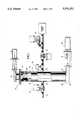
- FIG. 1is a partial sectional view of the vacuum fill system
- FIG. 2is a partial sectional view of the vacuum fill system illustrating its use with semi-bulk bags used for containing flowable materials;
- FIG. 3is a partial sectional view of the vacuum fill system illustrating the filling of the hollow container with flowable material before deaerating;
- FIG. 4is a partial sectional view of the vacuum fill system illustrating the deaerated flowable material
- FIG. 5is a partial sectional view of the vacuum fill system illustrating the deaerated flowable material inside the storage container
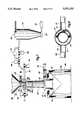
- FIG. 6is a partial sectional view of a second embodiment of the invention.
- FIG. 7is a partial sectional view of a third embodiment of the invention.
- FIG. 8is a plain view of a baffle plate located in the hollow container.
- the vacuum fill system 10has a hollow, cylindrical container 20, having inner and outer chambers 22 and 24, respectively. Chambers 22 and 24 have first and second ends 26 and 28.
- the inner chamber 22connects with the outer chamber 24 at the first end 26 of the two chambers.
- the inner chamber 22has a plurality of openings 30 which allow for the venting of air during use.
- a conventional knife or slide gate valve 32 and associated air cylinder 34Attached to the first end 26 of the hollow, cylindrical container 20 and its inner and outer chambers 22 and 24 is a conventional knife or slide gate valve 32 and associated air cylinder 34 which controls the opening and closing of the gate 32.
- the slide gate valve 32 and air cylinder 34are of conventional types well known in the art. When the gate valve 32 is in the open position, flowable material flows through the gate valve 32 and into inner chamber 22 of the hollow, cylindrical container 20.
- a second slide or knife gate valve 36which is normally of a slightly larger diameter than slide gate valve 32.
- the slide gate valve 36also has associated with it an air cylinder 38 and switch 40, both well known in the art, which are utilized to fully open or close the slide gate valve 36 to allow compacted materials to exit from the hollow, cylindrical container 20 after deaeration and compaction.
- a gap 42between the bottom of the inner chamber 22 and outer chamber 24 of the container 20. The gap 42 allows air to vent and is utilized to help form a vacuum during the deaeration process.
- the outer chamber 24 of the hollow, cylindrical container 20has a plurality of openings 44 into which vacuum lines 46 run.
- the vacuum lines 46do not, however, connect to the inner chamber 22.
- One of the vacuum lines 46is connected to a solenoid actuated butterfly valve 48 which in turn connects to a conventional dust collector (not shown).
- the second vacuum line 46is connected to a series of solenoid actuated butterfly valves 50 and 52, and from there to a conventional vacuum pump (not shown).
- the vacuum pumpmust be capable of pulling a minimum of eighteen (18) inches of mercury during operation.
- a conventional pressure switch 54is Also connected to the second vacuum line 46, which is utilized to control the opening and closing of the valves 50 and 52.
- FIGS. 2 through 5illustrate the operation of the vacuum fill system of the present invention.
- the vacuum fill system 10illustrated in FIGS. 2 through 5
- the present inventionis capable of being utilized with any type of container no matter how large or small where it is desired to compact, deaerate and densify the flowable materials for packing into a container for shipment and storage.
- FIG. 2therein is illustrated the initial start up position of the vacuum fill system 10.
- valves 32, 36, 48, 50 and 52are closed.
- the flowable material 56is contained within a conventional holding/storage device 58, such as a hopper.
- the vacuum fill system 10is connected to a semi-bulk bag 60 through conventional means.
- FIG. 3therein it is shown that the hollow, cylindrical container 20 has been filled with flowable material 56.
- valves 32 and 48have been opened. This results in the opening of slide gate valve 32 and the venting of air through valve 48 to the dust collector during the filling process.
- the flowable materialfills the inner chamber 22 up to the level of the openings 30. Openings 30 and gap 42 allow the dust to be vented to the dust collector through valve 48 and vacuum lines 46.
- valve 32automatically closes preventing the flow of further flowable material 56 into the inner chamber 22 of the hollow, cylindrical container 20.
- valve 48is closed automatically and valve 50 is opened. This creates a vacuum in the space between the inner and outer chambers 22 and 24.
- FIG. 4therein is illustrated that the flowable material 56 has been deaerated and compacted and that the volume of material 56 is now significantly less than when first introduced into the hollow, cylindrical container 20.
- the volume of flowable material 56actually increases slightly as the internal air passes through it and the vacuum is created. Thus, there is actually a volume gain until the chamber is returned to atmospheric pressure.
- valve 52is opened immediately. Valve 52 must be opened suddenly and fully in order to get a high impact on the material 56 from the entering air. The impact of the entering air compresses and compacts the deaerated, flowable material 56, both axially and radially, due to the internal low pressure previously created by the vacuum.
- valve 36is opened and the compacted, deaerated flowable material 56 flows as a compact "slug" of material into the desired container or, as illustrated, bulk bag 60. Since the compacted and deaerated material is highly densified and only drops a short distance before entering the container 60, there is very little chance of reaeration.
- slide gate valve 36closes and the vacuum fill system 10 is ready to begin a new cycle.
- a second embodiment of the vacuum fill system 100has a hollow, tapered container 120 having a first end 122 and a second end 124. Attached to the first end 122 of the hollow, tapered container 120 is a conventional knife or slide gate valve 126 and an associated air cylinder 128 which controls the opening and closing of the slide gate valve 126.
- the slide gate valve 126 and the air cylinder 128are of conventional types well known in the art. When the slide gate valve 126 is in the open position, flowable materials flow from an input source 130 through the slide gate valve 126 into the hollow, tapered container 120.
- a second knife or slide gate valve 132At the second end 124 of the hollow, tapered container 120, there is a second knife or slide gate valve 132.
- An associated air cylinder 134 and a switch 136are utilized to open or close the slide gate valve 132 to allow flowable materials to exit the hollow, tapered container 120 through a discharge chute 138 after deaeration and compaction.
- the slide gate valve 132, the air cylinder 134 and the switch 136are of conventional types well known in the art.
- Line 140runs into an opening 142 in the hollow, tapered container 120 and is connected to a solenoid actuated butterfly valve 144 which is in turn connected to a compressed air source (not shown).
- a vacuum line 141runs into an opening 143 in the hollow, tapered container 120, and is connected to a series of solenoid actuated butterfly valves 146, 148, and 150, and from there to a conventional dust collector 152.
- the dust collector 152has a knife or slide gate valve 151 and an associated air cylinder 153 to allow discharge of dust and particles from the dust collector.
- Mounted on top of the dust collectoris a fan 155.
- Connected to the vacuum line 141 on both sides of the butterfly valve 150is a vacuum pump or high vacuum venturi 154.
- the vacuum fill system 100is preferably used in connection with the filling of a semi-bulk container for handling flowable materials, it must be understood that the vacuum fill system 100 is capable of being utilized with any type of container, no matter how large or small, where it is desired to compact, deaerate, and densify the flowable materials for packing into a container for shipment and storage.
- a semi-bulk bag 156is connected to the vacuum fill system 100 through conventional means such as hooks 157 mounted in a frame 159.
- Support loops 161 on the bag 156are placed over the hooks 157 to suspend the bag below the discharge chute 138.
- a collar 163 on the bag 156is placed around the discharge chute 138 to prevent spillage while filling the bag 156.
- the slide gate valves 126 and 132 and the solenoid actuated butterfly valves 144, 146, and 150are closed to allow evacuation of air from the container 120.
- the slide gate valve 126is then opened to fill the hollow, tapered container 120 with flowable material.
- the slide gate valve 126is then closed, the valve 148 remains open and the valve 150 is opened to initiate evacuation of air from the filled tapered chamber 120.
- the valves 146 and 150are closed and the valve 148 remains open drawing air from the chamber 120 through action of the vacuum pump or high vacuum venturi 154.
- the valve 148is closed and the valve 146 is opened to suddenly vent vacuum line 141 and the tapered container 120 to the atmosphere.
- Pressure wavesare generated near the upper surface of the container 120 which forces the particles at the top to move downwardly, thereby compressing the small amount of air remaining adjacent the particles at the wave front.
- the wall of the container 120prevents the loss of energy in the radial direction, and directs all motion parallel to the axis of symmetry of the container 120.
- the volume of the flowable materialdecreases in such a way that increasing pressure waves propagate at faster speeds, thereby causing a shock wave to form from the coalescence of many weaker pressure waves.
- the slide gate valve 132 and the valve 144are then opened to allow compressed air to be injected into the tapered container 120, thereby forcing the flowable materials as a compact "slug" of material from the tapered container 120 and into the desired receiving container or, as illustrated, bulk bag 156.
- the slide gate valve 132closes and the vacuum fill system 100 is ready to begin a new cycle.
- a third embodiment of the vacuum fill system 200has a hollow container 220 having a first end 222 and a second end 224.
- the hollow containerfurther includes a top section 221 with a substantially vertical sidewall and a lower section 223 with a downward and outwardly tapered sidewall.
- the hollow containeris preferably formed from stainless steel and polished on the inside.
- Attached to the first end 222 of the hollow container 220is a full opening ball or gate valve 226 and an actuator 228 which controls the opening and closing of the valve 226.
- the valve 226 and the actuator 228are of conventional types well known in the art.
- Attached to the lower face of the valveis a tubular nipple 225 of the same diameter as the opening in the gate valve.
- the tubular nipple 225extends into the upper section of the hollow container.
- An annular spaceis created between the tubular nipple 225 and the upper interior side wall of the hollow container.
- One or more openingsare present in the side wall of the tubular nipple and provide communication between the interior of the nipple and the annular space between the nipple and the sidewall of the hollow container.
- a second full opening ball or gate valve 232At the second end 224 of the hollow container 220, there is a second full opening ball or gate valve 232.
- An associated actuator 234 and a switch 236are utilized to fully open or close the valve 232 to allow compacted materials to exit the hollow, tapered container 220 through a discharge chute 238 after deaeration and compaction.
- the valve 232, the actuator 234 and the switch 236are of conventional types well known in the art.
- Line 240runs into an opening 242 in the hollow container 220 and is connected to a solenoid actuated valve 244, which in turn is connected to a compressed air source (not shown).
- a vacuum line 241runs into an opening 243 in the hollow container 220 and is connected to a series of solenoid actuated valves 246, 248, and 250, and from there to a conventional dust collector 252.
- the dust collector 252has a full opening valve 251 and an actuator 253 to allow discharge of dust and particles from the dust collector.
- Mounted on top of the dust collectoris a fan 255.
- Connected to the vacuum line 241 on both sides of the butterfly valve 250is a vacuum pump or high vacuum venturi 254.
- a half circle baffle 227is attached to the tubular nipple 225 and positioned slightly below opening 242 and in the annular space between the tubular nipple 225 and the hollow container side wall.
- the vacuum fill system 200is preferably used in connection with the filling of a semi-bulk container for handling flowable materials, it must be understood that the vacuum fill system 200 is capable of being utilized with any type of container, no matter how large or small, where it is desired to compact, deaerate, and densify the flowable materials for packing into a container for shipment and storage.
- a semi-bulk bag 256is connected to the vacuum fill system 200 through conventional means such as hooks 257 mounted in a frame 259. Support loops 261 on the bag 256 are placed over the hooks 257 to suspend the bag below the discharge chute 238. A collar 263 on the bag 256 is placed around the discharge chute 238 to prevent spillage while filling the bag 256.
- valves 232, 244 and 246are closed. Valves 226, 248 and 250 are opened. Air is vented through valves 248 and 250 to the dust collector 252. The volume of flowable material fed into the hollow container is controlled by either weight or height. When a predetermined volume is reached, valve 226 is then closed. To further evacuate the filled chamber 220, the valve 250 is closed and valve 248 remains open drawing air from the container 220 through action of the vacuum pump or high vacuum venturi 254.
- the valve 248is closed and the valve 246 is opened to suddenly vent vacuum line 241 and the hollow container 220 to the atmosphere.
- Pressure wavesare generated near the upper surface of the hollow container 220 which force the particles at the top to move downwardly, thereby compressing the small amount of air remaining adjacent the particles at the wave front.
- the wall of the container 220prevents the loss of energy in the radial direction, and directs all motion parallel to the axis of symmetry of the container 220.
- the half circle baffle 227distributes the pressure wave around tubular nipple 225 providing for more even compaction in the container.
- the volume of the flowable materialdecreases in such a way that increasing pressure waves propagate at faster speeds, thereby causing a shock wave to form from the coalescence of many weaker pressure waves.
- a reflected waveis generated which propagates back up through the material causing additional compaction.
- the action of these wavesis non-isotropic and irreversible to such an extent that, except for some small elastic recovery, most of the density increase caused by the wave motion is retained.
- the slide gate valve 232 and the valve 244are then opened to allow compressed air from an external source (not shown) to be injected into the container 220, thereby forcing the flowable materials as a compact "slug" of material from the container 220 and into the shipping container or, as illustrated, bulk bag 256.
- the slide gate valve 232closes and the vacuum fill system 200 is ready to begin a new cycle.
- first, second and third embodiments of the vacuum fill system 10, 100 and 200may be performed either manually or automatically through the use of conventional electronic circuitry.
Landscapes
- Engineering & Computer Science (AREA)
- Mechanical Engineering (AREA)
- Basic Packing Technique (AREA)
Abstract
Description
Claims (15)
Priority Applications (2)
| Application Number | Priority Date | Filing Date | Title |
|---|---|---|---|
| US08/485,710US5531252A (en) | 1989-09-15 | 1995-06-07 | Vacuum fill system |
| CA 2167438CA2167438A1 (en) | 1995-06-07 | 1996-01-18 | Vacuum fill system |
Applications Claiming Priority (6)
| Application Number | Priority Date | Filing Date | Title |
|---|---|---|---|
| US40790189A | 1989-09-15 | 1989-09-15 | |
| US55867890A | 1990-07-27 | 1990-07-27 | |
| US07/875,636US5234037A (en) | 1989-09-15 | 1992-04-28 | Vacuum fill system |
| US10534193A | 1993-08-09 | 1993-08-09 | |
| US08/302,377US5513682A (en) | 1989-09-15 | 1994-09-08 | Vacuum fill system |
| US08/485,710US5531252A (en) | 1989-09-15 | 1995-06-07 | Vacuum fill system |
Related Parent Applications (1)
| Application Number | Title | Priority Date | Filing Date |
|---|---|---|---|
| US08/302,377Continuation-In-PartUS5513682A (en) | 1989-09-15 | 1994-09-08 | Vacuum fill system |
Publications (1)
| Publication Number | Publication Date |
|---|---|
| US5531252Atrue US5531252A (en) | 1996-07-02 |
Family
ID=46202702
Family Applications (1)
| Application Number | Title | Priority Date | Filing Date |
|---|---|---|---|
| US08/485,710Expired - LifetimeUS5531252A (en) | 1989-09-15 | 1995-06-07 | Vacuum fill system |
Country Status (1)
| Country | Link |
|---|---|
| US (1) | US5531252A (en) |
Cited By (19)
| Publication number | Priority date | Publication date | Assignee | Title |
|---|---|---|---|---|
| CN1062227C (en)* | 1996-10-16 | 2001-02-21 | 严竣译 | Vacuum container quantitative discharge and scraping device |
| US6239197B1 (en) | 1999-04-23 | 2001-05-29 | Great Lakes Chemical Corporation | Vacuum de-aerated powdered polymer additives |
| US20030075238A1 (en)* | 2000-09-09 | 2003-04-24 | Wolfgang Doerffel | Device for charging a bulk material into a container and method for the use thereof |
| EP1312547A1 (en)* | 2001-11-16 | 2003-05-21 | Arodo BVBA | Device and method for packaging a flowable solid material |
| US6736171B2 (en)* | 2002-05-21 | 2004-05-18 | Jack Harris | Assembly for delivering solid particulate matter for loading |
| US20040112456A1 (en)* | 2002-12-16 | 2004-06-17 | Bates James William | Densification of aerated powders using positive pressure |
| NL1022560C2 (en)* | 2003-02-03 | 2004-08-04 | Arodo Bvba | Device and method for packing flowable mould material such as powders and granulates involve a container with interior in horizontal surface surrounded by inside of at least one vertical wall |
| US6955195B1 (en) | 2004-04-26 | 2005-10-18 | Premier Tech 2000 Ltee | Bag filling apparatus and method for filling loose material into a bag |
| US20060117710A1 (en)* | 2004-12-06 | 2006-06-08 | Hsin-Tsai Wu | Filling device and method for making a mattress |
| EP1816073A1 (en)* | 2006-02-03 | 2007-08-08 | Ivo Passini | Deaeration device, particularly for filling machines, dosage machines and the like |
| US20080017272A1 (en)* | 2006-02-28 | 2008-01-24 | Canon Kabushiki Kaisha | Powder filling apparatus, powder filling method and process cartridge |
| US20080236701A1 (en)* | 2007-04-02 | 2008-10-02 | Marchesini Group S.P.A. | Method for batching powder and/or granular products internally of container elements and apparatus for actuating the method |
| EP1457422A3 (en)* | 2003-03-06 | 2009-12-30 | Xerox Corporation | Method of dispensing particles, a container filled with particles in accordance with the same method, and a particle filling line arranged to fill containers in accordance with the same method |
| US20100160507A1 (en)* | 2002-09-06 | 2010-06-24 | Clariant Produkte (Deutschland) Gmbh | Compacted Flame-Retardant Composition |
| US20100196169A1 (en)* | 2007-08-08 | 2010-08-05 | Halliburton Energy Services, Inc. | Pump apparatus |
| US20150110565A1 (en)* | 2010-12-03 | 2015-04-23 | Jack Harris | System for delivering solid particulate matter for loading |
| CN109168983A (en)* | 2018-09-28 | 2019-01-11 | 郑州朋来科技有限公司 | It is layered inoculation formula multistation sack filling machine |
| US20220332446A1 (en)* | 2021-04-14 | 2022-10-20 | Greif-Velox Maschinenfabrik Gmbh | Method for filling an at least partially gas-permeable container |
| US20250108944A1 (en)* | 2022-04-19 | 2025-04-03 | Optima consumer GmbH | Method and apparatus for filling an open container |
Citations (38)
| Publication number | Priority date | Publication date | Assignee | Title |
|---|---|---|---|---|
| US2138356A (en)* | 1935-10-01 | 1938-11-29 | Ryan Coffee Corp | Weighing and filling apparatus and method |
| US2142990A (en)* | 1936-07-25 | 1939-01-10 | Bemis Bro Bag Co | Flour packer |
| US2489925A (en)* | 1946-05-01 | 1949-11-29 | Lummus Co | Catalyst feeder |
| US2688416A (en)* | 1949-10-21 | 1954-09-07 | Kamyr Ab | Rotary valve |
| US2720375A (en)* | 1952-04-01 | 1955-10-11 | Clarence F Carter | Filling machine |
| US2760702A (en)* | 1953-07-28 | 1956-08-28 | American Can Co | Can transfer valve with pressurized seat |
| US2780247A (en)* | 1954-05-14 | 1957-02-05 | Sid Richardson Carbon Company | Vacuum packing of loose carbon black |
| US2783786A (en)* | 1955-10-19 | 1957-03-05 | Clarence F Carter | Apparatus for filling collapsible containers |
| US2815621A (en)* | 1955-04-28 | 1957-12-10 | Carter Clarence Freemont | Method and apparatus for filling open mouth receptacles |
| US2964070A (en)* | 1953-09-08 | 1960-12-13 | Agrashell Inc | Method of filling porous receptacles with powdered materials |
| FR1265286A (en)* | 1960-05-18 | 1961-06-30 | Socam | Locking device, in particular for the pneumatic transport of materials or products |
| US3063477A (en)* | 1958-02-07 | 1962-11-13 | Clarence W Vogt | Method and apparatus for filling containers |
| US3101853A (en)* | 1961-01-11 | 1963-08-27 | Gen Mills Inc | Rotary valve |
| US3232494A (en)* | 1964-04-27 | 1966-02-01 | Archie L Poarch | Valve system combination |
| US3258041A (en)* | 1964-03-02 | 1966-06-28 | Black Products Co | Method and apparatus for filling bags |
| US3260285A (en)* | 1963-08-05 | 1966-07-12 | Clarence W Vogt | Apparatus and method for filling containers for pulverulent material |
| US3542091A (en)* | 1968-04-16 | 1970-11-24 | Cater Eng Co | Apparatus for filling containers in a vacuum environment |
| US3586066A (en)* | 1969-05-09 | 1971-06-22 | Vogt Clarence W | Method of filling flexible containers |
| US3589411A (en)* | 1968-01-26 | 1971-06-29 | Clarence W Vogt | Filling apparatus |
| US3605826A (en)* | 1970-05-01 | 1971-09-20 | Carter Eng Co | Method and apparatus for filling containers |
| US3656518A (en)* | 1967-03-27 | 1972-04-18 | Perry Ind Inc | Method and apparatus for measuring and dispensing predetermined equal amounts of powdered material |
| US3785410A (en)* | 1972-06-28 | 1974-01-15 | Carter Eng Co | Method and apparatus for vacuum filling open mouth bags |
| US3788368A (en)* | 1970-12-21 | 1974-01-29 | Gericke & Co | Apparatus for filling a receptacle with compacted pulverulent material |
| US3847191A (en)* | 1971-08-23 | 1974-11-12 | T Aronson | Means and methods for measuring and dispensing equal amounts of powdered material |
| US4060183A (en)* | 1975-06-17 | 1977-11-29 | Oy W. Rosenlew Ab | Apparatus for portioning of a solid vegetable raw material |
| US4182386A (en)* | 1977-11-30 | 1980-01-08 | Semi-Bulk Systems, Inc. | Closed system and container for dust free loading and unloading of powdered materials |
| US4185669A (en)* | 1977-01-20 | 1980-01-29 | Alfa-Laval S.A. | Method and apparatus for filling a receptacle with powder |
| US4219054A (en)* | 1978-06-07 | 1980-08-26 | Carter Industries | Method and apparatus for filling valve bags |
| US4397657A (en)* | 1982-04-19 | 1983-08-09 | Allis-Chalmers Corporation | Gas lock system charging particles into a pressurized gasification reactor |
| US4457125A (en)* | 1983-04-22 | 1984-07-03 | Fishburne Francis B | Press for packing compressible material having an air release sleeve |
| US4526214A (en)* | 1983-07-29 | 1985-07-02 | Mcgregor Harold R | Bag filling apparatus |
| US4545410A (en)* | 1984-01-30 | 1985-10-08 | Cyclonaire Corporation | System for transferring dry flowable material |
| US4573504A (en)* | 1983-05-11 | 1986-03-04 | Erkomat Oy | Equipment for the removal of air out of pulverulent materials |
| US4614213A (en)* | 1984-06-01 | 1986-09-30 | St. Peter Creamery | Bag filler apparatus |
| US4648432A (en)* | 1985-07-12 | 1987-03-10 | Emmanuel Mechalas | Vacuum apparatus for filling bags with particulate material including dust collector and recycling of collected material |
| US4854353A (en)* | 1988-03-09 | 1989-08-08 | Container Corporation Of America | Bulk container filling apparatus |
| US4912681A (en)* | 1989-04-11 | 1990-03-27 | Idx, Inc. | System for creating a homogeneous admixture from liquid and relatively dry flowable material |
| US5109893A (en)* | 1989-09-15 | 1992-05-05 | B.A.G. Corporation | Vacuum fill system |
- 1995
- 1995-06-07USUS08/485,710patent/US5531252A/ennot_activeExpired - Lifetime
Patent Citations (38)
| Publication number | Priority date | Publication date | Assignee | Title |
|---|---|---|---|---|
| US2138356A (en)* | 1935-10-01 | 1938-11-29 | Ryan Coffee Corp | Weighing and filling apparatus and method |
| US2142990A (en)* | 1936-07-25 | 1939-01-10 | Bemis Bro Bag Co | Flour packer |
| US2489925A (en)* | 1946-05-01 | 1949-11-29 | Lummus Co | Catalyst feeder |
| US2688416A (en)* | 1949-10-21 | 1954-09-07 | Kamyr Ab | Rotary valve |
| US2720375A (en)* | 1952-04-01 | 1955-10-11 | Clarence F Carter | Filling machine |
| US2760702A (en)* | 1953-07-28 | 1956-08-28 | American Can Co | Can transfer valve with pressurized seat |
| US2964070A (en)* | 1953-09-08 | 1960-12-13 | Agrashell Inc | Method of filling porous receptacles with powdered materials |
| US2780247A (en)* | 1954-05-14 | 1957-02-05 | Sid Richardson Carbon Company | Vacuum packing of loose carbon black |
| US2815621A (en)* | 1955-04-28 | 1957-12-10 | Carter Clarence Freemont | Method and apparatus for filling open mouth receptacles |
| US2783786A (en)* | 1955-10-19 | 1957-03-05 | Clarence F Carter | Apparatus for filling collapsible containers |
| US3063477A (en)* | 1958-02-07 | 1962-11-13 | Clarence W Vogt | Method and apparatus for filling containers |
| FR1265286A (en)* | 1960-05-18 | 1961-06-30 | Socam | Locking device, in particular for the pneumatic transport of materials or products |
| US3101853A (en)* | 1961-01-11 | 1963-08-27 | Gen Mills Inc | Rotary valve |
| US3260285A (en)* | 1963-08-05 | 1966-07-12 | Clarence W Vogt | Apparatus and method for filling containers for pulverulent material |
| US3258041A (en)* | 1964-03-02 | 1966-06-28 | Black Products Co | Method and apparatus for filling bags |
| US3232494A (en)* | 1964-04-27 | 1966-02-01 | Archie L Poarch | Valve system combination |
| US3656518A (en)* | 1967-03-27 | 1972-04-18 | Perry Ind Inc | Method and apparatus for measuring and dispensing predetermined equal amounts of powdered material |
| US3589411A (en)* | 1968-01-26 | 1971-06-29 | Clarence W Vogt | Filling apparatus |
| US3542091A (en)* | 1968-04-16 | 1970-11-24 | Cater Eng Co | Apparatus for filling containers in a vacuum environment |
| US3586066A (en)* | 1969-05-09 | 1971-06-22 | Vogt Clarence W | Method of filling flexible containers |
| US3605826A (en)* | 1970-05-01 | 1971-09-20 | Carter Eng Co | Method and apparatus for filling containers |
| US3788368A (en)* | 1970-12-21 | 1974-01-29 | Gericke & Co | Apparatus for filling a receptacle with compacted pulverulent material |
| US3847191A (en)* | 1971-08-23 | 1974-11-12 | T Aronson | Means and methods for measuring and dispensing equal amounts of powdered material |
| US3785410A (en)* | 1972-06-28 | 1974-01-15 | Carter Eng Co | Method and apparatus for vacuum filling open mouth bags |
| US4060183A (en)* | 1975-06-17 | 1977-11-29 | Oy W. Rosenlew Ab | Apparatus for portioning of a solid vegetable raw material |
| US4185669A (en)* | 1977-01-20 | 1980-01-29 | Alfa-Laval S.A. | Method and apparatus for filling a receptacle with powder |
| US4182386A (en)* | 1977-11-30 | 1980-01-08 | Semi-Bulk Systems, Inc. | Closed system and container for dust free loading and unloading of powdered materials |
| US4219054A (en)* | 1978-06-07 | 1980-08-26 | Carter Industries | Method and apparatus for filling valve bags |
| US4397657A (en)* | 1982-04-19 | 1983-08-09 | Allis-Chalmers Corporation | Gas lock system charging particles into a pressurized gasification reactor |
| US4457125A (en)* | 1983-04-22 | 1984-07-03 | Fishburne Francis B | Press for packing compressible material having an air release sleeve |
| US4573504A (en)* | 1983-05-11 | 1986-03-04 | Erkomat Oy | Equipment for the removal of air out of pulverulent materials |
| US4526214A (en)* | 1983-07-29 | 1985-07-02 | Mcgregor Harold R | Bag filling apparatus |
| US4545410A (en)* | 1984-01-30 | 1985-10-08 | Cyclonaire Corporation | System for transferring dry flowable material |
| US4614213A (en)* | 1984-06-01 | 1986-09-30 | St. Peter Creamery | Bag filler apparatus |
| US4648432A (en)* | 1985-07-12 | 1987-03-10 | Emmanuel Mechalas | Vacuum apparatus for filling bags with particulate material including dust collector and recycling of collected material |
| US4854353A (en)* | 1988-03-09 | 1989-08-08 | Container Corporation Of America | Bulk container filling apparatus |
| US4912681A (en)* | 1989-04-11 | 1990-03-27 | Idx, Inc. | System for creating a homogeneous admixture from liquid and relatively dry flowable material |
| US5109893A (en)* | 1989-09-15 | 1992-05-05 | B.A.G. Corporation | Vacuum fill system |
Cited By (38)
| Publication number | Priority date | Publication date | Assignee | Title |
|---|---|---|---|---|
| CN1062227C (en)* | 1996-10-16 | 2001-02-21 | 严竣译 | Vacuum container quantitative discharge and scraping device |
| US6239197B1 (en) | 1999-04-23 | 2001-05-29 | Great Lakes Chemical Corporation | Vacuum de-aerated powdered polymer additives |
| US20030075238A1 (en)* | 2000-09-09 | 2003-04-24 | Wolfgang Doerffel | Device for charging a bulk material into a container and method for the use thereof |
| US6655425B2 (en)* | 2000-09-09 | 2003-12-02 | Glatt Systemtechnik Gmbh | Device for charging a bulk material into a container and method for the use thereof |
| EP1312547A1 (en)* | 2001-11-16 | 2003-05-21 | Arodo BVBA | Device and method for packaging a flowable solid material |
| US6736171B2 (en)* | 2002-05-21 | 2004-05-18 | Jack Harris | Assembly for delivering solid particulate matter for loading |
| US20100160507A1 (en)* | 2002-09-06 | 2010-06-24 | Clariant Produkte (Deutschland) Gmbh | Compacted Flame-Retardant Composition |
| CN100336697C (en)* | 2002-12-16 | 2007-09-12 | 特诺有限公司 | Densification of aerated powders using positive pressure |
| WO2004060796A1 (en)* | 2002-12-16 | 2004-07-22 | Kerr-Mcgee Chemical Llc | Densification of aerated powders using positive pressure |
| US20040173281A1 (en)* | 2002-12-16 | 2004-09-09 | Bates James William | Densification of aerated powders using positive pressure |
| US6843282B2 (en) | 2002-12-16 | 2005-01-18 | Kerr-Mcgee Chemical, Llc | Densification of aerated powders using positive pressure |
| US20050036900A1 (en)* | 2002-12-16 | 2005-02-17 | Kerr-Mcgee Chemical, Llc | Densification of aerated powders using positive pressure |
| US20040112456A1 (en)* | 2002-12-16 | 2004-06-17 | Bates James William | Densification of aerated powders using positive pressure |
| RU2321537C2 (en)* | 2002-12-16 | 2008-04-10 | Керр-Макджи Кемикал Ллс | Method of compacting aerated powders by means of excessive pressure |
| US7114533B2 (en) | 2002-12-16 | 2006-10-03 | Kerr-Mcgee Chemical, Llc | Densification of aerated powders using positive pressure |
| NL1022560C2 (en)* | 2003-02-03 | 2004-08-04 | Arodo Bvba | Device and method for packing flowable mould material such as powders and granulates involve a container with interior in horizontal surface surrounded by inside of at least one vertical wall |
| EP1457422A3 (en)* | 2003-03-06 | 2009-12-30 | Xerox Corporation | Method of dispensing particles, a container filled with particles in accordance with the same method, and a particle filling line arranged to fill containers in accordance with the same method |
| US20050236065A1 (en)* | 2004-04-26 | 2005-10-27 | Stephane Marceau | Bag filling apparatus and method for filling loose material into a bag |
| US6955195B1 (en) | 2004-04-26 | 2005-10-18 | Premier Tech 2000 Ltee | Bag filling apparatus and method for filling loose material into a bag |
| US7228675B2 (en)* | 2004-12-06 | 2007-06-12 | Hsin-Tsai Wu | Filling device and method for making a mattress |
| US20060117710A1 (en)* | 2004-12-06 | 2006-06-08 | Hsin-Tsai Wu | Filling device and method for making a mattress |
| EP1816073A1 (en)* | 2006-02-03 | 2007-08-08 | Ivo Passini | Deaeration device, particularly for filling machines, dosage machines and the like |
| US20080017272A1 (en)* | 2006-02-28 | 2008-01-24 | Canon Kabushiki Kaisha | Powder filling apparatus, powder filling method and process cartridge |
| US8517064B2 (en) | 2006-02-28 | 2013-08-27 | Canon Kabushiki Kaisha | Powder filling apparatus, powder filling method and process cartridge |
| US8205646B2 (en) | 2006-02-28 | 2012-06-26 | Canon Kabushiki Kaisha | Powder filling apparatus, powder filling method and process cartridge |
| US7836921B2 (en) | 2006-02-28 | 2010-11-23 | Canon Kabushiki Kaisha | Powder filling apparatus, powder filling method and process cartridge |
| US20100326564A1 (en)* | 2006-02-28 | 2010-12-30 | Canon Kabushiki Kaisha | Powder filling apparatus, powder filling method and process cartridge |
| US8201591B2 (en)* | 2007-04-02 | 2012-06-19 | Marchesini Group S.P.A. | Method for batching powder and/or granular products internally of container elements and apparatus for actuating the method |
| US20080236701A1 (en)* | 2007-04-02 | 2008-10-02 | Marchesini Group S.P.A. | Method for batching powder and/or granular products internally of container elements and apparatus for actuating the method |
| US20100196169A1 (en)* | 2007-08-08 | 2010-08-05 | Halliburton Energy Services, Inc. | Pump apparatus |
| US8277201B2 (en)* | 2007-08-08 | 2012-10-02 | Halliburton Energy Services Inc. | Pump apparatus |
| US20150110565A1 (en)* | 2010-12-03 | 2015-04-23 | Jack Harris | System for delivering solid particulate matter for loading |
| US9174812B2 (en)* | 2010-12-03 | 2015-11-03 | Jack Harris | System for delivering solid particulate matter for loading |
| CN109168983A (en)* | 2018-09-28 | 2019-01-11 | 郑州朋来科技有限公司 | It is layered inoculation formula multistation sack filling machine |
| CN109168983B (en)* | 2018-09-28 | 2023-10-24 | 郑州治世长云科技有限公司 | Layered inoculation type multi-station bagging machine |
| US20220332446A1 (en)* | 2021-04-14 | 2022-10-20 | Greif-Velox Maschinenfabrik Gmbh | Method for filling an at least partially gas-permeable container |
| US11858668B2 (en)* | 2021-04-14 | 2024-01-02 | Greif-Velox Maschinenfabrik Gmbh | Method for filling an at least partially gas-permeable container |
| US20250108944A1 (en)* | 2022-04-19 | 2025-04-03 | Optima consumer GmbH | Method and apparatus for filling an open container |
Similar Documents
| Publication | Publication Date | Title |
|---|---|---|
| CA2024304C (en) | Vacuum fill system | |
| US5275215A (en) | Vacuum fill system | |
| US5234037A (en) | Vacuum fill system | |
| US5531252A (en) | Vacuum fill system | |
| US5518048A (en) | Full sack compressor | |
| US4804550A (en) | Method for packaging ground coffee | |
| US4944334A (en) | Vibrating hopper and auger feed assembly | |
| US3261379A (en) | Apparatus for packaging dry divided solid materials | |
| EP0091904B2 (en) | An arrangement for supplying gas to a liquid in a container therefor | |
| EP0125585B1 (en) | Equipment for the removal of air out of pulverulent materials | |
| US4957753A (en) | Vacuum packed ground coffee package | |
| US2964070A (en) | Method of filling porous receptacles with powdered materials | |
| US3195786A (en) | Method and equipment for filling open mouthed receptacles with comminuted material or the like | |
| US5538053A (en) | Vacuum densifier with auger | |
| US3189061A (en) | Low head force flow packer | |
| EP2125522B1 (en) | Method and apparatus for compacting flowable solids | |
| US3269428A (en) | Method for packaging dry divided solid materials | |
| GB1576783A (en) | Control apparatus for a pneumaticallyoperated hopper feeder | |
| US3045717A (en) | Method and apparatus for preparing measured charges of material and dispensing them ito cavities | |
| US4094121A (en) | Method and apparatus for packing products in substantially oxygen free atmosphere | |
| US3516454A (en) | Packing apparatus | |
| KR0138762B1 (en) | Method and apparatus for evacuation of gas in filling facility | |
| US3827610A (en) | Volumetric filling device | |
| US6062732A (en) | Flexible intermediate bulk container | |
| CA2167438A1 (en) | Vacuum fill system |
Legal Events
| Date | Code | Title | Description |
|---|---|---|---|
| AS | Assignment | Owner name:BETTER AGRICULTURAL GOALS CORP., TEXAS Free format text:ASSIGNMENT OF ASSIGNORS INTEREST;ASSIGNORS:DERBY, NORWIN C.;DERBY, NORMAN C.;REEL/FRAME:007726/0852 Effective date:19950605 | |
| STCF | Information on status: patent grant | Free format text:PATENTED CASE | |
| AS | Assignment | Owner name:HEIDELBERG FINISHING SYSTEMS, INC., OHIO Free format text:ASSIGNMENT OF ASSIGNORS INTEREST;ASSIGNOR:AM INTERNATIONAL, INC.;REEL/FRAME:008246/0180 Effective date:19960827 | |
| AS | Assignment | Owner name:BANK ONE, TEXAS, N.A., TEXAS Free format text:COLLATERAL PATENT AND TRADEMARK AGREEMENT;ASSIGNOR:BETTER AGRICULTURAL GOALS CORPORATION, A/K/A B.A.G. CORP.;REEL/FRAME:009360/0672 Effective date:19980513 | |
| FEPP | Fee payment procedure | Free format text:PAYOR NUMBER ASSIGNED (ORIGINAL EVENT CODE: ASPN); ENTITY STATUS OF PATENT OWNER: SMALL ENTITY | |
| FPAY | Fee payment | Year of fee payment:4 | |
| AS | Assignment | Owner name:PREMIER TECH INDUSTRIEL INC., CANADA Free format text:ASSIGNMENT OF ASSIGNORS INTEREST;ASSIGNOR:BETTER AGRICULTURAL GOALS CORP. D/B/A B.A.G. CORP.;REEL/FRAME:011967/0705 Effective date:20010306 | |
| AS | Assignment | Owner name:PREMIER TECH INDUSTRIEL INC., CANADA Free format text:ASSIGNMENT OF ASSIGNORS INTEREST;ASSIGNOR:BETTER AGRICULTURAL GOALS CORP. D/B/A/ B.A.G. CORP.;REEL/FRAME:011958/0971 Effective date:20010306 Owner name:PREMIER TECH INDUSTRIEL INC., CANADA Free format text:ASSIGNMENT OF ASSIGNORS INTEREST;ASSIGNOR:BETTER AGRICULTURAL GOALS CORP. D/B/A B.A.G. CORP.;REEL/FRAME:011958/0977 Effective date:20010306 Owner name:PREMIER TECH INDUSTRIAL INC., CANADA Free format text:ASSIGNMENT OF ASSIGNORS INTEREST;ASSIGNOR:BETTER AGRICULTURAL GOALS CORP. D/B/A B.A.G. CORP.;REEL/FRAME:011967/0179 Effective date:20010306 Owner name:PREMIER TECH INDUSTRIEL, INC., CANADA Free format text:ASSIGNMENT OF ASSIGNORS INTEREST;ASSIGNOR:BETTER AGRICULTURAL GOALS CORP., D/B/A B.A.G., CORP.;REEL/FRAME:011967/0185 Effective date:20010306 Owner name:PREMIER TECH INDUSTRIEL INC., CANADA Free format text:ASSIGNMENT OF ASSIGNORS INTEREST;ASSIGNOR:BETTER AGRICULTURAL GOALS CORP. D/B/A B.A.G. CORP.;REEL/FRAME:011967/0191 Effective date:20010306 Owner name:PREMIER TECH INDUSTRIEL INC., CANADA Free format text:ASSIGNMENT OF ASSIGNORS INTEREST;ASSIGNOR:BETTER AGRICULTURAL GOALS CORP., D/B/A B.A.G. CORP.;REEL/FRAME:011967/0200 Effective date:20010306 Owner name:PREMIER TECH INDUSTRIEL INC., CANADA Free format text:ASSIGNMENT OF ASSIGNORS INTEREST;ASSIGNOR:BETTER AGRICULTURAL GOALS CORP. D/B/A B.A.G. CORP.;REEL/FRAME:011967/0206 Effective date:20010306 Owner name:PREMIER TECH INDUSTRIEL INC., CANADA Free format text:ASSIGNMENT OF ASSIGNORS INTEREST;ASSIGNOR:BETTER AGRICULTURAL GOALS CORP. D/B/A B.A.G. CORP.;REEL/FRAME:011967/0219 Effective date:20010306 Owner name:PREMIER TECH INDUSTRIEL INC., CANADA Free format text:ASSIGNMENT OF ASSIGNORS INTEREST;ASSIGNOR:BETTER AGRICULTURAL GOALS CORP. D/B/A B.A.G. CORP.;REEL/FRAME:011967/0225 Effective date:20010306 Owner name:PREMIER TECH INDUSTRIEL INC., CANADA Free format text:ASSIGNMENT OF ASSIGNORS INTEREST;ASSIGNOR:BETTER AGRICULTURAL GOALS CORP. D/B/A B.A.G. CORP.;REEL/FRAME:011967/0231 Effective date:20010306 Owner name:PREMIER TECH INDUSTRIEL, INC., CANADA Free format text:ASSIGNMENT OF ASSIGNORS INTEREST;ASSIGNOR:BETTER AGRICULTURAL GOALS CORP., DBA B.A.G. CORP.;REEL/FRAME:011967/0237 Effective date:20010306 Owner name:PREMIER TECH INDUSTRIEL INC., CANADA Free format text:ASSIGNMENT OF ASSIGNORS INTEREST;ASSIGNOR:BETTER AGRICULTURAL GOALS CORP. D/B/A B.A.G. CORP.;REEL/FRAME:011967/0247 Effective date:20010306 Owner name:PREMIERTECH INDUSTRIEL INC., CANADA Free format text:ASSIGNMENT OF ASSIGNORS INTEREST;ASSIGNOR:BETTER AGRICULTURAL GOALS CORP. D/B/A B.A.G. CORP;REEL/FRAME:011979/0832 Effective date:20010306 | |
| FPAY | Fee payment | Year of fee payment:8 | |
| FPAY | Fee payment | Year of fee payment:12 |