US5530549A - Probing retroreflector and methods of measuring surfaces therewith - Google Patents
Probing retroreflector and methods of measuring surfaces therewithDownload PDFInfo
- Publication number
- US5530549A US5530549AUS08/248,150US24815094AUS5530549AUS 5530549 AUS5530549 AUS 5530549AUS 24815094 AUS24815094 AUS 24815094AUS 5530549 AUS5530549 AUS 5530549A
- Authority
- US
- United States
- Prior art keywords
- light beam
- retroreflector
- target
- point
- directing
- Prior art date
- Legal status (The legal status is an assumption and is not a legal conclusion. Google has not performed a legal analysis and makes no representation as to the accuracy of the status listed.)
- Expired - Lifetime
Links
Images


Classifications
- G—PHYSICS
- G01—MEASURING; TESTING
- G01B—MEASURING LENGTH, THICKNESS OR SIMILAR LINEAR DIMENSIONS; MEASURING ANGLES; MEASURING AREAS; MEASURING IRREGULARITIES OF SURFACES OR CONTOURS
- G01B11/00—Measuring arrangements characterised by the use of optical techniques
- G—PHYSICS
- G01—MEASURING; TESTING
- G01S—RADIO DIRECTION-FINDING; RADIO NAVIGATION; DETERMINING DISTANCE OR VELOCITY BY USE OF RADIO WAVES; LOCATING OR PRESENCE-DETECTING BY USE OF THE REFLECTION OR RERADIATION OF RADIO WAVES; ANALOGOUS ARRANGEMENTS USING OTHER WAVES
- G01S17/00—Systems using the reflection or reradiation of electromagnetic waves other than radio waves, e.g. lidar systems
- G01S17/02—Systems using the reflection of electromagnetic waves other than radio waves
- G01S17/06—Systems determining position data of a target
- G01S17/08—Systems determining position data of a target for measuring distance only
- G01S17/32—Systems determining position data of a target for measuring distance only using transmission of continuous waves, whether amplitude-, frequency-, or phase-modulated, or unmodulated
- G01S17/36—Systems determining position data of a target for measuring distance only using transmission of continuous waves, whether amplitude-, frequency-, or phase-modulated, or unmodulated with phase comparison between the received signal and the contemporaneously transmitted signal
- G—PHYSICS
- G01—MEASURING; TESTING
- G01S—RADIO DIRECTION-FINDING; RADIO NAVIGATION; DETERMINING DISTANCE OR VELOCITY BY USE OF RADIO WAVES; LOCATING OR PRESENCE-DETECTING BY USE OF THE REFLECTION OR RERADIATION OF RADIO WAVES; ANALOGOUS ARRANGEMENTS USING OTHER WAVES
- G01S17/00—Systems using the reflection or reradiation of electromagnetic waves other than radio waves, e.g. lidar systems
- G01S17/66—Tracking systems using electromagnetic waves other than radio waves
- G—PHYSICS
- G01—MEASURING; TESTING
- G01S—RADIO DIRECTION-FINDING; RADIO NAVIGATION; DETERMINING DISTANCE OR VELOCITY BY USE OF RADIO WAVES; LOCATING OR PRESENCE-DETECTING BY USE OF THE REFLECTION OR RERADIATION OF RADIO WAVES; ANALOGOUS ARRANGEMENTS USING OTHER WAVES
- G01S17/00—Systems using the reflection or reradiation of electromagnetic waves other than radio waves, e.g. lidar systems
- G01S17/74—Systems using reradiation of electromagnetic waves other than radio waves, e.g. IFF, i.e. identification of friend or foe
- G—PHYSICS
- G01—MEASURING; TESTING
- G01S—RADIO DIRECTION-FINDING; RADIO NAVIGATION; DETERMINING DISTANCE OR VELOCITY BY USE OF RADIO WAVES; LOCATING OR PRESENCE-DETECTING BY USE OF THE REFLECTION OR RERADIATION OF RADIO WAVES; ANALOGOUS ARRANGEMENTS USING OTHER WAVES
- G01S17/00—Systems using the reflection or reradiation of electromagnetic waves other than radio waves, e.g. lidar systems
- G01S17/88—Lidar systems specially adapted for specific applications
- G01S17/89—Lidar systems specially adapted for specific applications for mapping or imaging
Definitions
- the inventionrelates to a probing retroreflector for use in conjunction with optical measuring systems for accurately determining the location in space and shape of small or complex targets, such as contoured surfaces.
- the probing retroreflectoris typically used with a tracking laser interferometer and both locates and follows the contour of the surface and serves as the optical target and reflector for the tracking laser interferometer.
- the devicecan be used to precisely locate and follow the contour of very small or complex surfaces.
- Optical measuring systemsare known for determining the location and contour of complicated surfaces which have been machined, molded or otherwise fabricated. These devices typically use lasers and laser interferometers to determine the contour of the surface to be measured by taking a series of very accurate location measurements at a series of points on the surface in a controlled volume and converting the three-dimensional points into a representation of the contour being measured. Knowing three distances from a fixed reference location, the three-dimensional coordinates of the surface can be determined. Alternatively, determining one distance and two angles in the measuring system, the required three-dimensional coordinates can be obtained. In addition to measuring three-dimensional coordinates, these systems can also be used to measure merely two-dimensional coordinates such as the location of a target known to lie in a plane. Similarly, these systems can also be used to measure one-dimensional coordinates such as the distance or angular orientation of a target relative to a reference position.
- a retroreflectorIn order to locate and trace the contour of the targeted surface to be measured, typically a retroreflector is utilized.
- This retroreflectoris typically a corner cube or cat's eye retrosphere which is moved along the contour to be measured by hand or by robot machine and which constantly receives and reflects the laser beam from the optical measuring machine to provide a series of location readings for the contour of the surface being measured.
- Examples of these types of optical measuring systemsare disclosed in the following U.S. patents, the disclosures of which are hereby incorporated herein by reference: U.S. Pat. No. 4,457,625 to Greenleaf et al; U.S. Pat. No. 4,621,926 to Merry et al; U.S. Pat. No. 4,714,339 to Lau et al; and U.S. Pat. No. 4,790,651 to Brown et al.
- the target often used with a tracking laser interferometeris a spherically mounted retroreflector, which consists of a retroreflector whose center point is accurately placed inside a spherical ball.
- the ballis carried around the working volume and placed into contact with the surface to be measured as data therefrom is collected.
- the three-dimensional measurements made with such a trackerare actually made to the center point of the retroreflector, which will be offset by one ball radius from the surface the spherically mounted retroreflector is touching.
- the advantage of such a retroreflectoris its ability to work with a variety of surface shapes at a constant offset.
- the disadvantageis its size which is dictated by the size of the optical aperture needed which is from about 3/8" to 1" or larger.
- very small retroreflectors on the order of 1/32" or 1/8"cannot be used, and therefore, it is very difficult for such types of trackers to accurately measure small details in a surface such as grooves, holes, recesses, sharp inside radii, etc.
- Examples of additional prior art devices relating to probes and measuring systemsinclude the following U.S. patents: U.S. Pat. No. 2,589,618 to Learned; U.S. Pat. No. 4,926,559 to Knabel; U.S. Pat. No. 4,942,671 to Enderle et al; U.S. Pat. No. 4,972,597 to Kadosaki et al; and U.S. Pat No. 5,174,039 to Murai.
- a primary object of the inventionis to provide a probing retroreflector that can be used in measuring target locations and contours of small size or complex configuration, including grooves, holes, recesses and sharp inside radii.
- Another object of the inventionis to provide a probing retroreflector that can be used, for example, with a tracking laser interferometer and can be hand-held or manipulated by a robot machine.
- Another object of the inventionis to provide a probing retroreflector that is relatively simple and inexpensive to manufacture and use and that can be used in determining at least one of the x, y and z spatial coordinates of a target relative to a reference position, as well as the polar coordinates thereof.
- a further object of the inventionis to provide a probing retroreflector and a method of measuring a target in which the probing retroreflector provides a virtual location of the point or points on the target to be measured which is sensed by the probing retroreflector.
- the foregoing objectsare basically attained by providing a method of measuring the dimensions of a surface comprising the steps of: directing a light beam generally towards the surface from a source located at a reference position, reflecting the light beam away from the surface and towards a point in space which represents the virtual location of a point on the surface, retroreflecting the light beam in the opposite direction and in a substantial parallel manner, reflecting the light beam generally away from the surface and generally towards the reference position, and periodically moving the point in space relative to the surface and determining the location of the point in space from the reference position using the reflected light beam.
- a retroreflectorthe combination comprising: a support; a retroreflector assembly for receiving a light beam and reflecting the beam in the form of an output beam parallel to the input beam, the retroreflector assembly having a central axis B and a center point C; a planar reflector for reflecting a light beam from a source onto the retroreflector assembly and for reflecting a light beam from the retroreflector assembly towards the source; a sensor for sensing the location of a target; and a mechanism, coupled to the support, retroreflector assembly, planar reflector and sensor, for locating the center point C of the retroreflector assembly at a position which represents the virtual location of the sensor with respect to the light beam.
- FIG. 1is a side elevational diagrammatic view, not to scale, of the probing retroreflector in accordance with the invention including a tracking laser interferometer at a fixed reference location and a target for use with the probing retroreflector;
- FIG. 2is a side elevational diagrammatic view, not to scale, of the probing retroreflector, target and tracking laser interferometer shown in FIG. 1, but with the probing retroreflector displaced to another position relative to the target and tracking laser interferometer;
- FIG. 3is an enlarged side elevational view in partial longitudinal section showing the construction of the probing retroreflector as well as some of the relevant axes, planes, lines and center points thereon;
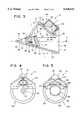
- FIG. 4is a front elevational view of the probing retroreflector shown in FIG. 3;
- FIG. 5is a rear elevational view of the probing retroreflector shown in FIG. 3;
- FIG. 6is an optical schematic, not to scale, of the probing retroreflector in accordance with the invention in connection with an exemplary tracking laser interferometer and target;
- FIG. 7is a side elevational diagrammatic view, not to scale, of a modified probing retroreflector in accordance with the invention in which the sensor comprises a glass slide and a reticle;
- FIG. 8is a front elevational view of the target shown in FIG. 7;
- FIG. 9is a rear elevational view of the glass slide and reticle shown in FIG. 7;
- FIG. 10is a side elevational diagrammatic view, not to scale, of a further modified probing retroreflector in accordance with the invention in which the sensor is of the non-contact type and comprises a series of lenses, a glass slide and a reticle.
- the probing retroreflector 10 in accordance with the inventionis intended to locate and follow the contour of a target surface such as surface 12 having a rectangular cross section, and to determine its three-dimensional x, y and z spatial coordinates and thus contour from a reference location using, for example, a tracking laser interferometer 14 rigidly positioned at the reference location 15 as seen in FIGS. 1 and 2.
- the tracking laser interferometer 14basically comprises a laser 16 capable of generating a laser beam 18 and first and second beam steering assemblies 20 and 22 used to track the probing retroreflector 10 as it is moved relative to the target surface 12.
- the steering assemblies 20 and 22pivot, respectively, about substantially perpendicular and intersecting X and Y axes and direct the laser beam 18 along an R axis, which is perpendicular to the X axis and intersects the X and Y axes.
- the laser beamis intercepted by the probing retroreflector 10, which, for example, engages the target surface 12 and which returns the laser beam to a position sensitive photodetector 24 via the steering assemblies.
- the photo detectorgenerates an error signal based on a lateral displacement of the laser beam and representative of the probing retroreflector's movement relative to the X and Y axes, and this signal is transmitted to two motors 26 and 28 which pivot the steering assemblies about the X and Y axes to reduce the error to zero.
- the tracking laser interferometer 14also includes an interferometer 30 which utilizes the laser beam 18 to determine the distance of the object from the reference location. The three-dimensional x, y and z spatial coordinates of the target surface can then be determined using that distance plus, for example, angle encoders coupled to the pivot axes X and Y for the first and second beam steering assemblies 20 and 22, i.e., using the three-dimensional polar coordinates generated thereby.
- three tracking laser interferometerscan be used to continually provide three distance measurements from the fixed reference location or position 15 and thereby provide a three-dimensional coordinate for all points on the target surface via trilateration.
- Examples of two tracking laser interferometersare disclosed in U.S. Pat. No. 4,621,926 to Merry et al and U.S. Pat. No. 4,790,651 to Brown et al, the disclosures of which are hereby incorporated herein by reference.
- the measuring meanscould use any other distance measuring technology such as laser radar or electronic distance measurement, all of which employ light and function by comparing the phase of the returning light with the outgoing light to determine range.
- the measuring meanswould optimally be a three-dimensional type, determining all three degrees of spatial freedom of the probing retroreflector, but there would be applications where only the range or angular orientation is used.
- the systemcan be used to determine at least one of the three spatial or polar coordinates of a target as desired.
- the measuring meanswould track the retroreflector, but there could also be applications where a beam would scan an area to find the retroreflector and then measure it without actually tracking.
- the probing retroreflector 10comprising a rigid support 32, an internal retroreflector assembly 34 rigidly coupled to the support, a planar reflector assembly 36 rigidly coupled to the support inside the support, and a sensor or probe 38 at one end of the support.
- Support 32has a substantially conical main body 40 and a central axis A as seen in FIG. 3.
- the outer conical shapeis not a necessary feature of the invention, but is merely convenient. Any rigid structure that attaches to the retroreflector assembly, the planar reflector assembly and the sensor, and holds them in good dimensional stability while not interfering with the beam, i.e., provides an open conical volume for the beam, is acceptable.
- the main bodypreferably provides a suitable place for the user to hold it without interfering with the light beam.
- the inside of the main body 10is of a dark, non-reflective color such as black.
- the main bodyis formed of rigid material such as metal, and has a first end 42 and a second end 44.
- the first end 42has a through bore 46 therein for mounting the planar reflector assembly 36 and the second end 44 is open for the transmission of the light beams into and out of the main body.
- the main body 40has a hollow, substantially frustoconical cavity 48 therein communicating with the second open end 44 and a slot 50 at the top for light beam communication with the retroreflector assembly 34 as seen in FIG. 3.
- a blind bore 52is also provided in the main body to help support the retroreflector assembly 34 thereon as discussed below.
- the retroreflector assembly 34basically comprises a corner cube 54 comprised of three planar, mutually orthogonal surfaces 56, 58 and 60 as seen in FIG. 3.
- the corner cube 54has a central axis B which intersects with the planar reflector assembly 36 and axis A, and has a center point C.
- the corner cube 54is advantageously coupled to and supported by a cylindrical can 62 which has a rim 64 which is rigidly coupled, such as by screws, to a rigid planar support plate 66 which is in turn rigidly coupled via screws 68, seen in FIG. 5, to the main body 40 of the support 32.
- the support plate 66has a central opening 70 through which the light beam can pass between the retroreflector assembly 34 and the planar reflector assembly 36 as seen in FIGS. 1-5.
- a rigid support rod 72is supported in the blind bore 52 in the main body and rigidly coupled thereto via any suitable means, such as screws, adhesive or welds, and is also rigidly coupled to the support plate 66 via any suitable means, such as screws, adhesive, or welds. This rigidly couples the retroreflector assembly 34 to the main body in the desired position as shown in FIGS. 1-5 above slot 50.
- the retroreflector assemblycould also be a cat's eye type retrosphere whose center point lies on the common center of two hemispheres, or any catadioptric system of lenses and mirrors made to function as a retroreflector and having a unique or predictable center point.
- the planar reflector assembly 36basically comprises a front surface reflector or mirror 74 having a support member 76 rigidly coupled thereto via, for example, adhesive, and rigidly coupled to the main body via, for example, a screw 78 received in bore 46 therein.
- plane Dcontains the planar front surface of the reflector 74 and intersects at a common point with central axis A of the support and central axis B of the corner cube 54.
- Front surface reflector 74is used to reflect the incoming laser beam 18 on the R axis from the laser 16 towards the corner cube, and receives the laser beam reflected back from the corner cube and returns and reflects the laser beam back towards the source of the laser beam at the laser 16 and reference position 15.
- the front surface reflector 74could also be a pentaprism, right angle prism, or any other reflector designed to fold, i.e., reflect, the beam path.
- the reflectorcan be arranged such that the light beam is reflected about 45° as shown.
- the angle of plane D containing the front surface reflector 74is about 60° with the central axis B of the corner cube 54, although that angle could be any angle greater than zero and less than 180°.
- the sensor 38 seen in FIGS. 1-4is rigidly located at the first end 42 of the main body 40 and is used to sense the location of the target surface by, for example, contacting or touching the surface.
- the sensor 34comprises an elongated, slender probe 80 having a substantially spherical distal end 82, with the distal end riding across and following the contour of the target surface.
- the diameter of the spherical endcan be about 1/32" or 1/8", or larger or smaller as necessary.
- the probe 80can be rigidly coupled to the main body via integral threaded member 84 threadedly received in a suitable threaded bore in the main body. It could also be secured by a slip fit and a set screw.
- the probeis shown as a small spherical ball, it can be a sharp pointed member or a segment of a sphere. It could be any shape designed to be placed on contact with a surface to be measured and keep a predictable offset distance between the target surface and center point C. That center point C is the virtual, i.e., representational, location of the center point of the sensor as viewed through the planar reflector assembly 36 and with respect to the laser light beam. If the probe tip is a sharp point, then the predictable offset would be substantially zero.
- the center of the sensor and the center point Care substantially equidistant from and on opposite sides of plane D containing the planar reflector assembly. Likewise, the center of the sensor and the retroreflector assembly center point C are on a line E which is substantially perpendicular to plane D as seen in FIG. 3.
- the distance between the intersection of central axis A and central axis B on the reflector assembly 36 with both the center point of the sensor 38 and the center point C of the corner cubeare substantially equal.
- the sensor 38is normally rigidly attached to the retroreflector 10; however, there exist touch probes which send an electrical signal to another device when the probe tip is touched. This type of probe could also be used with the present invention, but would not be perfectly rigid since it would move slightly when touched.
- the probe tipcould also be replaced with a contact or non-contact measurement probe such as a laser probe, dial indicator, electronic indicator, or LVDT.
- the tracking laser interferometer 14is illustrated in more detail and in conjunction with the probing retroreflector 10 in accordance with the invention and the target surface 12.
- the tracking laser interferometer 14is fully disclosed in U.S. Pat. No. 4,790,651 to Brown et al; however, for completeness and ease of understanding, portions of the tracking laser interferometer as seen in FIG. 6 are described in further detail below.
- the tracking laser interferometer 14basically comprises the laser 16 capable of generating a coherent laser beam 18, and first and second beam steering assemblies 20 and 22 which are capable of tracking the probing retroreflector 10 as it is moved along the target surface 12.
- the first beam steering assembly 20includes two prisms 90 and 92 which redirect the laser beam 18 through three 90° reflections from an initial direction parallel to the Y axis and towards the X axis to an intermediate direction along the X axis and towards the Y axis.
- the second beam steering assembly 22includes a third prism 94 which redirects the laser beam through one 90° reflection from the intermediate direction along the X axis to one coincident with the R axis where it is intersected by the probing retroreflector 10 and returned to the prism 94 and then the photodetector 24.
- the tracking laser interferometer 14includes first and second motors 26 and 28 to pivot respectively the first and second beam steering assemblies, the detection assembly comprising the photodetector 24, and a control system 96 for receiving an error signal from the photodetector and providing the necessary signals for actuating motors 26 and 28.
- An output line 98extends between the photodetector 24 and the control system 96.
- the first beam steering assembly 20also includes a first support 100, an upper tubular shaft 102, and a lower tubular shaft 104, all of which pivot about the Y axis through about plus or minus 90°.
- the first support 100 and prisms 90 and 92can pivot about the Y axis in a scanning action relative to shafts 102 and 104, which are coaxial with each other and the Y axis.
- the first prism 90has a quarter waveplate 106 on its bottom for use with a polarized laser beam.
- rigidly coupled to the top of prism 92is an upper coated mirrored prism 107 which combines with prism 92 to form a beam splitter, allowing about 15% light leakage therethrough towards photodetector 24. Facing the third prism 94 and rigidly coupled to the second prism is a quarter waveplate 109.
- the second beam steering assemblycomprises a second, S-shaped support 108, a left side shaft 110, and a right side tubular shaft 112, as well as the third front surface prism 94, all of which pivot about the X axis and are supported by the first support 100.
- the third prism 94is located so that its 45° reflective surface is at the intersection of the X and Y axes which defines point S in space about which pivoting of the supports takes place.
- the alignment of these axes as defined by shafts 102 and 104 and shafts 110 and 112is as accurate as the best machining tolerances will allow.
- Shafts 110 and 112pivotally couple support 108 and prism 94 to the first support 100 for pivotal scanning movement about the X axis.
- the position sensitive photodetector 24is rigidly supported inside the right side shaft 112 and is aligned with the X axis. Adjacent prism 92 and on the inner end of shaft 112 is a plano-convex lens 114 for focusing the laser beam on the photodetector 24.
- the photodetectorcomprises a detection assembly and is advantageously in the form of a quadrant detector, also known as a quad cell. Extending from the photodetector is the output line 98 which provides the error signal to the control system 96.
- the control system 96has a first output line 116 connected with the first motor 26 and a second output line 118 connected to the second motor 28.
- the control systemis a conventional device that will take the error signal from the photodetector 24 and energize the first and second motors to rotate in the appropriate directions and for the appropriate amount of time in order to reduce the error signal to zero.
- This control systembasically includes a digital computer with the necessary logic.
- the interferometer 30is an optical distance measuring machine and comprises a receiver, or fringe counter, 120, a beam splitter 122, a quarter waveplate 124, and a corner cube 126. These elements forming the interferometer are rigidly coupled in a position where the beam splitter 122 intercepts the laser beam 18 and splits it into first and second parts. The first part is directed towards the target.
- the receiver 120intercepts the second part of the laser beam as reflected via the corner cube 126 from the beam steering assemblies. This provides a reference beam for the receiver, which ultimately intercepts the first part of the beam reflected from the retroreflector assembly 10 and determines a distance measurement of the target from the reference position.
- a beam guiding 45° rear surface prism 128is rigidly located in alignment with the Y axis and below a quarter waveplate 130.
- the retroreflector 10receives the laser beam 18 as it is reflected from the prism 94 as seen in FIG. 6 along the R axis and in turn reflects the laser beam back to prism 94.
- This R axisis perpendicular to the X axis, intersects with the X and Y axes at point S, and varies angularly relative to the Y axis as the retroreflector moves along surface 12.
- the main purpose of the probing retroreflector 10is to locate and move along the contour of target surface 12, while the tracking laser interferometer 14 continuously determines three-dimensional coordinates for the series of points comprising the contact of the sensor 38 on the retroreflector with the target surface. By generating these coordinates, the system can determine the overall contour of the surface, or the location of any point on the surface.
- the tracking laser interferometer 14is actuated and acquires the probing retroreflector 10, which is in contact with the surface 12, the probing retroreflector is moved along the surface 12 by hand or machine.
- a laser light beam 18is directed generally towards the target surface 12 from a source of the laser beam located at laser 16 at the fixed reference position 15 as seen in FIGS. 1 and 2.
- the laser beamis aimed at and is reflected generally away from the surface by planar reflector 74 and towards, in the form of an input beam, the center point C of the corner cube 54 in space, which point represents the virtual location of the center point of the spherical ball 82 at the distal end of the sensor 38 in contact with the target surface 12.
- the laser lightis then incident on the corner cube 54 and is retroreflected, in the form of an output beam, by the corner cube in the opposite direction and in a substantially parallel manner as indicated in FIGS. 1 and 2.
- the light beamis then reflected generally away from the target surface and generally towards the source and reference position via planar reflector 74.
- the probing retroreflectoris periodically moved by hand or machine along the target surface, thereby moving the point in space relative to the target surface. That point in space has its distance from the reference position periodically measured by the tracking laser interferometer 14. By determining the positions of the series of points of contact of the sensor on the target surface, the actual contour of the surface can be determined.
- the radial offset between the outer surface of the sensor and its center pointcan be compensated for via software used in the control system 96 to maintain a high degree of accuracy.
- FIGS. 7-9An alternative embodiment of the invention is shown in FIGS. 7-9 in which a modified retroreflector 10' uses as the sensor a transparent glass slide 140 rigidly coupled to the main body and carrying a reticle 142 thereon.
- the reticle 142senses the location of the target 144 on the overall surface 146 by being physically aligned with the target.
- This type of "bomb sight” sensoris advantageously used to align the retroreflector 10' with very small targets.
- the remaining parts of the retroreflector 10'are the same as those described above regarding retroreflector 10, and like reference numerals are used in FIGS. 7-9 with the addition of a prime.
- the reticle 142 as seen in FIG. 9is a simple pair of perpendicular cross hairs enclosed in a circle, but it could be any other system of lines, dots, cross hairs, or wires in the focus of the lens 150.
- the retroreflector 10' of FIGS. 7-9is manipulated by the operator so that the glass slide 140 is placed on the surface 146 and is moved until the reticle 142 is aligned with the target 144. Such alignment can be obtained and viewed by the operator by looking through the magnifying lens 150 and observing the reticle 142 and the target 144. The retroreflector is then operated as necessary as discussed above regarding retroreflector 10 in FIGS. 1-6.
- FIG. 10Another alternative embodiment of the invention is shown in FIG. 10 in which a modified retroreflector 10" uses another bomb sight target sensor for sensing the target without actually physically contacting the target.
- the sensorcomprises a focusing lens 160, a glass slide 162, a reticle 164 on the slide, and a magnifying lens 166, all rigidly coupled to the retroreflector 10" and optically aligned.
- Reticle 164can be the same as reticle 142 shown in FIGS. 7-9. Reticle 164 is also advantageously used to sense the location of very small targets.
- the remaining parts of the retroreflector 10"are the same as those described above regarding retroreflector 10, and like reference numerals are used in FIG. 10 with the addition of a double prime.
- the retroreflector 10" of FIG. 10is manipulated by the operator so that the sensor 38" comprising lens 160, slide 162, reticle 164 and lens 166 are aligned with the target 144 and the image of the target 144 is in focus with the reticle 164, as determined by the operator viewing through lens 166.
- the retroreflectoris then operated as necessary as discussed above regarding retroreflector 10 in FIGS. 1-6.
- the main bodycan have a substantially U-shaped recess to receive the target therein.
- the planar reflector and corner cubewould be on one side of the U-shaped recess and the sensor would be on the other side.
- the laser beamshould be directed at the target surface at an angle of not smaller than about 10° and not greater than about 50° with a main body of minimum size. If a bomb sight visual sensor is used, this angle range can be about 5° to about 40°.
- a remote push button or other switch control for the laser and trackercan be located on the retroreflector assembly and communicate with the tracker via wire, radio, infrared, or similar methods.
- any additional desired illumination devices and beam splitterscan be used to aid in viewing of the target and aiming of the retroreflector assembly.
Landscapes
- Physics & Mathematics (AREA)
- Electromagnetism (AREA)
- Engineering & Computer Science (AREA)
- General Physics & Mathematics (AREA)
- Computer Networks & Wireless Communication (AREA)
- Radar, Positioning & Navigation (AREA)
- Remote Sensing (AREA)
- Length Measuring Devices By Optical Means (AREA)
Abstract
Description
Claims (24)
Priority Applications (1)
| Application Number | Priority Date | Filing Date | Title |
|---|---|---|---|
| US08/248,150US5530549A (en) | 1994-05-24 | 1994-05-24 | Probing retroreflector and methods of measuring surfaces therewith |
Applications Claiming Priority (1)
| Application Number | Priority Date | Filing Date | Title |
|---|---|---|---|
| US08/248,150US5530549A (en) | 1994-05-24 | 1994-05-24 | Probing retroreflector and methods of measuring surfaces therewith |
Publications (1)
| Publication Number | Publication Date |
|---|---|
| US5530549Atrue US5530549A (en) | 1996-06-25 |
Family
ID=22937899
Family Applications (1)
| Application Number | Title | Priority Date | Filing Date |
|---|---|---|---|
| US08/248,150Expired - LifetimeUS5530549A (en) | 1994-05-24 | 1994-05-24 | Probing retroreflector and methods of measuring surfaces therewith |
Country Status (1)
| Country | Link |
|---|---|
| US (1) | US5530549A (en) |
Cited By (32)
| Publication number | Priority date | Publication date | Assignee | Title |
|---|---|---|---|---|
| GB2311862A (en)* | 1996-04-05 | 1997-10-08 | Matsushita Electric Industrial Co Ltd | Profile measuring apparatus |
| US5861956A (en)* | 1997-05-27 | 1999-01-19 | Spatialmetrix Corporation | Retroreflector for use with tooling ball |
| EP0895096A3 (en)* | 1997-07-31 | 1999-09-15 | The Boeing Company | Portable laser digitizing system for large parts |
| US6094287A (en)* | 1998-12-03 | 2000-07-25 | Eastman Kodak Company | Wobble correcting monogon scanner for a laser imaging system |
| US6299122B1 (en) | 1999-09-28 | 2001-10-09 | Northrup Grumman Corporation | Spherically mounted retroreflector edge adapter |
| US20030227616A1 (en)* | 2002-02-22 | 2003-12-11 | Bridges Robert E. | Spherically mounted light source with angle measuring device, tracking system, and method for determining coordinates |
| US20040160594A1 (en)* | 2003-02-14 | 2004-08-19 | Metronor Asa | Measurement of spatial coordinates |
| US20050002044A1 (en)* | 2003-04-29 | 2005-01-06 | Pruftechnik Dieter Busch Ag | Method for determination of the level of two or more measurement points, and an arrangement for this purpose |
| US6892160B2 (en) | 2000-04-06 | 2005-05-10 | Bae Systems Plc | Assembly method |
| US20050157410A1 (en)* | 2004-01-15 | 2005-07-21 | Associated Universities, Inc. | Multidirectional retroflector |
| US20070216904A1 (en)* | 2001-06-07 | 2007-09-20 | Facet Technology Corporation | System for automated determination of retroreflectivity of road signs and other reflective objects |
| US20070297805A1 (en)* | 2006-06-23 | 2007-12-27 | William Rabinovich | Optical communication system with cats-eye modulating retro-reflector (mrr) assembly, the cats-eye mrr assembly thereof, and the method of optical communication |
| US20080043252A1 (en)* | 2006-06-27 | 2008-02-21 | Parlour Noel S | Internal and external measuring device |
| US7372581B2 (en) | 2005-04-11 | 2008-05-13 | Faro Technologies, Inc. | Three-dimensional coordinate measuring device |
| US20090252376A1 (en)* | 2000-08-12 | 2009-10-08 | Retterath Jamie E | System for Road Sign Sheeting Classification |
| US20090323121A1 (en)* | 2005-09-09 | 2009-12-31 | Robert Jan Valkenburg | A 3D Scene Scanner and a Position and Orientation System |
| US20100095542A1 (en)* | 2008-10-16 | 2010-04-22 | Romer, Inc. | Articulating measuring arm with laser scanner |
| DE102009019871A1 (en) | 2009-05-06 | 2010-11-25 | Konrad Maierhofer | Auxiliary device for the fine adjustment of a laser beam to a predefinable target point |
| US7941269B2 (en) | 2005-05-06 | 2011-05-10 | Rialcardo Tice B.V. Llc | Network-based navigation system having virtual drive-thru advertisements integrated with actual imagery from along a physical route |
| US20110107614A1 (en)* | 2009-11-06 | 2011-05-12 | Hexagon Metrology Ab | Enhanced position detection for a cmm |
| US20110176145A1 (en)* | 2010-01-18 | 2011-07-21 | Faro Technologies, Inc | Sphere bar probe |
| US8150216B2 (en) | 2004-05-05 | 2012-04-03 | Google Inc. | Methods and apparatus for automated true object-based image analysis and retrieval |
| US20120113433A1 (en)* | 2008-11-04 | 2012-05-10 | Sergiy Pryadkin | Optical method for precise three-dimensional position measurement |
| EP3232223A1 (en)* | 2016-04-15 | 2017-10-18 | Airbus DS GmbH | Reflective device for use in an optical measuring system |
| US9857160B1 (en) | 2013-09-24 | 2018-01-02 | TVS Holdings, LLC | Multi-mode frequency sweeping interferometer and method of using same |
| US9976947B1 (en) | 2014-11-24 | 2018-05-22 | TVS Holdings, LLC | Position measurement device |
| US9983298B2 (en) | 2015-02-05 | 2018-05-29 | Associated Universities, LLC | Fiber optic based laser range finder |
| US10036627B2 (en) | 2014-09-19 | 2018-07-31 | Hexagon Metrology, Inc. | Multi-mode portable coordinate measuring machine |
| US10429661B2 (en) | 2017-08-08 | 2019-10-01 | Sensors Unlimited, Inc. | Retroreflector detectors |
| US10679367B2 (en)* | 2018-08-13 | 2020-06-09 | Hand Held Products, Inc. | Methods, systems, and apparatuses for computing dimensions of an object using angular estimates |
| US10769458B2 (en) | 2008-02-12 | 2020-09-08 | DBI/CIDAUT Technologies, LLC | Determination procedure of the luminance of traffic signs and device for its embodiment |
| WO2024116134A1 (en)* | 2022-12-02 | 2024-06-06 | Cape Peninsula University Of Technology | A coordinate movement machine |
Citations (11)
| Publication number | Priority date | Publication date | Assignee | Title |
|---|---|---|---|---|
| US2589618A (en)* | 1944-05-11 | 1952-03-18 | Learned Charles Horace | Mirror signaling device |
| US4457625A (en)* | 1981-07-13 | 1984-07-03 | Itek Corporation | Self calibrating contour measuring system using fringe counting interferometers |
| US4483618A (en)* | 1982-05-24 | 1984-11-20 | Hamar M R | Laser measurement system, virtual detector probe and carriage yaw compensator |
| US4621926A (en)* | 1985-04-30 | 1986-11-11 | Lasercon Corporation | Interferometer system for controlling non-rectilinear movement of an object |
| US4714339A (en)* | 1986-02-28 | 1987-12-22 | The United States Of America As Represented By The Secretary Of Commerce | Three and five axis laser tracking systems |
| US4790651A (en)* | 1987-09-30 | 1988-12-13 | Chesapeake Laser Systems, Inc. | Tracking laser interferometer |
| US4886353A (en)* | 1987-03-17 | 1989-12-12 | D.E.A. Digital Electronic Automation S.P.A. | Measuring device employing laser interferometry |
| US4926559A (en)* | 1988-03-15 | 1990-05-22 | Rheinmetall Gmbh | Measuring device for determining the position of workpiece faces |
| US4942671A (en)* | 1988-07-20 | 1990-07-24 | Carl-Zeiss-Stiftung | Probe head mount for a deflectable probe or the like |
| US4972597A (en)* | 1988-12-15 | 1990-11-27 | Governor of Toyama Prefecture, Yutaka Nakaoki | Three-dimensional displacement gage |
| US5174039A (en)* | 1990-08-17 | 1992-12-29 | Kabushiki Kaisha Toshiba | Displacement-measuring apparatus, and static-pressure bearing device for use in the displacement-measuring apparatus |
- 1994
- 1994-05-24USUS08/248,150patent/US5530549A/ennot_activeExpired - Lifetime
Patent Citations (13)
| Publication number | Priority date | Publication date | Assignee | Title |
|---|---|---|---|---|
| US2589618A (en)* | 1944-05-11 | 1952-03-18 | Learned Charles Horace | Mirror signaling device |
| US4457625A (en)* | 1981-07-13 | 1984-07-03 | Itek Corporation | Self calibrating contour measuring system using fringe counting interferometers |
| US4483618A (en)* | 1982-05-24 | 1984-11-20 | Hamar M R | Laser measurement system, virtual detector probe and carriage yaw compensator |
| US4621926A (en)* | 1985-04-30 | 1986-11-11 | Lasercon Corporation | Interferometer system for controlling non-rectilinear movement of an object |
| US4714339B1 (en)* | 1986-02-28 | 1997-03-18 | Us Army | Three and five axis laser tracking systems |
| US4714339A (en)* | 1986-02-28 | 1987-12-22 | The United States Of America As Represented By The Secretary Of Commerce | Three and five axis laser tracking systems |
| US4714339B2 (en)* | 1986-02-28 | 2000-05-23 | Us Commerce | Three and five axis laser tracking systems |
| US4886353A (en)* | 1987-03-17 | 1989-12-12 | D.E.A. Digital Electronic Automation S.P.A. | Measuring device employing laser interferometry |
| US4790651A (en)* | 1987-09-30 | 1988-12-13 | Chesapeake Laser Systems, Inc. | Tracking laser interferometer |
| US4926559A (en)* | 1988-03-15 | 1990-05-22 | Rheinmetall Gmbh | Measuring device for determining the position of workpiece faces |
| US4942671A (en)* | 1988-07-20 | 1990-07-24 | Carl-Zeiss-Stiftung | Probe head mount for a deflectable probe or the like |
| US4972597A (en)* | 1988-12-15 | 1990-11-27 | Governor of Toyama Prefecture, Yutaka Nakaoki | Three-dimensional displacement gage |
| US5174039A (en)* | 1990-08-17 | 1992-12-29 | Kabushiki Kaisha Toshiba | Displacement-measuring apparatus, and static-pressure bearing device for use in the displacement-measuring apparatus |
Cited By (71)
| Publication number | Priority date | Publication date | Assignee | Title |
|---|---|---|---|---|
| US5917181A (en)* | 1996-04-05 | 1999-06-29 | Marsushita Electric Industrial, Co., Ltd. | Profile measuring apparatus |
| GB2311862B (en)* | 1996-04-05 | 2000-09-06 | Matsushita Electric Industrial Co Ltd | Profile measuring apparatus |
| GB2311862A (en)* | 1996-04-05 | 1997-10-08 | Matsushita Electric Industrial Co Ltd | Profile measuring apparatus |
| US5861956A (en)* | 1997-05-27 | 1999-01-19 | Spatialmetrix Corporation | Retroreflector for use with tooling ball |
| EP0895096A3 (en)* | 1997-07-31 | 1999-09-15 | The Boeing Company | Portable laser digitizing system for large parts |
| US6094287A (en)* | 1998-12-03 | 2000-07-25 | Eastman Kodak Company | Wobble correcting monogon scanner for a laser imaging system |
| US6299122B1 (en) | 1999-09-28 | 2001-10-09 | Northrup Grumman Corporation | Spherically mounted retroreflector edge adapter |
| US6892160B2 (en) | 2000-04-06 | 2005-05-10 | Bae Systems Plc | Assembly method |
| US9335255B2 (en) | 2000-08-12 | 2016-05-10 | Facet Technology Corp. | System and assessment of reflective objects along a roadway |
| US9989456B2 (en) | 2000-08-12 | 2018-06-05 | Facet Technology Corp. | System for the determination of retroreflectivity of road signs and other reflective objects |
| US7995796B2 (en) | 2000-08-12 | 2011-08-09 | Facet Technology Corp. | System for road sign sheeting classification |
| US9671328B2 (en) | 2000-08-12 | 2017-06-06 | Facet Technology Corp. | System and assessment of reflective objects along a roadway |
| US8860944B2 (en) | 2000-08-12 | 2014-10-14 | Facet Technology Corp. | System and assessment of reflective objects along a roadway |
| US20090252376A1 (en)* | 2000-08-12 | 2009-10-08 | Retterath Jamie E | System for Road Sign Sheeting Classification |
| US9989457B2 (en) | 2000-08-12 | 2018-06-05 | Mandli Communications, Inc. | System and assessment of reflective objects along a roadway |
| US8660311B2 (en) | 2000-08-12 | 2014-02-25 | Facet Technology Corp. | System for assessment reflective objects along a roadway |
| US7411681B2 (en)* | 2001-06-07 | 2008-08-12 | Facet Technology Corporation | System for automated determination of retroreflectivity of road signs and other reflective objects |
| US20070216904A1 (en)* | 2001-06-07 | 2007-09-20 | Facet Technology Corporation | System for automated determination of retroreflectivity of road signs and other reflective objects |
| US20030227616A1 (en)* | 2002-02-22 | 2003-12-11 | Bridges Robert E. | Spherically mounted light source with angle measuring device, tracking system, and method for determining coordinates |
| US7248374B2 (en)* | 2002-02-22 | 2007-07-24 | Faro Laser Trackers Llc | Spherically mounted light source with angle measuring device, tracking system, and method for determining coordinates |
| US7145647B2 (en) | 2003-02-14 | 2006-12-05 | Metronor Asa | Measurement of spatial coordinates |
| US20040160594A1 (en)* | 2003-02-14 | 2004-08-19 | Metronor Asa | Measurement of spatial coordinates |
| US20050002044A1 (en)* | 2003-04-29 | 2005-01-06 | Pruftechnik Dieter Busch Ag | Method for determination of the level of two or more measurement points, and an arrangement for this purpose |
| US7212294B2 (en)* | 2003-04-29 | 2007-05-01 | Prüftechnik Dieter Busch AG | Method for determination of the level of two or more measurement points, and an arrangement for this purpose |
| US7101053B2 (en)* | 2004-01-15 | 2006-09-05 | Associated Universities, Inc. | Multidirectional retroreflectors |
| US20050157410A1 (en)* | 2004-01-15 | 2005-07-21 | Associated Universities, Inc. | Multidirectional retroflector |
| USRE41877E1 (en)* | 2004-01-15 | 2010-10-26 | Associated Universities, Inc. | Multidirectional retroreflectors |
| US8908997B2 (en) | 2004-05-05 | 2014-12-09 | Google Inc. | Methods and apparatus for automated true object-based image analysis and retrieval |
| US8908996B2 (en) | 2004-05-05 | 2014-12-09 | Google Inc. | Methods and apparatus for automated true object-based image analysis and retrieval |
| US8903199B2 (en) | 2004-05-05 | 2014-12-02 | Google Inc. | Methods and apparatus for automated true object-based image analysis and retrieval |
| US9424277B2 (en) | 2004-05-05 | 2016-08-23 | Google Inc. | Methods and apparatus for automated true object-based image analysis and retrieval |
| US8150216B2 (en) | 2004-05-05 | 2012-04-03 | Google Inc. | Methods and apparatus for automated true object-based image analysis and retrieval |
| US7372581B2 (en) | 2005-04-11 | 2008-05-13 | Faro Technologies, Inc. | Three-dimensional coordinate measuring device |
| US7941269B2 (en) | 2005-05-06 | 2011-05-10 | Rialcardo Tice B.V. Llc | Network-based navigation system having virtual drive-thru advertisements integrated with actual imagery from along a physical route |
| US8406992B2 (en) | 2005-05-06 | 2013-03-26 | Rialcardo Tice B.V. Llc | Network-based navigation system having virtual drive-thru advertisements integrated with actual imagery from along a physical route |
| US20090323121A1 (en)* | 2005-09-09 | 2009-12-31 | Robert Jan Valkenburg | A 3D Scene Scanner and a Position and Orientation System |
| US8625854B2 (en) | 2005-09-09 | 2014-01-07 | Industrial Research Limited | 3D scene scanner and a position and orientation system |
| US20070297805A1 (en)* | 2006-06-23 | 2007-12-27 | William Rabinovich | Optical communication system with cats-eye modulating retro-reflector (mrr) assembly, the cats-eye mrr assembly thereof, and the method of optical communication |
| US20080043252A1 (en)* | 2006-06-27 | 2008-02-21 | Parlour Noel S | Internal and external measuring device |
| US7440120B2 (en) | 2006-06-27 | 2008-10-21 | Barbara E. Parlour | Internal and external measuring device |
| US10769458B2 (en) | 2008-02-12 | 2020-09-08 | DBI/CIDAUT Technologies, LLC | Determination procedure of the luminance of traffic signs and device for its embodiment |
| US20110192043A1 (en)* | 2008-10-16 | 2011-08-11 | Hexagon Metrology, Inc. | Articulating measuring arm with laser scanner |
| US9618330B2 (en) | 2008-10-16 | 2017-04-11 | Hexagon Metrology, Inc. | Articulating measuring arm with laser scanner |
| US11029142B2 (en) | 2008-10-16 | 2021-06-08 | Hexagon Metrology, Inc. | Articulating measuring arm with laser scanner |
| US10337853B2 (en) | 2008-10-16 | 2019-07-02 | Hexagon Metrology, Inc. | Articulating measuring arm with laser scanner |
| US8438747B2 (en) | 2008-10-16 | 2013-05-14 | Hexagon Metrology, Inc. | Articulating measuring arm with laser scanner |
| US8176646B2 (en) | 2008-10-16 | 2012-05-15 | Hexagon Metrology, Inc. | Articulating measuring arm with laser scanner |
| US20100095542A1 (en)* | 2008-10-16 | 2010-04-22 | Romer, Inc. | Articulating measuring arm with laser scanner |
| US7908757B2 (en) | 2008-10-16 | 2011-03-22 | Hexagon Metrology, Inc. | Articulating measuring arm with laser scanner |
| US8955229B2 (en) | 2008-10-16 | 2015-02-17 | Hexagon Metrology, Inc. | Articulating measuring arm with optical scanner |
| US8330963B2 (en)* | 2008-11-04 | 2012-12-11 | Sergiy Pryadkin | Optical method for precise three-dimensional position measurement |
| US20120113433A1 (en)* | 2008-11-04 | 2012-05-10 | Sergiy Pryadkin | Optical method for precise three-dimensional position measurement |
| DE102009019871A1 (en) | 2009-05-06 | 2010-11-25 | Konrad Maierhofer | Auxiliary device for the fine adjustment of a laser beam to a predefinable target point |
| DE102009019871B4 (en)* | 2009-05-06 | 2011-02-03 | Konrad Maierhofer | Auxiliary device for the fine adjustment of a laser beam to a predefinable target point |
| US8327555B2 (en) | 2009-11-06 | 2012-12-11 | Hexagon Metrology Ab | Enhanced position detection for a CMM |
| US20110107614A1 (en)* | 2009-11-06 | 2011-05-12 | Hexagon Metrology Ab | Enhanced position detection for a cmm |
| US8099877B2 (en) | 2009-11-06 | 2012-01-24 | Hexagon Metrology Ab | Enhanced position detection for a CMM |
| US20110176145A1 (en)* | 2010-01-18 | 2011-07-21 | Faro Technologies, Inc | Sphere bar probe |
| US8773667B2 (en) | 2010-01-18 | 2014-07-08 | Faro Technologies, Inc. | Sphere bar probe |
| US9857160B1 (en) | 2013-09-24 | 2018-01-02 | TVS Holdings, LLC | Multi-mode frequency sweeping interferometer and method of using same |
| US9857159B1 (en) | 2013-09-24 | 2018-01-02 | TVS Holdings, LLC | Velocity compensated frequency sweeping interferometer and method of using same |
| US10036627B2 (en) | 2014-09-19 | 2018-07-31 | Hexagon Metrology, Inc. | Multi-mode portable coordinate measuring machine |
| US11215442B2 (en) | 2014-09-19 | 2022-01-04 | Hexagon Metrology, Inc. | Multi-mode portable coordinate measuring machine |
| US10663284B2 (en) | 2014-09-19 | 2020-05-26 | Hexagon Metrology, Inc. | Multi-mode portable coordinate measuring machine |
| US9976947B1 (en) | 2014-11-24 | 2018-05-22 | TVS Holdings, LLC | Position measurement device |
| US9983298B2 (en) | 2015-02-05 | 2018-05-29 | Associated Universities, LLC | Fiber optic based laser range finder |
| EP3232223A1 (en)* | 2016-04-15 | 2017-10-18 | Airbus DS GmbH | Reflective device for use in an optical measuring system |
| US10317277B2 (en)* | 2016-04-15 | 2019-06-11 | Airbus Ds Gmbh | Reflective device for use in an optical measuring system |
| US10429661B2 (en) | 2017-08-08 | 2019-10-01 | Sensors Unlimited, Inc. | Retroreflector detectors |
| US10679367B2 (en)* | 2018-08-13 | 2020-06-09 | Hand Held Products, Inc. | Methods, systems, and apparatuses for computing dimensions of an object using angular estimates |
| WO2024116134A1 (en)* | 2022-12-02 | 2024-06-06 | Cape Peninsula University Of Technology | A coordinate movement machine |
Similar Documents
| Publication | Publication Date | Title |
|---|---|---|
| US5530549A (en) | Probing retroreflector and methods of measuring surfaces therewith | |
| EP1086354B1 (en) | Surface sensing device with optical sensor | |
| US10837756B2 (en) | Multi-dimensional measuring system with measuring instrument having 360° angular working range | |
| US10302413B2 (en) | Six degree-of-freedom laser tracker that cooperates with a remote sensor | |
| US9476695B2 (en) | Laser tracker that cooperates with a remote camera bar and coordinate measurement device | |
| US9989350B2 (en) | Laser-based coordinate measuring device and laser-based method for measuring coordinates | |
| EP1466136B1 (en) | Laser-based coordinate measuring device and laser-based method for measuring coordinates | |
| CN106595480B (en) | For measuring the laser measurement system and method for shaft six degree of freedom geometric error | |
| US6017125A (en) | Bar coded retroreflective target | |
| US5973788A (en) | System for point-by-point measuring of spatial coordinates | |
| US9453913B2 (en) | Target apparatus for three-dimensional measurement system | |
| US6667798B1 (en) | Method and device for determining spatial positions and orientations | |
| US4732472A (en) | Methods of, and systems for, determining the position of an object | |
| US6618132B1 (en) | Miniature laser tracker | |
| EP2793042A1 (en) | Positioning device comprising a light beam | |
| US20240125904A1 (en) | Sensor with curved reflector | |
| JP2025010643A (en) | Interferometer |
Legal Events
| Date | Code | Title | Description |
|---|---|---|---|
| AS | Assignment | Owner name:CHESAPEAKE LASER SYSTEMS, INC., PENNSYLVANIA Free format text:ASSIGNMENT OF ASSIGNORS INTEREST;ASSIGNOR:BROWN, LAWRENCE B.;REEL/FRAME:007010/0028 Effective date:19940521 | |
| AS | Assignment | Owner name:SPATIALMETRIX CORPORATION, PENNSYLVANIA Free format text:MERGER;ASSIGNOR:CHESAPEAKE LASER SYSTEMS, INC.;REEL/FRAME:007467/0150 Effective date:19950331 | |
| STCF | Information on status: patent grant | Free format text:PATENTED CASE | |
| AS | Assignment | Owner name:CORESTATES ENTERPRISE CAPITAL, INC., PENNSYLVANIA Free format text:SECURITY INTEREST;ASSIGNOR:SPATIALMETRIX CORPORATION;REEL/FRAME:008489/0768 Effective date:19970425 | |
| AS | Assignment | Owner name:PNC BANK, NATIONAL ASSOCIATION, PENNSYLVANIA Free format text:SECURITY AGREEMENT;ASSIGNOR:SPATIAL METRIX, INCORPORATED;REEL/FRAME:009445/0377 Effective date:19980128 | |
| FPAY | Fee payment | Year of fee payment:4 | |
| AS | Assignment | Owner name:FARO LASER TRACKERS, LLC, FLORIDA Free format text:CHANGE OF NAME;ASSIGNOR:FARO ACQUISITION, LLC;REEL/FRAME:013101/0322 Effective date:20020116 | |
| AS | Assignment | Owner name:FARO ACQUISITION, LLC, FLORIDA Free format text:MERGER;ASSIGNOR:SPATIALMETRIX CORPORATION;REEL/FRAME:013101/0065 Effective date:20020116 | |
| FPAY | Fee payment | Year of fee payment:8 | |
| FEPP | Fee payment procedure | Free format text:PAT HOLDER NO LONGER CLAIMS SMALL ENTITY STATUS, ENTITY STATUS SET TO UNDISCOUNTED (ORIGINAL EVENT CODE: STOL); ENTITY STATUS OF PATENT OWNER: LARGE ENTITY | |
| FPAY | Fee payment | Year of fee payment:12 | |
| AS | Assignment | Owner name:FARO TECHNOLOGIES, INC., FLORIDA Free format text:ASSIGNMENT OF ASSIGNORS INTEREST;ASSIGNOR:FARO LASER TRACKERS, LLC;REEL/FRAME:023668/0184 Effective date:20091129 | |
| AS | Assignment | Owner name:FARO TECHNOLOGIES, INC., FLORIDA Free format text:CORRECTIVE ASSIGNMENT TO CORRECT THE EXECUTION DATE SHOULD BE 11/20/2009 PREVIOUSLY RECORDED ON REEL 023668 FRAME 0184;ASSIGNOR:FARO LASER TRACKERS, LLC;REEL/FRAME:023741/0335 Effective date:20091120 |