US5529651A - Process for production of joined ceramic body - Google Patents
Process for production of joined ceramic bodyDownload PDFInfo
- Publication number
- US5529651A US5529651AUS08/341,074US34107494AUS5529651AUS 5529651 AUS5529651 AUS 5529651AUS 34107494 AUS34107494 AUS 34107494AUS 5529651 AUS5529651 AUS 5529651A
- Authority
- US
- United States
- Prior art keywords
- tubes
- plate
- plates
- ceramic
- tube
- Prior art date
- Legal status (The legal status is an assumption and is not a legal conclusion. Google has not performed a legal analysis and makes no representation as to the accuracy of the status listed.)
- Expired - Fee Related
Links
Images

Classifications
- C—CHEMISTRY; METALLURGY
- C04—CEMENTS; CONCRETE; ARTIFICIAL STONE; CERAMICS; REFRACTORIES
- C04B—LIME, MAGNESIA; SLAG; CEMENTS; COMPOSITIONS THEREOF, e.g. MORTARS, CONCRETE OR LIKE BUILDING MATERIALS; ARTIFICIAL STONE; CERAMICS; REFRACTORIES; TREATMENT OF NATURAL STONE
- C04B35/00—Shaped ceramic products characterised by their composition; Ceramics compositions; Processing powders of inorganic compounds preparatory to the manufacturing of ceramic products
- C04B35/622—Forming processes; Processing powders of inorganic compounds preparatory to the manufacturing of ceramic products
- C04B35/64—Burning or sintering processes
- C—CHEMISTRY; METALLURGY
- C04—CEMENTS; CONCRETE; ARTIFICIAL STONE; CERAMICS; REFRACTORIES
- C04B—LIME, MAGNESIA; SLAG; CEMENTS; COMPOSITIONS THEREOF, e.g. MORTARS, CONCRETE OR LIKE BUILDING MATERIALS; ARTIFICIAL STONE; CERAMICS; REFRACTORIES; TREATMENT OF NATURAL STONE
- C04B37/00—Joining burned ceramic articles with other burned ceramic articles or other articles by heating
- C04B37/001—Joining burned ceramic articles with other burned ceramic articles or other articles by heating directly with other burned ceramic articles
- C—CHEMISTRY; METALLURGY
- C04—CEMENTS; CONCRETE; ARTIFICIAL STONE; CERAMICS; REFRACTORIES
- C04B—LIME, MAGNESIA; SLAG; CEMENTS; COMPOSITIONS THEREOF, e.g. MORTARS, CONCRETE OR LIKE BUILDING MATERIALS; ARTIFICIAL STONE; CERAMICS; REFRACTORIES; TREATMENT OF NATURAL STONE
- C04B2235/00—Aspects relating to ceramic starting mixtures or sintered ceramic products
- C04B2235/65—Aspects relating to heat treatments of ceramic bodies such as green ceramics or pre-sintered ceramics, e.g. burning, sintering or melting processes
- C04B2235/656—Aspects relating to heat treatments of ceramic bodies such as green ceramics or pre-sintered ceramics, e.g. burning, sintering or melting processes characterised by specific heating conditions during heat treatment
- C04B2235/6567—Treatment time
- C—CHEMISTRY; METALLURGY
- C04—CEMENTS; CONCRETE; ARTIFICIAL STONE; CERAMICS; REFRACTORIES
- C04B—LIME, MAGNESIA; SLAG; CEMENTS; COMPOSITIONS THEREOF, e.g. MORTARS, CONCRETE OR LIKE BUILDING MATERIALS; ARTIFICIAL STONE; CERAMICS; REFRACTORIES; TREATMENT OF NATURAL STONE
- C04B2235/00—Aspects relating to ceramic starting mixtures or sintered ceramic products
- C04B2235/65—Aspects relating to heat treatments of ceramic bodies such as green ceramics or pre-sintered ceramics, e.g. burning, sintering or melting processes
- C04B2235/658—Atmosphere during thermal treatment
- C—CHEMISTRY; METALLURGY
- C04—CEMENTS; CONCRETE; ARTIFICIAL STONE; CERAMICS; REFRACTORIES
- C04B—LIME, MAGNESIA; SLAG; CEMENTS; COMPOSITIONS THEREOF, e.g. MORTARS, CONCRETE OR LIKE BUILDING MATERIALS; ARTIFICIAL STONE; CERAMICS; REFRACTORIES; TREATMENT OF NATURAL STONE
- C04B2237/00—Aspects relating to ceramic laminates or to joining of ceramic articles with other articles by heating
- C04B2237/30—Composition of layers of ceramic laminates or of ceramic or metallic articles to be joined by heating, e.g. Si substrates
- C04B2237/32—Ceramic
- C04B2237/36—Non-oxidic
- C04B2237/365—Silicon carbide
- C—CHEMISTRY; METALLURGY
- C04—CEMENTS; CONCRETE; ARTIFICIAL STONE; CERAMICS; REFRACTORIES
- C04B—LIME, MAGNESIA; SLAG; CEMENTS; COMPOSITIONS THEREOF, e.g. MORTARS, CONCRETE OR LIKE BUILDING MATERIALS; ARTIFICIAL STONE; CERAMICS; REFRACTORIES; TREATMENT OF NATURAL STONE
- C04B2237/00—Aspects relating to ceramic laminates or to joining of ceramic articles with other articles by heating
- C04B2237/30—Composition of layers of ceramic laminates or of ceramic or metallic articles to be joined by heating, e.g. Si substrates
- C04B2237/32—Ceramic
- C04B2237/36—Non-oxidic
- C04B2237/368—Silicon nitride
- C—CHEMISTRY; METALLURGY
- C04—CEMENTS; CONCRETE; ARTIFICIAL STONE; CERAMICS; REFRACTORIES
- C04B—LIME, MAGNESIA; SLAG; CEMENTS; COMPOSITIONS THEREOF, e.g. MORTARS, CONCRETE OR LIKE BUILDING MATERIALS; ARTIFICIAL STONE; CERAMICS; REFRACTORIES; TREATMENT OF NATURAL STONE
- C04B2237/00—Aspects relating to ceramic laminates or to joining of ceramic articles with other articles by heating
- C04B2237/50—Processing aspects relating to ceramic laminates or to the joining of ceramic articles with other articles by heating
- C04B2237/62—Forming laminates or joined articles comprising holes, channels or other types of openings
- C—CHEMISTRY; METALLURGY
- C04—CEMENTS; CONCRETE; ARTIFICIAL STONE; CERAMICS; REFRACTORIES
- C04B—LIME, MAGNESIA; SLAG; CEMENTS; COMPOSITIONS THEREOF, e.g. MORTARS, CONCRETE OR LIKE BUILDING MATERIALS; ARTIFICIAL STONE; CERAMICS; REFRACTORIES; TREATMENT OF NATURAL STONE
- C04B2237/00—Aspects relating to ceramic laminates or to joining of ceramic articles with other articles by heating
- C04B2237/50—Processing aspects relating to ceramic laminates or to the joining of ceramic articles with other articles by heating
- C04B2237/70—Forming laminates or joined articles comprising layers of a specific, unusual thickness
- C04B2237/704—Forming laminates or joined articles comprising layers of a specific, unusual thickness of one or more of the ceramic layers or articles
- C—CHEMISTRY; METALLURGY
- C04—CEMENTS; CONCRETE; ARTIFICIAL STONE; CERAMICS; REFRACTORIES
- C04B—LIME, MAGNESIA; SLAG; CEMENTS; COMPOSITIONS THEREOF, e.g. MORTARS, CONCRETE OR LIKE BUILDING MATERIALS; ARTIFICIAL STONE; CERAMICS; REFRACTORIES; TREATMENT OF NATURAL STONE
- C04B2237/00—Aspects relating to ceramic laminates or to joining of ceramic articles with other articles by heating
- C04B2237/50—Processing aspects relating to ceramic laminates or to the joining of ceramic articles with other articles by heating
- C04B2237/76—Forming laminates or joined articles comprising at least one member in the form other than a sheet or disc, e.g. two tubes or a tube and a sheet or disc
- C04B2237/765—Forming laminates or joined articles comprising at least one member in the form other than a sheet or disc, e.g. two tubes or a tube and a sheet or disc at least one member being a tube
- C—CHEMISTRY; METALLURGY
- C04—CEMENTS; CONCRETE; ARTIFICIAL STONE; CERAMICS; REFRACTORIES
- C04B—LIME, MAGNESIA; SLAG; CEMENTS; COMPOSITIONS THEREOF, e.g. MORTARS, CONCRETE OR LIKE BUILDING MATERIALS; ARTIFICIAL STONE; CERAMICS; REFRACTORIES; TREATMENT OF NATURAL STONE
- C04B2237/00—Aspects relating to ceramic laminates or to joining of ceramic articles with other articles by heating
- C04B2237/50—Processing aspects relating to ceramic laminates or to the joining of ceramic articles with other articles by heating
- C04B2237/80—Joining the largest surface of one substrate with a smaller surface of the other substrate, e.g. butt joining or forming a T-joint
- C—CHEMISTRY; METALLURGY
- C04—CEMENTS; CONCRETE; ARTIFICIAL STONE; CERAMICS; REFRACTORIES
- C04B—LIME, MAGNESIA; SLAG; CEMENTS; COMPOSITIONS THEREOF, e.g. MORTARS, CONCRETE OR LIKE BUILDING MATERIALS; ARTIFICIAL STONE; CERAMICS; REFRACTORIES; TREATMENT OF NATURAL STONE
- C04B2237/00—Aspects relating to ceramic laminates or to joining of ceramic articles with other articles by heating
- C04B2237/50—Processing aspects relating to ceramic laminates or to the joining of ceramic articles with other articles by heating
- C04B2237/84—Joining of a first substrate with a second substrate at least partially inside the first substrate, where the bonding area is at the inside of the first substrate, e.g. one tube inside another tube
Definitions
- the present inventionrelates to a process for producing a joined ceramic component consisting of a plurality of parallel ceramic tubes and two perforated ceramic plates joined to the both ends of said tubes.
- Ceramicsirrespective of their compositions (oxides or nonoxides), have high heat resistance and high heat-insulating property; electrical and electronic properties such as insulation, conductivity, magnetic and dielectric properties and the like; and excellent mechanical properties such as wear resistance and the like. Hence, ceramics usable as materials for various structures have been developed and are in actual use.
- the mechanical part or the structural memberWhen a ceramic is used as a material for mechanical part or structural member, the mechanical part or the structural member is required to have various shapes and also it is necessary to use various parts or various structural members in combination. Therefore, it becomes necessary to integrate different ceramic parts or members into one piece when one-piece molding is difficult or impossible.
- Joined componentsconsisting of a flat-plate-like member and a member of other shape are used as mechanical parts or structural members in large amounts.
- materialsconsisting of two perforated plates and a plurality of parallel tubes each inserted into each one hole of the two plates.
- shell-and-tube type ceramic heat exchangersfor example, there are used a member consisting of a plurality of parallel ceramic tubes and two perforated plates, joined to the both ends of said tubes.
- a processwhich comprises inserting sintered tubes into each hole of two unsintered ceramic plates 1 (as shown in FIG. 4) each having a plurality of holes 3, in such a way that the two ends of each tube are flush with the outer surfaces of the perforated plates 1, and then sintering the resulting material to join the tubes and the plates into one piece by utilizing the difference in sintering shrinkage factor between them (such a bonding process utilizing the difference in sintering shrinkage factor is hereinafter called "sintering joining").
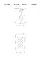
- the above sinteringis conducted generally in a state that, as shown in FIG. 5, (1) a setter 4 is placed in a sagger having a sealed structure [this sealed structure is for the prevention of incoming of contaminants (e.g. carbon, etc. which are furnace materials) as well as for the control of atmosphere], (2) two perforated plates 1a and 1b are arranged, by the use of jigs 5, in parallel to each other and also to the setter 4 with a given distance provided between the two perforated plates and with the lower perforated plate 1b contacted with the setter 4, and (3) tubes 2 are inserted into the holes of the two perforated plates 1a and 1b in parallel to each other and vertically to the floor surface.
- a setter 4is placed in a sagger having a sealed structure [this sealed structure is for the prevention of incoming of contaminants (e.g. carbon, etc. which are furnace materials) as well as for the control of atmosphere]
- two perforated plates 1a and 1bare arranged, by the
- the reason why the lower perforated plate is not directly placed on the sagger and the setter is provided between the lower perforated plate and the sagger,is that when sintering is conducted in a state that the sagger and the lower perforated plate are in contact with each other, the smooth shrinkage of the lower perforated plate during sintering is prevented by the friction between the sagger and the lower perforated plate, causing deformation of the lower perforated plate.
- sinteringis conducted generally in a state that a setter made of a material having about the same sintering shrinkage factor as the perforated plates (the material is basically the same as for the perforated plates) is placed between the sagger and the lower perforated plate.
- the perforated unsintered ceramic plates having a large sintering shrinkage factorcause shrinkage during the sintering to tighten the tubes, whereby joining between the plates and the tubes is achieved.
- the center of shrinkage of each plateis at the center of thickness of each plate, the lower plate 1b at the lower ends of the tubes rises from the setter 4 as shown in FIG. 6, during the sintering and, as a result, only the lower ends of the tubes 2 come into contact with the setter 4.
- the setter 4comes to support the total weight of the two plates 1a and 1b, the tubes 2 and the jigs 5 only at the small areas contacting with the tubes 2; the concentration of the total weight on the small contact areas destroys the setter 4; the destruction of the setter 4 incurs the cracking of the lower plate 1b.
- the present inventionhas been made in view of the above-mentioned problems of the prior art.
- the object of the present inventionis to produce an excellent joined ceramic component consisting of a plurality of parallel ceramic tubes and two perforated ceramic plates joined to the both ends of the tubes, by utilizing the difference in sintering shrinkage factor between the tubes and the plates, in which process the concentration of the total weight of plates, tubes and jigs on the limited small areas of setter during sintering and joining is eliminated and resultantly the destruction of setter and the cracking of lower plate are prevented.
- the present inventionprovides a process for producing a joined ceramic component having a plurality of parallel ceramic tubes and two perforated ceramic plates joined to the both ends of said ceramic tubes, which process comprises arranging, by an appropriate means, two unsintered ceramic plates each having a plurality of holes, in parallel to each other and also to the floor surface with a given distance provided between the upper plate and the lower plate, inserting a plurality of sintered ceramic tubes into the holes of the upper and lower plates so that the tubes are arranged vertically to the floor surface and in parallel to each other, and sintering the resulting component to join the tubes and the plates into one piece by utilizing the difference in sintering shrinkage factor between them, in which process the sintering is conducted in a state that each tube is hanged from the upper plate by an appropriate means and that the lower end of each tube is in one hole of the lower plate placed on or above a setter, with a certain distance provided between the lower end of each tube and the setter so that they do not come in contact with each other during the sinter
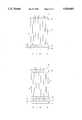
- FIG. 1is a side view showing an example of the present process for producing a joined ceramic component.
- FIG. 2is a side view showing other example of the present process for producing a joined ceramic component.
- FIG. 3is a side view showing a joined ceramic component.
- FIG. 4is a plan view of a perforated plate.
- FIG. 5is a side view showing the conventional process for producing a joined ceramic component.
- FIG. 6is a side view showing a certain stage during sintering in the conventional process for producing a joined ceramic component.
- sinteringis not conducted in the same manner as in the conventional process, i.e. in a state that, as shown in FIG. 5, the lower end of each tube 2 is inserted into one hole of a lower perforated plate 1b to the extent that said lower end is flush with the lower surface of the lower perforated plate 1b (in other words, said lower end is in contact with a setter 4); but sintering is conducted in a state that, as shown in FIG.
- each tube 2is hanged from an upper perforated plate 1a fixed by jigs 5 and that the lower end of each tube 2 is inserted into one hole of a lower perforated plate 1b placed on or above a setter 4 with a given distance provided between the lower end of each tube 2 and the setter 4.
- a given distancei.e. a given gap
- the lower perforated plate 1bcomes into face contact with the setter 4 or only the jigs come into contact with the setter 4 during the sintering. Consequently, the total weight of jigs, perforated plates and tubes is placed on the surface of the setter 4 not unevenly but almost uniformly, inviting neither setter destruction nor plate destruction.
- each tube 2is inserted into one hole of the upper-perforated plate 1a and hanged therefrom by placing the both ends of the pin 6 on the plate 1a; the lower end of each tube 2 is inserted into one hole of the lower perforated plate 1b to an appropriate depth of the hole.
- the distance between the lower end of each tube 2 and the setter 4i.e.
- the distance l between the lower end of each tube 2 and the upper surface of the setter 4is a distance determined beforehand by experiment or calculation so that the lower end of each tube 2 does not project from the lower surface of the lower perforated plate 1b when the plate 1b causes shrinkage during sintering.
- the upper end portion of each tube 2 projecting from the upper surface of the upper perforated plate 1acan be, if necessary, removed after sintering by cutting.
- FIG. 2shows other example of the specific means for hanging each tube from the upper perforated plate and providing a given distance between the lower end of each tube and the setter.
- the hanging of each tube 2is conducted in the same manner as in FIG. 1, but the lower perforated plate 1b and the setter 4 are separated by jigs 7 to provide a given distance l between the lower end of each tube 2 and the setter 4.
- the ceramic used in the present joined ceramic componentmay be any ceramic of oxide type or nonoxide type, and can be appropriately selected depending upon the requirements for the present joined ceramic component, i.e. the type, mechanical strengths, etc. of the structural member in which the present joined ceramic component is used.
- the present joined ceramic componentis used in, for example, engines, industrial machinery and heat exchangers, there is used, as the ceramic, silicon nitride or silicon carbide both of high strength and high heat resistance.
- the perforated plates and the tubesmay be made of the same ceramic or of different ceramics.
- each platemay be formed simultaneously with the molding-of the plate, or may be formed by punching, ultrasonic machining or the like after the molding of the plate.
- the settermay generally have the same shape as each plate does, except that the setter has no hole, and may be made of basically the same material as used for each plate.
- two green plateswere prepared using the same materials as used in the preparation of the tubes, by cold isostatic pressing (CIP) molding in which a pressure of 7 ton/cm 2 was applied.
- the green plateswere subjected to drying and calcination (to burn out the binder) under the same conditions as used in the preparation of the tubes. Further calcination was conducted in a nitrogen atmosphere at 1,350° C. for 3 hours to obtain two plates of 350 mm ⁇ 170 mm ⁇ 20 mm (thickness).
- the plateswere subjected to ultrasonic machining to form therein a plurality of holes (9.3 mm in diameter) for inserting the above tubes thereinto and effecting tube-plate joining, whereby two perforated plates were obtained.
- each tube 2was inserted into one hole of the upper perforated plate 1a placed on jigs 5 and, by placing the two ends of each pin on the upper surface of the upper perforated plate 1a , each tube 2 was hanged from the upper perforated tube 1a; and the lower end of each tube 2 was inserted into one hole of the lower perforated plate 1b placed on a setter 4, to a certain depth.
- the resulting assemblywas sintered in a nitrogen atmosphere at 1,600° C. for 3 hours to bond the perforated plates 1a and 1b and the tubes 2 into one piece.
- the setter 4was produced in the same manner as used for the perforated plates except that no hole was formed in the setter 4, and the jigs 5 were sintered tubes produced using the same materials as used in production of the tubes.
- the interference in joining by sinteringwas 0.2 mm.
- the upper end portion of each tube 2 projecting from the upper surface of the upper perforated plate 1awas cut off to obtain a joined ceramic component as shown in FIG. 3, consisting of tubes 2 and upper and lower perforated plates 1a and 1b joined to the both ends of the tubes 2.
- the perforated platesshowed no cracking.
- two green plateswere prepared using the same materials as used in the preparation of the tubes, by CIP molding in which a pressure of 7 ton/cm 2 was applied.
- the green plateswere subjected to drying and calcination (to burn out the binder) under the same conditions as used in the preparation of the tubes. Further calcination was conducted in a nitrogen atmosphere at 1,350° C. for 3 hours to obtain two plates of 350 mm ⁇ 170 mm ⁇ 20 mm (thickness).
- the plateswere subjected to ultrasonic machining to form therein a plurality of holes (9.3 mm in diameter) for inserting the above tubes thereinto and effecting tube-plate bonding, whereby two perforated plates were obtained.
- each tube 2was inserted into one hole of the upper perforated plate 1a placed on jigs 5 and, by placing the two ends of each pin on the upper surface of the upper perforated plate 1a, each tube 2 was hanged from the upper perforated tube 1a; and the lower end of each tube 2 was inserted into one hole of the lower perforated plate 1b separated from a setter 4 by the use of jigs 7.
- the resulting assemblywas fired in a nitrogen atmosphere at 1,600° C. for 3 hours to bond the perforated plates 1a and 1b and the tubes 2 into one piece.
- the setter 4was produced in the same manner as used for the perforated plates except that no hole was formed in the setter 4, and the jigs 5 were sintered tubes produced using the same materials as used in production of the tubes.
- the interference in joining by sinteringwas 0.2 mm.
- the upper end portion of each tube 2 projecting from the upper surface of the upper perforated plate 1awas cut off to obtain a joined ceramic component as shown in FIG. 3, consisting of tubes 2 and upper and lower perforated plates 1a and 1b joined to the both ends of the tubes 2.
- the perforated platesshowed no cracking.
- a joined ceramic componentwas produced in the same manner as in Examples except that sintering was conducted in a state that, as shown in FIG. 5, no pin was used and the lower end of each tube 2 was inserted into one hole of the lower perforated plate 1b so that the lower front end of each tube 2 was flush with the lower surface of the lower perforated plate 1b, that is, the lower front end of each tube 2 was in contact with a setter 4.
- the lower perforated plate 1bshowed cracking.
- the present inventionenables production of an excellent joined ceramic component consisting of a plurality of parallel ceramic tubes and two perforated ceramic plates bonded to the both ends of said tubes, by utilizing the difference in sintering shrinkage factor between said tubes and said plates, without inviting the destruction of setter and the consequent cracking of lower perforated plate during the sintering joining step.
Landscapes
- Chemical & Material Sciences (AREA)
- Engineering & Computer Science (AREA)
- Ceramic Engineering (AREA)
- Materials Engineering (AREA)
- Structural Engineering (AREA)
- Organic Chemistry (AREA)
- Manufacturing & Machinery (AREA)
- Inorganic Chemistry (AREA)
- Ceramic Products (AREA)
Abstract
Description
Claims (10)
Applications Claiming Priority (2)
| Application Number | Priority Date | Filing Date | Title |
|---|---|---|---|
| JP5-288324 | 1993-11-17 | ||
| JP5288324AJP2713688B2 (en) | 1993-11-17 | 1993-11-17 | Manufacturing method of ceramic joined body |
Publications (1)
| Publication Number | Publication Date |
|---|---|
| US5529651Atrue US5529651A (en) | 1996-06-25 |
Family
ID=17728712
Family Applications (1)
| Application Number | Title | Priority Date | Filing Date |
|---|---|---|---|
| US08/341,074Expired - Fee RelatedUS5529651A (en) | 1993-11-17 | 1994-11-17 | Process for production of joined ceramic body |
Country Status (3)
| Country | Link |
|---|---|
| US (1) | US5529651A (en) |
| JP (1) | JP2713688B2 (en) |
| DE (1) | DE4440842A1 (en) |
Cited By (9)
| Publication number | Priority date | Publication date | Assignee | Title |
|---|---|---|---|---|
| US5260365A (en)* | 1982-09-17 | 1993-11-09 | Dow Chemical Co | Liquid crystalline polymer compositions, process, and products |
| US5993985A (en)* | 1998-04-09 | 1999-11-30 | Siemens Westinghouse Power Corporation | Fuel cell tubes and method of making same |
| US6261708B1 (en)* | 1997-01-30 | 2001-07-17 | Ngk Insulators, Ltd. | Joined body of aluminum nitride series ceramics, method of joining aluminum nitride series ceramics and joining agent |
| US6481370B2 (en) | 1996-11-27 | 2002-11-19 | Hitachi, Ltd. | Plasma processsing apparatus |
| US20040129203A1 (en)* | 2001-05-18 | 2004-07-08 | Raanan Zehavi | Silicon tube formed of bonded staves |
| US20070006799A1 (en)* | 2001-05-18 | 2007-01-11 | Zehavi Ranaan Y | Silicon wafer support fixture with roughended surface |
| US20080291524A1 (en)* | 2003-11-01 | 2008-11-27 | Fusao Ishil | Mirror device |
| US20090311124A1 (en)* | 2008-06-13 | 2009-12-17 | Baker Hughes Incorporated | Methods for sintering bodies of earth-boring tools and structures formed during the same |
| US20180051874A1 (en)* | 2016-08-18 | 2018-02-22 | Clearsign Combustion Corporation | Cooled ceramic electrode supports |
Citations (9)
| Publication number | Priority date | Publication date | Assignee | Title |
|---|---|---|---|---|
| JPS55116681A (en)* | 1979-02-28 | 1980-09-08 | Ngk Insulators Ltd | Ceramic part bonding method |
| US4330496A (en)* | 1979-09-11 | 1982-05-18 | Compagnie Generale D'electricite | Method of sintering tubular ceramic parts |
| US4769097A (en)* | 1986-02-12 | 1988-09-06 | Kabushiki Kaisha Toshiba | Method of fixing member in ceramic body and a ceramic body with a member manufactured by the method |
| DE3831811A1 (en)* | 1988-09-19 | 1990-03-22 | Ewald Meiser | Process and apparatus for controlling the regeneration of water softening units |
| US4913754A (en)* | 1987-10-06 | 1990-04-03 | Lilliwyte Societe Anonyme | Manufacture of beta-alumina artifacts |
| DE4110141A1 (en)* | 1990-03-28 | 1991-10-02 | Ngk Insulators Ltd | CONNECTED CERAMIC CONSTRUCTION |
| US5106550A (en)* | 1987-05-13 | 1992-04-21 | Ngk Spark Plug Co., Ltd. | Method of producing ceramic rotor |
| US5106434A (en)* | 1985-02-18 | 1992-04-21 | Ngk Spark Plug Co., Ltd. | Method for producing a metal and ceramic heat-connected body |
| US5306368A (en)* | 1992-01-17 | 1994-04-26 | Ngk Insulators, Ltd. | Formation of ceramic thin film on ceramic body |
Family Cites Families (1)
| Publication number | Priority date | Publication date | Assignee | Title |
|---|---|---|---|---|
| DE3831812A1 (en)* | 1988-09-19 | 1990-03-22 | Interatom | Process for producing complicated components of silicon-infiltrated silicon carbide |
- 1993
- 1993-11-17JPJP5288324Apatent/JP2713688B2/ennot_activeExpired - Fee Related
- 1994
- 1994-11-15DEDE4440842Apatent/DE4440842A1/ennot_activeWithdrawn
- 1994-11-17USUS08/341,074patent/US5529651A/ennot_activeExpired - Fee Related
Patent Citations (11)
| Publication number | Priority date | Publication date | Assignee | Title |
|---|---|---|---|---|
| JPS55116681A (en)* | 1979-02-28 | 1980-09-08 | Ngk Insulators Ltd | Ceramic part bonding method |
| US4299638A (en)* | 1979-02-28 | 1981-11-10 | Ngk Insulators, Ltd. | Method of bonding silicon ceramic members |
| US4330496A (en)* | 1979-09-11 | 1982-05-18 | Compagnie Generale D'electricite | Method of sintering tubular ceramic parts |
| US5106434A (en)* | 1985-02-18 | 1992-04-21 | Ngk Spark Plug Co., Ltd. | Method for producing a metal and ceramic heat-connected body |
| US4769097A (en)* | 1986-02-12 | 1988-09-06 | Kabushiki Kaisha Toshiba | Method of fixing member in ceramic body and a ceramic body with a member manufactured by the method |
| US5106550A (en)* | 1987-05-13 | 1992-04-21 | Ngk Spark Plug Co., Ltd. | Method of producing ceramic rotor |
| US4913754A (en)* | 1987-10-06 | 1990-04-03 | Lilliwyte Societe Anonyme | Manufacture of beta-alumina artifacts |
| DE3831811A1 (en)* | 1988-09-19 | 1990-03-22 | Ewald Meiser | Process and apparatus for controlling the regeneration of water softening units |
| DE4110141A1 (en)* | 1990-03-28 | 1991-10-02 | Ngk Insulators Ltd | CONNECTED CERAMIC CONSTRUCTION |
| US5209525A (en)* | 1990-03-28 | 1993-05-11 | Ngk Insulators, Ltd. | Bonded ceramic structure |
| US5306368A (en)* | 1992-01-17 | 1994-04-26 | Ngk Insulators, Ltd. | Formation of ceramic thin film on ceramic body |
Non-Patent Citations (2)
| Title |
|---|
| Patent Abstracts of Japan, C 1034, Mar. 12, 1993, vol. 17, No. 119; JP A 4 300262, Siliceous Carbide Jig.* |
| Patent Abstracts of Japan, C-1034, Mar. 12, 1993, vol. 17, No. 119; JP-A 4-300262, "Siliceous Carbide Jig." |
Cited By (13)
| Publication number | Priority date | Publication date | Assignee | Title |
|---|---|---|---|---|
| US5260365A (en)* | 1982-09-17 | 1993-11-09 | Dow Chemical Co | Liquid crystalline polymer compositions, process, and products |
| US6481370B2 (en) | 1996-11-27 | 2002-11-19 | Hitachi, Ltd. | Plasma processsing apparatus |
| US6261708B1 (en)* | 1997-01-30 | 2001-07-17 | Ngk Insulators, Ltd. | Joined body of aluminum nitride series ceramics, method of joining aluminum nitride series ceramics and joining agent |
| US5993985A (en)* | 1998-04-09 | 1999-11-30 | Siemens Westinghouse Power Corporation | Fuel cell tubes and method of making same |
| US20070006799A1 (en)* | 2001-05-18 | 2007-01-11 | Zehavi Ranaan Y | Silicon wafer support fixture with roughended surface |
| US7137546B2 (en)* | 2001-05-18 | 2006-11-21 | Integrated Materials, Inc. | Silicon tube formed of bonded staves |
| US20040129203A1 (en)* | 2001-05-18 | 2004-07-08 | Raanan Zehavi | Silicon tube formed of bonded staves |
| US20070020885A1 (en)* | 2001-05-18 | 2007-01-25 | Integrated Materials, Inc. | Tube Formed of Bonded Silicon Staves |
| US7854974B2 (en) | 2001-05-18 | 2010-12-21 | Integrated Materials, Inc. | Tube formed of bonded silicon staves |
| US20080291524A1 (en)* | 2003-11-01 | 2008-11-27 | Fusao Ishil | Mirror device |
| US20090311124A1 (en)* | 2008-06-13 | 2009-12-17 | Baker Hughes Incorporated | Methods for sintering bodies of earth-boring tools and structures formed during the same |
| US20180051874A1 (en)* | 2016-08-18 | 2018-02-22 | Clearsign Combustion Corporation | Cooled ceramic electrode supports |
| US10619845B2 (en)* | 2016-08-18 | 2020-04-14 | Clearsign Combustion Corporation | Cooled ceramic electrode supports |
Also Published As
| Publication number | Publication date |
|---|---|
| DE4440842A1 (en) | 1995-05-18 |
| JP2713688B2 (en) | 1998-02-16 |
| JPH07144975A (en) | 1995-06-06 |
Similar Documents
| Publication | Publication Date | Title |
|---|---|---|
| US5529651A (en) | Process for production of joined ceramic body | |
| EP0929207A3 (en) | Multi-layer ceramic substrate and method for producing the same | |
| EP0798532A2 (en) | Ceramic shell-and-tube type heat exchanger and method for manufacturing the same | |
| JP2882996B2 (en) | Jig for manufacturing ceramic joined body and method for manufacturing ceramic joined body using the jig | |
| US4215088A (en) | Method for fabricating boron carbide articles | |
| US6006824A (en) | Ceramic shell-and-tube type heat exchanger, and method for manufacturing it | |
| JP2802013B2 (en) | Ceramic joining method | |
| JP2878923B2 (en) | Manufacturing method of ceramic joined body | |
| JP2738900B2 (en) | Manufacturing method of ceramic joined body | |
| JP2801947B2 (en) | Ceramic joint | |
| JP2863055B2 (en) | Manufacturing method of ceramic joined body | |
| KR19980018348A (en) | Ceramic Joints and Manufacturing Method Thereof | |
| JPH07270093A (en) | Ceramic shell and tube type heat exchanger and manufacture thereof | |
| JP2716930B2 (en) | Manufacturing method of ceramic joined body | |
| JP2813105B2 (en) | Manufacturing method of ceramic joined body | |
| JP2883003B2 (en) | Manufacturing method of ceramic joined body | |
| JP3099043B2 (en) | Jig for ceramic firing and manufacturing method thereof | |
| JP4259647B2 (en) | Ceramic firing jig and manufacturing method thereof | |
| JPH02296778A (en) | Production of ceramic superconductor | |
| JPH02279570A (en) | Method for manufacturing ceramic structures | |
| JP2771306B2 (en) | Ceramic joint | |
| JPS623834A (en) | Joined body of ceramic member and metal member and its manufacturing method | |
| JP3040203U (en) | Boron nitride compact setter for large area ceramics sintering | |
| JP2002255666A (en) | Joint and method for manufacturing the same | |
| JPH0629444B2 (en) | Sintering method |
Legal Events
| Date | Code | Title | Description |
|---|---|---|---|
| AS | Assignment | Owner name:NGK INSULATORS, LTD., JAPAN Free format text:ASSIGNMENT OF ASSIGNORS INTEREST;ASSIGNORS:YOSHIDA, TOSHIHIRO;WATANABE, KEIICHIRO;REEL/FRAME:007211/0922 Effective date:19941104 | |
| FEPP | Fee payment procedure | Free format text:PAYOR NUMBER ASSIGNED (ORIGINAL EVENT CODE: ASPN); ENTITY STATUS OF PATENT OWNER: LARGE ENTITY | |
| FEPP | Fee payment procedure | Free format text:PAYER NUMBER DE-ASSIGNED (ORIGINAL EVENT CODE: RMPN); ENTITY STATUS OF PATENT OWNER: LARGE ENTITY | |
| AS | Assignment | Owner name:NEW ENERGY AND INDUSTRIAL TECHNOLOGY DEVELOPMENT O Free format text:ASSIGNMENT OF ASSIGNORS INTEREST;ASSIGNOR:NGK INSULATORS, LTD.;REEL/FRAME:009648/0830 Effective date:19981130 | |
| FEPP | Fee payment procedure | Free format text:PETITION RELATED TO MAINTENANCE FEES FILED (ORIGINAL EVENT CODE: PMFP); ENTITY STATUS OF PATENT OWNER: LARGE ENTITY | |
| FEPP | Fee payment procedure | Free format text:PETITION RELATED TO MAINTENANCE FEES GRANTED (ORIGINAL EVENT CODE: PMFG); ENTITY STATUS OF PATENT OWNER: LARGE ENTITY | |
| REMI | Maintenance fee reminder mailed | ||
| FP | Lapsed due to failure to pay maintenance fee | Effective date:20000625 | |
| FPAY | Fee payment | Year of fee payment:4 | |
| SULP | Surcharge for late payment | ||
| PRDP | Patent reinstated due to the acceptance of a late maintenance fee | Effective date:20000915 | |
| FPAY | Fee payment | Year of fee payment:8 | |
| REMI | Maintenance fee reminder mailed | ||
| LAPS | Lapse for failure to pay maintenance fees | ||
| STCH | Information on status: patent discontinuation | Free format text:PATENT EXPIRED DUE TO NONPAYMENT OF MAINTENANCE FEES UNDER 37 CFR 1.362 | |
| FP | Lapsed due to failure to pay maintenance fee | Effective date:20080625 |