US5529465A - Micro-miniaturized, electrostatically driven diaphragm micropump - Google Patents
Micro-miniaturized, electrostatically driven diaphragm micropumpDownload PDFInfo
- Publication number
- US5529465A US5529465AUS08/204,265US20426594AUS5529465AUS 5529465 AUS5529465 AUS 5529465AUS 20426594 AUS20426594 AUS 20426594AUS 5529465 AUS5529465 AUS 5529465A
- Authority
- US
- United States
- Prior art keywords
- diaphragm
- pump body
- pump
- fluid
- micropump according
- Prior art date
- Legal status (The legal status is an assumption and is not a legal conclusion. Google has not performed a legal analysis and makes no representation as to the accuracy of the status listed.)
- Expired - Fee Related
Links
Images


Classifications
- F—MECHANICAL ENGINEERING; LIGHTING; HEATING; WEAPONS; BLASTING
- F04—POSITIVE - DISPLACEMENT MACHINES FOR LIQUIDS; PUMPS FOR LIQUIDS OR ELASTIC FLUIDS
- F04B—POSITIVE-DISPLACEMENT MACHINES FOR LIQUIDS; PUMPS
- F04B43/00—Machines, pumps, or pumping installations having flexible working members
- F04B43/02—Machines, pumps, or pumping installations having flexible working members having plate-like flexible members, e.g. diaphragms
- F04B43/04—Pumps having electric drive
- F04B43/043—Micropumps
- F04B43/046—Micropumps with piezoelectric drive
- F—MECHANICAL ENGINEERING; LIGHTING; HEATING; WEAPONS; BLASTING
- F04—POSITIVE - DISPLACEMENT MACHINES FOR LIQUIDS; PUMPS FOR LIQUIDS OR ELASTIC FLUIDS
- F04B—POSITIVE-DISPLACEMENT MACHINES FOR LIQUIDS; PUMPS
- F04B53/00—Component parts, details or accessories not provided for in, or of interest apart from, groups F04B1/00 - F04B23/00 or F04B39/00 - F04B47/00
- F04B53/10—Valves; Arrangement of valves
- F04B53/1037—Flap valves
- F04B53/1047—Flap valves the valve being formed by one or more flexible elements
- F04B53/1055—Flap valves the valve being formed by one or more flexible elements more than two flexible elements oscillating around a fixed point
Definitions
- the present inventionrelates to a micro-miniaturized, electrostatically driven diaphragm micropump.
- thermopneumatically driven diaphragm micropumpis described. The realization of such a drive is very expensive.
- Piezoelectrically driven diaphragm pumpsare explained in detail in the technical publications F. C. M. van de Pol, H. T. G. van Lintel, S. Bouwstra, "A Piezoelectric Micropump Based on Micromachining of Silicon", Sensors and Actuators, 19 (1988), pages 153-167 and M. Esashi, S. Shoji and A. Nakano, "Normally closed Microvalve and Micropump", Sensors and Actuators, 20 (1989), 163-169.
- the realization of these drive meansincludes manufacturing steps which do not belong to the standard technology steps of semiconductor technology, such as the step of glueing on a piezo film or a piezo stack, so that the manufacturing costs are high.
- U.S. Pat. No. 5,085,562already discloses a microminiaturized diaphragm pump having an outer diaphragm which is adapted to be deformed by a piezoelement.
- An inner pump chamber of the micropumpis subdivided by a partition within which valve structures are arranged.
- the valves structuresare a constituent part of stop means which limit the movement of the diaphragm relative to the partition or relative to the rest of the pump body so as to determine a constant amount of medium pumped per pumping cycle.
- U.S. Pat. No. 5,224,843discloses an additional micropump whose structure largely corresponds to the micropump which has just been assessed hereinbefore.
- U.S. Pat. No. 5,336,062discloses a micropump comprising a first pump body and a second pump body having a diaphragm region; each of said pump bodies have electrically conductive electrode areas which are adapted to be connected to a voltage source and which are electrically insulated from each other, said two pump bodies defining together a pump chamber bordering on the diaphragm region.
- the pump capacity of this micropumpis not always satisfactory. The fact that the liquid to be pumped is acted upon by an electric field is in some cases unwanted.
- an electrostatically driven diaphragm micropumpcomprising:
- first pump body and a second pump bodyhaving a diaphragm region, said pump bodies having each electrically conductive electrode areas which are adapted to be connected to a voltage source and which are electrically insulated from one another, and
- a pump chamberprovided with a flow direction control means and having a flow resistance which depends on the flow direction of the fluid to be pumped, wherein
- the two pump bodiesdefine together a hollow space bordering on the diaphragm region
- the hollow spaceis filled with a fluid medium which is spatially separated from the fluid to be pumped, and
- the hollow spaceis arranged between the electrically conductive electrode area of the first pump body and the electrically conductive electrode area of the second pump body so that the fluid medium will be acted upon by the electric field generated between said electrically conductive electrode areas of the pump bodies, whereas the fluid to be pumped will not, or only to a minor extent be acted upon by said electric field.
- micro-miniaturized diaphragm micropumpwhich can be produced easily and at a reasonable price and which has a high pump capacity.
- an electrostatically driven diaphragm micropumpcomprising:
- first pump body and a second pump bodyhaving a diaphragm region, said pump bodies having each electrically conductive electrode areas which are adapted to be connected to a voltage source and which are electrically insulated from one another, and
- a pump chamberprovided with a flow direction control means and having a flow resistance which depends on the flow direction of the fluid to be pumped, wherein
- the two pump bodiesdefine together a hollow space bordering on the diaphragm region
- the hollow spaceis filled with a fluid medium which is spatially separated from the fluid to be pumped, said fluid medium having a relative dielectric constant which is higher than 1.
- the medium to be pumpedis prevented from being exposed to the influence of the electrostatic field required as a drive means so that the diaphragm micropump according to the present invention can also be used for dosing medicaments which dissociate under the influence of electrostatic fields.
- the diaphragm micropumpis able to transport liquids and/or gases as well as to generate a hydrostatic pressure when the flow rate is zero.
- the diaphragm micropump according to the present inventioncan, and this is a great advantage, be produced with the known methods used in the field of semiconductor technology.
- An additional advantage of the diaphragm micropump according to the present inventionis to be seen in the fact that it can be used for transporting fluids of arbitrary conductivity
- a typical field of use of the diaphragm micropump according to the present inventionis, for example, the precise dosage of liquids in the microliter and sub-microliter range in the medical sphere, or in technical fields, such as mechanical engineering.
- the diaphragm micropumpcomprises a hollow space defined by the two pump bodies and bordering on the diaphragm region, said hollow space being filled with a fluid medium which is spatially separated from the fluid to be pumped.
- the hollow spacepreferably has at least one opening through which said medium can flow out.
- the diaphragm micropumpcomprises a hollow space defined by the two pump bodies and bordering on the diaphragm region, said hollow space being filled with a fluid medium which is spatially separated from the fluid to be pumped; said fluid medium has a relative dielectric constant which is higher than 1.
- the hollow spacepreferably has at least one opening through which said medium can flow out.
- the mediumwhich can also be referred to as an intensifying liquid or intensifying gas, preferably has a relative dielectric constant which is as high as possible so as to produce the strongest possible force which acts on the diaphragm region when a voltage is applied to the two pump bodies.
- the fluidcan be enclosed by the housing of the diaphragm micropump, and, consequently, it need not necessarily come into contact with its surroundings.
- this liquidmust not fill the hollow space in the housing completely, taking into account its infinitely small compressibility, since otherwise an escape of the liquid from the space between the first and second pump bodies (diaphragm region/ counterelectrode body) will no longer be possible and the diaphragm would no longer move due to the counterpressure built up by the liquid.
- embodimentscan also be taken into account in which the hollow space is filled completely with the intensifying liquid; in this case, the opening of the hollow space is, however, isolated from the ambient atmosphere by an extremely flexible additional diaphragm, which may consist e.g. of a rubber skin.
- the pumpcan also be operated with an intensifying gas having a dielectric constant which is higher than 1.
- One or more passage openings in the counterelectrode bodyguarantee that, when a liquid is used as an intensifying means, said liquid can flow into and out of the space between the first and the second pump body (diaphragm region/counterelectrode body) without having to overcome any major resistance.
- an increased pumping frequency of the electrostatic diaphragm micropump according to the present inventioncan be obtained by facilitating the flowing off of the intensifying liquid in the direction of the passage opening through channel structures in the diaphragm or the pump body located opposite the diaphragm.
- dielectrics having a high dielectric constantwill displace dielectrics having a lower dielectric constant in a capacitor guarantees that the liquid will automatically fill the space between the first and the second pump body (diaphragm/counterelectrode) provided that only one of the above-mentioned passage openings is in contact with the liquid filling.
- This filling processcan additionally be facilitated by an adequate surface coating of the first and second pump bodies, at least in the areas of the diaphragm region coming into contact with the liquid, and of the third pump body as a counterelectrode.
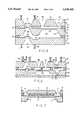
- FIG. 1shows a schematic sectional view for explaining the operating principle of an, electrostatic diaphragm micropump according to the present invention
- FIG. 2shows in a schematic representation a cross-section through a first embodiment of an electrostatically driven diaphragm micropump according to the present invention
- FIG. 3ashows a sectional view of a third pump body composed of two sub-pump bodies which are provided with valves;
- FIG. 3bshows a sectional view of an alternative embodiment of the pump body structure according to FIG. 3a;
- FIG. 4shows a different structural design of a first pump body
- FIG. 5shows a schematic sectional view of a different structural design of an electrostatic diaphragm micropump according to the present invention
- FIG. 6shows a schematic sectional view of an additional embodiment of an electrostatic diaphragm micropump according to the present invention
- FIG. 7shows a modification of the embodiment according to FIG. 1;
- FIG. 8shows a graphic representation of the connection between rate of flow and pressure difference for the valves used in the embodiment according to FIG. 3b.
- FIG. 1shows a subunit of a micro-miniaturized electrostatically driven diaphragm pump according to the present invention, which is designated generally by reference numeral 1.
- a first pump body 2, which serves as an electrode area,is arranged above a second pump body 3 and is fixedly connected thereto.
- Second pump body 3has a portion which serves as another electrode area.
- Both pump bodies 2 and 3consist preferably of semiconductor materials of different charge carrier types.
- the first pump body 2can, for example, consist of p-type silicon, the second pump body 3 being then made of n-type silicon.
- the surface of the second pump body 3 facing the first pump body 2is coated with a dielectric layer.
- the side of the second pump body 3 facing away from the first pump body 2is provided with a recess 7 which has the shape of a truncated pyramid and by means of which a thin, elastic diaphragm region 6 of small thickness is created.
- the recess 7can be produced by photolithographic determination of a rear etch opening and by subsequent anisotropic etching.
- the first pump body 2has two passage openings 4 and 5 extending therethrough in the direction of its thickness. These two passage openings taper towards the second pump body 3.
- first and second pump bodies 2 and 3are sealingly interconnected via a connection layer 9 whereby a space 10 is formed.
- the connection layer 9may consist e.g. of Pyrex glass.
- the connectioncan be established by anodic bonding or by means of glueing.
- the distance d1 between the two surfaces of the first and second pump bodies 2 and 3 facing each othershould be approximately in the range of from 1 to 20 micrometers.
- the space 10 between the first and second pump bodies 2 and 3is filled with a fluid medium having a suitably high dielectric constant to such an extent that the liquid will extend up to and into the passage openings 4 and 5 or beyond said passage openings.
- the first pump body 2 or both pump bodies 2 and 3may just as well be coated with a passivating dielectric layer 8 having an overall thickness d2 and the relative dielectric constant 2 , e.g. for preventing electric breakdowns.
- the dielectriccan also fulfil the function of providing an advantageous surface tension for a specific liquid on the surfaces of the two pump bodies and 3 which face each other.
- the surface of the first pump body 2is provided with an ohmic contact 11 and the surface of the second pump body 3 is provided with an ohmic contact 11'. These two contacts 11 and 11' are connected to the terminals of a voltage source U.
- the passage openings 4 and 5 formed in the first pump body 2guarantee that the liquid can flow off unhindered from the space between the diaphragm region 6 of the second pump body 3 and the first pump body 2 and will thus not apply any counterpressure to the diaphragm region 6, which would prevent said diaphragm region 6 from moving in response to the electrostatically generated pressure.
- equation (1)shows that the thickness d 2 of a possible passivation layer 8 should not exceed a specific value ( 1 d 2 ⁇ 2 d 1 ).
- the electrostatically generated pressure acting on the diaphragm regionis practically stored in the diaphragm due to the deformation thereof and, when the voltage U has been switched off, it will have the effect that the diaphragm returns to its original position.
- a stroke volume of the pumpwhich, as far as possible, is independent of or depends only very little on the counterpressure which has to be overcome by the liquid will be of great advantage for dosing small amounts of liquids.
- the properties of the electrostatic diaphragm pump according to the present inventionwhich will be explained hereinbelow cause a constant stroke volume in a very elegant way.
- the diaphragm drive of the pump according to FIG. 1can be regarded as a series connection of two or more capacitances C 1 , C 2 . This is evident when, in FIG. 1, the boundary surface between the insulating layer 8 and the hollow space 10, which is filled with the liquid, is regarded as a fictitious capacitor plate.
- the capacitance C 2is represented by the insulating layer 8
- the capacitance C 1is represented by the liquid medium in the hollow space 10. This can be expressed by the following equation: ##EQU3##
- the diaphragmis only deflected up to a specific critical distance d 1 , and this corresponds to a defined stroke volume. It follows that, by adapting the thickness of the insulating layer 8, it is possible to achieve, at sufficiently high operating voltages U 0 , a pressure-independent stroke volume up to a specific maximum counterpressure p which has to be overcome; this is a great advantage as far as the precise dosage of liquids is concerned.
- FIG. 2shows, in a schematic representation, a cross-section through a first, particularly simple embodiment of an electrostatically operating diaphragm pump according to the present invention.
- This diaphragm pumpcomprises the subunit 1, which has been described in connection with FIG. 1 and which includes first and second pump bodies 2 and 3, respectively, and, in addition, a third pump body 12 which is connected to the second pump body 3 by an electrically conductive and sealing connection.
- This connectioncan be produced e.g. by soldering or by eutectic bonding or by means of glueing.
- the third pump body 12consists preferably of a semiconductor material of the same type as that of the second pump body 3, e.g. of n-type silicon.
- the first and the third pump bodies 2 and 12each have on the outer surface thereof an ohmic contact 13 and 14, respectively, and each of said ohmic contacts is connected to a terminal of a voltage source U.
- the third pump body 12is provided with two passage openings 15 and 16; passage opening 15 serves as a fluid inlet and passage opening 16 serves as a fluid outlet. Both passage openings 15 and 16 taper in the direction of flow of the fluid.
- check valverefers quite generally to a means characterized by different flow-through behaviours in different directions.
- the third pump body 12covers the recess 7 in the second pump body thus defining a hollow space 19, the pump chamber.
- the free surface of the third pump body 12has attached thereto a hose 20 connected to the passage opening 15 for supplying a fluid and a hose 21 connected to the passage opening 16 for discharging a fluid.
- a hose 20connected to the passage opening 15 for supplying a fluid
- a hose 21connected to the passage opening 16 for discharging a fluid.
- hoseit would also be possible to attach a suitable fluid line.
- the check valves in the third pump body 12can be defined by passage openings which are spanned by a diaphragmlike thin layer, which, in turn, is provided with passage openings provided in spaced relationship with the passage opening extending through the pump body chip.
- Such a structurecan, for example, be produced by the sacrificial-layer technology.
- These check valvescan either both be realized on one pump body chip, or they can be realized on two separate pump body chips, which are placed one on top of the other and bonded.
- the diaphragms spanning the passage openingsmay also be set back by surface recesses relative to the surface of the third pump body 12 and thus be protected more effectively.
- FIG. 3aAnother embodiment of the check valve within the framework of the present invention is shown in FIG. 3a.
- the third pump body 12 of the diaphragm pump shown in FIG. 2is defined by two identical subcomponents 22a and 22b, which are interconnected in a head-to-head arrangement via a thin connection layer 23 only in the marginal regions and in the central regions thereof.
- the surfaces of the two subcomponents 22a and 22b facing each otherare spaced apart.
- connection layer 23can be dispensed with.
- the subcomponents 22a, 22bare glued together at their end faces.
- Each of the two subcomponents 22a and 22bis provided with a passage opening 24a and 24b, respectively, whose structural design is similar to that of the passage openings 15 and 16 of the third pump body 12. Furthermore, each of the two subcomponents 222a and 22b is provided with an additional passage opening 25a and 25b, respectively, which has a special structural design.
- the additional passage openings 25a and 25bhave the same structural design so that it will suffice to describe only one of the passage openings 25a.
- the passage opening 25acomprises a recess 26 which has the shape of a truncated pyramid and a preferably rectangular cross-section tapering in the direction of the free surface of subcomponent 22a.
- Subcomponent 22ais provided with a total number of four thin elastic connecting webs 27 on the side facing away from subcomponent 22b, only two of said connecting webs being shown in a, sectional view; these connecting webs are formed integrally with subcomponent 22a and they extend into the recess 26.
- the connecting webs 27have a thickness of approx. 0.5 to 30 ⁇ m.
- each connecting web 27 which projects into the recess 26is followed by a lamellar portion 28 formed integrally with said free edge portion and extending in the direction of subcomponent 22b.
- a lamellar portion 28formed integrally with said free edge portion and extending in the direction of subcomponent 22b.
- four lamellar portionsare provided, the two lamellar portions 28 shown in a sectional view and the other two which are not shown, said lamellar portions being, on the whole, arranged in such a way that they approach one another, their end faces 29 being positioned in the plane of the surface of subcomponent 22a facing subcomponent 22b.
- Electric contacting of the whole diaphragm pumpcan generally be effected by bonding or by means of the housing on the upper side of the first pump body and because of the electrically conductive connection between the second and third pump bodies--on the underside of the third pump body.
- the whole inner side of the pump chamber 19can be metallized and earthed via the contacting on the third pump body. This will have the effect that the medium to be pumped is not exposed to any electrostatic field while passing through the pump chamber 19. This may be of importance with respect to medical applications.
- FIG. 3bshows a modification of the embodiment according to FIG. 3a.
- identical reference numeralshave been used for identical parts so that it will not be necessary to explain these parts again.
- the connecting webs 27 and the lamellar portions 28 of the embodiment according to FIG. 3aare no longer provided.
- valve flaps 28a, 28bare formed integrally with the subcomponents 22a, 22b and arranged on the sides of these subcomponents 22a, 22b which face each other.
- the subcomponents 22a, 22bcan be etched together with the valve flaps 28a, 28b; these valve structures may consist of identical semiconductor chips bonded in a head-to-head arrangement.
- each chiphas an area in which it is etched thin so as to form the flap 28a, 28b having a typical flap thickness of 1 ⁇ m to 20 ⁇ m, and an area in which the opening 24a, 24b is etched through.
- Typical lateral dimensions of the flaps 28a, 28bare approx. 1 ⁇ 1 mm.
- a typical size of the opening on the smaller sideis approx. 400 ⁇ m ⁇ 400 ⁇ m.
- the two flaps 28a, 28bare very elastic so that, depending on the direction of the pressure acting thereon, they will be pressed onto the opening 24a, 24b in one case and urged away from said opening in the other.
- FIG. 8shows a graphic representation of the rate of flow through the pump body valve structure according to FIG. 3b in response to the pressure difference. It can be seen that the valve structure according to FIG. 3b is characterized by a very high forward-to-backward ratio. This characteristic feature of the valve structure becomes particularly apparent in the flow rate/pressure difference dependence for little flow rates which is drawn on a different scale and which is incorporated in FIG. 8.
- FIG. 4shows an additional embodiment, which is similar to that shown in FIG. 1. Identical reference numerals have been used for parts having the same meaning.
- the stroke volume of the diaphragmdepends on the net pressure acting on the diaphragm region. On the one hand, it is primarily the electrostatically generated pressure and, consequently, the operating voltage U which are of importance, and, on the other hand, the hydrostatic pressure difference ⁇ P, which has to be overcome by the fluid to be pumped, is to be considered. It follows that, when a fixed operating voltage is used, the stroke volume of the diaphragm or of the diaphragm region primarily depends on ⁇ p, and this is not desirable for many cases of use.
- insulating elements 30,which are arranged in a netlike configuration, may be provided on the surface of the first pump body 2 facing the diaphragm region 6 of the second pump body 3, said first pump body 2 acting as a counterelectrode and said insulating elements 30 being provided as an alternative to or in addition to the electrostatic boundary described.
- These insulating elements 30limit the stroke volume of the diaphragm region 6 bulging during the pumping operation and they have the effect that the stroke volume is almost pressure independent in the range of small pressure differences ⁇ P, as has been explained with reference to FIG. 1 (cf. equation 3).
- FIG. 5shows a different embodiment of an electrostatic diaphragm pump according to the present invention where, in contrast to the diaphragm pump shown in FIG. 2, the fluid inlet opening and the fluid outlet opening are located on opposite sides of the diaphragm pump.
- the diaphragm pump in FIG. 5is designated generally by reference numeral 31 and comprises first, second and third pump bodies 32, 33 and 34, respectively.
- the first and second pump bodies 32 and 33 and the second and third pump bodies 33 and 34are respectively interconnected via a connection layer 35 and 36 in their marginal regions.
- the distance between the individual pump bodiesis determined by the thickness of the connection layer 35 and 36, respectively.
- the connection layercan consist e.g. of Pyrex glass or of a solder.
- the first pump body 32is provided with an ohmic contact 37 and the third pump body is provided with an ohmic contact 38 for connection with a voltage source.
- the second pump body 33has a recess 44 on the side facing the third pump body 34, said recess 44 corresponding to the recess 7 provided in the second pump body 3 according to FIG. 2. Due to said recess 44, a thin, elastic diaphragm region 45 is defined.
- the second pump body 33is provided with a passage opening 46 which is spaced apart from the recess 44 and which is in alignment with the passage opening 41 in the first pump body 32.
- the passage opening 46has the shape of a truncated pyramid and tapers in the direction of the first pump body 33.
- the third pump body 34has a passage opening 47 which has the shape of a truncated pyramid and which tapers in the direction of the second pump body 33.
- the passage opening 47is in alignment with the passage opening 46 in the second pump body 33.
- a rear recess 44 in the second pump body 33 and the surface of the third pump body 34 facing the second pump body 33define a pump chamber 48.
- a recessis formed in the third pump body 34, whereby a connection passage 49 is defined between the pump chamber 48 and the area of the passage opening 46.
- this connection passage 49permits the fluid to be pumped to pass more easily from the pump chamber 48 into the area of the passage opening 46.
- a supply hose 50is secured to the free side of the third pump body 34 and connected to the passage opening 47 which serves as a fluid inlet opening.
- a discharge hose 51is secured to the free side of the first pump body 32 and connected to the passage opening 41 which serves as a fluid outlet opening.
- the passage opening 47 in the third pump body 34is provided with a check valve 52 on the side facing the second pump body 33.
- the passage opening 46 in the second pump body 33is provided with a check valve 53 on the side facing the first pump body 32.
- an overpressure and an underpressureare generated alternately between the two check valves 52 and 53 in the area of the passage opening 46.
- the check valve 52will be closed and the check valve 53 will be opened so that fluid to be pumped will be discharged from the passage opening 41.
- the check valve 53will be closed and the check valve 52 will be opened so that fluid to be pumped can now flow through the passage opening 47 and the connection passage 49 into the pump chamber 48.
- the first pump body 32 acting as a counterelectrodeconsists preferably of a p-type semiconductor substrate polished on one side, the second pump body 33 of an n-type semiconductor substrate polished on both sides, and the third pump body 34 of an n-type semiconductor substrate polished on one side.
- the diaphragm pump according to FIG. 6is designated generally by reference numeral 60 and comprises first and second pump bodies 61, 62 as well as a cover plate 63.
- the first pump body 61has two passage openings 64, 65 for the fluid to be pumped as well as two passage openings 66, 67 for the intensifying fluid having the high dielectric constant, the two last-mentioned passage openings 66, 67 bordering on the hollow space 68.
- a diaphragm region 69 of the second pump body 62is provided below the hollow space 68.
- the two pump bodies 61, 62are interconnected by a connection layer 70 in their peripheral areas as well as in marginal areas of the hollow space 68.
- the second pump body 62defines together with the cover plate 63 a pump chamber 71 extending up to the diaphragm region 69 on the one hand and merging with passage openings 72, 73 on the other.
- the first pump body 61carries a first valve flap 74 in the area of its second passage opening 65, said valve flap 74 defining together with the passage opening 65 a check valve.
- the second pump bodycarries a second valve flap 75 defining together with the second passage opening 73 an additional check valve.
- the first and second passage openings 64, 65 of the first pump body 61are followed by the two fluid connections 76, 77.
- FIG. 7shows a modification of the embodiment according to FIG. 1. Identical reference numerals have again been used for parts of the embodiment according to FIG. 7 which correspond to those of FIG. 1.
- the embodiment according to FIG. 7essentially differs from that according to FIG. 1 insofar as the diaphragm region 6 of the second pump body 3 and the oppositely located counterelectrode region 11 of the first pump body 2 have a riblike or comblike structure when seen in a cross-sectional view.
- an increase in the electrostatic force acting on the diaphragm 6will be achieved by this riblike or comblike structure.
- the diaphragm pumpcontains in its hollow space a liquid, which is acted upon by the electric field as a fluid medium, and pumps a liquid
- a gassuch as air
- the hollow spacemay be filled with a fluid medium whose relative dielectric constant is 1 or smaller than 1. Air may be used as such a fluid medium.
Landscapes
- Engineering & Computer Science (AREA)
- Mechanical Engineering (AREA)
- General Engineering & Computer Science (AREA)
- Reciprocating Pumps (AREA)
Abstract
Description
Claims (25)
Applications Claiming Priority (5)
| Application Number | Priority Date | Filing Date | Title |
|---|---|---|---|
| DE4130211.7 | 1991-09-11 | ||
| DE4130211 | 1991-09-11 | ||
| DE4135655.1 | 1991-10-29 | ||
| DE4135655ADE4135655A1 (en) | 1991-09-11 | 1991-10-29 | MICROMINIATURIZED, ELECTROSTATICALLY OPERATED DIAPHRAGM PUMP |
| PCT/DE1992/000630WO1993005295A1 (en) | 1991-09-11 | 1992-07-28 | Micro-miniaturised, electrostatically driven diaphragm micropump |
Publications (1)
| Publication Number | Publication Date |
|---|---|
| US5529465Atrue US5529465A (en) | 1996-06-25 |
Family
ID=25907199
Family Applications (1)
| Application Number | Title | Priority Date | Filing Date |
|---|---|---|---|
| US08/204,265Expired - Fee RelatedUS5529465A (en) | 1991-09-11 | 1992-07-28 | Micro-miniaturized, electrostatically driven diaphragm micropump |
Country Status (5)
| Country | Link |
|---|---|
| US (1) | US5529465A (en) |
| EP (1) | EP0603201B1 (en) |
| KR (1) | KR0119362B1 (en) |
| DE (3) | DE4143343C2 (en) |
| WO (1) | WO1993005295A1 (en) |
Cited By (167)
| Publication number | Priority date | Publication date | Assignee | Title |
|---|---|---|---|---|
| US5820772A (en)* | 1997-01-21 | 1998-10-13 | Ford Motor Company | Valveless diaphragm pump for dispensing molten metal |
| US6109889A (en)* | 1995-12-13 | 2000-08-29 | Hahn-Schickard-Gesellschaft Fur Angewandte Forschung E.V. | Fluid pump |
| US6116863A (en)* | 1997-05-30 | 2000-09-12 | University Of Cincinnati | Electromagnetically driven microactuated device and method of making the same |
| US6129704A (en)* | 1997-06-12 | 2000-10-10 | Schneider (Usa) Inc. | Perfusion balloon catheter having a magnetically driven impeller |
| US6179586B1 (en)* | 1999-09-15 | 2001-01-30 | Honeywell International Inc. | Dual diaphragm, single chamber mesopump |
| US6192939B1 (en)* | 1999-07-01 | 2001-02-27 | Industrial Technology Research Institute | Apparatus and method for driving a microflow |
| US6197255B1 (en)* | 1998-09-18 | 2001-03-06 | Hitachi, Ltd. | Chemical analyzing apparatus |
| US6213735B1 (en)* | 1996-11-22 | 2001-04-10 | Evotec Biosystem Ag | Micromechanical ejection pump for separating small fluid volumes from a flowing sample fluid |
| US6237619B1 (en)* | 1996-10-03 | 2001-05-29 | Westonbridge International Limited | Micro-machined device for fluids and method of manufacture |
| US20020005354A1 (en)* | 1997-09-23 | 2002-01-17 | California Institute Of Technology | Microfabricated cell sorter |
| US20020012926A1 (en)* | 2000-03-03 | 2002-01-31 | Mycometrix, Inc. | Combinatorial array for nucleic acid analysis |
| US20020025529A1 (en)* | 1999-06-28 | 2002-02-28 | Stephen Quake | Methods and apparatus for analyzing polynucleotide sequences |
| US20020029814A1 (en)* | 1999-06-28 | 2002-03-14 | Marc Unger | Microfabricated elastomeric valve and pump systems |
| US6361294B1 (en)* | 1995-10-18 | 2002-03-26 | Air Energy Resources Inc. | Ventilation system for an enclosure |
| US20020058332A1 (en)* | 2000-09-15 | 2002-05-16 | California Institute Of Technology | Microfabricated crossflow devices and methods |
| US6395638B1 (en)* | 1997-05-12 | 2002-05-28 | Fraunhofer-Gesellschaft Zur Forderung Der Angewandten Forschung E.V. | Method for producing a micromembrane pump body |
| US6408878B2 (en) | 1999-06-28 | 2002-06-25 | California Institute Of Technology | Microfabricated elastomeric valve and pump systems |
| US20020098122A1 (en)* | 2001-01-22 | 2002-07-25 | Angad Singh | Active disposable microfluidic system with externally actuated micropump |
| US20020109114A1 (en)* | 2000-11-06 | 2002-08-15 | California Institute Of Technology | Electrostatic valves for microfluidic devices |
| US6436564B1 (en) | 1998-12-18 | 2002-08-20 | Aer Energy Resources, Inc. | Air mover for a battery utilizing a variable volume enclosure |
| US20020117517A1 (en)* | 2000-11-16 | 2002-08-29 | Fluidigm Corporation | Microfluidic devices for introducing and dispensing fluids from microfluidic systems |
| US6444106B1 (en) | 1999-07-09 | 2002-09-03 | Orchid Biosciences, Inc. | Method of moving fluid in a microfluidic device |
| US20020123033A1 (en)* | 2000-10-03 | 2002-09-05 | California Institute Of Technology | Velocity independent analyte characterization |
| US20020145231A1 (en)* | 2001-04-06 | 2002-10-10 | Quake Stephen R. | High throughput screening of crystallization of materials |
| US6475658B1 (en) | 1998-12-18 | 2002-11-05 | Aer Energy Resources, Inc. | Air manager systems for batteries utilizing a diaphragm or bellows |
| US20020164629A1 (en)* | 2001-03-12 | 2002-11-07 | California Institute Of Technology | Methods and apparatus for analyzing polynucleotide sequences by asynchronous base extension |
| US20020164812A1 (en)* | 1999-04-06 | 2002-11-07 | Uab Research Foundation | Method for screening crystallization conditions in solution crystal growth |
| US20020164816A1 (en)* | 2001-04-06 | 2002-11-07 | California Institute Of Technology | Microfluidic sample separation device |
| US20030008411A1 (en)* | 2000-10-03 | 2003-01-09 | California Institute Of Technology | Combinatorial synthesis system |
| US20030015425A1 (en)* | 2001-06-20 | 2003-01-23 | Coventor Inc. | Microfluidic system including a virtual wall fluid interface port for interfacing fluids with the microfluidic system |
| US20030022384A1 (en)* | 1999-04-06 | 2003-01-30 | Uab Research Foundation | Method for screening crystallization conditions in solution crystal growth |
| US20030027348A1 (en)* | 1999-04-06 | 2003-02-06 | Uab Research Foundation | Method for screening crystallization conditions in solution crystal growth |
| US20030061687A1 (en)* | 2000-06-27 | 2003-04-03 | California Institute Of Technology, A California Corporation | High throughput screening of crystallization materials |
| US20030071235A1 (en)* | 2001-09-25 | 2003-04-17 | Randox Laboratories Limited | Passive microvalve |
| US20030096310A1 (en)* | 2001-04-06 | 2003-05-22 | California Institute Of Technology | Microfluidic free interface diffusion techniques |
| US6579068B2 (en)* | 2000-08-09 | 2003-06-17 | California Institute Of Technology | Method of manufacture of a suspended nitride membrane and a microperistaltic pump using the same |
| US6599477B1 (en)* | 1997-08-20 | 2003-07-29 | Hitachi, Ltd. | Chemical analysis apparatus |
| RU2210529C1 (en)* | 2002-06-06 | 2003-08-20 | Таганрогский государственный радиотехнический университет | Integrated micropump |
| US20030180960A1 (en)* | 2001-07-30 | 2003-09-25 | Larry Cosenza | Use of dye to distinguish salt and protein crystals under microcrystallization conditions |
| US20030180164A1 (en)* | 2002-03-13 | 2003-09-25 | Teragenics, Inc. | Electromagnetic pump |
| US6631077B2 (en) | 2002-02-11 | 2003-10-07 | Thermal Corp. | Heat spreader with oscillating flow |
| US6660418B1 (en) | 1998-06-15 | 2003-12-09 | Aer Energy Resources, Inc. | Electrical device with removable enclosure for electrochemical cell |
| US20030231967A1 (en)* | 2002-05-13 | 2003-12-18 | Khalil Najafi | Micropump assembly for a microgas chromatograph and the like |
| US20030232967A1 (en)* | 1999-04-06 | 2003-12-18 | Arnon Chait | Method for preparation of microarrays for screening of crystal growth conditions |
| US6666658B2 (en)* | 1999-03-03 | 2003-12-23 | Ngk Insulators, Ltd. | Microfluidic pump device |
| US20040007672A1 (en)* | 2002-07-10 | 2004-01-15 | Delucas Lawrence J. | Method for distinguishing between biomolecule and non-biomolecule crystals |
| US6682311B2 (en) | 2002-05-29 | 2004-01-27 | Industrial Technology Research Institute | Pneumatic driving device for micro fluids wherein fluid pumping is governed by the control of the flow and direction of incident plural gas streams |
| US20040072278A1 (en)* | 2002-04-01 | 2004-04-15 | Fluidigm Corporation | Microfluidic particle-analysis systems |
| US20040091398A1 (en)* | 2001-06-20 | 2004-05-13 | Teragenics, Inc. | Microfluidic system including a virtual wall fluid interface port for interfacing fluids with the microfluidic system |
| US20040112442A1 (en)* | 2002-09-25 | 2004-06-17 | California Institute Of Technology | Microfluidic large scale integration |
| US20040115838A1 (en)* | 2000-11-16 | 2004-06-17 | Quake Stephen R. | Apparatus and methods for conducting assays and high throughput screening |
| US20040115731A1 (en)* | 2001-04-06 | 2004-06-17 | California Institute Of Technology | Microfluidic protein crystallography |
| US6759159B1 (en) | 2000-06-14 | 2004-07-06 | The Gillette Company | Synthetic jet for admitting and expelling reactant air |
| US20040130874A1 (en)* | 2003-01-06 | 2004-07-08 | Maveety James G. | Embedded liquid pump and microchannel cooling system |
| EP1350029A4 (en)* | 2001-01-08 | 2004-08-18 | Harvard College | VALVES AND PUMPS FOR MICROFLUID SYSTEMS AND METHOD FOR PRODUCING MICROFLUID SYSTEMS |
| US6824915B1 (en) | 2000-06-12 | 2004-11-30 | The Gillette Company | Air managing systems and methods for gas depolarized power supplies utilizing a diaphragm |
| US20040248167A1 (en)* | 2000-06-05 | 2004-12-09 | Quake Stephen R. | Integrated active flux microfluidic devices and methods |
| US20050000900A1 (en)* | 2001-04-06 | 2005-01-06 | Fluidigm Corporation | Microfluidic chromatography |
| US20050019794A1 (en)* | 2003-04-17 | 2005-01-27 | Fluidigm Corporation | Crystal growth devices and systems, and methods for using same |
| US20050019792A1 (en)* | 2001-11-30 | 2005-01-27 | Fluidigm Corporation | Microfluidic device and methods of using same |
| US20050037471A1 (en)* | 2003-08-11 | 2005-02-17 | California Institute Of Technology | Microfluidic rotary flow reactor matrix |
| US20050062196A1 (en)* | 2001-04-06 | 2005-03-24 | California Institute Of Technology | Microfluidic protein crystallography techniques |
| US20050072946A1 (en)* | 2002-09-25 | 2005-04-07 | California Institute Of Technology | Microfluidic large scale integration |
| US20050084421A1 (en)* | 2003-04-03 | 2005-04-21 | Fluidigm Corporation | Microfluidic devices and methods of using same |
| US20050118073A1 (en)* | 2003-11-26 | 2005-06-02 | Fluidigm Corporation | Devices and methods for holding microfluidic devices |
| US20050123947A1 (en)* | 1997-09-23 | 2005-06-09 | California Institute Of Technology | Methods and systems for molecular fingerprinting |
| US20050129581A1 (en)* | 2003-04-03 | 2005-06-16 | Fluidigm Corporation | Microfluidic devices and methods of using same |
| US20050145496A1 (en)* | 2003-04-03 | 2005-07-07 | Federico Goodsaid | Thermal reaction device and method for using the same |
| US20050149304A1 (en)* | 2001-06-27 | 2005-07-07 | Fluidigm Corporation | Object oriented microfluidic design method and system |
| US20050164376A1 (en)* | 2004-01-16 | 2005-07-28 | California Institute Of Technology | Microfluidic chemostat |
| US6929030B2 (en) | 1999-06-28 | 2005-08-16 | California Institute Of Technology | Microfabricated elastomeric valve and pump systems |
| US20050178317A1 (en)* | 2001-04-05 | 2005-08-18 | The California Institute Of Technology | High throughput screening of crystallization of materials |
| US20050196785A1 (en)* | 2001-03-05 | 2005-09-08 | California Institute Of Technology | Combinational array for nucleic acid analysis |
| US20050201901A1 (en)* | 2004-01-25 | 2005-09-15 | Fluidigm Corp. | Crystal forming devices and systems and methods for using the same |
| US20050205005A1 (en)* | 2001-04-06 | 2005-09-22 | California Institute Of Technology | Microfluidic protein crystallography |
| US20050214173A1 (en)* | 2004-01-25 | 2005-09-29 | Fluidigm Corporation | Integrated chip carriers with thermocycler interfaces and methods of using the same |
| US6960437B2 (en) | 2001-04-06 | 2005-11-01 | California Institute Of Technology | Nucleic acid amplification utilizing microfluidic devices |
| US20050252773A1 (en)* | 2003-04-03 | 2005-11-17 | Fluidigm Corporation | Thermal reaction device and method for using the same |
| US20050282175A1 (en)* | 2003-07-28 | 2005-12-22 | Fluidigm Corporation | Image processing method and system for microfluidic devices |
| US20060024751A1 (en)* | 2004-06-03 | 2006-02-02 | Fluidigm Corporation | Scale-up methods and systems for performing the same |
| US20060036416A1 (en)* | 2000-06-27 | 2006-02-16 | Fluidigm Corporation | Computer aided design method and system for developing a microfluidic system |
| US20060048778A1 (en)* | 2004-09-07 | 2006-03-09 | Honeywell International, Inc. | Low pressure-drop respirator filter |
| US7013726B1 (en)* | 2004-11-22 | 2006-03-21 | Invacare Corporation | Fluidic demand apparatus and MEMS flow sensor for use therein |
| US20060099116A1 (en)* | 2000-10-13 | 2006-05-11 | Mycometrix Corporation | Microfluidic-based electrospray source for analytical devices |
| US20060118895A1 (en)* | 2001-08-30 | 2006-06-08 | Fluidigm Corporation | Electrostatic/electrostrictive actuation of elastomer structures using compliant electrodes |
| US20060137749A1 (en)* | 2004-12-29 | 2006-06-29 | Ulrich Bonne | Electrostatically actuated gas valve |
| US20060145110A1 (en)* | 2005-01-06 | 2006-07-06 | Tzu-Yu Wang | Microfluidic modulating valve |
| US20060169326A1 (en)* | 2005-01-28 | 2006-08-03 | Honyewll International Inc. | Mesovalve modulator |
| US7118910B2 (en) | 2001-11-30 | 2006-10-10 | Fluidigm Corporation | Microfluidic device and methods of using same |
| US20060241545A1 (en)* | 2005-04-20 | 2006-10-26 | Children's Medical Center Corporation | Waveform sensing and regulating fluid flow valve |
| US20060263264A1 (en)* | 2001-06-20 | 2006-11-23 | Cytonome, Inc | Microfluidic system including a virtual wall fluid interface port for interfacing fluids with the microfluidic system |
| US7144616B1 (en) | 1999-06-28 | 2006-12-05 | California Institute Of Technology | Microfabricated elastomeric valve and pump systems |
| US20070014676A1 (en)* | 2005-07-14 | 2007-01-18 | Honeywell International Inc. | Asymmetric dual diaphragm pump |
| US7169560B2 (en) | 2003-11-12 | 2007-01-30 | Helicos Biosciences Corporation | Short cycle methods for sequencing polynucleotides |
| US20070026528A1 (en)* | 2002-05-30 | 2007-02-01 | Delucas Lawrence J | Method for screening crystallization conditions in solution crystal growth |
| US20070051415A1 (en)* | 2005-09-07 | 2007-03-08 | Honeywell International Inc. | Microvalve switching array |
| US7192629B2 (en) | 2001-10-11 | 2007-03-20 | California Institute Of Technology | Devices utilizing self-assembled gel and method of manufacture |
| US7204961B2 (en)* | 1998-03-04 | 2007-04-17 | Hitachi, Ltd. | Liquid feed apparatus and automatic analyzing apparatus |
| US7214540B2 (en) | 1999-04-06 | 2007-05-08 | Uab Research Foundation | Method for screening crystallization conditions in solution crystal growth |
| US7220549B2 (en) | 2004-12-30 | 2007-05-22 | Helicos Biosciences Corporation | Stabilizing a nucleic acid for nucleic acid sequencing |
| CN1320275C (en)* | 2003-05-06 | 2007-06-06 | 王勤 | Micro-thin film pump with double-directional overpressure protection function and application thereof |
| US20070128055A1 (en)* | 2004-07-19 | 2007-06-07 | Lee J K | Diaphragm pump for medical applications |
| CN1324238C (en)* | 2000-05-25 | 2007-07-04 | 生物技术公司 | Micromachined fluidic device and method for making same |
| US7258774B2 (en) | 2000-10-03 | 2007-08-21 | California Institute Of Technology | Microfluidic devices and methods of use |
| US20070211467A1 (en)* | 2006-03-08 | 2007-09-13 | Helicos Biosciences Corporation | Systems and methods for reducing detected intensity non-uniformity in a laser beam |
| US20070209574A1 (en)* | 2001-04-06 | 2007-09-13 | California Institute Of Technology | Microfluidic protein crystallography techniques |
| US20070215224A1 (en)* | 2006-03-14 | 2007-09-20 | Toshiharu Furukawa | Micro-electro-mechanical valves and pumps and methods of fabricating same |
| US20080000476A1 (en)* | 2006-06-12 | 2008-01-03 | Richey Joseph B | Electronic oxygen conserver and filling unit |
| US20080060708A1 (en)* | 2006-09-11 | 2008-03-13 | Honeywell International Inc. | Control valve |
| US7368163B2 (en) | 2001-04-06 | 2008-05-06 | Fluidigm Corporation | Polymer surface modification |
| US20080195020A1 (en)* | 2000-06-02 | 2008-08-14 | Honeywell International Inc. | A flow control system of a cartridge |
| US20080199861A1 (en)* | 2007-02-15 | 2008-08-21 | Honeywell International, Inc. | Real-time microarray apparatus and methods related thereto |
| US20080277007A1 (en)* | 1999-06-28 | 2008-11-13 | California Institute Of Technology | Microfabricated elastomeric valve and pump systems |
| US20080289710A1 (en)* | 1999-06-28 | 2008-11-27 | California Institute Of Technology | Microfabricated elastomeric valve and pump systems |
| US20080309926A1 (en)* | 2006-03-08 | 2008-12-18 | Aaron Weber | Systems and methods for reducing detected intensity non uniformity in a laser beam |
| US7476734B2 (en) | 2005-12-06 | 2009-01-13 | Helicos Biosciences Corporation | Nucleotide analogs |
| US20090014002A1 (en)* | 2005-04-14 | 2009-01-15 | Honeywell International Inc. | Air filter assembly |
| US7482120B2 (en) | 2005-01-28 | 2009-01-27 | Helicos Biosciences Corporation | Methods and compositions for improving fidelity in a nucleic acid synthesis reaction |
| US7485263B2 (en)* | 1997-08-26 | 2009-02-03 | Eppendorf Ag | Microproportioning system |
| US7523762B2 (en) | 2006-03-22 | 2009-04-28 | Honeywell International Inc. | Modulating gas valves and systems |
| WO2009066996A1 (en)* | 2007-11-22 | 2009-05-28 | Mimos Berhad | Device for microfludic application |
| US20090188576A1 (en)* | 2006-03-30 | 2009-07-30 | Wayne State University | Check valve diaphragm micropump |
| US7624755B2 (en) | 2005-12-09 | 2009-12-01 | Honeywell International Inc. | Gas valve with overtravel |
| US20090299545A1 (en)* | 2003-05-20 | 2009-12-03 | Fluidigm Corporation | Method and system for microfluidic device and imaging thereof |
| US7635562B2 (en) | 2004-05-25 | 2009-12-22 | Helicos Biosciences Corporation | Methods and devices for nucleic acid sequence determination |
| US7644731B2 (en) | 2006-11-30 | 2010-01-12 | Honeywell International Inc. | Gas valve with resilient seat |
| US7645596B2 (en) | 1998-05-01 | 2010-01-12 | Arizona Board Of Regents | Method of determining the nucleotide sequence of oligonucleotides and DNA molecules |
| US7666593B2 (en) | 2005-08-26 | 2010-02-23 | Helicos Biosciences Corporation | Single molecule sequencing of captured nucleic acids |
| US20100150753A1 (en)* | 2008-12-15 | 2010-06-17 | Siemens Ag | Oscillating Diaphragm Fan Having Coupled Subunits and a Housing Having an Oscillating Diaphragm Fan of this Type |
| US7815868B1 (en) | 2006-02-28 | 2010-10-19 | Fluidigm Corporation | Microfluidic reaction apparatus for high throughput screening |
| US20110061526A1 (en)* | 2007-10-22 | 2011-03-17 | Martin Wackerle | Diaphragm Pump |
| US20110151578A1 (en)* | 2008-05-16 | 2011-06-23 | President And Fellows Of Harvard College | Valves and other flow control in fluidic systems including microfluidic systems |
| US7981604B2 (en) | 2004-02-19 | 2011-07-19 | California Institute Of Technology | Methods and kits for analyzing polynucleotide sequences |
| US20120308415A1 (en)* | 2010-02-04 | 2012-12-06 | Clean Energy Labs, Llc | Graphene-drum pump and engine systems |
| US8440093B1 (en) | 2001-10-26 | 2013-05-14 | Fuidigm Corporation | Methods and devices for electronic and magnetic sensing of the contents of microfluidic flow channels |
| US8658418B2 (en) | 2002-04-01 | 2014-02-25 | Fluidigm Corporation | Microfluidic particle-analysis systems |
| US8709153B2 (en) | 1999-06-28 | 2014-04-29 | California Institute Of Technology | Microfludic protein crystallography techniques |
| US8828663B2 (en) | 2005-03-18 | 2014-09-09 | Fluidigm Corporation | Thermal reaction device and method for using the same |
| US8839815B2 (en) | 2011-12-15 | 2014-09-23 | Honeywell International Inc. | Gas valve with electronic cycle counter |
| US8871446B2 (en) | 2002-10-02 | 2014-10-28 | California Institute Of Technology | Microfluidic nucleic acid analysis |
| US8899264B2 (en) | 2011-12-15 | 2014-12-02 | Honeywell International Inc. | Gas valve with electronic proof of closure system |
| US8905063B2 (en) | 2011-12-15 | 2014-12-09 | Honeywell International Inc. | Gas valve with fuel rate monitor |
| WO2014008348A3 (en)* | 2012-07-05 | 2015-01-15 | Kci Licensing, Inc. | Systems and methods for supplying reduced pressure using a disc pump with electrostatic actuation |
| US8947242B2 (en) | 2011-12-15 | 2015-02-03 | Honeywell International Inc. | Gas valve with valve leakage test |
| US9074770B2 (en) | 2011-12-15 | 2015-07-07 | Honeywell International Inc. | Gas valve with electronic valve proving system |
| US9096898B2 (en) | 1998-05-01 | 2015-08-04 | Life Technologies Corporation | Method of determining the nucleotide sequence of oligonucleotides and DNA molecules |
| US9234661B2 (en) | 2012-09-15 | 2016-01-12 | Honeywell International Inc. | Burner control system |
| ITUB20151781A1 (en)* | 2015-07-02 | 2017-01-02 | Milano Politecnico | MICROPUMP WITH ELECTROSTATIC IMPLEMENTATION |
| US9557059B2 (en) | 2011-12-15 | 2017-01-31 | Honeywell International Inc | Gas valve with communication link |
| US9645584B2 (en) | 2014-09-17 | 2017-05-09 | Honeywell International Inc. | Gas valve with electronic health monitoring |
| US9683674B2 (en) | 2013-10-29 | 2017-06-20 | Honeywell Technologies Sarl | Regulating device |
| US9835265B2 (en) | 2011-12-15 | 2017-12-05 | Honeywell International Inc. | Valve with actuator diagnostics |
| US9841122B2 (en) | 2014-09-09 | 2017-12-12 | Honeywell International Inc. | Gas valve with electronic valve proving system |
| US9846440B2 (en) | 2011-12-15 | 2017-12-19 | Honeywell International Inc. | Valve controller configured to estimate fuel comsumption |
| US9851103B2 (en) | 2011-12-15 | 2017-12-26 | Honeywell International Inc. | Gas valve with overpressure diagnostics |
| US9855186B2 (en) | 2014-05-14 | 2018-01-02 | Aytu Women's Health, Llc | Devices and methods for promoting female sexual wellness and satisfaction |
| US9995486B2 (en) | 2011-12-15 | 2018-06-12 | Honeywell International Inc. | Gas valve with high/low gas pressure detection |
| US10024439B2 (en) | 2013-12-16 | 2018-07-17 | Honeywell International Inc. | Valve over-travel mechanism |
| US10194244B2 (en) | 2010-02-04 | 2019-01-29 | Clean Energy Labs, Llc | Electrically conductive membrane pump system |
| US10422531B2 (en) | 2012-09-15 | 2019-09-24 | Honeywell International Inc. | System and approach for controlling a combustion chamber |
| US10503181B2 (en) | 2016-01-13 | 2019-12-10 | Honeywell International Inc. | Pressure regulator |
| US10564062B2 (en) | 2016-10-19 | 2020-02-18 | Honeywell International Inc. | Human-machine interface for gas valve |
| US20200088185A1 (en)* | 2018-09-17 | 2020-03-19 | Microjet Technology Co., Ltd. | Micro-electromechanical system pump |
| US10697815B2 (en) | 2018-06-09 | 2020-06-30 | Honeywell International Inc. | System and methods for mitigating condensation in a sensor module |
| US11073281B2 (en) | 2017-12-29 | 2021-07-27 | Honeywell International Inc. | Closed-loop programming and control of a combustion appliance |
| CN116635630A (en)* | 2020-09-09 | 2023-08-22 | 弗劳恩霍夫应用研究促进协会 | Electrostatic micropump and method for producing electrostatic micropump |
| US11885320B2 (en) | 2021-09-09 | 2024-01-30 | Torramics Inc. | Apparatus and method of operating a gas pump |
Families Citing this family (12)
| Publication number | Priority date | Publication date | Assignee | Title |
|---|---|---|---|---|
| DE4332720C2 (en)* | 1993-09-25 | 1997-02-13 | Karlsruhe Forschzent | Micro diaphragm pump |
| DE4405026A1 (en)* | 1994-02-17 | 1995-08-24 | Rossendorf Forschzent | Micro fluid manipulator |
| DE4422743A1 (en)* | 1994-06-29 | 1996-01-04 | Torsten Gerlach | Micropump |
| DE4433894A1 (en)* | 1994-09-22 | 1996-03-28 | Fraunhofer Ges Forschung | Method and device for controlling a micropump |
| DE19624271C1 (en)* | 1996-06-18 | 1998-01-22 | Inst Mikro Und Informationstec | Fluid pump with pump body |
| DE19758463C2 (en) | 1997-04-22 | 2000-12-07 | Fraunhofer Ges Forschung | Dosing device |
| DE19719862A1 (en) | 1997-05-12 | 1998-11-19 | Fraunhofer Ges Forschung | Micro diaphragm pump |
| DE19844518A1 (en)* | 1998-09-28 | 2000-04-06 | Sebastian Pobering | Hydraulic flow amplifier for microsystems with drive diaphragm bending under energy supply |
| JP3814132B2 (en)* | 1999-10-27 | 2006-08-23 | セイコーインスツル株式会社 | Pump and driving method thereof |
| DE10233235B4 (en)* | 2002-07-22 | 2004-07-22 | Siemens Ag | Pump device and method for manufacturing the pump device |
| DE10252793B4 (en)* | 2002-11-13 | 2005-04-28 | Festo Ag & Co | Electrostatic drive and valve equipped with it |
| DE102006003744B3 (en)* | 2006-01-26 | 2007-09-13 | Albert-Ludwigs-Universität Freiburg | Device for moving liquids and / or gases |
Citations (6)
| Publication number | Priority date | Publication date | Assignee | Title |
|---|---|---|---|---|
| US4939405A (en)* | 1987-12-28 | 1990-07-03 | Misuzuerie Co. Ltd. | Piezo-electric vibrator pump |
| EP0392978A1 (en)* | 1989-04-11 | 1990-10-17 | Westonbridge International Limited | Constant flow rate micro pump |
| WO1990015929A1 (en)* | 1989-06-14 | 1990-12-27 | Westonbridge International Limited | Improved micro-pump |
| JPH03149370A (en)* | 1989-11-07 | 1991-06-25 | Toshiba Corp | Piezoelectric vibrator and piezoelectric type pump therewith |
| DE4006152A1 (en)* | 1990-02-27 | 1991-08-29 | Fraunhofer Ges Forschung | MICROMINIATURIZED PUMP |
| US5094594A (en)* | 1990-04-23 | 1992-03-10 | Genomyx, Incorporated | Piezoelectric pumping device |
- 1991
- 1991-10-29DEDE4143343Apatent/DE4143343C2/ennot_activeExpired - Fee Related
- 1991-10-29DEDE4135655Apatent/DE4135655A1/enactiveGranted
- 1992
- 1992-07-28DEDE59204373Tpatent/DE59204373D1/ennot_activeExpired - Fee Related
- 1992-07-28EPEP92916327Apatent/EP0603201B1/ennot_activeExpired - Lifetime
- 1992-07-28KRKR1019940700780Apatent/KR0119362B1/ennot_activeExpired - Fee Related
- 1992-07-28USUS08/204,265patent/US5529465A/ennot_activeExpired - Fee Related
- 1992-07-28WOPCT/DE1992/000630patent/WO1993005295A1/enactiveIP Right Grant
Patent Citations (9)
| Publication number | Priority date | Publication date | Assignee | Title |
|---|---|---|---|---|
| US4939405A (en)* | 1987-12-28 | 1990-07-03 | Misuzuerie Co. Ltd. | Piezo-electric vibrator pump |
| EP0392978A1 (en)* | 1989-04-11 | 1990-10-17 | Westonbridge International Limited | Constant flow rate micro pump |
| US5085562A (en)* | 1989-04-11 | 1992-02-04 | Westonbridge International Limited | Micropump having a constant output |
| WO1990015929A1 (en)* | 1989-06-14 | 1990-12-27 | Westonbridge International Limited | Improved micro-pump |
| US5224843A (en)* | 1989-06-14 | 1993-07-06 | Westonbridge International Ltd. | Two valve micropump with improved outlet |
| JPH03149370A (en)* | 1989-11-07 | 1991-06-25 | Toshiba Corp | Piezoelectric vibrator and piezoelectric type pump therewith |
| DE4006152A1 (en)* | 1990-02-27 | 1991-08-29 | Fraunhofer Ges Forschung | MICROMINIATURIZED PUMP |
| US5336062A (en)* | 1990-02-27 | 1994-08-09 | Fraunhofer-Gesellschaft Zur Forderung Der Angewandten Forschung E.V. | Microminiaturized pump |
| US5094594A (en)* | 1990-04-23 | 1992-03-10 | Genomyx, Incorporated | Piezoelectric pumping device |
Cited By (387)
| Publication number | Priority date | Publication date | Assignee | Title |
|---|---|---|---|---|
| US6361294B1 (en)* | 1995-10-18 | 2002-03-26 | Air Energy Resources Inc. | Ventilation system for an enclosure |
| US6109889A (en)* | 1995-12-13 | 2000-08-29 | Hahn-Schickard-Gesellschaft Fur Angewandte Forschung E.V. | Fluid pump |
| US6237619B1 (en)* | 1996-10-03 | 2001-05-29 | Westonbridge International Limited | Micro-machined device for fluids and method of manufacture |
| US6213735B1 (en)* | 1996-11-22 | 2001-04-10 | Evotec Biosystem Ag | Micromechanical ejection pump for separating small fluid volumes from a flowing sample fluid |
| US5820772A (en)* | 1997-01-21 | 1998-10-13 | Ford Motor Company | Valveless diaphragm pump for dispensing molten metal |
| US6395638B1 (en)* | 1997-05-12 | 2002-05-28 | Fraunhofer-Gesellschaft Zur Forderung Der Angewandten Forschung E.V. | Method for producing a micromembrane pump body |
| US6116863A (en)* | 1997-05-30 | 2000-09-12 | University Of Cincinnati | Electromagnetically driven microactuated device and method of making the same |
| US6129704A (en)* | 1997-06-12 | 2000-10-10 | Schneider (Usa) Inc. | Perfusion balloon catheter having a magnetically driven impeller |
| US6503224B1 (en) | 1997-06-12 | 2003-01-07 | Scimed Life Systems, Inc. | Perfusion balloon catheter |
| US6599477B1 (en)* | 1997-08-20 | 2003-07-29 | Hitachi, Ltd. | Chemical analysis apparatus |
| US7485263B2 (en)* | 1997-08-26 | 2009-02-03 | Eppendorf Ag | Microproportioning system |
| US20050123947A1 (en)* | 1997-09-23 | 2005-06-09 | California Institute Of Technology | Methods and systems for molecular fingerprinting |
| US7214298B2 (en) | 1997-09-23 | 2007-05-08 | California Institute Of Technology | Microfabricated cell sorter |
| US20110229872A1 (en)* | 1997-09-23 | 2011-09-22 | California Institute Of Technology | Microfabricated Cell Sorter |
| US20020005354A1 (en)* | 1997-09-23 | 2002-01-17 | California Institute Of Technology | Microfabricated cell sorter |
| US7204961B2 (en)* | 1998-03-04 | 2007-04-17 | Hitachi, Ltd. | Liquid feed apparatus and automatic analyzing apparatus |
| US10214774B2 (en) | 1998-05-01 | 2019-02-26 | Life Technologies Corporation | Method of determining the nucleotide sequence of oligonucleotides and DNA molecules |
| US9957561B2 (en) | 1998-05-01 | 2018-05-01 | Life Technologies Corporation | Method of determining the nucleotide sequence of oligonucleotides and DNA molecules |
| US9725764B2 (en) | 1998-05-01 | 2017-08-08 | Life Technologies Corporation | Method of determining the nucleotide sequence of oligonucleotides and DNA molecules |
| US9540689B2 (en) | 1998-05-01 | 2017-01-10 | Life Technologies Corporation | Method of determining the nucleotide sequence of oligonucleotides and DNA molecules |
| US10208341B2 (en) | 1998-05-01 | 2019-02-19 | Life Technologies Corporation | Method of determining the nucleotide sequence of oligonucleotides and DNA molecules |
| US9096898B2 (en) | 1998-05-01 | 2015-08-04 | Life Technologies Corporation | Method of determining the nucleotide sequence of oligonucleotides and DNA molecules |
| US9212393B2 (en) | 1998-05-01 | 2015-12-15 | Life Technologies Corporation | Method of determining the nucleotide sequence of oligonucleotides and DNA molecules |
| US7645596B2 (en) | 1998-05-01 | 2010-01-12 | Arizona Board Of Regents | Method of determining the nucleotide sequence of oligonucleotides and DNA molecules |
| US9458500B2 (en) | 1998-05-01 | 2016-10-04 | Life Technologies Corporation | Method of determining the nucleotide sequence of oligonucleotides and DNA molecules |
| US6660418B1 (en) | 1998-06-15 | 2003-12-09 | Aer Energy Resources, Inc. | Electrical device with removable enclosure for electrochemical cell |
| US6197255B1 (en)* | 1998-09-18 | 2001-03-06 | Hitachi, Ltd. | Chemical analyzing apparatus |
| US6475658B1 (en) | 1998-12-18 | 2002-11-05 | Aer Energy Resources, Inc. | Air manager systems for batteries utilizing a diaphragm or bellows |
| US6436564B1 (en) | 1998-12-18 | 2002-08-20 | Aer Energy Resources, Inc. | Air mover for a battery utilizing a variable volume enclosure |
| US6666658B2 (en)* | 1999-03-03 | 2003-12-23 | Ngk Insulators, Ltd. | Microfluidic pump device |
| US6682318B2 (en) | 1999-03-03 | 2004-01-27 | Ngk Insulators, Ltd. | Pump |
| US20020164812A1 (en)* | 1999-04-06 | 2002-11-07 | Uab Research Foundation | Method for screening crystallization conditions in solution crystal growth |
| US20030022384A1 (en)* | 1999-04-06 | 2003-01-30 | Uab Research Foundation | Method for screening crystallization conditions in solution crystal growth |
| US20030027348A1 (en)* | 1999-04-06 | 2003-02-06 | Uab Research Foundation | Method for screening crystallization conditions in solution crystal growth |
| US20030232967A1 (en)* | 1999-04-06 | 2003-12-18 | Arnon Chait | Method for preparation of microarrays for screening of crystal growth conditions |
| US7700363B2 (en) | 1999-04-06 | 2010-04-20 | Uab Research Foundation | Method for screening crystallization conditions in solution crystal growth |
| US7214540B2 (en) | 1999-04-06 | 2007-05-08 | Uab Research Foundation | Method for screening crystallization conditions in solution crystal growth |
| US20070202602A1 (en)* | 1999-04-06 | 2007-08-30 | Delucas Lawrence J | Method for screening crystallization conditions in solution crystal growth |
| US7247490B2 (en) | 1999-04-06 | 2007-07-24 | Uab Research Foundation | Method for screening crystallization conditions in solution crystal growth |
| US7244396B2 (en) | 1999-04-06 | 2007-07-17 | Uab Research Foundation | Method for preparation of microarrays for screening of crystal growth conditions |
| US8709153B2 (en) | 1999-06-28 | 2014-04-29 | California Institute Of Technology | Microfludic protein crystallography techniques |
| US6911345B2 (en) | 1999-06-28 | 2005-06-28 | California Institute Of Technology | Methods and apparatus for analyzing polynucleotide sequences |
| US20080220216A1 (en)* | 1999-06-28 | 2008-09-11 | California Institute Of Technology | Microfabricated elastomeric valve and pump systems |
| US7169314B2 (en) | 1999-06-28 | 2007-01-30 | California Institute Of Technology | Microfabricated elastomeric valve and pump systems |
| US20080236669A1 (en)* | 1999-06-28 | 2008-10-02 | California Institute Of Technology | Microfabricated elastomeric valve and pump systmes |
| US8220487B2 (en) | 1999-06-28 | 2012-07-17 | California Institute Of Technology | Microfabricated elastomeric valve and pump systems |
| US20030019833A1 (en)* | 1999-06-28 | 2003-01-30 | California Institute Of Technology | Microfabricated elastomeric valve and pump systems |
| US8124218B2 (en) | 1999-06-28 | 2012-02-28 | California Institute Of Technology | Microfabricated elastomeric valve and pump systems |
| US20070059494A1 (en)* | 1999-06-28 | 2007-03-15 | California Institute Of Technology | Microfabricated elastomeric valve and pump systems |
| US20080277007A1 (en)* | 1999-06-28 | 2008-11-13 | California Institute Of Technology | Microfabricated elastomeric valve and pump systems |
| US20080210322A1 (en)* | 1999-06-28 | 2008-09-04 | California Institute Of Technology | Microfabricated elastomeric valve and pump systems |
| US20080277005A1 (en)* | 1999-06-28 | 2008-11-13 | California Institute Of Technology | Microfabricated elastomeric valve and pump systems |
| US20080210321A1 (en)* | 1999-06-28 | 2008-09-04 | California Institute Of Technology | Microfabricated elastomeric valve and pump systems |
| US20080210320A1 (en)* | 1999-06-28 | 2008-09-04 | California Institute Of Technology | Microfabricated elastomeric valve and pump systems |
| US8550119B2 (en) | 1999-06-28 | 2013-10-08 | California Institute Of Technology | Microfabricated elastomeric valve and pump systems |
| US7040338B2 (en) | 1999-06-28 | 2006-05-09 | California Institute Of Technology | Microfabricated elastomeric valve and pump systems |
| US20020025529A1 (en)* | 1999-06-28 | 2002-02-28 | Stephen Quake | Methods and apparatus for analyzing polynucleotide sequences |
| US20020029814A1 (en)* | 1999-06-28 | 2002-03-14 | Marc Unger | Microfabricated elastomeric valve and pump systems |
| US20080289710A1 (en)* | 1999-06-28 | 2008-11-27 | California Institute Of Technology | Microfabricated elastomeric valve and pump systems |
| US20060054228A1 (en)* | 1999-06-28 | 2006-03-16 | California Institute Of Technology | Microfabricated elastomeric valve and pump systems |
| US7462449B2 (en) | 1999-06-28 | 2008-12-09 | California Institute Of Technology | Methods and apparatuses for analyzing polynucleotide sequences |
| US6793753B2 (en) | 1999-06-28 | 2004-09-21 | California Institute Of Technology | Method of making a microfabricated elastomeric valve |
| US6818395B1 (en) | 1999-06-28 | 2004-11-16 | California Institute Of Technology | Methods and apparatus for analyzing polynucleotide sequences |
| US7754010B2 (en) | 1999-06-28 | 2010-07-13 | California Institute Of Technology | Microfabricated elastomeric valve and pump systems |
| US7216671B2 (en) | 1999-06-28 | 2007-05-15 | California Institute Of Technology | Microfabricated elastomeric valve and pump systems |
| US8656958B2 (en) | 1999-06-28 | 2014-02-25 | California Institue Of Technology | Microfabricated elastomeric valve and pump systems |
| US20080173365A1 (en)* | 1999-06-28 | 2008-07-24 | California Institute Of Technology | Microfabricated elastomeric valve and pump systems |
| US8104515B2 (en) | 1999-06-28 | 2012-01-31 | California Institute Of Technology | Microfabricated elastomeric valve and pump systems |
| US8691010B2 (en) | 1999-06-28 | 2014-04-08 | California Institute Of Technology | Microfluidic protein crystallography |
| US20100187105A1 (en)* | 1999-06-28 | 2010-07-29 | California Institute Of Technology | Microfabricated Elastomeric Valve And Pump Systems |
| US7766055B2 (en) | 1999-06-28 | 2010-08-03 | California Institute Of Technology | Microfabricated elastomeric valve and pump systems |
| US8695640B2 (en) | 1999-06-28 | 2014-04-15 | California Institute Of Technology | Microfabricated elastomeric valve and pump systems |
| US8104497B2 (en) | 1999-06-28 | 2012-01-31 | California Institute Of Technology | Microfabricated elastomeric valve and pump systems |
| US20050112882A1 (en)* | 1999-06-28 | 2005-05-26 | California Institute Of Technology | Microfabricated elastomeric valve and pump systems |
| US6899137B2 (en) | 1999-06-28 | 2005-05-31 | California Institute Of Technology | Microfabricated elastomeric valve and pump systems |
| US20100200782A1 (en)* | 1999-06-28 | 2010-08-12 | California Institute Of Technology | Microfabricated Elastomeric Valve And Pump Systems |
| US7601270B1 (en) | 1999-06-28 | 2009-10-13 | California Institute Of Technology | Microfabricated elastomeric valve and pump systems |
| US7494555B2 (en) | 1999-06-28 | 2009-02-24 | California Institute Of Technology | Microfabricated elastomeric valve and pump systems |
| US20080210319A1 (en)* | 1999-06-28 | 2008-09-04 | California Institute Of Technology | Microfabricated elastomeric valve and pump systems |
| US8846183B2 (en) | 1999-06-28 | 2014-09-30 | California Institute Of Technology | Microfabricated elastomeric valve and pump systems |
| US7927422B2 (en) | 1999-06-28 | 2011-04-19 | National Institutes Of Health (Nih) | Microfluidic protein crystallography |
| US8002933B2 (en) | 1999-06-28 | 2011-08-23 | California Institute Of Technology | Microfabricated elastomeric valve and pump systems |
| US20050166980A1 (en)* | 1999-06-28 | 2005-08-04 | California Institute Of Technology | Microfabricated elastomeric valve and pump systems |
| US6929030B2 (en) | 1999-06-28 | 2005-08-16 | California Institute Of Technology | Microfabricated elastomeric valve and pump systems |
| US20050226742A1 (en)* | 1999-06-28 | 2005-10-13 | California Institute Of Technology | Microfabricated elastomeric valve and pump systems |
| US20090168066A1 (en)* | 1999-06-28 | 2009-07-02 | California Institute Of Technology | Microfluidic protein crystallography |
| US7144616B1 (en) | 1999-06-28 | 2006-12-05 | California Institute Of Technology | Microfabricated elastomeric valve and pump systems |
| US7250128B2 (en) | 1999-06-28 | 2007-07-31 | California Institute Of Technology | Method of forming a via in a microfabricated elastomer structure |
| US6408878B2 (en) | 1999-06-28 | 2002-06-25 | California Institute Of Technology | Microfabricated elastomeric valve and pump systems |
| US6192939B1 (en)* | 1999-07-01 | 2001-02-27 | Industrial Technology Research Institute | Apparatus and method for driving a microflow |
| US6444106B1 (en) | 1999-07-09 | 2002-09-03 | Orchid Biosciences, Inc. | Method of moving fluid in a microfluidic device |
| US6179586B1 (en)* | 1999-09-15 | 2001-01-30 | Honeywell International Inc. | Dual diaphragm, single chamber mesopump |
| US20020012926A1 (en)* | 2000-03-03 | 2002-01-31 | Mycometrix, Inc. | Combinatorial array for nucleic acid analysis |
| US9623413B2 (en) | 2000-04-05 | 2017-04-18 | Fluidigm Corporation | Integrated chip carriers with thermocycler interfaces and methods of using the same |
| US20100311060A1 (en)* | 2000-04-05 | 2010-12-09 | Fluidigm Corporation | Integrated Chip Carriers With Thermocycler Interfaces And Methods Of Using The Same |
| CN1324238C (en)* | 2000-05-25 | 2007-07-04 | 生物技术公司 | Micromachined fluidic device and method for making same |
| US20080195020A1 (en)* | 2000-06-02 | 2008-08-14 | Honeywell International Inc. | A flow control system of a cartridge |
| US7420659B1 (en) | 2000-06-02 | 2008-09-02 | Honeywell Interantional Inc. | Flow control system of a cartridge |
| US7351376B1 (en) | 2000-06-05 | 2008-04-01 | California Institute Of Technology | Integrated active flux microfluidic devices and methods |
| US8257666B2 (en) | 2000-06-05 | 2012-09-04 | California Institute Of Technology | Integrated active flux microfluidic devices and methods |
| US7622081B2 (en) | 2000-06-05 | 2009-11-24 | California Institute Of Technology | Integrated active flux microfluidic devices and methods |
| US8129176B2 (en) | 2000-06-05 | 2012-03-06 | California Institute Of Technology | Integrated active flux microfluidic devices and methods |
| US20040248167A1 (en)* | 2000-06-05 | 2004-12-09 | Quake Stephen R. | Integrated active flux microfluidic devices and methods |
| US20100120018A1 (en)* | 2000-06-05 | 2010-05-13 | California Institute Of Technology | Integrated Active Flux Microfluidic Devices and Methods |
| US6824915B1 (en) | 2000-06-12 | 2004-11-30 | The Gillette Company | Air managing systems and methods for gas depolarized power supplies utilizing a diaphragm |
| US6759159B1 (en) | 2000-06-14 | 2004-07-06 | The Gillette Company | Synthetic jet for admitting and expelling reactant air |
| US7195670B2 (en) | 2000-06-27 | 2007-03-27 | California Institute Of Technology | High throughput screening of crystallization of materials |
| US7526741B2 (en) | 2000-06-27 | 2009-04-28 | Fluidigm Corporation | Microfluidic design automation method and system |
| US9926521B2 (en) | 2000-06-27 | 2018-03-27 | Fluidigm Corporation | Microfluidic particle-analysis systems |
| US9932687B2 (en) | 2000-06-27 | 2018-04-03 | California Institute Of Technology | High throughput screening of crystallization of materials |
| US20060036416A1 (en)* | 2000-06-27 | 2006-02-16 | Fluidigm Corporation | Computer aided design method and system for developing a microfluidic system |
| US20030061687A1 (en)* | 2000-06-27 | 2003-04-03 | California Institute Of Technology, A California Corporation | High throughput screening of crystallization materials |
| US9205423B2 (en) | 2000-06-27 | 2015-12-08 | California Institute Of Technology | High throughput screening of crystallization of materials |
| US8382896B2 (en) | 2000-06-27 | 2013-02-26 | California Institute Of Technology | High throughput screening of crystallization materials |
| US20070209572A1 (en)* | 2000-06-27 | 2007-09-13 | California Institute Of Technology | High throughput screening of crystallization materials |
| US6579068B2 (en)* | 2000-08-09 | 2003-06-17 | California Institute Of Technology | Method of manufacture of a suspended nitride membrane and a microperistaltic pump using the same |
| US8658367B2 (en) | 2000-09-15 | 2014-02-25 | California Institute Of Technology | Microfabricated crossflow devices and methods |
| US7294503B2 (en) | 2000-09-15 | 2007-11-13 | California Institute Of Technology | Microfabricated crossflow devices and methods |
| US8658368B2 (en) | 2000-09-15 | 2014-02-25 | California Institute Of Technology | Microfabricated crossflow devices and methods |
| US20090035838A1 (en)* | 2000-09-15 | 2009-02-05 | California Institute Of Technology | Microfabricated Crossflow Devices and Methods |
| US8252539B2 (en) | 2000-09-15 | 2012-08-28 | California Institute Of Technology | Microfabricated crossflow devices and methods |
| US20020058332A1 (en)* | 2000-09-15 | 2002-05-16 | California Institute Of Technology | Microfabricated crossflow devices and methods |
| US8592215B2 (en) | 2000-09-15 | 2013-11-26 | California Institute Of Technology | Microfabricated crossflow devices and methods |
| US8445210B2 (en) | 2000-09-15 | 2013-05-21 | California Institute Of Technology | Microfabricated crossflow devices and methods |
| US8992858B2 (en) | 2000-10-03 | 2015-03-31 | The United States of America National Institute of Health (NIH), U.S. Dept. of Health and Human Services (DHHS) | Microfluidic devices and methods of use |
| US7678547B2 (en) | 2000-10-03 | 2010-03-16 | California Institute Of Technology | Velocity independent analyte characterization |
| US20020123033A1 (en)* | 2000-10-03 | 2002-09-05 | California Institute Of Technology | Velocity independent analyte characterization |
| US20080050283A1 (en)* | 2000-10-03 | 2008-02-28 | California Institute Of Technology | Microfluidic devices and methods of use |
| US7097809B2 (en) | 2000-10-03 | 2006-08-29 | California Institute Of Technology | Combinatorial synthesis system |
| US20030008411A1 (en)* | 2000-10-03 | 2003-01-09 | California Institute Of Technology | Combinatorial synthesis system |
| US7258774B2 (en) | 2000-10-03 | 2007-08-21 | California Institute Of Technology | Microfluidic devices and methods of use |
| US7442556B2 (en) | 2000-10-13 | 2008-10-28 | Fluidigm Corporation | Microfluidic-based electrospray source for analytical devices with a rotary fluid flow channel for sample preparation |
| US20060099116A1 (en)* | 2000-10-13 | 2006-05-11 | Mycometrix Corporation | Microfluidic-based electrospray source for analytical devices |
| US20020109114A1 (en)* | 2000-11-06 | 2002-08-15 | California Institute Of Technology | Electrostatic valves for microfluidic devices |
| US7232109B2 (en) | 2000-11-06 | 2007-06-19 | California Institute Of Technology | Electrostatic valves for microfluidic devices |
| US8673645B2 (en) | 2000-11-16 | 2014-03-18 | California Institute Of Technology | Apparatus and methods for conducting assays and high throughput screening |
| US8455258B2 (en) | 2000-11-16 | 2013-06-04 | California Insitute Of Technology | Apparatus and methods for conducting assays and high throughput screening |
| US20110151498A1 (en)* | 2000-11-16 | 2011-06-23 | California Institute Of Technology | Apparatus and methods for conducting assays and high throughput screening |
| US7887753B2 (en) | 2000-11-16 | 2011-02-15 | California Institute Of Technology | Apparatus and methods for conducting assays and high throughput screening |
| US10509018B2 (en) | 2000-11-16 | 2019-12-17 | California Institute Of Technology | Apparatus and methods for conducting assays and high throughput screening |
| US20040115838A1 (en)* | 2000-11-16 | 2004-06-17 | Quake Stephen R. | Apparatus and methods for conducting assays and high throughput screening |
| US20080274493A1 (en)* | 2000-11-16 | 2008-11-06 | California Institute Of Technology | Apparatus and methods for conducting assays and high throughput screening |
| US20020117517A1 (en)* | 2000-11-16 | 2002-08-29 | Fluidigm Corporation | Microfluidic devices for introducing and dispensing fluids from microfluidic systems |
| US8273574B2 (en) | 2000-11-16 | 2012-09-25 | California Institute Of Technology | Apparatus and methods for conducting assays and high throughput screening |
| US20050224351A1 (en)* | 2000-11-16 | 2005-10-13 | Fluidigm Corporation | Microfluidic devices for introducing and dispensing fluids from microfluidic systems |
| US9176137B2 (en) | 2000-11-16 | 2015-11-03 | California Institute Of Technology | Apparatus and methods for conducting assays and high throughput screening |
| US6951632B2 (en) | 2000-11-16 | 2005-10-04 | Fluidigm Corporation | Microfluidic devices for introducing and dispensing fluids from microfluidic systems |
| US7378280B2 (en) | 2000-11-16 | 2008-05-27 | California Institute Of Technology | Apparatus and methods for conducting assays and high throughput screening |
| EP1350029A4 (en)* | 2001-01-08 | 2004-08-18 | Harvard College | VALVES AND PUMPS FOR MICROFLUID SYSTEMS AND METHOD FOR PRODUCING MICROFLUID SYSTEMS |
| US20040228734A1 (en)* | 2001-01-08 | 2004-11-18 | President And Fellows Of Harvard College | Valves and pumps for microfluidic systems and method for making microfluidic systems |
| US7942160B2 (en) | 2001-01-08 | 2011-05-17 | President And Fellows Of Harvard College | Valves and pumps for microfluidic systems and method for making microfluidic systems |
| US20020098122A1 (en)* | 2001-01-22 | 2002-07-25 | Angad Singh | Active disposable microfluidic system with externally actuated micropump |
| US20050196785A1 (en)* | 2001-03-05 | 2005-09-08 | California Institute Of Technology | Combinational array for nucleic acid analysis |
| US20020164629A1 (en)* | 2001-03-12 | 2002-11-07 | California Institute Of Technology | Methods and apparatus for analyzing polynucleotide sequences by asynchronous base extension |
| US7297518B2 (en) | 2001-03-12 | 2007-11-20 | California Institute Of Technology | Methods and apparatus for analyzing polynucleotide sequences by asynchronous base extension |
| US20050178317A1 (en)* | 2001-04-05 | 2005-08-18 | The California Institute Of Technology | High throughput screening of crystallization of materials |
| US7670429B2 (en) | 2001-04-05 | 2010-03-02 | The California Institute Of Technology | High throughput screening of crystallization of materials |
| US7306672B2 (en) | 2001-04-06 | 2007-12-11 | California Institute Of Technology | Microfluidic free interface diffusion techniques |
| US8709152B2 (en) | 2001-04-06 | 2014-04-29 | California Institute Of Technology | Microfluidic free interface diffusion techniques |
| US20070209574A1 (en)* | 2001-04-06 | 2007-09-13 | California Institute Of Technology | Microfluidic protein crystallography techniques |
| US7479186B2 (en) | 2001-04-06 | 2009-01-20 | California Institute Of Technology | Systems and methods for mixing reactants |
| US20060196409A1 (en)* | 2001-04-06 | 2006-09-07 | California Institute Of Technology | High throughput screening of crystallization materials |
| US8486636B2 (en) | 2001-04-06 | 2013-07-16 | California Institute Of Technology | Nucleic acid amplification using microfluidic devices |
| US7326296B2 (en) | 2001-04-06 | 2008-02-05 | California Institute Of Technology | High throughput screening of crystallization of materials |
| US8936764B2 (en) | 2001-04-06 | 2015-01-20 | California Institute Of Technology | Nucleic acid amplification using microfluidic devices |
| US7833708B2 (en) | 2001-04-06 | 2010-11-16 | California Institute Of Technology | Nucleic acid amplification using microfluidic devices |
| US20050205005A1 (en)* | 2001-04-06 | 2005-09-22 | California Institute Of Technology | Microfluidic protein crystallography |
| US20100263732A1 (en)* | 2001-04-06 | 2010-10-21 | California Institute Of Technology | Microfluidic Free Interface Diffusion Techniques |
| US20070169686A1 (en)* | 2001-04-06 | 2007-07-26 | California Institute Of Technology | Systems and methods for mixing reactants |
| US20020145231A1 (en)* | 2001-04-06 | 2002-10-10 | Quake Stephen R. | High throughput screening of crystallization of materials |
| US20050062196A1 (en)* | 2001-04-06 | 2005-03-24 | California Institute Of Technology | Microfluidic protein crystallography techniques |
| US7368163B2 (en) | 2001-04-06 | 2008-05-06 | Fluidigm Corporation | Polymer surface modification |
| US6960437B2 (en) | 2001-04-06 | 2005-11-01 | California Institute Of Technology | Nucleic acid amplification utilizing microfluidic devices |
| US7244402B2 (en) | 2001-04-06 | 2007-07-17 | California Institute Of Technology | Microfluidic protein crystallography |
| US20050000900A1 (en)* | 2001-04-06 | 2005-01-06 | Fluidigm Corporation | Microfluidic chromatography |
| US20080182273A1 (en)* | 2001-04-06 | 2008-07-31 | California Institute Of Technology | Microfluidic free interface diffusion techniques |
| US7052545B2 (en) | 2001-04-06 | 2006-05-30 | California Institute Of Technology | High throughput screening of crystallization of materials |
| US8021480B2 (en) | 2001-04-06 | 2011-09-20 | California Institute Of Technology | Microfluidic free interface diffusion techniques |
| US20040115731A1 (en)* | 2001-04-06 | 2004-06-17 | California Institute Of Technology | Microfluidic protein crystallography |
| US7704322B2 (en) | 2001-04-06 | 2010-04-27 | California Institute Of Technology | Microfluidic free interface diffusion techniques |
| US20050229839A1 (en)* | 2001-04-06 | 2005-10-20 | California Institute Of Technology | High throughput screening of crystallization of materials |
| US9643136B2 (en) | 2001-04-06 | 2017-05-09 | Fluidigm Corporation | Microfluidic free interface diffusion techniques |
| US7459022B2 (en) | 2001-04-06 | 2008-12-02 | California Institute Of Technology | Microfluidic protein crystallography |
| US20020164816A1 (en)* | 2001-04-06 | 2002-11-07 | California Institute Of Technology | Microfluidic sample separation device |
| US7217321B2 (en) | 2001-04-06 | 2007-05-15 | California Institute Of Technology | Microfluidic protein crystallography techniques |
| US8052792B2 (en) | 2001-04-06 | 2011-11-08 | California Institute Of Technology | Microfluidic protein crystallography techniques |
| US20030096310A1 (en)* | 2001-04-06 | 2003-05-22 | California Institute Of Technology | Microfluidic free interface diffusion techniques |
| US7217367B2 (en) | 2001-04-06 | 2007-05-15 | Fluidigm Corporation | Microfluidic chromatography |
| US20030015425A1 (en)* | 2001-06-20 | 2003-01-23 | Coventor Inc. | Microfluidic system including a virtual wall fluid interface port for interfacing fluids with the microfluidic system |
| US7179423B2 (en) | 2001-06-20 | 2007-02-20 | Cytonome, Inc. | Microfluidic system including a virtual wall fluid interface port for interfacing fluids with the microfluidic system |
| US20060263264A1 (en)* | 2001-06-20 | 2006-11-23 | Cytonome, Inc | Microfluidic system including a virtual wall fluid interface port for interfacing fluids with the microfluidic system |
| US20070148777A1 (en)* | 2001-06-20 | 2007-06-28 | Cytonome, Inc. | Microfluidic system including a virtual wall fluid interface port for interfacing fluids with the microfluidic system |
| US20040091398A1 (en)* | 2001-06-20 | 2004-05-13 | Teragenics, Inc. | Microfluidic system including a virtual wall fluid interface port for interfacing fluids with the microfluidic system |
| US7211442B2 (en) | 2001-06-20 | 2007-05-01 | Cytonome, Inc. | Microfluidic system including a virtual wall fluid interface port for interfacing fluids with the microfluidic system |
| US20050149304A1 (en)* | 2001-06-27 | 2005-07-07 | Fluidigm Corporation | Object oriented microfluidic design method and system |
| US20030180960A1 (en)* | 2001-07-30 | 2003-09-25 | Larry Cosenza | Use of dye to distinguish salt and protein crystals under microcrystallization conditions |
| US20070111317A1 (en)* | 2001-07-30 | 2007-05-17 | Uab Research Foundation | Use of dye to distinguish salt and protein crystals under microcrystallization conditions |
| US7291512B2 (en) | 2001-08-30 | 2007-11-06 | Fluidigm Corporation | Electrostatic/electrostrictive actuation of elastomer structures using compliant electrodes |
| US20060118895A1 (en)* | 2001-08-30 | 2006-06-08 | Fluidigm Corporation | Electrostatic/electrostrictive actuation of elastomer structures using compliant electrodes |
| EP1296067A3 (en)* | 2001-09-25 | 2004-02-11 | Randox Laboratories Ltd. | Passive microvalve |
| US20030071235A1 (en)* | 2001-09-25 | 2003-04-17 | Randox Laboratories Limited | Passive microvalve |
| US7192629B2 (en) | 2001-10-11 | 2007-03-20 | California Institute Of Technology | Devices utilizing self-assembled gel and method of manufacture |
| US9103761B2 (en) | 2001-10-26 | 2015-08-11 | Fluidigm Corporation | Methods and devices for electronic sensing |
| US8845914B2 (en) | 2001-10-26 | 2014-09-30 | Fluidigm Corporation | Methods and devices for electronic sensing |
| US8440093B1 (en) | 2001-10-26 | 2013-05-14 | Fuidigm Corporation | Methods and devices for electronic and magnetic sensing of the contents of microfluidic flow channels |
| US8343442B2 (en) | 2001-11-30 | 2013-01-01 | Fluidigm Corporation | Microfluidic device and methods of using same |
| US8163492B2 (en) | 2001-11-30 | 2012-04-24 | Fluidign Corporation | Microfluidic device and methods of using same |
| US7837946B2 (en) | 2001-11-30 | 2010-11-23 | Fluidigm Corporation | Microfluidic device and methods of using same |
| US7820427B2 (en) | 2001-11-30 | 2010-10-26 | Fluidigm Corporation | Microfluidic device and methods of using same |
| US7118910B2 (en) | 2001-11-30 | 2006-10-10 | Fluidigm Corporation | Microfluidic device and methods of using same |
| US7691333B2 (en) | 2001-11-30 | 2010-04-06 | Fluidigm Corporation | Microfluidic device and methods of using same |
| US20050019792A1 (en)* | 2001-11-30 | 2005-01-27 | Fluidigm Corporation | Microfluidic device and methods of using same |
| US9643178B2 (en) | 2001-11-30 | 2017-05-09 | Fluidigm Corporation | Microfluidic device with reaction sites configured for blind filling |
| US20070004031A1 (en)* | 2001-11-30 | 2007-01-04 | Fluidigm Corporation | Microfluidic device and methods of using same |
| US6631077B2 (en) | 2002-02-11 | 2003-10-07 | Thermal Corp. | Heat spreader with oscillating flow |
| US7033148B2 (en) | 2002-03-13 | 2006-04-25 | Cytonome, Inc. | Electromagnetic pump |
| US20060285983A1 (en)* | 2002-03-13 | 2006-12-21 | Cytonome, Inc. | Electromagnetic pump |
| US20030180164A1 (en)* | 2002-03-13 | 2003-09-25 | Teragenics, Inc. | Electromagnetic pump |
| US20040072278A1 (en)* | 2002-04-01 | 2004-04-15 | Fluidigm Corporation | Microfluidic particle-analysis systems |
| US7452726B2 (en) | 2002-04-01 | 2008-11-18 | Fluidigm Corporation | Microfluidic particle-analysis systems |
| US7312085B2 (en) | 2002-04-01 | 2007-12-25 | Fluidigm Corporation | Microfluidic particle-analysis systems |
| US8658418B2 (en) | 2002-04-01 | 2014-02-25 | Fluidigm Corporation | Microfluidic particle-analysis systems |
| US7008193B2 (en) | 2002-05-13 | 2006-03-07 | The Regents Of The University Of Michigan | Micropump assembly for a microgas chromatograph and the like |
| US20030231967A1 (en)* | 2002-05-13 | 2003-12-18 | Khalil Najafi | Micropump assembly for a microgas chromatograph and the like |
| US20040091366A1 (en)* | 2002-05-29 | 2004-05-13 | Industrial Technology Research Institute | Pneumatic driving device and the associated method for micro fluids |
| US6682311B2 (en) | 2002-05-29 | 2004-01-27 | Industrial Technology Research Institute | Pneumatic driving device for micro fluids wherein fluid pumping is governed by the control of the flow and direction of incident plural gas streams |
| US20070026528A1 (en)* | 2002-05-30 | 2007-02-01 | Delucas Lawrence J | Method for screening crystallization conditions in solution crystal growth |
| RU2210529C1 (en)* | 2002-06-06 | 2003-08-20 | Таганрогский государственный радиотехнический университет | Integrated micropump |
| US20040007672A1 (en)* | 2002-07-10 | 2004-01-15 | Delucas Lawrence J. | Method for distinguishing between biomolecule and non-biomolecule crystals |
| US20050072946A1 (en)* | 2002-09-25 | 2005-04-07 | California Institute Of Technology | Microfluidic large scale integration |
| US7143785B2 (en) | 2002-09-25 | 2006-12-05 | California Institute Of Technology | Microfluidic large scale integration |
| US20040112442A1 (en)* | 2002-09-25 | 2004-06-17 | California Institute Of Technology | Microfluidic large scale integration |
| US8220494B2 (en) | 2002-09-25 | 2012-07-17 | California Institute Of Technology | Microfluidic large scale integration |
| US9714443B2 (en) | 2002-09-25 | 2017-07-25 | California Institute Of Technology | Microfabricated structure having parallel and orthogonal flow channels controlled by row and column multiplexors |
| US20080029169A1 (en)* | 2002-09-25 | 2008-02-07 | California Institute Of Technology | Microfluidic large scale integration |
| US9579650B2 (en) | 2002-10-02 | 2017-02-28 | California Institute Of Technology | Microfluidic nucleic acid analysis |
| US8871446B2 (en) | 2002-10-02 | 2014-10-28 | California Institute Of Technology | Microfluidic nucleic acid analysis |
| US10940473B2 (en) | 2002-10-02 | 2021-03-09 | California Institute Of Technology | Microfluidic nucleic acid analysis |
| US10328428B2 (en) | 2002-10-02 | 2019-06-25 | California Institute Of Technology | Apparatus for preparing cDNA libraries from single cells |
| US6785134B2 (en)* | 2003-01-06 | 2004-08-31 | Intel Corporation | Embedded liquid pump and microchannel cooling system |
| US20040130874A1 (en)* | 2003-01-06 | 2004-07-08 | Maveety James G. | Embedded liquid pump and microchannel cooling system |
| US7604965B2 (en) | 2003-04-03 | 2009-10-20 | Fluidigm Corporation | Thermal reaction device and method for using the same |
| US7666361B2 (en) | 2003-04-03 | 2010-02-23 | Fluidigm Corporation | Microfluidic devices and methods of using same |
| US20050145496A1 (en)* | 2003-04-03 | 2005-07-07 | Federico Goodsaid | Thermal reaction device and method for using the same |
| US20050252773A1 (en)* | 2003-04-03 | 2005-11-17 | Fluidigm Corporation | Thermal reaction device and method for using the same |
| US10131934B2 (en) | 2003-04-03 | 2018-11-20 | Fluidigm Corporation | Thermal reaction device and method for using the same |
| US20050129581A1 (en)* | 2003-04-03 | 2005-06-16 | Fluidigm Corporation | Microfluidic devices and methods of using same |
| US9150913B2 (en) | 2003-04-03 | 2015-10-06 | Fluidigm Corporation | Thermal reaction device and method for using the same |
| US7476363B2 (en) | 2003-04-03 | 2009-01-13 | Fluidigm Corporation | Microfluidic devices and methods of using same |
| US7749737B2 (en) | 2003-04-03 | 2010-07-06 | Fluidigm Corporation | Thermal reaction device and method for using the same |
| US8007746B2 (en) | 2003-04-03 | 2011-08-30 | Fluidigm Corporation | Microfluidic devices and methods of using same |
| US20050084421A1 (en)* | 2003-04-03 | 2005-04-21 | Fluidigm Corporation | Microfluidic devices and methods of using same |
| US8247178B2 (en) | 2003-04-03 | 2012-08-21 | Fluidigm Corporation | Thermal reaction device and method for using the same |
| US7867454B2 (en) | 2003-04-03 | 2011-01-11 | Fluidigm Corporation | Thermal reaction device and method for using the same |
| US7279146B2 (en) | 2003-04-17 | 2007-10-09 | Fluidigm Corporation | Crystal growth devices and systems, and methods for using same |
| US20050019794A1 (en)* | 2003-04-17 | 2005-01-27 | Fluidigm Corporation | Crystal growth devices and systems, and methods for using same |
| CN1320275C (en)* | 2003-05-06 | 2007-06-06 | 王勤 | Micro-thin film pump with double-directional overpressure protection function and application thereof |
| US8105550B2 (en) | 2003-05-20 | 2012-01-31 | Fluidigm Corporation | Method and system for microfluidic device and imaging thereof |
| US8808640B2 (en) | 2003-05-20 | 2014-08-19 | Fluidigm Corporation | Method and system for microfluidic device and imaging thereof |
| US20090299545A1 (en)* | 2003-05-20 | 2009-12-03 | Fluidigm Corporation | Method and system for microfluidic device and imaging thereof |
| US7695683B2 (en) | 2003-05-20 | 2010-04-13 | Fluidigm Corporation | Method and system for microfluidic device and imaging thereof |
| US8367016B2 (en) | 2003-05-20 | 2013-02-05 | Fluidigm Corporation | Method and system for microfluidic device and imaging thereof |
| US7792345B2 (en) | 2003-07-28 | 2010-09-07 | Fluidigm Corporation | Image processing method and system for microfluidic devices |
| US20050282175A1 (en)* | 2003-07-28 | 2005-12-22 | Fluidigm Corporation | Image processing method and system for microfluidic devices |
| US7583853B2 (en) | 2003-07-28 | 2009-09-01 | Fluidigm Corporation | Image processing method and system for microfluidic devices |
| US20100119154A1 (en)* | 2003-07-28 | 2010-05-13 | Fluidigm Corporation | Image processing method and system for microfluidic devices |
| US7964139B2 (en) | 2003-08-11 | 2011-06-21 | California Institute Of Technology | Microfluidic rotary flow reactor matrix |
| US20050037471A1 (en)* | 2003-08-11 | 2005-02-17 | California Institute Of Technology | Microfluidic rotary flow reactor matrix |
| US7413712B2 (en) | 2003-08-11 | 2008-08-19 | California Institute Of Technology | Microfluidic rotary flow reactor matrix |
| US7169560B2 (en) | 2003-11-12 | 2007-01-30 | Helicos Biosciences Corporation | Short cycle methods for sequencing polynucleotides |
| US9657344B2 (en) | 2003-11-12 | 2017-05-23 | Fluidigm Corporation | Short cycle methods for sequencing polynucleotides |
| US9012144B2 (en) | 2003-11-12 | 2015-04-21 | Fluidigm Corporation | Short cycle methods for sequencing polynucleotides |
| US7897345B2 (en) | 2003-11-12 | 2011-03-01 | Helicos Biosciences Corporation | Short cycle methods for sequencing polynucleotides |
| US20070122828A1 (en)* | 2003-11-12 | 2007-05-31 | Stanley Lapidus | Short cycle methods for sequencing polynucleotides |
| US7491498B2 (en) | 2003-11-12 | 2009-02-17 | Helicos Biosciences Corporation | Short cycle methods for sequencing polynucleotides |
| US8282896B2 (en) | 2003-11-26 | 2012-10-09 | Fluidigm Corporation | Devices and methods for holding microfluidic devices |
| US20050118073A1 (en)* | 2003-11-26 | 2005-06-02 | Fluidigm Corporation | Devices and methods for holding microfluidic devices |
| US20100183481A1 (en)* | 2003-11-26 | 2010-07-22 | Fluidigm Corporation | Devices And Methods For Holding Microfluidic Devices |
| US20090018195A1 (en)* | 2004-01-16 | 2009-01-15 | California Institute Of Technology | Microfluidic chemostat |
| US8017353B2 (en) | 2004-01-16 | 2011-09-13 | California Institute Of Technology | Microfluidic chemostat |
| US8426159B2 (en) | 2004-01-16 | 2013-04-23 | California Institute Of Technology | Microfluidic chemostat |
| US9340765B2 (en) | 2004-01-16 | 2016-05-17 | California Institute Of Technology | Microfluidic chemostat |
| US7407799B2 (en) | 2004-01-16 | 2008-08-05 | California Institute Of Technology | Microfluidic chemostat |
| US20050164376A1 (en)* | 2004-01-16 | 2005-07-28 | California Institute Of Technology | Microfluidic chemostat |
| US20050201901A1 (en)* | 2004-01-25 | 2005-09-15 | Fluidigm Corp. | Crystal forming devices and systems and methods for using the same |
| US20050214173A1 (en)* | 2004-01-25 | 2005-09-29 | Fluidigm Corporation | Integrated chip carriers with thermocycler interfaces and methods of using the same |
| US7704735B2 (en) | 2004-01-25 | 2010-04-27 | Fluidigm Corporation | Integrated chip carriers with thermocycler interfaces and methods of using the same |
| US8105553B2 (en) | 2004-01-25 | 2012-01-31 | Fluidigm Corporation | Crystal forming devices and systems and methods for using the same |
| US7867763B2 (en) | 2004-01-25 | 2011-01-11 | Fluidigm Corporation | Integrated chip carriers with thermocycler interfaces and methods of using the same |
| US8105824B2 (en) | 2004-01-25 | 2012-01-31 | Fluidigm Corporation | Integrated chip carriers with thermocycler interfaces and methods of using the same |
| US7981604B2 (en) | 2004-02-19 | 2011-07-19 | California Institute Of Technology | Methods and kits for analyzing polynucleotide sequences |
| US7635562B2 (en) | 2004-05-25 | 2009-12-22 | Helicos Biosciences Corporation | Methods and devices for nucleic acid sequence determination |
| US20090187009A1 (en)* | 2004-06-03 | 2009-07-23 | Fluidigm Corporation | Scale-up methods and systems for performing the same |
| US20060024751A1 (en)* | 2004-06-03 | 2006-02-02 | Fluidigm Corporation | Scale-up methods and systems for performing the same |
| US20070128055A1 (en)* | 2004-07-19 | 2007-06-07 | Lee J K | Diaphragm pump for medical applications |
| US20060048778A1 (en)* | 2004-09-07 | 2006-03-09 | Honeywell International, Inc. | Low pressure-drop respirator filter |
| US20060162443A1 (en)* | 2004-11-22 | 2006-07-27 | Drummond Colin K | Fluidic demand apparatus and MEMS flow sensor for use therein |
| US7343796B2 (en) | 2004-11-22 | 2008-03-18 | Invacare Corporation | Fluidic demand apparatus and MEMS flow sensor for use therein |
| US7013726B1 (en)* | 2004-11-22 | 2006-03-21 | Invacare Corporation | Fluidic demand apparatus and MEMS flow sensor for use therein |
| US20060137749A1 (en)* | 2004-12-29 | 2006-06-29 | Ulrich Bonne | Electrostatically actuated gas valve |
| US7222639B2 (en) | 2004-12-29 | 2007-05-29 | Honeywell International Inc. | Electrostatically actuated gas valve |
| US7220549B2 (en) | 2004-12-30 | 2007-05-22 | Helicos Biosciences Corporation | Stabilizing a nucleic acid for nucleic acid sequencing |
| US7467779B2 (en) | 2005-01-06 | 2008-12-23 | Honeywell International Inc. | Microfluidic modulating valve |
| US7328882B2 (en) | 2005-01-06 | 2008-02-12 | Honeywell International Inc. | Microfluidic modulating valve |
| US20060145110A1 (en)* | 2005-01-06 | 2006-07-06 | Tzu-Yu Wang | Microfluidic modulating valve |
| US20080087855A1 (en)* | 2005-01-06 | 2008-04-17 | Honeywell International Inc. | Microfluidic modulating valve |
| US7482120B2 (en) | 2005-01-28 | 2009-01-27 | Helicos Biosciences Corporation | Methods and compositions for improving fidelity in a nucleic acid synthesis reaction |
| US7445017B2 (en) | 2005-01-28 | 2008-11-04 | Honeywell International Inc. | Mesovalve modulator |
| US20060169326A1 (en)* | 2005-01-28 | 2006-08-03 | Honyewll International Inc. | Mesovalve modulator |
| US8828663B2 (en) | 2005-03-18 | 2014-09-09 | Fluidigm Corporation | Thermal reaction device and method for using the same |
| US20090014002A1 (en)* | 2005-04-14 | 2009-01-15 | Honeywell International Inc. | Air filter assembly |
| US20060241545A1 (en)* | 2005-04-20 | 2006-10-26 | Children's Medical Center Corporation | Waveform sensing and regulating fluid flow valve |
| US7618391B2 (en)* | 2005-04-20 | 2009-11-17 | Children's Medical Center Corporation | Waveform sensing and regulating fluid flow valve |
| US20070014676A1 (en)* | 2005-07-14 | 2007-01-18 | Honeywell International Inc. | Asymmetric dual diaphragm pump |
| US7517201B2 (en)* | 2005-07-14 | 2009-04-14 | Honeywell International Inc. | Asymmetric dual diaphragm pump |
| US7666593B2 (en) | 2005-08-26 | 2010-02-23 | Helicos Biosciences Corporation | Single molecule sequencing of captured nucleic acids |
| US9868978B2 (en) | 2005-08-26 | 2018-01-16 | Fluidigm Corporation | Single molecule sequencing of captured nucleic acids |
| US20070051415A1 (en)* | 2005-09-07 | 2007-03-08 | Honeywell International Inc. | Microvalve switching array |
| US7476734B2 (en) | 2005-12-06 | 2009-01-13 | Helicos Biosciences Corporation | Nucleotide analogs |
| US7624755B2 (en) | 2005-12-09 | 2009-12-01 | Honeywell International Inc. | Gas valve with overtravel |
| US20110166044A1 (en)* | 2006-02-28 | 2011-07-07 | Fluidigm Corporation | Microfluidic reaction apparatus for high throughput screening |
| US8420017B2 (en) | 2006-02-28 | 2013-04-16 | Fluidigm Corporation | Microfluidic reaction apparatus for high throughput screening |
| US7815868B1 (en) | 2006-02-28 | 2010-10-19 | Fluidigm Corporation | Microfluidic reaction apparatus for high throughput screening |
| US20070211467A1 (en)* | 2006-03-08 | 2007-09-13 | Helicos Biosciences Corporation | Systems and methods for reducing detected intensity non-uniformity in a laser beam |
| US20080309926A1 (en)* | 2006-03-08 | 2008-12-18 | Aaron Weber | Systems and methods for reducing detected intensity non uniformity in a laser beam |
| US7397546B2 (en) | 2006-03-08 | 2008-07-08 | Helicos Biosciences Corporation | Systems and methods for reducing detected intensity non-uniformity in a laser beam |
| US20070215224A1 (en)* | 2006-03-14 | 2007-09-20 | Toshiharu Furukawa | Micro-electro-mechanical valves and pumps and methods of fabricating same |
| US20080245984A1 (en)* | 2006-03-14 | 2008-10-09 | Toshiharu Furukawa | Micro-electro-mechanical valves and pumps and methods of fabricating same |
| US7505110B2 (en) | 2006-03-14 | 2009-03-17 | International Business Machines Corporation | Micro-electro-mechanical valves and pumps |
| US7607455B2 (en) | 2006-03-14 | 2009-10-27 | International Business Machines Corporation | Micro-electro-mechanical valves and pumps and methods of fabricating same |
| US7523762B2 (en) | 2006-03-22 | 2009-04-28 | Honeywell International Inc. | Modulating gas valves and systems |
| US9103336B2 (en) | 2006-03-30 | 2015-08-11 | Wayne State University | Check valve diaphragm micropump |
| US20090188576A1 (en)* | 2006-03-30 | 2009-07-30 | Wayne State University | Check valve diaphragm micropump |
| US8475144B2 (en)* | 2006-03-30 | 2013-07-02 | Wayne State University | Check valve diaphragm micropump |
| US8800556B2 (en) | 2006-06-12 | 2014-08-12 | Invacare Corporation | Electronic oxygen conserver and filling unit |
| US20080000476A1 (en)* | 2006-06-12 | 2008-01-03 | Richey Joseph B | Electronic oxygen conserver and filling unit |
| US20080060708A1 (en)* | 2006-09-11 | 2008-03-13 | Honeywell International Inc. | Control valve |
| US7644731B2 (en) | 2006-11-30 | 2010-01-12 | Honeywell International Inc. | Gas valve with resilient seat |
| US20080199861A1 (en)* | 2007-02-15 | 2008-08-21 | Honeywell International, Inc. | Real-time microarray apparatus and methods related thereto |
| US8746130B2 (en) | 2007-10-22 | 2014-06-10 | Fraunhofer-Gesellschaft Zur Foerderung Der Angewandten Forschung E.V. | Diaphragm pump |
| US20110061526A1 (en)* | 2007-10-22 | 2011-03-17 | Martin Wackerle | Diaphragm Pump |
| WO2009066996A1 (en)* | 2007-11-22 | 2009-05-28 | Mimos Berhad | Device for microfludic application |
| US9358539B2 (en) | 2008-05-16 | 2016-06-07 | President And Fellows Of Harvard College | Valves and other flow control in fluidic systems including microfluidic systems |
| US10029256B2 (en) | 2008-05-16 | 2018-07-24 | President And Fellows Of Harvard College | Valves and other flow control in fluidic systems including microfluidic systems |
| US20110151578A1 (en)* | 2008-05-16 | 2011-06-23 | President And Fellows Of Harvard College | Valves and other flow control in fluidic systems including microfluidic systems |
| US8696329B2 (en)* | 2008-12-15 | 2014-04-15 | Siemens Ag | Oscillating diaphragm fan having coupled subunits and a housing having an oscillating diaphragm fan of this type |
| US20100150753A1 (en)* | 2008-12-15 | 2010-06-17 | Siemens Ag | Oscillating Diaphragm Fan Having Coupled Subunits and a Housing Having an Oscillating Diaphragm Fan of this Type |
| US10194244B2 (en) | 2010-02-04 | 2019-01-29 | Clean Energy Labs, Llc | Electrically conductive membrane pump system |
| US20120308415A1 (en)* | 2010-02-04 | 2012-12-06 | Clean Energy Labs, Llc | Graphene-drum pump and engine systems |
| US20130195693A1 (en)* | 2010-02-04 | 2013-08-01 | Clean Energy Labs, Llc | Graphene-drum pump and engine systems |
| US9995486B2 (en) | 2011-12-15 | 2018-06-12 | Honeywell International Inc. | Gas valve with high/low gas pressure detection |
| US8905063B2 (en) | 2011-12-15 | 2014-12-09 | Honeywell International Inc. | Gas valve with fuel rate monitor |
| US9835265B2 (en) | 2011-12-15 | 2017-12-05 | Honeywell International Inc. | Valve with actuator diagnostics |
| US9557059B2 (en) | 2011-12-15 | 2017-01-31 | Honeywell International Inc | Gas valve with communication link |
| US9846440B2 (en) | 2011-12-15 | 2017-12-19 | Honeywell International Inc. | Valve controller configured to estimate fuel comsumption |
| US9851103B2 (en) | 2011-12-15 | 2017-12-26 | Honeywell International Inc. | Gas valve with overpressure diagnostics |
| US8947242B2 (en) | 2011-12-15 | 2015-02-03 | Honeywell International Inc. | Gas valve with valve leakage test |
| US10851993B2 (en) | 2011-12-15 | 2020-12-01 | Honeywell International Inc. | Gas valve with overpressure diagnostics |
| US8839815B2 (en) | 2011-12-15 | 2014-09-23 | Honeywell International Inc. | Gas valve with electronic cycle counter |
| US9074770B2 (en) | 2011-12-15 | 2015-07-07 | Honeywell International Inc. | Gas valve with electronic valve proving system |
| US8899264B2 (en) | 2011-12-15 | 2014-12-02 | Honeywell International Inc. | Gas valve with electronic proof of closure system |
| US10697632B2 (en) | 2011-12-15 | 2020-06-30 | Honeywell International Inc. | Gas valve with communication link |
| WO2014008348A3 (en)* | 2012-07-05 | 2015-01-15 | Kci Licensing, Inc. | Systems and methods for supplying reduced pressure using a disc pump with electrostatic actuation |
| US9752565B2 (en) | 2012-07-05 | 2017-09-05 | Kci Licensing, Inc. | Systems and methods for supplying reduced pressure using a disc pump with electrostatic actuation |
| US10422531B2 (en) | 2012-09-15 | 2019-09-24 | Honeywell International Inc. | System and approach for controlling a combustion chamber |
| US9657946B2 (en) | 2012-09-15 | 2017-05-23 | Honeywell International Inc. | Burner control system |
| US9234661B2 (en) | 2012-09-15 | 2016-01-12 | Honeywell International Inc. | Burner control system |
| US11421875B2 (en) | 2012-09-15 | 2022-08-23 | Honeywell International Inc. | Burner control system |
| US10215291B2 (en) | 2013-10-29 | 2019-02-26 | Honeywell International Inc. | Regulating device |
| US9683674B2 (en) | 2013-10-29 | 2017-06-20 | Honeywell Technologies Sarl | Regulating device |
| US10024439B2 (en) | 2013-12-16 | 2018-07-17 | Honeywell International Inc. | Valve over-travel mechanism |
| US9855186B2 (en) | 2014-05-14 | 2018-01-02 | Aytu Women's Health, Llc | Devices and methods for promoting female sexual wellness and satisfaction |
| US9841122B2 (en) | 2014-09-09 | 2017-12-12 | Honeywell International Inc. | Gas valve with electronic valve proving system |
| US9645584B2 (en) | 2014-09-17 | 2017-05-09 | Honeywell International Inc. | Gas valve with electronic health monitoring |
| US10203049B2 (en) | 2014-09-17 | 2019-02-12 | Honeywell International Inc. | Gas valve with electronic health monitoring |
| ITUB20151781A1 (en)* | 2015-07-02 | 2017-01-02 | Milano Politecnico | MICROPUMP WITH ELECTROSTATIC IMPLEMENTATION |
| US10767641B2 (en) | 2015-07-02 | 2020-09-08 | Politecnico Di Milano | Micropump with electrostatic actuation |
| WO2017002094A1 (en)* | 2015-07-02 | 2017-01-05 | Politecnico Di Milano | Micropump with electrostatic actuation |
| US10503181B2 (en) | 2016-01-13 | 2019-12-10 | Honeywell International Inc. | Pressure regulator |
| US10564062B2 (en) | 2016-10-19 | 2020-02-18 | Honeywell International Inc. | Human-machine interface for gas valve |
| US11073281B2 (en) | 2017-12-29 | 2021-07-27 | Honeywell International Inc. | Closed-loop programming and control of a combustion appliance |
| US10697815B2 (en) | 2018-06-09 | 2020-06-30 | Honeywell International Inc. | System and methods for mitigating condensation in a sensor module |
| US20200088185A1 (en)* | 2018-09-17 | 2020-03-19 | Microjet Technology Co., Ltd. | Micro-electromechanical system pump |
| US11536260B2 (en)* | 2018-09-17 | 2022-12-27 | Microjet Technology Co., Ltd. | Micro-electromechanical system pump |
| CN116635630A (en)* | 2020-09-09 | 2023-08-22 | 弗劳恩霍夫应用研究促进协会 | Electrostatic micropump and method for producing electrostatic micropump |
| US11885320B2 (en) | 2021-09-09 | 2024-01-30 | Torramics Inc. | Apparatus and method of operating a gas pump |
| US12146479B1 (en) | 2021-09-09 | 2024-11-19 | Torramics, Inc. | Apparatus and method of operating a gas pump |
Also Published As
| Publication number | Publication date |
|---|---|
| DE4135655C2 (en) | 1993-08-05 |
| DE4143343A1 (en) | 1993-03-25 |
| EP0603201A1 (en) | 1994-06-29 |
| DE59204373D1 (en) | 1995-12-21 |
| DE4143343C2 (en) | 1994-09-22 |
| DE4135655A1 (en) | 1993-03-18 |
| WO1993005295A1 (en) | 1993-03-18 |
| EP0603201B1 (en) | 1995-11-15 |
| KR0119362B1 (en) | 1997-09-30 |
Similar Documents
| Publication | Publication Date | Title |
|---|---|---|
| US5529465A (en) | Micro-miniaturized, electrostatically driven diaphragm micropump | |
| US5336062A (en) | Microminiaturized pump | |
| JP4531563B2 (en) | Peristaltic micropump | |
| EP1212532B1 (en) | Dual diaphragm pump | |
| US8353682B2 (en) | Microfluidic-device systems and methods for manufacturing microfluidic-device systems | |
| US4938742A (en) | Piezoelectric micropump with microvalves | |
| US5085562A (en) | Micropump having a constant output | |
| US5759014A (en) | Micropump | |
| US5271724A (en) | Valve equipped with a position detector and a micropump incorporating said valve | |
| Loverich et al. | Concepts for a new class of all-polymer micropumps | |
| Linnemann et al. | A self-priming and bubble-tolerant piezoelectric silicon micropump for liquids and gases | |
| US9217426B2 (en) | Pump, pump arrangement and pump module | |
| US6827559B2 (en) | Piezoelectric micropump with diaphragm and valves | |
| US6071087A (en) | Ferroelectric pump | |
| US5759015A (en) | Piezoelectric micropump having actuation electrodes and stopper members | |
| US6869275B2 (en) | Piezoelectrically driven fluids pump and piezoelectric fluid valve | |
| KR20010094732A (en) | Piezoelectric micropump | |
| AU2004201810A1 (en) | Ferroelectric pump | |
| JPH06510582A (en) | Electrostatically driven ultra-compact diaphragm micropump | |
| AU2199599A (en) | Ferroelectric pump | |
| JP7020645B2 (en) | pump | |
| JPS6228507A (en) | Actuator driven by electrostriction body | |
| Tay et al. | An intelligent micro-fluidic system for drug delivery | |
| JPS60252174A (en) | Hydraulic pump | |
| Nguyen et al. | Hybrid microdosing system |
Legal Events
| Date | Code | Title | Description |
|---|---|---|---|
| AS | Assignment | Owner name:FRAUNHOFER-GESELLSCHAFT ZUR FORDERUNG DER ANGEWAN Free format text:ASSIGNMENT OF ASSIGNORS INTEREST;ASSIGNORS:ZENGERLE, ROLAND;RICHTER, AXEL;REEL/FRAME:006952/0577 Effective date:19940303 | |
| FEPP | Fee payment procedure | Free format text:PAYOR NUMBER ASSIGNED (ORIGINAL EVENT CODE: ASPN); ENTITY STATUS OF PATENT OWNER: LARGE ENTITY | |
| FEPP | Fee payment procedure | Free format text:PAYOR NUMBER ASSIGNED (ORIGINAL EVENT CODE: ASPN); ENTITY STATUS OF PATENT OWNER: LARGE ENTITY Free format text:PAYER NUMBER DE-ASSIGNED (ORIGINAL EVENT CODE: RMPN); ENTITY STATUS OF PATENT OWNER: LARGE ENTITY | |
| FPAY | Fee payment | Year of fee payment:4 | |
| FEPP | Fee payment procedure | Free format text:PAYOR NUMBER ASSIGNED (ORIGINAL EVENT CODE: ASPN); ENTITY STATUS OF PATENT OWNER: LARGE ENTITY Free format text:PAYER NUMBER DE-ASSIGNED (ORIGINAL EVENT CODE: RMPN); ENTITY STATUS OF PATENT OWNER: LARGE ENTITY | |
| FEPP | Fee payment procedure | Free format text:PAT HOLDER NO LONGER CLAIMS SMALL ENTITY STATUS, ENTITY STATUS SET TO UNDISCOUNTED (ORIGINAL EVENT CODE: STOL); ENTITY STATUS OF PATENT OWNER: LARGE ENTITY | |
| FPAY | Fee payment | Year of fee payment:8 | |
| REMI | Maintenance fee reminder mailed | ||
| LAPS | Lapse for failure to pay maintenance fees | ||
| STCH | Information on status: patent discontinuation | Free format text:PATENT EXPIRED DUE TO NONPAYMENT OF MAINTENANCE FEES UNDER 37 CFR 1.362 | |
| FP | Lapsed due to failure to pay maintenance fee | Effective date:20080625 |