US5528409A - Fiber-optic interface system - Google Patents
Fiber-optic interface systemDownload PDFInfo
- Publication number
- US5528409A US5528409AUS08/322,584US32258494AUS5528409AUS 5528409 AUS5528409 AUS 5528409AUS 32258494 AUS32258494 AUS 32258494AUS 5528409 AUS5528409 AUS 5528409A
- Authority
- US
- United States
- Prior art keywords
- controller means
- optically
- fiber
- process variable
- remote
- Prior art date
- Legal status (The legal status is an assumption and is not a legal conclusion. Google has not performed a legal analysis and makes no representation as to the accuracy of the status listed.)
- Expired - Fee Related
Links
- 238000000034methodMethods0.000claimsabstractdescription52
- 230000008569processEffects0.000claimsabstractdescription50
- 239000013307optical fiberSubstances0.000claimsabstractdescription47
- 230000000737periodic effectEffects0.000claimsdescription3
- 230000004044responseEffects0.000claimsdescription2
- 239000004020conductorSubstances0.000claims9
- 238000012544monitoring processMethods0.000claims1
- 230000003287optical effectEffects0.000abstractdescription23
- 238000004886process controlMethods0.000abstractdescription2
- 238000012360testing methodMethods0.000description15
- 238000010586diagramMethods0.000description9
- 230000006870functionEffects0.000description8
- 230000005540biological transmissionEffects0.000description7
- 230000009471actionEffects0.000description2
- 238000006243chemical reactionMethods0.000description2
- 231100000040eye damageToxicity0.000description2
- 239000000835fiberSubstances0.000description2
- 238000005259measurementMethods0.000description2
- 238000012545processingMethods0.000description2
- 238000013024troubleshootingMethods0.000description2
- 238000013459approachMethods0.000description1
- 238000004891communicationMethods0.000description1
- 230000002950deficientEffects0.000description1
- 238000001514detection methodMethods0.000description1
- 230000001939inductive effectEffects0.000description1
- 238000012423maintenanceMethods0.000description1
- 238000012986modificationMethods0.000description1
- 230000004048modificationEffects0.000description1
- 238000011017operating methodMethods0.000description1
- 230000000246remedial effectEffects0.000description1
- 239000007787solidSubstances0.000description1
- 238000012546transferMethods0.000description1
- 230000002618waking effectEffects0.000description1
Images


Classifications
- H—ELECTRICITY
- H04—ELECTRIC COMMUNICATION TECHNIQUE
- H04B—TRANSMISSION
- H04B10/00—Transmission systems employing electromagnetic waves other than radio-waves, e.g. infrared, visible or ultraviolet light, or employing corpuscular radiation, e.g. quantum communication
- H04B10/80—Optical aspects relating to the use of optical transmission for specific applications, not provided for in groups H04B10/03 - H04B10/70, e.g. optical power feeding or optical transmission through water
- H04B10/806—Arrangements for feeding power
- H04B10/807—Optical power feeding, i.e. transmitting power using an optical signal
Definitions
- This inventionrelates generally to a system for interfacing a remote process variable sensor/transmitter to a local control system, and more particularly to a fiber-optic interface system in which power for the remote transmitter and associated interfacing electronics is provided by a light source located at the local site and in which data is transmitted, via a fiber-optic link, from the remote to the local site.
- the Jensen et al. U.S. Pat. No. 5,258,868describes an optical process variable transmitter of the type in which optical energy is transmitted from a local source to a remotely located process variable transmitter where it is converted at the remote location to electrical energy to power the remote electronics and in which the process variable information is also sent over a fiber-optic link to the local site.
- the system described in the Jensen et al. patentis deficient in not providing transmission of both analog and digital information nor does it provide adequate safeguard against possible eye damage to a technician if the optical fiber for transmitting the optical energy to the remote site is not connected to the converter circuitry.
- the system described in the Jensen et al. patentis wasteful of optical energy. If a laser is used as the light source at the local site and the power it delivers to the remote site is not properly optimized, it results in a shortened life for the expensive laser employed.
- a further object of the inventionis to provide a light powered interface for a remote process variable transmitter that allows the simultaneous transmission of both analog and digital information from the PV transmitter to the local site.
- Another object of the present inventionis to provide a system of the type described in the foregoing object which incorporates a microprocessor-based controller at both the local site and the remote site where the microcontrollers oversee the delivery of optical power between the two sites.
- Yet another object of the inventionis to provide, in a system of the type described, a means whereby high intensity optical energy cannot be transmitted from the local site to the remote site unless the fiber-optic link is properly connected between the two.
- Still a further object of the present inventionis to provide a system of the type described in which the power delivered to the remote site by the optical light source (laser transmitter) at the local site is controlled by information provided to the local site by the remote site concerning the minimum power level necessary for operating the electronics at the remote site.
- the optical light sourcelaser transmitter
- a first microcontroller means at the local sitefor controllably applying light energy to a first output terminal and for receiving digitally encoded optically-transmitted information from the remote site at a first input terminal to the microcontroller means.
- An analog transmitter meansis electrically connected to the first microcontroller means at the local site and is adapted for selectively transmitting either analog or digital information or both simultaneously to a local control system.
- a second microcontroller meansis located at the remote site, i.e., remotely from the first microcontroller means, for receiving one or both of analog and digital signals defining the state of a process variable sensed by a remote process variable transmitter and for delivering optically encoded status information to a second output terminal.
- a power supply meansis coupled to the second microcontroller means and to the remote process variable transmitter for providing electrical power thereto.
- the power supply meansincludes an optical-to-electrical power converter having a second input terminal. At least one optical fiber is coupled between the first output terminal of the equipment at the local site and the second input terminal of the optical-to-electrical power converter at the remote site. The same or a second optical fiber is coupled between the second output terminal of the microcontroller means at the remote site and the first input terminal of the first microcontroller at the local site.
- a meansincluding the first microcontroller means, initially applies light energy to the first output terminal at an eye-safe low value.
- the second microcontroller meansis then responsive to receipt of the eye-safe low light energy value over the first optical fiber for transmitting a power-up command to the first microcontroller at the local site, via the optical fiber link, whereby additional light energy, above the eye-safe lower value, is applied to the optical fiber only if it is properly connected between the respective output and input terminals.
- a light source power supply meansat the local site for electrically energizing a light source, such as a gas laser, a laser diode or an LED, the light source including a means for modulating the intensity of the light energy delivered to the first output terminal.
- the first microcontroller meansalso includes a first microprocessor for controlling the light source power supply means and the light source modulating means.
- the first microprocessorreceives power status information from the remotely located second microcontroller means, providing a closed-loop control over the optical energy being delivered from the local site to the remote site.
- the closed-loop controlcauses the current supplied to the laser light source to be as low as permissible while still providing adequate power to the remote interface and process variable transmitter.
- FIG. 1is a system block diagram of the optically-powered, fiber-optical interface system of the present invention
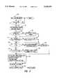
- FIG. 2is a software flow diagram of the power-up sequence carried out by the microcontroller located at the central site;
- FIG. 3is a software flow diagram of the main routine carried out by the microcontroller means at the local site following a successful power-up sequence
- FIG. 4is a software flow diagram illustrating the features of the program incorporated into the microcontroller means at the remote site.
- FIG. 5illustrates a preferred message format and the significance of the message header bits thereof.
- FIG. 1there is illustrated by means of a block diagram, the components of the optically-powered, fiber-optical data-link in accordance with the present invention.
- the systemis indicated generally by numeral 10 and is adapted to interface a local system control module 12 to a remotely located process variable transmitter.
- Module 12represents a device or system whose operating parameters are to be controlled as a function of information provided to it by the remotely located process variable sensor/transmitter module 14.
- process variableis meant to include one or more of such things as pressure, temperature, flow, motion, density or any other parameter whose value is of importance in the carrying out of some process by the system control module 12.
- the optically-powered, fiber-optic data-link 10includes a light source and data processing module 16 and a remote interface module 18 that are coupled together by way of first and second optical fibers 20 and 22. While two discrete optical fibers are shown in FIG. 1, it is possible to couple a single optical fiber between the respective input and output terminals using conventional fiber-optical coupler devices, and limitation to a system having two discrete optical fibers is not to be inferred.
- optical fibersare represented by dashed heavy lines. Customer-supplied electrical connections are shown in solid heavy line while internal electrical connections for the interface modules 16 and 18 are shown in a thin solid line representation.
- the light source module 16it is seen to comprise a first microcontroller means 24 that is adapted to receive digital information provided to it over the second optical fiber 22 to a first input terminal 25 to which a photo-diode receiver 26 is connected.
- the photo-diode receiver 26comprises an optical-to-electrical transducer and pulse shaper for supplying digitally encoded status information to the microcontroller means 24.
- the microcontroller means 24provides a first output over line 28 to an analog signal transmitter 30.
- the output from the analog transmitter 30is applied as an input to analog/digital I/O circuit 32.
- This analog information on output 39may, for example, be an industry standard current signal in the range of from 4 to 20 mA.
- the current amplitude of this signalthat is indicative of the process variable measurement provided by the sensor/transmitter module 14.
- 4 to 20 mA control loopsare conventionally used in a wide variety of process control systems.
- the system of the present inventionis compatible with that conventional scheme.
- the analog signal on line 39may be a voltage level rather than a 4 to 20 mA current signal.
- the system of the present inventionis also compatible with the exchange of information in a digital rather than analog transmission scheme.
- the microcontroller 24also is capable of outputting a digital value over line 34 to a digital transmitter 36, which is also coupled, via the analog/digital I/O interface module 32 and data link 38, to the system being controlled 12.
- the system being controlled 12may also communicate back to the transmitter device 14.
- digital or analog informationis fed over the customer-supplied electrical link 38 to the digital receiver circuit 40, via the analog/digital I/O module 32.
- the digital receiver 40provides its output to the microcontroller 24 where the message is properly formatted and applied to a light source modulator circuit 42, whereby frequency shift keying or other modulation techniques can be used to superimpose digital information onto the analog light level delivered to the optical fiber 20 at a first output terminal 44 of the light source module 16. Because the average value of the digital signal is zero, the superposition of the digital signal does not alter the analog information being transmitted.
- the microcontroller 24also operates to control the amplitude of the optical energy by controlling the amount of electrical power (current) delivered from the light source power supply 46 to the light source modulator 42.
- the remote interface module 18includes a second input terminal 48 to which the optical fiber 20 connects.
- This second input terminalreceives the light energy delivered over the optical fiber 20 and converts that energy into an electrical signal proportional thereto, via a photo-diode power converter circuit 50.
- the information contentwhen sent in digital form, is detected by a digital receiver circuit 52 and applied as an input to a second microcontroller means 54.
- the microcontroller means 54also receives signals defining the state of a process variable (PV) sensed by the remote process variable transmitter 14, via the customer-supplied electrical link 56.
- PVprocess variable
- the information transmitted over the electrical connection 56may be either in digital or analog form depending upon the type of PV sensor/transmitter 14 employed.
- the information from the PV sensor/transmitter 14is fed into the analog and digital transceiver 58, with the digital component being fed through the digital interface circuit 60 to the remote microcontroller 54 and the analog component being delivered through the analog interface circuit 62 to the remote microcontroller 54.
- An A/D converter(not shown) located either in interface circuit 62 or forming part of the microcontroller 54 converts the analog output from PV transmitter to a digital quantity.
- the remote microcontrolleris operative to transmit status information and messages, via a LED transmitter circuit 64, to a second output terminal 66 to which the optical fiber 22 is connected.
- the output from the photo-diode power converter 50is applied to a power supply converter 68 which is adapted to supply electrical energy to the remote process variable transmitter 14.
- the power supply converter 68is controlled by the remote microcontroller 54 in a fashion to be described in greater detail hereinbelow.
- the digital modulation carried by the optical signal being transmitted via optical fiber 20is received via the photo-diode power converter 50 and the digital receiver 52 where it is then supplied as an input to the microprocessor forming a part of the remote microcontroller 54.
- the digital information to be transmitted to the remote PV sensor/transmitter device 14is fed out of the remote microcontroller to a digital transmitter circuit 70 whose output feeds into the analog/digital combiner network 58 and, thence, over the customer-supplied electrical line 56 to the PV sensor/transmitter device 14.
- the local light source module 16the laser, LED or other light source output optical power from the light source modulator 42 is controlled to provide eye safety through a special power-up sequence and maximum laser life by operating at the lowest possible optical output power capable of providing adequate electrical power at the remote end for powering the electronic circuitry in the remote module 18 as well as in the PV sensor/transmitter device 14.
- the light source eye safety featureis achieved by controlling the light source start-up time. Optical energy being transmitted out from the output terminal 44 and over the optical fiber 20 is ramped up from a low value.
- the very low-power optical outputwhen received by the photo-diode power converter 50 and, ultimately, the remote microcontroller 54, effectively "wakes-up” the remote microcontroller and causes it to output a digital status word, via LED transmitter 64, over the optical fiber 22 to the photo-diode receiver 26. During this time, the power output on line 74 to the PV transmitter 14 is disabled.
- the photo-diode receiver 26provides an appropriate input to the light source microcontroller 24 will that microcontroller instruct the light source power supply 46 to increase the optical power output from the light source modulator 42.
- the light source microcontroller 24would not have received the appropriate status message and, as a result, the light source modulator 42 would not become powered-up to the point where the optical energy being transmitted would be sufficient to cause eye damage.
- continuous checksare made at periodic intervals to insure that the remote interface module 18 is responding regularly with status data indicating that operating conditions are normal.
- the light source module 16 at the local sitealso functions to provide analog signal reconversion. That is to say, the analog signal being transmitted from the PV transmitter device 14 is reconverted back to an analog voltage or a 4-20 mA current loop and fed over customer-supplied electrical line 39 to the control system 12.
- the remote interface module 18functions to measure and digitize the output from the photo-diode power converter 50, the power supply voltage to the transmitter 14, and the analog voltage from the transmitter. It then communicates status information as to how well the remote module 18 is functioning. More particularly, it carries out the power-up mode described above to insure eye safety and provided that all optical data-links are properly connected, assumes a normal operating mode in which all the pertinent data is sent to the local interface module 16 at predetermined data transmission rates. In the event of an error condition, such as a short circuit of the output current to the transmitter, a broken fiber in the power fiber link 20, etc., an error flag is sent back to the local interface module 16 to activate indicator lights in a manner yet to be described and appropriate corrective action can be initiated.
- an error conditionsuch as a short circuit of the output current to the transmitter, a broken fiber in the power fiber link 20, etc.
- the remote interface module 18also functions to optimize the power converter 68.
- the purpose of thisis to monitor the photo-converter operating point to insure that it remains in the most efficient optical-to-electrical conversion segment of its current/voltage curve. This is done by periodically creating an open circuit in the output power being delivered to the sensor/transmitter 14 and then heavily loading the photo-diode in the photo-diode power converter 50 while recording the photo-diode voltages in the memory of the microprocessor used in the remote microcontroller 54.
- the datais used to control the duty cycle of the D.C. to D.C. power converter 18 so as to optimize the photo-converter operating point.
- the output power to it from the power supply converter 68is switched on. If the stored energy is insufficient, the power is removed from the transmitter and an alarm condition flag is sent, via the data-link 58, 60 or 62, 64, and the optical fiber 22 to the photo-diode receiver 26.
- FIGS. 2, 3 and 4which define the software programs executed by the microprocessors in the controllers 24 and 54, an explanation will be given as to how control is exerted over the hardware components by the respective local and remote microprocessor in the microcontrollers 24 and 25.
- the flow chartsare written in sufficient detail so as to permit persons skilled in the art to write source code/object code for the selected microprocessors involved.
- the microprocessor-based controller 24When the system is turned on, the microprocessor-based controller 24 "wakes-up" and undergoes an initialization sequence as represented by block 80. Assuming that the light source in question is a laser or laser diode, the voltage to the laser is first set to zero. Also, the analog output from the analog transmitter 30 is also set to zero and other housekeeping steps are executed to set up the microprocessors' ports, initiate the system timer at 1/60 Hz and to read the status of certain jumpers or dip switches defining a set of factory-programmed instructions that identify exactly the type of D/A conversion that is involved and the type of PV sensor/transmitter that is being used.
- the jumpers or dip switchesmay establish whether it is a voltage signal from the remote transmitter to a 4-20 mA current loop on the local end or a particular combination of actual analog information that is to be transferred across the interface.
- the communications loopis operating at a 60 Hz update rate, so that every 1/60th of a second the remote end sends all of its status and data information to the local end, those skilled in the art can appreciate that update rates other than 60 Hz can also be employed.
- the microcontroller 24allows the light source power supply 46 to ramp-up the laser voltage, with the voltage being incremented every 1/60th of a second. During each such period, a test is made to see whether a signal has arrived from the remote end, thereby indicating that the remote end is also in the process of waking up because it is now receiving power, albeit at a low level, over the optical data-link 20 as already described. A test is made at decision block 84 as to whether a signal has arrived from the remote interface module 18. If it has, the timer is reset, as indicated by block 86, as is a cycle counter. Then, control exits to the main sequence illustrated in the flow diagram of FIG. 3.
- a baselineis established for the 1/60th of a second period. After that, at succeeding 1/60th of a second intervals, the local microcontroller should be expecting another message from the remote interface module 18. If none is received, an error indication is provided, via indicator lights 174 and 176 (FIG. 1).
- the microcontroller 24counts up another 1/60th of a second on its own and then checks to see if a remote signal has arrived yet. This is the function of the decision block 90. Control loops back over path 92 until such time as the test at decision block 90 shows that the elapsed time has exceeded one cycle. At that point, a test is made at block 94 to see if so much time has elapsed that a predetermined maximum count has been reached.
- the "max count value"is a programmable quantity.
- the voltage to the laser light sourceis incremented by one step at operation block 100.
- Decision block 102tests whether the laser voltage is greater than or equal to the full rated power value for the laser.
- FFis the hexadecimal representation equal to 256 (decimal) which comprises one full 8-bit word in machine code. If the laser voltage is greater than full power, it is indicative that the laser is being over-powered and this constitutes another error condition involving manual intervention as represented by operation block 104. If, on the other hand, the laser voltage is not greater than its full rated value, control exits the decision block 102, via path 106, which leads to the input of the decision block 84.
- a messageconsists of six 8-bit bytes where the sixth byte contains the numeric sum of all the other bytes in the message as a check sum for error detection purposes.
- the use of check sums to indicate errors in the transmission of a messageis a well established technique.
- FIG. 5illustrates the format of a typical message and the interpretation of the bits of the 8-bit header byte.
- bit B 0 in the headeris set, it is indicative that the system is configured to allow simultaneous transmission of both digital information and analog information using the so-called HART protocol.
- the B 1 bitis a transmitter voltage alarm which is set if there is an emergency condition. For example, if the leads on the transmitter should be inadvertently shorted out, header bit B 1 will be set and, in this fashion, the local interface unit 16 is advised so that corrective action can be taken.
- Header bit B 2is the photo-diode voltage alarm bit that checks on the status of the photo-diode voltage generated by the photo-diode in block 50 when illuminated by light transmitted over optical fiber 20. This voltage needs to be in a very narrow voltage range for insuring optimum power transfer efficiency. When bit B 2 is set, it is indicative that the photo-diode voltage is not within the desired range.
- a measurement of the photo-diode open circuit voltageis taken and if header bit B 3 is set, it is indicative that the message bits following provide information as to that measured open circuit voltage value.
- Bit B 4is a watchdog timer (WDT) bit which is employed in a conventional fashion to indicate that for some reason, the microprocessor may be involved in an endless loop.
- WDTwatchdog timer
- B 4is set to indicate to the local module 16 that some type of logical error condition exists in the microprocessor implementing the remote microcontroller 54.
- Header bit B 5is set when the voltage to the transmitter 14 has been turned on.
- Header bit B 6is a request from the remote microcontroller 54 that the laser interface module 16 apply full-rated laser power to the light source. Finally, bit B7 when set indicates that the remote interface module 18 is in a wake-up sequence.
- the message header bits and the accompanying data packetcomprising bytes 2, 3 and 5 of the message are read. See block 112.
- the test at decision block 114causes the microprocessor in the microcontroller 24 to check bit B7 of the header and if it is set, the microprocessor in the microcontroller 24 causes the light source power supply 46 to increase the power delivered to the laser (block 116).
- a testis then made at decision block 118 to determine whether header bit B 6 is set representing a command to shift the laser power to its full-on value.
- the microcontroller 24responds by setting the laser voltage to its rated full-power value (block 120).
- the test at decision block 122checks bit B 3 of the message header. If that bit had been set, then certain special photo-diode information is being sent back from the remote interface module for a special processing by the light source interface module 16. For example, the light source interface module can check to determine whether the photo-diode is actually operating at its proper operating point (block 124). Thus, if bit B 3 is set, and it is determined that the operating point of the photo-diode in the photo-diode power converter 50 is not optimum, a flag or an alarm is set (block 126) so that the alarm condition can be transmitted on to the microcontroller 24 and used to energize the indicator lamps 174 and 176 for diagnostic purposes.
- Decision block 128tests whether there has been a photo-diode voltage or transmitter voltage alarm that needs to be serviced. Appropriate remedial action must then be taken as represented by block 130.
- a proportional integral control algorithmis used. More particularly, an error voltage is set to equal the present transmitter voltage minus the transmitter voltage set-point. The summing operation of error terms forms the integral term of the control algorithm. The net result is that the laser voltage is set to some constant K p times the error voltage plus an integral constant K i times the integral term.
- the laser currentis sent out to a digital-to-analog converter (not shown) forming part of microcontroller 24 which directly controls the amount of current energizing the laser. (See operation blocks 134 and 136.) Control then loops back to the input of block 108 where the system awaits receipt of the next message.
- FIG. 4is a software flow diagram for the program executed by the microprocessor of the remote microcontroller 54 shown in FIG. 1.
- the photo-diode power converter 50detects that optical power is being ramped up and applied, via optical fiber 20, the photo-diode voltage begins to increase and the microprocessor wakes-up.
- This operationis represented by the power-on reset box 140 in FIG. 4.
- the power-on reset operationinitiates a number of housekeeping operations.
- the input/output ports of the microprocessor in the microcontroller 54needs to be initialized and an output power switch controlling the transmitter voltage must be turned off so that all available power is provided to the microcontroller and its associated electronics.
- an analog-to-digital converter in circuit 58is turned off to also conserve power.
- the cycle timerthat measures the 16.66 millisecond intervals is initiated.
- the microprocessor 54then proceeds to send a status and wake-up message to the local light source interface, via optical fiber 22, as previously described. See block 144. This apprises the microcontroller 24 at the local site that the optical fibers are intact, at which point the laser or LED light source 42 is instructed to progress to its full power output.
- the voltage control switch (not shown) for the transmitteris then turned on, providing the PV sensor/transmitter 14 with the necessary electrical power to allow it to function.
- a testis made at decision 148 to determine whether the power being supplied to the PV sensor/transmitter 14 is up to a predetermined threshold. If not, control loops back to block 150 to wait one additional cycle before repeating steps 146 and 148. If the sensor/transmitter voltage is up to its threshold value, a test is made at block 152 to determine whether the photo-diode voltage from the photo-diode power converter circuit 50 is at its desired threshold value. Again, if it is not, control returns to block 150 and after a further cycle has elapsed, steps 146, 148 and 152 are repeated.
- the on-chip A/D convertermeasures the transmitter voltage and the photo-diode voltage and digitizes those two parameters prior to transmission of the messages in a digital format to the local light source module 16.
- the watchdog timeris cleared and after each 60th cycle (one second intervals) the photo-diode current or some other photo-diode parameter is measured and transmitted back with the next message burst to the local light source interface module.
- a testis made at decision block 158 to determine whether the photo-diode output voltage is exceeding its threshold, which is a programmed setpoint that is generally set at a couple of volts below its desired operating point. If the photo-diode voltage falls below that value, it represents an error condition and an alarm is sent to the local light control module (block 160) and, in addition, the switch controlling the application of voltage to the transmitter 14 is opened. If, on the other hand, the photo-diode voltage is above its threshold, control exits to block 162 and a closed loop photo-diode controller algorithm is executed. This algorithm measures the current photo-diode voltage and compares it against the open circuit photo-diode voltage.
- the operating photo-diode voltagemay typically be several hundred millivolts below the open circuit voltage value in order to get maximum power out of the photo-diode.
- the closed loop photo-diode control algorithm 162essentially sets the duty cycle of a DC to DC inductive switching converter contained in remote interface module 18 to either limit or increase the amount of current supplied to the photo-diode to bring its output voltage to its desired operating point.
- a predetermined time delaye.g., 0.4 milliseconds
- the analog output from the transmitteris then converted to a digital representation thereof after which the A/D converter can again be turned off to conserve power (block 166).
- the remote microcontroller 54controls the LED transmitter 64 to transmit all six bytes of the message back to the local light source interface (block 168) and then control exits, via path 170, where operation suspends until the next cycle is initiated by the timer circuitry (block 172). This reinitiates the main remote microprocessor control loop.
- LEDs 174 and 176LEDs 174 and 176
- LED 174 and 176LEDs 174 and 176
- FIG. 1When the system is working properly, i.e., no transmitter fault or discontinuous optical loop, LED 174 will be off and LED 176 will be on. Had the optical loop failed, only LED 174 would be illuminated. If it were the PV transmitter that had failed, LEDs 174 and 176 will both be on. In the event of a power failure, both LEDs will be off. Finally, if system maintenance is needed, say, to replace the photo diode 50 or the laser driven by light source modulator 42, LED 174 will be off and LED 176 will intermittently flash.
Landscapes
- Physics & Mathematics (AREA)
- Electromagnetism (AREA)
- Engineering & Computer Science (AREA)
- Computer Networks & Wireless Communication (AREA)
- Signal Processing (AREA)
- Optical Communication System (AREA)
- Selective Calling Equipment (AREA)
- Arrangements For Transmission Of Measured Signals (AREA)
Abstract
Description
Claims (23)
Priority Applications (7)
| Application Number | Priority Date | Filing Date | Title |
|---|---|---|---|
| US08/322,584US5528409A (en) | 1994-10-13 | 1994-10-13 | Fiber-optic interface system |
| PCT/US1995/012962WO1996012357A1 (en) | 1994-10-13 | 1995-10-03 | Fiber-optic interface system |
| CA002201894ACA2201894C (en) | 1994-10-13 | 1995-10-03 | Fiber-optic interface system |
| DE69520371TDE69520371T2 (en) | 1994-10-13 | 1995-10-03 | FIBER OPTICAL INTERFACE SYSTEM |
| JP8513346AJPH10507602A (en) | 1994-10-13 | 1995-10-03 | Fiber optic interface system |
| EP95939505AEP0801854B1 (en) | 1994-10-13 | 1995-10-03 | Fiber-optic interface system |
| BR9509304ABR9509304A (en) | 1994-10-13 | 1995-10-03 | Fiber optic interface system |
Applications Claiming Priority (1)
| Application Number | Priority Date | Filing Date | Title |
|---|---|---|---|
| US08/322,584US5528409A (en) | 1994-10-13 | 1994-10-13 | Fiber-optic interface system |
Publications (1)
| Publication Number | Publication Date |
|---|---|
| US5528409Atrue US5528409A (en) | 1996-06-18 |
Family
ID=23255527
Family Applications (1)
| Application Number | Title | Priority Date | Filing Date |
|---|---|---|---|
| US08/322,584Expired - Fee RelatedUS5528409A (en) | 1994-10-13 | 1994-10-13 | Fiber-optic interface system |
Country Status (7)
| Country | Link |
|---|---|
| US (1) | US5528409A (en) |
| EP (1) | EP0801854B1 (en) |
| JP (1) | JPH10507602A (en) |
| BR (1) | BR9509304A (en) |
| CA (1) | CA2201894C (en) |
| DE (1) | DE69520371T2 (en) |
| WO (1) | WO1996012357A1 (en) |
Cited By (116)
| Publication number | Priority date | Publication date | Assignee | Title |
|---|---|---|---|---|
| US5715077A (en)* | 1994-09-19 | 1998-02-03 | Vlsi Technology, Inc. | Multi-mode infrared input/output interface |
| US5739938A (en)* | 1996-09-10 | 1998-04-14 | Northrop Grumman Corporation | Optically-powered directly-modulated fiber optic link |
| US5764395A (en)* | 1995-06-14 | 1998-06-09 | Nec Corporation | Infrared spatial communication system capable of reducing a processing amount of data communication devices during communication |
| US5771114A (en)* | 1995-09-29 | 1998-06-23 | Rosemount Inc. | Optical interface with safety shutdown |
| US5822200A (en)* | 1997-04-21 | 1998-10-13 | Nt International, Inc. | Low level, high efficiency DC/DC converter |
| US5987554A (en)* | 1997-05-13 | 1999-11-16 | Micron Electronics, Inc. | Method of controlling the transfer of information across an interface between two buses |
| US6009541A (en)* | 1997-10-01 | 1999-12-28 | Micron Electronics, Inc. | Apparatus for performing an extensive diagnostic test in conjunction with a bios test routine |
| US6035420A (en)* | 1997-10-01 | 2000-03-07 | Micron Electronics, Inc. | Method of performing an extensive diagnostic test in conjunction with a bios test routine |
| US6065053A (en)* | 1997-10-01 | 2000-05-16 | Micron Electronics, Inc. | System for resetting a server |
| US6073255A (en)* | 1997-05-13 | 2000-06-06 | Micron Electronics, Inc. | Method of reading system log |
| US6088816A (en)* | 1997-10-01 | 2000-07-11 | Micron Electronics, Inc. | Method of displaying system status |
| US6122746A (en)* | 1997-05-13 | 2000-09-19 | Micron Electronics, Inc. | System for powering up and powering down a server |
| US6122758A (en)* | 1997-05-13 | 2000-09-19 | Micron Electronics, Inc. | System for mapping environmental resources to memory for program access |
| US6134668A (en)* | 1997-05-13 | 2000-10-17 | Micron Electronics, Inc. | Method of selective independent powering of portion of computer system through remote interface from remote interface power supply |
| US6134673A (en)* | 1997-05-13 | 2000-10-17 | Micron Electronics, Inc. | Method for clustering software applications |
| US6138250A (en)* | 1997-05-13 | 2000-10-24 | Micron Electronics, Inc. | System for reading system log |
| US6138179A (en)* | 1997-10-01 | 2000-10-24 | Micron Electronics, Inc. | System for automatically partitioning and formatting a primary hard disk for installing software in which selection of extended partition size is not related to size of hard disk |
| US6145098A (en)* | 1997-05-13 | 2000-11-07 | Micron Electronics, Inc. | System for displaying system status |
| US6148355A (en)* | 1997-05-13 | 2000-11-14 | Micron Electronics, Inc. | Configuration management method for hot adding and hot replacing devices |
| US6154835A (en)* | 1997-10-01 | 2000-11-28 | Micron Electronics, Inc. | Method for automatically configuring and formatting a computer system and installing software |
| US6163849A (en)* | 1997-05-13 | 2000-12-19 | Micron Electronics, Inc. | Method of powering up or powering down a server to a maintenance state |
| US6163825A (en)* | 1997-05-13 | 2000-12-19 | Micron Electronics, Inc. | Method for hot adding a network adapter by identifying and executing the adapter driver based upon the logical board number of the network adapter |
| US6163853A (en)* | 1997-05-13 | 2000-12-19 | Micron Electronics, Inc. | Method for communicating a software-generated pulse waveform between two servers in a network |
| US6170067B1 (en) | 1997-05-13 | 2001-01-02 | Micron Technology, Inc. | System for automatically reporting a system failure in a server |
| US6170028B1 (en) | 1997-05-13 | 2001-01-02 | Micron Electronics, Inc. | Method for hot swapping a programmable network adapter by using a programmable processor to selectively disabling and enabling power thereto upon receiving respective control signals |
| US6173346B1 (en) | 1997-05-13 | 2001-01-09 | Micron Electronics, Inc. | Method for hot swapping a programmable storage adapter using a programmable processor for selectively enabling or disabling power to adapter slot in response to respective request signals |
| US6175490B1 (en) | 1997-10-01 | 2001-01-16 | Micron Electronics, Inc. | Fault tolerant computer system |
| US6182180B1 (en) | 1997-05-13 | 2001-01-30 | Micron Electronics, Inc. | Apparatus for interfacing buses |
| US6179486B1 (en) | 1997-05-13 | 2001-01-30 | Micron Electronics, Inc. | Method for hot add of a mass storage adapter on a system including a dynamically loaded adapter driver |
| US6189109B1 (en) | 1997-05-13 | 2001-02-13 | Micron Electronics, Inc. | Method of remote access and control of environmental conditions |
| US6192434B1 (en) | 1997-05-13 | 2001-02-20 | Micron Electronics, Inc | System for hot swapping a programmable adapter by using a programmable processor to selectively disabling and enabling power thereto upon receiving respective control signals |
| US6195717B1 (en) | 1997-05-13 | 2001-02-27 | Micron Electronics, Inc. | Method of expanding bus loading capacity |
| US6199173B1 (en) | 1997-10-01 | 2001-03-06 | Micron Electronics, Inc. | Method for mapping environmental resources to memory for program access |
| US6202160B1 (en) | 1997-05-13 | 2001-03-13 | Micron Electronics, Inc. | System for independent powering of a computer system |
| US6202111B1 (en) | 1997-05-13 | 2001-03-13 | Micron Electronics, Inc. | Method for the hot add of a network adapter on a system including a statically loaded adapter driver |
| US6205503B1 (en) | 1998-07-17 | 2001-03-20 | Mallikarjunan Mahalingam | Method for the hot swap and add of input/output platforms and devices |
| US6212585B1 (en) | 1997-10-01 | 2001-04-03 | Micron Electronics, Inc. | Method of automatically configuring a server after hot add of a device |
| US6219734B1 (en) | 1997-05-13 | 2001-04-17 | Micron Electronics, Inc. | Method for the hot add of a mass storage adapter on a system including a statically loaded adapter driver |
| US6223234B1 (en) | 1998-07-17 | 2001-04-24 | Micron Electronics, Inc. | Apparatus for the hot swap and add of input/output platforms and devices |
| US6233285B1 (en) | 1997-12-23 | 2001-05-15 | Honeywell International Inc. | Intrinsically safe cable drive circuit |
| US6243773B1 (en) | 1997-05-13 | 2001-06-05 | Micron Electronics, Inc. | Configuration management system for hot adding and hot replacing devices |
| US6243838B1 (en) | 1997-05-13 | 2001-06-05 | Micron Electronics, Inc. | Method for automatically reporting a system failure in a server |
| US6247080B1 (en) | 1997-05-13 | 2001-06-12 | Micron Electronics, Inc. | Method for the hot add of devices |
| US6247079B1 (en)* | 1997-05-13 | 2001-06-12 | Micron Electronics, Inc | Apparatus for computer implemented hot-swap and hot-add |
| US6247898B1 (en) | 1997-05-13 | 2001-06-19 | Micron Electronics, Inc. | Computer fan speed control system |
| US6249885B1 (en) | 1997-05-13 | 2001-06-19 | Karl S. Johnson | Method for managing environmental conditions of a distributed processor system |
| US6249828B1 (en) | 1997-05-13 | 2001-06-19 | Micron Electronics, Inc. | Method for the hot swap of a mass storage adapter on a system including a statically loaded adapter driver |
| US6249834B1 (en) | 1997-05-13 | 2001-06-19 | Micron Technology, Inc. | System for expanding PCI bus loading capacity |
| US6253334B1 (en) | 1997-05-13 | 2001-06-26 | Micron Electronics, Inc. | Three bus server architecture with a legacy PCI bus and mirrored I/O PCI buses |
| US6263387B1 (en) | 1997-10-01 | 2001-07-17 | Micron Electronics, Inc. | System for automatically configuring a server after hot add of a device |
| US6269417B1 (en) | 1997-05-13 | 2001-07-31 | Micron Technology, Inc. | Method for determining and displaying the physical slot number of an expansion bus device |
| US6282673B1 (en) | 1997-05-13 | 2001-08-28 | Micron Technology, Inc. | Method of recording information system events |
| US6288813B1 (en)* | 1998-03-25 | 2001-09-11 | The United States Of America As Represented By The Administrator Of The National Aeronautics And Space Administration | Apparatus and method for effecting data transfer between data systems |
| US6292905B1 (en) | 1997-05-13 | 2001-09-18 | Micron Technology, Inc. | Method for providing a fault tolerant network using distributed server processes to remap clustered network resources to other servers during server failure |
| WO2001073962A1 (en)* | 2000-03-24 | 2001-10-04 | Northrop Grumman Corporation | Infrared communication scheme with electrical interface for embedded systems |
| US6304929B1 (en) | 1997-05-13 | 2001-10-16 | Micron Electronics, Inc. | Method for hot swapping a programmable adapter by using a programmable processor to selectively disabling and enabling power thereto upon receiving respective control signals |
| US6330690B1 (en) | 1997-05-13 | 2001-12-11 | Micron Electronics, Inc. | Method of resetting a server |
| WO2001051970A3 (en)* | 2000-01-12 | 2001-12-20 | Ciena Corp | System and method for detecting imperfect connections in optical systems |
| US6338150B1 (en) | 1997-05-13 | 2002-01-08 | Micron Technology, Inc. | Diagnostic and managing distributed processor system |
| US20020060824A1 (en)* | 2000-07-18 | 2002-05-23 | Kang-Yih Liou | Optical transponders and transceivers |
| US6418492B1 (en) | 1997-05-13 | 2002-07-09 | Micron Electronics | Method for computer implemented hot-swap and hot-add |
| US6499073B1 (en) | 1997-05-13 | 2002-12-24 | Micron Electronics, Inc. | System using programmable processor for selectively enabling or disabling power to adapter in response to respective request signals |
| US20030020979A1 (en)* | 2001-07-30 | 2003-01-30 | Bell John Arnold | Remote optical transmitter output power control |
| US6526333B1 (en) | 1997-05-13 | 2003-02-25 | Micron Technology, Inc. | Computer fan speed control system method |
| US6550338B1 (en) | 2000-07-07 | 2003-04-22 | Ardishir Rashidi | Pressure sensing device |
| US20030075698A1 (en)* | 2001-10-19 | 2003-04-24 | Visteon Global Technologies, Inc. | LCC-based fluid-level detection sensor |
| FR2831344A1 (en)* | 2001-10-19 | 2003-04-25 | Visteon Global Tech Inc | LIGHT COMMUNICATION CONDUIT POWER SUPPLY DISTRIBUTION SYSTEM |
| US20030090161A1 (en)* | 2001-10-19 | 2003-05-15 | Marlow C. Allen | Light communication channel-based electronics power distribution system |
| US20030095675A1 (en)* | 2001-10-19 | 2003-05-22 | Marlow C. Allen | Light communication channel-based voice-activated control system and method for implementing thereof |
| US20030138195A1 (en)* | 2002-01-23 | 2003-07-24 | Shyh-Lin Tsao | Wavelength to optical power converter and method for converting wavelength into optical power |
| US6701453B2 (en) | 1997-05-13 | 2004-03-02 | Micron Technology, Inc. | System for clustering software applications |
| US6742069B2 (en) | 1997-05-13 | 2004-05-25 | Micron Technology, Inc. | Method of providing an interface to a plurality of peripheral devices using bus adapter chips |
| WO2004072662A2 (en) | 2003-02-12 | 2004-08-26 | IAD Gesellschaft für Informatik, Automatisierung und Datenverarbeitung mbH | Measuring system comprising an intelligent sensor head and having a reduced power consumption for medium-voltage or high-voltage systems or in mining, and method therefor |
| US20050105913A1 (en)* | 2003-11-14 | 2005-05-19 | Fuji Xerox Co., Ltd. | Signal transmission device |
| US20060062515A1 (en)* | 2004-09-22 | 2006-03-23 | Kamran Mahbobi | Apparatus and method for transmitting electrical power through a transparent or substantially transparent medium |
| US20060098270A1 (en)* | 2004-11-05 | 2006-05-11 | Fujitsu Limited | Optical output power automatic attenuation circuit for optical communication apparatus |
| US20060146892A1 (en)* | 2004-12-30 | 2006-07-06 | Imra America, Inc. | Method and apparatus for obtaining and maintaining mode-locking in fiber laser systems |
| US20070122156A1 (en)* | 2005-11-28 | 2007-05-31 | Tongqing Wang | Apparatus, system, and method for interconnecting electrical and electronic signals |
| US20080085126A1 (en)* | 2006-10-09 | 2008-04-10 | Verizon Services Corp. | Optical Signal Shutoff Mechanism and Associated System |
| US7359647B1 (en)* | 2004-04-06 | 2008-04-15 | Nortel Networks, Ltd. | Method and apparatus for transmitting and receiving power over optical fiber |
| US20090016715A1 (en)* | 2007-07-11 | 2009-01-15 | James Furey | Power over optical fiber system |
| US20090103925A1 (en)* | 2005-09-27 | 2009-04-23 | Ortal Alpert | Directional Light Transmitter and Receiver |
| US20090200450A1 (en)* | 2008-02-12 | 2009-08-13 | Rintaro Nomura | Burst light receiving power monitor circuit, method, and program |
| EP2112774A1 (en)* | 2008-04-22 | 2009-10-28 | ABB Schweiz AG | Output control system and communications method |
| US20100320362A1 (en)* | 2008-01-03 | 2010-12-23 | Ortal Alpert | Wireless laser power transmitter |
| US20110038639A1 (en)* | 2009-08-14 | 2011-02-17 | International Business Machines Corporation | Power-up of device via optical serial interface |
| US7956733B1 (en) | 2008-09-23 | 2011-06-07 | The United States Of America As Represented By The Secretary Of The Navy | Optical fiber sensor for quantitative monitoring of deflection from high-speed launcher operation conditions |
| US20110280586A1 (en)* | 2010-05-11 | 2011-11-17 | Searete Llc, A Limited Liability Corporation Of The State Of Delaware | Optical power transmission packeting systems and methods |
| US20120155886A1 (en)* | 2010-12-20 | 2012-06-21 | Hon Hai Precision Industry Co., Ltd. | Optical fiber connector |
| US8358893B1 (en)* | 2010-01-14 | 2013-01-22 | Sandia Corporation | Photonic-powered cable assembly |
| US20140016945A1 (en)* | 2012-07-16 | 2014-01-16 | Yang Pan | Information System Including a Card and a Card Reader Connected Optically |
| WO2014072891A1 (en)* | 2012-11-08 | 2014-05-15 | Koninklijke Philips N.V. | An optical probe system |
| WO2014097215A1 (en)* | 2012-12-19 | 2014-06-26 | Zodiac Aerotechnics | Optically-powered sensor systems, suitable for deployment on-board aircraft |
| US8842995B2 (en) | 2010-05-11 | 2014-09-23 | The Invention Science Fund I, Llc | Optical power transmission systems and methods |
| US20140285033A1 (en)* | 2013-03-20 | 2014-09-25 | Nokia Corporation | Method, apparatus, and computer program product for powering electronics in smart covers |
| US8971722B2 (en) | 2010-05-11 | 2015-03-03 | The Invention Science Fund I, Llc | Optical power distribution device and method |
| WO2016046006A1 (en)* | 2014-09-22 | 2016-03-31 | Technische Universität Dresden | System and method for controlled energy transmission |
| US9325206B2 (en) | 2010-05-11 | 2016-04-26 | Deep Science, Llc | Optical power transmission system and method having counter-propagating control signal |
| US9369008B2 (en) | 2013-03-20 | 2016-06-14 | Nokia Technologies Oy | Method, apparatus, and computer program product for powering electronic devices |
| US20170176235A1 (en)* | 2015-12-17 | 2017-06-22 | Simmonds Precision Products, Inc. | Systems and methods for liquid level detection |
| US20170272157A1 (en)* | 2016-03-15 | 2017-09-21 | Simmonds Precision Products, Inc. | Optically interfaced remote data concentrator |
| US9941965B2 (en)* | 2015-07-15 | 2018-04-10 | Flextronics Ap, Llc | Laser and optical charging and communications device and method of use |
| US20180129186A1 (en)* | 2015-05-05 | 2018-05-10 | Areva Np | Mosaic module for a control panel of a power plant, control panel, and system comprising a control panel and a power generating unit |
| US20180323880A1 (en)* | 2013-03-12 | 2018-11-08 | Commscope Technologies Llc | Optically powered media converter |
| US10313026B2 (en)* | 2017-06-27 | 2019-06-04 | Rolls-Royce North American Technologies, Inc. | Power and communications over fiber optic cabling |
| US10608830B2 (en) | 2017-02-06 | 2020-03-31 | Mh Gopower Company Limited | Power over fiber enabled sensor system |
| CN112311474A (en)* | 2019-08-02 | 2021-02-02 | 京瓷株式会社 | Optical fiber power supply system and power supply side data communication device of optical fiber power supply system |
| EP3772194A1 (en)* | 2019-08-02 | 2021-02-03 | Kyocera Corporation | Power over fiber system |
| US20210226708A1 (en)* | 2020-01-17 | 2021-07-22 | The Boeing Company | Drone network and method of operating |
| WO2021189106A1 (en)* | 2020-03-24 | 2021-09-30 | Newsouth Innovations Pty Limited | Optically powered sensing system and method for hazardous environments |
| US20210409116A1 (en)* | 2020-06-30 | 2021-12-30 | Rohde & Schwarz Gmbh & Co. Kg | Power-over-fiber system and method for operating a power-over-fiber system |
| US11381321B2 (en) | 2019-07-22 | 2022-07-05 | Kyocera Corporation | Optical power supply system |
| US11387904B2 (en) | 2019-10-24 | 2022-07-12 | Kyocera Corporation | Powered device and power sourcing equipment of optical power supply system, and optical power supply system |
| WO2022186891A1 (en)* | 2021-03-03 | 2022-09-09 | Google Llc | Power adapter that combines power input and communication input |
| US12015449B2 (en)* | 2017-12-29 | 2024-06-18 | Nokia Technologies Oy | Sensing apparatus and system |
| US20240340093A1 (en)* | 2023-04-10 | 2024-10-10 | GM Global Technology Operations LLC | Intra-automobile power and communications via fiber |
Families Citing this family (5)
| Publication number | Priority date | Publication date | Assignee | Title |
|---|---|---|---|---|
| RU2155448C1 (en)* | 1999-10-22 | 2000-08-27 | Александровский Михаил Исаакович | High-speed digital optical signal transmission line |
| RU2155449C1 (en)* | 1999-10-22 | 2000-08-27 | Александровский Михаил Исаакович | Digital optical signal transmission line |
| RU2286647C1 (en)* | 2005-04-12 | 2006-10-27 | Федеральный научно-производственный центр Открытое акционерное общество "Научно-производственное объединение "Марс" (ФНПЦ ОАО "НПО "Марс") | Digital optical signal transmission line |
| JP5264953B2 (en)* | 2011-03-30 | 2013-08-14 | 株式会社フジクラ | Active cable |
| RU2522890C2 (en)* | 2012-07-30 | 2014-07-20 | Российская Федерация, от имени которой выступает Государственная корпорация по атомной энергии "Росатом" (Госкорпорация "Росатом") | Optoelectronic device for analogue signal transmission |
Citations (18)
| Publication number | Priority date | Publication date | Assignee | Title |
|---|---|---|---|---|
| US4346478A (en)* | 1980-12-01 | 1982-08-24 | Siemens Corporation | Fiber optical sensor system, preferably for measuring physical parameters |
| US4345482A (en)* | 1978-11-16 | 1982-08-24 | Asea Aktiebolag | Fiber optical devices for measuring physical phenomenon |
| US4417140A (en)* | 1980-06-23 | 1983-11-22 | Asea Aktiebolag | Fibre optic measuring device with electrically controlled photoluminescence |
| US4434510A (en)* | 1978-03-10 | 1984-02-28 | Lemelson Jerome H | Communication system and method |
| US4434665A (en)* | 1981-01-29 | 1984-03-06 | Asea Aktiebolag | Integrated capacitive transducer |
| US4490606A (en)* | 1982-04-26 | 1984-12-25 | Geosource Inc. | Transducer apparatus utilizing fiber optics for data transmission |
| US4514860A (en)* | 1982-06-02 | 1985-04-30 | Asea Aktiebolag | Fiber optical measuring device for measuring electrical and magnetic quantities by laterally controlled photo-luminescence |
| US4521684A (en)* | 1982-02-22 | 1985-06-04 | The Foxboro Company | Optical measurement system with light-driven vibrating sensor element |
| US4643568A (en)* | 1984-04-05 | 1987-02-17 | Telefonaktiebolaget Lm Ericsson | Method and apparatus for measuring the illuminating power of incident light |
| US4651571A (en)* | 1983-08-04 | 1987-03-24 | Fisher Controls International, Inc. | Strain sensor |
| US4704607A (en)* | 1984-10-25 | 1987-11-03 | Sieger Limited | System for remotely adjusting a parameter of an electrical circuit within an enclosure |
| US4713540A (en)* | 1985-07-16 | 1987-12-15 | The Foxboro Company | Method and apparatus for sensing a measurand |
| US4764244A (en)* | 1985-06-11 | 1988-08-16 | The Foxboro Company | Resonant sensor and method of making same |
| US4820916A (en)* | 1987-05-05 | 1989-04-11 | Simmonds Precision Products | Optically powered sensor system |
| US4856317A (en)* | 1988-05-02 | 1989-08-15 | Fiberoptic Sensor Technologies, Inc. | Vacuum calibration system and method for fiberoptic pressure transducer |
| US4857727A (en)* | 1988-05-12 | 1989-08-15 | Honeywell Inc. | Optically powered remote sensors with timing discrimination |
| US5099144A (en)* | 1988-12-28 | 1992-03-24 | Kabushiki Kaisha Toshiba | Apparatus for optical power transmission and optically powered system |
| US5258868A (en)* | 1990-02-02 | 1993-11-02 | Rosemount Inc. | Optical process variable transmitter |
Family Cites Families (1)
| Publication number | Priority date | Publication date | Assignee | Title |
|---|---|---|---|---|
| US5193201A (en)* | 1990-04-23 | 1993-03-09 | Tymes Laroy | System for converting a received modulated light into both power for the system and image data displayed by the system |
- 1994
- 1994-10-13USUS08/322,584patent/US5528409A/ennot_activeExpired - Fee Related
- 1995
- 1995-10-03DEDE69520371Tpatent/DE69520371T2/ennot_activeExpired - Fee Related
- 1995-10-03EPEP95939505Apatent/EP0801854B1/ennot_activeExpired - Lifetime
- 1995-10-03BRBR9509304Apatent/BR9509304A/ennot_activeApplication Discontinuation
- 1995-10-03CACA002201894Apatent/CA2201894C/ennot_activeExpired - Fee Related
- 1995-10-03WOPCT/US1995/012962patent/WO1996012357A1/enactiveIP Right Grant
- 1995-10-03JPJP8513346Apatent/JPH10507602A/ennot_activeCeased
Patent Citations (18)
| Publication number | Priority date | Publication date | Assignee | Title |
|---|---|---|---|---|
| US4434510A (en)* | 1978-03-10 | 1984-02-28 | Lemelson Jerome H | Communication system and method |
| US4345482A (en)* | 1978-11-16 | 1982-08-24 | Asea Aktiebolag | Fiber optical devices for measuring physical phenomenon |
| US4417140A (en)* | 1980-06-23 | 1983-11-22 | Asea Aktiebolag | Fibre optic measuring device with electrically controlled photoluminescence |
| US4346478A (en)* | 1980-12-01 | 1982-08-24 | Siemens Corporation | Fiber optical sensor system, preferably for measuring physical parameters |
| US4434665A (en)* | 1981-01-29 | 1984-03-06 | Asea Aktiebolag | Integrated capacitive transducer |
| US4521684A (en)* | 1982-02-22 | 1985-06-04 | The Foxboro Company | Optical measurement system with light-driven vibrating sensor element |
| US4490606A (en)* | 1982-04-26 | 1984-12-25 | Geosource Inc. | Transducer apparatus utilizing fiber optics for data transmission |
| US4514860A (en)* | 1982-06-02 | 1985-04-30 | Asea Aktiebolag | Fiber optical measuring device for measuring electrical and magnetic quantities by laterally controlled photo-luminescence |
| US4651571A (en)* | 1983-08-04 | 1987-03-24 | Fisher Controls International, Inc. | Strain sensor |
| US4643568A (en)* | 1984-04-05 | 1987-02-17 | Telefonaktiebolaget Lm Ericsson | Method and apparatus for measuring the illuminating power of incident light |
| US4704607A (en)* | 1984-10-25 | 1987-11-03 | Sieger Limited | System for remotely adjusting a parameter of an electrical circuit within an enclosure |
| US4764244A (en)* | 1985-06-11 | 1988-08-16 | The Foxboro Company | Resonant sensor and method of making same |
| US4713540A (en)* | 1985-07-16 | 1987-12-15 | The Foxboro Company | Method and apparatus for sensing a measurand |
| US4820916A (en)* | 1987-05-05 | 1989-04-11 | Simmonds Precision Products | Optically powered sensor system |
| US4856317A (en)* | 1988-05-02 | 1989-08-15 | Fiberoptic Sensor Technologies, Inc. | Vacuum calibration system and method for fiberoptic pressure transducer |
| US4857727A (en)* | 1988-05-12 | 1989-08-15 | Honeywell Inc. | Optically powered remote sensors with timing discrimination |
| US5099144A (en)* | 1988-12-28 | 1992-03-24 | Kabushiki Kaisha Toshiba | Apparatus for optical power transmission and optically powered system |
| US5258868A (en)* | 1990-02-02 | 1993-11-02 | Rosemount Inc. | Optical process variable transmitter |
Non-Patent Citations (14)
| Title |
|---|
| Bjork et al., "Optically Powered Sensors", Honeywell Systems and Research Center, pp. 336-339. |
| Bjork et al., Optically Powered Sensors , Honeywell Systems and Research Center, pp. 336 339.* |
| Goodenough, "Laser and Gallium-Arsenide Photodiode Array Power Data-System Via Glass Cable", Electronic Design, Jun. 25, 1992. |
| Goodenough, Laser and Gallium Arsenide Photodiode Array Power Data System Via Glass Cable , Electronic Design, Jun. 25, 1992.* |
| Hart Field Communications Protocol, pp. 2 6.* |
| Hart Field Communications Protocol, pp. 2-6. |
| Miller et al., "Wideband, Bidirectional Lightguide Communication With an Optically Powered Audio Channel," The Bell System Technical Journal, vol. 62, No. 7, Sep. 1982. |
| Miller et al., Wideband, Bidirectional Lightguide Communication With an Optically Powered Audio Channel, The Bell System Technical Journal, vol. 62, No. 7, Sep. 1982.* |
| Miller, et al. "Optically Powered Speech Communications Over A Fiber Lightguide", The Bell System Technical Journal, Sep. 1979, pp. 1735-1741. |
| Miller, et al. Optically Powered Speech Communications Over A Fiber Lightguide , The Bell System Technical Journal, Sep. 1979, pp. 1735 1741.* |
| Ohte et al., "Optically-Powered Transducer with Optical-fiber Data Link", SPIE vol. 478, Fiber Optic and Laser Sensors II (1984), pp. 33-38. |
| Ohte et al., Optically Powered Transducer with Optical fiber Data Link , SPIE vol. 478, Fiber Optic and Laser Sensors II (1984), pp. 33 38.* |
| P. Hall, "Optically-Powered Sensor Network", IEE Colloquium on Distributed Optical Fiber Sensors, Digest 74, 1976. |
| P. Hall, Optically Powered Sensor Network , IEE Colloquium on Distributed Optical Fiber Sensors, Digest 74, 1976.* |
Cited By (185)
| Publication number | Priority date | Publication date | Assignee | Title |
|---|---|---|---|---|
| US5715077A (en)* | 1994-09-19 | 1998-02-03 | Vlsi Technology, Inc. | Multi-mode infrared input/output interface |
| US5764395A (en)* | 1995-06-14 | 1998-06-09 | Nec Corporation | Infrared spatial communication system capable of reducing a processing amount of data communication devices during communication |
| US5771114A (en)* | 1995-09-29 | 1998-06-23 | Rosemount Inc. | Optical interface with safety shutdown |
| US5739938A (en)* | 1996-09-10 | 1998-04-14 | Northrop Grumman Corporation | Optically-powered directly-modulated fiber optic link |
| US5822200A (en)* | 1997-04-21 | 1998-10-13 | Nt International, Inc. | Low level, high efficiency DC/DC converter |
| US6247898B1 (en) | 1997-05-13 | 2001-06-19 | Micron Electronics, Inc. | Computer fan speed control system |
| US6418492B1 (en) | 1997-05-13 | 2002-07-09 | Micron Electronics | Method for computer implemented hot-swap and hot-add |
| US6122746A (en)* | 1997-05-13 | 2000-09-19 | Micron Electronics, Inc. | System for powering up and powering down a server |
| US6122758A (en)* | 1997-05-13 | 2000-09-19 | Micron Electronics, Inc. | System for mapping environmental resources to memory for program access |
| US6134668A (en)* | 1997-05-13 | 2000-10-17 | Micron Electronics, Inc. | Method of selective independent powering of portion of computer system through remote interface from remote interface power supply |
| US7065600B2 (en) | 1997-05-13 | 2006-06-20 | Micron Technology, Inc. | Method of providing an interface to a plurality of peripheral devices using bus adapter chips |
| US6134673A (en)* | 1997-05-13 | 2000-10-17 | Micron Electronics, Inc. | Method for clustering software applications |
| US6138250A (en)* | 1997-05-13 | 2000-10-24 | Micron Electronics, Inc. | System for reading system log |
| US6895526B2 (en) | 1997-05-13 | 2005-05-17 | Micron Technology, Inc. | System and method for communicating a software-generated pulse waveform between two servers in a network |
| US7263570B2 (en) | 1997-05-13 | 2007-08-28 | Micron Technology, Inc. | Method of providing an interface to a plurality of peripheral devices using bus adapter chips |
| US7370225B2 (en) | 1997-05-13 | 2008-05-06 | Micron Technology, Inc. | System and method for communicating a software-generated pulse waveform between two servers in a network |
| US6742069B2 (en) | 1997-05-13 | 2004-05-25 | Micron Technology, Inc. | Method of providing an interface to a plurality of peripheral devices using bus adapter chips |
| US6145098A (en)* | 1997-05-13 | 2000-11-07 | Micron Electronics, Inc. | System for displaying system status |
| US6148355A (en)* | 1997-05-13 | 2000-11-14 | Micron Electronics, Inc. | Configuration management method for hot adding and hot replacing devices |
| US7370226B2 (en) | 1997-05-13 | 2008-05-06 | Micron Technology, Inc. | System and method for communicating a software-generated pulse waveform between two servers in a network |
| US6163849A (en)* | 1997-05-13 | 2000-12-19 | Micron Electronics, Inc. | Method of powering up or powering down a server to a maintenance state |
| US6163825A (en)* | 1997-05-13 | 2000-12-19 | Micron Electronics, Inc. | Method for hot adding a network adapter by identifying and executing the adapter driver based upon the logical board number of the network adapter |
| US6163853A (en)* | 1997-05-13 | 2000-12-19 | Micron Electronics, Inc. | Method for communicating a software-generated pulse waveform between two servers in a network |
| US6170067B1 (en) | 1997-05-13 | 2001-01-02 | Micron Technology, Inc. | System for automatically reporting a system failure in a server |
| US6170028B1 (en) | 1997-05-13 | 2001-01-02 | Micron Electronics, Inc. | Method for hot swapping a programmable network adapter by using a programmable processor to selectively disabling and enabling power thereto upon receiving respective control signals |
| US6249885B1 (en) | 1997-05-13 | 2001-06-19 | Karl S. Johnson | Method for managing environmental conditions of a distributed processor system |
| US6701453B2 (en) | 1997-05-13 | 2004-03-02 | Micron Technology, Inc. | System for clustering software applications |
| US6182180B1 (en) | 1997-05-13 | 2001-01-30 | Micron Electronics, Inc. | Apparatus for interfacing buses |
| US6179486B1 (en) | 1997-05-13 | 2001-01-30 | Micron Electronics, Inc. | Method for hot add of a mass storage adapter on a system including a dynamically loaded adapter driver |
| US6189109B1 (en) | 1997-05-13 | 2001-02-13 | Micron Electronics, Inc. | Method of remote access and control of environmental conditions |
| US6249834B1 (en) | 1997-05-13 | 2001-06-19 | Micron Technology, Inc. | System for expanding PCI bus loading capacity |
| US6195717B1 (en) | 1997-05-13 | 2001-02-27 | Micron Electronics, Inc. | Method of expanding bus loading capacity |
| US6697963B1 (en) | 1997-05-13 | 2004-02-24 | Micron Technology, Inc. | Method of updating a system environmental setting |
| US6202160B1 (en) | 1997-05-13 | 2001-03-13 | Micron Electronics, Inc. | System for independent powering of a computer system |
| US6202111B1 (en) | 1997-05-13 | 2001-03-13 | Micron Electronics, Inc. | Method for the hot add of a network adapter on a system including a statically loaded adapter driver |
| US6681342B2 (en) | 1997-05-13 | 2004-01-20 | Micron Technology, Inc. | Diagnostic and managing distributed processor system |
| US6604207B2 (en) | 1997-05-13 | 2003-08-05 | Micron Technology, Inc. | System architecture for remote access and control of environmental management |
| US6219734B1 (en) | 1997-05-13 | 2001-04-17 | Micron Electronics, Inc. | Method for the hot add of a mass storage adapter on a system including a statically loaded adapter driver |
| US7444537B2 (en) | 1997-05-13 | 2008-10-28 | Micron Technology, Inc. | System and method for communicating a software-generated pulse waveform between two servers in a network |
| US6598173B1 (en) | 1997-05-13 | 2003-07-22 | Micron Technology, Inc. | Method of remote access and control of environmental conditions |
| US6243773B1 (en) | 1997-05-13 | 2001-06-05 | Micron Electronics, Inc. | Configuration management system for hot adding and hot replacing devices |
| US6243838B1 (en) | 1997-05-13 | 2001-06-05 | Micron Electronics, Inc. | Method for automatically reporting a system failure in a server |
| US6247080B1 (en) | 1997-05-13 | 2001-06-12 | Micron Electronics, Inc. | Method for the hot add of devices |
| US6247079B1 (en)* | 1997-05-13 | 2001-06-12 | Micron Electronics, Inc | Apparatus for computer implemented hot-swap and hot-add |
| US5987554A (en)* | 1997-05-13 | 1999-11-16 | Micron Electronics, Inc. | Method of controlling the transfer of information across an interface between two buses |
| US6173346B1 (en) | 1997-05-13 | 2001-01-09 | Micron Electronics, Inc. | Method for hot swapping a programmable storage adapter using a programmable processor for selectively enabling or disabling power to adapter slot in response to respective request signals |
| US6073255A (en)* | 1997-05-13 | 2000-06-06 | Micron Electronics, Inc. | Method of reading system log |
| US6192434B1 (en) | 1997-05-13 | 2001-02-20 | Micron Electronics, Inc | System for hot swapping a programmable adapter by using a programmable processor to selectively disabling and enabling power thereto upon receiving respective control signals |
| US6253334B1 (en) | 1997-05-13 | 2001-06-26 | Micron Electronics, Inc. | Three bus server architecture with a legacy PCI bus and mirrored I/O PCI buses |
| US7444550B2 (en) | 1997-05-13 | 2008-10-28 | Micron Technology, Inc. | System and method for communicating a software-generated pulse waveform between two servers in a network |
| US6266721B1 (en)* | 1997-05-13 | 2001-07-24 | Micron Electronics, Inc. | System architecture for remote access and control of environmental management |
| US6269417B1 (en) | 1997-05-13 | 2001-07-31 | Micron Technology, Inc. | Method for determining and displaying the physical slot number of an expansion bus device |
| US6272648B1 (en) | 1997-05-13 | 2001-08-07 | Micron Electronics, Inc. | System for communicating a software-generated pulse waveform between two servers in a network |
| US6282673B1 (en) | 1997-05-13 | 2001-08-28 | Micron Technology, Inc. | Method of recording information system events |
| US7451343B2 (en) | 1997-05-13 | 2008-11-11 | Micron Technology, Inc. | System and method for communicating a software-generated pulse waveform between two servers in a network |
| US6292905B1 (en) | 1997-05-13 | 2001-09-18 | Micron Technology, Inc. | Method for providing a fault tolerant network using distributed server processes to remap clustered network resources to other servers during server failure |
| US7552364B2 (en) | 1997-05-13 | 2009-06-23 | Micron Technology, Inc. | Diagnostic and managing distributed processor system |
| US6304929B1 (en) | 1997-05-13 | 2001-10-16 | Micron Electronics, Inc. | Method for hot swapping a programmable adapter by using a programmable processor to selectively disabling and enabling power thereto upon receiving respective control signals |
| US6330690B1 (en) | 1997-05-13 | 2001-12-11 | Micron Electronics, Inc. | Method of resetting a server |
| US6332202B1 (en) | 1997-05-13 | 2001-12-18 | Micron Technology, Inc. | Method of remote access and control of environmental conditions |
| US7669064B2 (en) | 1997-05-13 | 2010-02-23 | Micron Technology, Inc. | Diagnostic and managing distributed processor system |
| US6338150B1 (en) | 1997-05-13 | 2002-01-08 | Micron Technology, Inc. | Diagnostic and managing distributed processor system |
| US6341322B1 (en)* | 1997-05-13 | 2002-01-22 | Micron Electronics, Inc. | Method for interfacing two buses |
| US8468372B2 (en) | 1997-05-13 | 2013-06-18 | Round Rock Research, Llc | Diagnostic and managing distributed processor system |
| US6249828B1 (en) | 1997-05-13 | 2001-06-19 | Micron Electronics, Inc. | Method for the hot swap of a mass storage adapter on a system including a statically loaded adapter driver |
| US6484226B2 (en) | 1997-05-13 | 2002-11-19 | Micron Technology, Inc. | System and method for the add or swap of an adapter on an operating computer |
| US6499073B1 (en) | 1997-05-13 | 2002-12-24 | Micron Electronics, Inc. | System using programmable processor for selectively enabling or disabling power to adapter in response to respective request signals |
| US20100146346A1 (en)* | 1997-05-13 | 2010-06-10 | Micron Technology, Inc. | Diagnostic and managing distributed processor system |
| US6523131B1 (en) | 1997-05-13 | 2003-02-18 | Micron Technology, Inc. | Method for communicating a software-generated pulse waveform between two servers in a network |
| US6526333B1 (en) | 1997-05-13 | 2003-02-25 | Micron Technology, Inc. | Computer fan speed control system method |
| US6154835A (en)* | 1997-10-01 | 2000-11-28 | Micron Electronics, Inc. | Method for automatically configuring and formatting a computer system and installing software |
| US6138179A (en)* | 1997-10-01 | 2000-10-24 | Micron Electronics, Inc. | System for automatically partitioning and formatting a primary hard disk for installing software in which selection of extended partition size is not related to size of hard disk |
| US6009541A (en)* | 1997-10-01 | 1999-12-28 | Micron Electronics, Inc. | Apparatus for performing an extensive diagnostic test in conjunction with a bios test routine |
| US6175490B1 (en) | 1997-10-01 | 2001-01-16 | Micron Electronics, Inc. | Fault tolerant computer system |
| US6263387B1 (en) | 1997-10-01 | 2001-07-17 | Micron Electronics, Inc. | System for automatically configuring a server after hot add of a device |
| US6035420A (en)* | 1997-10-01 | 2000-03-07 | Micron Electronics, Inc. | Method of performing an extensive diagnostic test in conjunction with a bios test routine |
| US6065053A (en)* | 1997-10-01 | 2000-05-16 | Micron Electronics, Inc. | System for resetting a server |
| US6088816A (en)* | 1997-10-01 | 2000-07-11 | Micron Electronics, Inc. | Method of displaying system status |
| US6212585B1 (en) | 1997-10-01 | 2001-04-03 | Micron Electronics, Inc. | Method of automatically configuring a server after hot add of a device |
| US6199173B1 (en) | 1997-10-01 | 2001-03-06 | Micron Electronics, Inc. | Method for mapping environmental resources to memory for program access |
| US6233285B1 (en) | 1997-12-23 | 2001-05-15 | Honeywell International Inc. | Intrinsically safe cable drive circuit |
| US6288813B1 (en)* | 1998-03-25 | 2001-09-11 | The United States Of America As Represented By The Administrator Of The National Aeronautics And Space Administration | Apparatus and method for effecting data transfer between data systems |
| US6205503B1 (en) | 1998-07-17 | 2001-03-20 | Mallikarjunan Mahalingam | Method for the hot swap and add of input/output platforms and devices |
| US6223234B1 (en) | 1998-07-17 | 2001-04-24 | Micron Electronics, Inc. | Apparatus for the hot swap and add of input/output platforms and devices |
| WO2001051970A3 (en)* | 2000-01-12 | 2001-12-20 | Ciena Corp | System and method for detecting imperfect connections in optical systems |
| EP1542379A3 (en)* | 2000-01-12 | 2008-10-01 | Ciena Corporation | System and method for detecting imperfect connections in optical systems |
| WO2001073962A1 (en)* | 2000-03-24 | 2001-10-04 | Northrop Grumman Corporation | Infrared communication scheme with electrical interface for embedded systems |
| US6898378B1 (en)* | 2000-03-24 | 2005-05-24 | Northrop Grumman Corporation | Shock-resistant backplane utilizing infrared communication scheme with electrical interface for embedded systems |
| US6550338B1 (en) | 2000-07-07 | 2003-04-22 | Ardishir Rashidi | Pressure sensing device |
| US7031612B2 (en)* | 2000-07-18 | 2006-04-18 | Multiplex, Inc. | Optical transponders and transceivers |
| US20020060824A1 (en)* | 2000-07-18 | 2002-05-23 | Kang-Yih Liou | Optical transponders and transceivers |
| US20030020979A1 (en)* | 2001-07-30 | 2003-01-30 | Bell John Arnold | Remote optical transmitter output power control |
| US6949758B2 (en) | 2001-10-19 | 2005-09-27 | Visteon Global Technologies, Inc. | LCC-based fluid-level detection sensor |
| US20030075698A1 (en)* | 2001-10-19 | 2003-04-24 | Visteon Global Technologies, Inc. | LCC-based fluid-level detection sensor |
| FR2831344A1 (en)* | 2001-10-19 | 2003-04-25 | Visteon Global Tech Inc | LIGHT COMMUNICATION CONDUIT POWER SUPPLY DISTRIBUTION SYSTEM |
| US20030090161A1 (en)* | 2001-10-19 | 2003-05-15 | Marlow C. Allen | Light communication channel-based electronics power distribution system |
| US20030095675A1 (en)* | 2001-10-19 | 2003-05-22 | Marlow C. Allen | Light communication channel-based voice-activated control system and method for implementing thereof |
| GB2384928A (en)* | 2001-10-19 | 2003-08-06 | Visteon Global Tech Inc | Optical power distribution system |
| US6724962B2 (en)* | 2002-01-23 | 2004-04-20 | Yuan Ze University | Wavelength to optical power converter and method for converting wavelength into optical power |
| US20030138195A1 (en)* | 2002-01-23 | 2003-07-24 | Shyh-Lin Tsao | Wavelength to optical power converter and method for converting wavelength into optical power |
| WO2004072662A2 (en) | 2003-02-12 | 2004-08-26 | IAD Gesellschaft für Informatik, Automatisierung und Datenverarbeitung mbH | Measuring system comprising an intelligent sensor head and having a reduced power consumption for medium-voltage or high-voltage systems or in mining, and method therefor |
| US7869707B2 (en)* | 2003-02-12 | 2011-01-11 | Iad Gesellschaft Fuer Informatik, Automatisierung Und Datenverarbeitung Mbh | Measuring system comprising an intelligent sensor head and having a reduced power consumption for medium-voltage or high-voltage systems or in mining, and method therefor |
| DE10305986B4 (en) | 2003-02-12 | 2022-07-21 | IAD Gesellschaft für Informatik, Automatisierung und Datenverarbeitung mbH | Measuring system with intelligent sensor head for medium or high voltage systems or in mining |
| CN100422749C (en)* | 2003-02-12 | 2008-10-01 | Iad信息自动化及数据处理有限公司 | Measuring system comprising an intelligent sensor head and having a reduced power consumption for medium-voltage or high-voltage systems or in mining, and method therefor |
| WO2004072662A3 (en)* | 2003-02-12 | 2004-09-30 | Iad Gmbh | Measuring system comprising an intelligent sensor head and having a reduced power consumption for medium-voltage or high-voltage systems or in mining, and method therefor |
| US20060291856A1 (en)* | 2003-02-12 | 2006-12-28 | Hermann Hampel | Measuring system comprising an intelligent sensor head and having a reduced power consumption for medium-voltage or high-voltage systems or in mining, and method therefor |
| US7394989B2 (en)* | 2003-11-14 | 2008-07-01 | Fuji Xerox Co., Ltd. | Signal transmission device |
| US20050105913A1 (en)* | 2003-11-14 | 2005-05-19 | Fuji Xerox Co., Ltd. | Signal transmission device |
| US7359647B1 (en)* | 2004-04-06 | 2008-04-15 | Nortel Networks, Ltd. | Method and apparatus for transmitting and receiving power over optical fiber |
| US7079722B2 (en)* | 2004-09-22 | 2006-07-18 | Maxentric Technologies Llc | Apparatus and method for transmitting electrical power through a transparent or substantially transparent medium |
| US20060062515A1 (en)* | 2004-09-22 | 2006-03-23 | Kamran Mahbobi | Apparatus and method for transmitting electrical power through a transparent or substantially transparent medium |
| US20060098270A1 (en)* | 2004-11-05 | 2006-05-11 | Fujitsu Limited | Optical output power automatic attenuation circuit for optical communication apparatus |
| US7136584B2 (en)* | 2004-11-05 | 2006-11-14 | Fujitsu Limited | Optical output power automatic attenuation circuit for optical communication apparatus |
| US20060146892A1 (en)* | 2004-12-30 | 2006-07-06 | Imra America, Inc. | Method and apparatus for obtaining and maintaining mode-locking in fiber laser systems |
| WO2006073668A3 (en)* | 2004-12-30 | 2007-11-08 | Imra America Inc | Method and apparatus for obtaining and maintaining mode-locking in fiber laser systems |
| US20090103925A1 (en)* | 2005-09-27 | 2009-04-23 | Ortal Alpert | Directional Light Transmitter and Receiver |
| US9705606B2 (en)* | 2005-09-27 | 2017-07-11 | Wi-Charge, Ltd. | Directional light transmitter and receiver |
| US20070122156A1 (en)* | 2005-11-28 | 2007-05-31 | Tongqing Wang | Apparatus, system, and method for interconnecting electrical and electronic signals |
| US8699874B2 (en) | 2006-10-09 | 2014-04-15 | Verizon Services Corp. | Optical signal shutoff mechanism and associated system |
| US7912369B2 (en)* | 2006-10-09 | 2011-03-22 | Verizon Services Corp. | Optical signal shutoff mechanism and associated system |
| US20080085126A1 (en)* | 2006-10-09 | 2008-04-10 | Verizon Services Corp. | Optical Signal Shutoff Mechanism and Associated System |
| US20110135298A1 (en)* | 2006-10-09 | 2011-06-09 | Verizon Services Corp. | Optical signal shutoff mechanism and associated system |
| US20090016715A1 (en)* | 2007-07-11 | 2009-01-15 | James Furey | Power over optical fiber system |
| US7813646B2 (en)* | 2007-07-11 | 2010-10-12 | RLH Industries, Inc | Power over optical fiber system |
| US20100320362A1 (en)* | 2008-01-03 | 2010-12-23 | Ortal Alpert | Wireless laser power transmitter |
| US8525097B2 (en) | 2008-01-03 | 2013-09-03 | Wi-Charge Ltd. | Wireless laser system for power transmission utilizing a gain medium between retroreflectors |
| US20090200450A1 (en)* | 2008-02-12 | 2009-08-13 | Rintaro Nomura | Burst light receiving power monitor circuit, method, and program |
| US7935919B2 (en)* | 2008-02-12 | 2011-05-03 | Nec Corporation | Burst light receiving power monitor circuit, method, and program |
| EP2112774A1 (en)* | 2008-04-22 | 2009-10-28 | ABB Schweiz AG | Output control system and communications method |
| US7956733B1 (en) | 2008-09-23 | 2011-06-07 | The United States Of America As Represented By The Secretary Of The Navy | Optical fiber sensor for quantitative monitoring of deflection from high-speed launcher operation conditions |
| US8542991B2 (en)* | 2009-08-14 | 2013-09-24 | International Business Machines Corporation | Power-up of device via optical serial interface |
| US8275256B2 (en)* | 2009-08-14 | 2012-09-25 | International Business Machines Corporation | Power up of device via optical serial interface |
| US20120207468A1 (en)* | 2009-08-14 | 2012-08-16 | International Business Machines Corporation | Power-up of device via optical serial interface |
| US20110038639A1 (en)* | 2009-08-14 | 2011-02-17 | International Business Machines Corporation | Power-up of device via optical serial interface |
| US8358893B1 (en)* | 2010-01-14 | 2013-01-22 | Sandia Corporation | Photonic-powered cable assembly |
| US8761560B1 (en)* | 2010-01-14 | 2014-06-24 | Sandia Corporation | Photonic-powered cable assembly |
| US9838143B2 (en) | 2010-05-11 | 2017-12-05 | Deep Science, Llc | Optical power source modulation system |
| US20110280586A1 (en)* | 2010-05-11 | 2011-11-17 | Searete Llc, A Limited Liability Corporation Of The State Of Delaware | Optical power transmission packeting systems and methods |
| US8971722B2 (en) | 2010-05-11 | 2015-03-03 | The Invention Science Fund I, Llc | Optical power distribution device and method |
| US9614624B2 (en) | 2010-05-11 | 2017-04-04 | Deep Science, Llc | Optical power source modulation system |
| US8842995B2 (en) | 2010-05-11 | 2014-09-23 | The Invention Science Fund I, Llc | Optical power transmission systems and methods |
| US9325206B2 (en) | 2010-05-11 | 2016-04-26 | Deep Science, Llc | Optical power transmission system and method having counter-propagating control signal |
| US9197329B2 (en)* | 2010-05-11 | 2015-11-24 | The Invention Science Fund I, Llc | Optical power transmission packeting systems and methods |
| US8714837B2 (en)* | 2010-12-20 | 2014-05-06 | Hon Hai Precision Industry Co., Ltd. | Optical fiber connector |
| US20120155886A1 (en)* | 2010-12-20 | 2012-06-21 | Hon Hai Precision Industry Co., Ltd. | Optical fiber connector |
| US8948602B2 (en)* | 2012-07-16 | 2015-02-03 | Yang Pan | Information system including a card and a card reader connected optically |
| US20140016945A1 (en)* | 2012-07-16 | 2014-01-16 | Yang Pan | Information System Including a Card and a Card Reader Connected Optically |
| WO2014072891A1 (en)* | 2012-11-08 | 2014-05-15 | Koninklijke Philips N.V. | An optical probe system |
| US20150335231A1 (en)* | 2012-11-08 | 2015-11-26 | Koninklijke Philips N.V. | An optical probe system |
| CN104768454A (en)* | 2012-11-08 | 2015-07-08 | 皇家飞利浦有限公司 | Optical probe system |
| WO2014097215A1 (en)* | 2012-12-19 | 2014-06-26 | Zodiac Aerotechnics | Optically-powered sensor systems, suitable for deployment on-board aircraft |
| US9671279B2 (en) | 2012-12-19 | 2017-06-06 | Zodiac Aerotechnics | Optically-powered sensor systems principally for deployment on-board aircraft and in which optical data is transmitted as available electrical energy permits |
| US20180323880A1 (en)* | 2013-03-12 | 2018-11-08 | Commscope Technologies Llc | Optically powered media converter |
| US9369008B2 (en) | 2013-03-20 | 2016-06-14 | Nokia Technologies Oy | Method, apparatus, and computer program product for powering electronic devices |
| US9641028B2 (en) | 2013-03-20 | 2017-05-02 | Nokia Technologies Oy | Method, apparatus, and computer program product for powering electronic devices |
| US9941741B2 (en)* | 2013-03-20 | 2018-04-10 | Nokia Technologies Oy | Method, apparatus, and computer program product for powering electronics in smart covers |
| US20140285033A1 (en)* | 2013-03-20 | 2014-09-25 | Nokia Corporation | Method, apparatus, and computer program product for powering electronics in smart covers |
| WO2016046006A1 (en)* | 2014-09-22 | 2016-03-31 | Technische Universität Dresden | System and method for controlled energy transmission |
| US20180129186A1 (en)* | 2015-05-05 | 2018-05-10 | Areva Np | Mosaic module for a control panel of a power plant, control panel, and system comprising a control panel and a power generating unit |
| US9941965B2 (en)* | 2015-07-15 | 2018-04-10 | Flextronics Ap, Llc | Laser and optical charging and communications device and method of use |
| US20170176235A1 (en)* | 2015-12-17 | 2017-06-22 | Simmonds Precision Products, Inc. | Systems and methods for liquid level detection |
| US10598537B2 (en)* | 2015-12-17 | 2020-03-24 | Simmonds Precision Products, Inc. | Systems and methods for liquid level detection with optoelectronic interfaced dual thermistor bead sensor |
| US20170272157A1 (en)* | 2016-03-15 | 2017-09-21 | Simmonds Precision Products, Inc. | Optically interfaced remote data concentrator |
| US9793991B2 (en)* | 2016-03-15 | 2017-10-17 | Simmonds Precision Products, Inc. | Optically interfaced remote data concentrator |
| US10608830B2 (en) | 2017-02-06 | 2020-03-31 | Mh Gopower Company Limited | Power over fiber enabled sensor system |
| US10313026B2 (en)* | 2017-06-27 | 2019-06-04 | Rolls-Royce North American Technologies, Inc. | Power and communications over fiber optic cabling |
| US12015449B2 (en)* | 2017-12-29 | 2024-06-18 | Nokia Technologies Oy | Sensing apparatus and system |
| US11381321B2 (en) | 2019-07-22 | 2022-07-05 | Kyocera Corporation | Optical power supply system |
| US11411659B2 (en)* | 2019-07-22 | 2022-08-09 | Kyocera Corporation | Optical power supply system |
| US11165510B2 (en)* | 2019-08-02 | 2021-11-02 | Kyocera Corporation | Power over fiber system and power-supplying-side data communication device of power over fiber system |
| CN112311474B (en)* | 2019-08-02 | 2024-01-09 | 京瓷株式会社 | Optical fiber power supply system and power supply side data communication device of optical fiber power supply system |
| EP3772194A1 (en)* | 2019-08-02 | 2021-02-03 | Kyocera Corporation | Power over fiber system |
| CN112311474A (en)* | 2019-08-02 | 2021-02-02 | 京瓷株式会社 | Optical fiber power supply system and power supply side data communication device of optical fiber power supply system |
| EP3772195A1 (en)* | 2019-08-02 | 2021-02-03 | Kyocera Corporation | Power over fiber system and power-supplying-side data communication device of power over fiber system |
| US11387904B2 (en) | 2019-10-24 | 2022-07-12 | Kyocera Corporation | Powered device and power sourcing equipment of optical power supply system, and optical power supply system |
| US11438063B2 (en)* | 2019-10-24 | 2022-09-06 | Kyocera Corporation | Powered device and power sourcing equipment of optical power supply system, and optical power supply system |
| US11165506B2 (en)* | 2020-01-17 | 2021-11-02 | The Boeing Company | Drone network and method of operating |
| US20210226708A1 (en)* | 2020-01-17 | 2021-07-22 | The Boeing Company | Drone network and method of operating |
| WO2021189106A1 (en)* | 2020-03-24 | 2021-09-30 | Newsouth Innovations Pty Limited | Optically powered sensing system and method for hazardous environments |
| US11994418B2 (en) | 2020-03-24 | 2024-05-28 | Newsouth Innovations Pty Limited | Optically powered sensing system and method for hazardous environments |
| US11595127B2 (en)* | 2020-06-30 | 2023-02-28 | Rohde & Schwarz Gmbh & Co. Kg | Power-over-fiber system and method for operating a power-over-fiber system |
| US20210409116A1 (en)* | 2020-06-30 | 2021-12-30 | Rohde & Schwarz Gmbh & Co. Kg | Power-over-fiber system and method for operating a power-over-fiber system |
| WO2022186891A1 (en)* | 2021-03-03 | 2022-09-09 | Google Llc | Power adapter that combines power input and communication input |
| US20240340093A1 (en)* | 2023-04-10 | 2024-10-10 | GM Global Technology Operations LLC | Intra-automobile power and communications via fiber |
| US12294416B2 (en)* | 2023-04-10 | 2025-05-06 | GM Global Technology Operations LLC | Intra-automobile power and communications via fiber |
Also Published As
| Publication number | Publication date |
|---|---|
| CA2201894A1 (en) | 1996-04-25 |
| CA2201894C (en) | 2002-08-20 |
| BR9509304A (en) | 1997-12-23 |
| JPH10507602A (en) | 1998-07-21 |
| DE69520371D1 (en) | 2001-04-19 |
| DE69520371T2 (en) | 2001-09-27 |
| WO1996012357A1 (en) | 1996-04-25 |
| EP0801854A4 (en) | 1999-07-21 |
| EP0801854B1 (en) | 2001-03-14 |
| EP0801854A1 (en) | 1997-10-22 |
Similar Documents
| Publication | Publication Date | Title |
|---|---|---|
| US5528409A (en) | Fiber-optic interface system | |
| EP0852857B1 (en) | Optical interface with safety shutdown | |
| US6707590B1 (en) | Control method for electrochromic glazing | |
| EP0843287B1 (en) | Improvements in or relating to modular gas meters | |
| US11030137B2 (en) | Communication system for current-modulated data transmission via a current loop | |
| CA2458869C (en) | Two wire output/power mechanism for remote devices | |
| EP1943708B1 (en) | Emergency light system and luminaire module | |
| JPH1173201A (en) | Communications system | |
| EP1032160A2 (en) | Apparatus for a data bus | |
| US20210281106A1 (en) | Networked lighting driver incorporating a physical negotiated link loss mode | |
| CN212867908U (en) | Remote intelligent control system for air compressor | |
| KR20050043503A (en) | Apparatus for controlling initial output status of usb controller | |
| JPH02184199A (en) | terminal equipment interface | |
| CN220105779U (en) | Vehicle-mounted card swiping terminal system based on MQTT communication | |
| CN107255945B (en) | A kind of encoder for servo motor power supply communication method and system | |
| JPH1096731A (en) | Shutdown control device and distributed control method | |
| WO1987007967A1 (en) | Adaptive control systems | |
| CN114498253A (en) | Miniaturized distributed laser safeguard system | |
| JPH054025Y2 (en) | ||
| CN120029097A (en) | A controller for field device signals to enter the DCS | |
| JP2749343B2 (en) | Remote control relay | |
| KR960009903B1 (en) | Data transmission and reception method between maintenance unit and common unit in transmission unit | |
| US5126730A (en) | Multipoint TBOS interface including backup response unit | |
| JPH0565146U (en) | Fail-safe device used for optical local area network | |
| JPS62188872A (en) | Communication control system for fluid control valve |
Legal Events
| Date | Code | Title | Description |
|---|---|---|---|
| AS | Assignment | Owner name:NT INTERNATIONAL, INC. 3989 CENTRAL AVENUE, N.E., Free format text:ASSIGNMENT OF ASSIGNORS INTEREST;ASSIGNORS:CUCCI, GERALD R.;STASZ, PETER;BJORK, PAUL E.;REEL/FRAME:007195/0747 Effective date:19941013 | |
| CC | Certificate of correction | ||
| FPAY | Fee payment | Year of fee payment:4 | |
| AS | Assignment | Owner name:SISKIWIT SYSTEMS, INC., MINNESOTA Free format text:ASSIGNMENT OF ASSIGNORS INTEREST;ASSIGNOR:NT INTERNATIONAL, INC.;REEL/FRAME:011855/0172 Effective date:20010529 | |
| FEPP | Fee payment procedure | Free format text:PAYOR NUMBER ASSIGNED (ORIGINAL EVENT CODE: ASPN); ENTITY STATUS OF PATENT OWNER: SMALL ENTITY | |
| FPAY | Fee payment | Year of fee payment:8 | |
| SULP | Surcharge for late payment | Year of fee payment:7 | |
| AS | Assignment | Owner name:N. T. ADVISORS, LLC, MINNESOTA Free format text:ASSIGNMENT OF ASSIGNORS INTEREST;ASSIGNOR:SISKIWIT SYSTEMS, INC.;REEL/FRAME:015503/0775 Effective date:20041223 | |
| REMI | Maintenance fee reminder mailed | ||
| LAPS | Lapse for failure to pay maintenance fees | ||
| STCH | Information on status: patent discontinuation | Free format text:PATENT EXPIRED DUE TO NONPAYMENT OF MAINTENANCE FEES UNDER 37 CFR 1.362 | |
| FP | Lapsed due to failure to pay maintenance fee | Effective date:20080618 |