US5527450A - Water conductivity monitor for a water purification system - Google Patents
Water conductivity monitor for a water purification systemDownload PDFInfo
- Publication number
- US5527450A US5527450AUS08/309,426US30942694AUS5527450AUS 5527450 AUS5527450 AUS 5527450AUS 30942694 AUS30942694 AUS 30942694AUS 5527450 AUS5527450 AUS 5527450A
- Authority
- US
- United States
- Prior art keywords
- water
- valve
- reverse osmosis
- purified water
- osmosis unit
- Prior art date
- Legal status (The legal status is an assumption and is not a legal conclusion. Google has not performed a legal analysis and makes no representation as to the accuracy of the status listed.)
- Expired - Fee Related
Links
Images


Classifications
- B—PERFORMING OPERATIONS; TRANSPORTING
- B01—PHYSICAL OR CHEMICAL PROCESSES OR APPARATUS IN GENERAL
- B01D—SEPARATION
- B01D61/00—Processes of separation using semi-permeable membranes, e.g. dialysis, osmosis or ultrafiltration; Apparatus, accessories or auxiliary operations specially adapted therefor
- B01D61/02—Reverse osmosis; Hyperfiltration ; Nanofiltration
- B01D61/12—Controlling or regulating
- B—PERFORMING OPERATIONS; TRANSPORTING
- B01—PHYSICAL OR CHEMICAL PROCESSES OR APPARATUS IN GENERAL
- B01D—SEPARATION
- B01D61/00—Processes of separation using semi-permeable membranes, e.g. dialysis, osmosis or ultrafiltration; Apparatus, accessories or auxiliary operations specially adapted therefor
- B01D61/02—Reverse osmosis; Hyperfiltration ; Nanofiltration
- B01D61/08—Apparatus therefor
- B01D61/081—Apparatus therefor used at home, e.g. kitchen
- G—PHYSICS
- G05—CONTROLLING; REGULATING
- G05D—SYSTEMS FOR CONTROLLING OR REGULATING NON-ELECTRIC VARIABLES
- G05D21/00—Control of chemical or physico-chemical variables, e.g. pH value
- G05D21/02—Control of chemical or physico-chemical variables, e.g. pH value characterised by the use of electric means
Definitions
- This inventionrelates generally to improvements in water purification systems of the type having a reverse osmosis unit or the like for removing dissolved ionic material and other contaminants from an ordinary supply of tap or feed water. More particularly, this invention relates to a reliable purity or water quality monitor for incorporation into a water purification system, wherein the monitor is responsive to cyclic operation of the reverse osmosis unit to accurately determine and indicate the operational efficiency of the reverse osmosis unit.
- Water purification systems in generalare well-known in the art of the type having a reverse osmosis unit for converting an incoming supply of ordinary tap or feed water into relatively purified water for use in cooking, drinking, etc.
- the reverse osmosis unitincludes a semi-permeable membrane through which a portion of the tap water supply is passed, such that the membrane acts essentially as a filter to remove dissolved metallic ions and the like as well as undesired particulate matter from the tap water. In operation, these impurities are removed from one portion of the water flow and concentrated in another portion of the flow which is normally discharged as waste to a drain.
- the thus-produced supply of relatively purified wateris normally passed into a temporary storage reservoir or vessel where it is ready for dispensing and use, typically by operation of an appropriate faucet valve located adjacent a kitchen sink or the like. While the specific construction and operation of the purified water supply system may vary, such systems are exemplified by those shown and described in U.S. Pat. Nos. 4,585,554; 4,595,497; 4,657,674; and 5,045,197.
- the level of water puritywill depend upon and thus will vary in accordance with several factors, such as the cleanliness of the reverse osmosis unit membrane and the degree of contamination of the incoming tap water supply in a raw state.
- the purity level of produced purified wateris normally indicated by a measurement of electrical conductivity, wherein a relatively high electrical conductivity correlates with a relatively low resistance and thus reflects a substantial quantity of remaining ionic material which has not been removed by the reverse osmosis unit.
- a relatively low conductivity levelindicates that a high proportion of ionic material as well as other contaminants have been removed.
- a failure of the purified water to meet certain purification criteriaindicates that the water supply system may not be operating properly or otherwise that the semi-permeable membrane may need to be cleaned or changed.
- test devices and systemshave been proposed for use in measuring the conductivity level of the produced purified water in a typical purification system.
- the conductivity of the produced purified waterhas been compared with the conductivity of the incoming tap water, thereby indicating the operational efficiency of the reverse osmosis unit in proportion to the condition of the tap water inflow.
- test devices and systemshave utilized one or more electrodes for contacting the purified water and, in many designs, for contacting the incoming feed water, to obtain the desired water conductivity readings. These electrodes are coupled to an appropriate operating circuit and source of electrical power to obtain the desired purity level readings which can be indicated, for example, by illumination of one or more indicator lights.
- Prior water quality monitor test deviceshave commonly comprised self-contained portable units intended for use by service personnel in testing purified water, as described, for example, in U.S. Pat. No. 3,990,066. More recently, reverse osmosis purification systems designed for under-the-counter use in a typical residence or office environment have been equipped with monitoring circuits integrated directly into the purification system, as shown, for example, in U.S. Pat. Nos. 4,623,451; 4,806,912; 3,838,774; 4,708,791; 5,057,212; and 5,145,575. Indicator lights in such test devices commonly include a red or yellow light energized when the quality of the produced purified water is unacceptable, and a green light energized when the conductivity reading or readings reflect acceptable water quality.
- reverse osmosis systemsutilize an inlet shut-off valve which responds to the pressure of the produced purified water to turn off the tap water inflow when the storage reservoir reaches a substantially filled condition.
- the inlet shut-off valvebeneficially stops water flow through the system when the reservoir is full, thereby preventing continuous wasted water flow to the drain.
- the inlet shut-off valveis closed, the pressure differential across the reverse osmosis membrane, necessary for production of purified water, is substantially removed.
- test devicesrespond to faucet valve opening to immediately take a conductivity measurement, whereby the reading can be inaccurate if the inlet shut-off valve has been closed for an extended period of time.
- Other test devicesoperate by taking conductivity readings at set time intervals, whereby an inaccurate reading can occur if taken when the inlet shut-off valve is closed or shortly after opening thereof.
- an improved water quality monitorfor use in a water purification system of the type having a reverse osmosis unit for producing relatively purified water from an incoming tap water supply.
- the purification systemincludes a storage reservoir for receiving and storing the produced purified water for immediate dispensing via a faucet valve or the like.
- a tap water inlet shut-off valveresponds to the water level within the storage reservoir to shut off tap water flow to the reverse osmosis unit when the reservoir reaches a substantially filled condition.
- the water quality monitorincludes a test circuit to determine the purity level of the produced purified water in response to cyclic operation of the reverse osmosis unit, as reflected in the preferred embodiment by opening and closure movement of the shut-off valve.
- the test circuitis designed to take water conductivity readings of the tap water and produced purified water at a point in time which is substantially mid-cycle, namely, substantially after the shut-off valve moves to an open position and substantially prior to return movement of the shut-off valve to the closed position when the reservoir is filled.
- the reverse osmosis unitproduces purified water with a substantially optimum efficiency, so that accurate conductivity test readings reflective of the actual quality of the purified water can be taken.
- the inlet shut-off valveincludes a diaphragm-mounted valve member defining differential areas on opposite sides thereof for comparative response to the pressure of the tap water supply and to the pressure of the produced purified water within the storage reservoir.
- the pressure level of the produced purified waterincreases.
- the shut-off valvemoves to the closed position, thereby disconnecting the tap water supply from the reverse osmosis unit to turn the system off.
- Subsequent dispensing of a sufficient quantity of water from the storage reservoircauses the pressure level of the produced purified water to drop sufficiently so that the inlet shut-off valve moves to the open position.
- the present inventionrecognizes that migration of contaminants to the produced purified water, during a system off cycle, can result in localized water volumes having unacceptably high conductivity levels. While these localized water volumes tend to intermix with other purified water so that the water actually dispensed is of acceptable quality, inaccurate conductivity readings may nevertheless occur as these localized water volumes pass conductivity electrodes of the water quality monitor.
- conductivity readings reflecting water quality of the produced purified waterare taken at a point in time substantially after movement of the shut-off valve to the open position, such that localized volumes of unacceptable quality water are permitted to move past the monitoring electrodes before a test reading is taken.
- the present inventioninsures that test readings are taken substantially prior to reclosure of the shut-off valve. In this manner, conductivity readings are confined to a point in time when the reverse osmosis unit is operating at substantially full pressure differential conditions, and after any localized or isolated volumes of poor quality water have flushed past a pure water electrode. As a result, the conductivity readings will accurately reflect actual operating efficiency of the reverse osmosis unit.
- the test circuit of the present inventionin accordance with a preferred embodiment, is armed by a reset switch each time the inlet shut-off valve moves from the closed position to the open position to permit resumed system flows and pure water production. In the preferred form, this occurs by movement of a reed switch or the like responsive to opening displacement of the inlet shut-off valve. Return movement of the shut-off valve toward the closed position, which occurs relatively slowly as the reservoir fills, is effective to trigger the test circuit to produce a test pulse utilized to obtain comparative conductivity readings of the tap water and purified water supplies. This test pulse is delivered at a point in time which is substantially mid-cycle between opening movement and subsequent closure of the inlet shut-off valve.
- test resultis stored in memory for subsequent display, in the preferred form, each time a faucet valve is opened to dispense water.
- a selected plurality of test results indicative of unacceptable water qualityare required in succession before an unacceptable water quality test result is displayed, thereby further reducing the likelihood of display of false readings.
- the purification systemincludes a prefilter stage disposed upstream from the reverse osmosis unit for removing particulate from the tap water inflow, wherein such particulate could otherwise cause premature clogging and failure of a reverse osmosis membrane.
- the test circuitincludes a pressure sensor for detecting the pressure drop across the prefilter stage, and for indicating when that pressure drop reaches a level such that a removable prefilter cartridge should be changed.
- the test circuitfurther includes means for indicating system failure reflected by the shut-off valve remaining in an open condition for an excessive period of time.
- a battery power supplyis conveniently provided for the test circuit, and means are also provided for indicating low battery power.
- a novel flow switchis provided to detect dispensing of purified water by opening of a faucet valve or the like.
- the improved flow switchincludes means for tracking the volume of water dispensed so that a postfilter cartridge can be changed when a predetermined volume of water is dispensed from the system.
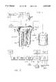
- FIG. 1is a front perspective view, partially in schematic form, illustrating a water purification system and related water quality monitor embodying the novel features of the invention
- FIG. 2is an enlarged fragmented vertical sectional view taken generally on the line 2--2 of FIG. 1;
- FIG. 3is an enlarged fragmented vertical sectional view corresponding generally with a portion of FIG. 2, and showing an inlet shut-off valve in a fully open position;
- FIG. 4is an enlarged fragmented vertical sectional view generally similarly to FIG. 3, and illustrating the inlet shut-off valve in a partially closed position;
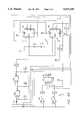
- FIG. 5is a circuit block diagram illustrating the water quality monitor for use in the purification system of FIGS. 1-4;
- FIG. 7is a fragmented sectional view, shown somewhat in schematic form, depicting an improved flow switch for use in the invention.
- FIG. 8is a portion of a circuit diagram reflecting one alternative preferred form of the invention, for implementation into the circuit diagram of FIG. 6.
- a water purification system referred to generally in FIG. 1 by the reference numeral 10includes a reverse osmosis unit 12 for producing relatively purified water from an ordinary tap water supply 14 or the like.
- the produced purified wateris collected within a suitable storage reservoir 16 and/or dispensed on demand, as by means of a faucet valve 18 or the like.
- a water quality monitor referred to generally by reference numeral 20is provided for testing the purity level of produced purified water, and for indicating the purity level as by illumination of appropriate indicator lights (not shown in FIG. 1).
- the water quality monitor 20is adapted to operate in response to normal cyclic operation of the reverse osmosis unit 12, to provide accurate and reliable test readings indicating system performance.
- the water purification system 10is designed particularly for use in residential and other domestic applications to provide a readily available supply of purified water.
- the purification system 10utilizes principles of reverse osmosis to convert the tap water inflow 14 into a pair of water outflows respectively comprising the relatively purified water having contaminants removed therefrom, and a waste or reject water supply having contaminants and/or impurities concentrated therein.
- the produced purified wateris normally coupled to the storage reservoir 16 for collection and storage, and also to the faucet valve 18 for dispensing on demand for drinking, cooking, etc.
- One or more parallel-connected dispense paths to a refrigerator ice maker (not shown) and the likemay also be provided.
- the reject water supplyoften referred to as brine is normally discharged to a suitable drain.
- FIGS. 1 and 2show the purification system 10 in a preferred configuration, in conformance with the water purification system disclosed in U.S. Pat. No. 5,045,197, which is incorporated by reference herein.
- the purification system 10comprises a unitized manifold 22 which supports three processor stages 24, 26, and 28 for converting the tap water inflow 14 into the separated purified and reject water supplies, as described above.
- the first stage 24comprises an initial filtration or prefilter stage for flow-through passage of the tap water inflow 14 through a prefilter cartridge 30 (FIG. 2) to remove particulate therefrom.
- the resultant prefiltered tap waterpasses to the second stage 26, which comprises the reverse osmosis unit 12 and includes a reverse osmosis semipermeable membrane 32 (FIG. 2).
- the membrane 32functions to separate the tap water inflow 14 into the purified and reject water supplies.
- the reject water supplyis connected through a suitable drain fitting 34 (FIG. 1) for passage to the drain, whereas the produced purified water is connected to the third or final stage 28 comprising a postfilter stage.
- the purified waterflows through a postfilter cartridge 36 and further through a tank fitting 38 for collection and storage within the reservoir 16, or through a dispense fitting 40 for delivery and dispensing via the faucet valve 18 or the like.
- An inlet shut-off valve 42is carried by the manifold 22 and responds to the level of produced purified water within the reservoir 16 to cycle the system between an "on" state and an "off” state. More particularly, as shown best in FIGS. 2-4, the inlet shut-off valve 42 comprises a valve member 44 of differential area mounted on a resilient diaphragm for opening and closing movement to respectively permit and prevent tap water inflow to the reverse osmosis unit 12. In the preferred form, a lower and relatively small area face of the valve member 44 is subjected to the pressure of the tap water supply by direct communication with a discharge port 46 associated with a downstream side of the prefilter stage 24.
- valve member 44An upper and comparatively larger surface area of the valve member 44 is exposed to the pressure of produced purified water within a pressure chamber 47 connected via a pressure port 48 to produced purified water discharged from the reverse osmosis unit 12. Accordingly, the pressure within the chamber 47 corresponds to the pressure of purified water within the reservoir 16.
- the valve member 44responds to the pressure differential applied thereto, for shutting off tap water inflow when the reservoir 16 reaches a substantially filled condition.
- the valve memberresponds to this same pressure differential to open and permit resumed tap water inflow when a sufficient quantity of the purified water is dispensed, as by opening the faucet valve 18, to reduce the pressure within the reservoir 16.
- a tapered poppet stem 45 shown in dotted lines in FIG. 3may be provided between the valve member 44 and the port 46 to enhance smooth transition movement of the valve member between the open and closed positions. This poppet stem 45 may be free floating, or attached to the valve member.
- the membrane 32 of the reverse osmosis unit 12is subjected to a substantial pressure differential enabling production of purified water.
- the produced purified wateris coupled for flow into the reservoir 16, wherein the reservoir commonly includes an internal resilient bladder 49 (FIG. 1) which subdivides the reservoir interior into a gas-filled pressure chamber and a water chamber for receiving and storing the purified water.
- the bladder 49deforms to reduce the volume of the pressure chamber and thereby result in a progressively increased pressure applied to the purified water.
- the pressure differential across the reverse osmosis unit 12gradually decreases.
- the operating efficiency of the reverse osmosis membrane 32is in part dependent upon the magnitude of the pressure differential applied thereto. This same pressure differential is applied as described above across the valve member 44.
- the shut-off valve 42is designed to close when this pressure differential across the membrane 32 reaches a predetermined but still substantial minimum level.
- the valve member 44 of the shut-off valve 42is designed with appropriate differential upper and lower surface areas to close when the pressure of the produced purified water reaches a predetermined threshold of about 40 psi. This closure operation is achieved by exposing the larger upper surface area of the valve member 44 to the pressure of produced purified water, in contrast with the proportionately smaller lower surface area of the valve member exposed through the port 46 to the tap water supply pressure.
- the shut-off valve 42is conveniently designed for snap-action movement to a substantially full-open position by providing an annular valve seat 54 engaged by the lower side of the valve member 44 in the closed position, wherein the valve seat 54 is surrounded by an annular gallery 56 coupled to a flow passage 58 leading to the reverse osmosis unit 12.
- shut-off valve constructionassures that a substantial quantity of the purified water will be dispensed from the full reservoir before the shut-off valve will open, thereby also assuring that the system will thereafter operate for a substantial period of time to produce purified water to re-fill the reservoir.
- the flow area of the port 46 in combination with the gallery 56provide dispensing of about one gallon from a full three gallon reservoir before the inlet shut off valve opens.
- the pressure differential across the valve member 44decreases at a slow rate since purified water production proceeds at a relatively slow flow rate.
- the pressure differential across the valve member 44approaches a condition causing the valve member 44 to displace slowly toward the closed position.
- this pressure differentialdecreases, and the valve member 44 moves slowly to the closed position, it is known that the operating efficiency of the reverse osmosis membrane 32 also decreases.
- the water quality monitor 20 of the present inventionresponds to the above-discussed cyclic operation of the purification system to take water quality test readings within a restricted portion of the system operation cycle when the reverse osmosis unit 12 is substantially at maximum operating efficiency. That is, the present invention recognizes that closure of the inlet shut-off valve 42 removes the pressure differential across the reverse osmosis membrane 32, such that some of the previously-removed contaminants and impurities can leach or migrate across the membrane to contaminate localized portions of the previously produced purified water within pure water flow paths of the system manifold 22.
- the improved water quality monitor of the present inventionthus does not take test readings within a period of time that the inlet shut-off valve is closed, or immediately after opening thereof, to avoid inadvertent and inaccurate reading of a localized pocket of poor quality water.
- the present inventiondoes not take a test reading during the period of time that the shut-off is near the closed condition, since the reduced pressure differential causes the reverse osmosis unit to function at less than maximum operating efficiency. Instead, all test readings are taken during system operation with a substantially optimum pressure differential across the reverse osmosis unit, referred to herein as mid-cycle.
- the test readingsare stored in memory for subsequent and periodic display, for example, each time the faucet valve 18 is opened to dispense water.
- a shuttle piston 62carries a magnet 64 in close association with a reed switch 66 mounted above the shut-off valve.
- a low force spring 68may be provided to ensure piloted back-and-forth movement of the shuttle piston 62 and magnet thereon with the diaphragm-mounted valve member 44.
- the reed switch 66is positioned to be closed each time the valve member 44 moves to the full open position.
- the magnet 64switches the reed switch 66 to an open state.
- This opening and closure movement of the reed switch 66is effective to operate the water quality monitor 20, as will be described in more detail.
- the reed switch 66is moved to the open state when the shut-off valve member 44 is about half-way toward the closed position, it will be understood that this may and will often occur at a point in time which is more than half-way between valve member opening and subsequent closure.
- FIG. 5is a schematic block diagram illustrating the structure and functional operation of the water quality monitor.
- the reset switch 60is connected to a convenient and appropriate power source, such as a 9-volt battery 70.
- a charging circuit 72is connected to the battery 70.
- the charging circuit 72functions to develop an appropriate electrical charge which is stored until the reed switch 66 opens.
- opening movement of the reed switch 66occurs in response to movement of the shut-off valve member 44 to a position reflective of a mid-cycle condition of the reverse osmosis unit 12, wherein the system is operating substantially at full pressure to produce purified water.
- the charging circuitdelivers a pulse to a monitor circuit 74 to couple an appropriate test pulse to a tap water electrode 76 and to a pure water electrode 78.
- These electrodesare conveniently mounted at appropriate positions along flow paths within the manifold 22, as shown in FIG. 2.
- the monitoring circuit 74functions to determine the comparative conductivities of the tap water inflow 14 and produced purified water, for purposes of monitoring the operating efficiency of the reverse osmosis unit 12.
- the test reading taken by the monitor circuit 74is delivered to a memory 80 for storage and subsequent display.
- the monitoring circuit 74may take any one of several forms known in the art, particularly such as those monitoring circuits described in U.S. Pat. Nos. 5,057,212 and 5,145,575, which are incorporated by reference herein.
- the test reading stored in memory 80is subsequently and periodically displayed by means of an appropriate signal such as indicator lights 82.
- the displayis triggered each time pure water is dispensed such as when the faucet valve 18 is opened, which correspondingly causes a flow switch 84 or the like to trigger the memory 80 for purposes of displaying the stored test reading via energization of the appropriate indicator light 82.
- a green indicator lightcan be illuminated when the conductivity test reading stored in memory indicates acceptable quality of the purified water.
- a yellow indicator lightcan be illuminated when the test reading indicates unacceptable water quality. When the water quality is unacceptable, proper system performance is typically restored by changing the reverse osmosis membrane 32.
- the water quality monitor 20is also designed, in preferred form, to operate the indicator lights 82 in a manner signalling other system conditions for which remedial action may be desirable or necessary.
- the bank of indicator lights 82is operated by a light driver circuit 86 adapted to receive auxiliary inputs reflective of important system conditions.
- one auxiliary inputis obtained from a pressure sensor or switch 88 which indicates the tap water pressure at the downstream side of the prefilter stage 24.
- the light driver circuit 86responds to operate the indicator lights 82 in a known manner, for example, by illuminating all of the lights simultaneously.
- the light driver circuit 86also receives an input from the battery 70. When the detected battery voltage falls below a threshold level, indicating that the battery 70 needs to be replaced, the driver circuit 86 responds to control the indicator lights in a manner reflecting low battery power, such as by preventing illumination of any light when a test reading should normally be displayed.
- Another input to the light driver circuit 86is obtained from a counter 90 which counts the number of times that the flow switch 84 is operated by opening the faucet valve 18, without closure of the inlet shut-off valve 12.
- a counter 90which counts the number of times that the flow switch 84 is operated by opening the faucet valve 18, without closure of the inlet shut-off valve 12.
- long-term operation of the purification system 10 without periodic closure of the shut-off valve 42normally indicates a mechanical failure of the shut-off valve 42.
- the counter 90thus signals the light driver circuit 86 when this condition occurs so that the indicator lights will be operated in a known manner, such as by illumination of a red indicator light.
- the light driver circuitmay include a timer 91 to control the duration of time that the indicator lights 82 are energized.
- the timer 91may be set to conveniently extinguish an energized indicator light after a few seconds of illumination, such that the desired indication is provided without excess power drain on the battery 70.
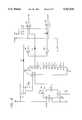
- FIGS. 6A-6Dshow the water quality monitor 20 in a preferred circuit implementation in accordance with the functional operating features described above. It will be understood by persons skilled in the art, however, that these functional features can be carried out in a variety of different circuit arrangements.
- closure of the reed switch 66connects the monitor circuit to the battery 70 to charge a capacitor C5 to a voltage level corresponding with battery voltage.
- the circuitis designed to charge the capacitor C5 over a time period sufficiently long so that mechanical rebound or bounce of the shut-off valve does not impact operation of the charging circuit 72.
- the charge stored by the capacitor C5is discharged through a NAND gate U5C and a resistor R2, causing the output of the NAND gate U5C to be delivered as a pulse to the set pin of a flip-flop U4A.
- the set pulsefunctions to set the flip-flop U4A so that the "Q" output is high and the "not Q” output is low.
- the "not Q” low outputbiases a transistor Q3 to an "on” state, resulting in connection of the battery 70 to the input of a voltage regulator U6.
- This voltage regulator U6regulates the voltage applied to the circuit components to a constant level of about 5-volts.
- the high output at the "Q" terminal of the flip-flop U4Aturns a diode D3 to an “off” state, and thereby allows a clock U5B, U5A to switch to an "on” state.
- a counter U2is also reset by the same "Q" high output of the flip-flop U4A.
- the monitor circuit 74 that generates the test pulse for taking conductivity readingsis comprised of flip-flops U3A, U3B, and the clock U5B, U5A.
- the "Q" output of flip-flop U3Ais connected to the tap water electrode 76, and the "Q" output of flip-flop U3B is connected to the pure water electrode 78.
- An output capacitor C8 of the voltage regulator U6charges, when the reed switch 66 is opened, in a short period of time, about 6 milliseconds before reaching the regulated voltage output.
- the flip-flops U3A, U3B that generate the test pulse applied to the electrodesare held in a reset condition for approximately 10 milliseconds, comprising the time for a capacitor C1 to charge to a voltage level insufficient to reset the flip-flops U3A, U3B.
- This short time delayalso allows the clock U5B, U5A to turn on and stabilize.
- the flip-flops U3A, U3Bbecome active.
- the first clock cyclecauses the "Q" output of the flip-flop U3A to go high while the "Q" output of the flip-flop U3B remains low, thereby making the pure water electrode 78 negative with respect to the tap water electrode 76.
- the second clock cyclecauses the "Q" output of the flip-flop U3B to go high, such that the potential between the “Q” outputs of the two flip-flops U3A, U3B is zero.
- the third clock cyclecauses the "Q" output of the flip-flop U3A to go low, thus making the pure water electrode 78 positive with respect to the negative tap water electrode 76.
- the fourth clock cyclecauses the "Q" output of the flip-flop U3B to go low, making the potential between the electrodes 76, 78 zero.
- the negative pulse through the electrodes 76, 78 on the first clock cycleis ignored with respect to taking a conductivity reading.
- the pulse applied to the electrode 78is positive, that pulse is also applied to a voltage divider circuit defined by resistors R4, R5 and an adjustable potentiometer TR1.
- the potentiometer TR1is set to apply a proportional or comparative voltage to the negative terminal of a comparator U1B, the positive terminal of which is connected to a common electrode 92.
- the comparison voltage representing the proportionate conductivity readings of the pure and tap water suppliesexceed a reference point selected by adjustment of the potentiometer TR1, the output of the comparator will go high and indicate that pure water production is of unacceptable quality.
- the comparison voltage applied to the comparator U1Bis less than the reference, the output of the comparator U1B is low and indicates that the condition of produced purified water is acceptable.
- the test reading on the output side of comparator U1Bis connected to the data input of a flip-flop U4B for the duration of the positive test pulse.
- the "Q" output of the flip-flop U3Bswitches to the low state, causing a transistor Q2 to turn “off", which in turn produces a positive clock edge pulse to be delivered to flip-flops U4A, U4B.
- the datais stored by the flip-flop U4B. Specifically, if the signal to the data input pin of the flip-flop U4B is low, indicating acceptable water quality, the state of the flip-flop U4B remains unchanged. However, if the data signal is high, indicating unacceptable water quality, the clock pulse changes the state of the flip-flop U4B so that its output "Q" is high and the output "not Q" is low.
- the clock pulse referenced aboveis also supplied to the data input line of the flip-flop U4A.
- the clock pulsecauses the "Q" output of the flip-flop U4A to go low and the “not Q” output to go high, thereby removing the bias from the transistor Q3 in order to switch that transistor Q3 to an “off” state.
- the transistor Q3turns “off”
- the voltage regulator U6is disconnected from the battery 70 and the monitoring circuit is now in an "off” state.
- the flow switch 84connects the circuit to the battery 70, causing a capacitor C2 to charge. Instantaneously this applies battery voltage to the input of NAND gate U5D. While this voltage exceeds the threshold voltage of NAND gate U5D, the output of the NAND gate U5D goes low and biases the transistor Q3 to an "on" state. Accordingly, once again, the battery 70 is connected by the transistor Q3 to the voltage regulator U6, thereby turning on the voltage regulator and other circuit components.
- a pair of voltage dividers including resistors R8, R23 and R9, R28are connected to an amplifier U1D for biasing the display circuitry and also to provide an indication of a low battery voltage condition.
- the output of the amplifier U1Dwill be low to activate another voltage divider R10, R24.
- This voltage dividerhas a junction between R10 and R24 connected to comparators U1A and U1C, to create a reference voltage for the display circuitry.
- the other terminals of these two comparatorsare connected respectively to the "Q" and “not Q" outputs of the flip-flop U4B within which the test reading data has been stored, as previously described.
- the "Q" output of the flip-flop U4Bis low and the “not Q” output of the flip-flop U4B is high.
- the yellow indicator lightis disabled and the green indicator light is enabled to indicate visually the previously stored test reading, namely, that system operational performance is within acceptable limits.
- the green indicator lightis disabled and the yellow indicator light is enabled, to indicate unacceptable system performance.
- the pressure switchconnects the circuit common (ground) to the plus terminal of the comparators U1A and U1C, causing both comparators to have a low output and thereby enabling both of the yellow and green indicator lights when the faucet valve is open. When both lights are illuminated, the display thus indicates that the prefilter cartridge 30 should be replaced.
- the counter 90is provided as part of the circuitry to count the number of times that the flow switch 84 is closed upon opening of the faucet valve 18, without return movement of the reed switch 66 to a full open position at the conclusion of an off cycle.
- the NAND gate U5Dproduces a low output.
- a capacitor C6discharges through a resistor R19, such that a clock input of the counter 90 (U2) increments one count.
- the counter 90increments each time the faucet valve is opened, but resets to zero when the reed switch 66 opens upon resumption of tap water flow following a system off cycle.
- a red indicator lightis enabled to provide a visual indication that a system failure has occurred.
- this failureis attributable to a mechanical failure of the inlet shut-off valve, with the total accumulated in the counter 90 representing the time that the shut-off valve has remained open, without cycling to the closed position.
- the counteressentially acts as a timer to mark opening movement of the shut-off valve, and then clocks the time that the shut-off valve remains open, thereby to provide the appropriate signal if the shut-off valve does not cycle to the closed position in a reasonable period of time.
- alternative time methods and devicesmay be used to provide this system function.
- a battery switch 73(FIG. 6A) is conveniently provided for initial system installation, to set the monitor circuit 74 in a condition to indicate acceptable water quality, pending actual conductivity readings at mid-cycle conditions.
- the battery switch 73is normally closed, and connects power to the reset pin 10 of the flip-flop U4B via a resistor R30 and a capacitor C9 (FIG. 6C). After a short charge time for capacitor C9, the voltage applied to pin 10 is low, whereby the monitor circuit 74 will energize the green indicator light when the flow switch 84 is closed.
- the circuitrycan be set to indicate acceptable water quality by opening and closing the battery switch 73, thus permitting verification that the green indicator light is operational. Of course, during subsequent normal cyclic system operation, the indicator light will be energized according to actual conductivity test readings.
- FIG. 7shows one preferred form for the flow switch 84, installed along a dispense flow path leading from the dispense fitting 40 (FIGS. 1 and 2) to the faucet 18.
- the flow switch 84includes a spring-loaded poppet 102 which moves to an open position relative to a flow port 104, when the faucet 18 or other dispense device is opened to initiate a dispense water flow.
- the degree of movement or displacement of the poppet 102is a direct function of the volumetric flow rate through the dispense flow path.
- the poppet 102is slidably carried on a guide stem 106 having a reed switch 108 or the like fitted into a rear side counterbore 110 of the poppet.
- a magnet 112 carried by the poppetis displaced over the reed switch 108 sufficiently to close the reed switch and supply power from the battery source to a flow volume monitor 114.
- the thus-energized monitor 114then receives signals from a poppet position detector 116, such as a Hall effect transducer capable of tracking the poppet by monitoring the position of the magnet 112. Alternate poppet position sensors such as optical sensors may be used.
- the position sensor 116signals the flow volume monitor 114 regarding poppet position when open so that a running accumulation of actual water volume dispensed can be derived.
- the flow volume monitor 114can be appropriately coupled to the light driver circuit 86 as viewed in FIG. 7 to energize the indicator lights in a manner indicating that a predetermined volume of pure water has been dispensed. When this occurs, it may be necessary or desirable to replace the filter cartridge 36 of the postfilter stage 28.
- FIG. 8shows an alternative preferred form of the monitor circuit, particularly with respect to a modification adapted for implementation into the circuit diagram shown in FIGS. 6A-6D.
- the modified portion of the monitor circuit shown in FIG. 8includes a labelling scheme which is consistent with FIGS. 6A-6D, with circuit connections broken off and inclusive of identification of the component or components in FIGS. 6A-6D to be connected thereto.
- FIG. 8discloses circuit means for requiring a selected successive number of unacceptable water quality test readings before the yellow indicator light is actually illuminated. That is, as will be described, the circuit of FIG. 8 will cause the green indicator light to be energized despite the actual test reading stored in memory indicative of unacceptable water quality, unless and until three consecutive test readings indicate unacceptable water quality. With this variation, there is little or no chance that three consecutive false "unacceptable" readings will occur, for whatever reason, such that the yellow light will not be energized unless the reverse osmosis unit is consistently producing water of unacceptable quality.
- the flip-flop U4Bis coupled to the comparators U1A and U1B through a counter U7 and inverters U8E and U8F.
- the "Q" output of U4Bis unconnected, whereas the “not Q” output is connected to the reset input of the counter U7.
- the counter U7remains in a reset condition and the green indicator light is enabled via the comparator U1C for energization when the faucet valve is opened, in the same manner as previously described.
- the output Q2 of the counter U7is connected via the diode D1 to the inverting input of the comparator U1A, thus inhibiting or disabling the yellow indicator light.
- This output Q2is also connected to the inputs of the inverters U8E and U8F, with the output of the latter inverter U8F being connected via the diode D2 to the inverting input of the comparator U1C, such that the green indicator light is enabled.
- the flip-flop U4BWhen the flip-flop U4B receives a test reading indicative of unacceptable water quality, the "not Q" output switches to a low state to remove the reset from the counter U7.
- the clock input of U7is connected through a time delay circuit R31, C10 to the clock input of the flip-flop U4B.
- the reset condition for the counter U7is removed.
- the next consecutive test reading indicative of unacceptable water qualitycauses the output Q1 of the counter U7 to go high, and the third consecutive test reading of unacceptable water quality yields a high output on the counter output Q2 connected to the comparators U1A and U1C as previously described.
- the high output on Q2functions through the inverter U8F and comparator U1C to disable the green indicator light, while turning “off” the diode D1 to enable the yellow indicator light via the comparator U1A.
- the output of the inverter U8Einhibits the counter U7 from accepting any more counts prior to reset, whereby the yellow light will be enabled unless and until counter reset occurs. Such reset does occur whenever a subsequent test reading reflective of acceptable water quality yields a high "not Q" output from the flip-flop U4B.
- the counter U7is reset in this manner, the green indicator light will be enabled until three successive "unacceptable” water quality readings occur.
- the number of "unacceptable" readings in succession needed to enable the yellow indicator lightmay be varied by appropriate connection of the outputs Q1-Q12 of the counter U7.
- the inventionthus provides an improved water monitoring circuit and system wherein all conductivity test readings are taken during a period of time when the reverse osmosis unit 12 is operating substantially at maximum performance level.
- test readingsare not taken during periods of operation at a performance level less than optimum, such as immediately after tap water flow is resumed to the system following an off cycle, or immediately prior to closure of an inlet shut-off valve at the on set of an off cycle.
- the conductivity test reading sare taken substantially during a mid-cycle operating condition.
- the readingis stored and subsequently displayed, in the preferred form, each time a faucet valve is opened to dispense water. A selected number of "unacceptable" water quality readings may be required in succession before an indication of unacceptable water quality is provided.
- the monitor 20can be operated by various trigger signals to take a test reading at a mid -cycle condition of the reverse osmosis unit 12, such as by operating the charging circuit 72 in response to water level detectors within the reservoir.
- alternate meanscan be provided for displaying the test reading held in memory, such as clock means for displaying the stored test reading at regularly timed intervals.
Landscapes
- Engineering & Computer Science (AREA)
- Chemical & Material Sciences (AREA)
- Water Supply & Treatment (AREA)
- Nanotechnology (AREA)
- Chemical Kinetics & Catalysis (AREA)
- Physics & Mathematics (AREA)
- General Physics & Mathematics (AREA)
- Automation & Control Theory (AREA)
- Separation Using Semi-Permeable Membranes (AREA)
- Water Treatment By Sorption (AREA)
Abstract
Description
Claims (6)
Priority Applications (1)
| Application Number | Priority Date | Filing Date | Title |
|---|---|---|---|
| US08/309,426US5527450A (en) | 1994-03-14 | 1994-09-20 | Water conductivity monitor for a water purification system |
Applications Claiming Priority (2)
| Application Number | Priority Date | Filing Date | Title |
|---|---|---|---|
| US08/212,362US5580444A (en) | 1994-03-14 | 1994-03-14 | Water quality monitor for a water purification system |
| US08/309,426US5527450A (en) | 1994-03-14 | 1994-09-20 | Water conductivity monitor for a water purification system |
Related Parent Applications (1)
| Application Number | Title | Priority Date | Filing Date |
|---|---|---|---|
| US08/212,362Continuation-In-PartUS5580444A (en) | 1994-03-14 | 1994-03-14 | Water quality monitor for a water purification system |
Publications (1)
| Publication Number | Publication Date |
|---|---|
| US5527450Atrue US5527450A (en) | 1996-06-18 |
Family
ID=22790687
Family Applications (2)
| Application Number | Title | Priority Date | Filing Date |
|---|---|---|---|
| US08/212,362Expired - Fee RelatedUS5580444A (en) | 1994-03-14 | 1994-03-14 | Water quality monitor for a water purification system |
| US08/309,426Expired - Fee RelatedUS5527450A (en) | 1994-03-14 | 1994-09-20 | Water conductivity monitor for a water purification system |
Family Applications Before (1)
| Application Number | Title | Priority Date | Filing Date |
|---|---|---|---|
| US08/212,362Expired - Fee RelatedUS5580444A (en) | 1994-03-14 | 1994-03-14 | Water quality monitor for a water purification system |
Country Status (7)
| Country | Link |
|---|---|
| US (2) | US5580444A (en) |
| EP (1) | EP0672448B1 (en) |
| JP (1) | JP3590664B2 (en) |
| CA (1) | CA2143516C (en) |
| DE (1) | DE69502755T2 (en) |
| ES (1) | ES2119245T3 (en) |
| IL (1) | IL112792A (en) |
Cited By (32)
| Publication number | Priority date | Publication date | Assignee | Title |
|---|---|---|---|---|
| US5888381A (en)* | 1997-05-16 | 1999-03-30 | United States Filter Corporation | Water filter with pressure actuated flow monitor |
| US6003318A (en)* | 1998-04-28 | 1999-12-21 | Oasis Corporation | Thermoelectric water cooler |
| WO2002036233A3 (en)* | 2000-11-03 | 2003-03-13 | Amcol International Corp | Removing oil from water, monitoring of adsorbent saturation |
| US20040251192A1 (en)* | 2003-05-02 | 2004-12-16 | Karl Fritze | Crossflow filtration system with quick dry change elements |
| US20050173319A1 (en)* | 2003-05-02 | 2005-08-11 | Karl Fritze | Crossflow filtration system with quick dry change elements |
| US20060011526A1 (en)* | 2004-07-15 | 2006-01-19 | Baarman David W | Remotely controllable outlet for water treatment system |
| US20060144765A1 (en)* | 2004-12-30 | 2006-07-06 | Timothy Skwiot | Conductivity measurement and monitoring system for a fluid treatment system |
| US20060272997A1 (en)* | 2005-06-06 | 2006-12-07 | Hsin-Fa Liu | Reverse osmosis filtering assembly |
| US20070045165A1 (en)* | 2005-08-26 | 2007-03-01 | Next-Ro, Inc. | Reverse osmosis filtration systems |
| US20070045327A1 (en)* | 2005-08-26 | 2007-03-01 | Next-Ro, Inc. | Reverse osmosis filtration system storage tanks |
| US7775374B1 (en) | 2007-11-15 | 2010-08-17 | Barker Jack E | Self powered water purification system |
| EP1830180A3 (en)* | 2006-03-01 | 2010-08-25 | Whirlpool Corporation | Water conductivity monitoring circuit for use with a steam generator |
| US20120138523A1 (en)* | 2008-10-10 | 2012-06-07 | Matula Paul A | Multi-flow filtration system |
| US8409386B1 (en) | 2010-02-22 | 2013-04-02 | Next-Ro, Inc. | Storage tank assemblies and methods for water on water reverse osmosis systems |
| US8671985B2 (en) | 2011-10-27 | 2014-03-18 | Pentair Residential Filtration, Llc | Control valve assembly |
| US8961770B2 (en) | 2011-10-27 | 2015-02-24 | Pentair Residential Filtration, Llc | Controller and method of operation of a capacitive deionization system |
| US9010361B2 (en) | 2011-10-27 | 2015-04-21 | Pentair Residential Filtration, Llc | Control valve assembly |
| CN106092466A (en)* | 2016-08-20 | 2016-11-09 | 安徽省泽业环保科技有限公司 | Water purifier is performance test bed |
| US9637397B2 (en) | 2011-10-27 | 2017-05-02 | Pentair Residential Filtration, Llc | Ion removal using a capacitive deionization system |
| US9695070B2 (en) | 2011-10-27 | 2017-07-04 | Pentair Residential Filtration, Llc | Regeneration of a capacitive deionization system |
| US9731984B2 (en) | 2010-02-19 | 2017-08-15 | Topper Manufacturing Corporation | Reverse osmosis systems with built in pressure regulation |
| US10123556B2 (en) | 2005-05-06 | 2018-11-13 | Whirlpool Corporation | Method for cooking food using steam |
| CN110208330A (en)* | 2019-06-28 | 2019-09-06 | 江苏核电有限公司 | A kind of device and measurement method of continuous measurement water tank deionized water conductivity variations |
| US10844533B2 (en) | 2007-05-07 | 2020-11-24 | Whirlpool Corporation | Method for controlling a household washing machine |
| US11052333B2 (en)* | 2018-06-27 | 2021-07-06 | Kx Technologies Llc | Filter interconnect using a correlated magnet torque design |
| US11326379B2 (en) | 2019-08-28 | 2022-05-10 | Kx Technologies Llc | Filter interconnects utilizing magnetic shear force generated by coded polymagnets |
| US11346830B2 (en) | 2020-07-20 | 2022-05-31 | International Business Machines Corporation | Predictive water condition monitoring |
| US20230166203A1 (en)* | 2020-04-28 | 2023-06-01 | Amogreentech Co., Ltd. | Filter module for gravity-type water-purifying device and comprising the same |
| US11712645B2 (en) | 2019-05-17 | 2023-08-01 | Kx Technologies Llc | Filter interconnect utilizing correlated magnetic actuation for downstream system function |
| US11779865B2 (en) | 2020-04-21 | 2023-10-10 | Kx Technologies Llc | Gravity-fed filter interconnect utilizing coded polymagnets |
| US11931679B2 (en) | 2019-05-17 | 2024-03-19 | Kx Technologies Llc | Filter interconnect utilizing a magnetic repulsion force |
| US11944924B2 (en) | 2020-04-27 | 2024-04-02 | Kx Technologies Llc | Filter interconnect using a magnetic shear force |
Families Citing this family (60)
| Publication number | Priority date | Publication date | Assignee | Title |
|---|---|---|---|---|
| JP3035379U (en)* | 1996-05-09 | 1997-03-18 | 二夫 高嶋 | Reverse osmosis water purifier with automatic valve for water supply and drainage system |
| US6258278B1 (en) | 1997-03-03 | 2001-07-10 | Zenon Environmental, Inc. | High purity water production |
| US6267891B1 (en) | 1997-03-03 | 2001-07-31 | Zenon Environmental Inc. | High purity water production using ion exchange |
| US6379560B1 (en)* | 2000-03-08 | 2002-04-30 | Barnstead/Thermodyne Corporation | Water purifying apparatus and method for purifying water |
| US6472624B1 (en) | 2000-09-26 | 2002-10-29 | Gp Companies, Inc. | In-line flow switch |
| US20050279696A1 (en) | 2001-08-23 | 2005-12-22 | Bahm Jeannine R | Water filter materials and water filters containing a mixture of microporous and mesoporous carbon particles |
| US7614507B2 (en) | 2001-08-23 | 2009-11-10 | Pur Water Purification Products Inc. | Water filter materials, water filters and kits containing particles coated with cationic polymer and processes for using the same |
| US7614508B2 (en) | 2001-08-23 | 2009-11-10 | Pur Water Purification Products Inc. | Water filter materials, water filters and kits containing silver coated particles and processes for using the same |
| US7615152B2 (en) | 2001-08-23 | 2009-11-10 | Pur Water Purification Products, Inc. | Water filter device |
| KR100777951B1 (en) | 2001-08-23 | 2007-11-28 | 더 프록터 앤드 갬블 캄파니 | Water filter material, corresponding water filter and method of use thereof |
| EP1539334A4 (en) | 2002-08-12 | 2005-11-16 | Ge Osmonics Inc | Residential reverse osmosis system |
| US7017611B2 (en)* | 2003-02-04 | 2006-03-28 | Watts Regulator C. | One-piece manifold for a reverse osmosis system |
| WO2004069368A2 (en)* | 2003-02-04 | 2004-08-19 | Watts Regulator Co. | One-piece manifold for a reverse osmosis system |
| USD501912S1 (en) | 2003-08-19 | 2005-02-15 | Procter & Gamble | Water filter device |
| JP4543657B2 (en)* | 2003-10-31 | 2010-09-15 | ソニー株式会社 | Information processing apparatus and method, and program |
| WO2005046830A2 (en)* | 2003-11-12 | 2005-05-26 | Watts Regulator Co. | Zero waste reverse osmosis water filtering |
| US20060151393A1 (en)* | 2005-01-07 | 2006-07-13 | Badger Timothy J | Water purification and disenfection device and method |
| US7465399B1 (en)* | 2005-02-28 | 2008-12-16 | Hoeptner Iii Herbert W | Filtered and unfiltered water ducting in sink fitting |
| JP4774823B2 (en)* | 2005-06-16 | 2011-09-14 | ソニー株式会社 | Wireless communication system, wireless communication setting method, wireless communication apparatus, wireless communication setting program, and wireless communication setting program storage medium |
| US7743788B2 (en)* | 2005-06-17 | 2010-06-29 | Watts Regulator Co. | Faucet assembly with water quality indicator |
| US7912017B2 (en)* | 2005-06-29 | 2011-03-22 | Sony Corporation | Wireless connection system and wireless connection method |
| TWM290513U (en)* | 2005-08-23 | 2006-05-11 | Shr-Ping Li | Detachable structure of water preservation tank of osmosis filtering water purification device |
| DE102006015673A1 (en)* | 2006-04-04 | 2007-10-11 | Wapura Trinkwasserreinigungs Gmbh | Small volume reverse osmosis plant with concentrate management |
| US7505857B2 (en)* | 2006-08-22 | 2009-03-17 | H2Observe, Llc | Water quality monitoring device and method |
| US20090123340A1 (en)* | 2007-05-04 | 2009-05-14 | H2Observe, Llc | Water quality monitoring device and method |
| JP4277052B1 (en)* | 2008-03-27 | 2009-06-10 | 株式会社日立製作所 | Operation control method of membrane filtration device |
| FR2932893B1 (en)* | 2008-06-23 | 2010-12-10 | Millipore Corp | METHOD AND DEVICE FOR MEASURING THE CONDUCTIVITY OF A PURE OR ULTRAPUR LIQUID. |
| JP5135385B2 (en)* | 2010-06-11 | 2013-02-06 | パナソニック株式会社 | Electrolyzed water generator |
| US20120174655A1 (en)* | 2011-01-12 | 2012-07-12 | Eberhard Essich | Contaminated water detecting and monitoring and warning device and system and method using single sensors in tandem or cascade |
| US8935938B2 (en)* | 2011-05-25 | 2015-01-20 | General Electric Company | Water filter with monitoring device and refrigeration appliance including same |
| US9995486B2 (en) | 2011-12-15 | 2018-06-12 | Honeywell International Inc. | Gas valve with high/low gas pressure detection |
| US8947242B2 (en) | 2011-12-15 | 2015-02-03 | Honeywell International Inc. | Gas valve with valve leakage test |
| US8839815B2 (en) | 2011-12-15 | 2014-09-23 | Honeywell International Inc. | Gas valve with electronic cycle counter |
| US9557059B2 (en) | 2011-12-15 | 2017-01-31 | Honeywell International Inc | Gas valve with communication link |
| US9851103B2 (en) | 2011-12-15 | 2017-12-26 | Honeywell International Inc. | Gas valve with overpressure diagnostics |
| US9846440B2 (en) | 2011-12-15 | 2017-12-19 | Honeywell International Inc. | Valve controller configured to estimate fuel comsumption |
| US8905063B2 (en) | 2011-12-15 | 2014-12-09 | Honeywell International Inc. | Gas valve with fuel rate monitor |
| US8899264B2 (en) | 2011-12-15 | 2014-12-02 | Honeywell International Inc. | Gas valve with electronic proof of closure system |
| US9835265B2 (en) | 2011-12-15 | 2017-12-05 | Honeywell International Inc. | Valve with actuator diagnostics |
| US9074770B2 (en) | 2011-12-15 | 2015-07-07 | Honeywell International Inc. | Gas valve with electronic valve proving system |
| KR20130086496A (en)* | 2012-01-25 | 2013-08-02 | 한국전자통신연구원 | Apparatus and method for controlling fault of water quality sensor using sensor data |
| US10422531B2 (en) | 2012-09-15 | 2019-09-24 | Honeywell International Inc. | System and approach for controlling a combustion chamber |
| US9234661B2 (en) | 2012-09-15 | 2016-01-12 | Honeywell International Inc. | Burner control system |
| EP2868970B1 (en) | 2013-10-29 | 2020-04-22 | Honeywell Technologies Sarl | Regulating device |
| US10024439B2 (en) | 2013-12-16 | 2018-07-17 | Honeywell International Inc. | Valve over-travel mechanism |
| WO2015168596A1 (en) | 2014-05-01 | 2015-11-05 | Elkay Manufacturing Company | System and method for dispensing consumable liquids |
| US9841122B2 (en) | 2014-09-09 | 2017-12-12 | Honeywell International Inc. | Gas valve with electronic valve proving system |
| US9645584B2 (en) | 2014-09-17 | 2017-05-09 | Honeywell International Inc. | Gas valve with electronic health monitoring |
| CN104613231B (en)* | 2015-03-06 | 2017-03-01 | 成都懒宝网络科技有限公司 | A kind of intelligent tap that can detect water quality water purification |
| US10503181B2 (en) | 2016-01-13 | 2019-12-10 | Honeywell International Inc. | Pressure regulator |
| US10564062B2 (en) | 2016-10-19 | 2020-02-18 | Honeywell International Inc. | Human-machine interface for gas valve |
| US10780377B2 (en) | 2016-11-30 | 2020-09-22 | Watts Regulator Co. | Sanitizing filter system and method for a residential water filtering system |
| AT520515B1 (en)* | 2017-09-25 | 2022-03-15 | Scan Messtechnik Gmbh | Device for detecting the quality of a liquid in a supply pipe |
| CN107917933A (en)* | 2017-12-22 | 2018-04-17 | 深圳目科技有限公司 | A kind of total dissolved solid matter monitoring device |
| US11073281B2 (en) | 2017-12-29 | 2021-07-27 | Honeywell International Inc. | Closed-loop programming and control of a combustion appliance |
| US10836580B2 (en) | 2018-04-06 | 2020-11-17 | Intelligrated Headquarters, Llc | Conveyor cartridge with braking mechanism |
| US10239696B1 (en) | 2018-04-06 | 2019-03-26 | Intelligrated Headquarters, Llc | Conveyor cartridge |
| US10697815B2 (en) | 2018-06-09 | 2020-06-30 | Honeywell International Inc. | System and methods for mitigating condensation in a sensor module |
| US11162933B2 (en)* | 2019-09-11 | 2021-11-02 | Haier Us Appliance Solutions, Inc. | System and method for detecting heavy metals in a fluid |
| IT202100010016A1 (en)* | 2021-04-20 | 2022-10-20 | Inthebubble S R L | DETECTION SYSTEM FOR THE QUANTITATIVE ASSESSMENT OF THE BACTERIAL CHARGE IN WATER |
Citations (18)
| Publication number | Priority date | Publication date | Assignee | Title |
|---|---|---|---|---|
| US3838774A (en)* | 1973-01-02 | 1974-10-01 | N Ball | Apparatus for monitoring water purification system |
| US3990066A (en)* | 1974-10-25 | 1976-11-02 | Malmgren Arthur L | Water quality monitor |
| US4383221A (en)* | 1980-10-21 | 1983-05-10 | Millipore Corporation | Water resistivity sensor |
| US4623451A (en)* | 1985-02-19 | 1986-11-18 | Oliver Bruce J | Third faucet system with above sink purity indicator |
| US4708791A (en)* | 1986-12-04 | 1987-11-24 | Pjd Associates Inc. | Water quality monitor |
| US4762611A (en)* | 1987-09-16 | 1988-08-09 | Myron L Company, Inc. | Water quality indication system |
| US4806912A (en)* | 1987-06-19 | 1989-02-21 | Clack Robert A | Monitoring system for a liquid purification system |
| JPH01111485A (en)* | 1987-10-23 | 1989-04-28 | Toshiba Heating Appliances Co | Preparation device for potable water |
| US4849098A (en)* | 1988-04-07 | 1989-07-18 | Anthony Wilcock | Continuous water quality monitor |
| US4851818A (en)* | 1988-04-01 | 1989-07-25 | Eastman Kodak Company | Electronic controller for a water purifying unit |
| US4937557A (en)* | 1990-01-02 | 1990-06-26 | Aqua-Tronics, Inc. | Monitoring and indicating circuit for reverse osmosis filter |
| US4969363A (en)* | 1988-03-29 | 1990-11-13 | Aichi Tokei Denki Co., Ltd. | Electromagnetic flowmeter capable of simultaneous measurement of flow rate and conductivity of fluid |
| US5045197A (en)* | 1990-08-03 | 1991-09-03 | Burrows Bruce D | Reverse osmosis purification system with unitary header manifold |
| US5057212A (en)* | 1990-03-09 | 1991-10-15 | Burrows Bruce D | Water conductivity monitor and circuit with extended operating life |
| US5087883A (en)* | 1990-09-10 | 1992-02-11 | Mr. Coffee, Inc. | Differential conductivity meter for fluids and products containing such meters |
| US5096574A (en)* | 1990-01-16 | 1992-03-17 | Teledyne Industries, Inc. | Reverse osmosis system |
| US5145575A (en)* | 1990-03-09 | 1992-09-08 | Burrows Bruce D | Water quality monitor for a water purification system |
| US5435909A (en)* | 1994-03-14 | 1995-07-25 | Hydrotechnology, Inc. A California Corp. | Water quality monitor for a water purification system |
Family Cites Families (2)
| Publication number | Priority date | Publication date | Assignee | Title |
|---|---|---|---|---|
| US4784763A (en)* | 1987-07-13 | 1988-11-15 | Labconco Corporation | Water purification machine |
| US5441070A (en)* | 1993-11-10 | 1995-08-15 | Thompson; Gary E. | Fluid management system |
- 1994
- 1994-03-14USUS08/212,362patent/US5580444A/ennot_activeExpired - Fee Related
- 1994-09-20USUS08/309,426patent/US5527450A/ennot_activeExpired - Fee Related
- 1995
- 1995-02-26ILIL112792Apatent/IL112792A/ennot_activeIP Right Cessation
- 1995-02-27CACA002143516Apatent/CA2143516C/ennot_activeExpired - Lifetime
- 1995-03-07EPEP95103242Apatent/EP0672448B1/ennot_activeExpired - Lifetime
- 1995-03-07DEDE69502755Tpatent/DE69502755T2/ennot_activeExpired - Fee Related
- 1995-03-07ESES95103242Tpatent/ES2119245T3/ennot_activeExpired - Lifetime
- 1995-03-13JPJP05292095Apatent/JP3590664B2/ennot_activeExpired - Fee Related
Patent Citations (18)
| Publication number | Priority date | Publication date | Assignee | Title |
|---|---|---|---|---|
| US3838774A (en)* | 1973-01-02 | 1974-10-01 | N Ball | Apparatus for monitoring water purification system |
| US3990066A (en)* | 1974-10-25 | 1976-11-02 | Malmgren Arthur L | Water quality monitor |
| US4383221A (en)* | 1980-10-21 | 1983-05-10 | Millipore Corporation | Water resistivity sensor |
| US4623451A (en)* | 1985-02-19 | 1986-11-18 | Oliver Bruce J | Third faucet system with above sink purity indicator |
| US4708791A (en)* | 1986-12-04 | 1987-11-24 | Pjd Associates Inc. | Water quality monitor |
| US4806912A (en)* | 1987-06-19 | 1989-02-21 | Clack Robert A | Monitoring system for a liquid purification system |
| US4762611A (en)* | 1987-09-16 | 1988-08-09 | Myron L Company, Inc. | Water quality indication system |
| JPH01111485A (en)* | 1987-10-23 | 1989-04-28 | Toshiba Heating Appliances Co | Preparation device for potable water |
| US4969363A (en)* | 1988-03-29 | 1990-11-13 | Aichi Tokei Denki Co., Ltd. | Electromagnetic flowmeter capable of simultaneous measurement of flow rate and conductivity of fluid |
| US4851818A (en)* | 1988-04-01 | 1989-07-25 | Eastman Kodak Company | Electronic controller for a water purifying unit |
| US4849098A (en)* | 1988-04-07 | 1989-07-18 | Anthony Wilcock | Continuous water quality monitor |
| US4937557A (en)* | 1990-01-02 | 1990-06-26 | Aqua-Tronics, Inc. | Monitoring and indicating circuit for reverse osmosis filter |
| US5096574A (en)* | 1990-01-16 | 1992-03-17 | Teledyne Industries, Inc. | Reverse osmosis system |
| US5057212A (en)* | 1990-03-09 | 1991-10-15 | Burrows Bruce D | Water conductivity monitor and circuit with extended operating life |
| US5145575A (en)* | 1990-03-09 | 1992-09-08 | Burrows Bruce D | Water quality monitor for a water purification system |
| US5045197A (en)* | 1990-08-03 | 1991-09-03 | Burrows Bruce D | Reverse osmosis purification system with unitary header manifold |
| US5087883A (en)* | 1990-09-10 | 1992-02-11 | Mr. Coffee, Inc. | Differential conductivity meter for fluids and products containing such meters |
| US5435909A (en)* | 1994-03-14 | 1995-07-25 | Hydrotechnology, Inc. A California Corp. | Water quality monitor for a water purification system |
Cited By (53)
| Publication number | Priority date | Publication date | Assignee | Title |
|---|---|---|---|---|
| US5888381A (en)* | 1997-05-16 | 1999-03-30 | United States Filter Corporation | Water filter with pressure actuated flow monitor |
| US6003318A (en)* | 1998-04-28 | 1999-12-21 | Oasis Corporation | Thermoelectric water cooler |
| WO2002036233A3 (en)* | 2000-11-03 | 2003-03-13 | Amcol International Corp | Removing oil from water, monitoring of adsorbent saturation |
| US20080237109A1 (en)* | 2003-05-02 | 2008-10-02 | 3M Innovative Properties Company | Crossflow filtration system with quick dry change elements |
| US20040251192A1 (en)* | 2003-05-02 | 2004-12-16 | Karl Fritze | Crossflow filtration system with quick dry change elements |
| US20050173319A1 (en)* | 2003-05-02 | 2005-08-11 | Karl Fritze | Crossflow filtration system with quick dry change elements |
| US7736504B2 (en) | 2003-05-02 | 2010-06-15 | 3M Innovative Proerties Company | Crossflow filtration system with quick dry change elements |
| US20060011526A1 (en)* | 2004-07-15 | 2006-01-19 | Baarman David W | Remotely controllable outlet for water treatment system |
| US7364651B2 (en) | 2004-07-15 | 2008-04-29 | Access Business Group International, Llc | Remotely controllable outlet for water treatment system |
| US20060144765A1 (en)* | 2004-12-30 | 2006-07-06 | Timothy Skwiot | Conductivity measurement and monitoring system for a fluid treatment system |
| US10123556B2 (en) | 2005-05-06 | 2018-11-13 | Whirlpool Corporation | Method for cooking food using steam |
| US20060272997A1 (en)* | 2005-06-06 | 2006-12-07 | Hsin-Fa Liu | Reverse osmosis filtering assembly |
| US20100024893A1 (en)* | 2005-08-26 | 2010-02-04 | Next-Ro, Inc. | Reverse Osmosis Filtration Systems |
| US20070045327A1 (en)* | 2005-08-26 | 2007-03-01 | Next-Ro, Inc. | Reverse osmosis filtration system storage tanks |
| US20070045165A1 (en)* | 2005-08-26 | 2007-03-01 | Next-Ro, Inc. | Reverse osmosis filtration systems |
| US7726511B2 (en) | 2005-08-26 | 2010-06-01 | Next-Ro, Inc. | Reverse osmosis filtration system storage tanks |
| US20080203026A1 (en)* | 2005-08-26 | 2008-08-28 | Next-Ro, Inc. | Reverse Osmosis Filtration System Storage Tanks |
| US7763171B2 (en) | 2005-08-26 | 2010-07-27 | Next-Ro, Inc. | Reverse osmosis filtration system storage tanks |
| US7601256B2 (en) | 2005-08-26 | 2009-10-13 | Next-Ro, Inc. | Reverse osmosis filtration systems |
| EP1830180A3 (en)* | 2006-03-01 | 2010-08-25 | Whirlpool Corporation | Water conductivity monitoring circuit for use with a steam generator |
| US11993886B2 (en) | 2007-05-07 | 2024-05-28 | Whirlpool Corporation | Method for controlling a household washing machine |
| US10844533B2 (en) | 2007-05-07 | 2020-11-24 | Whirlpool Corporation | Method for controlling a household washing machine |
| US20110147284A1 (en)* | 2007-11-15 | 2011-06-23 | Innovative Water Technologies, Inc. | Self powered water purification system |
| US8186518B2 (en) | 2007-11-15 | 2012-05-29 | Barker Jack E | Self powered water purification system |
| US7775374B1 (en) | 2007-11-15 | 2010-08-17 | Barker Jack E | Self powered water purification system |
| US20120138523A1 (en)* | 2008-10-10 | 2012-06-07 | Matula Paul A | Multi-flow filtration system |
| US8974569B2 (en)* | 2008-10-10 | 2015-03-10 | Paul A. Matula | Multi-flow filtration system |
| US10457574B2 (en) | 2010-02-19 | 2019-10-29 | Topper Manufacturing Corporation | Reverse osmosis systems with built in pressure regulation |
| US9731984B2 (en) | 2010-02-19 | 2017-08-15 | Topper Manufacturing Corporation | Reverse osmosis systems with built in pressure regulation |
| US8409386B1 (en) | 2010-02-22 | 2013-04-02 | Next-Ro, Inc. | Storage tank assemblies and methods for water on water reverse osmosis systems |
| US8961770B2 (en) | 2011-10-27 | 2015-02-24 | Pentair Residential Filtration, Llc | Controller and method of operation of a capacitive deionization system |
| US9695070B2 (en) | 2011-10-27 | 2017-07-04 | Pentair Residential Filtration, Llc | Regeneration of a capacitive deionization system |
| US9903485B2 (en) | 2011-10-27 | 2018-02-27 | Pentair Residential Filtration, Llc | Control valve assembly |
| US9637397B2 (en) | 2011-10-27 | 2017-05-02 | Pentair Residential Filtration, Llc | Ion removal using a capacitive deionization system |
| US9010361B2 (en) | 2011-10-27 | 2015-04-21 | Pentair Residential Filtration, Llc | Control valve assembly |
| US8671985B2 (en) | 2011-10-27 | 2014-03-18 | Pentair Residential Filtration, Llc | Control valve assembly |
| CN106092466A (en)* | 2016-08-20 | 2016-11-09 | 安徽省泽业环保科技有限公司 | Water purifier is performance test bed |
| US12138567B2 (en) | 2018-06-27 | 2024-11-12 | Kx Technologies Llc | Filter interconnect using a correlated magnet torque design |
| US11052333B2 (en)* | 2018-06-27 | 2021-07-06 | Kx Technologies Llc | Filter interconnect using a correlated magnet torque design |
| US11794136B2 (en) | 2018-06-27 | 2023-10-24 | Kx Technologies Llc | Filter interconnect using a correlated magnet torque design |
| US11724216B2 (en) | 2018-06-27 | 2023-08-15 | Kx Technologies Llc | Filter interconnect using a correlated magnet torque design |
| US11712645B2 (en) | 2019-05-17 | 2023-08-01 | Kx Technologies Llc | Filter interconnect utilizing correlated magnetic actuation for downstream system function |
| US11931679B2 (en) | 2019-05-17 | 2024-03-19 | Kx Technologies Llc | Filter interconnect utilizing a magnetic repulsion force |
| CN110208330B (en)* | 2019-06-28 | 2024-06-11 | 江苏核电有限公司 | Device and method for continuously measuring conductivity change of deionized water in water tank |
| CN110208330A (en)* | 2019-06-28 | 2019-09-06 | 江苏核电有限公司 | A kind of device and measurement method of continuous measurement water tank deionized water conductivity variations |
| US11326379B2 (en) | 2019-08-28 | 2022-05-10 | Kx Technologies Llc | Filter interconnects utilizing magnetic shear force generated by coded polymagnets |
| US12168187B2 (en) | 2019-08-28 | 2024-12-17 | Kx Technologies Llc | Filter interconnects utilizing magnetic shear force generated by coded polymagnets |
| US11779865B2 (en) | 2020-04-21 | 2023-10-10 | Kx Technologies Llc | Gravity-fed filter interconnect utilizing coded polymagnets |
| US12145088B2 (en) | 2020-04-21 | 2024-11-19 | Kx Technologies Llc | Gravity-fed filter interconnect utilizing coded polymagnets |
| US11944924B2 (en) | 2020-04-27 | 2024-04-02 | Kx Technologies Llc | Filter interconnect using a magnetic shear force |
| US20230166203A1 (en)* | 2020-04-28 | 2023-06-01 | Amogreentech Co., Ltd. | Filter module for gravity-type water-purifying device and comprising the same |
| US12311292B2 (en)* | 2020-04-28 | 2025-05-27 | Amogreentech Co., Ltd. | Manifold assemblies for filters |
| US11346830B2 (en) | 2020-07-20 | 2022-05-31 | International Business Machines Corporation | Predictive water condition monitoring |
Also Published As
| Publication number | Publication date |
|---|---|
| JP3590664B2 (en) | 2004-11-17 |
| EP0672448A1 (en) | 1995-09-20 |
| CA2143516A1 (en) | 1995-09-15 |
| IL112792A (en) | 1998-01-04 |
| CA2143516C (en) | 2006-06-06 |
| JPH0847684A (en) | 1996-02-20 |
| ES2119245T3 (en) | 1998-10-01 |
| IL112792A0 (en) | 1995-05-26 |
| EP0672448B1 (en) | 1998-06-03 |
| DE69502755T2 (en) | 1998-09-24 |
| US5580444A (en) | 1996-12-03 |
| DE69502755D1 (en) | 1998-07-09 |
Similar Documents
| Publication | Publication Date | Title |
|---|---|---|
| US5527450A (en) | Water conductivity monitor for a water purification system | |
| US5435909A (en) | Water quality monitor for a water purification system | |
| JP5460938B2 (en) | Water purification system that senses and controls distribution | |
| US5089144A (en) | Filter condition indicator having moveable sensor and aggregate flow counter | |
| US5503175A (en) | Water safety system | |
| EP0197147B1 (en) | Apparatus for shutting off gas | |
| WO1998036339A1 (en) | A self-regulating computerized proportional control device for a water pump | |
| KR100278078B1 (en) | Filter replacement time control method and water purifier of water purifier | |
| US10406465B2 (en) | Drain control device for a filter system as well as filter system with a drain control device | |
| CN105605428A (en) | Water appliance having flow control unit and filter assembly | |
| US20170312668A1 (en) | Drain Control Device for a Filter System as well as Filter System with a Drain Control Device | |
| CN214149471U (en) | Intelligent water meter with water quality detection function | |
| CN112556772A (en) | Intelligent water meter with water quality detection function and control method thereof | |
| JP3107138B2 (en) | Gas leak detection device | |
| JP2925052B2 (en) | Gas leak detection device | |
| JPH10185813A (en) | Turbidity and chromaticity meter | |
| KR200301615Y1 (en) | Measurement of water use of water purifier and water shut off device | |
| KR200320059Y1 (en) | Measurement of water use of water purifier and water shut off device | |
| BE1008409A6 (en) | Process and design for the securing of a network of pipes for fluids | |
| JP2579372Y2 (en) | Liquid fuel supply pump control device | |
| JP3191911B2 (en) | Gas piping leak inspection device | |
| JPH0741957B2 (en) | Oil type discriminator installed alongside refueling device | |
| JP3443307B2 (en) | Electrolyzed water generator | |
| JPH02191199A (en) | Oil kind identification apparatus for use with oil feeder | |
| AU2004222731A1 (en) | Supplying Water To A Reticulation System From Different Sources |
Legal Events
| Date | Code | Title | Description |
|---|---|---|---|
| AS | Assignment | Owner name:HYDROTECHNOLOGY, INC., CALIFORNIA Free format text:ASSIGNMENT OF ASSIGNORS INTEREST;ASSIGNOR:BURROWS, BRUCE D.;REEL/FRAME:007164/0245 Effective date:19940817 | |
| AS | Assignment | Owner name:HYDROTECH, INC., CALIFORNIA Free format text:CHANGE OF NAME;ASSIGNOR:HYDROTECHNOLOGY, INC.;REEL/FRAME:009516/0922 Effective date:19980928 | |
| FEPP | Fee payment procedure | Free format text:PAT HLDR NO LONGER CLAIMS SMALL ENT STAT AS SMALL BUSINESS (ORIGINAL EVENT CODE: LSM2); ENTITY STATUS OF PATENT OWNER: LARGE ENTITY | |
| FPAY | Fee payment | Year of fee payment:4 | |
| FEPP | Fee payment procedure | Free format text:PAYOR NUMBER ASSIGNED (ORIGINAL EVENT CODE: ASPN); ENTITY STATUS OF PATENT OWNER: LARGE ENTITY | |
| AS | Assignment | Owner name:CULLIGAN INTERNATIONAL COMPANY, ILLINOIS Free format text:ASSIGNMENT OF ASSIGNORS INTEREST;ASSIGNOR:HYDROTECH, INC.;REEL/FRAME:014172/0850 Effective date:20031118 | |
| FPAY | Fee payment | Year of fee payment:8 | |
| AS | Assignment | Owner name:BANK OF AMERICA, N.A., AS ADMINISTRATIVE AGENT, NO Free format text:SECURITY INTEREST;ASSIGNOR:HYDROTECH, INC.;REEL/FRAME:015878/0104 Effective date:20040930 Owner name:BANK OF AMERICA, N.A., AS ADMINISTRATIVE AGENT, NO Free format text:SECURITY AGREEMENT;ASSIGNOR:HYDROTECH, INC.;REEL/FRAME:015896/0066 Effective date:20040930 | |
| AS | Assignment | Owner name:HYDROTECH, INC., ILLINOIS Free format text:TERMINATION AND RELEASE OF SECURITY INTEREST IN PATENTS;ASSIGNOR:BANK OF AMERICA, N.A., AS ADMINISTRATIVE AGENT;REEL/FRAME:019353/0888 Effective date:20070524 | |
| AS | Assignment | Owner name:CITICORP NORTH AMERICA, INC., AS COLLATERAL AGENT, Free format text:FIRST LIEN NOTICE OF GRANT OF SECURITY INTEREST IN PATENTS;ASSIGNOR:CULLIGAN INTERNATIONAL COMPANY;REEL/FRAME:019365/0837 Effective date:20070524 | |
| AS | Assignment | Owner name:CITICORP NORTH AMERICA, INC., AS REVOLVING CREDIT Free format text:REVOLVING NOTICE OF GRANT OF SECURITY INTEREST IN PATENTS;ASSIGNOR:CULLIGAN INTERNATIONAL COMPANY;REEL/FRAME:019390/0116 Effective date:20070524 | |
| AS | Assignment | Owner name:BNP PARIBAS, AS SECOND LIEN COLLATERAL AGENT, NEW Free format text:SECOND LIEN NOTICE OF GRANT OF SECURITY INTEREST IN PATENTS;ASSIGNOR:CULLIGAN INTERNATIONAL COMPANY;REEL/FRAME:019407/0140 Effective date:20070524 | |
| REMI | Maintenance fee reminder mailed | ||
| LAPS | Lapse for failure to pay maintenance fees | ||
| STCH | Information on status: patent discontinuation | Free format text:PATENT EXPIRED DUE TO NONPAYMENT OF MAINTENANCE FEES UNDER 37 CFR 1.362 | |
| FP | Lapsed due to failure to pay maintenance fee | Effective date:20080618 | |
| AS | Assignment | Owner name:BANK OF AMERICA, N.A., CALIFORNIA Free format text:APPOINTMENT OF BANK OF AMERICA AS SUCCESSOR ADMINISTRATIVE AGENT AND REVOLVING COLLATERAL AGENT UNDER SECURITY AGREEMENT RECORDED AT REEL/FRAME 019390/0116;ASSIGNOR:CITICORP NORTH AMERICA, INC.;REEL/FRAME:026706/0321 Effective date:20110729 Owner name:BANK OF AMERICA, N.A., CALIFORNIA Free format text:APPOINTMENT OF BANK OF AMERICA AS SUCCESSOR ADMINISTRATIVE AGENT AND COLLATERAL AGENT UNDER SECURITY AGREEMENT RECORDED AT REEL/FRAME 019365/0837;ASSIGNOR:CITICORP NORTH AMERICA, INC.;REEL/FRAME:026754/0258 Effective date:20110729 | |
| AS | Assignment | Owner name:WILMINGTON TRUST, NATIONAL ASSOCIATION, MINNESOTA Free format text:SECURITY INTEREST;ASSIGNORS:CULLIGAN INTERNATIONAL COMPANY;CULLIGAN STORE SOLUTIONS, LLC;ULTRA PURE SYSTEMS, INC.;REEL/FRAME:027203/0766 Effective date:20111026 | |
| AS | Assignment | Owner name:CULLIGAN INTERNATIONAL COMPANY, ILLINOIS Free format text:TERMINATION AND RELEASE OF SECURITY INTEREST IN PATENTS;ASSIGNOR:BANK OF AMERICA, N.A.;REEL/FRAME:028405/0417 Effective date:20120619 Owner name:CULLIGAN INTERNATIONAL COMPANY, ILLINOIS Free format text:RELEASE BY SECURED PARTY;ASSIGNOR:WILMINGTON TRUST, N.A.;REEL/FRAME:028405/0642 Effective date:20120619 |