US5527097A - Edging member and seating device therefore - Google Patents
Edging member and seating device thereforeDownload PDFInfo
- Publication number
- US5527097A US5527097AUS08/460,249US46024995AUS5527097AUS 5527097 AUS5527097 AUS 5527097AUS 46024995 AUS46024995 AUS 46024995AUS 5527097 AUS5527097 AUS 5527097A
- Authority
- US
- United States
- Prior art keywords
- flanges
- annular shape
- wall
- section
- seating device
- Prior art date
- Legal status (The legal status is an assumption and is not a legal conclusion. Google has not performed a legal analysis and makes no representation as to the accuracy of the status listed.)
- Expired - Fee Related
Links
- 238000007688edgingMethods0.000titleclaimsabstractdescription19
- 239000011347resinSubstances0.000claimsabstractdescription6
- 229920005989resinPolymers0.000claimsabstractdescription6
- 229920002635polyurethanePolymers0.000abstractdescription3
- 239000004814polyurethaneSubstances0.000abstractdescription3
- 241001630921ChloridaSpecies0.000abstract1
- 229920002554vinyl polymerPolymers0.000abstract1
- 229920000915polyvinyl chloridePolymers0.000description2
- 239000004800polyvinyl chlorideSubstances0.000description2
- -1for examplePolymers0.000description1
- 239000012634fragmentSubstances0.000description1
- 239000000463materialSubstances0.000description1
- 230000001681protective effectEffects0.000description1
Images

Classifications
- A—HUMAN NECESSITIES
- A47—FURNITURE; DOMESTIC ARTICLES OR APPLIANCES; COFFEE MILLS; SPICE MILLS; SUCTION CLEANERS IN GENERAL
- A47C—CHAIRS; SOFAS; BEDS
- A47C31/00—Details or accessories for chairs, beds, or the like, not provided for in other groups of this subclass, e.g. upholstery fasteners, mattress protectors, stretching devices for mattress nets
- A—HUMAN NECESSITIES
- A47—FURNITURE; DOMESTIC ARTICLES OR APPLIANCES; COFFEE MILLS; SPICE MILLS; SUCTION CLEANERS IN GENERAL
- A47B—TABLES; DESKS; OFFICE FURNITURE; CABINETS; DRAWERS; GENERAL DETAILS OF FURNITURE
- A47B95/00—Fittings for furniture
- A47B95/04—Keyplates; Ornaments or the like
- A47B95/043—Protecting rims, buffers or the like
- A—HUMAN NECESSITIES
- A47—FURNITURE; DOMESTIC ARTICLES OR APPLIANCES; COFFEE MILLS; SPICE MILLS; SUCTION CLEANERS IN GENERAL
- A47C—CHAIRS; SOFAS; BEDS
- A47C7/00—Parts, details, or accessories of chairs or stools
Definitions
- the present inventionrelates to a decorative and protective edging member for chairs and like seating devices. More particularly, the edging can be wrapped about the frame of the chair while substantially retaining its preformed profile.
- An edging member for chairscomprises a continuous resilient bumper having a chamber defined by at least one chamber wall.
- Means for securing said member to a chair framecomprises a pair of spaced flanges which fit about the frame and are secured thereto by staples or the like.
- the edge memberis formed of a high density, resilient, resin such as polyvinyl chloride or polyurethane.
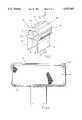
- FIG. 1is a fragmented perspective view of the present invention
- FIG. 2is a fragment front view of the seat back of a chair with the present invention applied thereon;
- FIG. 3is a cross section fragmented view of the present invention as applied to the frame of a chair along line 3--3 of FIG. 1, and;
- FIG. 4is a perspective view of an alternative embodiment of the present invention.
- edge member 10is comprised of a continuous resilient, high density resin, for example, polyvinyl chloride or polyurethane.
- Edge member 10has a pair of spaced flanges 11 and 12, respectively, disposed on opposite sides thereof and depending therefrom.
- the edge member 10is substantially annular in shape and has two cavities 14 and 15, respectively, defined by a vertically disposed, interior, stiffening rib, central chamber wall member 16.
- Chamber wall 16is contiguous with respect to the edge member 10.
- Chamber wall 16comprises a radius such that the wall top 18 and wall bottom 19 are thicker in resinous makeup than the wall center 20.
- the edge member 10is shown with a reeded finish as depicted by a number of bosses 21, however, the finish may be smooth or may incorporate other decorative looks to the taste of the user.
- FIG. 2shows the edge member 10 on the seat back 30 of a chair (shown fragmentally).
- the chamber wall 16supports the edge member 10 when edge member 10 conforms to the contour of seat back 30, such that the edge member 10 does not deflect substantially when placed on the curves of seat back 30.
- the height H of edge member 10 taken along a flat portion of seat back 30is substantially similiar to the height H' of edge member 10 taken at a curved section of the seat back 30.
- FIG. 3A cross section of the edge member 10 on seat back 30 is illustrated in FIG. 3. Therein, flanges 11 and 12 fit about the frame 31 of seat back 30. Flanges 11 and 12 depend from edge member 10 and are spaced apart by beam 32 of edge member 10. Beam 32 is generally flat and forms a flush fit to conform to the shape of seat back frame 31. As shown, seat back frame 31 is flat and thus, beam 32 is generally flat.
- Edge member 10is secured to frame 31 by staples 34 attached through flanges 11 and 12. Thereafter, upholstery 35 is added to finish the seat back 30 or other seating device. The top of the upholstery 35 is secured by staples 36 to the flange 12 (as shown), and then looped over the staple 36 so as to hide it. The bottom of the upholstery 35 is then secured to the bottom of the seat back 30 or other seating device.
- chamber wall 40divides the hollow interior of the edge member 10 into four cavities 41.
- a plurality of cavities or chamber wallsmay be designed depending upon the material chosen for the edge member 10 and the degree of flexibility sought in the member 10.
- the preferred embodimentdoes comprise at least one chamber wall and two cavities as disclosed and taught above.
Landscapes
- Chair Legs, Seat Parts, And Backrests (AREA)
Abstract
Description
Claims (17)
Priority Applications (1)
| Application Number | Priority Date | Filing Date | Title |
|---|---|---|---|
| US08/460,249US5527097A (en) | 1995-06-02 | 1995-06-02 | Edging member and seating device therefore |
Applications Claiming Priority (1)
| Application Number | Priority Date | Filing Date | Title |
|---|---|---|---|
| US08/460,249US5527097A (en) | 1995-06-02 | 1995-06-02 | Edging member and seating device therefore |
Publications (1)
| Publication Number | Publication Date |
|---|---|
| US5527097Atrue US5527097A (en) | 1996-06-18 |
Family
ID=23827939
Family Applications (1)
| Application Number | Title | Priority Date | Filing Date |
|---|---|---|---|
| US08/460,249Expired - Fee RelatedUS5527097A (en) | 1995-06-02 | 1995-06-02 | Edging member and seating device therefore |
Country Status (1)
| Country | Link |
|---|---|
| US (1) | US5527097A (en) |
Cited By (22)
| Publication number | Priority date | Publication date | Assignee | Title |
|---|---|---|---|---|
| USD413216S (en) | 1997-10-01 | 1999-08-31 | Hanco Inc. | Edge trim surface treatment for a chair |
| USD413743S (en)* | 1997-10-01 | 1999-09-14 | Hanco, Inc. | Surface treatment for the edge trim of a chair |
| GB2365327A (en)* | 2000-07-29 | 2002-02-20 | Richard Graham Kraemer | Protective edge cover for furniture |
| US6378831B1 (en)* | 2000-05-11 | 2002-04-30 | John R Copeland, Jr. | Air-guard corner and edge protector |
| USD463261S1 (en) | 2000-10-17 | 2002-09-24 | Majestic Industries, Inc. | Faceted chair bumper |
| US6564409B2 (en)* | 2000-08-01 | 2003-05-20 | Hill-Rom Services, Inc. | Bumper apparatus for a hospital bed |
| US7296312B2 (en) | 2002-09-06 | 2007-11-20 | Hill-Rom Services, Inc. | Hospital bed |
| US20080166515A1 (en)* | 2007-01-05 | 2008-07-10 | Gasser Chair Company, Inc. | Unitary molded, shaped and sized protective edge made of elastomeric material |
| US7523515B2 (en) | 1995-01-03 | 2009-04-28 | Hill-Rom Services, Inc. | Hospital bed and mattress having a retractable foot section |
| US20090239005A1 (en)* | 2006-03-27 | 2009-09-24 | Hawkins Mark P | Edge impact protector |
| US20100289319A1 (en)* | 2009-05-13 | 2010-11-18 | Michigan Tube Swagers & Fabricators, Inc. | Method of upholstering chair element |
| EP2327331A1 (en)* | 2009-11-27 | 2011-06-01 | Hopf, Hans-Jürgen | Edge protector |
| US20120187733A1 (en)* | 2011-01-26 | 2012-07-26 | Mei Chuen Lin | Mechanism For Self Folding Up And Cushing A Seat Of Portable Chair |
| US8286282B2 (en) | 1995-08-04 | 2012-10-16 | Hill-Rom Services, Inc. | Bed frame and mattress synchronous control |
| US20130134640A1 (en)* | 2011-11-29 | 2013-05-30 | Gina Thaxton | Corner and edge cushioning device, system and method of using same |
| US8973990B2 (en) | 2012-09-20 | 2015-03-10 | Steelcase Inc. | Chair assembly |
| US9009893B2 (en) | 1999-12-29 | 2015-04-21 | Hill-Rom Services, Inc. | Hospital bed |
| US9089459B2 (en) | 2013-11-18 | 2015-07-28 | Völker GmbH | Person support apparatus |
| USD742678S1 (en) | 2012-09-20 | 2015-11-10 | Steelcase Inc. | Chair assembly |
| US9565949B2 (en) | 2014-05-30 | 2017-02-14 | Steelcase Inc. | Chair upholstery attachment arrangement and method |
| USD806460S1 (en)* | 2014-11-19 | 2018-01-02 | Gasser Chair Company, Inc. | Furniture edge |
| US11070037B2 (en)* | 2018-10-12 | 2021-07-20 | International Business Machines Corporation | Multi-directional impact protection with magnitude and direction indicator |
Citations (8)
| Publication number | Priority date | Publication date | Assignee | Title |
|---|---|---|---|---|
| US3281185A (en)* | 1965-06-24 | 1966-10-25 | Miller Herman Inc | Furniture construction |
| US4106739A (en)* | 1977-05-19 | 1978-08-15 | Gasser George E | Bumper edge member for chairs |
| US4370373A (en)* | 1980-07-17 | 1983-01-25 | Burlington Industries, Inc. | Flexible edging of desks |
| DE3212568A1 (en)* | 1982-04-03 | 1983-10-13 | Daimler-Benz Ag, 7000 Stuttgart | Device for attaching the cover of a seat part |
| US4582739A (en)* | 1984-02-17 | 1986-04-15 | Rosemarie Givens | Edge and corner protective bumper |
| US4810550A (en)* | 1987-10-14 | 1989-03-07 | The Gasser Chair Company | Protective table edge |
| US4848843A (en)* | 1988-08-08 | 1989-07-18 | Omni Products International, Inc. | Multiple seat chair structure |
| US5248186A (en)* | 1992-03-27 | 1993-09-28 | Shelby Williams Industries, Inc. | Bumper edge guard for upholstered seating furniture having a core member |
- 1995
- 1995-06-02USUS08/460,249patent/US5527097A/ennot_activeExpired - Fee Related
Patent Citations (9)
| Publication number | Priority date | Publication date | Assignee | Title |
|---|---|---|---|---|
| US3281185A (en)* | 1965-06-24 | 1966-10-25 | Miller Herman Inc | Furniture construction |
| US4106739A (en)* | 1977-05-19 | 1978-08-15 | Gasser George E | Bumper edge member for chairs |
| US4106739B1 (en)* | 1977-05-19 | 1991-07-23 | E Gasser George | |
| US4370373A (en)* | 1980-07-17 | 1983-01-25 | Burlington Industries, Inc. | Flexible edging of desks |
| DE3212568A1 (en)* | 1982-04-03 | 1983-10-13 | Daimler-Benz Ag, 7000 Stuttgart | Device for attaching the cover of a seat part |
| US4582739A (en)* | 1984-02-17 | 1986-04-15 | Rosemarie Givens | Edge and corner protective bumper |
| US4810550A (en)* | 1987-10-14 | 1989-03-07 | The Gasser Chair Company | Protective table edge |
| US4848843A (en)* | 1988-08-08 | 1989-07-18 | Omni Products International, Inc. | Multiple seat chair structure |
| US5248186A (en)* | 1992-03-27 | 1993-09-28 | Shelby Williams Industries, Inc. | Bumper edge guard for upholstered seating furniture having a core member |
Cited By (38)
| Publication number | Priority date | Publication date | Assignee | Title |
|---|---|---|---|---|
| US7523515B2 (en) | 1995-01-03 | 2009-04-28 | Hill-Rom Services, Inc. | Hospital bed and mattress having a retractable foot section |
| US8286282B2 (en) | 1995-08-04 | 2012-10-16 | Hill-Rom Services, Inc. | Bed frame and mattress synchronous control |
| USD413743S (en)* | 1997-10-01 | 1999-09-14 | Hanco, Inc. | Surface treatment for the edge trim of a chair |
| USD413216S (en) | 1997-10-01 | 1999-08-31 | Hanco Inc. | Edge trim surface treatment for a chair |
| US9009893B2 (en) | 1999-12-29 | 2015-04-21 | Hill-Rom Services, Inc. | Hospital bed |
| US10251797B2 (en) | 1999-12-29 | 2019-04-09 | Hill-Rom Services, Inc. | Hospital bed |
| US6378831B1 (en)* | 2000-05-11 | 2002-04-30 | John R Copeland, Jr. | Air-guard corner and edge protector |
| GB2365327A (en)* | 2000-07-29 | 2002-02-20 | Richard Graham Kraemer | Protective edge cover for furniture |
| US6564409B2 (en)* | 2000-08-01 | 2003-05-20 | Hill-Rom Services, Inc. | Bumper apparatus for a hospital bed |
| USD463261S1 (en) | 2000-10-17 | 2002-09-24 | Majestic Industries, Inc. | Faceted chair bumper |
| US7506390B2 (en) | 2002-09-06 | 2009-03-24 | Hill-Rom Services, Inc. | Patient support apparatus having controller area network |
| US7520006B2 (en) | 2002-09-06 | 2009-04-21 | Hill-Rom Services, Inc. | Hospital bed including moveable foot portion |
| US7406731B2 (en) | 2002-09-06 | 2008-08-05 | Holl-Rom Services, Inc. | Hospital bed |
| US7669263B2 (en) | 2002-09-06 | 2010-03-02 | Hill-Rom Services, Inc. | Mattress assembly including adjustable length foot |
| US7703158B2 (en) | 2002-09-06 | 2010-04-27 | Hill-Rom Services, Inc. | Patient support apparatus having a diagnostic system |
| US7296312B2 (en) | 2002-09-06 | 2007-11-20 | Hill-Rom Services, Inc. | Hospital bed |
| USRE43532E1 (en) | 2002-09-06 | 2012-07-24 | Hill-Rom Services, Inc. | Hospital bed |
| US20090239005A1 (en)* | 2006-03-27 | 2009-09-24 | Hawkins Mark P | Edge impact protector |
| US20080166515A1 (en)* | 2007-01-05 | 2008-07-10 | Gasser Chair Company, Inc. | Unitary molded, shaped and sized protective edge made of elastomeric material |
| US7998551B2 (en) | 2007-01-05 | 2011-08-16 | Gasser Chair Company, Inc. | Unitary molded, shaped and sized protective edge made of elastomeric material |
| US8152235B2 (en)* | 2009-05-13 | 2012-04-10 | Michigan Tube Swagers & Fabricators, Inc. | Method of upholstering chair element |
| US20100289319A1 (en)* | 2009-05-13 | 2010-11-18 | Michigan Tube Swagers & Fabricators, Inc. | Method of upholstering chair element |
| EP2327331A1 (en)* | 2009-11-27 | 2011-06-01 | Hopf, Hans-Jürgen | Edge protector |
| US20120187733A1 (en)* | 2011-01-26 | 2012-07-26 | Mei Chuen Lin | Mechanism For Self Folding Up And Cushing A Seat Of Portable Chair |
| US8371645B2 (en)* | 2011-01-26 | 2013-02-12 | Mei Chuen Lin | Mechanism for self folding up and cushing a seat of portable chair |
| US20130134640A1 (en)* | 2011-11-29 | 2013-05-30 | Gina Thaxton | Corner and edge cushioning device, system and method of using same |
| USD750406S1 (en) | 2012-09-20 | 2016-03-01 | Steelcase Inc. | Chair assembly |
| US9167910B2 (en) | 2012-09-20 | 2015-10-27 | Steelcase Inc. | Chair assembly |
| USD742678S1 (en) | 2012-09-20 | 2015-11-10 | Steelcase Inc. | Chair assembly |
| US9706853B2 (en) | 2012-09-20 | 2017-07-18 | Steelcase Inc. | Chair assembly |
| US9986848B2 (en) | 2012-09-20 | 2018-06-05 | Steelcase Inc. | Chair assembly method |
| US8973990B2 (en) | 2012-09-20 | 2015-03-10 | Steelcase Inc. | Chair assembly |
| US10413083B2 (en) | 2012-09-20 | 2019-09-17 | Steelcase Inc. | Chair assembly |
| US9089459B2 (en) | 2013-11-18 | 2015-07-28 | Völker GmbH | Person support apparatus |
| US9565949B2 (en) | 2014-05-30 | 2017-02-14 | Steelcase Inc. | Chair upholstery attachment arrangement and method |
| US10441089B2 (en) | 2014-05-30 | 2019-10-15 | Steelcase Inc. | Chair upholstery attachment method |
| USD806460S1 (en)* | 2014-11-19 | 2018-01-02 | Gasser Chair Company, Inc. | Furniture edge |
| US11070037B2 (en)* | 2018-10-12 | 2021-07-20 | International Business Machines Corporation | Multi-directional impact protection with magnitude and direction indicator |
Similar Documents
| Publication | Publication Date | Title |
|---|---|---|
| US5527097A (en) | Edging member and seating device therefore | |
| US5271662A (en) | Bumper edge guard for upholstered seating furniture | |
| USD373257S (en) | Serpentine club sofa | |
| USD335969S (en) | Chair | |
| USD334318S (en) | Seat cushion | |
| USD341983S (en) | Inflatable cushion | |
| US4106739A (en) | Bumper edge member for chairs | |
| US5248186A (en) | Bumper edge guard for upholstered seating furniture having a core member | |
| USD366772S (en) | Stool | |
| USD341045S (en) | Backrest for chair | |
| USD368383S (en) | Chair | |
| USD386348S (en) | Cushion | |
| USD354629S (en) | Vehicle seat | |
| USD362562S (en) | Seat | |
| USD359431S (en) | Wire fence tightener | |
| USD360315S (en) | Rocking chair | |
| USD356705S (en) | Seat cushion | |
| USD335588S (en) | Sofa | |
| USD345868S (en) | Chair | |
| USD360771S (en) | Chair frame | |
| USD320715S (en) | Seat cushion for use in a bathtub or the like | |
| USD340592S (en) | Chair frame | |
| USD333884S (en) | Neck support cushion for a shampoo basin | |
| USD398836S (en) | Vertical fastener for reinforcing rods | |
| USD398694S (en) | Inflatable chair |
Legal Events
| Date | Code | Title | Description |
|---|---|---|---|
| AS | Assignment | Owner name:MIAMI METAL PRODUCTS, INC., FLORIDA Free format text:ASSIGNMENT OF ASSIGNORS INTEREST;ASSIGNOR:MARTIN, LEO;REEL/FRAME:007500/0344 Effective date:19950602 | |
| FPAY | Fee payment | Year of fee payment:4 | |
| AS | Assignment | Owner name:BANKBOSTON, N.A., AS ADMINISTRATIVE AGENT A NATION Free format text:SECURITY INTEREST;ASSIGNOR:POMPEII FURNITURE CO., INC. (F/N/A MIAMI METAL PRODUCTS, INC.) A FLORIDA CORP.;REEL/FRAME:010371/0207 Effective date:19990827 | |
| AS | Assignment | Owner name:FLEET CAPITAL CORPORATION, AS ADMINISTRATIVE AGENT Free format text:ASSIGNMENT OF SECURITY INTEREST;ASSIGNOR:FLEET NATIONAL BANK, AS ADMINISTRATIVE AGENT, FORMERLY BANKBOSTON, N.A., ADMINISTRATIVE AGENT;REEL/FRAME:011306/0198 Effective date:20000330 | |
| AS | Assignment | Owner name:CANADIAN IMPERIAL BANK OF COMMERCE, AS ADMINISTRAT Free format text:GRANT OF PATENT SECURITY INTEREST;ASSIGNOR:POMPEII FURNITURE CO., INC. A FLORIDA CORPORATION;REEL/FRAME:011812/0764 Effective date:20010508 Owner name:FLEET CAPITAL CORPORATION, AS ADMINISTRATION AGENT Free format text:RELEASE BY SECURED PARTY;ASSIGNOR:POMPEII FURNITURE CO., INC.;REEL/FRAME:012103/0412 Effective date:20010508 | |
| AS | Assignment | Owner name:POMPEII FURNITURE CO., INC., FLORIDA Free format text:RELEASE BY SECURED PARTY;ASSIGNOR:CANADIAN IMPERIAL BANK OF COMMERCE;REEL/FRAME:015361/0328 Effective date:20040331 | |
| LAPS | Lapse for failure to pay maintenance fees | ||
| FP | Lapsed due to failure to pay maintenance fee | Effective date:20040618 | |
| STCH | Information on status: patent discontinuation | Free format text:PATENT EXPIRED DUE TO NONPAYMENT OF MAINTENANCE FEES UNDER 37 CFR 1.362 |