US5526833A - Degreasing device particularly for optical fibers - Google Patents
Degreasing device particularly for optical fibersDownload PDFInfo
- Publication number
- US5526833A US5526833AUS08/385,953US38595395AUS5526833AUS 5526833 AUS5526833 AUS 5526833AUS 38595395 AUS38595395 AUS 38595395AUS 5526833 AUS5526833 AUS 5526833A
- Authority
- US
- United States
- Prior art keywords
- pieces
- degreased
- tank
- holes
- liquid solvent
- Prior art date
- Legal status (The legal status is an assumption and is not a legal conclusion. Google has not performed a legal analysis and makes no representation as to the accuracy of the status listed.)
- Expired - Lifetime
Links
Images


Classifications
- B—PERFORMING OPERATIONS; TRANSPORTING
- B08—CLEANING
- B08B—CLEANING IN GENERAL; PREVENTION OF FOULING IN GENERAL
- B08B3/00—Cleaning by methods involving the use or presence of liquid or steam
- B08B3/04—Cleaning involving contact with liquid
- B08B3/10—Cleaning involving contact with liquid with additional treatment of the liquid or of the object being cleaned, e.g. by heat, by electricity or by vibration
- G—PHYSICS
- G02—OPTICS
- G02B—OPTICAL ELEMENTS, SYSTEMS OR APPARATUS
- G02B6/00—Light guides; Structural details of arrangements comprising light guides and other optical elements, e.g. couplings
- G02B6/24—Coupling light guides
- G02B6/25—Preparing the ends of light guides for coupling, e.g. cutting
- G—PHYSICS
- G02—OPTICS
- G02B—OPTICAL ELEMENTS, SYSTEMS OR APPARATUS
- G02B6/00—Light guides; Structural details of arrangements comprising light guides and other optical elements, e.g. couplings
- G02B6/24—Coupling light guides
- G02B6/36—Mechanical coupling means
- G02B6/38—Mechanical coupling means having fibre to fibre mating means
- G02B6/3807—Dismountable connectors, i.e. comprising plugs
- B—PERFORMING OPERATIONS; TRANSPORTING
- B08—CLEANING
- B08B—CLEANING IN GENERAL; PREVENTION OF FOULING IN GENERAL
- B08B2240/00—Type of materials or objects being cleaned
- B08B2240/02—Optical fibers or optical fiber connectors
Definitions
- the inventionconcerns a degreasing device for degreasing pieces, particularly optical fibers of a stripped optical fiber cable.
- optical fibers of an optical fiber cableare covered with grease to protect them from moisture.
- all traces of greasemust be removed from the optical fibers to be connected or spliced.
- a piece of cloth or paper impregnated with a solvent such as de-aromatized kerosene or alcoholis wiped over the fibers to be degreased.
- a solventsuch as de-aromatized kerosene or alcohol
- this methodis feasible only for a small number of optical fibers to be degreased.
- the optical fibersmust be degreased one by one, after separating each fiber to be degreased from the other fibers, so that the degreasing operation is time-consuming and difficult, and accompanied by the risk of bending the fibers far enough to crack or break them.
- a more complex second prior art methodentails using an ultrasonic degreasing device or a degreasing device which foams a liquid solvent. These devices are more suitable for cables with several tens of fibers, and can degrease them in about ten minutes. However, both these devices require a source of electrical power and are relatively large and heavy. For this reason, they are both difficult to use on-site.
- the main object of this inventionis to provide a degreasing device which is autonomous, i.e., which does not require any source of electrical power and which is portable.
- Another object of this inventionis to provide a degreasing device which is at least as effective as the prior art degreasing devices, in particular enabling cables with several tens of optical fibers to be degreased in approximately 30 seconds.
- a degreasing devicecomprises
- a container of pressurized gashaving a gas outlet nozzle directed towards the bottom of the tank
- diffusing meanslodged substantially at the bottom of the tank for diffusing the pressurized gas being released from the container nozzle into the liquid solvent under the pieces to be degreased.
- the device according to the inventiondoes not require any source of electrical power and is easy transportable and usable on-site.
- the degreasing devicecomprises means preferably disposed above the diffusing means for holding the pressurized gas container substantially vertical with the gas outlet nozzle directed towards the tanks the tank bottom.
- the holding meanscomprises a passage communicating with the diffusing means and having an opening which is shorter than the gas outlet nozzle whereby the gas outlet nozzle abuts against an internal shoulder located within the holding means and between the opening and the passage. To release the pressurized gas all that is required is to press on the bottom of the container to push the nozzle against the shoulder.
- the diffusing meanscomprises channels having one end in common and communicating with a passage receiving pressurized gas released from the gas outlet nozzle and respective ends communicating with holes discharging under the pieces to diffuse the pressurized gas into the liquid solvent.
- the gaz releasedis therefore distributed in the solvent.
- the devicefurther comprises a cavity located between the diffusing means and the bottom of the tank to collect grease removed from the pieces.
- the diffusing meanscomprises means for supporting the pieces to be degreased and through-holes discharging into the liquid solvent under the pieces to be degreased and into the cavity for collecting the grease. The grease which settles out into the cavity is therefore completely separated from the degreased pieces and cannot pollute the latter by contact with them.
- the supporting meanscomprise a recess filled with the liquid solvent for containing the pieces to be degreased and the through-holes discharge into the bottom of the recess, or in variant the supporting means is substantially flat and the through-holes discharge via countersinks on the supporting means.
- the recess or the countersinks in the supporting meanspromote the flow of the grease towards the through-holes through which it collects in the cavity. The grease does not remain in the immediate proximity of the pieces to be degreased.
- the degreasing devicecan comprise a grille facing the through-holes for avoiding a piece to fall in the cavity.
- the deviceis intended particularly for degreasing optical fibers of an optical fiber cable.
- the solventis de-aromatized kerosene, for example.
- FIG. 1is a vertical view of a degreasing device of the invention in section on the angled line I--I in FIG. 2.
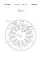
- FIG. 2is a bottom view of a first embodiment of gas diffuser included in the degreasing device of the invention.
- FIG. 3is a top view of a second embodiment of gas diffuser.
- FIG. 4is a view analogous to FIG. 1 showing the degreasing device containing optical fibers to be degreased.
- a device for degreasing piecesparticularly the end of an optical fiber cable, comprises a tank 1 with an interior fitting 2 and a container of pressurized gas in the form of a compressed gas aerosol 3.
- This deviceis easily transportable as it typically weighs only about two kilograms.
- the tank 1is cylindrical with a diameter in the order of about 20 cm and a height in the order of about 10 cm to 30 cm.
- the entire devicefeatures axial symmetry about the vertical axis YY of the tank 1.
- the tank 1is made from plastics material or metal.
- the tank 1has handles on the outside (not shown) and an airtight removable lid (not shown) to facilitate transporting the device.
- the fitting 2comprises a first member 21 in the form of a disk whose diameter is substantially equal to the inside diameter of the tank 1 and which is in the order of 5 mm thick.
- the disk 21is placed or preferably fixed by screws or locked by lugs on a circular shoulder 11 in the bottom of the tank 1, or is placed on feet (not shown) evenly distributed over the bottom 12 of the tank 1 and fixed to the bottom 12 of the tank 1 or to the bottom of the disk 21.
- a circular cavity 13is thus formed between the bottom 12 of the tank 1 and the disk 21. This cavity is separated from the remainder of the interior volume of the tank 1.
- the disk 21incorporates a plurality of through-holes 210 having a diameter in the order of five millimeters.
- the through-holes 210are equi-angularly distributed around the axis YY in order that the cavity 12 communicates with the remainder of the volume of the tank 1.
- the member 21is a grille or includes a circular or annular grille over part of its surface.
- the fitting 2comprises a second member 22 in the form of a disk whose diameter is substantially equal to the inside diameter of the tank 1 and thus equal to the diameter of the disk 21.
- the disk 22is a gas diffuser.
- the thickness of the disk 22is in the order of two centimeters to four centimeters.
- the disk 22comprises grease collecting through-holes 220 which have the same diameter as the holes 210 in the disk 21, with which they are respectively coaxial.
- the disk 22further comprises a long vertical central passage 221 discharging onto the bottom surface of the disk 22 via a circular opening 222. Channels in the form of grooves 223 on the bottom surface of the disk 22 extend radially from the periphery of the opening 222.
- each groove 223opens onto the top surface of the disk 22 through vertical gas diffusion holes 224 through the disk 22.
- each groove 223opens via one hole 224 and the holes 224 lie on a circle, for example the same circle as the holes 220.
- the holes 224 and the holes 220alternate in a regular manner, with two holes 224 for each hole 220.
- each groove 223opens through more than one hole 224 or the holes 224 lie on a circle whose diameter is less than the circle on which the holes 220 lie, for example, or the holes 224 lie on more than one circle.
- the grooves 223 and the opening 222are replaced by passages in the disk 22 connecting the central passage 221 to the holes 224, and the gas diffusion holes 221 and 224 open only onto the top surface of the disk 22. This variant is particularly advantageous if the member 21 is a grille.
- the top surface of the second disk 22is a support for the optical fibers to be degreased and incorporates a semicircular radial section annular recess 225 which forms a circular rim 226 at the perimeter of the disk 22.
- the holes 220 and 224open into the bottom of the recess 225.
- the second disk 22is placed in the tank 1 on top of the first disk 21 so that the holes 210 and 220 are aligned with each other.
- a mortice and tenon arrangementlocates the disk 22 relative to the disk 21.
- the disks 21 and 22are preferably glued or screwed together as indicated at 227 in FIG. 2.
- a second embodiment of the gas diffuser 22adiffers from the first diffuser 22 in the following respects.
- the diffuser 22ais a disk whose diameter is substantially equal to the inside diameter of the tank 1 and comprises a central through-passage 221a discharging onto the bottom surface of the disk 22a via a circular opening 222a from the periphery of which extend radial grooves 223a. The latter end at vertical gas diffusion through-holes 224a which lie on three concentric circles.
- the disk 22acomprises grease collecting through-holes 220a similar to the holes 220 previously described.
- the disk 22ahas no annular recess on its upper surface, which is substantially plane.
- Each hole 220aopens via a countersink or a spot facing 225a on the top surface of the disk 22a.
- the disk 22a shown in FIG. 3has twelve grease collecting holes 220a and thirty six gas diffusion holes 224a.
- the fitting 2comprises a third member 23 which is a receptacle adapted to receive the pressurized gas container 3.
- the latteris a commercially available compressed gas aerosol which is cylindrical in shape and has a spray nozzle 31.
- the gas in the aerosol 3is preferably a dry neutral gas such as compressed air.
- the shape of the receptacle 23matches the shape of the top of the aerosol and the receptacle includes a cylindrical bore 230 whose diameter is substantially equal to the diameter of the compressed air aerosol 3.
- the bottom of the bore 230is formed by a conical shoulder with a central passage 231 with an opening such as a cylindrical spot facing 232 with substantially the same diameter as the nozzle 31 of the aerosol 3 and a length less than that of the nozzle 31.
- the receptacle 23is coaxial with the disk 22 and the central passages 221 and 231 are therefore aligned.
- the inside diameter of the annular recess 225 in the disk 22is substantially equal to the outside diameter of the receptacle 23 and more than twice the minimal radius of curvature that can be imposed on the optical fibers without risk of cracking or breaking them.
- the receptacle 23is glued or screwed to the disk 22.
- the receptacle 23 and the disk 22are molded or machined in one piece.
- the receptacle 23 and the disk 22are demountably joined together by a mortice and tenon arrangement.
- the compressed air aerosol 3is accommodated vertically in the receptacle 23 in order that the atomizer nozzle 31 is at the bottom, facing towards the bottom 12 of the tank, and bearing on the shoulder between the spot facing 232 and the hole 231.
- the receptacle 23 and the aerosol 3are located on one side of the tank 1 rather than at the center of the tank 1.
- the operation of the degreasing deviceis described with reference to FIG. 4.
- the devicecomprises the assembled members previously described and the tank 1 contains a liquid solvent 5 to a depth such that the top surface of the disk 22 or 22a is below the surface, with the result that the solvent fills the cavity 13 and part of the upper volume of the tank 1.
- the liquid solventis de-aromatized gasolene or de-aromatized kerosene, for example, which is particularly suitable for degreasing optical fibers.
- Other solventscan be used, for example trichlorethylene, a solvent comprising an isotropic mixture of de-aromatized hydrocarbons, or an alcohol-based solvent.
- An optical fiber cable 6comprises a grooved elastic material extruded rod.
- the rodcoats a central strength member such as a steel wire which reinforces the cable to prevent mechanical stresses on the optical fibers.
- the rodcomprises helical grooves on the outside of the rod. Each helical groove contains at least one optical fiber 61.
- the cablecomprises 36, 60 or 120 optical fibers, for example.
- a filler materialcovers the optical fibers to protect them from moisture and mechanical stresses.
- the filler materialis a silicone or hydrocarbon grease.
- the optical fiber cablecomprises extruded plastics tubes twisted up around a central strength member.
- Each tubecontains optical fibers covered with grease.
- the cablecomprises a tubular protective jacket in which are disposed optical fibers covered with grease.
- an operatorfirst strips the optical fiber cable 6 at one end of the cable to a distance between a few tens of centimeters and two meters, to produce a "ponytail" of 36, 60 or 120 optical fibers, for example.
- the fibers covered with greasemust be degreased before splicing or connecting them.
- optical fibers 61 from the stripped cable 6are inserted into the device through the opening at the top of the tank 1 so that they are immersed in the liquid solvent 5 and coiled in the annular recess 225 and around the receptacle 23.
- the aerosol 3is depressed by hand so that the atomizer nozzle 31 is pressed onto the small shoulder between the spot facing 232 and the hole 231, and draws back into the aerosol 3 to open a valve which releases pressurized gas from the aerosol. Because the aerosol 3 is inverted as compared to its usual position of use, i.e. because the spray nozzle of the aerosol 3 is at the bottom, the gas dispensed from the aerosol is at a low temperature.
- the expanding gasflows in succession through the passages 231 and 221 and is then distributed via the circular recess 222 into the grooves 223 before diffusing via the holes 224 into the solvent 5 below the optical fibers 61. Because the holes 224 are evenly distributed on the disk 22 the gas is diffused into all of the volume of solvent in which the optical fibers are immersed.
- the cold gascauses turbulence in the liquid solvent.
- the grease on the optical fiberscongeals and loses its adhesive properties.
- the solvent decantsowing to the turbulence in the cooled solvent which detaches the grease from the optical fibers.
- the greasethen drops to the bottom of the recess 225 and passes into the cavity 13 through the holes 210 and 220.
- the annular recess 225 or the countersinks 225apromote flow of the grease towards the holes 210 and 220.
- the "ponytail" of optical fibersis completely degreased in about 30 seconds, and this requires no input of electrical power.
- the inventionhas been described with reference to degreasing optical fibers.
- the axial symmetry of the deviceis well suited to flexible filamentary pieces in order to reduce the overall size of the device.
- the tank 1 and the members 21, 22, 23can be long and rectangular, for example.
- the inventionapplies to any type of piece on which grease or oil is deposited.
- mechanical partssuch as ball bearings, motor drive chains, screws and any other parts which are difficult to degrease because of their complicated surface are perfectly degreased using the degreasing device of the invention.
Landscapes
- Physics & Mathematics (AREA)
- General Physics & Mathematics (AREA)
- Optics & Photonics (AREA)
- Cleaning By Liquid Or Steam (AREA)
Abstract
Description
Claims (11)
Applications Claiming Priority (2)
| Application Number | Priority Date | Filing Date | Title |
|---|---|---|---|
| FR9401673 | 1994-02-11 | ||
| FR9401673AFR2716267B1 (en) | 1994-02-11 | 1994-02-11 | Degreasing device especially for optical fibers. |
Publications (1)
| Publication Number | Publication Date |
|---|---|
| US5526833Atrue US5526833A (en) | 1996-06-18 |
Family
ID=9460070
Family Applications (1)
| Application Number | Title | Priority Date | Filing Date |
|---|---|---|---|
| US08/385,953Expired - LifetimeUS5526833A (en) | 1994-02-11 | 1995-02-09 | Degreasing device particularly for optical fibers |
Country Status (4)
| Country | Link |
|---|---|
| US (1) | US5526833A (en) |
| EP (1) | EP0667191B1 (en) |
| DE (1) | DE69500964T2 (en) |
| FR (1) | FR2716267B1 (en) |
Cited By (12)
| Publication number | Priority date | Publication date | Assignee | Title |
|---|---|---|---|---|
| US6085763A (en)* | 1998-11-06 | 2000-07-11 | Telefonaktiebolaget Lm Ericsson | Rinsing bath |
| US6402856B1 (en)* | 2000-11-28 | 2002-06-11 | 3Sae Technologies, Inc. | Method and apparatus for stripping an optical fiber |
| US6607608B1 (en) | 2000-11-28 | 2003-08-19 | 3Sae Technologies, Inc. | Translatable fiber stripper |
| US6676763B2 (en)* | 2001-07-06 | 2004-01-13 | Ksaira Corporation | Method and apparatus for cleaning an optical fiber |
| US20040079390A1 (en)* | 2001-07-20 | 2004-04-29 | Wiley Robert G. | Multi-step fiber stripping |
| WO2003018216A3 (en)* | 2001-08-21 | 2004-05-13 | Capewell Components Company Ll | Cleaning apparatus and method of cleaning using an ultrasonically excited cleaning fluid |
| US20050166944A1 (en)* | 2004-01-30 | 2005-08-04 | Daw-Ming Fann | Cascade extracting and solvent refreshing method for recycling jelly cables |
| EP1540399A4 (en)* | 2002-07-18 | 2005-10-19 | Westover Scient Inc | Fiber-optic endface cleaning apparatus and method |
| US20110044600A1 (en)* | 2007-09-25 | 2011-02-24 | Ksaria Corporation | Apparatus for shaping the end of an optical fiber |
| US8254738B2 (en) | 2010-08-27 | 2012-08-28 | Ksaria Corporation | Methods and systems for efficient installation of cables in watercraft |
| US8763983B2 (en) | 2010-03-31 | 2014-07-01 | Safoco, Inc. | Safety valve and method of use |
| US9239428B2 (en) | 2011-09-28 | 2016-01-19 | Ksaria Corporation | Epoxy dispensing system and dispensing tip used therewith |
Citations (9)
| Publication number | Priority date | Publication date | Assignee | Title |
|---|---|---|---|---|
| GB627888A (en)* | 1945-10-29 | 1949-08-17 | Tage Edvard Hjalmar Bahrton | A device for dish washing in a dish washing sink |
| US2559472A (en)* | 1947-10-30 | 1951-07-03 | Charles B Shanaman | Pneumatic actuating means for metal parts washers |
| US2720210A (en)* | 1953-02-26 | 1955-10-11 | Chester G Lueck | Parts cleaner |
| GB961591A (en)* | 1961-04-10 | 1964-06-24 | George Thomas Church | A method of and device for cleaning eggs |
| US3259049A (en)* | 1962-12-14 | 1966-07-05 | V & A Plating Supplies Inc | Gas agitating device |
| US4080975A (en)* | 1976-12-09 | 1978-03-28 | Williams Jr Samuel R H | Heated and air injected tank for parts cleaner |
| US4852596A (en)* | 1987-05-08 | 1989-08-01 | The University Of Virginia Alumni Patents Foundation | Micro slide irrigating unit |
| US4967777A (en)* | 1988-07-29 | 1990-11-06 | Texas Instruments Incorporated | Apparatus for treating substrates with a liquid |
| US5014727A (en)* | 1989-02-27 | 1991-05-14 | Seiichiro Aigo | Bubbler device for washing semiconductor materials |
Family Cites Families (4)
| Publication number | Priority date | Publication date | Assignee | Title |
|---|---|---|---|---|
| DE3010594A1 (en)* | 1980-03-19 | 1981-09-24 | Siemens AG, 1000 Berlin und 8000 München | DEVICE FOR PARTIAL PAINTING OF LIGHT-WAVE GUIDES |
| DE3341919C1 (en)* | 1983-11-19 | 1985-01-17 | ANT Nachrichtentechnik GmbH, 7150 Backnang | Arrangement for cleaning optical fibres having primary protection |
| DE3715332A1 (en)* | 1987-05-08 | 1988-12-01 | Bielefeld Maschinenbau Gmbh | METHOD AND DEVICE FOR CLEANING WORKPIECES |
| SU1733127A1 (en)* | 1989-12-22 | 1992-05-15 | Северо-Кавказский Филиал Государственного Всесоюзного Научно-Исследовательского Института Ремонта И Эксплуатации Машинно-Тракторного Парка | Workpiece cleaning arrangement |
- 1994
- 1994-02-11FRFR9401673Apatent/FR2716267B1/ennot_activeExpired - Fee Related
- 1995
- 1995-02-03EPEP95400232Apatent/EP0667191B1/ennot_activeExpired - Lifetime
- 1995-02-03DEDE69500964Tpatent/DE69500964T2/ennot_activeExpired - Lifetime
- 1995-02-09USUS08/385,953patent/US5526833A/ennot_activeExpired - Lifetime
Patent Citations (9)
| Publication number | Priority date | Publication date | Assignee | Title |
|---|---|---|---|---|
| GB627888A (en)* | 1945-10-29 | 1949-08-17 | Tage Edvard Hjalmar Bahrton | A device for dish washing in a dish washing sink |
| US2559472A (en)* | 1947-10-30 | 1951-07-03 | Charles B Shanaman | Pneumatic actuating means for metal parts washers |
| US2720210A (en)* | 1953-02-26 | 1955-10-11 | Chester G Lueck | Parts cleaner |
| GB961591A (en)* | 1961-04-10 | 1964-06-24 | George Thomas Church | A method of and device for cleaning eggs |
| US3259049A (en)* | 1962-12-14 | 1966-07-05 | V & A Plating Supplies Inc | Gas agitating device |
| US4080975A (en)* | 1976-12-09 | 1978-03-28 | Williams Jr Samuel R H | Heated and air injected tank for parts cleaner |
| US4852596A (en)* | 1987-05-08 | 1989-08-01 | The University Of Virginia Alumni Patents Foundation | Micro slide irrigating unit |
| US4967777A (en)* | 1988-07-29 | 1990-11-06 | Texas Instruments Incorporated | Apparatus for treating substrates with a liquid |
| US5014727A (en)* | 1989-02-27 | 1991-05-14 | Seiichiro Aigo | Bubbler device for washing semiconductor materials |
Cited By (17)
| Publication number | Priority date | Publication date | Assignee | Title |
|---|---|---|---|---|
| US6085763A (en)* | 1998-11-06 | 2000-07-11 | Telefonaktiebolaget Lm Ericsson | Rinsing bath |
| US6402856B1 (en)* | 2000-11-28 | 2002-06-11 | 3Sae Technologies, Inc. | Method and apparatus for stripping an optical fiber |
| US6607608B1 (en) | 2000-11-28 | 2003-08-19 | 3Sae Technologies, Inc. | Translatable fiber stripper |
| US6676763B2 (en)* | 2001-07-06 | 2004-01-13 | Ksaira Corporation | Method and apparatus for cleaning an optical fiber |
| US20040079390A1 (en)* | 2001-07-20 | 2004-04-29 | Wiley Robert G. | Multi-step fiber stripping |
| US6799383B2 (en) | 2001-07-20 | 2004-10-05 | 3Sae Technologies, Inc. | Multi-step fiber stripping |
| WO2003018216A3 (en)* | 2001-08-21 | 2004-05-13 | Capewell Components Company Ll | Cleaning apparatus and method of cleaning using an ultrasonically excited cleaning fluid |
| EP1540399A4 (en)* | 2002-07-18 | 2005-10-19 | Westover Scient Inc | Fiber-optic endface cleaning apparatus and method |
| US20050166944A1 (en)* | 2004-01-30 | 2005-08-04 | Daw-Ming Fann | Cascade extracting and solvent refreshing method for recycling jelly cables |
| US7011713B2 (en)* | 2004-01-30 | 2006-03-14 | Chunghwa Telecom Co., Ltd. | Cascade extracting and solvent refreshing method for recycling jelly cables |
| US20110044600A1 (en)* | 2007-09-25 | 2011-02-24 | Ksaria Corporation | Apparatus for shaping the end of an optical fiber |
| US8406598B2 (en) | 2007-09-25 | 2013-03-26 | Ksaria Corporation | Apparatus for shaping the end of an optical fiber |
| US8763983B2 (en) | 2010-03-31 | 2014-07-01 | Safoco, Inc. | Safety valve and method of use |
| US8254738B2 (en) | 2010-08-27 | 2012-08-28 | Ksaria Corporation | Methods and systems for efficient installation of cables in watercraft |
| US8478096B2 (en) | 2010-08-27 | 2013-07-02 | Ksaria Corporation | Methods and systems for efficient installation of cables in watercraft |
| US8577194B2 (en) | 2010-08-27 | 2013-11-05 | Ksaria Corporation | Methods and systems for efficient installation of cables in watercraft |
| US9239428B2 (en) | 2011-09-28 | 2016-01-19 | Ksaria Corporation | Epoxy dispensing system and dispensing tip used therewith |
Also Published As
| Publication number | Publication date |
|---|---|
| EP0667191A1 (en) | 1995-08-16 |
| FR2716267B1 (en) | 1996-03-22 |
| DE69500964T2 (en) | 1998-03-19 |
| EP0667191B1 (en) | 1997-11-05 |
| FR2716267A1 (en) | 1995-08-18 |
| DE69500964D1 (en) | 1997-12-11 |
Similar Documents
| Publication | Publication Date | Title |
|---|---|---|
| US5526833A (en) | Degreasing device particularly for optical fibers | |
| EP0849584A3 (en) | Apparatus (cuvette) for receiving and storing liquids and for performing optical measurements | |
| JPS6433205A (en) | Leak testing method apparatus | |
| US5873500A (en) | Fluid delivery cart | |
| US20050105859A1 (en) | Fiber-optic endface cleaning assembly and method | |
| IE50394B1 (en) | Simultaneous analysis apparatus | |
| US5707861A (en) | Disintegrator of living cells | |
| BR9306422A (en) | Apparatus for pulling test fluid sample into container reusable slide set for analysis with microscope Apparatus for pulling test fluid sample through slide set | |
| US6083462A (en) | Specimen identifier | |
| US4787827A (en) | Portable lubricating apparatus | |
| EP0287164A1 (en) | Movable beer dispenser | |
| US4859262A (en) | Method of making storage tanks with secondary containment | |
| JPS6052743A (en) | Observing cell for fractional distillation of liquid sample | |
| US20090320566A1 (en) | Systems and Methods for Monitoring the Integrity of a Tank | |
| US4913310A (en) | Storage tanks with secondary containment | |
| EP0082263A1 (en) | Sample introduction for chemical analysis by spectrometry/liquid chromatography | |
| US7131450B2 (en) | Method for washing a sample tube and its washing apparatus | |
| CA1186247A (en) | Pressure filter adaptor and containment vessel | |
| CN211925402U (en) | Electric temperature control leakage-proof gas drainer | |
| US2519572A (en) | Sealing closure means for converters | |
| CN211423809U (en) | Display device for video intelligent identification | |
| Le Floc'h et al. | Acoustic Emission Applied to Observe Damage in Composite Material High-Pressure Fluid Storage Tanks.(Retroactive Coverage) | |
| US3436957A (en) | Oil well tubing testing and cleaning apparatus | |
| US6407356B1 (en) | Electrical discharge machining device | |
| JP2604789Y2 (en) | Oil injector nozzle |
Legal Events
| Date | Code | Title | Description |
|---|---|---|---|
| AS | Assignment | Owner name:FRANCE TELECOM, FRANCE Free format text:ASSIGNMENT OF ASSIGNORS INTEREST;ASSIGNORS:CRESPEL, DANIEL;CAILLEAUX, JEAN-MARC;CAUDRELIER, JACQUES;REEL/FRAME:007485/0168 Effective date:19950223 | |
| STCF | Information on status: patent grant | Free format text:PATENTED CASE | |
| FEPP | Fee payment procedure | Free format text:PAYOR NUMBER ASSIGNED (ORIGINAL EVENT CODE: ASPN); ENTITY STATUS OF PATENT OWNER: LARGE ENTITY | |
| FPAY | Fee payment | Year of fee payment:4 | |
| FPAY | Fee payment | Year of fee payment:8 | |
| AS | Assignment | Owner name:FAHRENHEIT THERMOSCOPE LLC, NEVADA Free format text:ASSIGNMENT OF ASSIGNORS INTEREST;ASSIGNOR:FRANCE TELECOM S.A.;REEL/FRAME:016087/0850 Effective date:20041203 | |
| AS | Assignment | Owner name:FAHRENHEIT THERMOSCOPE, LLC, NEVADA Free format text:ASSIGNMENT OF ASSIGNORS INTEREST;ASSIGNOR:FRANCE TELECOM INC.;REEL/FRAME:018022/0941 Effective date:20041203 | |
| FPAY | Fee payment | Year of fee payment:12 | |
| FEPP | Fee payment procedure | Free format text:PAYER NUMBER DE-ASSIGNED (ORIGINAL EVENT CODE: RMPN); ENTITY STATUS OF PATENT OWNER: LARGE ENTITY Free format text:PAYOR NUMBER ASSIGNED (ORIGINAL EVENT CODE: ASPN); ENTITY STATUS OF PATENT OWNER: LARGE ENTITY | |
| AS | Assignment | Owner name:FAHRENHEIT THERMOSCOPE LLC, NEVADA Free format text:CORRECTIVE ASSIGNMENT TO CORRECT THE ASSIGNOR NAME PREVIOUSLY RECORDED ON REEL 018022 FRAME 0941. ASSIGNOR(S) HEREBY CONFIRMS THE ASSIGNOR NAME IS FRANCE TELECOM S.A., NOT FRANCE TELECOM INC;ASSIGNOR:FRANCE TELECOM S.A.;REEL/FRAME:024723/0847 Effective date:20041203 |