US5526041A - Rail-based closed circuit T.V. surveillance system with automatic target acquisition - Google Patents
Rail-based closed circuit T.V. surveillance system with automatic target acquisitionDownload PDFInfo
- Publication number
- US5526041A US5526041AUS08/302,341US30234194AUS5526041AUS 5526041 AUS5526041 AUS 5526041AUS 30234194 AUS30234194 AUS 30234194AUS 5526041 AUS5526041 AUS 5526041A
- Authority
- US
- United States
- Prior art keywords
- camera
- carriage
- target object
- along
- positions
- Prior art date
- Legal status (The legal status is an assumption and is not a legal conclusion. Google has not performed a legal analysis and makes no representation as to the accuracy of the status listed.)
- Expired - Lifetime
Links
Images


Classifications
- G—PHYSICS
- G08—SIGNALLING
- G08B—SIGNALLING OR CALLING SYSTEMS; ORDER TELEGRAPHS; ALARM SYSTEMS
- G08B13/00—Burglar, theft or intruder alarms
- G08B13/18—Actuation by interference with heat, light, or radiation of shorter wavelength; Actuation by intruding sources of heat, light, or radiation of shorter wavelength
- G08B13/189—Actuation by interference with heat, light, or radiation of shorter wavelength; Actuation by intruding sources of heat, light, or radiation of shorter wavelength using passive radiation detection systems
- G08B13/194—Actuation by interference with heat, light, or radiation of shorter wavelength; Actuation by intruding sources of heat, light, or radiation of shorter wavelength using passive radiation detection systems using image scanning and comparing systems
- G08B13/196—Actuation by interference with heat, light, or radiation of shorter wavelength; Actuation by intruding sources of heat, light, or radiation of shorter wavelength using passive radiation detection systems using image scanning and comparing systems using television cameras
- G08B13/19678—User interface
- G08B13/19689—Remote control of cameras, e.g. remote orientation or image zooming control for a PTZ camera
- G—PHYSICS
- G08—SIGNALLING
- G08B—SIGNALLING OR CALLING SYSTEMS; ORDER TELEGRAPHS; ALARM SYSTEMS
- G08B13/00—Burglar, theft or intruder alarms
- G08B13/18—Actuation by interference with heat, light, or radiation of shorter wavelength; Actuation by intruding sources of heat, light, or radiation of shorter wavelength
- G08B13/189—Actuation by interference with heat, light, or radiation of shorter wavelength; Actuation by intruding sources of heat, light, or radiation of shorter wavelength using passive radiation detection systems
- G08B13/194—Actuation by interference with heat, light, or radiation of shorter wavelength; Actuation by intruding sources of heat, light, or radiation of shorter wavelength using passive radiation detection systems using image scanning and comparing systems
- G08B13/196—Actuation by interference with heat, light, or radiation of shorter wavelength; Actuation by intruding sources of heat, light, or radiation of shorter wavelength using passive radiation detection systems using image scanning and comparing systems using television cameras
- G08B13/19617—Surveillance camera constructional details
- G08B13/19623—Arrangements allowing camera linear motion, e.g. camera moving along a rail cable or track
- G—PHYSICS
- G08—SIGNALLING
- G08B—SIGNALLING OR CALLING SYSTEMS; ORDER TELEGRAPHS; ALARM SYSTEMS
- G08B13/00—Burglar, theft or intruder alarms
- G08B13/18—Actuation by interference with heat, light, or radiation of shorter wavelength; Actuation by intruding sources of heat, light, or radiation of shorter wavelength
- G08B13/189—Actuation by interference with heat, light, or radiation of shorter wavelength; Actuation by intruding sources of heat, light, or radiation of shorter wavelength using passive radiation detection systems
- G08B13/194—Actuation by interference with heat, light, or radiation of shorter wavelength; Actuation by intruding sources of heat, light, or radiation of shorter wavelength using passive radiation detection systems using image scanning and comparing systems
- G08B13/196—Actuation by interference with heat, light, or radiation of shorter wavelength; Actuation by intruding sources of heat, light, or radiation of shorter wavelength using passive radiation detection systems using image scanning and comparing systems using television cameras
- G08B13/19678—User interface
- G08B13/1968—Interfaces for setting up or customising the system
Definitions
- This inventionrelates generally to closed-circuit television surveillance systems and pertains more particularly to such systems in which a television camera is mounted on a carriage for movement along a rail or track, and in which the system is subject to automatic control by a computer or the like.
- a target objectsuch as a door
- a sensorwhich provides an alarm signal to a central control portion of the surveillance system when the door is opened.
- the control systemcan implement an immediate adjustment to the camera direction, zoom condition, etc. so that an image of the door is provided by the camera within a very short time after the door is opened.
- the systemutilizes a moving camera, such as a camera mounted on a carriage which travels along a rail
- the cameramay be located at any arbitrary position in its range of movement at the time an alarm is received. Since the camera location at the time of the alarm cannot be known in advance, it is not possible to store in advance data defining a particular direction and zoom condition of the camera which will enable the camera to provide an image of the target from the position of the camera at the time of the alarm.
- the human operatormay attempt to respond to the alarm signal by operating system controls to reposition the camera carriage and to adjust the camera direction, etc. so that an image of the target object is obtained.
- the variety of possible camera positions and directions-of-viewmay lead to disorientation on the part of the operator.
- the systemis set up with multiple target objects (e.g., multiple doors, windows, cabinets and so forth) for which alarms may be actuated, the operator may have difficulty identifying the particular target to which the alarm pertains. As a result, the human operator's response to the alarm may be too slow to capture an image of the event (such as entry of an intruder) which caused the alarm.
- the present intentionhas as its primary object the provision of a closed circuit television surveillance system, using a rail-based television camera, that is capable of acquiring an image of a fixed target within a minimum amount of time after receipt of an alarm signal or the like.
- Another object of the inventionis provision of a surveillance system using a rail-mounted camera in which the camera is controlled to continuously track a target while the camera is moving along the rail.
- the inventionprovides a method of operating a rail-based closed-circuit television surveillance system wherein the system includes an elongated track positioned along a path, a carriage supported and movable along the track for transporting a television camera along the path, carriage moving means coupled to the carriage for selectively moving the carriage along the track, camera control means for selectively adjusting a direction of view and a zoom condition of the television camera, and carriage control means for selectively positioning the carriage along the track, and wherein the method includes the steps of initializing the system by capturing an image of a predetermined target object by means of the television camera at respective times when the camera is at two different selected points along the track and storing initialization data indicative of the selected points and the respective directions of view of the camera used for capturing the target object image at the selected points; calculating from the stored initialization data an optimum viewpoint along the track for capturing an image of the predetermined target object and an optimum pan angle, an optimum tilt angle and an optimum zoom condition for capturing the image of the
- the direction of view of the camerais continuously adjusted while the carriage is moved from one of the two selected points to the optimum point so that the direction of view of-the camera remains oriented towards the target object during the movement of the carriage from the one of the two selected points to the optimum point.
- the optimum viewpointbe between the selected points used during initialization and that the optimum viewpoint be the closest point along the track to the target object.
- the carriageis moved toward the closer of the two points and the direction of view of the camera is adjusted, while the carriage is being moved toward the closer of the two selected points, so that the camera has the same direction of view that was used during the initialization to capture the image of the predetermined target object from the closer of the two selected points.
- the carriagebe reciprocated between the two selected points in response to the target acquisition signal and that the direction of view of the camera be continuously adjusted so that the direction of view of the camera remains oriented towards the target object during the reciprocating movement of the carriage.
- FIG. 1is a perspective view of a closed-circuit television surveillance system, using a rail mounted camera, in which the present invention may be applied.
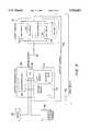
- FIG. 2is a block diagram of a surveillance system in accordance with the invention.
- FIGS. 3A and 3Bare respectively top and back isometric schematic diagrams used for explaining initialization and automatic target acquisition procedures carried out in accordance with the invention.
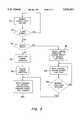
- FIG. 4is a flow chart of an initialization routine carried out in accordance with the invention.
- FIG. 5is a flow chart of a routine carried out in accordance with the invention for automatically acquiring a target in response to an alarm signal.
- FIG. 1shows the interior of a building in which there is installed a surveillance system in accordance with the present invention.
- the systemincludes a surveillance camera 10 that is mounted on a carriage 12.
- the carriage 12is movably supported on an elongated track or rail 14, which is suspended from the ceiling 16 of the building.
- the camera 10may be of a conventional type which is subject to remote control as to the direction in which the camera is oriented.
- the camerais controllable for horizontal pivoting movement, known as “panning”, as well as vertical pivoting movement known as “tilting”.
- a motorized mirror assemblymay be mounted on the carriage in association with the camera 10 for accomplishing tilting and panning adjustments of the direction of view of the camera.
- the carriage 12includes a motor 18 which is also subject to remote control by the surveillance system.
- Appropriate encodingsuch as optical encoding (not shown) is provided along the rail 14 so that the position of the carriage 12 along the rail can be sensed and an appropriate carriage position signal provided to the control system.
- other techniquesmay be employed to determine the position of the carriage, such as detecting operation of motor 18.
- the carriagecan be controllably moved to desired positions along the rail 14.
- connections for controlling the camera 10 and the carriage 12can be via cable (in which case a cable reel carriage may be provided integrated with or separate from camera carriage 12) or by wireless communication links.
- an opaque cover or the like for hiding the camera 10may be provided surrounding the rail 14 and the path of travel of the carriage 12.
- the building interior shown in FIG. 1includes a door 20 located at the end of an aisle 22 formed between racks or tiers 24 of merchandise or the like.
- a sensor 26is installed in proximity to the door 20 and provides an alarm signal when, for example, the door is opened.
- FIG. 2illustrates the surveillance system of the present invention in block diagram form.
- a central processing unit (CPU) 28which includes a microprocessor 30.
- a program memory 32for storing control software
- a data memory 34in which working data are stored, including, as will be seen, parameter data collected during an initialization routine.
- CPU 28also includes an input/output (I/O) module 36 which is connected to microprocessor 30 and provides an interface between the CPU 28 and other portions of the surveillance system.
- I/Oinput/output
- I/O module 36is connected by way of a signal path 37 to a pan motor 38, a tilt motor 40, a zoom motor 42 and a rail motor 44.
- Pan motor 38provides the above-mentioned panning adjustments for the video camera 10
- tilt motor 40provides the above-mentioned tilt adjustments of the video camera 10
- zoom motor 42implements changes in the zoom condition of the camera 10
- rail or carriage motor 44propels the carriage 12 along the rail 14.
- Each of these motorsreceives control signals from the CPU 28 by way of the I/O module 36 and the signal path 37, and all of these motors are carried on the carriage 12 (although, as an alternative, the carriage 12 may be driven by an off-board motor through a belt drive or the like).
- each of the motors 38, 40, 42, and 44are arranged to provide position feedback signals indicative of the position of the motor or of the carriage, as the case may be. These signals are transmitted back to the CPU 28 by way of a signal path 46 and I/O module 36.
- the paths 37 and 46may, for example, be embodied by appropriate cabling, or wireless data channels, etc.
- I/O module 36Also connected to CPU 28 by way of I/O module 36 are a user terminal 48 and the above-mentioned sensor 26.
- the terminal 48permits a human operator to input data to the CPU 28 in a conventional manner, and also permits the CPU 28 to display data to the human operator in a conventional manner.
- the I/O module 36is provided with a communication channel from the sensor 26 for receiving therefrom the above-mentioned alarm signal, upon opening of the door 20 (FIG. 1).
- the surveillance system shown in FIG. 2provides the customary capabilities for remote control of the camera 10 and carriage 12 by the human operator, including selective positioning of the carriage 12, and panning, tilting and zooming of the camera 10, all by way of signals input via the terminal 48.
- the surveillance systemalso includes a video display monitor 49 connected (or linked by wireless channel) to receive and display the video output signal provided by the camera 10.
- display 49is shown as being separate from terminal 48, it is also contemplated to share a monitor portion of terminal 48 with display 49, by means of split screen, windowing, time sharing, superposition of a cursor and characters on the video display, and so forth.
- the rail 14, door 20 and merchandise tiers 24are positioned with respect to each other so that the door 20 is within a line of sight of the camera 10 over a portion of the rail 12, but when the carriage 12 is positioned outside of that portion of the rail 14, the line of sight from the camera 10 to the door 20 is occluded by, for example, the tiers of merchandise 24.
- the door 20is a target for which automatic image acquisition is desired. Accordingly, there will first be described an initialization procedure during which appropriate data is stored in the CPU 28 to allow for an automatic target acquisition operation in accordance with the invention.
- FIGS. 3A and 3Bare respectively top and back diagrammatic views which illustrate geometric relationships among a target (assumed to be door 20), the rail 14 (taken to be the "z-axis"), and various positions along rail 14 at which the carriage 12 may be located.
- the x-axis directionis taken to be the horizontal direction perpendicular to the rail 14, and the y-axis direction is taken to be the vertical direction.
- the horizontal plane which passes through the rail 14will be referred to as the x-z plane, while the vertical plane which passes through rail 14 will be referred to as the y-z plane.
- Point R1corresponds to a right-most position on the rail 14 from which there is a line of sight to the target door 20, and point R2 corresponds to the left-most position on the rail 14 from which there is a line of sight to the target door 20.
- a zero-reference or origin pointis taken to be at a leftward position along the rail(z-axis), so that the position index of R1 is larger than the position index of R2.
- point Rnrepresents a position on the rail 14 that is closest to the target 20, and Rz indicates an arbitrary position between points R2 and R1 at which the carriage 12 and camera 10 may be located at any given time.
- the systemis arranged so that the camera 12 may at some times be at positions along rail 14 that are outside of the range defined between point R2 and R1.
- the line B1represents the projection on the x-z plane of the line of sight from point R1 to the target
- the line B2represents the projection on the x-z plane of the line of sight from point R2 to the target.
- the dashed line Bzsimilarly represents the projection on the x-z plane of the line of sight from the arbitrary point Rz to the target
- the dotted line Nrepresents the projection on the x-z plane of the line of sight from the point Rn to the target.
- the line segment A2is defined between the points R2 and Rn, and the line segment A1 is defined between points Rn and R1.
- the line segment A12is defined between the points Rn and Rz.
- the point Txzis located in the x-z plane directly above the target.
- the angle ⁇ 1 between line B1 and the z axisrepresents the required pan angle for the camera to acquire the target when the carriage is located at point R1
- the angle ⁇ 2 between the line B2 and the z axisrepresents the appropriate pan angle for the camera to acquire the target when the carriage is located at the point R2.
- the angle ⁇ z formed between the line Bz and the z axisrepresents the appropriate pan angle for acquiring the target when the camera is located at point R z ,
- FIG. 3Bwill indicate that the appropriate camera tilt angles for target acquisition from points R2, Rz and R1 are schematically represented by the angles ⁇ 2, ⁇ z and ⁇ 1.
- the line Dzrepresents the line of sight from point Rz to the target (not a projection)
- the dotted line Yis the projection on the y-z plane of a normal line from the z axis to the target.
- Yrepresents the vertical distance between the target and the x-z plane.
- FIGS. 3A and 3Bthere will be described an initialization routine to be carried out in accordance with the invention for enabling the surveillance system to perform automatic target acquisition.
- the initialization procedureis commenced at step 50 by entry of an appropriate signal via user terminal 48 so that the microprocessor 30 begins to carry out an initialization routine.
- step 52at which appropriate data entry is made to identify the target for purposes of future reference within the surveillance system.
- an appropriate promptmay be displayed on the terminal 48, and in response thereto the operator may enter a designation such as "target No. 1".
- target No. 1the target object for which initialization data is about to be issued will thereafter be referred to within the surveillance system as "target No. 1” and a sensor or sensors associated with that target object will accordingly be recognized by the surveillance system as providing an alarm signal with respect to the identified target object.
- an alarm signalcan be actuated with respect to a particular target by an appropriate operator input via the terminal 48. It will be understood that this arrangement permits the surveillance system to provide automatic acquisition for plural targets in response to respective alarm signals pertaining to the targets.
- step 54at which the terminal 48 is operated so that the carriage is moved to the point at the end (for example at the right end) of a range of positions along the rail 14 from which the target object may be acquired by the camera 10.
- that pointwill be identified as R1.
- step 56is carried out, in which the operator causes the camera's direction of view to be adjusted, and perhaps also adjusts the zoom and focus condition of the camera, so that the target object (door 20) is imaged by the camera 10.
- the human operatorWhen a satisfactory image of the target door 20 has been acquired through the camera 10, the human operator then enters a "select" signal or the like, in response to which the surveillance system stores in data memory 34 data which represents the current position (now assumed to be R1) of the carriage 12, as well as data indicating the pan and tilt angles of the direction of view of the camera 10 (step 58).
- step 60at which the human operator moves the carriage 12 to the other end of the range from which there is a line of sight to the target door 20. In this case it is assumed that the other end is the left-most end of the viewable range, at point R2.
- the operatoragain causes the camera direction and zoom/focus conditions to be adjusted so that a satisfactory image of the target door 20 is obtained (step 62). Then, at step 64, again the "select" signal is entered via the terminal 48 so that the data representing the carriage position, as well as the camera direction (pan and tilt angles) is entered into the data memory 34.
- Step 66follows, at which the position of point Rn is calculated on the basis of the data stored during steps 58 and 64.
- point Rnis assumed to be the optimum point for acquiring an image of the target 20, namely the closest position to the target along rail 14.
- the parameter kis equal to the ratio of the lengths of the line segments A1 and A2; that is, ##EQU2##
- Rncan be calculated either as (R1-A1) or (R2+A2).
- Step 66may be considered complete upon calculation of the position of the optimum viewpoint Rn.
- the calculated position of Rntogether with the stored data indicative of the locations and the appropriate pan and tilt angles for the points R2 and R1, make it possible to calculate an appropriate camera direction (pan and tilt angles) as well as appropriate zoom and focus conditions for target acquisition from any carriage position between points R2 and R1.
- the zoom and focus conditionsare a function of the distance from the carriage position to the target, and this quantity can be calculated based on the stored data.
- step 70may include an automatically controlled procedure in which the carriage 12 is moved along rail 14 according to a predetermined pattern, while the direction, zoom, focus and so forth of the camera 10 are also adjusted in a predetermined pattern so that camera 10 performs routine surveillance by "walking a beat.”
- Step 72the normal surveillance routine 70 continues until an alarm signal is received.
- Step 72may be implemented by applying an interrupt to microprocessor 30 upon receipt of an alarm signal. Alternatively, for example, periodic polling may be carried out during normal surveillance to detect the presence of an alarm signal.
- an alarm signalis received, it is then determined whether the carriage 12 is located within a range along the rail 14 from which there is a line of sight to the target (step 74). It will be assumed in the present case, initially, that an alarm signal has been generated by the sensor 26 associated with the door 20 ("target No. 1") and that the carriage 12 is at a point Rz (FIGS. 3A and 3B) that is between points R1 and R2, and thus is within the range from which the target 20 can be acquired by the camera 10.
- step 76follows step 74, and in step 76 the surveillance system (CPU 28) calculates an appropriate pan angle, tilt angle, zoom condition and focus condition for the camera 10 so that an image of target 20 can be immediately provided on the video display 49.
- ⁇ zcis the complimentary angle to ⁇ z.
- pan angle ⁇ zcan be calculated as follows: ##EQU6##
- pan angle ⁇ zcan be readily calculated from the initialization data and the current position Rz.
- ⁇ zcan be calculated according to the following equation: ##EQU7## which can be obtained from,
- Ymay be calculated at step 66 of the initialization routine (FIG. 4).
- ⁇ zis determined according to: ##EQU10##
- the distance Dz from the point Rz to the target along the line of sight from point Rz for the targetis calculated.
- the distance to the target from the current position of the camera 10can be expressed in terms of the current position of the carriage 12 and other data that has previously been stored or calculated. Accordingly, at step 78, which follows step 76, the direction of view of the camera adjusted in accordance with the calculated pan and tilt angles, and the appropriate zoom and focus conditions are applied so that the camera 10 provides an image of the target door 20. Then step 80 follows step 78, so that the carriage 12 is moved from the point Rz, at which the carriage was located when the alarm was received, to the optimum viewpoint Rn.
- pan angle, the tilt angle, the zoom condition and the focus conditionare continuously updated, by calculations as described above, so that the camera continues to "track" the target; that is, the camera continuously provides an image of the target while the carriage is in motion from point Rz to point Rn.
- step 74it is determined at step 74 that the carriage 12 is not within the range from which the target can be acquired, and step 82 therefore follows step 74.
- step 82it is first determined whether the carriage 12 is closer to point R1 or point R2, and then the pan and tilt angles and the zoom and focus conditions for the camera are established in accordance with the previously stored parameters appropriate for that nearest point. Since, according to the present assumption, R1 is the nearest of the two points, the camera is adjusted to have a pan angle ⁇ 1 and a tilt angle ⁇ 1 . It will also be recognized that the appropriate camera focus and zoom conditions for the two limit points R1 and R2 can either be stored as part of the initialization procedure or can be calculated from other data obtained during initialization.
- step 84at which the carriage 12 is moved toward the nearest limit point, in this case R1. Because the camera has already been adjusted so as to assume the appropriate pan and tilt, etc. for point R1, it will be understood that the target will be acquired immediately when the carriage reaches point R1.
- step 84is a decision step 86, at which it is determined whether the nearest limit point has been reached. If not, the routine loops back to step 84. Otherwise, the routine proceeds to step 80, at which the carriage is moved from the limit point to optimum position Rn while providing continuous tracking of the target by the camera 10.
- steps 82 and 84are presented as logically separate, those two steps can be overlapped in time so that the camera angle adjustment is carried out during movement of the carriage 12 toward the nearest point.
- steps 76 and 80referred to calculations carried out to Obtain pan, tilt, zoom and focus data for immediate target acquisition in response to an alarm (step 76) or during carriage movement (step 80) to update the pan and tilt angles and the zoom and focus conditions so that target acquisition was maintained during the carriage movement within the viewing range.
- pan, tilt, zoom and focus dataare retrieved for target acquisition from a look up table that was formed during initialization.
- step 66 of the initialization procedureincludes calculating, for each separately detectable carriage position in the target viewing range, appropriate pan, tilt, zoom and focus parameters for target acquisition. The resulting data is stored in a look up table for the target, and indexed in the table according to carriage position.
- the parameters stored in the look up table entries for the limit pointsare, of course, those obtained at steps 58 and 64. Then, during the target acquisition routine of FIG. 5, access is had to the look up table corresponding to the target to be acquired, and camera positioning and focus and zoom data are read out based on the current carriage position. If the current carriage position is outside of the viewing range for the target, the camera positioning data corresponding to the nearest position in the viewing range (i.e., the nearest limit point) is read out.
- the procedure described with respect to step 80can be changed, or selectively changed, so that the carriage 12 is caused to reciprocate or "pace" back and forth between the points R1 and R2 in response to receipt of an alarm signal. While such "pacing" takes place, calculations as described above are carried out (or positioning data is retrieved from a look up table) so that the camera continuously tracks the target.
- the "pacing”may also be arranged to be performed over less than the entire range from which a line of sight exists. It is also contemplated that the carriage be moved, in response to an alarm, according to more complex patterns than simple pacing between two points in the viewing range.
- the systemcould be programmed during initialization so that, in response to an alarm, the carriage first paces a predetermined number of times between the optimum viewpoint and the right limit point, and then paces a predetermined number of times between the optimum viewpoint and the left limit point, and then paces again between the optimum viewpoint and the right limit point, and so forth.
- the carriagecould be reciprocated several times over a narrow range around the optimum point, then over a wider range around the optimum point, and then over a still wider range.
- Other variations and permutations of such programmed responses to an alarmwill readily occur to those who are skilled in the art.
- the above-described practice of the inventionentails calculating the location of a closest point Rn to the target to provide an optimum viewpoint
- an alarm signalcan be generated from a source other than a sensor.
- an alarm signalcan be actuated by appropriate operator input via terminal 48 in a circumstance in which the operator wishes to obtain rapid and automatic acquisition of a particular target.
Landscapes
- Physics & Mathematics (AREA)
- General Physics & Mathematics (AREA)
- Engineering & Computer Science (AREA)
- Human Computer Interaction (AREA)
- Closed-Circuit Television Systems (AREA)
- Studio Devices (AREA)
Abstract
Description
θ.sub.T1 =90°-θ1 (1)
θ.sub.T2 =90°-θ2. (2)
Z=R1-R2. (5)
Z=A1+A2 (6)
θz=90°-θzc
N=A1·tanθ1 (11B)
Claims (28)
Priority Applications (6)
| Application Number | Priority Date | Filing Date | Title |
|---|---|---|---|
| US08/302,341US5526041A (en) | 1994-09-07 | 1994-09-07 | Rail-based closed circuit T.V. surveillance system with automatic target acquisition |
| CA002149730ACA2149730C (en) | 1994-09-07 | 1995-05-18 | Rail-based closed circuit t.v. surveillance system with automatic target acquisition |
| EP95112903AEP0701232B1 (en) | 1994-09-07 | 1995-08-17 | Rail-based closed circuit T.V. surveillance system with automatic target acquisition |
| DE69526397TDE69526397T2 (en) | 1994-09-07 | 1995-08-17 | Closed TV surveillance system with mobile camera and automatic target acquisition |
| BR9503950ABR9503950A (en) | 1994-09-07 | 1995-09-06 | Surveillance system initializer process and process of operating a television surveillance system in a closed circuit based on rail |
| JP7254518AJPH0888847A (en) | 1994-09-07 | 1995-09-07 | Closed circuit television supervisory equipment of rail basethat does automatic target seizure |
Applications Claiming Priority (1)
| Application Number | Priority Date | Filing Date | Title |
|---|---|---|---|
| US08/302,341US5526041A (en) | 1994-09-07 | 1994-09-07 | Rail-based closed circuit T.V. surveillance system with automatic target acquisition |
Publications (1)
| Publication Number | Publication Date |
|---|---|
| US5526041Atrue US5526041A (en) | 1996-06-11 |
Family
ID=23167346
Family Applications (1)
| Application Number | Title | Priority Date | Filing Date |
|---|---|---|---|
| US08/302,341Expired - LifetimeUS5526041A (en) | 1994-09-07 | 1994-09-07 | Rail-based closed circuit T.V. surveillance system with automatic target acquisition |
Country Status (6)
| Country | Link |
|---|---|
| US (1) | US5526041A (en) |
| EP (1) | EP0701232B1 (en) |
| JP (1) | JPH0888847A (en) |
| BR (1) | BR9503950A (en) |
| CA (1) | CA2149730C (en) |
| DE (1) | DE69526397T2 (en) |
Cited By (84)
| Publication number | Priority date | Publication date | Assignee | Title |
|---|---|---|---|---|
| WO1997022918A1 (en)* | 1995-12-20 | 1997-06-26 | Mediamaxx Incorporated | Computer-controlled system for producing three-dimensional navigable photographs of areas and method thereof |
| US5844601A (en)* | 1996-03-25 | 1998-12-01 | Hartness Technologies, Llc | Video response system and method |
| US5872594A (en)* | 1994-09-20 | 1999-02-16 | Thompson; Paul A. | Method for open loop camera control using a motion model to control camera movement |
| WO1999035850A1 (en)* | 1997-12-31 | 1999-07-15 | Koninklijke Philips Electronics N.V. | Multiple camera system |
| WO2000069177A1 (en)* | 1999-05-06 | 2000-11-16 | Lextar Technologies Limited | A surveillance system |
| US6166763A (en)* | 1994-07-26 | 2000-12-26 | Ultrak, Inc. | Video security system |
| US6195121B1 (en)* | 1996-08-08 | 2001-02-27 | Ncr Corporation | System and method for detecting and analyzing a queue |
| US6285297B1 (en)* | 1999-05-03 | 2001-09-04 | Jay H. Ball | Determining the availability of parking spaces |
| US6390419B2 (en)* | 1998-06-02 | 2002-05-21 | Sentry Technology Corp. | Position detector for track mounted surveillance systems |
| US6392693B1 (en)* | 1998-09-03 | 2002-05-21 | Matsushita Electric Industrial Co., Ltd. | Monitoring video camera apparatus |
| US20020172502A1 (en)* | 2001-05-18 | 2002-11-21 | Sanyo Electric Co., Ltd. | Image signal processing apparatus |
| US20020196342A1 (en)* | 2001-06-21 | 2002-12-26 | Walker Jay S. | Methods and systems for documenting a player's experience in a casino environment |
| US20030020824A1 (en)* | 1996-10-24 | 2003-01-30 | Yujiro Ito | Camera apparatus |
| US6567121B1 (en)* | 1996-10-25 | 2003-05-20 | Canon Kabushiki Kaisha | Camera control system, camera server, camera client, control method, and storage medium |
| US6577339B1 (en)* | 1997-07-30 | 2003-06-10 | Pinotage, Llc | Aircraft monitoring and analysis system and method |
| US20030107647A1 (en)* | 2001-10-10 | 2003-06-12 | James Gavin Michael | System and method for camera navigation |
| AU762221B2 (en)* | 1999-05-06 | 2003-06-19 | Lextar Technologies Limited | A surveillance system |
| US6614468B1 (en)* | 1999-02-24 | 2003-09-02 | Kurt Nordmann | Monitoring installation |
| US6628887B1 (en) | 1998-04-17 | 2003-09-30 | Honeywell International, Inc. | Video security system |
| US6661450B2 (en)* | 1999-12-03 | 2003-12-09 | Fuji Photo Optical Co., Ltd. | Automatic following device |
| US6685366B1 (en)* | 1997-09-05 | 2004-02-03 | Robert Bosch Gmbh | Camera positioning system with optimized field of view |
| US6690412B1 (en)* | 1999-03-15 | 2004-02-10 | Fuji Photo Optical Co., Ltd. | Remote control pan head system |
| US6700605B1 (en)* | 1998-05-15 | 2004-03-02 | Matsushita Electric Industrial Co., Ltd. | Apparatus for monitoring |
| US6724421B1 (en)* | 1994-11-22 | 2004-04-20 | Sensormatic Electronics Corporation | Video surveillance system with pilot and slave cameras |
| US6727938B1 (en)* | 1997-04-14 | 2004-04-27 | Robert Bosch Gmbh | Security system with maskable motion detection and camera with an adjustable field of view |
| EP1453311A2 (en) | 1996-10-31 | 2004-09-01 | Sensormatic Electronics Corporation | Intelligent video information management system |
| US20050007479A1 (en)* | 2003-05-02 | 2005-01-13 | Yavuz Ahiska | Multiple object processing in wide-angle video camera |
| US20050064926A1 (en)* | 2001-06-21 | 2005-03-24 | Walker Jay S. | Methods and systems for replaying a player's experience in a casino environment |
| US20050104958A1 (en)* | 2003-11-13 | 2005-05-19 | Geoffrey Egnal | Active camera video-based surveillance systems and methods |
| US20050134685A1 (en)* | 2003-12-22 | 2005-06-23 | Objectvideo, Inc. | Master-slave automated video-based surveillance system |
| US20050139672A1 (en)* | 2003-12-29 | 2005-06-30 | Johnson Kevin W. | System and method for a multi-directional imaging system |
| WO2003104027A3 (en)* | 2002-06-10 | 2005-09-22 | Shahar Avneri | Security system and method |
| US6977678B1 (en)* | 1999-08-31 | 2005-12-20 | Matsushita Electric Industrial Co., Ltd. | Monitor camera system and method of controlling monitor camera thereof |
| US20060012671A1 (en)* | 2004-07-16 | 2006-01-19 | Alain Nimri | Natural pan tilt zoom camera motion to preset camera positions |
| US20060107816A1 (en)* | 2004-11-23 | 2006-05-25 | Roman Vinoly | Camera assembly for finger board instruments |
| US7151562B1 (en)* | 2000-08-03 | 2006-12-19 | Koninklijke Philips Electronics N.V. | Method and apparatus for external calibration of a camera via a graphical user interface |
| US7173628B1 (en)* | 1995-03-13 | 2007-02-06 | Canon Kabushiki Kaisha | Image input apparatus |
| US20070052803A1 (en)* | 2005-09-08 | 2007-03-08 | Objectvideo, Inc. | Scanning camera-based video surveillance system |
| US20070058717A1 (en)* | 2005-09-09 | 2007-03-15 | Objectvideo, Inc. | Enhanced processing for scanning video |
| US20070172143A1 (en)* | 2004-04-16 | 2007-07-26 | Wolfgang Niem | Security system and method for operating it |
| US20080274798A1 (en)* | 2003-09-22 | 2008-11-06 | Walker Digital Management, Llc | Methods and systems for replaying a player's experience in a casino environment |
| US20090040307A1 (en)* | 2005-06-30 | 2009-02-12 | Planum Vision Ltd. | Surveillance System and Method for Detecting Forbidden Movement along a Predetermined Path |
| US20090042607A1 (en)* | 2005-07-01 | 2009-02-12 | Access Co., Ltd. | Broadcast Program Scene Report System and Method, Mobile Terminal Device, and Computer Program |
| US20090082087A1 (en)* | 2006-01-20 | 2009-03-26 | Pacey Larry J | Wagering Game With Symbol-Strings Dictation Winning Outcomes |
| GB2458661A (en)* | 2008-03-26 | 2009-09-30 | Sasan Yadrandji Aghdam | Remote-controlled rail-mounted IP camera |
| US20100002071A1 (en)* | 2004-04-30 | 2010-01-07 | Grandeye Ltd. | Multiple View and Multiple Object Processing in Wide-Angle Video Camera |
| US7755668B1 (en) | 1998-04-09 | 2010-07-13 | Johnston Gregory E | Mobile surveillance system |
| US20110004669A1 (en)* | 2004-08-23 | 2011-01-06 | Serenade Systems, a Delaware Corporation | Statutory license restricted digital media playback on portable devices |
| US7895076B2 (en) | 1995-06-30 | 2011-02-22 | Sony Computer Entertainment Inc. | Advertisement insertion, profiling, impression, and feedback |
| US7995096B1 (en)* | 1999-09-23 | 2011-08-09 | The Boeing Company | Visual security operations system |
| CN102420972A (en)* | 2010-09-27 | 2012-04-18 | 株式会社日立制作所 | Monitoring system |
| US8204272B2 (en) | 2006-05-04 | 2012-06-19 | Sony Computer Entertainment Inc. | Lighting control of a user environment via a display device |
| US8243089B2 (en) | 2006-05-04 | 2012-08-14 | Sony Computer Entertainment Inc. | Implementing lighting control of a user environment |
| US8267783B2 (en) | 2005-09-30 | 2012-09-18 | Sony Computer Entertainment America Llc | Establishing an impression area |
| ITMI20110473A1 (en)* | 2011-03-25 | 2012-09-26 | Special Projects Snc Di Ferdinando Garetti E Franc | MACHINE FOR HANDLING PROFESSIONAL HIGH-SPEED CAMERAS WITH ROTATION MOVEMENT ON THE AXIS OF THE OPTIC, LINEAR FEED WITH AUTOMATED FOCUSING SYSTEM. |
| US8284310B2 (en) | 2005-06-22 | 2012-10-09 | Sony Computer Entertainment America Llc | Delay matching in audio/video systems |
| US8289325B2 (en) | 2004-10-06 | 2012-10-16 | Sony Computer Entertainment America Llc | Multi-pass shading |
| US20120313557A1 (en)* | 2011-06-10 | 2012-12-13 | Robotzone, Llc | Camera motion control system with variable autonomy |
| US8416247B2 (en) | 2007-10-09 | 2013-04-09 | Sony Computer Entertaiment America Inc. | Increasing the number of advertising impressions in an interactive environment |
| US8626584B2 (en) | 2005-09-30 | 2014-01-07 | Sony Computer Entertainment America Llc | Population of an advertisement reference list |
| US8645992B2 (en) | 2006-05-05 | 2014-02-04 | Sony Computer Entertainment America Llc | Advertisement rotation |
| US8676900B2 (en) | 2005-10-25 | 2014-03-18 | Sony Computer Entertainment America Llc | Asynchronous advertising placement based on metadata |
| US8763090B2 (en) | 2009-08-11 | 2014-06-24 | Sony Computer Entertainment America Llc | Management of ancillary content delivery and presentation |
| US8769558B2 (en) | 2008-02-12 | 2014-07-01 | Sony Computer Entertainment America Llc | Discovery and analytics for episodic downloaded media |
| US8892495B2 (en) | 1991-12-23 | 2014-11-18 | Blanding Hovenweep, Llc | Adaptive pattern recognition based controller apparatus and method and human-interface therefore |
| US8971581B2 (en) | 2013-03-15 | 2015-03-03 | Xerox Corporation | Methods and system for automated in-field hierarchical training of a vehicle detection system |
| US9171213B2 (en) | 2013-03-15 | 2015-10-27 | Xerox Corporation | Two-dimensional and three-dimensional sliding window-based methods and systems for detecting vehicles |
| US9286516B2 (en) | 2011-10-20 | 2016-03-15 | Xerox Corporation | Method and systems of classifying a vehicle using motion vectors |
| US9342817B2 (en) | 2011-07-07 | 2016-05-17 | Sony Interactive Entertainment LLC | Auto-creating groups for sharing photos |
| US9535563B2 (en) | 1999-02-01 | 2017-01-03 | Blanding Hovenweep, Llc | Internet appliance system and method |
| US9602700B2 (en) | 2003-05-02 | 2017-03-21 | Grandeye Ltd. | Method and system of simultaneously displaying multiple views for video surveillance |
| US9726463B2 (en) | 2014-07-16 | 2017-08-08 | Robtozone, LLC | Multichannel controller for target shooting range |
| US9823825B2 (en) | 2011-02-09 | 2017-11-21 | Robotzone, Llc | Multichannel controller |
| US9864998B2 (en) | 2005-10-25 | 2018-01-09 | Sony Interactive Entertainment America Llc | Asynchronous advertising |
| US9873052B2 (en) | 2005-09-30 | 2018-01-23 | Sony Interactive Entertainment America Llc | Monitoring advertisement impressions |
| WO2020047121A1 (en)* | 2018-08-30 | 2020-03-05 | Canon Virginia, Inc. | Autonomous monitoring system |
| US10657538B2 (en) | 2005-10-25 | 2020-05-19 | Sony Interactive Entertainment LLC | Resolution of advertising rules |
| US10786736B2 (en) | 2010-05-11 | 2020-09-29 | Sony Interactive Entertainment LLC | Placement of user information in a game space |
| US10846779B2 (en) | 2016-11-23 | 2020-11-24 | Sony Interactive Entertainment LLC | Custom product categorization of digital media content |
| US10860987B2 (en) | 2016-12-19 | 2020-12-08 | Sony Interactive Entertainment LLC | Personalized calendar for digital media content-related events |
| US20200404175A1 (en)* | 2015-04-14 | 2020-12-24 | ETAK Systems, LLC | 360 Degree Camera Apparatus and Monitoring System |
| US10931991B2 (en) | 2018-01-04 | 2021-02-23 | Sony Interactive Entertainment LLC | Methods and systems for selectively skipping through media content |
| CN112750062A (en)* | 2019-10-31 | 2021-05-04 | 比亚迪股份有限公司 | Passenger service control method and system for station and terminal equipment |
| US11004089B2 (en) | 2005-10-25 | 2021-05-11 | Sony Interactive Entertainment LLC | Associating media content files with advertisements |
Families Citing this family (10)
| Publication number | Priority date | Publication date | Assignee | Title |
|---|---|---|---|---|
| FR2725062B1 (en)* | 1994-09-23 | 1997-04-04 | Douard Pierre Rene | METHOD AND DEVICE FOR REMOTE MONITORING BY MOBILE TRACK CAMERAS |
| DE19651172C2 (en)* | 1996-12-10 | 2003-08-28 | Dag Auerbach | monitoring system |
| US20010044751A1 (en)* | 2000-04-03 | 2001-11-22 | Pugliese Anthony V. | System and method for displaying and selling goods and services |
| FR2870075B1 (en)* | 2004-05-05 | 2006-08-04 | Hymatom Sa | VIDEOSURVEILLANCE SYSTEM WITH FIXED CAMERAS AND MOBILE CAMERA IN ROTATION AND TRANSLATION |
| DE102004043816B4 (en)* | 2004-09-08 | 2006-08-31 | Paulussen Systems Gmbh | Video surveillance system and method of operation |
| US8416299B2 (en)* | 2005-06-20 | 2013-04-09 | Lextar Pty Ltd. | Directional surveillance camera with ring of directional detectors |
| JP5072733B2 (en)* | 2008-06-25 | 2012-11-14 | キヤノン株式会社 | IMAGING DEVICE AND IMAGING DEVICE CONTROL METHOD |
| DE102011014552A1 (en)* | 2011-03-21 | 2012-09-27 | Rwe Deutschland Ag | Construction site container and method for remote site monitoring using at least one construction site container |
| JP6658277B2 (en)* | 2016-04-28 | 2020-03-04 | 中国電力株式会社 | Obstacle confirmation device and obstacle confirmation method |
| CN116311730B (en)* | 2022-12-23 | 2024-05-03 | 北京广监云科技有限公司 | Special system equipment for illegal entry of dangerous area through video analysis |
Citations (11)
| Publication number | Priority date | Publication date | Assignee | Title |
|---|---|---|---|---|
| US3935380A (en)* | 1974-12-06 | 1976-01-27 | Coutta John M | Surveillance system |
| US4027329A (en)* | 1974-12-06 | 1977-05-31 | Coutta John M | Surveillance system |
| US4326218A (en)* | 1980-11-14 | 1982-04-20 | Coutta John M | Surveillance system |
| US4337482A (en)* | 1979-10-17 | 1982-06-29 | Coutta John M | Surveillance system |
| US4510526A (en)* | 1983-04-19 | 1985-04-09 | Coutta John M | Surveillance system |
| US4644845A (en)* | 1972-05-18 | 1987-02-24 | Garehime Jacob W Jr | Surveillance and weapon system |
| US5018009A (en)* | 1989-01-25 | 1991-05-21 | Messerschmitt-Bolkow-Blohm Gmbh | Arrangement for a remote-controlled track-guided picture transmission |
| US5109278A (en)* | 1990-07-06 | 1992-04-28 | Commonwealth Edison Company | Auto freeze frame display for intrusion monitoring system |
| US5225863A (en)* | 1991-08-15 | 1993-07-06 | Weir Jones Iain | Remotely operated camera system with battery recharging system |
| US5241380A (en)* | 1991-05-31 | 1993-08-31 | Video Sentry Corporation | Track mounted surveillance system having multiple use conductors |
| US5327233A (en)* | 1990-12-15 | 1994-07-05 | Samsung Electronics, Ltd. | Movable security camera apparatus |
Family Cites Families (3)
| Publication number | Priority date | Publication date | Assignee | Title |
|---|---|---|---|---|
| FR2633134A1 (en)* | 1988-06-15 | 1989-12-22 | Boucher Bernard | Video monitoring installation |
| JPH07104835A (en)* | 1993-10-07 | 1995-04-21 | Hitachi Ltd | Mobile inspection robot system control, analysis, operation device |
| JP3084647B2 (en)* | 1993-12-27 | 2000-09-04 | 株式会社日立製作所 | Drawing management device |
- 1994
- 1994-09-07USUS08/302,341patent/US5526041A/ennot_activeExpired - Lifetime
- 1995
- 1995-05-18CACA002149730Apatent/CA2149730C/ennot_activeExpired - Lifetime
- 1995-08-17DEDE69526397Tpatent/DE69526397T2/ennot_activeExpired - Lifetime
- 1995-08-17EPEP95112903Apatent/EP0701232B1/ennot_activeExpired - Lifetime
- 1995-09-06BRBR9503950Apatent/BR9503950A/ennot_activeIP Right Cessation
- 1995-09-07JPJP7254518Apatent/JPH0888847A/enactivePending
Patent Citations (11)
| Publication number | Priority date | Publication date | Assignee | Title |
|---|---|---|---|---|
| US4644845A (en)* | 1972-05-18 | 1987-02-24 | Garehime Jacob W Jr | Surveillance and weapon system |
| US3935380A (en)* | 1974-12-06 | 1976-01-27 | Coutta John M | Surveillance system |
| US4027329A (en)* | 1974-12-06 | 1977-05-31 | Coutta John M | Surveillance system |
| US4337482A (en)* | 1979-10-17 | 1982-06-29 | Coutta John M | Surveillance system |
| US4326218A (en)* | 1980-11-14 | 1982-04-20 | Coutta John M | Surveillance system |
| US4510526A (en)* | 1983-04-19 | 1985-04-09 | Coutta John M | Surveillance system |
| US5018009A (en)* | 1989-01-25 | 1991-05-21 | Messerschmitt-Bolkow-Blohm Gmbh | Arrangement for a remote-controlled track-guided picture transmission |
| US5109278A (en)* | 1990-07-06 | 1992-04-28 | Commonwealth Edison Company | Auto freeze frame display for intrusion monitoring system |
| US5327233A (en)* | 1990-12-15 | 1994-07-05 | Samsung Electronics, Ltd. | Movable security camera apparatus |
| US5241380A (en)* | 1991-05-31 | 1993-08-31 | Video Sentry Corporation | Track mounted surveillance system having multiple use conductors |
| US5225863A (en)* | 1991-08-15 | 1993-07-06 | Weir Jones Iain | Remotely operated camera system with battery recharging system |
Cited By (137)
| Publication number | Priority date | Publication date | Assignee | Title |
|---|---|---|---|---|
| US8892495B2 (en) | 1991-12-23 | 2014-11-18 | Blanding Hovenweep, Llc | Adaptive pattern recognition based controller apparatus and method and human-interface therefore |
| US6166763A (en)* | 1994-07-26 | 2000-12-26 | Ultrak, Inc. | Video security system |
| US5872594A (en)* | 1994-09-20 | 1999-02-16 | Thompson; Paul A. | Method for open loop camera control using a motion model to control camera movement |
| US6724421B1 (en)* | 1994-11-22 | 2004-04-20 | Sensormatic Electronics Corporation | Video surveillance system with pilot and slave cameras |
| US7173628B1 (en)* | 1995-03-13 | 2007-02-06 | Canon Kabushiki Kaisha | Image input apparatus |
| US7895076B2 (en) | 1995-06-30 | 2011-02-22 | Sony Computer Entertainment Inc. | Advertisement insertion, profiling, impression, and feedback |
| WO1997022918A1 (en)* | 1995-12-20 | 1997-06-26 | Mediamaxx Incorporated | Computer-controlled system for producing three-dimensional navigable photographs of areas and method thereof |
| US5844601A (en)* | 1996-03-25 | 1998-12-01 | Hartness Technologies, Llc | Video response system and method |
| US6195121B1 (en)* | 1996-08-08 | 2001-02-27 | Ncr Corporation | System and method for detecting and analyzing a queue |
| US20030020824A1 (en)* | 1996-10-24 | 2003-01-30 | Yujiro Ito | Camera apparatus |
| US7161623B2 (en) | 1996-10-25 | 2007-01-09 | Canon Kabushiki Kaisha | Camera control system, camera server, camera client, control method, and storage medium |
| US20030189649A1 (en)* | 1996-10-25 | 2003-10-09 | Canon Kabushiki Kaisha | Camera control system, camera server, camera client, control method, and storage medium |
| US6567121B1 (en)* | 1996-10-25 | 2003-05-20 | Canon Kabushiki Kaisha | Camera control system, camera server, camera client, control method, and storage medium |
| EP1453311A2 (en) | 1996-10-31 | 2004-09-01 | Sensormatic Electronics Corporation | Intelligent video information management system |
| US6727938B1 (en)* | 1997-04-14 | 2004-04-27 | Robert Bosch Gmbh | Security system with maskable motion detection and camera with an adjustable field of view |
| US6577339B1 (en)* | 1997-07-30 | 2003-06-10 | Pinotage, Llc | Aircraft monitoring and analysis system and method |
| US6685366B1 (en)* | 1997-09-05 | 2004-02-03 | Robert Bosch Gmbh | Camera positioning system with optimized field of view |
| WO1999035850A1 (en)* | 1997-12-31 | 1999-07-15 | Koninklijke Philips Electronics N.V. | Multiple camera system |
| US7755668B1 (en) | 1998-04-09 | 2010-07-13 | Johnston Gregory E | Mobile surveillance system |
| US6628887B1 (en) | 1998-04-17 | 2003-09-30 | Honeywell International, Inc. | Video security system |
| US6700605B1 (en)* | 1998-05-15 | 2004-03-02 | Matsushita Electric Industrial Co., Ltd. | Apparatus for monitoring |
| US6390419B2 (en)* | 1998-06-02 | 2002-05-21 | Sentry Technology Corp. | Position detector for track mounted surveillance systems |
| US6392693B1 (en)* | 1998-09-03 | 2002-05-21 | Matsushita Electric Industrial Co., Ltd. | Monitoring video camera apparatus |
| US9535563B2 (en) | 1999-02-01 | 2017-01-03 | Blanding Hovenweep, Llc | Internet appliance system and method |
| US6614468B1 (en)* | 1999-02-24 | 2003-09-02 | Kurt Nordmann | Monitoring installation |
| US6690412B1 (en)* | 1999-03-15 | 2004-02-10 | Fuji Photo Optical Co., Ltd. | Remote control pan head system |
| DE10012629B4 (en)* | 1999-03-15 | 2006-06-29 | Fujinon Corp. | Remote controlled swivel head system |
| US6285297B1 (en)* | 1999-05-03 | 2001-09-04 | Jay H. Ball | Determining the availability of parking spaces |
| WO2000069177A1 (en)* | 1999-05-06 | 2000-11-16 | Lextar Technologies Limited | A surveillance system |
| AU762221B2 (en)* | 1999-05-06 | 2003-06-19 | Lextar Technologies Limited | A surveillance system |
| US6992695B1 (en) | 1999-05-06 | 2006-01-31 | Lextar Technologies, Ltd | Surveillance system |
| US6977678B1 (en)* | 1999-08-31 | 2005-12-20 | Matsushita Electric Industrial Co., Ltd. | Monitor camera system and method of controlling monitor camera thereof |
| US7995096B1 (en)* | 1999-09-23 | 2011-08-09 | The Boeing Company | Visual security operations system |
| US10390101B2 (en) | 1999-12-02 | 2019-08-20 | Sony Interactive Entertainment America Llc | Advertisement rotation |
| US9015747B2 (en) | 1999-12-02 | 2015-04-21 | Sony Computer Entertainment America Llc | Advertisement rotation |
| US6661450B2 (en)* | 1999-12-03 | 2003-12-09 | Fuji Photo Optical Co., Ltd. | Automatic following device |
| US8272964B2 (en) | 2000-07-04 | 2012-09-25 | Sony Computer Entertainment America Llc | Identifying obstructions in an impression area |
| US7151562B1 (en)* | 2000-08-03 | 2006-12-19 | Koninklijke Philips Electronics N.V. | Method and apparatus for external calibration of a camera via a graphical user interface |
| US9195991B2 (en) | 2001-02-09 | 2015-11-24 | Sony Computer Entertainment America Llc | Display of user selected advertising content in a digital environment |
| US9984388B2 (en) | 2001-02-09 | 2018-05-29 | Sony Interactive Entertainment America Llc | Advertising impression determination |
| US9466074B2 (en) | 2001-02-09 | 2016-10-11 | Sony Interactive Entertainment America Llc | Advertising impression determination |
| US20020172502A1 (en)* | 2001-05-18 | 2002-11-21 | Sanyo Electric Co., Ltd. | Image signal processing apparatus |
| US7269335B2 (en)* | 2001-05-18 | 2007-09-11 | Sanyo Electric Co., Ltd. | Image signal processing apparatus |
| US20020196342A1 (en)* | 2001-06-21 | 2002-12-26 | Walker Jay S. | Methods and systems for documenting a player's experience in a casino environment |
| US20060247016A1 (en)* | 2001-06-21 | 2006-11-02 | Walker Jay S | Methods and systems for replaying a player's experience in a casino environment |
| US20060252534A1 (en)* | 2001-06-21 | 2006-11-09 | Walker Jay S | Methods and systems for replaying a player's experience in a casino environment |
| US20060208869A1 (en)* | 2001-06-21 | 2006-09-21 | Walker Jay S | Methods and systems for documenting a player's experience in a casino environment |
| US20060208868A1 (en)* | 2001-06-21 | 2006-09-21 | Walker Jay S | Methods and systems for documenting a player's experience in a casino environment |
| US8790187B2 (en) | 2001-06-21 | 2014-07-29 | Igt | Methods and systems for replaying a player's experience in a casino environment |
| US20050064926A1 (en)* | 2001-06-21 | 2005-03-24 | Walker Jay S. | Methods and systems for replaying a player's experience in a casino environment |
| US10249133B2 (en) | 2001-06-21 | 2019-04-02 | Igt | Methods and systems for replaying a player's experience in a casino environment |
| US20080274808A1 (en)* | 2001-06-21 | 2008-11-06 | Walker Jay S | Methods and systems for replaying a player's experience in a casino environment |
| US20060007312A1 (en)* | 2001-10-10 | 2006-01-12 | Sony Computer Entertainment America Inc. | Camera navigation in a gaming environment |
| US20090189895A1 (en)* | 2001-10-10 | 2009-07-30 | Gavin Michael James | Rendering Unobstructed Views in a Gaming Environment |
| US7679642B2 (en) | 2001-10-10 | 2010-03-16 | Sony Computer Entertainment America Inc. | Camera navigation in a gaming environment |
| US20030107647A1 (en)* | 2001-10-10 | 2003-06-12 | James Gavin Michael | System and method for camera navigation |
| US8194135B2 (en) | 2001-10-10 | 2012-06-05 | Sony Computer Entertainment America Llc | Rendering unobstructed views in a gaming environment |
| US6995788B2 (en)* | 2001-10-10 | 2006-02-07 | Sony Computer Entertainment America Inc. | System and method for camera navigation |
| WO2003104027A3 (en)* | 2002-06-10 | 2005-09-22 | Shahar Avneri | Security system and method |
| US20080117296A1 (en)* | 2003-02-21 | 2008-05-22 | Objectvideo, Inc. | Master-slave automated video-based surveillance system |
| US7528881B2 (en)* | 2003-05-02 | 2009-05-05 | Grandeye, Ltd. | Multiple object processing in wide-angle video camera |
| US20050007479A1 (en)* | 2003-05-02 | 2005-01-13 | Yavuz Ahiska | Multiple object processing in wide-angle video camera |
| US9602700B2 (en) | 2003-05-02 | 2017-03-21 | Grandeye Ltd. | Method and system of simultaneously displaying multiple views for video surveillance |
| US20080274798A1 (en)* | 2003-09-22 | 2008-11-06 | Walker Digital Management, Llc | Methods and systems for replaying a player's experience in a casino environment |
| US20050104958A1 (en)* | 2003-11-13 | 2005-05-19 | Geoffrey Egnal | Active camera video-based surveillance systems and methods |
| US20050134685A1 (en)* | 2003-12-22 | 2005-06-23 | Objectvideo, Inc. | Master-slave automated video-based surveillance system |
| US20050139672A1 (en)* | 2003-12-29 | 2005-06-30 | Johnson Kevin W. | System and method for a multi-directional imaging system |
| US7051938B2 (en)* | 2003-12-29 | 2006-05-30 | Motorola, Inc. | System and method for a multi-directional imaging system |
| WO2005065270A3 (en)* | 2003-12-29 | 2005-11-17 | Motorola Inc | A system and method for a multi-directional imaging system |
| US20070172143A1 (en)* | 2004-04-16 | 2007-07-26 | Wolfgang Niem | Security system and method for operating it |
| US8427538B2 (en) | 2004-04-30 | 2013-04-23 | Oncam Grandeye | Multiple view and multiple object processing in wide-angle video camera |
| US20100002071A1 (en)* | 2004-04-30 | 2010-01-07 | Grandeye Ltd. | Multiple View and Multiple Object Processing in Wide-Angle Video Camera |
| US7623156B2 (en)* | 2004-07-16 | 2009-11-24 | Polycom, Inc. | Natural pan tilt zoom camera motion to preset camera positions |
| US20060012671A1 (en)* | 2004-07-16 | 2006-01-19 | Alain Nimri | Natural pan tilt zoom camera motion to preset camera positions |
| US10042987B2 (en) | 2004-08-23 | 2018-08-07 | Sony Interactive Entertainment America Llc | Statutory license restricted digital media playback on portable devices |
| US8763157B2 (en) | 2004-08-23 | 2014-06-24 | Sony Computer Entertainment America Llc | Statutory license restricted digital media playback on portable devices |
| US9531686B2 (en) | 2004-08-23 | 2016-12-27 | Sony Interactive Entertainment America Llc | Statutory license restricted digital media playback on portable devices |
| US20110004669A1 (en)* | 2004-08-23 | 2011-01-06 | Serenade Systems, a Delaware Corporation | Statutory license restricted digital media playback on portable devices |
| US8289325B2 (en) | 2004-10-06 | 2012-10-16 | Sony Computer Entertainment America Llc | Multi-pass shading |
| US7189909B2 (en)* | 2004-11-23 | 2007-03-13 | Román Viñoly | Camera assembly for finger board instruments |
| US20060107816A1 (en)* | 2004-11-23 | 2006-05-25 | Roman Vinoly | Camera assembly for finger board instruments |
| WO2006057673A3 (en)* | 2004-11-23 | 2006-11-23 | Roman Vinoly | Camera assembly for finger board instruments |
| US8284310B2 (en) | 2005-06-22 | 2012-10-09 | Sony Computer Entertainment America Llc | Delay matching in audio/video systems |
| US20090040307A1 (en)* | 2005-06-30 | 2009-02-12 | Planum Vision Ltd. | Surveillance System and Method for Detecting Forbidden Movement along a Predetermined Path |
| US20090042607A1 (en)* | 2005-07-01 | 2009-02-12 | Access Co., Ltd. | Broadcast Program Scene Report System and Method, Mobile Terminal Device, and Computer Program |
| US9363487B2 (en) | 2005-09-08 | 2016-06-07 | Avigilon Fortress Corporation | Scanning camera-based video surveillance system |
| US20070052803A1 (en)* | 2005-09-08 | 2007-03-08 | Objectvideo, Inc. | Scanning camera-based video surveillance system |
| US9805566B2 (en) | 2005-09-08 | 2017-10-31 | Avigilon Fortress Corporation | Scanning camera-based video surveillance system |
| US20070058717A1 (en)* | 2005-09-09 | 2007-03-15 | Objectvideo, Inc. | Enhanced processing for scanning video |
| US9129301B2 (en) | 2005-09-30 | 2015-09-08 | Sony Computer Entertainment America Llc | Display of user selected advertising content in a digital environment |
| US8574074B2 (en) | 2005-09-30 | 2013-11-05 | Sony Computer Entertainment America Llc | Advertising impression determination |
| US8795076B2 (en) | 2005-09-30 | 2014-08-05 | Sony Computer Entertainment America Llc | Advertising impression determination |
| US8267783B2 (en) | 2005-09-30 | 2012-09-18 | Sony Computer Entertainment America Llc | Establishing an impression area |
| US10046239B2 (en) | 2005-09-30 | 2018-08-14 | Sony Interactive Entertainment America Llc | Monitoring advertisement impressions |
| US10467651B2 (en) | 2005-09-30 | 2019-11-05 | Sony Interactive Entertainment America Llc | Advertising impression determination |
| US9873052B2 (en) | 2005-09-30 | 2018-01-23 | Sony Interactive Entertainment America Llc | Monitoring advertisement impressions |
| US11436630B2 (en) | 2005-09-30 | 2022-09-06 | Sony Interactive Entertainment LLC | Advertising impression determination |
| US8626584B2 (en) | 2005-09-30 | 2014-01-07 | Sony Computer Entertainment America Llc | Population of an advertisement reference list |
| US10789611B2 (en) | 2005-09-30 | 2020-09-29 | Sony Interactive Entertainment LLC | Advertising impression determination |
| US9864998B2 (en) | 2005-10-25 | 2018-01-09 | Sony Interactive Entertainment America Llc | Asynchronous advertising |
| US11004089B2 (en) | 2005-10-25 | 2021-05-11 | Sony Interactive Entertainment LLC | Associating media content files with advertisements |
| US11195185B2 (en) | 2005-10-25 | 2021-12-07 | Sony Interactive Entertainment LLC | Asynchronous advertising |
| US9367862B2 (en) | 2005-10-25 | 2016-06-14 | Sony Interactive Entertainment America Llc | Asynchronous advertising placement based on metadata |
| US10657538B2 (en) | 2005-10-25 | 2020-05-19 | Sony Interactive Entertainment LLC | Resolution of advertising rules |
| US10410248B2 (en) | 2005-10-25 | 2019-09-10 | Sony Interactive Entertainment America Llc | Asynchronous advertising placement based on metadata |
| US8676900B2 (en) | 2005-10-25 | 2014-03-18 | Sony Computer Entertainment America Llc | Asynchronous advertising placement based on metadata |
| US20090082087A1 (en)* | 2006-01-20 | 2009-03-26 | Pacey Larry J | Wagering Game With Symbol-Strings Dictation Winning Outcomes |
| US8243089B2 (en) | 2006-05-04 | 2012-08-14 | Sony Computer Entertainment Inc. | Implementing lighting control of a user environment |
| US8204272B2 (en) | 2006-05-04 | 2012-06-19 | Sony Computer Entertainment Inc. | Lighting control of a user environment via a display device |
| US8645992B2 (en) | 2006-05-05 | 2014-02-04 | Sony Computer Entertainment America Llc | Advertisement rotation |
| US8416247B2 (en) | 2007-10-09 | 2013-04-09 | Sony Computer Entertaiment America Inc. | Increasing the number of advertising impressions in an interactive environment |
| US9272203B2 (en) | 2007-10-09 | 2016-03-01 | Sony Computer Entertainment America, LLC | Increasing the number of advertising impressions in an interactive environment |
| US8769558B2 (en) | 2008-02-12 | 2014-07-01 | Sony Computer Entertainment America Llc | Discovery and analytics for episodic downloaded media |
| US9525902B2 (en) | 2008-02-12 | 2016-12-20 | Sony Interactive Entertainment America Llc | Discovery and analytics for episodic downloaded media |
| GB2458661A (en)* | 2008-03-26 | 2009-09-30 | Sasan Yadrandji Aghdam | Remote-controlled rail-mounted IP camera |
| US9474976B2 (en) | 2009-08-11 | 2016-10-25 | Sony Interactive Entertainment America Llc | Management of ancillary content delivery and presentation |
| US10298703B2 (en) | 2009-08-11 | 2019-05-21 | Sony Interactive Entertainment America Llc | Management of ancillary content delivery and presentation |
| US8763090B2 (en) | 2009-08-11 | 2014-06-24 | Sony Computer Entertainment America Llc | Management of ancillary content delivery and presentation |
| US10786736B2 (en) | 2010-05-11 | 2020-09-29 | Sony Interactive Entertainment LLC | Placement of user information in a game space |
| US11478706B2 (en) | 2010-05-11 | 2022-10-25 | Sony Interactive Entertainment LLC | Placement of user information in a game space |
| CN102420972A (en)* | 2010-09-27 | 2012-04-18 | 株式会社日立制作所 | Monitoring system |
| US9823825B2 (en) | 2011-02-09 | 2017-11-21 | Robotzone, Llc | Multichannel controller |
| ITMI20110473A1 (en)* | 2011-03-25 | 2012-09-26 | Special Projects Snc Di Ferdinando Garetti E Franc | MACHINE FOR HANDLING PROFESSIONAL HIGH-SPEED CAMERAS WITH ROTATION MOVEMENT ON THE AXIS OF THE OPTIC, LINEAR FEED WITH AUTOMATED FOCUSING SYSTEM. |
| US20120313557A1 (en)* | 2011-06-10 | 2012-12-13 | Robotzone, Llc | Camera motion control system with variable autonomy |
| US9390617B2 (en)* | 2011-06-10 | 2016-07-12 | Robotzone, Llc | Camera motion control system with variable autonomy |
| US9342817B2 (en) | 2011-07-07 | 2016-05-17 | Sony Interactive Entertainment LLC | Auto-creating groups for sharing photos |
| US9286516B2 (en) | 2011-10-20 | 2016-03-15 | Xerox Corporation | Method and systems of classifying a vehicle using motion vectors |
| US8971581B2 (en) | 2013-03-15 | 2015-03-03 | Xerox Corporation | Methods and system for automated in-field hierarchical training of a vehicle detection system |
| US9171213B2 (en) | 2013-03-15 | 2015-10-27 | Xerox Corporation | Two-dimensional and three-dimensional sliding window-based methods and systems for detecting vehicles |
| US9726463B2 (en) | 2014-07-16 | 2017-08-08 | Robtozone, LLC | Multichannel controller for target shooting range |
| US12149832B2 (en)* | 2015-04-14 | 2024-11-19 | ETAK Systems, LLC | 360 degree camera apparatus and monitoring system |
| US20200404175A1 (en)* | 2015-04-14 | 2020-12-24 | ETAK Systems, LLC | 360 Degree Camera Apparatus and Monitoring System |
| US10846779B2 (en) | 2016-11-23 | 2020-11-24 | Sony Interactive Entertainment LLC | Custom product categorization of digital media content |
| US10860987B2 (en) | 2016-12-19 | 2020-12-08 | Sony Interactive Entertainment LLC | Personalized calendar for digital media content-related events |
| US10931991B2 (en) | 2018-01-04 | 2021-02-23 | Sony Interactive Entertainment LLC | Methods and systems for selectively skipping through media content |
| WO2020047121A1 (en)* | 2018-08-30 | 2020-03-05 | Canon Virginia, Inc. | Autonomous monitoring system |
| CN112750062A (en)* | 2019-10-31 | 2021-05-04 | 比亚迪股份有限公司 | Passenger service control method and system for station and terminal equipment |
Also Published As
| Publication number | Publication date |
|---|---|
| EP0701232B1 (en) | 2002-04-17 |
| DE69526397D1 (en) | 2002-05-23 |
| DE69526397T2 (en) | 2002-11-28 |
| CA2149730A1 (en) | 1996-03-08 |
| EP0701232A3 (en) | 1997-12-10 |
| EP0701232A2 (en) | 1996-03-13 |
| BR9503950A (en) | 1996-09-24 |
| CA2149730C (en) | 2005-10-04 |
| JPH0888847A (en) | 1996-04-02 |
Similar Documents
| Publication | Publication Date | Title |
|---|---|---|
| US5526041A (en) | Rail-based closed circuit T.V. surveillance system with automatic target acquisition | |
| KR100660762B1 (en) | Figure tracking in a multiple camera system | |
| US5745166A (en) | Video security system field of the invention | |
| EP0907940B1 (en) | A security system with maskable motion detection and camera with an adjustable field of view | |
| US5980123A (en) | System and method for detecting an intruder | |
| US20020196330A1 (en) | Security camera system for tracking moving objects in both forward and reverse directions | |
| US20030103138A1 (en) | Video security and control system | |
| JP2006523043A (en) | Method and system for monitoring | |
| CN101288306A (en) | Closed circuit TV security system | |
| EP1373920A1 (en) | Method for assisting an automated video tracking system in reaquiring a target | |
| RU83675U1 (en) | VIDEO MONITORING SYSTEM | |
| JP2008117132A (en) | Security robot system, monitoring method and warning method by security robot | |
| JP2003158664A (en) | Camera control device | |
| JP6725041B2 (en) | Tracking system, tracking method and tracking program | |
| JPH11275566A (en) | Monitoring camera apparatus | |
| JP3549332B2 (en) | Automatic shooting camera system | |
| JPH1066057A (en) | Remote supervisory equipment | |
| KR100198143B1 (en) | Guard apparatus | |
| JP2003163929A (en) | Video surveillance equipment | |
| KR20020015505A (en) | Intelligent robotic camera and distributed control apparatus thereof | |
| JPH01296860A (en) | Visual field angle control system for itv camera | |
| KR19990086438A (en) | Subject tracking shooting device and method | |
| KR100256080B1 (en) | Monitoring device | |
| JPH05225471A (en) | Monitor device | |
| AU706398B2 (en) | Video camera/recorder substitution system |
Legal Events
| Date | Code | Title | Description |
|---|---|---|---|
| AS | Assignment | Owner name:SENSORMATIC ELECTRONICS CORPORATION, FLORIDA Free format text:ASSIGNMENT OF ASSIGNORS INTEREST;ASSIGNOR:GLATT, TERRY LAURENCE;REEL/FRAME:007145/0711 Effective date:19940901 | |
| STCF | Information on status: patent grant | Free format text:PATENTED CASE | |
| CC | Certificate of correction | ||
| FEPP | Fee payment procedure | Free format text:PAYOR NUMBER ASSIGNED (ORIGINAL EVENT CODE: ASPN); ENTITY STATUS OF PATENT OWNER: LARGE ENTITY | |
| FPAY | Fee payment | Year of fee payment:4 | |
| AS | Assignment | Owner name:SENSORMATIC ELECTRONICS CORPORATION, FLORIDA Free format text:MERGER/CHANGE OF NAME;ASSIGNOR:SENSORMATIC ELECTRONICS CORPORATION;REEL/FRAME:012991/0641 Effective date:20011113 | |
| FPAY | Fee payment | Year of fee payment:8 | |
| FPAY | Fee payment | Year of fee payment:12 | |
| REMI | Maintenance fee reminder mailed | ||
| AS | Assignment | Owner name:SENSORMATIC ELECTRONICS, LLC,FLORIDA Free format text:MERGER;ASSIGNOR:SENSORMATIC ELECTRONICS CORPORATION;REEL/FRAME:024213/0049 Effective date:20090922 Owner name:SENSORMATIC ELECTRONICS, LLC, FLORIDA Free format text:MERGER;ASSIGNOR:SENSORMATIC ELECTRONICS CORPORATION;REEL/FRAME:024213/0049 Effective date:20090922 |