US5525945A - Dielectric resonator notch filter with a quadrature directional coupler - Google Patents
Dielectric resonator notch filter with a quadrature directional couplerDownload PDFInfo
- Publication number
- US5525945A US5525945AUS08/205,212US20521294AUS5525945AUS 5525945 AUS5525945 AUS 5525945AUS 20521294 AUS20521294 AUS 20521294AUS 5525945 AUS5525945 AUS 5525945A
- Authority
- US
- United States
- Prior art keywords
- transmission path
- axis
- dielectric resonator
- strip transmission
- coupled
- Prior art date
- Legal status (The legal status is an assumption and is not a legal conclusion. Google has not performed a legal analysis and makes no representation as to the accuracy of the status listed.)
- Expired - Lifetime
Links
Images


Classifications
- H—ELECTRICITY
- H01—ELECTRIC ELEMENTS
- H01P—WAVEGUIDES; RESONATORS, LINES, OR OTHER DEVICES OF THE WAVEGUIDE TYPE
- H01P1/00—Auxiliary devices
- H01P1/20—Frequency-selective devices, e.g. filters
- H01P1/201—Filters for transverse electromagnetic waves
- H01P1/203—Strip line filters
- H01P1/20309—Strip line filters with dielectric resonator
Definitions
- This inventionrelates to notch or stopband filters for rejecting signals within a frequency range, and more particularly to such filters using dielectric resonators.
- notch filtersMany applications and systems require the use of notch filters.
- One specific applicationis in 6 GHz - 4 GHz satellite transponder systems, in which signals are sent at 6 GHz over an uplink to a communications spacecraft, and the signal is converted to 4GHz in the spacecraft for transmission over a downlink to an Earth station.
- Such systemsuses a local oscillator at 2.225 GHz to perform the frequency conversion.
- a system problem which is often encounteredis the need to prevent the second harmonics of the local oscillator signal, at 4.450 GHz, from accompanying the desired converted signals in the range of 3.7 to 4.2 GHz during amplification in the spacecraft, preparatory to entering the downlink.
- a constant-frequency signalsuch as a local oscillator second harmonic
- a notch filteris ordinarily used to reject the local oscillator second harmonic while allowing the desired band of converted information signals to pass unimpeded.
- Conventional band-reject or notch filtersinclude those with discrete LC series-resonant circuits coupled across the transmission line, but the quality (Q) of such circuits tends to degrade at RF frequencies, and such LC circuits are essentially unusable above about 200 MHz due to self-resonances.
- Cavity resonatorsare used for providing notches, as described, for example, in U.S. Pat. No. 3,142,028, issued Jul. 21, 1964 in the name of Wanselow.
- a dual-mode stop-band filter using a pair of cavitiesis described in U.S. Pat. No. 4,218,666, issued Aug. 19, 1980 in the name of Snyder.
- Cavity resonatorstend to be large and heavy, which is undesirable for use in spacecraft. Additionally, the cavity walls tend to change dimensions with temperature, which may require complex frequency compensation techniques.
- a signal including a desired band and an undesired portionis applied to a 90°, 3 dB hybrid or directional coupler.
- the 90° direct port and the 0° coupled portare coupled by microstrip lines to a dielectric resonator.
- the puck or body of the dielectric resonatorhas the shape of a right circular cylinder having an axis perpendicular to the microstrip substrate or ground plane, and a first one of the microstrip transmission lines is coupled at one end to the coupled 0° port of the directional coupler, and includes a straight portion extending orthogonally past the projection of a radial or diameter passing through the axis of the resonator puck.
- the second of the microstrip linesis coupled at one end to the direct 90° port of the directional coupler, and includes a straight portion extending past the body, orthogonal to a projection of the diameter on the other side of the puck of the resonator, or perpendicular to a radial 180° from the first radial.
- the two microstrip linescouple to the resonator in a manner which causes destructive interference of the signal on the directional coupler through path when the signal is near the resonant frequency of the dielectric resonator.
- a tuning capacitor or plungeris mounted offset from the axis of the resonator to induce a second mode, which results in a notch with a deeper bottom or steeper sides.
- the resonatoris housed in a body, and compensated for frequency variations induced by the housing.
- FIG. 1is a perspective or isometric view, partially cut away to reveal interior details, of a notch filter according to the invention
- FIG. 2is a plan view of the directional coupler and dielectric resonator of FIG. 1;
- FIG. 3is a side elevation view of a cross-section of the arrangement of FIG. 1 looking in the direction 3--3;
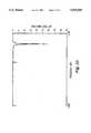
- FIG. 4is a plot of the amplitude characteristics of the directional coupler of FIGS. 1 and 2;
- FIG. 5is an idealized plot illustrating the characteristics of a double-tuned circuit
- FIGS. 6, 7 and 8illustrate field lines associated with a right circular cylindrical dielectric resonator
- FIG. 9illustrates a preferred directional coupler configuration
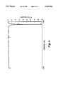
- FIGS. 10 and 11are amplitude-versus-frequency plots of notch filters according to the invention.
- a notch filter 10includes an electrically conductive gold-plated Titanium (or Kovar) ground plane 14, which supports a dielectric slab or substrate 12 of alumina (aluminum oxide).
- a 90°, 3 dB directional coupler or hybrid 16includes elongated, mutually parallel strip conductors 40a, 42a and 40b, 42b extending along the upper surface of substrate 12. Conductors 40a and 40b are directly connected by a crossover 41a, and conductors 42a and 42b are connected by a jumper wire 41b.
- Signals to be notch filteredare coupled into directional coupler 16 at an input port 17a by a connecting pin 34 of a coaxial connector (not otherwise visible), a jumper wire 38, and an elongated strip conductor 28.
- Notch-filtered signalis taken from directional coupler 16 at an output port 17b by a strip conductor 30, a jumper wire 36, and a connecting pin 32 of a coaxial connector 33.
- microstrip transmission linescapable of conveying signals in much the same manner as coaxial cables.
- microstrip transmission lineshave fields which extend outward from the strip conductor, and which can interact with surrounding structures, unlike conventional coaxial cables.
- microstrip transmission linesare configured to provide a 50-ohm characteristic impedance, but may be configured to other impedances to aid in impedance matching, tuning and the like.
- Three-dB quadrature directional couplerssuch as directional coupler 16, are also notoriously well known, being described, for example, in U.S. Pat. No. 4,602,227, issued Jul. 22, 1986 in the name of Clark et al.; and U.S. Pat. No. 5,146,177, issued Sep. 8, 1992 in the name of Katz et al.
- the salient aspect of a 3 dB, quadrature or 90° directional coupleris that the through transmission path has a length of approximately ⁇ /4 in the operating band, which provides a phase shift of about -90° between input port 17a and its direct port 17c.
- pin 34 of FIGS. 1 and 2is assumed to be the input port (although connector 33 could be the input instead) of the notch filter.
- the frequency range of directional coupler 16is selected to cover the range of signals to be passed. In an embodiment for passing signals in the range of 3.7 to 4.2 GHz, the directional coupler may have a range of operation encompassing that range.
- FIG. 4illustrates a plot 410 of the coupling between input port 17a and port 17d of directional coupler 16 with other ports terminated in the characteristic impedance, and plot 412 represents the corresponding coupling between ports 17a and 17c.
- the notch frequencydescribed below, is set to f HI .
- elongated strip conductor 18is connected to port 17c (the coupled 0° port) of directional coupler 16, and elongated strip conductor 20 is connected to port 17d (the direct 90° port).
- strip conductor 20connects with a further strip conductor 24 at a bend 210, and includes an impedance-matching notch or narrowing 212 adjacent bend 210 to introduce an inductive component to compensate for excess capacitance at bend 210.
- Strip conductor 24connects at bend 210 to strip conductor 20, and ends at an open-circuit 26.
- the end of strip conductor 18is connected at a bend 214 to another elongated strip conductor 22 and includes a narrowing or notch 216 adjacent bend 212.
- Strip conductor 22terminates in an open circuit 226.
- a dielectric resonator puck 40is mounted above the upper surface of dielectric sheet 12 by a spacer 58.
- Dielectric resonator 40is in the form of a right circular cylinder defining an axis 42.
- Axis 42is perpendicular to the surfaces of dielectric sheet 12 and ground plane 14.
- Spacer 58is also in the form of a right circular cylinder coaxial with axis 42.
- dielectric resonator puck 40is 0.233 inches high and has a diameter of 0.515 inches, and has a central bore 39 with a diameter of 0.083 inches. It is made from a ceramic Titanium Oxide dielectric material, type D8515, made by Trans Tech, Inc., the address of which is 5520 Adamstown Road, Adamstown, Md. 21710. This material has a nominal temperature characteristic of 0 parts per million/°C., with dopants selected by Trans Tech, Inc. for a precision of ⁇ 2 PPM/°C. over a wide temperature range.
- Spacer 58is type SPT-236-A-050, also supplied by Trans Tech, Inc., 0.236 inches in diameter and 0.050 inches high.
- the spaceraccording to the specification sheet, is a hollow Cordierite composition of Mg, Al and Silicate, with a coefficient of thermal expansion of 2.4 PPM/°C. over a wide temperature range. As described below, this is selected to aid in temperature compensating the notch filter for the effects of its housing, also described below.
- Spacer 58is adhesively affixed to puck 40 and to substrate 12 by a low-loss adhesive, such as a single-component epoxy adhesive type 84-3 made by Ablestik Laboratories, whose address is 833 W. 182 nd Street, Gardena, Calif. 90248.
- a plane illustrated as a dash line 44contains axis 42 of dielectric resonator 40. Plane 44 is orthogonal to the upper and lower surfaces of dielectric sheet 12.
- strip conductor 22defines an axis of elongation 222 lying parallel to the surface of dielectric sheet 12
- strip conductor 24defines an axis of elongation 224 parallel to axis 222.
- a point 232 on axis 222 of strip conductor 22, which lies one quarter wavelength ( ⁇ /4) from open-circuited end 226, also lies in plane 44, and corresponding point 234 on axis 224 of strip conductor 24is ⁇ /4 from open-circuit 26, and also lies in plane 44.
- This arrangementhas the advantage of placing a region of high electrical current on the transmission lines including strip conductors 22 and 24 at locations nearest the body of resonator 40.
- the high currentoccur at points 232 and 234, which are diametrically opposed to each other relative to axis 42, or which lie on radials (not illustrated) from axis 42 which are 180° apart.
- the axes of elongation 222 and 224 of strip conductors 22 and 24, respectivelyare parallel to tangents to the resonator body or puck.
- the high current on the transmission lineresults from the low impedance on the transmission line at a point ⁇ /4 from the high impedance of an open circuit.
- the characteristics of transmission linesare described in numerous sources, including the text Microwave Transmission Design Data, by Moreno, published by Dover in 1958, Lib. Congress Cat. No. 58-11278.
- the positioning according to the inventionmaximizes coupling into the puck of the dielectric resonator.
- the amount of couplingcan be increased by moving lines 22 and 24 toward resonator puck 40, with maximum coupling when they are directly under the edge of the puck.
- FIGS. 1 and 3illustrate another aspect of the invention.
- an adjustable capacitor 54is affixed to a lid 50 for moving a metal plunger 55 toward or away from dielectric resonator body 40 in order to adjust the frequency of a first mode of operation of resonator 40.
- plunger 55 of capacitor 54is centered on axis 42 of dielectric resonator puck 40, a tuning range of about five percent of the resonant frequency is available for a motion from 0.200 inches above the puck to 0.020 inches above the puck.
- the notchis narrow, and temperature drift attributable to capacitive effects of the housing may cause the notch to drift away from the signal whose amplitude is to be reduced or nulled, which in the downlink example may result in increasing distortion in the desired signals.
- the drift of the nullmay be due to the thermal expansion and/or contraction of the walls of the housing, which directly affects the capacitance between the housing walls and the puck, and the drift may also be due in part to the effect of thermal expansion and contraction of the housing walls on the position of capacitor 54 and its plunger 55.
- Making side walls 48 from aluminumwas found to aid in stabilizing the temperature response with the above-described Cordierite spacer.
- plunger 54is offset from axis 42, so that, as the plunger approaches body 40 of the resonator, the frequency of the fundamental TE 01 ⁇ mode rises, and the frequency of a second, high-order HE 11 ⁇ mode decreases, where the subscript ⁇ indicates a circular mode.
- a notch response similar to a double-tuned responseoccurs, which tends to have steeper shoulders and/or a deeper notch than a single-tuned response, and which thereby provides more rejection at the undesired frequency, with equal effect on adjacent frequencies which are passed.
- the double-tuned response 7has loss similar to that of a single-tuned response, but with improved notch depth.
- the dimensions of puck 40are initially selected to provide the coincidence at too low a frequency (a frequency below the desired frequency), and the upper surface of the puck is then shaved to bring the resonant frequency of the two modes to the desired value, which is 4.45 GHz in the example.
- FIG. 6is a frontal view of the structure of FIGS. 1, 2 and 3, illustrating the magnetic fields associated with resonance of puck 40 in the presence of plunger 55
- FIG. 7is a side view of the structure of FIG. 6.
- the magnetic fieldsare represented by dash lines.
- the magnetic fieldsform a toroidal magnetic structure, which is visible in the views of FIGS. 6 and 7 as "whorls" or circular structures.
- Plunger 55is symmetrical relative to the magnetic field whorls at right and left as seen in FIG. 6, but is offset toward the rear, as illustrated in FIG. 7. The presence of plunger 55 offset toward the rear of the magnetic field structure as in FIG.
- FIG. 8is a plan view of the resonator, which represents the magnetic fields in the puck of FIGS. 6 and 7, showing the magnetic fields by X s .
- the magnetic field densityis greater adjacent points 232 and 234.
- Notch filter 10operates, in general, by coupling energy from the directional coupler to the dielectric resonator, receiving the reflected energy, and combining the reflected energy out-of-phase to create the notch.
- the through loss of the notch filter at frequencies away from the notchis determined, in part, by the losses in the two legs coupled to the resonator, and by the losses of the resonator itself.
- the microstrip transmission lines and the dielectric resonatorare characterized by low loss.
- the depth of the notchis determined, in part, by the phase accuracy with which the mutually out-of-phase signals can be combined.
- the simple coupler illustrated in FIGS. 1 and 2is effective for limited notch depths.
- FIG. 9outlines the pattern of a Lange-style coupler which provides improved performance.
- the ends of transmission line strip conductors 18, 20, 28 and 30are tapered to a narrow width where they join the strip conductors 740, 742 of coupler 916.
- Strip conductor 28connects directly to a coupler strip 740a at port 17a, and also connects directly to another coupler strip 740c.
- Strip conductor 30connects directly to a coupler strip 742b at port 17b.
- Coupler strip 742bis coaxial with coupler strip 740a, and connects to the right end of coupler strip 742c.
- Coupler strip 742clies between coupler strips 740a and 740c, and has its left end connected by a jumper 741c to strip conductor 18 at port 17d.
- Strip conductor 20connects directly to a coupler strip 740b and a coupler strip 740d.
- Coupler strip 740bis coaxial with coupler strip 742c, and coupler strip 740d is coaxial with coupler strip 742a.
- a coupler strip 742dlies between coupler strips 740b and 740d, is coupled directly to the right end of coupler strip 742a, and is coupled at its right end, by a jumper 741d, to strip conductor 30 at port 17b.
- a jumper 741acouples the right end of coupler strip 740a to the junction of coupler strips 740b and 742c, and a jumper 741b couples the left end of coupler strip 740d to the junction of coupler strips 740b and 740c.
- FIG. 10plots the frequency response of a breadboard notch filter according to the invention, in which the higher-order resonator mode is not superposed on the fundamental mode.
- the notch depth attributable to the fundamental modeis about 27 dB, and the through loss at markers 1 and 2 is about 0.37 dB.
- FIG. 11plots the frequency response of another notch filter, with plunger adjusted to bring the fundament and higher-order modes into congruence, but with the dielectric resonator puck unshaved, so the notch is at too low a frequency.
- the notchis about -45 dB, a significant improvement over the 27 dB achieved with the fundamental mode alone in FIG. 10.
- transmission lines 22 and 24may have strip conductors which are tapered to a greater width adjacent the open-circuit termination to reduce the effects of fringing capacitance, and a lesser width at points 232 and 234, to increase the impedance by transformation.
- a pair of narrowings such as 216 of strip conductor 18could be placed on each side of the bend, to turn the excess capacitance of the bend into a low-pass filter.
Landscapes
- Physics & Mathematics (AREA)
- Electromagnetism (AREA)
- Control Of Motors That Do Not Use Commutators (AREA)
Abstract
Description
Claims (9)
Priority Applications (1)
| Application Number | Priority Date | Filing Date | Title |
|---|---|---|---|
| US08/205,212US5525945A (en) | 1994-01-27 | 1994-01-27 | Dielectric resonator notch filter with a quadrature directional coupler |
Applications Claiming Priority (1)
| Application Number | Priority Date | Filing Date | Title |
|---|---|---|---|
| US08/205,212US5525945A (en) | 1994-01-27 | 1994-01-27 | Dielectric resonator notch filter with a quadrature directional coupler |
Publications (1)
| Publication Number | Publication Date |
|---|---|
| US5525945Atrue US5525945A (en) | 1996-06-11 |
Family
ID=22761280
Family Applications (1)
| Application Number | Title | Priority Date | Filing Date |
|---|---|---|---|
| US08/205,212Expired - LifetimeUS5525945A (en) | 1994-01-27 | 1994-01-27 | Dielectric resonator notch filter with a quadrature directional coupler |
Country Status (1)
| Country | Link |
|---|---|
| US (1) | US5525945A (en) |
Cited By (32)
| Publication number | Priority date | Publication date | Assignee | Title |
|---|---|---|---|---|
| US5949309A (en)* | 1997-03-17 | 1999-09-07 | Communication Microwave Corporation | Dielectric resonator filter configured to filter radio frequency signals in a transmit system |
| US6107898A (en)* | 1998-04-30 | 2000-08-22 | The United State Of America As Represented By The Secretary Of The Navy | Microwave channelized bandpass filter having two channels |
| US6507251B2 (en)* | 2000-09-19 | 2003-01-14 | Murata Manufacturing Co., Ltd. | Dual-mode band-pass filter |
| US6603375B2 (en)* | 2001-07-13 | 2003-08-05 | Tyco Electronics Corp | High Q couplings of dielectric resonators to microstrip line |
| US20040051603A1 (en)* | 2002-09-17 | 2004-03-18 | Pance Kristi Dhimiter | Cross-coupled dielectric resonator circuit |
| US20040051602A1 (en)* | 2002-09-17 | 2004-03-18 | Pance Kristi Dhimiter | Dielectric resonators and circuits made therefrom |
| US20040257176A1 (en)* | 2003-05-07 | 2004-12-23 | Pance Kristi Dhimiter | Mounting mechanism for high performance dielectric resonator circuits |
| US20050200437A1 (en)* | 2004-03-12 | 2005-09-15 | M/A-Com, Inc. | Method and mechanism for tuning dielectric resonator circuits |
| US20050237135A1 (en)* | 2004-04-27 | 2005-10-27 | M/A-Com, Inc. | Slotted dielectric resonators and circuits with slotted dielectric resonators |
| US20060273869A1 (en)* | 2005-06-06 | 2006-12-07 | Jachowski Douglas R | Narrow-band absorptive bandstop filter with multiple signal paths |
| US20070090899A1 (en)* | 2005-10-24 | 2007-04-26 | M/A-Com, Inc. | Electronically tunable dielectric resonator circuits |
| US20070115080A1 (en)* | 2005-09-27 | 2007-05-24 | M/A-Com, Inc. | Dielectric resonators with axial gaps and circuits with such dielectric resonators |
| US20070159275A1 (en)* | 2006-01-12 | 2007-07-12 | M/A-Com, Inc. | Elliptical dielectric resonators and circuits with such dielectric resonators |
| US20070296529A1 (en)* | 2006-06-21 | 2007-12-27 | M/A-Com, Inc. | Dielectric Resonator Circuits |
| US20080117003A1 (en)* | 2006-11-16 | 2008-05-22 | Harris Corporation | Hairpin microstrip bandpass filter |
| US7388457B2 (en) | 2005-01-20 | 2008-06-17 | M/A-Com, Inc. | Dielectric resonator with variable diameter through hole and filter with such dielectric resonators |
| US20080272860A1 (en)* | 2007-05-01 | 2008-11-06 | M/A-Com, Inc. | Tunable Dielectric Resonator Circuit |
| US20080272861A1 (en)* | 2007-05-02 | 2008-11-06 | M/A-Com, Inc. | Cross coupling tuning apparatus for dielectric resonator circuit |
| US20090239752A1 (en)* | 2004-09-29 | 2009-09-24 | Fujitsu Limited | Superconducting device, fabrication method thereof, and filter adjusting method |
| US8305164B1 (en) | 2009-06-09 | 2012-11-06 | The United States Of America, As Represented By The Secretary Of The Navy | Frequency-agile frequency-selective variable attenuator |
| TWI424612B (en)* | 2010-03-05 | 2014-01-21 | Ralink Technology Corp | Broadband coupling filter |
| WO2016100713A1 (en)* | 2014-12-17 | 2016-06-23 | Parrott Ronald A | Ferrite resonators using magnetic-biasing and spin precession |
| US9755668B2 (en) | 2015-09-30 | 2017-09-05 | Abtum Inc. | Radio frequency complex reflection coefficient reader |
| US9762416B2 (en) | 2015-09-08 | 2017-09-12 | Abtum Inc. | Reflection coefficient reader |
| US9866201B2 (en) | 2015-09-08 | 2018-01-09 | Abtum Inc. | All-acoustic duplexers using directional couplers |
| US9912326B2 (en) | 2015-09-08 | 2018-03-06 | Abtum Inc. | Method for tuning feed-forward canceller |
| US10038458B2 (en) | 2015-10-06 | 2018-07-31 | Abtum Inc. | Reflection-based radio-frequency multiplexers |
| US10476530B2 (en) | 2015-10-12 | 2019-11-12 | Qorvo Us, Inc. | Hybrid-coupler-based radio frequency multiplexers |
| US10581650B2 (en) | 2015-09-08 | 2020-03-03 | Qorvo Us, Inc. | Enhancing isolation in radio frequency multiplexers |
| US10615949B2 (en) | 2014-02-14 | 2020-04-07 | University Of Southern California | Hybrid-based cancellation in presence of antenna mismatch |
| US10855246B2 (en) | 2016-09-21 | 2020-12-01 | Qorvo Us, Inc. | Enhancing isolation in hybrid-based radio frequency duplexers and multiplexers |
| WO2021179758A1 (en)* | 2020-03-10 | 2021-09-16 | 京信通信技术(广州)有限公司 | Filter and dielectric resonator thereof |
Citations (14)
| Publication number | Priority date | Publication date | Assignee | Title |
|---|---|---|---|---|
| US2749523A (en)* | 1951-12-01 | 1956-06-05 | Itt | Band pass filters |
| US3142028A (en)* | 1962-05-31 | 1964-07-21 | Hughes Aircraft Co | Waveguide stop-band filter utilizing hybrid circuit with lossy resonant cavities in branch arms |
| US3882434A (en)* | 1973-08-01 | 1975-05-06 | Microwave Dev Lab | Phase equalized filter |
| US3899759A (en)* | 1974-04-08 | 1975-08-12 | Microwave Ass | Electric wave resonators |
| US3919673A (en)* | 1974-06-05 | 1975-11-11 | Bell Telephone Labor Inc | Nonreciprocal absorption filter |
| US4218666A (en)* | 1979-04-27 | 1980-08-19 | Premier Microwave Corporation | Dual mode band rejection filter |
| JPS55138902A (en)* | 1979-04-17 | 1980-10-30 | Nippon Telegr & Teleph Corp <Ntt> | Signal separating coupling circuit |
| JPS5675704A (en)* | 1979-11-26 | 1981-06-23 | Fujitsu Ltd | Dielectric resonator |
| JPS58120301A (en)* | 1982-01-12 | 1983-07-18 | Sony Corp | Band pass filter |
| US4543543A (en)* | 1982-12-03 | 1985-09-24 | Raytheon Company | Magnetically tuned resonant circuit |
| US4945324A (en)* | 1986-11-28 | 1990-07-31 | Sony Corporation | Thin film ferromagnetic resonance tuned filter |
| US4983936A (en)* | 1986-07-02 | 1991-01-08 | Sony Corporation | Ferromagnetic resonance device |
| US4998080A (en)* | 1989-06-02 | 1991-03-05 | Polytechnic University | Microwave channelizer based on coupled YIG resonators |
| JPH0435505A (en)* | 1990-05-31 | 1992-02-06 | Sumitomo Electric Ind Ltd | band rejection filter |
- 1994
- 1994-01-27USUS08/205,212patent/US5525945A/ennot_activeExpired - Lifetime
Patent Citations (14)
| Publication number | Priority date | Publication date | Assignee | Title |
|---|---|---|---|---|
| US2749523A (en)* | 1951-12-01 | 1956-06-05 | Itt | Band pass filters |
| US3142028A (en)* | 1962-05-31 | 1964-07-21 | Hughes Aircraft Co | Waveguide stop-band filter utilizing hybrid circuit with lossy resonant cavities in branch arms |
| US3882434A (en)* | 1973-08-01 | 1975-05-06 | Microwave Dev Lab | Phase equalized filter |
| US3899759A (en)* | 1974-04-08 | 1975-08-12 | Microwave Ass | Electric wave resonators |
| US3919673A (en)* | 1974-06-05 | 1975-11-11 | Bell Telephone Labor Inc | Nonreciprocal absorption filter |
| JPS55138902A (en)* | 1979-04-17 | 1980-10-30 | Nippon Telegr & Teleph Corp <Ntt> | Signal separating coupling circuit |
| US4218666A (en)* | 1979-04-27 | 1980-08-19 | Premier Microwave Corporation | Dual mode band rejection filter |
| JPS5675704A (en)* | 1979-11-26 | 1981-06-23 | Fujitsu Ltd | Dielectric resonator |
| JPS58120301A (en)* | 1982-01-12 | 1983-07-18 | Sony Corp | Band pass filter |
| US4543543A (en)* | 1982-12-03 | 1985-09-24 | Raytheon Company | Magnetically tuned resonant circuit |
| US4983936A (en)* | 1986-07-02 | 1991-01-08 | Sony Corporation | Ferromagnetic resonance device |
| US4945324A (en)* | 1986-11-28 | 1990-07-31 | Sony Corporation | Thin film ferromagnetic resonance tuned filter |
| US4998080A (en)* | 1989-06-02 | 1991-03-05 | Polytechnic University | Microwave channelizer based on coupled YIG resonators |
| JPH0435505A (en)* | 1990-05-31 | 1992-02-06 | Sumitomo Electric Ind Ltd | band rejection filter |
Non-Patent Citations (2)
| Title |
|---|
| Instruction Sheet Jerrold Model 3880 Solid State High Output VHF Broadband Amplifier, #435-674-03, published by Jerrold Electronics Corporation Apr. 1973. |
| Instruction Sheet Jerrold Model 3880 Solid State High Output VHF Broadband Amplifier, 435 674 03, published by Jerrold Electronics Corporation Apr. 1973.* |
Cited By (53)
| Publication number | Priority date | Publication date | Assignee | Title |
|---|---|---|---|---|
| US5949309A (en)* | 1997-03-17 | 1999-09-07 | Communication Microwave Corporation | Dielectric resonator filter configured to filter radio frequency signals in a transmit system |
| US6107898A (en)* | 1998-04-30 | 2000-08-22 | The United State Of America As Represented By The Secretary Of The Navy | Microwave channelized bandpass filter having two channels |
| US6507251B2 (en)* | 2000-09-19 | 2003-01-14 | Murata Manufacturing Co., Ltd. | Dual-mode band-pass filter |
| US6603375B2 (en)* | 2001-07-13 | 2003-08-05 | Tyco Electronics Corp | High Q couplings of dielectric resonators to microstrip line |
| US7183881B2 (en) | 2002-09-17 | 2007-02-27 | M/A-Com, Inc. | Cross-coupled dielectric resonator circuit |
| US20040051603A1 (en)* | 2002-09-17 | 2004-03-18 | Pance Kristi Dhimiter | Cross-coupled dielectric resonator circuit |
| US20040051602A1 (en)* | 2002-09-17 | 2004-03-18 | Pance Kristi Dhimiter | Dielectric resonators and circuits made therefrom |
| US20050200435A1 (en)* | 2002-09-17 | 2005-09-15 | M/A-Com, Inc. | Cross-coupled dielectric resonator circuit |
| US7310031B2 (en) | 2002-09-17 | 2007-12-18 | M/A-Com, Inc. | Dielectric resonators and circuits made therefrom |
| US20040257176A1 (en)* | 2003-05-07 | 2004-12-23 | Pance Kristi Dhimiter | Mounting mechanism for high performance dielectric resonator circuits |
| US20050200437A1 (en)* | 2004-03-12 | 2005-09-15 | M/A-Com, Inc. | Method and mechanism for tuning dielectric resonator circuits |
| US20060197631A1 (en)* | 2004-03-12 | 2006-09-07 | M/A-Com, Inc. | Method and mechanism for tuning dielectric resonator circuits |
| US7352263B2 (en) | 2004-03-12 | 2008-04-01 | M/A-Com, Inc. | Method and mechanism for tuning dielectric resonator circuits |
| US20060238276A1 (en)* | 2004-04-27 | 2006-10-26 | Pance Kristi D | Slotted dielectric resonators and circuits with slotted dielectric resonators |
| US7088203B2 (en) | 2004-04-27 | 2006-08-08 | M/A-Com, Inc. | Slotted dielectric resonators and circuits with slotted dielectric resonators |
| US20050237135A1 (en)* | 2004-04-27 | 2005-10-27 | M/A-Com, Inc. | Slotted dielectric resonators and circuits with slotted dielectric resonators |
| US20090239752A1 (en)* | 2004-09-29 | 2009-09-24 | Fujitsu Limited | Superconducting device, fabrication method thereof, and filter adjusting method |
| US7904129B2 (en)* | 2004-09-29 | 2011-03-08 | Fujitsu Limited | Superconducting device with a disk shape resonator pattern that is adjustable in bandwidth |
| US7388457B2 (en) | 2005-01-20 | 2008-06-17 | M/A-Com, Inc. | Dielectric resonator with variable diameter through hole and filter with such dielectric resonators |
| US7323955B2 (en) | 2005-06-06 | 2008-01-29 | The United States Of America As Represented By The Secretary Of The Navy | Narrow-band absorptive bandstop filter with multiple signal paths |
| US20060273869A1 (en)* | 2005-06-06 | 2006-12-07 | Jachowski Douglas R | Narrow-band absorptive bandstop filter with multiple signal paths |
| US20070115080A1 (en)* | 2005-09-27 | 2007-05-24 | M/A-Com, Inc. | Dielectric resonators with axial gaps and circuits with such dielectric resonators |
| US7583164B2 (en) | 2005-09-27 | 2009-09-01 | Kristi Dhimiter Pance | Dielectric resonators with axial gaps and circuits with such dielectric resonators |
| US7352264B2 (en) | 2005-10-24 | 2008-04-01 | M/A-Com, Inc. | Electronically tunable dielectric resonator circuits |
| US20070090899A1 (en)* | 2005-10-24 | 2007-04-26 | M/A-Com, Inc. | Electronically tunable dielectric resonator circuits |
| US20070159275A1 (en)* | 2006-01-12 | 2007-07-12 | M/A-Com, Inc. | Elliptical dielectric resonators and circuits with such dielectric resonators |
| US7705694B2 (en) | 2006-01-12 | 2010-04-27 | Cobham Defense Electronic Systems Corporation | Rotatable elliptical dielectric resonators and circuits with such dielectric resonators |
| US20070296529A1 (en)* | 2006-06-21 | 2007-12-27 | M/A-Com, Inc. | Dielectric Resonator Circuits |
| US7719391B2 (en) | 2006-06-21 | 2010-05-18 | Cobham Defense Electronic Systems Corporation | Dielectric resonator circuits |
| US20100156567A1 (en)* | 2006-11-16 | 2010-06-24 | Harris Stratex Networks, Inc. | Hairpin Microstrip Bandpass Filter |
| US20080117003A1 (en)* | 2006-11-16 | 2008-05-22 | Harris Corporation | Hairpin microstrip bandpass filter |
| US7965158B2 (en) | 2006-11-16 | 2011-06-21 | Harris Stratex Networks, Inc. | Hairpin microstrip bandpass filter |
| WO2008064017A3 (en)* | 2006-11-16 | 2008-11-20 | Harris Stratex Networks Operat | Hairpin microstrip bandpass filter |
| US7688162B2 (en) | 2006-11-16 | 2010-03-30 | Harris Stratex Networks, Inc. | Hairpin microstrip bandpass filter |
| US20080272860A1 (en)* | 2007-05-01 | 2008-11-06 | M/A-Com, Inc. | Tunable Dielectric Resonator Circuit |
| US7456712B1 (en) | 2007-05-02 | 2008-11-25 | Cobham Defense Electronics Corporation | Cross coupling tuning apparatus for dielectric resonator circuit |
| US20080272861A1 (en)* | 2007-05-02 | 2008-11-06 | M/A-Com, Inc. | Cross coupling tuning apparatus for dielectric resonator circuit |
| US8305164B1 (en) | 2009-06-09 | 2012-11-06 | The United States Of America, As Represented By The Secretary Of The Navy | Frequency-agile frequency-selective variable attenuator |
| TWI424612B (en)* | 2010-03-05 | 2014-01-21 | Ralink Technology Corp | Broadband coupling filter |
| US10615949B2 (en) | 2014-02-14 | 2020-04-07 | University Of Southern California | Hybrid-based cancellation in presence of antenna mismatch |
| WO2016100713A1 (en)* | 2014-12-17 | 2016-06-23 | Parrott Ronald A | Ferrite resonators using magnetic-biasing and spin precession |
| US9912326B2 (en) | 2015-09-08 | 2018-03-06 | Abtum Inc. | Method for tuning feed-forward canceller |
| US9866201B2 (en) | 2015-09-08 | 2018-01-09 | Abtum Inc. | All-acoustic duplexers using directional couplers |
| US9762416B2 (en) | 2015-09-08 | 2017-09-12 | Abtum Inc. | Reflection coefficient reader |
| US10581650B2 (en) | 2015-09-08 | 2020-03-03 | Qorvo Us, Inc. | Enhancing isolation in radio frequency multiplexers |
| US9755668B2 (en) | 2015-09-30 | 2017-09-05 | Abtum Inc. | Radio frequency complex reflection coefficient reader |
| US10038458B2 (en) | 2015-10-06 | 2018-07-31 | Abtum Inc. | Reflection-based radio-frequency multiplexers |
| US10476530B2 (en) | 2015-10-12 | 2019-11-12 | Qorvo Us, Inc. | Hybrid-coupler-based radio frequency multiplexers |
| US10560129B2 (en) | 2015-10-12 | 2020-02-11 | Qorvo Us, Inc. | Hybrid-coupler-based radio frequency multiplexers |
| US10673471B2 (en) | 2015-10-12 | 2020-06-02 | Qorvo Us, Inc. | Hybrid-coupler-based radio frequency multiplexers |
| US10673472B2 (en) | 2015-10-12 | 2020-06-02 | Qorvo Us, Inc. | Hybrid-coupler-based radio frequency multiplexers |
| US10855246B2 (en) | 2016-09-21 | 2020-12-01 | Qorvo Us, Inc. | Enhancing isolation in hybrid-based radio frequency duplexers and multiplexers |
| WO2021179758A1 (en)* | 2020-03-10 | 2021-09-16 | 京信通信技术(广州)有限公司 | Filter and dielectric resonator thereof |
Similar Documents
| Publication | Publication Date | Title |
|---|---|---|
| US5525945A (en) | Dielectric resonator notch filter with a quadrature directional coupler | |
| US6362706B1 (en) | Cavity resonator for reducing phase noise of voltage controlled oscillator | |
| EP0586760B1 (en) | Single toroid hybrid mode RF phase shifter | |
| US7375604B2 (en) | Compact bandpass filter for double conversion tuner | |
| EP0885469B1 (en) | A high frequency balun provided in a multilayer substrate | |
| US4211987A (en) | Cavity excitation utilizing microstrip, strip, or slot line | |
| US8284001B2 (en) | Differential filtering device with coplanar coupled resonators and filtering antenna furnished with such a device | |
| CN111883914B (en) | Dielectric resonator broadband antenna with filter characteristic based on SIW feeding | |
| JP2646594B2 (en) | Tuned oscillator | |
| EP0764996B1 (en) | Dielectric resonator capable of varying resonant frequency | |
| US5987315A (en) | Diode circuit in dielectric waveguide device, and detector and mixer using the diode circuit | |
| US4525690A (en) | N-port coupler | |
| US5406234A (en) | Tunable microwave filter apparatus having a notch resonator | |
| US4647869A (en) | Microwave solid-state amplifier | |
| WO2025139847A1 (en) | Circularly polarized array antenna and wireless communication device | |
| US4313097A (en) | Image frequency reflection mode filter for use in a high-frequency receiver | |
| US7610072B2 (en) | Superconductive stripline filter utilizing one or more inter-resonator coupling members | |
| CN115377680B (en) | Filtering medium resonator antenna based on forked branch and metal column composite structure | |
| US5170138A (en) | Single toroid hybrid mode RF phase shifter | |
| JPH08162812A (en) | High frequency coupler | |
| US6069543A (en) | Dielectric resonator capable of varying resonant frequency | |
| CA2260453C (en) | High-frequency module | |
| US6242992B1 (en) | Interdigital slow-wave coplanar transmission line resonator and coupler | |
| JPH0846413A (en) | Resonator and high frequency circuit element using the resonator | |
| JP4189971B2 (en) | Variable frequency type high frequency filter |
Legal Events
| Date | Code | Title | Description |
|---|---|---|---|
| AS | Assignment | Owner name:MARTIN MARIETTA CORPORATION, NEW JERSEY Free format text:ASSIGNMENT OF ASSIGNORS INTEREST;ASSIGNORS:CHIAPPETTA, MARK CHRISTOPHER;DAUKAS, JOHN SHODEN;REEL/FRAME:006907/0346 Effective date:19940121 | |
| FEPP | Fee payment procedure | Free format text:PAYOR NUMBER ASSIGNED (ORIGINAL EVENT CODE: ASPN); ENTITY STATUS OF PATENT OWNER: LARGE ENTITY | |
| STCF | Information on status: patent grant | Free format text:PATENTED CASE | |
| FEPP | Fee payment procedure | Free format text:PAYOR NUMBER ASSIGNED (ORIGINAL EVENT CODE: ASPN); ENTITY STATUS OF PATENT OWNER: LARGE ENTITY Free format text:PAYER NUMBER DE-ASSIGNED (ORIGINAL EVENT CODE: RMPN); ENTITY STATUS OF PATENT OWNER: LARGE ENTITY | |
| FPAY | Fee payment | Year of fee payment:4 | |
| FPAY | Fee payment | Year of fee payment:8 | |
| AS | Assignment | Owner name:LOCKHEED MARTIN CORPORATION, MARYLAND Free format text:MERGER;ASSIGNOR:MARTIN MARIETTA CORPORATION;REEL/FRAME:015386/0400 Effective date:19960128 | |
| FPAY | Fee payment | Year of fee payment:12 | |
| REMI | Maintenance fee reminder mailed |