US5525884A - Automatically guided vehicle - Google Patents
Automatically guided vehicleDownload PDFInfo
- Publication number
- US5525884A US5525884AUS08/386,763US38676395AUS5525884AUS 5525884 AUS5525884 AUS 5525884AUS 38676395 AUS38676395 AUS 38676395AUS 5525884 AUS5525884 AUS 5525884A
- Authority
- US
- United States
- Prior art keywords
- chassis
- wheel
- trolley
- drive unit
- steering
- Prior art date
- Legal status (The legal status is an assumption and is not a legal conclusion. Google has not performed a legal analysis and makes no representation as to the accuracy of the status listed.)
- Expired - Lifetime
Links
Images


Classifications
- G—PHYSICS
- G05—CONTROLLING; REGULATING
- G05D—SYSTEMS FOR CONTROLLING OR REGULATING NON-ELECTRIC VARIABLES
- G05D1/00—Control of position, course, altitude or attitude of land, water, air or space vehicles, e.g. using automatic pilots
- G05D1/02—Control of position or course in two dimensions
- G05D1/021—Control of position or course in two dimensions specially adapted to land vehicles
- G05D1/0259—Control of position or course in two dimensions specially adapted to land vehicles using magnetic or electromagnetic means
- G05D1/0263—Control of position or course in two dimensions specially adapted to land vehicles using magnetic or electromagnetic means using magnetic strips
- G—PHYSICS
- G05—CONTROLLING; REGULATING
- G05D—SYSTEMS FOR CONTROLLING OR REGULATING NON-ELECTRIC VARIABLES
- G05D1/00—Control of position, course, altitude or attitude of land, water, air or space vehicles, e.g. using automatic pilots
- G05D1/02—Control of position or course in two dimensions
- G05D1/021—Control of position or course in two dimensions specially adapted to land vehicles
- G05D1/0259—Control of position or course in two dimensions specially adapted to land vehicles using magnetic or electromagnetic means
- G05D1/0261—Control of position or course in two dimensions specially adapted to land vehicles using magnetic or electromagnetic means using magnetic plots
Definitions
- This inventionrelates to an unmanned, magnetically guided vehicle which carries various loads in a fully automated fashion, in a factory or a warehouse, along a guide path of a closed-looped magnetic tape.
- a guide system for AGVswherein a sensor-active area which is recognized by a sensor for steering control for each of the AGVs is provided, and each AGV contains a guide device which controls steering by keeping the boundary between said sensor-active area and the non-active area as close as possible to a predetermined position using the information from the sensor is disclosed. Further, in the Japan's Patent Publications No. S62-199811 and No. S63-126907 bands for magnetic guidance are disclosed.
- a vehicle which is constructed as a proper AGVfor example, develops a lot of resistance (especially magnetic resistance of the motor) when it is pushed to a place off the magnetic guide path in order to change paths or to moved the AGV to a charging station in order to charge the battery, making it very difficult to push it by hand.
- the primary object of the inventionis, therefore, to provide a magnetically guided vehicle system with excellent versatility and variability using guide paths consisting of magnetic tape laid along the path lines and a magnetic-guided steering drive unit which has a magnetic sensor to detect magnetism from the tape.
- the vehicle systemalso has a drive wheel, a driving means to drive the drive wheel and a steering means for the wheels, each provided under an attachment plate, a trolley to which the attachment plate for the steering drive unit is attached on the lower surface of the chassis, and a carriage shelf assembly provided with one or more layers of automatic conveyers mounted on the chassis of trolley.
- the magnetically guided vehiclewould be able to be used either as a magnetically guided vehicle system when the trolley, steering drive unit and carriage shelves are combined, or as an normal trolley when disassembled.
- Another object of the inventionis to provide a magnetically guided vehicle which has the drive wheel of the steering drive unit touching the floor with a pressure sufficient for running and can be changed so that the drive wheel is suspended above the floor, making it very convenient for hand pushing when the vehicle must be moved to a place without magnetic guide tape in order to change paths or to a charge station, having no guide path, for charging batteries.
- the magnetically guided vehicle systemcomprises guide paths consisting of magnetic tape laid along the path lines and a magnetic-guided steering drive unit which has a magnetic sensor to detect magnetism from the tape.
- the MGVhas a drive wheel, a steering drive unit with a driving means to drive the drive wheel and a steering means, both provided under an attachment plate and controlled automatically through a control means that processes signals detected by the magnetic sensor.
- the MGVfurther has a trolley, which has a wheel at each of the four corners of the lower surface of the chassis, the front wheels having a universal caster, and is provided with an attachment plate for the steering drive unit fixed on the lower surface of the chassis.
- the MGValso has a carriage shelf assembly which has one or more horizontal automatic roller conveyers as shelves mounted on said chassis of the trolley.
- the attachment plateis removably fixed to the lower surface of the chassis and the carriage shelves are also removably mounted on the chassis. The conveyers are operated automatically according to a transmitted signal when a load handling position on the path is detected.
- the drive wheel of the steering drive unitis attached to a mechanism which moves vertically by a lever which changes the wheel from a position in which the wheel touches the floor, pushing up the attachment plate fixed on the lower surface of the chassis with the pressure necessary for running, to a position in which the wheel is suspended off the floor.
- a changeover handle to move the drive wheel verticallyis provided at the rear of the chassis.
- the frame for the chassis and the carriage shelf assemblyare constructed by connecting resin-coated steel pipes with connecters.
- the attachment plate of the steering drive unitis detachably mounted by fastening hold plates which receive the resin-coated steel pipes to attachment seats of the attachment plate with bolts.
- the carriage shelf assemblyis mounted detachably by two-piece connecters fastened with nuts and bolts that clamp symmetrically the resin-coated steel pipes constituting the frame of the carriage shelf assembly and the steel pipes constituting the frame of the chassis of the trolley.
- the automatic conveyers of the carriage shelf assemblyconsist of rollers made of resin-coated steel pipes cut to suitable lengths and supported rotatably by bearing means at both ends of each pipe. There may be a number of rollers arranged parallel with each other at a constant pitch and are driven in a common direction at a common speed. Sensors are provided at both the entrance and exit sides of each of the roller conveyers which sense on-coming and off-going loads. Stopper means that can be either turned up or turned down are provided at both the entrance and exit sides for stopping loads.
- the magnetically guided vehicleis started through manipulation of a start button by an operator.
- the software of the control deviceis programmed in such a way that, after starting, the system will run repeatedly as an unmanned operation.
- the magnetic sensordetects magnetism (magnetic force line) that is emitted from the magnetic tape laid along the path on the floor.
- the control deviceprocesses the detected magnetism, drives the steering motor of the steering device and thereby steers the drive wheel, which enables the vehicle to run along the path without human operation.
- Another magnetic sensor(N/S magnetic sensor) detects S and N poles of small pieces of magnetic tape laid independently at load handling positions (loading or unloading positions) and receives signals for decelerating or stopping.
- the signalsare also processed by the same control device for control of the driving device, which decelerates or stops the drive wheel.
- the stop signalis also used as a start signal for the roller conveyers of the carriage shelf assembly and controls the drive motors automatically for starting rotation in the direction for loading or for unloading.
- the drive motors for the rollersare stopped by a signal transmitted from either of the sensors when a load enters or leaves the conveyer.
- the stopper meansprevents overrun or a dropping of the load from the conveyer. In this way, the vehicle is operated without human manipulation, repeating automatically a cycle of runs along the guide path by halting, loading and unloading.
- the magnetically guided vehicleBy attaching the attachment plate on the lower surface of the chassis of the trolley and mounting the carriage shelf assembly on the upper surface of the chassis of the trolley, the magnetically guided vehicle (AGV) is completed.
- Any type of trolleynew or conventional, can be used as long as the attachment of the attachment plate is compatible with it. If the magnetically guided vehicle is disassembled in reverse, the trolley can be used for its original purposes.
- the magnetic resistance of the drive device(especially the drive motor) is completely resolved and the vehicle can then be relatively easily moved by hand off the guide path when the path is changed through renewal of the guide tape or when the vehicle is being transferred to a charging station that has no guide path.
- the vehicleSince the vehicle is constructed by connecting the resin-coated steel pipes of the frames of the chassis of the trolley and of the carriage shelf assembly, it is more resilient and there is a lower probability of a person being hurt or an object colliding with it being damaged as compared to vehicles made of shape steel or uncoated metal pipes.
- Such pipesare excellent in terms of corrosion resistance (resistance to acid, alkali, water) and, therefore, convenient for use in places where corrosion is a matter of concern.
- the attachment plate for the vehicle according to the present inventionis easily detachably attached to the chassis of the trolley with the hold plates and bolts, as is the carriage shelf assembly with the two-piece connecters, nuts and bolts.
- a magnetically guided vehiclecan be constructed by combining a trolley, a steering drive unit and a carriage shelf assembly and the trolley can also be reduced to its original form and be used for its original purposes by disassembling the vehicle, which gives the vehicle excellent versatility and variability.
- any type of trolley, new or conventionalcan be used as long as the specification is compatible with the construction of the vehicle according to the present invention.
- the vehiclecan be very conveniently and easily moved by hand off the guide path in order to change paths or to transfer it to a charging station for battery charging.
- FIG. 1is a diagonal view of an example of the use of the magnetically guided vehicle according to the present invention.
- FIG. 2is a plan view showing the positional relation of magnetic tape and the sensor
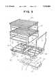
- FIG. 3is a diagonal view showing the components of the magnetically guided vehicle in a disassembled condition
- FIG. 4is a diagonal view showing schematically the general construction of the magnetically guided vehicle according to the present invention.
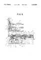
- FIG. 5is a side elevational view showing the main part of the magnetically guided vehicle according to the present invention.
- FIG. 6is a plan view of the steering drive unit
- FIG. 7is a sectional view showing in detail the drive wheel portion of the steering drive unit
- FIG. 8is a back view showing the movement of the changeover handle which moves the drive wheel of the steering drive unit vertically;
- FIG. 9is a diagonal view showing the construction of the roller conveyer of the carriage shelf assembly for the magnetically guided vehicle
- FIG. 10is a sectional view showing the bearing means portion of the roller conveyer for the carriage shelf assembly.
- FIG. 11is a diagonal view of the stopper means to prevent a load from falling off the roller conveyer.
- FIG. 1shows an example of the use of the magnetically guided vehicle according to the present invention (abbreviated hereinafter as AGV ).
- the AGVruns in the direction of the arrow A continuously without human operation on a path formed as a closed loop with magnetic tape 15 laid along the path line, the control process being such that a magnetic sensor 5 detects the intensity and direction of the magnetic force lines from the magnetic tape 15 and the drive wheel 3 is driven and steered by a steering motor which is controlled in such a manner as to keep the left side (or the right side) edge line at a predetermined position of the sensor 5.
- the load Wthen moves in the direction designated by the arrow, and, after other work, sorting, etc., enters a platform D of an elevator E. Meanwhile, the AGV advances along the guide path and, halting at the stop position B-2, receives said load W on the upper automatic roller conveyer 10b from the platform D which has been waiting at lifted position D'. The AGV then moves ahead further and stops at the junction with a flow rack G and transfers the load W to the upper flow rack G1. At an assembly conveyer line T, in front of said flow rack G, workers take out the contents from the load W for assembly work and the empty box W' is returned by way of the lower flow rack G2. The empty box W' is received on the lower roller conveyer 10a as a return load.
- the AGVagain stops at the end of the carry-in conveyer M, position B-1 and sends out the empty box W' to a transfer conveyer H'. Further, it also relays the load W that comes from the carry-in conveyer M to the transfer conveyer H'.
- the empty box W' put on said transfer conveyer H'is checked by a watch sensor (not shown) while proceeding on a conveyer K, and, being recognized as empty, it is directed to another transfer conveyer C that is perpendicular to the conveyer K by a direction changer L. Then, the empty box W' is sent onto the lower automatic conveyer 10 a of the AGV that has advanced along the guide path and halted at the load handling position B-1.
- the AGVafter the watch sensor has confirmed the completion of the loading of the returned load, that is, the empty box W', starts moving automatically and stops at the next load handling position B-2. At this position, the AGV moves the empty box W' form the lower automatic conveyer 10a onto the conveyer of the platform D of the elevator E. The empty box on the platform D is then lifted by the elevator to the height of the entrance level D' of an inclined conveyer F and then, via said inclined conveyer F, is moved on the carry-out conveyer N in the direction designated by the arrow and returns to the original supply site. These processes and actions constitute a cycle which is repeated.
- FIGS. 3-5the actual construction of the AGV (the magnetically guided vehicle 1) is shown in FIGS. 3-5.
- This AGVis equipped with a magnetic sensor and a magnetic guide-type steering drive unit 24 which has a drive wheel 3 and a driving device for the wheel (such as driving motor 2).
- the AGVhas a steering device under an attachment plate 25, a trolley 26 with four wheels at each of its corners, the front wheels having universal casters, which can be attached the lower surface of the chassis by the attachment plate 25 of the steering drive unit 24.
- the AGValso has a carriage shelf assembly 21 which has one or more layers of horizontal automatic conveyers as shelves and is mounted on the chassis of the trolley 26.
- the AGV in FIG. 4is completed by detachably fixing the attachment plate 25 of the steering drive unit 24 to the lower surface of the chassis of the trolley 26 and by detachably mounting the carriage shelf assembly 21 onto the chassis of the trolley.
- FIGS. 5-7show the detailed construction of the magnetic guide type steering drive unit 24.
- the attachment plate 25,which is made of a steel plate both side edges of which are bent downward to form a shallow box, has dimensions of approximately 170 ⁇ 650 mm.
- a movable plate 50is fitted which is also made of a steel plate, both side edges of which are bent upward to form a shallow box.
- These platesare connected rotatably at the rear portion of the overlapped side walls with a horizontal support pin 51 while in the front portion a pair of vertical guide pins 29, each having a buffer spring 30, are provided to permit vertical movement around the support pin 51.
- a bearing block 33 for a bearing 38 which rotatably supports a steering shaft 32 standing vertically from a holder 31 of the drive wheel 3is fixed to the lower surface of the movable plate 50 with a number of screws 34.
- a pulley 35is mounted which is coupled with a driving pulley 36 of a steering motor 4 with a timing belt 37.
- the drive wheel 3is steered automatically by the steering motor 4.
- the shaft 39 of the drive wheel 3is supported at both ends rotatably by the side walls of the holder 31 by bearings 41.
- a pulley 42 mounted at one end of the shaft 39is coupled with a drive pulley 76 of a driving motor 2 provided at the rear of the holder 31 with a timing belt 77.
- a battery 7is provided at the rear of the trolley 26 (FIG. 4) as power source for the steering motor 4, the driving motor 2 and the motors for the automatic roller conveyers described below.
- a control device 53which primarily governs the automatic control of the steering drive unit 24 is provided on the lower surface of the steering drive unit 24 (FIG. 5).
- a changeover mechanismchanges the drive wheel 3 from a position in which the wheel 3 touches the floor pushing up the attachment plate 25 with a pressure sufficient for running to a position in which the wheel is suspended with a clearance from the floor as shown in FIGS. 5, 6 and 8.
- the fore ends of the movable plate 50are supported through a support axle 45 by the fore ends of a pair of levers 44 which are provided on either side of the attachment plate 25 and rotatably supported at the middle by a trunnion shaft 43.
- a tie rod 46which couples the rear ends of the levers 44 is provided in such a manner that, as shown in FIG. 8, a cam follower 49 of an arm 48 which is turned by a manually operated changeover handle 47 presses against the rod 46.
- the changeover handle 47 and the arm 48Form the same phase angle and, as shown in FIG. 8, as the handle is turned to the vertical position (I), the cam follower 49 is received stably in a recessed position 46a of the tie rod 46 and thereby presses down the tie rod 46 the lowest position.
- the movable plate 50is turned upward about the fulcrum pin 51 following the levers 44 which are turned about the trunnion shaft 43 and pulls up the drive wheel 3 together with the holder 31 into the suspended position.
- the drive wheel 3is held in suspension under the chassis of the trolley 26 and the AGV is in a position to run on the front wheels 58 and the rear wheels 59.
- the AGVwhen the AGV must be hand-pushed in order to change of paths or to charge the battery, by turning said changeover handle to the vertical position (I) of FIG. 8 and thereby pulling up the drive wheel off the floor, the AGV can be moved in a light-load condition without the resistance of the driving means (the driving motor 2). Returning the manual handle 47 to position II of FIG. 8, the AGV is back in a position to run with the drive wheel 3. In response to unevenness of the floor, the cam follower 49 may rise to position III of FIG. 8 as the drive wheel 3 is pushed down by the buffer spring 30.
- a magnetic tape sensor 5is attached through a holding means 52 to the fore part of the holder 31 of the drive wheel 3 in the steering drive unit 24.
- a S/N magnetic sensor 40is also attached to the holder 31 but the position of attachment is not shown.
- the signals detected by each of said magnetic sensorsare input to a control device 53 and processed there.
- the control device 53then controls said steering motor 4 and the driving motor 2 through the output (control signals), that is, the processed signals.
- the frame of the trolley 26 and the frame of the carriage shelf assembly 21are constructed from resin-coated steel pipes connected with couplers formed by injection from synthetic resin such as polyethylene or with metal joints.
- the resin-coated steel pipesare of an outer diameter of 28 to 42 mm and made by first applying adhesive to the outer surface of thin steel pipe of a thickness of 0.6 mm, and then coating the pipe with thin layer of about 1 mm of synthetic resin such as ABS or AAS.
- the attachment plate 25 of the steering drive unit 24is introduced and mounted detachably by fastening hold plates 55 that are placed on the resin-coated steel pipes 54 constituting the chassis in such a manner as to hold the pipes in the semi-circular receivers with bolts 56 that ace screwed into attachment seats 57, of the attachment plate 25 (see FIG. 3).
- the trolley 26has a pair of front wheels 58 and a pair of rear wheels 59 on the lower surface of the chassis, the trolley is run through the revolutions of the single drive wheel 3 of said steering drive unit 24 and is steered according in the direction of the drive wheel 3, the trolley serving only as a carrier bed.
- Numeral 14 in FIG. 3 and 4designates a handle for hand pushing.
- the carriage shelf assemblyfor which the frame is constructed from resin-coated steel pipes as described above, is mounted detachably by placing the lower resin-coated steel pipes 18 of the frame of the trolley 26 directly on the peripheral resin-coated steel pipes 19 constituting the chassis of the trolley 26, clamping them with two-piece type eyeglasses-shaped couplers 20, and fastening the middle part of said couplers firmly with screws 60 and nuts.
- This carriage shelf assembly 21is provided with two layers of automatic roller conveyers 10a and 10b which also serve as shelves. Both of them are of the same construction and have a number of rollers 10' arranged at a constant pitch parallel to the direction of the forward movement of the AGV.
- rollers 10'are supported rotatably at both ends thereof by bearing means 16 attached to the longitudinal members 11 of the resin-coated steel pipes constituting the carriage shelf assembly 21.
- the construction of one of the rollers 10' and the bearing means 11are shown in detail in FIG. 10.
- the roller 10'is made by cutting a resin-coated pipe to a suitable length and has at each end a bearing bush 62, which serves also as a pulley 61, made of a kind of plastic inserted into the hollow and fixed there by adhesion.
- the base end 64a of a support axle 64which, inserted into a needle bearing 63 at the center of said bearing bush 62, supports said roller 10', is inserted and fixed in a glove 65a of a coupler 65 for bearing which bites said resin-coated steel pipe 11 and is fixed firmly through adhesion.
- all the members constituting the rollers 10', the bearing means 16 thereof and the frame of the carriage shelf assemblyare made of a synthetic resin or resin-coated steel pipes and hence do not have the cold feel or heaviness of naked metal. Moreover they manifest excellent corrosion resistance to water, sea water, agricultural chemicals or other corrosive gases.
- Each pulley 61 for the rollers 10'is individually connected with a cross-spanned belt 69 to the pulley 68 of a drive shaft 9.
- the drive shaft 9, which has a castellated surface,is provided directly under the rollers 10' in a perpendicular direction and is supported rotatably by bearing panels 17 (FIG. 9) which are attached to the resin-coated steel pipes constituting the frame of the carriage shelf assembly.
- a driven pulley 70is mounted which is connected with a drive pulley 66 by a belt 67.
- Each roller 10' of the upper and lower automatic conveyers 10b, 10ais controlled for rotation start and stop, the direction of rotation and revolution rate by a roller-driving motor 8 which is automatically controlled by a control device 6 (FIG. 4) provided in the rear of the carriage shelf assembly 21.
- This control device 6shares a signal circuit with the control device 53 of the steering drive unit described above and is interlocked therewith. In some cases, these two control devices 6 and 53 may be combined into one device.
- Each of the roller-driving motors 8is provided on a pair of the resin-coated steel pipes 72 that are connected to the resin-coated steel pipes 73 constituting the frame of the carriage shelf assembly 21 with two-piece screw-clamp type metal joints 71 (FIG. 9).
- a one-sided drive system with a pulley 61can be provided on only one side of each of the rollers 10', or a two-sided drive system with two pulleys, one on either side, can be provided. These can also be accompanied by a pair of parallel drive shafts 9 which are driven by a common driving motor, or some other two-sided drive system wherein each driving shaft 9 is driven individually by a drive motor 8, as appropriate.
- a set of photoelectric switcheseach having a light emitter 12 which emits watch light, as shown in FIG. 4, in a direction parallel to the rollers 10' with a receiver 12' which receives and executes photoelectric conversion of the emitted light, is mounted at each of the front and rear sides of the conveyers using the resin-coated steel pipes 11 constituting the frame of the carriage shelf assembly 21.
- the interception of the light by the loadfirst at the entrance and then, as the load reaches the end of the conveyer, at the rear, are detected as signals and input into control device 6.
- the control device 6processes the signals and stops the roller-driving motors 8.
- the two sensorsalso sense the load as it leaves the conveyer and the detected signals drive the roller-driving motors 8 through the control device 6.
- stoppers 22which can be turned up and down are attached via rotary solenoids 13 to prevent overrun and the dropping of a load, as shown in FIGS. 4 and 11.
- a metal piece 23is attached and fixed with a screw 75 and the rotary solenoid 13 is mounted on the metal piece 23.
- the one on the rear sideis basically always kept in the upright position and serves as a stopper to prevent the falling of a load due to an overrun.
- the rotary solenoid 13 on the entrance sideis given a signal to turn the stopper 22 about 90 degrees downward as a start signal is given to the roller-driving motors 8 from the control device 6 to take on a load.
- the stopperis controlled to stand upright to prevent the falling of the load from the front edge. Roughly the same control process takes place when a load is taken off of the conveyer.
- the above off casein which a load comes on from the entrance side and also goes off from the entrance side, is described above. This, however, is not always the case. It is also feasible for a load to come on from the entrance side and go off the exit side.
- the numeral 79 in the figuresdesignates guide pipes which are provided on both sides of the automatic conveyers 10b and 10a parallel to the direction of movement of the load and are supported by joints 80. These guide pipes 79 guide the load for entrance and exit and prevent a sideways fall of the load.
Landscapes
- Physics & Mathematics (AREA)
- Engineering & Computer Science (AREA)
- Electromagnetism (AREA)
- Aviation & Aerospace Engineering (AREA)
- Radar, Positioning & Navigation (AREA)
- Remote Sensing (AREA)
- General Physics & Mathematics (AREA)
- Automation & Control Theory (AREA)
- Warehouses Or Storage Devices (AREA)
Abstract
Description
Claims (4)
Priority Applications (1)
| Application Number | Priority Date | Filing Date | Title |
|---|---|---|---|
| US08/386,763US5525884A (en) | 1995-02-10 | 1995-02-10 | Automatically guided vehicle |
Applications Claiming Priority (1)
| Application Number | Priority Date | Filing Date | Title |
|---|---|---|---|
| US08/386,763US5525884A (en) | 1995-02-10 | 1995-02-10 | Automatically guided vehicle |
Publications (1)
| Publication Number | Publication Date |
|---|---|
| US5525884Atrue US5525884A (en) | 1996-06-11 |
Family
ID=23526954
Family Applications (1)
| Application Number | Title | Priority Date | Filing Date |
|---|---|---|---|
| US08/386,763Expired - LifetimeUS5525884A (en) | 1995-02-10 | 1995-02-10 | Automatically guided vehicle |
Country Status (1)
| Country | Link |
|---|---|
| US (1) | US5525884A (en) |
Cited By (84)
| Publication number | Priority date | Publication date | Assignee | Title |
|---|---|---|---|---|
| US5672947A (en)* | 1995-09-15 | 1997-09-30 | Yazaki Industrial Chemical Co., Ltd. | Automatic guide method for vehicles |
| FR2764077A1 (en)* | 1997-06-03 | 1998-12-04 | Ind Et Sport Sa | DEVICE FOR MONITORING AND MANAGING A TROLLEY |
| EP1099589A1 (en)* | 1999-11-09 | 2001-05-16 | Gehwolf, Friedrich | A self-propelled truck and a system comprising such a self-propelled truck |
| US6256560B1 (en)* | 1999-02-25 | 2001-07-03 | Samsung Electronics Co., Ltd. | Method for correcting position of automated-guided vehicle and apparatus therefor |
| US6390314B1 (en) | 2000-12-04 | 2002-05-21 | Advanced Micro Devices, Inc. | Automatic trolley clamp lock |
| WO2002072410A1 (en)* | 2001-03-12 | 2002-09-19 | Jervis B. Webb Company | Floating drive for vehicle |
| US6469466B1 (en)* | 1999-11-24 | 2002-10-22 | Denso Corporation | Automatic guided vehicle |
| US20020159869A1 (en)* | 2001-04-27 | 2002-10-31 | Yugo Fukuhara | Air cargo transport system |
| US6481521B2 (en)* | 2000-12-15 | 2002-11-19 | Yazaki Industrial Chemical Co., Ltd. | Under-cart type guided tractor |
| US6493614B1 (en)* | 2001-12-24 | 2002-12-10 | Samsung Electronics Co., Ltd. | Automatic guided system and control method thereof |
| US20030230450A1 (en)* | 2002-04-18 | 2003-12-18 | Robert Imberi | Self propelled scaffolding |
| US20040016579A1 (en)* | 2001-03-12 | 2004-01-29 | Coveyou Jon L. | Floating drive for vehicle |
| US20040187395A1 (en)* | 2002-11-12 | 2004-09-30 | Kongo Kabushiki Kaisha | Control method for moving racks |
| US20050113989A1 (en)* | 2001-08-24 | 2005-05-26 | Young David W. | Apparatus for cleaning lines on a playing surface and associated methods, enhancements |
| US20050244259A1 (en)* | 2004-05-03 | 2005-11-03 | Chilson Gerald E | Automatic transport loading system and method |
| US6971464B2 (en) | 2001-12-12 | 2005-12-06 | Jervis B. Webb Company | Driverless vehicle guidance system and method |
| US20060064212A1 (en)* | 2004-09-22 | 2006-03-23 | Cycle Time Corporation | Reactive automated guided vehicle vision guidance system |
| US20060276958A1 (en)* | 2005-06-02 | 2006-12-07 | Jervis B. Webb Company | Inertial navigational guidance system for a driverless vehicle utilizing laser obstacle sensors |
| US20070260371A1 (en)* | 2001-08-24 | 2007-11-08 | Young David W | Methods for cleaning lines on a game playing surface |
| US20080199298A1 (en)* | 2004-05-03 | 2008-08-21 | Jervis B. Webb Company | Automatic transport loading system and method |
| EP2168847A1 (en)* | 2008-09-26 | 2010-03-31 | Aichikikai Techno System Co., Ltd. | Automatic guided vehicle drive device |
| US20100104414A1 (en)* | 2008-10-23 | 2010-04-29 | Jervis B. Webb Company | Workpiece Transport Assembly And Method Of Using Same |
| US20100266381A1 (en)* | 2004-05-03 | 2010-10-21 | Jervis B. Webb Company | Automatic transport loading system and method |
| US20100316470A1 (en)* | 2009-04-10 | 2010-12-16 | Casepick Systems, Llc | Control system for storage and retrieval systems |
| US20110056760A1 (en)* | 2009-09-10 | 2011-03-10 | Jervis B. Webb Company | Load Handling Bumper For Material Handling Device |
| US20110224860A1 (en)* | 2001-08-24 | 2011-09-15 | David Wright Young | Apparatus for cleaning lines on a playing surface and associated methods, handle enhancements |
| US20110301800A1 (en)* | 2010-06-03 | 2011-12-08 | Hitachi Plant Technologies, Ltd. | Automatic guided vehicle and method for drive control of the same |
| US8075243B2 (en) | 2004-05-03 | 2011-12-13 | Jervis B. Webb Company | Automatic transport loading system and method |
| US20120068664A1 (en)* | 2009-06-10 | 2012-03-22 | Gottwald Port Technology Gmbh | System for replacing a battery of a ground transportation vehicle, particularly of an unmanned heavy-duty transportation vehicle for iso containers |
| US20120073889A1 (en)* | 2009-06-10 | 2012-03-29 | Gottwald Port Technology Gmbh | Heavy-duty ground transportation vehicle, in particular an unmanned heavy-duty transportation vehicle for iso containers |
| US8192137B2 (en) | 2004-05-03 | 2012-06-05 | Jervis B. Webb Company | Automatic transport loading system and method |
| CN102649395A (en)* | 2012-04-28 | 2012-08-29 | 湖北省机电研究设计院 | Automatic guided vehicle driving system |
| US8276692B1 (en)* | 2007-07-31 | 2012-10-02 | Prince Frederick Nwaeke | Electronic hand truck |
| US8696010B2 (en) | 2010-12-15 | 2014-04-15 | Symbotic, LLC | Suspension system for autonomous transports |
| US8751147B2 (en) | 2010-08-03 | 2014-06-10 | Fori Automation, Inc. | Sensor system and method for use with an automated guided vehicle (AGV) |
| US8965619B2 (en) | 2010-12-15 | 2015-02-24 | Symbotic, LLC | Bot having high speed stability |
| DE102013218377A1 (en)* | 2013-09-13 | 2015-03-19 | Siemens Aktiengesellschaft | Querbandsortertransportelement |
| US9033088B2 (en)* | 2013-02-14 | 2015-05-19 | Toyota Motor Engineering & Manufacturing North America, Inc. | Ergonomic work operation method and apparatus |
| CN104765361A (en)* | 2014-01-04 | 2015-07-08 | 江门市鸿强自动化设备有限公司 | Single-drive reciprocating turning-type AGV (Automated Guided Vehicle) |
| US9187244B2 (en) | 2010-12-15 | 2015-11-17 | Symbotic, LLC | BOT payload alignment and sensing |
| US9321591B2 (en) | 2009-04-10 | 2016-04-26 | Symbotic, LLC | Autonomous transports for storage and retrieval systems |
| WO2016082883A1 (en)* | 2014-11-27 | 2016-06-02 | Identytec Gmbh & Co. Kg | Material logistics system |
| US9499338B2 (en) | 2010-12-15 | 2016-11-22 | Symbotic, LLC | Automated bot transfer arm drive system |
| CN106327964A (en)* | 2016-08-24 | 2017-01-11 | 合肥凌翔信息科技有限公司 | Teaching experiment trolley tracking system |
| US9561905B2 (en) | 2010-12-15 | 2017-02-07 | Symbotic, LLC | Autonomous transport vehicle |
| WO2017054078A1 (en)* | 2015-10-02 | 2017-04-06 | Celebramotion Inc. | Method and system for people interaction and a guided cart therefor |
| US9637150B1 (en)* | 2013-06-27 | 2017-05-02 | Amazon Technologies, Inc. | Transport handle for low profile displacement |
| TWI615696B (en)* | 2016-12-06 | 2018-02-21 | 財團法人金屬工業研究發展中心 | Auto guided vehicle system and operating method thereof |
| US10035541B2 (en)* | 2011-03-25 | 2018-07-31 | Inf Robotics Incorporated | Robotic personal assistant |
| CN108398953A (en)* | 2018-04-26 | 2018-08-14 | 科大智能机器人技术有限公司 | The manned routing inspection trolley of electric power gallery |
| US20180370411A1 (en)* | 2015-12-15 | 2018-12-27 | Konecranes Global Corporation | Transport vehicle for containers |
| US10202061B2 (en)* | 2013-12-12 | 2019-02-12 | Grenzebach Maschinenbau Gmbh | Driver-free transport vehicle for the safe transportation of heavy loads |
| WO2019084330A1 (en)* | 2017-10-27 | 2019-05-02 | Berkshire Grey, Inc. | Systems and methods for processing objects including mobile matrix carrier systems |
| US20190235522A1 (en)* | 2018-01-31 | 2019-08-01 | Metal Industries Research & Development Centre | Auto guided vehicle system and operating method thereof |
| US10558223B2 (en) | 2017-10-26 | 2020-02-11 | Rovibec Inc. | Autonomous vehicle for pushing feed, methods and systems thereof |
| US10562705B2 (en) | 2014-12-12 | 2020-02-18 | Symbotic, LLC | Storage and retrieval system |
| US10576621B2 (en) | 2017-03-23 | 2020-03-03 | Berkshire Grey, Inc. | Systems and methods for processing objects, including automated mobile matrix bins |
| US10589931B2 (en) | 2016-09-30 | 2020-03-17 | Staples, Inc. | Hybrid modular storage fetching system |
| US10611021B2 (en) | 2017-03-23 | 2020-04-07 | Berkshire Grey, Inc. | Systems and methods for processing objects, including automated mobile matrix carriers |
| US10683171B2 (en) | 2016-09-30 | 2020-06-16 | Staples, Inc. | Hybrid modular storage fetching system |
| US10781060B2 (en) | 2015-01-23 | 2020-09-22 | Symbotic Llc | Storage and retrieval system transport vehicle |
| US10803420B2 (en) | 2016-09-30 | 2020-10-13 | Staples, Inc. | Hybrid modular storage fetching system |
| US10807795B2 (en) | 2017-03-20 | 2020-10-20 | Berkshire Grey, Inc. | Systems and methods for processing objects including mobile matrix carrier systems |
| US10822168B2 (en) | 2010-12-15 | 2020-11-03 | Symbotic Llc | Warehousing scalable storage structure |
| US10839347B2 (en) | 2015-01-16 | 2020-11-17 | Symbotic Llc | Storage and retrieval system |
| US10850921B2 (en) | 2015-01-16 | 2020-12-01 | Symbotic Llc | Storage and retrieval system |
| US10894663B2 (en) | 2013-09-13 | 2021-01-19 | Symbotic Llc | Automated storage and retrieval system |
| US10954066B2 (en) | 2015-01-16 | 2021-03-23 | Symbolic Llc | Storage and retrieval system |
| US11078017B2 (en) | 2010-12-15 | 2021-08-03 | Symbotic Llc | Automated bot with transfer arm |
| US11084410B1 (en) | 2018-08-07 | 2021-08-10 | Staples, Inc. | Automated guided vehicle for transporting shelving units |
| US11119487B2 (en) | 2018-12-31 | 2021-09-14 | Staples, Inc. | Automated preparation of deliveries in delivery vehicles using automated guided vehicles |
| US11124401B1 (en) | 2019-03-31 | 2021-09-21 | Staples, Inc. | Automated loading of delivery vehicles |
| US11180069B2 (en) | 2018-12-31 | 2021-11-23 | Staples, Inc. | Automated loading of delivery vehicles using automated guided vehicles |
| CN113917894A (en)* | 2020-07-09 | 2022-01-11 | 讯芯电子科技(中山)有限公司 | Intelligent carrier and intelligent material storage management system |
| US11254502B2 (en) | 2015-01-16 | 2022-02-22 | Symbotic Llc | Storage and retrieval system |
| US20220073062A1 (en)* | 2020-09-10 | 2022-03-10 | Clearpath Robotics Inc. | Systems and methods for operating one or more self-driving vehicles |
| US20220348445A1 (en)* | 2021-04-29 | 2022-11-03 | Farobot Inc. | Carrier and mobile lifting conveyor containing the same |
| US20230002176A1 (en)* | 2019-11-13 | 2023-01-05 | Abb Schweiz Ag | Loading and unloading for automatic guided vehicle |
| US11590997B1 (en) | 2018-08-07 | 2023-02-28 | Staples, Inc. | Autonomous shopping cart |
| CN115744038A (en)* | 2022-11-24 | 2023-03-07 | 安徽孚祯汽车动力系统有限公司 | Torque converter shell online conveying system and method |
| US11630447B1 (en) | 2018-08-10 | 2023-04-18 | Staples, Inc. | Automated guided vehicle for transporting objects |
| US11893533B2 (en) | 2015-01-16 | 2024-02-06 | Symbotic Llc | Storage and retrieval system |
| US11945361B2 (en) | 2021-01-21 | 2024-04-02 | The Hershey Company | Load stabilizer for stabilizing loads transported by a ground vehicle |
| US12280953B2 (en) | 2015-01-16 | 2025-04-22 | Symbotic Llc | Storage and retrieval system |
Citations (8)
| Publication number | Priority date | Publication date | Assignee | Title |
|---|---|---|---|---|
| US3642087A (en)* | 1970-10-09 | 1972-02-15 | Pentron Electronics Corp | Automatic guidance system |
| US4593239A (en)* | 1983-09-17 | 1986-06-03 | Tsubakimoto Chain Co. | Method and apparatus for controlling travel of an automatic guided vehicle |
| JPS62199811A (en)* | 1986-02-25 | 1987-09-03 | 三洋電機株式会社 | Hat with cooling device |
| JPS62263511A (en)* | 1986-05-09 | 1987-11-16 | Daifuku Co Ltd | Travelling control device for magnetic guiding type moving vehicle |
| JPS62288910A (en)* | 1986-06-09 | 1987-12-15 | Daifuku Co Ltd | Traveling control equipment for moving car |
| JPS62288908A (en)* | 1986-06-09 | 1987-12-15 | Daifuku Co Ltd | Moving car guide equipment |
| JPS63126907A (en)* | 1986-11-17 | 1988-05-30 | カネボウ株式会社 | Shoulder pad |
| US5218542A (en)* | 1990-03-30 | 1993-06-08 | Shinko Electric Co., Ltd. | Control system for unmanned carrier vehicle |
- 1995
- 1995-02-10USUS08/386,763patent/US5525884A/ennot_activeExpired - Lifetime
Patent Citations (8)
| Publication number | Priority date | Publication date | Assignee | Title |
|---|---|---|---|---|
| US3642087A (en)* | 1970-10-09 | 1972-02-15 | Pentron Electronics Corp | Automatic guidance system |
| US4593239A (en)* | 1983-09-17 | 1986-06-03 | Tsubakimoto Chain Co. | Method and apparatus for controlling travel of an automatic guided vehicle |
| JPS62199811A (en)* | 1986-02-25 | 1987-09-03 | 三洋電機株式会社 | Hat with cooling device |
| JPS62263511A (en)* | 1986-05-09 | 1987-11-16 | Daifuku Co Ltd | Travelling control device for magnetic guiding type moving vehicle |
| JPS62288910A (en)* | 1986-06-09 | 1987-12-15 | Daifuku Co Ltd | Traveling control equipment for moving car |
| JPS62288908A (en)* | 1986-06-09 | 1987-12-15 | Daifuku Co Ltd | Moving car guide equipment |
| JPS63126907A (en)* | 1986-11-17 | 1988-05-30 | カネボウ株式会社 | Shoulder pad |
| US5218542A (en)* | 1990-03-30 | 1993-06-08 | Shinko Electric Co., Ltd. | Control system for unmanned carrier vehicle |
Cited By (209)
| Publication number | Priority date | Publication date | Assignee | Title |
|---|---|---|---|---|
| US5672947A (en)* | 1995-09-15 | 1997-09-30 | Yazaki Industrial Chemical Co., Ltd. | Automatic guide method for vehicles |
| FR2764077A1 (en)* | 1997-06-03 | 1998-12-04 | Ind Et Sport Sa | DEVICE FOR MONITORING AND MANAGING A TROLLEY |
| WO1998055905A1 (en)* | 1997-06-03 | 1998-12-10 | Societe Industrie Et Sport S.A. | Device for controlling and managing a trolley stockyard |
| US6256560B1 (en)* | 1999-02-25 | 2001-07-03 | Samsung Electronics Co., Ltd. | Method for correcting position of automated-guided vehicle and apparatus therefor |
| EP1099589A1 (en)* | 1999-11-09 | 2001-05-16 | Gehwolf, Friedrich | A self-propelled truck and a system comprising such a self-propelled truck |
| US6469466B1 (en)* | 1999-11-24 | 2002-10-22 | Denso Corporation | Automatic guided vehicle |
| US6390314B1 (en) | 2000-12-04 | 2002-05-21 | Advanced Micro Devices, Inc. | Automatic trolley clamp lock |
| US6481521B2 (en)* | 2000-12-15 | 2002-11-19 | Yazaki Industrial Chemical Co., Ltd. | Under-cart type guided tractor |
| CN100393569C (en)* | 2001-03-12 | 2008-06-11 | 杰维斯·B·韦布国际公司 | Mobile drives for vehicles |
| US7090042B2 (en)* | 2001-03-12 | 2006-08-15 | Jervis B. Webb Company | Floating drive for vehicle |
| WO2002072410A1 (en)* | 2001-03-12 | 2002-09-19 | Jervis B. Webb Company | Floating drive for vehicle |
| US6564890B2 (en) | 2001-03-12 | 2003-05-20 | Jervis B. Webb Company | Floating drive for vehicle |
| US20040016579A1 (en)* | 2001-03-12 | 2004-01-29 | Coveyou Jon L. | Floating drive for vehicle |
| AU2002248592B2 (en)* | 2001-03-12 | 2006-10-19 | Jervis B. Webb International Company | Floating drive for vehicle |
| US7343995B2 (en)* | 2001-04-27 | 2008-03-18 | Mitsubishi Heavy Industries, Ltd. | Air cargo transport system |
| US20020159869A1 (en)* | 2001-04-27 | 2002-10-31 | Yugo Fukuhara | Air cargo transport system |
| US7245994B2 (en)* | 2001-08-24 | 2007-07-17 | David Wright Young | Apparatus for cleaning lines on a playing surface and associated methods, enhancements |
| US20070260371A1 (en)* | 2001-08-24 | 2007-11-08 | Young David W | Methods for cleaning lines on a game playing surface |
| US20050113989A1 (en)* | 2001-08-24 | 2005-05-26 | Young David W. | Apparatus for cleaning lines on a playing surface and associated methods, enhancements |
| US7957859B2 (en) | 2001-08-24 | 2011-06-07 | David Wright Young | Methods for cleaning lines on a game playing surface |
| US9128487B2 (en) | 2001-08-24 | 2015-09-08 | David Wright Young | Apparatus for cleaning lines on a playing surface and associated methods, handle enhancements |
| US9651949B2 (en) | 2001-08-24 | 2017-05-16 | David Wright Young | Apparatus for cleaning lines on a playing surface and associated methods, other handle enhancements |
| US20110224860A1 (en)* | 2001-08-24 | 2011-09-15 | David Wright Young | Apparatus for cleaning lines on a playing surface and associated methods, handle enhancements |
| US6971464B2 (en) | 2001-12-12 | 2005-12-06 | Jervis B. Webb Company | Driverless vehicle guidance system and method |
| US6493614B1 (en)* | 2001-12-24 | 2002-12-10 | Samsung Electronics Co., Ltd. | Automatic guided system and control method thereof |
| US20030230450A1 (en)* | 2002-04-18 | 2003-12-18 | Robert Imberi | Self propelled scaffolding |
| US6880672B2 (en)* | 2002-04-18 | 2005-04-19 | Robert Imberi | Self propelled scaffolding |
| US20040187395A1 (en)* | 2002-11-12 | 2004-09-30 | Kongo Kabushiki Kaisha | Control method for moving racks |
| CN100333947C (en)* | 2003-03-24 | 2007-08-29 | 杰维斯·B·韦布国际公司 | Floating drive for vehicle |
| AU2004232672B2 (en)* | 2003-03-24 | 2009-08-27 | Jervis B. Webb International Company | Floating drive for vehicle |
| US8075243B2 (en) | 2004-05-03 | 2011-12-13 | Jervis B. Webb Company | Automatic transport loading system and method |
| US7648329B2 (en) | 2004-05-03 | 2010-01-19 | Jervis B. Webb Company | Automatic transport loading system and method |
| US7980808B2 (en) | 2004-05-03 | 2011-07-19 | Jervis B. Webb Company | Automatic transport loading system and method |
| US20080199298A1 (en)* | 2004-05-03 | 2008-08-21 | Jervis B. Webb Company | Automatic transport loading system and method |
| US20100266381A1 (en)* | 2004-05-03 | 2010-10-21 | Jervis B. Webb Company | Automatic transport loading system and method |
| US20050244259A1 (en)* | 2004-05-03 | 2005-11-03 | Chilson Gerald E | Automatic transport loading system and method |
| US8192137B2 (en) | 2004-05-03 | 2012-06-05 | Jervis B. Webb Company | Automatic transport loading system and method |
| US8210791B2 (en) | 2004-05-03 | 2012-07-03 | Jervis B. Webb Company | Automatic transport loading system and method |
| US20060064212A1 (en)* | 2004-09-22 | 2006-03-23 | Cycle Time Corporation | Reactive automated guided vehicle vision guidance system |
| US20060276958A1 (en)* | 2005-06-02 | 2006-12-07 | Jervis B. Webb Company | Inertial navigational guidance system for a driverless vehicle utilizing laser obstacle sensors |
| US8276692B1 (en)* | 2007-07-31 | 2012-10-02 | Prince Frederick Nwaeke | Electronic hand truck |
| US7905304B2 (en) | 2008-09-26 | 2011-03-15 | Aichikikai Techno System Co., Ltd. | Automatic guided vehicle drive device |
| US20100078232A1 (en)* | 2008-09-26 | 2010-04-01 | Aichikikai Techno System Co., Ltd. | Automatic guided vehicle drive device |
| EP2168847A1 (en)* | 2008-09-26 | 2010-03-31 | Aichikikai Techno System Co., Ltd. | Automatic guided vehicle drive device |
| US20100104414A1 (en)* | 2008-10-23 | 2010-04-29 | Jervis B. Webb Company | Workpiece Transport Assembly And Method Of Using Same |
| US20100322747A1 (en)* | 2009-04-10 | 2010-12-23 | Casepick Systems, Llc | Storage and retrieval system |
| US11124361B2 (en) | 2009-04-10 | 2021-09-21 | Symbotic Llc | Storage and retrieval system |
| US9694975B2 (en) | 2009-04-10 | 2017-07-04 | Symbotic, LLC | Lift interface for storage and retrieval systems |
| US9725239B2 (en) | 2009-04-10 | 2017-08-08 | Symbotic, LLC | Storage and retrieval system |
| US9771217B2 (en) | 2009-04-10 | 2017-09-26 | Symbotic, LLC | Control system for storage and retrieval systems |
| US10035649B2 (en) | 2009-04-10 | 2018-07-31 | Symbotic Llc | Control system for storage and retrieval systems |
| US20100322746A1 (en)* | 2009-04-10 | 2010-12-23 | Casepick Systems, Llc | Lift interface for storage and retrieval systems |
| US20100316468A1 (en)* | 2009-04-10 | 2010-12-16 | Casepick Systems, Llc | Storage and retrieval system |
| US20100316469A1 (en)* | 2009-04-10 | 2010-12-16 | Casepick Systems, Llc | Autonomous transports for storage and retrieval systems |
| US8425173B2 (en) | 2009-04-10 | 2013-04-23 | Symbotic Llc | Autonomous transports for storage and retrieval systems |
| US8594835B2 (en) | 2009-04-10 | 2013-11-26 | Symbotic, LLC | Control system for storage and retrieval systems |
| US11254501B2 (en) | 2009-04-10 | 2022-02-22 | Symbotic Llc | Storage and retrieval system |
| US8740538B2 (en) | 2009-04-10 | 2014-06-03 | Symbotic, LLC | Storage and retrieval system |
| US10207870B2 (en) | 2009-04-10 | 2019-02-19 | Symbotic, LLC | Autonomous transports for storage and retrieval systems |
| US10239691B2 (en) | 2009-04-10 | 2019-03-26 | Symbotic, LLC | Storage and retrieval system |
| US12358723B2 (en) | 2009-04-10 | 2025-07-15 | Symbotic Llc | Storage and retrieval system |
| US11608228B2 (en) | 2009-04-10 | 2023-03-21 | Symbotic Llc | Control system for storage and retrieval systems |
| US11661279B2 (en) | 2009-04-10 | 2023-05-30 | Symbotic Llc | Autonomous transports for storage and retrieval systems |
| US10442622B2 (en) | 2009-04-10 | 2019-10-15 | Symbotic, LLC | Control system for storage and retrieval systems |
| US9321591B2 (en) | 2009-04-10 | 2016-04-26 | Symbotic, LLC | Autonomous transports for storage and retrieval systems |
| US11858740B2 (en) | 2009-04-10 | 2024-01-02 | Symbotic Llc | Storage and retrieval system |
| US9051120B2 (en) | 2009-04-10 | 2015-06-09 | Symbotic Llc | Control system for storage and retrieval systems |
| US10759600B2 (en) | 2009-04-10 | 2020-09-01 | Symbotic Llc | Autonomous transports for storage and retrieval systems |
| US9096375B2 (en) | 2009-04-10 | 2015-08-04 | Symbotic, LLC | Storage and retrieval system |
| US20100316470A1 (en)* | 2009-04-10 | 2010-12-16 | Casepick Systems, Llc | Control system for storage and retrieval systems |
| US10717599B2 (en) | 2009-04-10 | 2020-07-21 | Symbotic, LLC | Control system for storage and retrieval systems |
| US11939158B2 (en) | 2009-04-10 | 2024-03-26 | Symbotic Llc | Storage and retrieval system |
| US12084279B2 (en) | 2009-04-10 | 2024-09-10 | Symbotic Llc | Control system for storage and retrieval systems |
| US8875826B2 (en)* | 2009-06-10 | 2014-11-04 | Terex Mhps Gmbh | System for replacing a battery of a ground transportation vehicle, particularly of an unmanned heavy-duty transportation vehicle for ISO containers |
| US8789635B2 (en)* | 2009-06-10 | 2014-07-29 | Gottwald Port Technology Gmbh | Heavy-duty ground transportation vehicle, in particular an unmanned heavy-duty transportation vehicle for ISO containers |
| US20120073889A1 (en)* | 2009-06-10 | 2012-03-29 | Gottwald Port Technology Gmbh | Heavy-duty ground transportation vehicle, in particular an unmanned heavy-duty transportation vehicle for iso containers |
| US20120068664A1 (en)* | 2009-06-10 | 2012-03-22 | Gottwald Port Technology Gmbh | System for replacing a battery of a ground transportation vehicle, particularly of an unmanned heavy-duty transportation vehicle for iso containers |
| US20110056760A1 (en)* | 2009-09-10 | 2011-03-10 | Jervis B. Webb Company | Load Handling Bumper For Material Handling Device |
| US8146702B2 (en) | 2009-09-10 | 2012-04-03 | Jervis B. Webb Company | Load handling bumper for material handling device |
| US20110301800A1 (en)* | 2010-06-03 | 2011-12-08 | Hitachi Plant Technologies, Ltd. | Automatic guided vehicle and method for drive control of the same |
| US8972095B2 (en)* | 2010-06-03 | 2015-03-03 | Hitachi Ltd. | Automatic guided vehicle and method for drive control of the same |
| US8751147B2 (en) | 2010-08-03 | 2014-06-10 | Fori Automation, Inc. | Sensor system and method for use with an automated guided vehicle (AGV) |
| US9499338B2 (en) | 2010-12-15 | 2016-11-22 | Symbotic, LLC | Automated bot transfer arm drive system |
| US8965619B2 (en) | 2010-12-15 | 2015-02-24 | Symbotic, LLC | Bot having high speed stability |
| US11273981B2 (en) | 2010-12-15 | 2022-03-15 | Symbolic Llc | Automated bot transfer arm drive system |
| US9676551B2 (en) | 2010-12-15 | 2017-06-13 | Symbotic, LLC | Bot payload alignment and sensing |
| US9561905B2 (en) | 2010-12-15 | 2017-02-07 | Symbotic, LLC | Autonomous transport vehicle |
| US9550225B2 (en) | 2010-12-15 | 2017-01-24 | Symbotic Llc | Bot having high speed stability |
| US10414586B2 (en) | 2010-12-15 | 2019-09-17 | Symbotic, LLC | Autonomous transport vehicle |
| US8696010B2 (en) | 2010-12-15 | 2014-04-15 | Symbotic, LLC | Suspension system for autonomous transports |
| US9862543B2 (en) | 2010-12-15 | 2018-01-09 | Symbiotic, LLC | Bot payload alignment and sensing |
| US8919801B2 (en) | 2010-12-15 | 2014-12-30 | Symbotic, LLC | Suspension system for autonomous transports |
| US9908698B2 (en) | 2010-12-15 | 2018-03-06 | Symbotic, LLC | Automated bot transfer arm drive system |
| US9946265B2 (en) | 2010-12-15 | 2018-04-17 | Symbotic, LLC | Bot having high speed stability |
| US12214959B2 (en) | 2010-12-15 | 2025-02-04 | Symbotic Llc | Automated bot with transfer arm |
| US9327903B2 (en) | 2010-12-15 | 2016-05-03 | Symbotic, LLC | Suspension system for autonomous transports |
| US11078017B2 (en) | 2010-12-15 | 2021-08-03 | Symbotic Llc | Automated bot with transfer arm |
| US10106322B2 (en) | 2010-12-15 | 2018-10-23 | Symbotic, LLC | Bot payload alignment and sensing |
| US10822168B2 (en) | 2010-12-15 | 2020-11-03 | Symbotic Llc | Warehousing scalable storage structure |
| US9156394B2 (en) | 2010-12-15 | 2015-10-13 | Symbotic, LLC | Suspension system for autonomous transports |
| US9187244B2 (en) | 2010-12-15 | 2015-11-17 | Symbotic, LLC | BOT payload alignment and sensing |
| US10227177B2 (en) | 2010-12-15 | 2019-03-12 | Symbotic, LLC | Automated bot transfer arm drive system |
| US9423796B2 (en) | 2010-12-15 | 2016-08-23 | Symbotic Llc | Bot having high speed stability |
| US10683169B2 (en) | 2010-12-15 | 2020-06-16 | Symbotic, LLC | Automated bot transfer arm drive system |
| US10280000B2 (en)* | 2010-12-15 | 2019-05-07 | Symbotic, LLC | Suspension system for autonomous transports |
| US11952214B2 (en) | 2010-12-15 | 2024-04-09 | Symbotic Llc | Automated bot transfer arm drive system |
| US10035541B2 (en)* | 2011-03-25 | 2018-07-31 | Inf Robotics Incorporated | Robotic personal assistant |
| CN102649395B (en)* | 2012-04-28 | 2015-12-30 | 湖北机电院装备制造有限责任公司 | Automatically guiding trolley drive system |
| CN102649395A (en)* | 2012-04-28 | 2012-08-29 | 湖北省机电研究设计院 | Automatic guided vehicle driving system |
| US9033088B2 (en)* | 2013-02-14 | 2015-05-19 | Toyota Motor Engineering & Manufacturing North America, Inc. | Ergonomic work operation method and apparatus |
| US9637150B1 (en)* | 2013-06-27 | 2017-05-02 | Amazon Technologies, Inc. | Transport handle for low profile displacement |
| DE102013218377B4 (en)* | 2013-09-13 | 2016-12-22 | Siemens Aktiengesellschaft | Querbandsortertransportelement |
| US11708218B2 (en) | 2013-09-13 | 2023-07-25 | Symbolic Llc | Automated storage and retrieval system |
| DE102013218377A1 (en)* | 2013-09-13 | 2015-03-19 | Siemens Aktiengesellschaft | Querbandsortertransportelement |
| US10894663B2 (en) | 2013-09-13 | 2021-01-19 | Symbotic Llc | Automated storage and retrieval system |
| US10202061B2 (en)* | 2013-12-12 | 2019-02-12 | Grenzebach Maschinenbau Gmbh | Driver-free transport vehicle for the safe transportation of heavy loads |
| CN104765361A (en)* | 2014-01-04 | 2015-07-08 | 江门市鸿强自动化设备有限公司 | Single-drive reciprocating turning-type AGV (Automated Guided Vehicle) |
| CN107107283A (en)* | 2014-11-27 | 2017-08-29 | 艾顿特泰克两合公司 | Material logistics system |
| US10852717B2 (en) | 2014-11-27 | 2020-12-01 | Identytec Gmbh & Co. Kg | Material logistics system |
| WO2016082883A1 (en)* | 2014-11-27 | 2016-06-02 | Identytec Gmbh & Co. Kg | Material logistics system |
| US11130631B2 (en) | 2014-12-12 | 2021-09-28 | : Symbolic LLC | Storage and retrieval system |
| US11731832B2 (en) | 2014-12-12 | 2023-08-22 | Symbotic Llc | Storage and retrieval system |
| US10562705B2 (en) | 2014-12-12 | 2020-02-18 | Symbotic, LLC | Storage and retrieval system |
| US10954066B2 (en) | 2015-01-16 | 2021-03-23 | Symbolic Llc | Storage and retrieval system |
| US11787634B2 (en) | 2015-01-16 | 2023-10-17 | Symbotic Llc | Storage and retrieval system |
| US11562321B2 (en) | 2015-01-16 | 2023-01-24 | Symbotic Llc | Storage and retrieval system |
| US11254502B2 (en) | 2015-01-16 | 2022-02-22 | Symbotic Llc | Storage and retrieval system |
| US10839347B2 (en) | 2015-01-16 | 2020-11-17 | Symbotic Llc | Storage and retrieval system |
| US11623822B2 (en) | 2015-01-16 | 2023-04-11 | Symbotic Llc | Storage and retrieval system |
| US10850921B2 (en) | 2015-01-16 | 2020-12-01 | Symbotic Llc | Storage and retrieval system |
| US12299633B2 (en) | 2015-01-16 | 2025-05-13 | Symbotic Llc | Storage and retrieval system |
| US11893533B2 (en) | 2015-01-16 | 2024-02-06 | Symbotic Llc | Storage and retrieval system |
| US12280953B2 (en) | 2015-01-16 | 2025-04-22 | Symbotic Llc | Storage and retrieval system |
| US12410010B2 (en) | 2015-01-16 | 2025-09-09 | Symbotic Llc | Storage and retrieval system |
| US11745964B2 (en) | 2015-01-23 | 2023-09-05 | Symbotic Llc | Storage and retrieval system transport vehicle |
| US10781060B2 (en) | 2015-01-23 | 2020-09-22 | Symbotic Llc | Storage and retrieval system transport vehicle |
| US12415689B2 (en) | 2015-01-23 | 2025-09-16 | Symbotic Llc | Storage and retrieval system transport vehicle |
| US11230447B2 (en) | 2015-01-23 | 2022-01-25 | Symbolic Llc | Storage and retrieval system transport vehicle |
| WO2017054078A1 (en)* | 2015-10-02 | 2017-04-06 | Celebramotion Inc. | Method and system for people interaction and a guided cart therefor |
| US20180370411A1 (en)* | 2015-12-15 | 2018-12-27 | Konecranes Global Corporation | Transport vehicle for containers |
| US10611289B2 (en)* | 2015-12-15 | 2020-04-07 | Konecranes Global Corporation | Transport vehicle for containers |
| CN106327964A (en)* | 2016-08-24 | 2017-01-11 | 合肥凌翔信息科技有限公司 | Teaching experiment trolley tracking system |
| US11893535B2 (en) | 2016-09-30 | 2024-02-06 | Staples, Inc. | Hybrid modular storage fetching system |
| US11702287B2 (en) | 2016-09-30 | 2023-07-18 | Staples, Inc. | Hybrid modular storage fetching system |
| US11697554B2 (en) | 2016-09-30 | 2023-07-11 | Staples, Inc. | Hybrid modular storage fetching system |
| US10589931B2 (en) | 2016-09-30 | 2020-03-17 | Staples, Inc. | Hybrid modular storage fetching system |
| US12037195B2 (en) | 2016-09-30 | 2024-07-16 | Staples, Inc. | Hybrid modular storage fetching system |
| US10683171B2 (en) | 2016-09-30 | 2020-06-16 | Staples, Inc. | Hybrid modular storage fetching system |
| US10803420B2 (en) | 2016-09-30 | 2020-10-13 | Staples, Inc. | Hybrid modular storage fetching system |
| TWI615696B (en)* | 2016-12-06 | 2018-02-21 | 財團法人金屬工業研究發展中心 | Auto guided vehicle system and operating method thereof |
| US11390459B2 (en) | 2017-03-20 | 2022-07-19 | Berkshire Grey Operating Company, Inc. | Systems and methods for processing objects including mobile matrix carrier systems |
| US10807795B2 (en) | 2017-03-20 | 2020-10-20 | Berkshire Grey, Inc. | Systems and methods for processing objects including mobile matrix carrier systems |
| US12145798B2 (en) | 2017-03-20 | 2024-11-19 | Berkshire Grey Operating Company, Inc. | Systems and methods for processing objects including mobile matrix carrier systems |
| US11814245B2 (en) | 2017-03-20 | 2023-11-14 | Berkshire Grey Operating Company, Inc. | Systems and methods for processing objects including mobile matrix carrier systems |
| US11402831B2 (en) | 2017-03-23 | 2022-08-02 | Berkshire Grey Operating Company, Inc. | Systems and methods for processing objects, including automated mobile matrix bins |
| CN114162506B (en)* | 2017-03-23 | 2023-11-24 | 伯克希尔格雷营业股份有限公司 | Systems and methods for handling objects including automated moving matrix bins |
| US12282321B2 (en) | 2017-03-23 | 2025-04-22 | Berkshire Grey Operating Company, Inc. | Systems and methods for processing objects, including automated mobile matrix carriers |
| CN114162506A (en)* | 2017-03-23 | 2022-03-11 | 伯克希尔格雷股份有限公司 | System and method for processing objects including automatically moving matrix boxes |
| US11493910B2 (en) | 2017-03-23 | 2022-11-08 | Berkshire Grey Operating Company, Inc. | Systems and methods for processing objects, including automated mobile matrix carriers |
| US10576621B2 (en) | 2017-03-23 | 2020-03-03 | Berkshire Grey, Inc. | Systems and methods for processing objects, including automated mobile matrix bins |
| US10611021B2 (en) | 2017-03-23 | 2020-04-07 | Berkshire Grey, Inc. | Systems and methods for processing objects, including automated mobile matrix carriers |
| US12032367B2 (en) | 2017-03-23 | 2024-07-09 | Berkshire Grey Operating Company, Inc. | Systems and methods for processing objects, including automated mobile matrix bins |
| US10558223B2 (en) | 2017-10-26 | 2020-02-11 | Rovibec Inc. | Autonomous vehicle for pushing feed, methods and systems thereof |
| CN111278750A (en)* | 2017-10-27 | 2020-06-12 | 伯克希尔格雷股份有限公司 | System and method for processing objects comprising a moving matrix carrier system |
| US10913612B2 (en) | 2017-10-27 | 2021-02-09 | Berkshire Grey, Inc. | Discontinuous grid system for use in systems and methods for processing objects including mobile matrix carrier systems |
| WO2019084330A1 (en)* | 2017-10-27 | 2019-05-02 | Berkshire Grey, Inc. | Systems and methods for processing objects including mobile matrix carrier systems |
| US11597615B2 (en) | 2017-10-27 | 2023-03-07 | Berkshire Grey Operating Company, Inc. | Discontinuous grid system for use in systems and methods for processing objects including mobile matrix carrier systems |
| WO2019084466A3 (en)* | 2017-10-27 | 2019-05-23 | Berkshire Grey, Inc. | Mobile carriers for use in systems and methods for processing objects including mobile matrix carrier systems |
| US20190152715A1 (en)* | 2017-10-27 | 2019-05-23 | Berkshire Grey, Inc. | Systems and methods for processing objects including mobile matrix carrier systems |
| CN114789867A (en)* | 2017-10-27 | 2022-07-26 | 伯克希尔格雷营业股份有限公司 | System and method for processing objects comprising a moving matrix carrier system |
| US11661275B2 (en) | 2017-10-27 | 2023-05-30 | Berkshire Grey Operating Company, Inc. | Maintenance systems for use in systems and methods for processing objects including mobile matrix carrier systems |
| US20220002079A1 (en)* | 2017-10-27 | 2022-01-06 | Berkshire Grey, Inc. | Mobile carriers for use in systems and methods for processing objects including mobile matrix carrier systems |
| US11673742B2 (en) | 2017-10-27 | 2023-06-13 | Berkshire Grey Operating Company, Inc. | Systems and methods for processing objects including mobile matrix carrier systems |
| US12252340B2 (en) | 2017-10-27 | 2025-03-18 | Berkshire Grey Operating Company, Inc. | Movement systems and method for processing objects including mobile matrix carrier systems |
| US12195274B2 (en)* | 2017-10-27 | 2025-01-14 | Berkshire Grey Operating Company, Inc. | Mobile carriers for use in systems and methods for processing objects including mobile matrix carrier systems |
| US11161689B2 (en) | 2017-10-27 | 2021-11-02 | Berkshire Grey, Inc. | Movement systems and method for processing objects including mobile matrix carrier systems |
| US11148890B2 (en)* | 2017-10-27 | 2021-10-19 | Berkshire Grey, Inc. | Mobile carriers for use in systems and methods for processing objects including mobile matrix carrier systems |
| US12157632B2 (en) | 2017-10-27 | 2024-12-03 | Berkshire Grey Operating Company, Inc. | Discontinuous grid system for use in systems and methods for processing objects including mobile matrix carrier systems |
| US11117760B2 (en) | 2017-10-27 | 2021-09-14 | Berkshire Grey, Inc. | Systems and methods for processing objects including mobile matrix carrier systems |
| US12157631B2 (en) | 2017-10-27 | 2024-12-03 | Berkshire Grey Operating Company, Inc. | Bin infeed and removal systems and methods for processing objects including mobile matrix carrier systems |
| US11084660B2 (en) | 2017-10-27 | 2021-08-10 | Berkshire Grey, Inc. | Bin infeed and removal systems and methods for processing objects including mobile matrix carrier systems |
| US11814246B2 (en) | 2017-10-27 | 2023-11-14 | Berkshire Grey Operating Company, Inc. | Bin infeed and removal systems and methods for processing objects including mobile matrix carrier systems |
| US12098027B2 (en) | 2017-10-27 | 2024-09-24 | Berkshire Grey Operating Company, Inc. | Maintenance systems for use in systems and methods for processing objects including mobile matrix carrier systems |
| CN111278750B (en)* | 2017-10-27 | 2022-04-26 | 伯克希尔格雷营业股份有限公司 | System and method for processing objects comprising a moving matrix carrier system |
| US11866255B2 (en) | 2017-10-27 | 2024-01-09 | Berkshire Grey Operating Company, Inc. | Discontinuous grid system for use in systems and methods for processing objects including mobile matrix carrier systems |
| US10988323B2 (en) | 2017-10-27 | 2021-04-27 | Berkshire Grey, Inc. | Maintenance systems for use in systems and methods for processing objects including mobile matrix carrier systems |
| US11577920B2 (en) | 2017-10-27 | 2023-02-14 | Berkshire Grey Operating Company, Inc. | Systems and methods for processing objects including mobile matrix carrier systems |
| CN114789867B (en)* | 2017-10-27 | 2024-05-24 | 伯克希尔格雷营业股份有限公司 | System and method for processing objects including a mobile matrix carrier system |
| CN111278752A (en)* | 2017-10-27 | 2020-06-12 | 伯克希尔格雷股份有限公司 | Mobile carriers for use in systems and methods for handling objects including mobile matrix carrier systems |
| US10705538B2 (en)* | 2018-01-31 | 2020-07-07 | Metal Industries Research & Development Centre | Auto guided vehicle system and operating method thereof |
| US20190235522A1 (en)* | 2018-01-31 | 2019-08-01 | Metal Industries Research & Development Centre | Auto guided vehicle system and operating method thereof |
| CN108398953A (en)* | 2018-04-26 | 2018-08-14 | 科大智能机器人技术有限公司 | The manned routing inspection trolley of electric power gallery |
| US11590997B1 (en) | 2018-08-07 | 2023-02-28 | Staples, Inc. | Autonomous shopping cart |
| US11084410B1 (en) | 2018-08-07 | 2021-08-10 | Staples, Inc. | Automated guided vehicle for transporting shelving units |
| US11630447B1 (en) | 2018-08-10 | 2023-04-18 | Staples, Inc. | Automated guided vehicle for transporting objects |
| US11119487B2 (en) | 2018-12-31 | 2021-09-14 | Staples, Inc. | Automated preparation of deliveries in delivery vehicles using automated guided vehicles |
| US11180069B2 (en) | 2018-12-31 | 2021-11-23 | Staples, Inc. | Automated loading of delivery vehicles using automated guided vehicles |
| US11124401B1 (en) | 2019-03-31 | 2021-09-21 | Staples, Inc. | Automated loading of delivery vehicles |
| US20230002176A1 (en)* | 2019-11-13 | 2023-01-05 | Abb Schweiz Ag | Loading and unloading for automatic guided vehicle |
| US11584594B2 (en) | 2020-07-09 | 2023-02-21 | Shunsin Technology (Zhong Shan) Limited | Self-guiding and cargo-sensitive component platform and system for transferring components |
| CN113917894A (en)* | 2020-07-09 | 2022-01-11 | 讯芯电子科技(中山)有限公司 | Intelligent carrier and intelligent material storage management system |
| US11254510B2 (en)* | 2020-07-09 | 2022-02-22 | Shunsin Technology (Zhong Shan) Limited | Self-guiding and cargo-sensitive component platform and system for transferring components |
| CN113917894B (en)* | 2020-07-09 | 2024-04-19 | 讯芯电子科技(中山)有限公司 | Intelligent carrier and intelligent material storage management system |
| US12122367B2 (en)* | 2020-09-10 | 2024-10-22 | Rockwell Automation Technologies, Inc. | Systems and methods for operating one or more self-driving vehicles |
| US20220073062A1 (en)* | 2020-09-10 | 2022-03-10 | Clearpath Robotics Inc. | Systems and methods for operating one or more self-driving vehicles |
| US11945361B2 (en) | 2021-01-21 | 2024-04-02 | The Hershey Company | Load stabilizer for stabilizing loads transported by a ground vehicle |
| US20220348445A1 (en)* | 2021-04-29 | 2022-11-03 | Farobot Inc. | Carrier and mobile lifting conveyor containing the same |
| US11673779B2 (en)* | 2021-04-29 | 2023-06-13 | Farobot Inc. | Carrier and mobile lifting conveyor containing the same |
| CN115744038A (en)* | 2022-11-24 | 2023-03-07 | 安徽孚祯汽车动力系统有限公司 | Torque converter shell online conveying system and method |
Similar Documents
| Publication | Publication Date | Title |
|---|---|---|
| US5525884A (en) | Automatically guided vehicle | |
| CN110683314B (en) | Automatic loading and unloading robot unit and method for automatic processing equipment | |
| US8733617B2 (en) | Robotic high density welding body shop | |
| CA2904752C (en) | Robotic high density welding body shop | |
| CN109272653B (en) | Intelligent mechanical arm, bidirectional travelling mechanism thereof and full-automatic intelligent vending device | |
| CN110304387B (en) | One-stop type carrying equipment capable of moving in multiple directions and carrying method thereof | |
| CN206142431U (en) | A conveyer for gearbox assembly | |
| CN103964171A (en) | Conveying device | |
| JP2001188610A (en) | Method for controlling unmannded carrier truck by visual guide system, and unmannded carrier truck system using the method | |
| CN218707290U (en) | Stacking production line | |
| JPS6246300B2 (en) | ||
| CN110980092A (en) | Multi-variety product warehousing system for industrial production line | |
| CN212100463U (en) | Rotary goods shelf and stereoscopic warehouse | |
| JP3013716U (en) | Magnetic induction carrier | |
| CN218195212U (en) | Intelligent storage robot based on AGV | |
| JPS62297050A (en) | Storage system for object to be transferred | |
| US20030041770A1 (en) | Pallet conveyor system | |
| WO2023165173A1 (en) | Picking and distribution system and control method thereof | |
| CA2142159C (en) | Automatically guided vehicle | |
| CN215885614U (en) | Positioning and clamping device for AGV | |
| JPH06100108A (en) | Rolled article transfer device | |
| KR0135547Y1 (en) | Automatically guided vehicle | |
| JP2611225B2 (en) | Automatic guided vehicle | |
| Aized | Materials handling in flexible manufacturing systems | |
| JPS5992805A (en) | Automatic transfer equipment to horizontally- circulating storage rack |
Legal Events
| Date | Code | Title | Description |
|---|---|---|---|
| AS | Assignment | Owner name:YAZAKI INDUSTRIAL CHEMICAL CO., LTD., JAPAN Free format text:CORRECTIVE ASSIGNMENT TO CORRECT ERRONEOUS APPLICATION NUMBER 08/386783. AN ASSIGNMENT WAS PREVIOUSLY RECORDED AT REEL 7421 FRAME 0232;ASSIGNORS:SUGIURA, NORIYASU;HISADA, YUKIO;IKE, TADASHI;AND OTHERS;REEL/FRAME:007853/0951 Effective date:19950327 Owner name:YAZAKI INDUSTRIAL CHEMICAL CO., LTD. Free format text:ASSIGNMENT OF ASSIGNORS INTEREST;ASSIGNORS:SUGIURA, NORIYASU;HISADA, YUKIO;IKE, TADASHI;AND OTHERS;REEL/FRAME:007421/0232 Effective date:19950327 | |
| STCF | Information on status: patent grant | Free format text:PATENTED CASE | |
| FEPP | Fee payment procedure | Free format text:PAYOR NUMBER ASSIGNED (ORIGINAL EVENT CODE: ASPN); ENTITY STATUS OF PATENT OWNER: LARGE ENTITY | |
| FPAY | Fee payment | Year of fee payment:4 | |
| REMI | Maintenance fee reminder mailed | ||
| FPAY | Fee payment | Year of fee payment:8 | |
| SULP | Surcharge for late payment | Year of fee payment:7 | |
| FPAY | Fee payment | Year of fee payment:12 |