US5524863A - Quarter turn rotatable flow control valve - Google Patents
Quarter turn rotatable flow control valveDownload PDFInfo
- Publication number
- US5524863A US5524863AUS08/257,104US25710494AUS5524863AUS 5524863 AUS5524863 AUS 5524863AUS 25710494 AUS25710494 AUS 25710494AUS 5524863 AUS5524863 AUS 5524863A
- Authority
- US
- United States
- Prior art keywords
- valve
- flow control
- flow
- flowway
- valve element
- Prior art date
- Legal status (The legal status is an assumption and is not a legal conclusion. Google has not performed a legal analysis and makes no representation as to the accuracy of the status listed.)
- Expired - Lifetime
Links
Images


Classifications
- B—PERFORMING OPERATIONS; TRANSPORTING
- B08—CLEANING
- B08B—CLEANING IN GENERAL; PREVENTION OF FOULING IN GENERAL
- B08B9/00—Cleaning hollow articles by methods or apparatus specially adapted thereto
- F—MECHANICAL ENGINEERING; LIGHTING; HEATING; WEAPONS; BLASTING
- F16—ENGINEERING ELEMENTS AND UNITS; GENERAL MEASURES FOR PRODUCING AND MAINTAINING EFFECTIVE FUNCTIONING OF MACHINES OR INSTALLATIONS; THERMAL INSULATION IN GENERAL
- F16K—VALVES; TAPS; COCKS; ACTUATING-FLOATS; DEVICES FOR VENTING OR AERATING
- F16K47/00—Means in valves for absorbing fluid energy
- F16K47/04—Means in valves for absorbing fluid energy for decreasing pressure or noise level, the throttle being incorporated in the closure member
- F16K47/045—Means in valves for absorbing fluid energy for decreasing pressure or noise level, the throttle being incorporated in the closure member and the closure member being rotatable
- F—MECHANICAL ENGINEERING; LIGHTING; HEATING; WEAPONS; BLASTING
- F16—ENGINEERING ELEMENTS AND UNITS; GENERAL MEASURES FOR PRODUCING AND MAINTAINING EFFECTIVE FUNCTIONING OF MACHINES OR INSTALLATIONS; THERMAL INSULATION IN GENERAL
- F16K—VALVES; TAPS; COCKS; ACTUATING-FLOATS; DEVICES FOR VENTING OR AERATING
- F16K5/00—Plug valves; Taps or cocks comprising only cut-off apparatus having at least one of the sealing faces shaped as a more or less complete surface of a solid of revolution, the opening and closing movement being predominantly rotary
- F16K5/06—Plug valves; Taps or cocks comprising only cut-off apparatus having at least one of the sealing faces shaped as a more or less complete surface of a solid of revolution, the opening and closing movement being predominantly rotary with plugs having spherical surfaces; Packings therefor
- F16K5/0605—Plug valves; Taps or cocks comprising only cut-off apparatus having at least one of the sealing faces shaped as a more or less complete surface of a solid of revolution, the opening and closing movement being predominantly rotary with plugs having spherical surfaces; Packings therefor with particular plug arrangements, e.g. particular shape or built-in means
- F—MECHANICAL ENGINEERING; LIGHTING; HEATING; WEAPONS; BLASTING
- F16—ENGINEERING ELEMENTS AND UNITS; GENERAL MEASURES FOR PRODUCING AND MAINTAINING EFFECTIVE FUNCTIONING OF MACHINES OR INSTALLATIONS; THERMAL INSULATION IN GENERAL
- F16K—VALVES; TAPS; COCKS; ACTUATING-FLOATS; DEVICES FOR VENTING OR AERATING
- F16K5/00—Plug valves; Taps or cocks comprising only cut-off apparatus having at least one of the sealing faces shaped as a more or less complete surface of a solid of revolution, the opening and closing movement being predominantly rotary
- F16K5/08—Details
- F16K5/12—Arrangements for modifying the way in which the rate of flow varies during the actuation of the valve
- Y—GENERAL TAGGING OF NEW TECHNOLOGICAL DEVELOPMENTS; GENERAL TAGGING OF CROSS-SECTIONAL TECHNOLOGIES SPANNING OVER SEVERAL SECTIONS OF THE IPC; TECHNICAL SUBJECTS COVERED BY FORMER USPC CROSS-REFERENCE ART COLLECTIONS [XRACs] AND DIGESTS
- Y10—TECHNICAL SUBJECTS COVERED BY FORMER USPC
- Y10T—TECHNICAL SUBJECTS COVERED BY FORMER US CLASSIFICATION
- Y10T137/00—Fluid handling
- Y10T137/8593—Systems
- Y10T137/86493—Multi-way valve unit
- Y10T137/86718—Dividing into parallel flow paths with recombining
- Y10T137/86743—Rotary
- Y10T137/86751—Plug
Definitions
- This inventionrelates generally to flow control valves such as are typically utilized for controlling the flow of fluid within a flow passage such as a flow line and more specifically concerns a rotatable plug type flow control or throttling valve mechanism which is movable between fully open and fully closed positions thereof within a rotational movement of about 90° and which provides for minimal pressure drop across the valve when in the full open position and provides wide rangeability of flow control between the full open and tapered closed positions thereof.
- This inventionalso concerns rotary flow control valves having wide "rangeability", i.e. the ratio of maximum controlled flow to minimum controlled flow as set forth in ISA S75.05 (Instrument Society of America Standard defining control valve terminology).
- valve mechanismssuch as globe valves, gate valves and rotary plate valves have been widely used for fluid flow control, also referred to herein as "throttling".
- Various types of rotary valvessuch as spherical plug or ball valves, straight rotary plug valves and tapered plug valves have also been frequently designed for fluid flow control activity. These types of rotary valves are not generally favored for flow control because they are frequently subject to severe vibration and noise during operation and they are also subject to a condition known as "windmilling" wherein the rotary valve element is subject to flow induced rotational forces which can oppose opening or closing actuator forces.
- This disclosureis particularly limited to rotatable plug type flow control valves because they are of rather compact design and because through the addition of noise abatement and anti-cavitation tim these valves can be quite effective from the standpoint of efficiently controlling the flow of high pressure fluids.
- a principal problem with fluid flow control activityis the existence of significant pressure drop across the valve even when the valve is open to its maximum extent. This condition of significant pressure drop typically occurs because of partial obstruction of the flowway of the valve with flow controlling mechanisms or because of the unusual configuration of the flowway itself which is necessary to accomplish flow control activity. It is desirable to provide a throttling valve mechanism having a pressure drop in the full open position which is substantially that of a conventional full opening valve. To achieve minimal pressure drop across the valve a rotary spherical plug valve or ball valve is at times used because the ball can be positioned in a partially closed condition for flow control and in the full open position, offers minimal resistance to flow.
- This disadvantagecan be overcome by the addition of noise abatement and anti-cavitation trim which defines torturous paths through which the fluid flows.
- forces tending to rotate the ball of a conventional ball valve past a critical positionespecially when the critical position is more toward the closed position of the valve, can become reversed and can cause windmilling of the rotary valve element which at times opposes the actuator force and at times adds to the actuator force or requires the actuator to apply a braking force to retard the flow induced rotational force.
- a valve actuator for these types of flow control valvesmust therefore be capable of inducing a force for valve opening and be capable of retarding the valve closing force after the valve ball has been rotated past the critical position. Because of these disadvantages the use of conventional ball valves for purposes of throttling activity is not generally favored. It has been determined however that the addition of means defining a torturous path through the flow controlling passages of the valve and the development of a pressure drop as the fluid flows through the valve minimizes noise, vibration and cavitation and permits the advantages of these valves to be used.
- valves of this typeare utilized for flow controlling purposes which induce valve body flow passages and valve ball flowways of differing dimension so as to permit the development of a pressure differential across the valve plug or ball particularly for the purpose of anti-cavitation and noise minimization.
- valves of this typeWhen valves of this type are utilized for flow controlling purposes high velocity flow of fluid through a restricted orifice can induce significant turbulence that causes the valve to vibrate while in service. At times depending on flow conditions this vibration can be quite violent. Additionally this extremely high pressure flow of fluid through a restricted orifice can develop significant noise that renders these types of valves quite unsatisfactory. It is well known that cavitation activity within a control valve is a cause of rapid deterioration of internal valve components and internal valve surfaces.
- Rotatable plug valveshave been developed for flow control service having straight, tapered or spherical valve plug elements that permit flow control across a wide range of flow conditions and also provide the valve with full opening capability.
- U.S. Pat. No. 4,212,321 of Hulseyis an example of a spherical plug type full control valve of this nature.
- the valve of the Hulsey patentrequires an axis of valve rotation that is inclined with respect to the longitudinal axis of the flowway, which prevents its effective use for valves that are intended for inline repairability. Additionally, rotational movement of the valve ball between fully open and fully closed positions typically requires valve ball rotation significantly exceeding 90°.
- valve operators for opening closing and selective positioning of the valve ballare typically of special design and add further to the expense of the valve mechanism.
- It is desirable to provide a rotary flow control valvehaving a rotary valve element provided with a flowing therethrough and flow control slots which are open to the flowway and intersect the annular surface of the valve element.
- the flow control slotsare of contoured configuration and defined by a ratio of flowway diameter to ball diameter to be in the range of from 2.0 to 1 to 4.0 to 1 . This ratio defines the maximum length of the flow control slot.
- the 2.0 to 1 ratiowould have a shorter flow control slot than a 4.0 to 1.
- a ratio range of from 2.3 to 3.2would be considered optimum in comparison with the diameter of the valve element which establishes complete shutoff and full opening in rotary valve movement of about 90°.
- flow control valves of a general natureare provided for controlling the flow of high pressure fluid it is typical for the anti-cavitation and noise minimization trim to be different at the inlet and outlet ports of the valve so that the valve becomes basically unidirectional. It is desirable from the standpoint of the present invention to provide a spherical rotational flow control valve having a quarter turn valve plug with anti-cavitation and noise abatement trim within the throttling passages of the valve plug and wherein the flow controlling trim at the inlet and outlet flow control passages may be substantially the same or different as desired.
- a flow control valve mechanismhaving a valve body structure defining an internal valve chamber and defining flow passages in communication with the valve chamber.
- a rotary valve elementin the form of a straight, spherical or tapered rotatable plug is located within the valve chamber and is sealed with respect to the valve body by means of valve seat elements oriented about the flow passages.
- the rotatable valve elementis rotatable between fully open and fully closed positions by valve rotation in the range of from about 60° to about 130° and preferably valve element rotation of about 90°.
- the rotatable valve elementdefines an internal flowway which in the fully open position is positionable in aligned registry with the flow passages of the valve body to provide for straight through unobstructed flow of fluid to establish a minimal pressure drop across the valve and, where line cleaning may be desired, to provide for passage of objects such as line cleaning devices through the valve mechanism.
- At least one and preferably a pair of opposed flow control slots or passagesare defined externally or internally of the rotary vane element and extend from respective ends of the flowway along an outer circumferential portion of the valve element.
- These flow control passagesare typically of contoured "V" shaped cross-sectional configuration which vary in both width and depth along the length thereof.
- the slotsdefine bottom lines that are so extensive so that a straight through path is denied through the valve element on any position thereof.
- the flow control passagesmay take the form of multiple channels or passages in the rotatable valve element which define flow control passages of controlled dimension.
- the valve elementhas a valve stem and trunnion that are axially aligned and which define an axis of rotation about which the valve element is rotatable.
- the axis of the valve stem and trunnionis disposed in normal relation with the longitudinal axis of the flow passages of the valve body. This feature permits simplicity of valve design and also permits the valve mechanism to take the form of a top entry type if desired so that it may be repaired in the line if necessary.
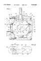
- FIG. 1is a sectional view of a top entry spherical plug type rotary full control valve that is constructed in accordance with the present invention.
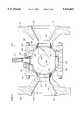
- FIG. 2is a sectional view taken along line 2--2 of FIG. 1.
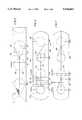
- FIG. 3is a sectional view of an alternative embodiment of the present invention in the form of a spherical rotary flow control valve that is constructed in accordance with the present invention.
- FIG. 4is a sectional view illustrating a spherical plug type flow control valve representing an alternative embodiment of the present invention wherein a valve ball is provided having a flowway that is of smaller dimension than the internal dimension of the connection flanges of the valve body.
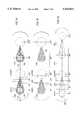
- FIG. 5is a schematic circumferential layout depicting the rotatable valve plug of the flow control valve mechanism of FIGS. 1-4 and showing the flow control slots in relation to the flowway of the rotary valve element.
- FIG. 6is a schematic circumferential layout illustrating flow control slots of the rotatable valve element of this invention, with the small extremities of the throttling slots being oppositely located with respect to the central axis of the flowway.
- FIG. 7is a schematic circumferential layout illustrating throttling slots of the rotatable flow control, valve of this invention, with the small extremities of the flow control slots being located centrally with respect to the central axis of the flowway.
- FIG. 8is a schematic circumferential layout illustrating an alternative embodiment of this invention depicting a rotatable plug valve element having multiple flow control slots which collectively establish efficient control of the flowing fluid.
- FIG. 9is a schematic circumferential layout illustrating an alternative embodiment of this invention depicting a rotatable valve element having multiple flow control passages defined by holes that are drilled or otherwise formed.
- FIG. 10is a schematic circumferential layout illustrating an alternative embodiment of this invention depicting a rotatable valve element having dual flow control ports.
- FIG. 11is a schematic circumferential layout illustrating an alternative embodiment of this invention depicting a rotatable plug valve element having contoured flow control slots.
- FIG. 12is a schematic circumferential layout illustrating an alternative embodiment of this invention depicting a rotatable valve element having contoured flow control slots and showing noise abatement and anti-cavitation trim being located in the contoured slots.
- FIG. 13is a schematic circumferential layout illustrating an alternative embodiment of this invention depicting a rotatable valve element having contoured flow control slots and showing noise abatement and anti-cavitation trim being located in the contoured slots and in the flowway.
- FIG. 14is a schematic circumferential layout illustrating an alternative embodiment of this invention depicting a rotatable valve element having contoured flow control slots and showing noise abatement and anti-cavitation trim being located in the contoured slots and in a portion of the flowway.
- FIG. 15is a schematic circumferential layout illustrating an alternative embodiment of this invention depicting a rotatable element having flow control passages formed in the rotatable valve element and defining both the flow control passages and the flowway thereof.
- FIG. 16is a pictorial sectional view of a rotary control valve constructed in accordance with this invention and showing the rotary valve element in its nearly closed flow controlling position and illustrating the magnitude of flow by the width of a flow arrow.
- FIG. 17is a pictorial sectional view similar to that of FIG. 16 and showing the rotary valve element in a more open flow controlling position as compared to FIG. 16.
- FIG. 18is a pictorial sectional view similar to that of FIGS. 15 and 16 and showing the rotary valve element in its fully open position.
- FIG. 19is a schematic circumferential layout view showing the ratio of flowway diameter to the rotary valve element diameter of 4.0 to 1.0.
- FIG. 20is a schematic circumferential layout view similar to that of FIG. 19 but showing a ratio of flowway diameter to the diameter of the rotary valve element of 2.0 to 1.0.
- a rotary flow control valve constructed in accordance with the present inventionis illustrated generally at 10 and incorporates a valve body shown generally at 12 having connection flanges 14 and 16 that permit the valve mechanism to be connected into a flow line, not shown.
- the valve body 12defines an internal valve chamber 18 within which is located a rotary plug or ball type valve element 20.
- the valve elementis provided with a trunnion 22 which is received by a trunnion bushing 24 located within an internal trunnion bore 26.
- valve element 20defines a valve stem 28 having a lower section 30 which is received by an upper bushing member 32 of a bushing receptacle 34 that is defined by a valve bonnet or closure member 36.
- the trunnion 22 and the valve stem 28are coaxial and define an axis of rotation 37 that intersects the longitudinal axis 39 of the valve body flow passage which is defined by the axially aligned inlet and outlet openings 54 and 56.
- the valve bonnetis typically secured to the valve body 12 by means of a plurality of bolts 38 or by any other suitable means of retention.
- the valve bonnetis sealed with respect to the valve body 12 by means of one or more circular sealing elements 40.
- a stem packing retainer 42is secured to the bonnet structure 36 about the valve stem 28 and functions to secure a packing member 44 within a packing chamber 46 thereof.
- bonnet structure 36removed from the valve body there is defined a bonnet opening 48 of sufficient dimension to permit upward extraction of the valve element 20 from the valve chamber 18.
- the bonnet or closure 36may simply be removed from the valve body to permit the internal movable components to be efficiently removed and replaced while the valve body 12 remains in the flow line.
- the valve body 12is provided internally with a pair of opposed internal seat recesses 50 and 52 which are defined concentrically about inlet and outlet flow passages 54 and 56 and which receive seat assemblies 58 and 60 that establish sealing engagement with the outer sealing surface 62 of the rotary valve element 20. Sealing between the seat assemblies and the valve body is accomplished by circular sealing elements 64 and 66 which are retained within appropriate circular seal grooves of the seat assemblies.
- the rotary valve element 20defines a flowway 68 which is in the form of a through bore defined about a longitudinal axis 70.
- the flowway 68is of substantially the same internal dimension as the internal passage sections 72 and 74 of the seat assemblies 58 and 60 and the internal dimension of the inlet and outlet passage sections 54 and 56.
- a through passage like the trim package 151 of FIG. 5is collectively defined through the valve mechanism which permits unobstructed flow of fluid therethrough.
- This straight through flow passagemay be of reduced dimension along its length to provide for controlled flow of fluid or to provide for the development of a desired pressure differential across the valve.
- the flowway of the valve elementmay be of equal dimension or the dimension of the flow passage defined by the valve body to ensure minimal pressure drop across the valve and, if desired, to permit objects such as line scrapers, pigs, cleaning balls, etc. to be passed through the valve mechanism under the influence of the flowing fluid.
- the rotary valve plug element 20is formed to define a pair of generally "V" shaped contoured throttling slots 76 and 78 which intersect the flowway 68 and which intersect a portion of the external annular sealing surface of the rotary valve element. As shown in FIG. 1 the throttling slots are at the greatest dimension thereof at their respective juncture with the flowway 68 and they gradually reduce in width and depth to the smallest dimensions thereof shown at 80 and 82.
- V-shaped contoured flow control slotsdefine bottom surfaces or lines 81 and 83 which are coextensive as shown or are oriented in parallel relation.
- opposed fluid blocking areas 84 and 86 of the valve elementfunction to block the flow of fluid through the valve.
- the flowway 68is disposed with its longitudinal axis 70 disposed in substantially normal relation with the longitudinal axis 39 about which the inlet and outlet passages and 54 and 56 are defined.
- the respective flow control slots 76 and 78Upon rotation of the valve element 20 about the axis of rotation 37, defined collectively by the valve stem 30 and trunnion 22, the respective flow control slots 76 and 78 will move into fluid communication with the flow passage of the valve, thus permitting fluid under pressure to be transmitted from the inlet flow passage 54 or 56 as the case may be through the upstream flow control slot, into the flowway of the valve element and thence through the downstream flow control slot to the downstream flow passage of the valve.
- the volume of fluid flow at a particular pressureis determined by the position of the respective flow control slots 76 and 78 with respect to the valve seat assemblies 58 and 60 which establish an effective flow port of a selected dimension.
- the flow control slots 76 and 78may contain anti-cavitation and noise abatement trim such as shown at 151 in FIG. 5, thus defining tortious flow paths through the flow control slots which will minimize cavitation and noise as is evident from FIGS. 12-15 the noise abatement and anti-cavitation trim may be located within the flowway of the rotary valve element as well.
- FIGS. 1 and 2movement of the rotary valve plug element 20 from the fully closed position shown in FIGS. 1 and 2 to the fully open position is accomplished by rotary valve movement of about 90°.
- This 90° rotational movementpermits the use of conventional 90° rotary valve actuators and thus permits a flow control valve mechanism of this nature to be provided to customers at relatively low cost.
- this rotary plug movementcan be in the range of from about 60° to about 130°.
- valve plug rotation in the range of about 90°is considered desirable for the reason that 90° valve actuators are readily available at nominal cost.
- FIG. 3an alternative embodiment of the present invention is shown which includes a valve body structure shown generally at 90 having an annular housing member 92 to which is connected body flanges 94 and 96 by means of bolts or threaded studs 98 and 100.
- the end members 94 and 96may be provided with connection flanges such as shown at 102 for bolted connection to a pipe flange, not shown or in the alternative, may be provided with a bolted or welded type flange structure 104 as suits the needs of the user.
- the connection flanges 102 and 104define inlet and outlet flow passages 106 and 108 to permit the transition of fluid through the valve mechanism.
- the central body section 92 and the end members 94 and 96 of the body structurecooperatively define an internal valve chamber 110 within which is received a rotary generally spherical plug or ball type flow control valve element 112.
- the rotary valve elementdefines an outer spherical sealing surface 114 which is intersected by a flowway 116 having a generally cylindrical wall 118 defined about a longitudinal axis 120.
- the spherical valve member 112is supported about an axis of rotation 122 by engagement with seat assemblies 124 and 126 which are respectively received within circular seat recesses 128 and 130 that are defined concentrically about a longitudinal axis 132 about which the flow passages 106 and 108 are also concentrically oriented.
- the spherical valve elementis further provided with an upstanding boss 134 definitely an internal stem drive receptacle 136 receiving the stem drive element 138 of a valve stem 140 to provide for a rotation of the valve element upon consequent rotation of the valve stem.
- the valve stemis sealed with respect to the valve body by means of a packing gland 142 having internal and external seals 144 and 146 respectively.
- valve mechanism of FIG. 3is shown in its dosed position with the flowway 116 oriented at substantially 90° out of aligned registry with the inlet and outlet flow passages 106 and 108.
- opposed blocking areas 148 and 150 of the spherical sealing surface 114are bound or circumscribed by sealing engagement with the respective circular seat assemblies 124 and 126 thereby preventing flow of fluid through the valve mechanism.
- a pair of contoured flow control slots 152 and 154are defined in the rotary valve member and extend from respective ends of the flowway 116 and circumferentially along the spherical sealing surface 114 to a location just outside the boundary of sealing engagement with the blocking surface 150.
- valve element 112is rotated more toward its open position the effective orifice dimension of the flow control slots increase according to the angular position of the valve element 112.
- flow control slotsmay also be provided with anti-cavitation and noise abatement trim as is mentioned above to minimize cavitation and noise as the result of high pressure fluid flow control.
- FIG. 4there is shown a sectional view of a rotary spherical flow control valve shown generally at 160 having a valve body shown generally at 161 and incorporating a central body section 162 to which is bolted end members 163 and 164 by a plurality of stud and nut assemblies 165.
- the end members of the valve bodydefine connection flanges 166 and 167 for bolted connection to pipe flanges of a flowline and define internal tapered sections 168 and 169 which form reducing flow passage sections typically having the same internal dimension at the inlet and outlet ends 170 and 171 as the internal dimension of the flowline into which the valve mechanism is connected.
- These reducing sectionsdefine reduced diameter flow ports 172 and 173 which have a diameter that is of significantly smaller dimension as compared to the dimension of the inlet and outlet ports 170 and 171.
- a rotatable valve member 174 having an outer spherical sealing surface 175is supported for rotation within a valve chamber 176 of the valve by an upper valve stem 177 and a lower trunnion 178 of the rotary valve member.
- the valve stem and trunnionare supported for rotation by bearing or bushing members 179 and 180.
- the valve stemextends externally of the valve chamber and is sealed relative to the central body section 162 by a packing gland 181.
- the rotary valve memberalso defines a straight through flowway 182 of a dimension substantially corresponding to the dimension of the restricted flow ports 172 and 173.
- the rotary valve memberis sealed with respect to the valve body structure by means of a pair of seat assemblies 183 and 184 which are respectively retained within internal seat recesses defined within the respective end members.
- the rotary valve member 174defines a pair of contoured flow control slots 185 which intersect the flowway 182 near opposite ends thereof.
- These contoured flow control slotsare of the configuration shown in FIG. 5 and for purposes of noise and cavitation control may include noise abatement and anti-cavitation trim such as is described above and as further shown in connection with the layout illustrations of FIGS. 13-15.
- the angular relation of rotational valve movement relative to the open and closed positions of the throttling valve mechanism of FIG. 4is shown diagrammatically in the layout illustration of FIG. 5.
- the closed positionis shown at 0° rotation in FIG. 5.
- the small dimension 156 of the contoured throttling slot 152 at this pointis located very close to the circular boundary 125 which is defined by sealing engagement of the seat assembly with the sealing surface of the rotary valve element so that the blocking area 150 of the valve element is out of communication of the flow control slot.
- the small dimension 156 of the flow control slotwill cross the seal boundary 125 thereby permitting fluid communication between the flow passage and the flow control slot.
- the rotary position of the valve elementcan simply be reversed to permit fluid flushing of the accumulated solids from the torturous flow paths of the trim package.
- the trim of the upstream and downstream flow control slotscan differ if desired so that complete flow control can occur upon traverse of fluid completely through the flow control slots and the valve ball flowway.
- the valve mechanismcan be of unidirectional character.
- the inlet and outlet flow control slotsmay also be of differing dimension if desired.
- FIGS. 6-15a number of different rotary plug type flow control valve layouts are depicted which illustrate differing contoured flow control slot or passage configuration.
- the flow control slots or passagesare provided to define controlled flow of fluid through the valve mechanism at different rotational positions thereof and noise abatement and anti-cavitation trim is provided to assist in flow control.
- the rotatable valve element depicted in the layout illustrationdefines opposed contoured flow control or throttling slots 186 and 187 that taper in both width and depth along the length thereof from a large slot dimension at the intersection of the throttling slot with the respective end of the flowway as shown at 190 and 191 to a small dimension as shown at 192 and 193.
- various angular rotary valve element positionsare shown, illustrating rotational movement of the valve element from 0° to 90° at the left hand portion of the Figure and further illustrating the opposite end of the flowway 191 being located at 180°.
- the external annular sealing surface 194 of the valve plugdefines blocking surface areas 195 and 196 located at 90° and 270° respectively.
- tapered flow control slots 187 and 188are oppositely oriented with respect to the longitudinal axis 197. Such opposite orientation of the contoured flow control slots or passages provides the rotary valve member with exceptional strength. Further, such opposite orientation of the flow control slots or passages permits the flow control slots to be of slightly greater length as compared to the flow control slots of FIG. 7.
- FIG. 7is a valve plug layout illustration similar to that of FIG. 5 and showing throttling slots or passages 198 and 199 that are oriented in alignment with the horizontal axis 200 thereof.
- a valve plug layoutis shown depicting an annular plug sealing surface 201 having flowway extremities 202 and 203.
- Flow control passage or slot means 204 and 205are defined by multiple, generally parallel external slots or passages which establish flow control communication with the flowway of the valve element.
- the external annular sealing surface 201 of the rotary valve elementmay be of spherical, tapered or straight configuration as desired and includes blocking surface areas 206 and 207 illustrating seal location at the closed position of the valve.
- FIG. 9shows a rotary valve element having an external sealing surface 208 which is intersected by the flowway at 209 and 210. Throttling or flow control is achieved by a plurality of flow control ports or passages 211 and 212 respectively which may be in the form of holes that are drilled or otherwise formed in the rotary valve element. Blocking surface areas 213 and 214 of the external sealing surface 208 are encompassed by the valve seats of the valve; mechanism at the fully closed position of the valve element.
- valve element layout illustrationdefines an annular sealing surface 215 which is intersected at 216 and 218 by the flowway of the valve element.
- Flow control or throttling passages 220 and 222are shown which are positioned in registry with the flow passages of the valve to provide for precise control of fluid flow.
- the valve flowwayis in registry with the flow passages of the valve body flow through the flow control valve mechanism is unobstructed so that the pressure drop across is virtually the same as the pressure drop across an open full ported ball valve. If the flowway is of the same or greater dimension as compared with the dimension of the flow passage of the valve body line cleaning devices may be passed through the throttling valve in its fully open condition.
- the sealing surface 214defines blocking areas 224 and 226 which are encompassed by the seat assemblies of the valve in its fully closed condition of the valve.
- valve element layoutdepicts an annular sealing surface 228 which is intersected at 230 and 232 by the flowway of the valve element. Throttling or flow control is accomplished by contoured flow control slots or passages 234 and 236 which are shown oriented in alignment with the longitudinal axis 238 of the flowway. It should be borne in mind that these contoured external slots or throttling passages may be oriented in misaligned relation with the longitudinal axis in the same manner as shown above in FIG. 6.
- the sealing surface 228also defines blocking areas 240 and 242 which are oriented 180° apart and which are encompassed by the seat assemblies of the valve in the fully closed position of the valve element.
- the noise abatement and anti-cavitation trim for the rotary flow control valve mechanism of this inventionmay be located solely in the contoured flow controlling slots or it may be located both in the flow controlling slots and in the flowway of the rotary valve element or in a portion of the flowway.
- the layout illustrationidentifies an annular sealing surface 244 which is intersected by the ends 246 and 248 of a flowway 250.
- the sealing surface of the rotary valve elementdefines blocking areas 252 and 254 which are circumscribed by sealing contact with the seat assemblies in the closed position of the rotary valve element.
- the rotary valve elementis provided with a pair of contoured flow control slots 256 and 258 having noise abatement and anti-cavitation trim 260 and 262 located respectively therein and defining a trim package.
- the trim packagemay be defined by a plurality of layers of perforate trim material, with the layers being of differing dimension and cooperatively oriented so as to establish a torturous flow path which causes a pressure drop between trim layers. Thus, there is developed pressure drop across the trim as the flowing fluid passes into or from the respective trim packages. This "double" pressure drop has been found quite effective in both the reduction of noise and cavitation.
- the trim packagesmay be defined by individual layers of trim material which are welded or otherwise fixed in place or, in the alternative, the trim package may be a unitary structure which is retained in assembly with the rotary valve element in any suitable manner.
- the rotary valve element structureis identical to that of FIG. 12, with the exception that the noise abatement and anti-cavitation package shown at 264 and 266 is located not only in the contoured flow control slots but also in the flow ports 250 and 251.
- the purpose of the trim package as shown in FIG. 13is essentially the same as described above in connection with FIG. 12, the exception being that the flowway 250 in the case of FIG. 13 is partially closed by the trim. In this case it is not possible to pass any object through the flowway.
- the rotary valve element structureis essentially the same as described above in connection with FIGS. 12 and 13, with the exception that alternative noise abatement and anti-cavitation trim packages 268 and 270 are provided which fill at least a substantial portion of the contoured flow control slots and also fill a portion of the flowway 250.
- the trim packages and 268 and 270leave a central unobstructed opening as shown at 272 and 274 through which fluid may flow in unobstructed manner.
- the rotary valve element constructionis essentially the same as shown in FIGS. 12-15 in this case however the flowway is defined in part by a plurality of passages shown at 276 and 278. Likewise, similar drilled or otherwise formed passages 280 and 282 are provided to define the flow controlling passage means of the rotary vane element and also to minimize noise and cavitation.
- FIGS. 16-18the design of the tapered or V-shaped contoured flow control slots permit full opening and complete shutoff of the flow control valve mechanism in rotary vane movement of about 90°. Further the vane mechanism defines a path that extends straight through the rotary valve element at any position thereof.
- the rotary valve element 284is shown in position to define a restricted straight through path 286 which intersects the flowway 288. The magnitude of fluid flow is thus depicted by the width of the flow arrow 287.
- FIG. 17the rotary valve element is shown rotated to a more open position as compared with FIG. 16 and thus defines a straight through path 286a of increased dimension as compared to FIG. 16.
- the magnitude of fluid flow through the valveis in this case defined by the broader width of the flow arrow 287a.
- the flowway 288When fully open as shown in FIG. 18 the flowway 288 is in registry with the inlet and outlet passages of the valve body so that full flow occurs as indicated by the width of the flow arrow 287b. In this full open position the pressure drop across the valve mechanism is nearly the same as in a length of equal diameter pipe and full unobstructed and uncontrolled flow is permitted through the control valve.
- the length of the contoured flow control slots in relation to the flowway diametercan be efficiently selected to provide the rangeability that is desired by the user.
- the diameter of the rotary valve elementwill be established by the ratio of contoured flow control slot length to flowway diameter.
- the length of the flow control slotswill also increase. For example, a rotary valve element having a 6" diameter flowway with a 2.0 to 1.0 ratio of flow control slot length to flowway diameter would result in a rotary valve element diameter of 24".
- the length of the contoured flow control slotsbecomes greater, giving greater flow control rangeability for the same amount of rotation of the rotary valve element.
- the circumferential length of the valve element 290is depicted in the schematic layout illustration.
- the length of the contoured flow control slots 292 and 294is depicted as graphically illustrated in relation to the diameter of the flowway 296.
- the resulting circumference of the rotary valve elementis depicted by the overall length of the schematic layout of FIG. 19.
- FIG. 20The schematic layout of a rotary valve element having a slot length with a 2.0 to 1.0 ratio is shown in FIG. 20.
- the valve element 298defines contoured flow control slots 300 and 302 that are much shorter as compared with flow control slots 292 and 294 of FIG. 19 even though the flowway 304 is of the same dimension. Consequently, the valve element of FIG. 20 will be of smaller diameter as indicated by the overall length of the circumferential layout.
- the flowway diameter and the selected length of the contoured flow control slotswill determine the diameter of the rotary valve element.
- the usercan thus choose for any given flowway diameter the flow control rangeability that is desired and weight these factors in light of the resulting valve size. If a maximum valve size is necessary the rangeability for that valve size can be efficiently established.
Landscapes
- Engineering & Computer Science (AREA)
- General Engineering & Computer Science (AREA)
- Mechanical Engineering (AREA)
- Details Of Valves (AREA)
- Taps Or Cocks (AREA)
Abstract
Description
Claims (5)
Priority Applications (1)
| Application Number | Priority Date | Filing Date | Title |
|---|---|---|---|
| US08/257,104US5524863A (en) | 1994-06-08 | 1994-06-08 | Quarter turn rotatable flow control valve |
Applications Claiming Priority (1)
| Application Number | Priority Date | Filing Date | Title |
|---|---|---|---|
| US08/257,104US5524863A (en) | 1994-06-08 | 1994-06-08 | Quarter turn rotatable flow control valve |
Publications (1)
| Publication Number | Publication Date |
|---|---|
| US5524863Atrue US5524863A (en) | 1996-06-11 |
Family
ID=22974906
Family Applications (1)
| Application Number | Title | Priority Date | Filing Date |
|---|---|---|---|
| US08/257,104Expired - LifetimeUS5524863A (en) | 1994-06-08 | 1994-06-08 | Quarter turn rotatable flow control valve |
Country Status (1)
| Country | Link |
|---|---|
| US (1) | US5524863A (en) |
Cited By (67)
| Publication number | Priority date | Publication date | Assignee | Title |
|---|---|---|---|---|
| US5819789A (en)* | 1995-09-14 | 1998-10-13 | American Standard Inc. | Water valve for a sanitary fitting |
| EP0864788A4 (en)* | 1996-09-30 | 1999-07-07 | Seikisui Chemical Co Ltd | Ball valve |
| US5954273A (en)* | 1997-04-22 | 1999-09-21 | Minnesota Mining And Manufacturing Company | Spray assembly for high viscosity materials |
| US6520481B2 (en) | 2000-09-15 | 2003-02-18 | Uwe Harneit | Linearly regulated gas valve for gas burners |
| US20030196709A1 (en)* | 2002-04-23 | 2003-10-23 | Mendoza Michael J. | Compressed air flow controller |
| US20030205685A1 (en)* | 2002-02-13 | 2003-11-06 | Whang Cheol H. | Finite control hydraulic valve |
| US6644625B1 (en)* | 2000-08-11 | 2003-11-11 | L. R. Nelson | Pistol grip hose nozzle with proportional flow control |
| US20030236508A1 (en)* | 2002-06-24 | 2003-12-25 | Cull Laurence J. | Adjustable fluid flow resistor cassette |
| US6675832B1 (en)* | 2003-05-07 | 2004-01-13 | Control Components, Inc. | Blowdown valve |
| EP1473498A1 (en)* | 2003-04-30 | 2004-11-03 | Pibiviesse S.p.A. | Valve |
| US20040244851A1 (en)* | 2003-06-05 | 2004-12-09 | Joseph Thomas Anthony | Rotary valve |
| US20050082506A1 (en)* | 2003-10-17 | 2005-04-21 | Caprera Brian J. | Dual segment ball valve |
| US20050150559A1 (en)* | 2004-01-12 | 2005-07-14 | Kwon Hyuk J. | Apparatus and method for controlling exhaust pressure in semiconductor manufacturing |
| US20050166964A1 (en)* | 2004-01-30 | 2005-08-04 | Scania Cv Ab (Publ) | Valve |
| EP1610043A1 (en)* | 2004-06-23 | 2005-12-28 | "Farm & Garten-STM" Vetriebs GmbH | Valve for fluid |
| US20070034267A1 (en)* | 2005-08-09 | 2007-02-15 | Spx Corporation | Valve assembly and method with slotted plates and spherical ball plug |
| WO2007041892A1 (en)* | 2005-10-08 | 2007-04-19 | Yongsheng Song | A shut-off valve |
| US20070164517A1 (en)* | 2006-01-14 | 2007-07-19 | Caprera Brian J | Seal cartridge control valve |
| US20080054208A1 (en)* | 2006-09-06 | 2008-03-06 | Groves Frank W | Elbow plug external sleeve valve |
| US20080315142A1 (en)* | 2007-06-19 | 2008-12-25 | Snecma | Long-stroke regulator valve with a stop function |
| US20090199905A1 (en)* | 2006-06-12 | 2009-08-13 | Tour & Andersson Ab | Regulating valve with maintained regulating characteristic at different kv-values within one and the same valve |
| US20090302259A1 (en)* | 2006-04-13 | 2009-12-10 | Vir Valvoindustria Ing. Rizzio - S.P.A. | Ball for valves and production method |
| US20110120578A1 (en)* | 2009-11-23 | 2011-05-26 | Lockhart Douglas Lloyd | Manifold for refrigeration system |
| KR101076269B1 (en) | 2009-10-08 | 2011-10-26 | 대우조선해양 주식회사 | Apparatus for diminishing flash gas of a liquefied gas carrier |
| KR101147363B1 (en)* | 2009-10-08 | 2012-05-22 | 대우조선해양 주식회사 | Control valve system capable of operating in liquid freight |
| US8262546B1 (en)* | 2007-09-16 | 2012-09-11 | Charles Mark Lashinske | Inertial weight for physical conditioning |
| US20120318525A1 (en)* | 2011-06-15 | 2012-12-20 | Baker Hughes Incorporated | Tubular valving system, body and method of opening |
| CN103028578A (en)* | 2012-12-21 | 2013-04-10 | 中国石油大学(北京) | Three-way ball valve beneficial to cleaning pipelines with branch pipelines and pipe cleaning method |
| WO2014011922A1 (en)* | 2012-07-11 | 2014-01-16 | Illinois Tool Works Inc. | Thermostat valve |
| CN103851219A (en)* | 2012-11-28 | 2014-06-11 | 多玛两合有限公司 | Adjusting valve used for adjusting hydraulic volume flow rate |
| US20140216763A1 (en)* | 2012-02-10 | 2014-08-07 | Halliburton Energy Services, Inc. | Debris Anti-Compaction System for Ball Valves |
| US20140264127A1 (en)* | 2013-03-14 | 2014-09-18 | Denso Corporation | Valve device |
| CN104105910A (en)* | 2011-11-30 | 2014-10-15 | 汉拿伟世通空调有限公司 | Ball valves with internal seals especially used in motor vehicle refrigerant circuits |
| EP2868951A1 (en)* | 2013-10-30 | 2015-05-06 | Kobelco Construction Machinery Co., Ltd. | Valve and construction machine with the same |
| US20150129788A1 (en)* | 2013-11-14 | 2015-05-14 | Charles C. Hansen, III | Ball valve for cold fluids |
| US20150137017A1 (en)* | 2013-11-15 | 2015-05-21 | Ivenix, Inc. | Fluid flow regulator assembly |
| US20150167660A1 (en)* | 2013-12-17 | 2015-06-18 | Trane International Inc. | Fluid valve |
| US20150210417A1 (en)* | 2012-08-10 | 2015-07-30 | Tetra Laval Holdings & Finance S.A. | Shutter for a valve and corresponding valve for controlling an air flow and relative valve |
| CN105276212A (en)* | 2014-07-23 | 2016-01-27 | 天津明贤科技有限公司 | A proportional regulating valve |
| CN106763860A (en)* | 2016-12-14 | 2017-05-31 | 石森林 | Spherical valve core |
| US20170363223A1 (en)* | 2014-08-15 | 2017-12-21 | Illinois Tool Works Inc. | Thermostat valve and method for operating a thermostat valve |
| CN107676501A (en)* | 2017-11-23 | 2018-02-09 | 天津市卡尔斯阀门有限公司 | A kind of antiscale valve |
| US9990849B2 (en) | 2015-02-12 | 2018-06-05 | Robert Bosch Gmbh | Method and device for ascertaining a parking position for a vehicle |
| DE102017101208A1 (en) | 2017-01-23 | 2018-07-26 | Hanon Systems | Valve for a heat pump system in a vehicle |
| US20180263180A1 (en)* | 2015-09-28 | 2018-09-20 | Precision Planting Llc | Systems and devices for controlling and monitoring liquid applications of agricultural fields |
| US20180283579A1 (en)* | 2017-04-04 | 2018-10-04 | Schaeffler Technologies AG & Co. KG | Variations of fluid opening geometry for rotary valve body |
| CN108953653A (en)* | 2017-05-24 | 2018-12-07 | 浙江三花汽车零部件有限公司 | A kind of motor-driven valve |
| RU2681726C1 (en)* | 2018-05-03 | 2019-03-12 | Вадим Михайлович Сакизчи | Flow control valve |
| CN109826974A (en)* | 2019-02-20 | 2019-05-31 | 徐国华 | A kind of V-type ball valve |
| US10420600B2 (en) | 2016-02-02 | 2019-09-24 | Arthrex, Inc. | Ablation device with variable aspiration control system |
| US20190346049A1 (en)* | 2018-05-14 | 2019-11-14 | Cooler Master Co.,Ltd. | Control valve |
| US10480683B2 (en)* | 2017-10-10 | 2019-11-19 | Metso Flow Control Oy | Valve and closure member |
| JP2021046875A (en)* | 2019-09-17 | 2021-03-25 | 三浦工業株式会社 | Ball valve |
| IT202000004282A1 (en)* | 2020-03-02 | 2021-09-02 | Nuovo Pignone Tecnologie Srl | ADJUSTABLE DAMPING VALVE |
| US11118699B2 (en)* | 2013-12-02 | 2021-09-14 | Vincent Edwards | Hydraulic switch |
| US20210341235A1 (en)* | 2020-05-01 | 2021-11-04 | Mikuni Corporation | Valve device, cooling water control device, and cooling water circuit |
| CN114439974A (en)* | 2018-04-05 | 2022-05-06 | 翰昂汽车零部件有限公司 | Device for regulating the distribution and flow of a fluid in a fluid circulation circuit |
| US20220186857A1 (en)* | 2020-12-11 | 2022-06-16 | Dresser, Llc | Reducing noise in ball valves |
| US20220316605A1 (en)* | 2021-03-31 | 2022-10-06 | Jason Patti | Valve apparatus |
| US20220325806A1 (en)* | 2021-04-08 | 2022-10-13 | Denso Corporation | Valve device |
| CN115234675A (en)* | 2022-08-04 | 2022-10-25 | 郭娅 | Three-dimensional throttling device with variable flow channel and throttling method of fluid |
| US20220356951A1 (en)* | 2021-05-07 | 2022-11-10 | Control Components, Inc. | Ball control valves having three-dimensional tortuous path flowpaths |
| DE102021131113A1 (en) | 2021-11-26 | 2023-06-01 | Hanon Systems | Ball valve with flow-optimized ball passage channel |
| DE102021132184A1 (en) | 2021-12-07 | 2023-06-07 | Hanon Systems | Device for controlling a flow and expanding a fluid |
| CN116557564A (en)* | 2022-01-27 | 2023-08-08 | 浙江恒森实业集团有限公司 | Plug valves, refrigerant control devices for motor vehicle air conditioners, motor vehicle air conditioners and motor vehicle |
| US20240035578A1 (en)* | 2022-07-27 | 2024-02-01 | Otto Egelhof Gmbh & Co. Kg | Ball valve |
| US20250020220A1 (en)* | 2023-07-12 | 2025-01-16 | Vadim Mikhailovich SAKIZCHI | Flow control valve |
Citations (23)
| Publication number | Priority date | Publication date | Assignee | Title |
|---|---|---|---|---|
| US2510514A (en)* | 1946-05-08 | 1950-06-06 | Mueller Co | Valve |
| CH340681A (en)* | 1955-04-18 | 1959-08-31 | J S Schatt Gmbh Armaturenfabri | Drain valve with fine adjustment |
| US3347517A (en)* | 1964-12-09 | 1967-10-17 | Scaramucci Domer | Valve and seal |
| US3403887A (en)* | 1966-11-28 | 1968-10-01 | Honeywell Inc | Ball valve |
| US3542338A (en)* | 1968-07-29 | 1970-11-24 | Domer Scaramucci | Throttling valve |
| US3542337A (en)* | 1968-07-29 | 1970-11-24 | Domer Scaramucci | Throttling valve with protected seals |
| US3773291A (en)* | 1970-03-30 | 1973-11-20 | Fischer & Porter Co | Ball valves |
| US3786837A (en)* | 1971-11-26 | 1974-01-22 | Valspar Corp | Filling apparatus |
| US3880191A (en)* | 1974-03-21 | 1975-04-29 | Hans D Baumann | Rotary multiport throttling valve |
| US3883113A (en)* | 1974-03-29 | 1975-05-13 | Acf Ind Inc | Fluid control ball valve structure for throttling service |
| US3985150A (en)* | 1975-06-03 | 1976-10-12 | Kamyr Valves, Inc. | Ball valve for valving abrasive fluids |
| US4164343A (en)* | 1977-09-12 | 1979-08-14 | Henry Voyt Machine Co. Inc. | Eccentric ball type valve |
| US4212321A (en)* | 1979-04-09 | 1980-07-15 | J. R. Butler | Low noise rotary control valve |
| US4364409A (en)* | 1980-08-18 | 1982-12-21 | Jones James S | Fluid flow control device |
| US4364415A (en)* | 1980-06-27 | 1982-12-21 | Neles Oy | Method for attenuating a medium flow passing through a valve and a valve for applying the method |
| US4401238A (en)* | 1980-04-16 | 1983-08-30 | Marchadour Jean Charles | Devices used for filling containers |
| US4530375A (en)* | 1979-01-10 | 1985-07-23 | Roger Bey | Attenuating rotating valve |
| US4540025A (en)* | 1983-03-28 | 1985-09-10 | Grove Valve And Regulator Company | Throttling ball valve |
| US4665946A (en)* | 1985-08-30 | 1987-05-19 | Daniel Industries, Inc. | Rotary control valves with pressure-reducing means |
| US4881718A (en)* | 1987-11-27 | 1989-11-21 | Jamesbury Corporation | Ball control valve |
| US4889163A (en)* | 1987-02-05 | 1989-12-26 | Ab Tore J Hedback | Valve assembly |
| US5070909A (en)* | 1990-06-11 | 1991-12-10 | Davenport Robert G | Low recovery rotary control valve |
| US5287889A (en)* | 1992-09-22 | 1994-02-22 | Leinen Christopher M | Low-noise rotary control valve |
- 1994
- 1994-06-08USUS08/257,104patent/US5524863A/ennot_activeExpired - Lifetime
Patent Citations (24)
| Publication number | Priority date | Publication date | Assignee | Title |
|---|---|---|---|---|
| US2510514A (en)* | 1946-05-08 | 1950-06-06 | Mueller Co | Valve |
| CH340681A (en)* | 1955-04-18 | 1959-08-31 | J S Schatt Gmbh Armaturenfabri | Drain valve with fine adjustment |
| US3347517A (en)* | 1964-12-09 | 1967-10-17 | Scaramucci Domer | Valve and seal |
| US3403887A (en)* | 1966-11-28 | 1968-10-01 | Honeywell Inc | Ball valve |
| US3542338A (en)* | 1968-07-29 | 1970-11-24 | Domer Scaramucci | Throttling valve |
| US3542337A (en)* | 1968-07-29 | 1970-11-24 | Domer Scaramucci | Throttling valve with protected seals |
| US3773291A (en)* | 1970-03-30 | 1973-11-20 | Fischer & Porter Co | Ball valves |
| US3786837A (en)* | 1971-11-26 | 1974-01-22 | Valspar Corp | Filling apparatus |
| US3880191A (en)* | 1974-03-21 | 1975-04-29 | Hans D Baumann | Rotary multiport throttling valve |
| US3883113A (en)* | 1974-03-29 | 1975-05-13 | Acf Ind Inc | Fluid control ball valve structure for throttling service |
| US3985150A (en)* | 1975-06-03 | 1976-10-12 | Kamyr Valves, Inc. | Ball valve for valving abrasive fluids |
| US4164343A (en)* | 1977-09-12 | 1979-08-14 | Henry Voyt Machine Co. Inc. | Eccentric ball type valve |
| US4610273A (en)* | 1979-01-10 | 1986-09-09 | Roger Bey | Attenuated rotating valve |
| US4530375A (en)* | 1979-01-10 | 1985-07-23 | Roger Bey | Attenuating rotating valve |
| US4212321A (en)* | 1979-04-09 | 1980-07-15 | J. R. Butler | Low noise rotary control valve |
| US4401238A (en)* | 1980-04-16 | 1983-08-30 | Marchadour Jean Charles | Devices used for filling containers |
| US4364415A (en)* | 1980-06-27 | 1982-12-21 | Neles Oy | Method for attenuating a medium flow passing through a valve and a valve for applying the method |
| US4364409A (en)* | 1980-08-18 | 1982-12-21 | Jones James S | Fluid flow control device |
| US4540025A (en)* | 1983-03-28 | 1985-09-10 | Grove Valve And Regulator Company | Throttling ball valve |
| US4665946A (en)* | 1985-08-30 | 1987-05-19 | Daniel Industries, Inc. | Rotary control valves with pressure-reducing means |
| US4889163A (en)* | 1987-02-05 | 1989-12-26 | Ab Tore J Hedback | Valve assembly |
| US4881718A (en)* | 1987-11-27 | 1989-11-21 | Jamesbury Corporation | Ball control valve |
| US5070909A (en)* | 1990-06-11 | 1991-12-10 | Davenport Robert G | Low recovery rotary control valve |
| US5287889A (en)* | 1992-09-22 | 1994-02-22 | Leinen Christopher M | Low-noise rotary control valve |
Cited By (120)
| Publication number | Priority date | Publication date | Assignee | Title |
|---|---|---|---|---|
| US5819789A (en)* | 1995-09-14 | 1998-10-13 | American Standard Inc. | Water valve for a sanitary fitting |
| EP0864788A4 (en)* | 1996-09-30 | 1999-07-07 | Seikisui Chemical Co Ltd | Ball valve |
| US6021812A (en)* | 1996-09-30 | 2000-02-08 | Sekisui Kagaku Kogyo Kabushiki Kaisha & Ichinose Co., Ltd. | Ball plug valve |
| US5954273A (en)* | 1997-04-22 | 1999-09-21 | Minnesota Mining And Manufacturing Company | Spray assembly for high viscosity materials |
| US6644625B1 (en)* | 2000-08-11 | 2003-11-11 | L. R. Nelson | Pistol grip hose nozzle with proportional flow control |
| US6520481B2 (en) | 2000-09-15 | 2003-02-18 | Uwe Harneit | Linearly regulated gas valve for gas burners |
| US20030205685A1 (en)* | 2002-02-13 | 2003-11-06 | Whang Cheol H. | Finite control hydraulic valve |
| US20030196709A1 (en)* | 2002-04-23 | 2003-10-23 | Mendoza Michael J. | Compressed air flow controller |
| US6986361B2 (en)* | 2002-04-23 | 2006-01-17 | Mendoza Michael J | Compressed air flow controller |
| US6752795B2 (en)* | 2002-06-24 | 2004-06-22 | Bausch & Lomb Incorporated | Adjustable fluid flow resistor cassette |
| US20030236508A1 (en)* | 2002-06-24 | 2003-12-25 | Cull Laurence J. | Adjustable fluid flow resistor cassette |
| EP1473498A1 (en)* | 2003-04-30 | 2004-11-03 | Pibiviesse S.p.A. | Valve |
| US20040217312A1 (en)* | 2003-04-30 | 2004-11-04 | Antonio Corbetta | Regulation valve |
| CN100378385C (en)* | 2003-04-30 | 2008-04-02 | 皮比维耶斯股份公司 | Adjusting valve |
| US7044436B2 (en) | 2003-04-30 | 2006-05-16 | Pibiviesse S.P.A. | Regulation valve |
| US6675832B1 (en)* | 2003-05-07 | 2004-01-13 | Control Components, Inc. | Blowdown valve |
| US20040244851A1 (en)* | 2003-06-05 | 2004-12-09 | Joseph Thomas Anthony | Rotary valve |
| US7013917B2 (en) | 2003-06-05 | 2006-03-21 | Joseph Iii Thomas Anthony | Rotary valve |
| JP4884226B2 (en)* | 2003-10-17 | 2012-02-29 | ドレッサ、インク | Dual segment ball valve |
| CN100380030C (en)* | 2003-10-17 | 2008-04-09 | 德雷瑟股份有限公司 | Double-part ball valve |
| US6981691B2 (en) | 2003-10-17 | 2006-01-03 | Dresser, Inc. | Dual segment ball valve |
| WO2005040655A1 (en)* | 2003-10-17 | 2005-05-06 | Dresser, Inc. | Dual segment ball valve |
| US20050082506A1 (en)* | 2003-10-17 | 2005-04-21 | Caprera Brian J. | Dual segment ball valve |
| US7455076B2 (en)* | 2004-01-12 | 2008-11-25 | Samsung Electronics Co., Ltd. | Apparatus and method for controlling exhaust pressure in semiconductor manufacturing |
| US20050150559A1 (en)* | 2004-01-12 | 2005-07-14 | Kwon Hyuk J. | Apparatus and method for controlling exhaust pressure in semiconductor manufacturing |
| US20050166964A1 (en)* | 2004-01-30 | 2005-08-04 | Scania Cv Ab (Publ) | Valve |
| US7322559B2 (en)* | 2004-01-30 | 2008-01-29 | Scania Cv Ab (Publ) | Plug valve having high flow resolution |
| EP1610043A1 (en)* | 2004-06-23 | 2005-12-28 | "Farm & Garten-STM" Vetriebs GmbH | Valve for fluid |
| US7234488B2 (en)* | 2005-08-09 | 2007-06-26 | Spx Corporation | Valve assembly and method with slotted plates and spherical ball plug |
| CN101243274B (en)* | 2005-08-09 | 2010-12-01 | Spx公司 | Valve assembly and method with grooved plate and spherical plug |
| WO2007021643A1 (en)* | 2005-08-09 | 2007-02-22 | Spx Corporation | Valve assembly and method with slotted plates and spherical ball plug |
| US20070034267A1 (en)* | 2005-08-09 | 2007-02-15 | Spx Corporation | Valve assembly and method with slotted plates and spherical ball plug |
| EP1922502A4 (en)* | 2005-08-09 | 2013-01-09 | Spx Corp | VALVE ASSEMBLY AND METHOD WITH CRYSTAL PLATES AND SPHERICAL BALL VALVE |
| US20080251750A1 (en)* | 2005-10-08 | 2008-10-16 | Yongsheng Song | Valve for Fluids Containing Solid Particles or Liquid Drops |
| CN101405526B (en)* | 2005-10-08 | 2012-08-22 | 宋永生 | Valve closing member |
| WO2007041892A1 (en)* | 2005-10-08 | 2007-04-19 | Yongsheng Song | A shut-off valve |
| US7726339B2 (en) | 2006-01-14 | 2010-06-01 | Dresser, Inc. | Seal cartridge control valve |
| US20070164517A1 (en)* | 2006-01-14 | 2007-07-19 | Caprera Brian J | Seal cartridge control valve |
| US20090302259A1 (en)* | 2006-04-13 | 2009-12-10 | Vir Valvoindustria Ing. Rizzio - S.P.A. | Ball for valves and production method |
| US8166994B2 (en)* | 2006-04-13 | 2012-05-01 | Vir Valvoindustria Ing. Rizzio—S.p.A. | Ball for valves and production method |
| US20090199905A1 (en)* | 2006-06-12 | 2009-08-13 | Tour & Andersson Ab | Regulating valve with maintained regulating characteristic at different kv-values within one and the same valve |
| US7921867B2 (en) | 2006-09-06 | 2011-04-12 | Olmsted Products Co. | Elbow plug external sleeve valve |
| US20080054208A1 (en)* | 2006-09-06 | 2008-03-06 | Groves Frank W | Elbow plug external sleeve valve |
| US8371553B2 (en)* | 2007-06-19 | 2013-02-12 | Snecma | Long-stroke regulator valve with a stop function |
| US20080315142A1 (en)* | 2007-06-19 | 2008-12-25 | Snecma | Long-stroke regulator valve with a stop function |
| US8262546B1 (en)* | 2007-09-16 | 2012-09-11 | Charles Mark Lashinske | Inertial weight for physical conditioning |
| KR101147363B1 (en)* | 2009-10-08 | 2012-05-22 | 대우조선해양 주식회사 | Control valve system capable of operating in liquid freight |
| KR101076269B1 (en) | 2009-10-08 | 2011-10-26 | 대우조선해양 주식회사 | Apparatus for diminishing flash gas of a liquefied gas carrier |
| US8844567B2 (en)* | 2009-11-23 | 2014-09-30 | Douglas Lloyd LOCKHART | Manifold for refrigeration system |
| US20110120578A1 (en)* | 2009-11-23 | 2011-05-26 | Lockhart Douglas Lloyd | Manifold for refrigeration system |
| US20120318525A1 (en)* | 2011-06-15 | 2012-12-20 | Baker Hughes Incorporated | Tubular valving system, body and method of opening |
| US20140353536A1 (en)* | 2011-11-30 | 2014-12-04 | Halla Visteon Climate Control Corp. | Ball valve with internal seal arrangement, in particular for use in motor vehicle refrigerant circuits |
| CN104105910A (en)* | 2011-11-30 | 2014-10-15 | 汉拿伟世通空调有限公司 | Ball valves with internal seals especially used in motor vehicle refrigerant circuits |
| US9328584B2 (en)* | 2012-02-10 | 2016-05-03 | Halliburton Energy Services, Inc. | Debris anti-compaction system for ball valves |
| US20140216763A1 (en)* | 2012-02-10 | 2014-08-07 | Halliburton Energy Services, Inc. | Debris Anti-Compaction System for Ball Valves |
| WO2014011922A1 (en)* | 2012-07-11 | 2014-01-16 | Illinois Tool Works Inc. | Thermostat valve |
| CN104685275A (en)* | 2012-07-11 | 2015-06-03 | 伊利诺斯工具制品有限公司 | Thermostat valve |
| US9951878B2 (en) | 2012-07-11 | 2018-04-24 | Illinois Tool Works Inc. | Thermostat valve |
| US10301050B2 (en)* | 2012-08-10 | 2019-05-28 | Tetra Laval Holdings & Finance S.A. | Shutter for a valve and corresponding valve for controlling an air flow and relative valve |
| US20150210417A1 (en)* | 2012-08-10 | 2015-07-30 | Tetra Laval Holdings & Finance S.A. | Shutter for a valve and corresponding valve for controlling an air flow and relative valve |
| CN103851219A (en)* | 2012-11-28 | 2014-06-11 | 多玛两合有限公司 | Adjusting valve used for adjusting hydraulic volume flow rate |
| CN103028578A (en)* | 2012-12-21 | 2013-04-10 | 中国石油大学(北京) | Three-way ball valve beneficial to cleaning pipelines with branch pipelines and pipe cleaning method |
| US20140264127A1 (en)* | 2013-03-14 | 2014-09-18 | Denso Corporation | Valve device |
| EP2868951A1 (en)* | 2013-10-30 | 2015-05-06 | Kobelco Construction Machinery Co., Ltd. | Valve and construction machine with the same |
| US20150129788A1 (en)* | 2013-11-14 | 2015-05-14 | Charles C. Hansen, III | Ball valve for cold fluids |
| US9518665B2 (en)* | 2013-11-14 | 2016-12-13 | Hantemp Corporation | Ball valve for cold fluids |
| US20150137017A1 (en)* | 2013-11-15 | 2015-05-21 | Ivenix, Inc. | Fluid flow regulator assembly |
| US9581251B2 (en)* | 2013-11-15 | 2017-02-28 | Ivenix, Inc. | Fluid flow regulator assembly |
| US11118699B2 (en)* | 2013-12-02 | 2021-09-14 | Vincent Edwards | Hydraulic switch |
| CN105020119A (en)* | 2013-12-17 | 2015-11-04 | 特灵国际有限公司 | Fluid valve |
| US10465675B2 (en)* | 2013-12-17 | 2019-11-05 | Trane International Inc. | Fluid valve |
| CN105020119B (en)* | 2013-12-17 | 2019-07-16 | 特灵国际有限公司 | Fluid valve |
| US20150167660A1 (en)* | 2013-12-17 | 2015-06-18 | Trane International Inc. | Fluid valve |
| CN105276212A (en)* | 2014-07-23 | 2016-01-27 | 天津明贤科技有限公司 | A proportional regulating valve |
| US20170363223A1 (en)* | 2014-08-15 | 2017-12-21 | Illinois Tool Works Inc. | Thermostat valve and method for operating a thermostat valve |
| US10683948B2 (en)* | 2014-08-15 | 2020-06-16 | Illinois Tool Works Inc. | Thermostat valve and method for operating a thermostat valve |
| US9990849B2 (en) | 2015-02-12 | 2018-06-05 | Robert Bosch Gmbh | Method and device for ascertaining a parking position for a vehicle |
| US20180263180A1 (en)* | 2015-09-28 | 2018-09-20 | Precision Planting Llc | Systems and devices for controlling and monitoring liquid applications of agricultural fields |
| US10863667B2 (en)* | 2015-09-28 | 2020-12-15 | Precision Planting Llc | Systems and devices for controlling and monitoring liquid applications of agricultural fields |
| US11350562B2 (en) | 2015-09-28 | 2022-06-07 | Precision Planting Llc | Systems and devices for controlling and monitoring liquid applications of agricultural fields |
| US11337366B2 (en) | 2015-09-28 | 2022-05-24 | Precision Planting Llc | Systems and devices for controlling and monitoring liquid applications of agricultural fields |
| US10420600B2 (en) | 2016-02-02 | 2019-09-24 | Arthrex, Inc. | Ablation device with variable aspiration control system |
| CN106763860A (en)* | 2016-12-14 | 2017-05-31 | 石森林 | Spherical valve core |
| DE102017101208A1 (en) | 2017-01-23 | 2018-07-26 | Hanon Systems | Valve for a heat pump system in a vehicle |
| CN108344212A (en)* | 2017-01-23 | 2018-07-31 | 翰昂汽车零部件有限公司 | Valve for the heat pump system in the vehicles |
| US20180283579A1 (en)* | 2017-04-04 | 2018-10-04 | Schaeffler Technologies AG & Co. KG | Variations of fluid opening geometry for rotary valve body |
| US10704709B2 (en)* | 2017-04-04 | 2020-07-07 | Schaeffler Technologies AG & Co. KG | Variations of fluid opening geometry for rotary valve body |
| CN108953653A (en)* | 2017-05-24 | 2018-12-07 | 浙江三花汽车零部件有限公司 | A kind of motor-driven valve |
| US10480683B2 (en)* | 2017-10-10 | 2019-11-19 | Metso Flow Control Oy | Valve and closure member |
| CN107676501B (en)* | 2017-11-23 | 2023-09-29 | 天津卡尔斯阀门股份有限公司 | Anti-scale valve |
| CN107676501A (en)* | 2017-11-23 | 2018-02-09 | 天津市卡尔斯阀门有限公司 | A kind of antiscale valve |
| CN114439974A (en)* | 2018-04-05 | 2022-05-06 | 翰昂汽车零部件有限公司 | Device for regulating the distribution and flow of a fluid in a fluid circulation circuit |
| US11724561B2 (en)* | 2018-04-05 | 2023-08-15 | Hanon Systems | Device for regulating a flow through and distributing a fluid in a fluid circuit |
| US11415231B2 (en) | 2018-05-03 | 2022-08-16 | Vadim M. SAKIZCHI | Flow regulating valve |
| RU2681726C1 (en)* | 2018-05-03 | 2019-03-12 | Вадим Михайлович Сакизчи | Flow control valve |
| US10969024B2 (en)* | 2018-05-14 | 2021-04-06 | Cooler Master Co., Ltd. | Control valve |
| US20190346049A1 (en)* | 2018-05-14 | 2019-11-14 | Cooler Master Co.,Ltd. | Control valve |
| US11719347B2 (en) | 2018-05-14 | 2023-08-08 | Cooler Master Co., Ltd. | Control valve |
| CN109826974A (en)* | 2019-02-20 | 2019-05-31 | 徐国华 | A kind of V-type ball valve |
| CN109826974B (en)* | 2019-02-20 | 2020-01-21 | 温州金鑫生化阀门有限公司 | V-shaped ball valve |
| JP2021046875A (en)* | 2019-09-17 | 2021-03-25 | 三浦工業株式会社 | Ball valve |
| JP7385821B2 (en) | 2019-09-17 | 2023-11-24 | 三浦工業株式会社 | ball valve |
| IT202000004282A1 (en)* | 2020-03-02 | 2021-09-02 | Nuovo Pignone Tecnologie Srl | ADJUSTABLE DAMPING VALVE |
| US12013192B2 (en)* | 2020-05-01 | 2024-06-18 | Mikuni Corporation | Valve device having outer circumferential surface having communication hole and groove |
| US20210341235A1 (en)* | 2020-05-01 | 2021-11-04 | Mikuni Corporation | Valve device, cooling water control device, and cooling water circuit |
| US12338905B2 (en)* | 2020-12-11 | 2025-06-24 | Nuovo Pignone Tecnologie—S.R.L. | Reducing noise in ball valves |
| US11686404B2 (en)* | 2020-12-11 | 2023-06-27 | Dresser, Llc | Reducing noise in ball valves |
| US20220186857A1 (en)* | 2020-12-11 | 2022-06-16 | Dresser, Llc | Reducing noise in ball valves |
| US12259063B2 (en)* | 2021-03-31 | 2025-03-25 | Amgis, Llc | Valve apparatus |
| US20220316605A1 (en)* | 2021-03-31 | 2022-10-06 | Jason Patti | Valve apparatus |
| US20220325806A1 (en)* | 2021-04-08 | 2022-10-13 | Denso Corporation | Valve device |
| US11808380B2 (en)* | 2021-04-08 | 2023-11-07 | Denso Corporation | Valve device |
| US11906076B2 (en)* | 2021-05-07 | 2024-02-20 | Control Components, Inc. | Ball control valves having three-dimensional tortuous path flowpaths |
| US20220356951A1 (en)* | 2021-05-07 | 2022-11-10 | Control Components, Inc. | Ball control valves having three-dimensional tortuous path flowpaths |
| DE102021131113A1 (en) | 2021-11-26 | 2023-06-01 | Hanon Systems | Ball valve with flow-optimized ball passage channel |
| DE102021132184A1 (en) | 2021-12-07 | 2023-06-07 | Hanon Systems | Device for controlling a flow and expanding a fluid |
| CN116557564A (en)* | 2022-01-27 | 2023-08-08 | 浙江恒森实业集团有限公司 | Plug valves, refrigerant control devices for motor vehicle air conditioners, motor vehicle air conditioners and motor vehicle |
| US20240035578A1 (en)* | 2022-07-27 | 2024-02-01 | Otto Egelhof Gmbh & Co. Kg | Ball valve |
| CN115234675A (en)* | 2022-08-04 | 2022-10-25 | 郭娅 | Three-dimensional throttling device with variable flow channel and throttling method of fluid |
| US20250020220A1 (en)* | 2023-07-12 | 2025-01-16 | Vadim Mikhailovich SAKIZCHI | Flow control valve |
Similar Documents
| Publication | Publication Date | Title |
|---|---|---|
| US5524863A (en) | Quarter turn rotatable flow control valve | |
| US4881718A (en) | Ball control valve | |
| US5370154A (en) | Rotary control valve with variable area orifice | |
| US3426797A (en) | Multiple orifice valve | |
| US5511584A (en) | Low noise rotary control valve | |
| US3379408A (en) | Eccentric plug valve | |
| US5431188A (en) | Flow trim for choke | |
| US3191906A (en) | Flow control valve with a v-shaped opening | |
| US4774984A (en) | Low-noise plug valve | |
| EP0043188B1 (en) | Method of attenuating fluid flow passing through a valve and a valve therefor | |
| US6807985B2 (en) | High rangeability control valve | |
| AU642213B2 (en) | A ball valve | |
| US3443793A (en) | Variable area orifice,rotary control valve | |
| JPS6244147B2 (en) | ||
| US3889925A (en) | Gate valve and seal | |
| US5025833A (en) | Disk valve | |
| JPH0626581A (en) | Adjustment / shutoff valve | |
| US20020079003A1 (en) | Straight through flow cage-type valve | |
| US4739794A (en) | Rotatable valve with anti-cavitation structure | |
| US3343805A (en) | Disc or butterfly valves | |
| EP0085565A1 (en) | Plug valves | |
| US6173940B1 (en) | Valve ball configuration | |
| US5088689A (en) | Removable discharge sleeve in a disk valve | |
| US3409270A (en) | Variable orifice plug-type valve | |
| US11143312B2 (en) | Eccentric rotary valve |
Legal Events
| Date | Code | Title | Description |
|---|---|---|---|
| AS | Assignment | Owner name:DANIEL INDUSTRIES, INC., TEXAS Free format text:ASSIGNMENT OF ASSIGNORS INTEREST;ASSIGNOR:DAVIS, RONALD W.;REEL/FRAME:007026/0977 Effective date:19940607 | |
| STCF | Information on status: patent grant | Free format text:PATENTED CASE | |
| FPAY | Fee payment | Year of fee payment:4 | |
| AS | Assignment | Owner name:FISHER CONTROL INTERNATIONAL INC., MISSOURI Free format text:ASSIGNMENT OF ASSIGNORS INTEREST;ASSIGNOR:DANIEL INDUSTRIES, INC.;REEL/FRAME:012621/0196 Effective date:20020123 | |
| AS | Assignment | Owner name:DANIEL VALVE COMPANY, TEXAS Free format text:ASSIGNMENT OF ASSIGNORS INTEREST;ASSIGNOR:DANIEL INDUSTRIES, INC.;REEL/FRAME:013011/0561 Effective date:20020429 | |
| AS | Assignment | Owner name:FISHER CONTROLS INTERNATIONAL LLC, MISSOURI Free format text:CHANGE OF NAME;ASSIGNOR:FISHER CONTROLS INTERNATIONAL, INC.;REEL/FRAME:013496/0150 Effective date:20020815 | |
| AS | Assignment | Owner name:SPX CORPORATION, NORTH CAROLINA Free format text:MERGER;ASSIGNOR:DANIEL VALVE COMPANY;REEL/FRAME:013986/0523 Effective date:20021231 | |
| FPAY | Fee payment | Year of fee payment:8 | |
| FPAY | Fee payment | Year of fee payment:12 | |
| FEPP | Fee payment procedure | Free format text:PAYER NUMBER DE-ASSIGNED (ORIGINAL EVENT CODE: RMPN); ENTITY STATUS OF PATENT OWNER: LARGE ENTITY Free format text:PAYOR NUMBER ASSIGNED (ORIGINAL EVENT CODE: ASPN); ENTITY STATUS OF PATENT OWNER: LARGE ENTITY |