US5524844A - Apparatus for preparing a leading edge of web material - Google Patents
Apparatus for preparing a leading edge of web materialDownload PDFInfo
- Publication number
- US5524844A US5524844AUS08/146,888US14688893AUS5524844AUS 5524844 AUS5524844 AUS 5524844AUS 14688893 AUS14688893 AUS 14688893AUS 5524844 AUS5524844 AUS 5524844A
- Authority
- US
- United States
- Prior art keywords
- web material
- roll
- idler roller
- outer layer
- drive
- Prior art date
- Legal status (The legal status is an assumption and is not a legal conclusion. Google has not performed a legal analysis and makes no representation as to the accuracy of the status listed.)
- Expired - Lifetime
Links
- 239000000463materialSubstances0.000titleclaimsabstractdescription185
- 230000003068static effectEffects0.000claims2
- 238000005520cutting processMethods0.000description19
- 238000000034methodMethods0.000description17
- 239000000853adhesiveSubstances0.000description15
- 230000001070adhesive effectEffects0.000description15
- 239000002390adhesive tapeSubstances0.000description10
- 230000015572biosynthetic processEffects0.000description8
- 230000037303wrinklesEffects0.000description5
- 239000004820Pressure-sensitive adhesiveSubstances0.000description3
- 238000002360preparation methodMethods0.000description2
- 238000000926separation methodMethods0.000description2
- 238000010924continuous productionMethods0.000description1
- 230000009977dual effectEffects0.000description1
- 238000004519manufacturing processMethods0.000description1
Images


Classifications
- B—PERFORMING OPERATIONS; TRANSPORTING
- B65—CONVEYING; PACKING; STORING; HANDLING THIN OR FILAMENTARY MATERIAL
- B65H—HANDLING THIN OR FILAMENTARY MATERIAL, e.g. SHEETS, WEBS, CABLES
- B65H23/00—Registering, tensioning, smoothing or guiding webs
- B65H23/04—Registering, tensioning, smoothing or guiding webs longitudinally
- B—PERFORMING OPERATIONS; TRANSPORTING
- B65—CONVEYING; PACKING; STORING; HANDLING THIN OR FILAMENTARY MATERIAL
- B65H—HANDLING THIN OR FILAMENTARY MATERIAL, e.g. SHEETS, WEBS, CABLES
- B65H19/00—Changing the web roll
- B65H19/10—Changing the web roll in unwinding mechanisms or in connection with unwinding operations
- B65H19/102—Preparing the leading end of the replacement web before splicing operation; Adhesive arrangements on leading end of replacement web; Tabs and adhesive tapes for splicing
- B—PERFORMING OPERATIONS; TRANSPORTING
- B65—CONVEYING; PACKING; STORING; HANDLING THIN OR FILAMENTARY MATERIAL
- B65H—HANDLING THIN OR FILAMENTARY MATERIAL, e.g. SHEETS, WEBS, CABLES
- B65H2301/00—Handling processes for sheets or webs
- B65H2301/40—Type of handling process
- B65H2301/46—Splicing
- B65H2301/4606—Preparing leading edge for splicing
- B65H2301/46064—Preparing leading edge for splicing by transversally operated carriage
- B—PERFORMING OPERATIONS; TRANSPORTING
- B65—CONVEYING; PACKING; STORING; HANDLING THIN OR FILAMENTARY MATERIAL
- B65H—HANDLING THIN OR FILAMENTARY MATERIAL, e.g. SHEETS, WEBS, CABLES
- B65H2406/00—Means using fluid
- B65H2406/30—Suction means
- Y—GENERAL TAGGING OF NEW TECHNOLOGICAL DEVELOPMENTS; GENERAL TAGGING OF CROSS-SECTIONAL TECHNOLOGIES SPANNING OVER SEVERAL SECTIONS OF THE IPC; TECHNICAL SUBJECTS COVERED BY FORMER USPC CROSS-REFERENCE ART COLLECTIONS [XRACs] AND DIGESTS
- Y10—TECHNICAL SUBJECTS COVERED BY FORMER USPC
- Y10S—TECHNICAL SUBJECTS COVERED BY FORMER USPC CROSS-REFERENCE ART COLLECTIONS [XRACs] AND DIGESTS
- Y10S242/00—Winding, tensioning, or guiding
- Y10S242/91—Convolution tightener or loosener
Definitions
- the present inventionrelates generally to an apparatus and method for preparing a leading edge of a roll of web material.
- the present inventionis an apparatus and method for tensioning web material of a roll of web material for the formation of a cut leading edge and the subsequent application of flying splice adhesive tape to the cut leading edge of the roll of web material.
- the lengths of web materiali.e., paper
- rollsi.e., elongate members
- the length of web material or a rollis fixed, and the web material is continuous from its trailing edge at the core or the roll to its leading edge at the periphery or the roll.
- the length or web material from an individual rollis fed into a printing apparatus where print and/of pictures are applied to the web material in a continuous automated process.
- the length of web materialis cut into sheets of desired size and then these sheets are assembled into individual newspapers of magazines.
- the cutting of the sheets and the assembling of the sheets into their final print medium formatis once again, a continuous, automated process.
- the length of web materialtravels at speeds of between 2000 and 3000 feet per minute. Hence, large numbers of individual newspapers or magazines can be produced in a relatively short period of time.
- a disadvantage in the use of the rolls of web materialoccurs when splicing a leading edge of a "new" roll of web material to the trailing edge of an "old” roll of web material currently traveling through the continuous printing, cutting and assembling process.
- This type of new-to-old roll connectionis referred to as a "flying splice", and is a splice made between an expiring or leading roll of web material and a new of following roll of web material in a continuous manner without reducing either the equipment speed or the speed of the web.
- the web material of the roll of web materialis first manually trimmed to form a cut leading edge of web material.
- one or more pieces of adhesive tapeare manually applied to the cut leading edge of the new roll of web material.
- Adhesivesuch as pressure sensitive adhesive
- Adhesive, such as pressure sensitive adhesive, on a bottom surface of the tapesecures the tape to the leading edge.
- adhesive, such as pressure sensitive adhesive, on the top surface of the tapesecures the leading edge of the new roll of web material to the trailing edge of the old roll of web material.
- the hand work required by one or more people to manually from the cut leading edge and apply a piece or pieces of flying splice adhesive tape to the cut leading edge of web materialis not conducive to the accurate formation of the cut leading edge or the accurate positioning of the tape on the cut leading edge of the web material.
- the use of manual techniques to form the cut leading edgemay result in a cut leading edge of undesired or misformed shape (e.g., a waveform leading edge when a straight leading edge is desired) which may affect subsequent positioning of the adhesive tape and tape separation during the "flying splice" process.
- Apparatus for forming a cut leading edge and for applying flying splice adhesive tape to the cut leading edge of a roll of web materialare generally known.
- Canadian patent application 2,069,247 to Norbert et al.discloses one such apparatus for preparing a leading edge of a new roll of web material for a flying splice.
- the apparatus of Norbert et al.includes a base plate for carrying a knife support block that extends substantially parallel to the axis of rotation of the roll of web material.
- a cutting knife of the cutting blockforms the cut leading edge of the roll of web material while a perforating blade forms a perforated region in the web material spaced from the leading edge.
- the cutting knife and perforating bladeare parallel to one another and to the axis of rotation of the web material roll.
- the base platefurther carries an adhesive application block for holding adhesive.
- the adhesive application blockapplies a first adhesive to a lower surface of the web material between the leading edge of the web material and the web material cuts made by the perforating blade.
- a connecting adhesive application rollerapplies a second adhesive to an upper surface of the web material adjacent the web material cuts made by the perforating blade but oil a side of the cuts opposite to the first adhesive.
- the first adhesivesecures the leading edge of web material to the next underlying layer of web material on the roll of web material.
- the second adhesivecontacts and secures the leading edge of new roll web material to a trailing edge of an expiring roll of web material and web material separation occurs along the cuts made by the perforating blade.
- web materialis rolled off of the roll to bring the web material into position on the splice preparation apparatus of Norbert et al.
- the leading edge and perforationsare cut and the first and second adhesives are applied to the web material.
- the web materialis then rewound onto the roll and the leading edge of web material is secured to the next underlying layer of web material on the roll of web material via the first adhesive.
- Unwinding the web material off of the roll to position the web material on the cutting blockmay result in slack areas or wrinkled areas of web material. These wrinkled and or slack areas of web material may cause the formation of a cut leading edge of undesired or misformed shape (i.e., a waveform leading edge when a straight leading edge is desired).
- unwinding and rewinding the web material off and on the roll and a misformed cut leading edgemay cause web material wrinkles and web material misalignment due to inadvertent and misaligned adhesion of the first adhesive to the underlying layer of web material.
- the application apparatusshould substantially eliminate web material slack and wrinkles to permit the accurate formation of a cut leading edge of web material of desired shape, so that the tape can be applied to the cut leading edge of the web material quickly and with alignment accuracy when compared to prior manual and automatic procedures for forming cut leading edges for the subsequent application of flying splice adhesive tape.
- the method for eliminating web material slack and wrinklesshould not be hand work intensive, cumbersome or tedious.
- the present inventionis all apparatus and method for tensioning an outer layer of web material of a roll of web material.
- the tensioning apparatusincludes a carrier frame assembly mounted on a main frame.
- the carrier frame assemblyis configured to be positioned adjacent to a roll of web material and includes a tensioning assembly for contacting all outer layer of web material of the roll of web material and for applying tension to the outer layer of web material.
- the tensioning assemblyis defined by a tension roller assembly that includes a rotatable idler roller and a drive mechanism mounted on the carrier frame assembly.
- the drive mechanismis configured to move the idler roller between all initial position wherein the idler roller is spaced from the outer layer of web material toward a final position wherein the idler roller contacts the outer layer of web material and acts to tension the outer layer about the roll of web material.
- a tensioner associated with the idler rolleradjusts the rotational drag on the idler roller which controls the amount of tension that the idler roller applies to the web material outer layer.
- a vacuum retraction assembly of the tensioning assemblyacts to further tension the web material outer layer.
- the vacuum retraction assemblyincludes a vacuum bar having a plurality of vacuum cups coupled to a vacuum source.
- the vacuum baris movable relative to the roll of web material by way of a drive mechanism such that actuation of the vacuum source causes the outer layer of web material to adhere to the vacuum bar while subsequent movement of the vacuum bar away from the roll of web material acts to further tension the outer layer of web material about the roll of web material.
- This tensioning apparatus and methodprovides an automated means for tensioning an outer layer of a roll of web material to substantially eliminate web material slack and wrinkles to permit the accurate formation of a cut leading edge of web material of desired shape and consistency from one cut to the next. This allows splicing tape to be applied to the cut leading edge of web material quickly and with alignment accuracy.
- FIG. 1is a front elevational view of a web material tensioning apparatus in accordance with the present invention with a tension roller assembly and vacuum retraction assembly removed for clarity and a web cutting and tape application apparatus shown in a block schematic.
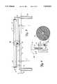
- FIG. 2is an end elevational view similar to FIG. 1 of the web material tensioning apparatus including the tension roller assembly and vacuum retraction assembly with the web cutting and tape application apparatus shown in greater detail.
- FIG. 3is a top elevational view of the tension roller assembly of the web material tensioning apparatus shown in FIG. 2.
- FIG. 4is a greatly enlarged end elevational view partially in section of a tensioning device circled in FIG. 3.
- FIG. 5is a front elevational view of the vacuum retraction assembly of the web material tensioning apparatus shown in FIG. 2.
- FIGS. 6-9are end elevational views illustrating the operation of the web material tensioning apparatus shown in FIG. 2.
- FIGS. 1 and 2A web material tensioning apparatus 10 in accordance with the present invention is illustrated generally in FIGS. 1 and 2.
- the tensioning apparatus 10includes a main frame 12 defined by a pair of spaced, upright front posts 14 and a pair of spaced, upright rear posts 16 (only one of which can be seen in FIG. 2).
- the front and rear posts 14 and 16are supported on a floor surface 18.
- Front posts 14are coupled together at their upper ends by a front cross member 20 while rear posts 16 are coupled together at their upper ends by a rear cross member 22.
- End cross members 24(only one of which can be seen in FIG. 2) couple upper ends of adjacent front and rear posts 14 and 16.
- An intermediate front connecting member 26, an intermediate rear connecting member 28 and end connecting members 29further join front and rear posts 14 and 16 and act to further rigidify main frame 12 (only one of which can be seen in FIG. 2).
- the main frame 12supports a movable carrier frame 30 defined by a front support member 32, a rear support member 34 and end support members 36 (forming a rigid structure as seen in FIG. 2).
- the carrier frame 30is linearly movable relative to the main frame 12 in opposite directions (as represented by double headed arrow 38 in FIGS. 1 and 2). via a main frame drive assembly 40.
- the drive assembly 40includes an electric drive motor 42 supported by the front cross member 20 of the main frame 12.
- a drive sprocket 44 on an output shaft of the drive motor 42is coupled to driven sprockets 46 of threaded drive rods 48 via a plurality of drive chains 50.
- Upper and lower ends of the threaded drive rods 48are supported for rotational movement within the front and rear posts 14 and 16 via upper and lower bearing elements 51 and 52, respectively.
- Threaded drive nuts 54 mounted on the carrier frame 30cooperate with the drive rods 48, such that upon operation of the drive motor 42 the drive rods 48 rotate in unison (via drive sprocket 44, drive chains 50, driven sprockets 46), thereby linearly driving the drive nuts 54 in the direction of double headed arrow 38 to raise and lower carrier frame 30 relative to main frame 12.
- the drive motor 42is coupled to an operator control panel 56 which houses a microprocessor 58 which controls the operation of the drive motor 42 and thereby the positioning of the carrier frame 30 relative to the main frame 12.
- the carrier frame 30supports a web material tensioning apparatus 60 defined by a tension roller assembly 62 and a vacuum retraction assembly 64.
- the carrier frame 30further supports a web cutting and tape application apparatus 66 that is linearly movable relative to the carrier frame 30 in opposite directions (as represented by double headed arrow 68 in FIG. 1).
- the carrier frame 30is movable relative to the main frame 12 so as to position the web material tensioning apparatus 60 and the web cutting and tape application apparatus 66 adjacent to a roll of web material 70 positioned within the confines of the main frame 12.
- the roll of web material 70is positioned within the confines of the main frame 12 such that an axis 71 of the roll of web material is parallel to the linear movement of the carrier frame 30 (as represented by double headed arrow 68) and in aligned registry with a tape application mechanism 72 of the web cutting and tape application apparatus 66.
- the tension roller assembly 62includes a channel member 74 supported for pivotable movement relative to end support members 36 of the carrier frame 30 via pivot pins 76.
- a pair of spaced linear drive elementssuch as pneumatic drive cylinders 78, having linearly movable drive pistons 80.
- the drive cylinders 78 aligned by dual guide shafts 79are configured to move the drive pistons in unison in opposite directions as represented by double headed arrow 81 in FIG. 3.
- the drive cylinders 78are coupled to a pneumatic pressure mechanism 82 on the pneumatic control panel 147 (see FIG. 7).
- the microprocessor 58controls the operation of the drive cylinders 78.
- the idler roller 84Upon operation of the drive cylinders 78, the idler roller 84 is linearly moved relative to the channel member 74.
- a rigid support bracket 86Further coupled between the drive pistons 80 is a rigid support bracket 86 that supports an idler roller tensioner 88 (sec FIG. 4).
- the idler roller tensioner 88includes a support member 89 mounted to the support bracket 86 via suitable fasteners 90.
- a lever arm 92is pivotably mounted to the support member 89 via pivot pins 93.
- a first end 94 of the lever arm 92is adapted to engage the idler roller 84 while a second end 96 of the lever arm 92 is engaged by a threaded rotatable screw element 98 mounted on the support bracket 86. Tightening of the screw element 98 in the direction of arrow 99 pivots the lever arm 92 in a first direction which applies pressure against the idler roller 84 thereby restricting to some degree the free rotation of the idler roller 84. Loosening of the screw element 98 in the direction of arrow 100 pivots the lever arm 92 in a second direction opposite to the first direction which reduces the pressure against the idler roller 84 thereby increasing to some degree the free rotation of the idler roller 84.
- the tension roller assembly 62further includes tension springs 102 mounted on the end support members 36 of the carrier frame 30 via support pins 103.
- a first end 104 of each tension spring 102bears against a bearing pin 105 on the end support member 36 while a second end 106 of each tension spring 102 bears against the channel member 74.
- the tension springs 102act to bias the tension roller assembly to the position shown in FIGS. 2 and 6.
- the vacuum retraction assembly 64includes a main channel structure 108 mounted on a slide element 111.
- the main channel structure 108is supported for linear movement (via slide elements 111 ) relative to and parallel to (as represented by double headed arrow 109 in FIG. 2) end support members 36 of the carrier frame 30.
- the slide elements 111located one per side in FIG. 5, are internally connected as part of main pneumatic rodless cylinders 110 that are mounted at all angle with respect to the carrier frame 30, with a first end 112 of each main cylinder 110 mounted to an end support member 146 and a second end 114 of each main cylinder 110 mounted to a raised end support member 116 (FIG. 2).
- the main rodless cylinders 110are configured to move the slide elements 111 in unison in opposite directions (as represented by double headed arrow 109 in FIG. 2) and to linearly move the channel structure 108 as best shown between FIGS. 6 and 7.
- the main rodless cylinders 110are coupled to the pneumatic pressure mechanism 82 on the pneumatic control panel 147.
- the microprocessor 58controls the operation of the main rodless cylinders 110.
- a pair of spaced linear drive elementssuch as secondary pneumatic drive cylinders 124, having linearly movable drive pistons 126.
- the secondary drive cylinders 124are configured to move the drive pistons 126 in unison in opposite directions as represented by double headed arrow 127 in FIG. 5.
- the secondary drive cylinders 124are coupled to the pneumatic pressure mechanism 82 mounted on the pneumatic control panel 147.
- the microprocessor 58controls the operation of the secondary drive cylinders 124.
- Coupled between ends of the drive pistons 126is a rotatable secondary channel element 128.
- the secondary channel element 128Upon operation of the secondary drive cylinders 124, the secondary channel element 128 is linearly moved relative to the main channel structure 108.
- the secondary channel element 128is rotatable relative to the drive pistons 126 via pneumatic rotary actuation device 129 supported by the drive pistons 126.
- Mounted on the secondary channel element 128are a pair of spaced linear drive elements, such as tertiary pneumatic drive cylinders 130, having linearly movable drive pistons 132.
- the tertiary drive cylinders 130are configured to move the drive pistons 132 in unison in opposite directions as represented by double headed arrow 133 in FIG. 5.
- the tertiary drive cylinders 130are coupled to the pneumatic pressure mechanism 82 mounted on the pneumatic control panel 147 (see FIG. 7).
- the microprocessor 58controls the operation of the tertiary
- the vacuum bar 136Coupled between ends of the drive pistons 132 is a vacuum bar 136 that is rotatable with the secondary channel element 128. Upon operation of the tertiary drive cylinders 130, the vacuum bar 136 is linearly moved relative to the secondary channel element 128 in the direction of double headed arrow 133.
- the vacuum bar 136includes a plurality of spaced vacuum cups 140 which are coupled to a vacuum source 142 via a vacuum channel 144 in the vacuum bar 136 (see FIG. 8).
- the carrier frame 30is lowered via operation of the drive motor 42 so as to position the web material tensioning apparatus 60 and the web cutting and tape application apparatus 66 immediately adjacent the web material of the roll of web material 70 (see FIG. 6).
- the drive cylinders 78 of the tension roller assembly 62are then actuated to extend the drive pistons 80 such that the idler roller 84 engages the web material of the roll of web material 70.
- the main rodless cylinders 110are actuated moving the slide elements 111 and the vacuum retraction channel structure 108 down to the lower travel limit at the first ends 112 of the main rodless cylinders 110 (see FIG. 7).
- the vacuum source 142is activated and then the rotary actuation device 129 is actuated rotating the vacuum bar 136 to the position shown in FIG. 8 with the vacuum cups 140 extending generally perpendicular to a tangent of the roll of web material 70.
- the tertiary drive cylinders 130are actuated extending the drive pistons 132 such that the vacuum cups 140 contact the outer layer of web material of the roll of web material 70.
- the vacuum pressure through the vacuum cups 140causes the outer layer of web material 150 to adhere to the vacuum bar 136.
- the drive pistons 132are retracted, the secondary channel element 128 is rotated back and the drive pistons 126 are retracted to return all the vacuum bar 136 back to its home position.
- the slide elements 111are partially retracted to move the main channel structure 108 back along the main rodless cylinders 110 acting to further tension the outer layer 150 of the roll of web material 70.
- the web cutting and tape application apparatusis actuated to form a cut leading edge of web material.
- the drive pistons 122 and 78are fully retracted and the drive motor 42 is reversed, thereby returning all elements to their home position illustrated in FIG. 6.
- the inventive web tensioning apparatus 10 disclosed hereinprovides an automated means for tensioning an outer layer 150 of a roll of web material 70 to substantially eliminate web material slack and wrinkles to permit the accurate formation of a cut leading edge of web material of desired shape and consistency from one cut to the next. This allows splicing tape to be applied to the cut leading edge of web material quickly and with alignment accuracy.
Landscapes
- Controlling Rewinding, Feeding, Winding, Or Abnormalities Of Webs (AREA)
Abstract
Description
Claims (17)
Priority Applications (1)
| Application Number | Priority Date | Filing Date | Title |
|---|---|---|---|
| US08/146,888US5524844A (en) | 1993-10-29 | 1993-10-29 | Apparatus for preparing a leading edge of web material |
Applications Claiming Priority (1)
| Application Number | Priority Date | Filing Date | Title |
|---|---|---|---|
| US08/146,888US5524844A (en) | 1993-10-29 | 1993-10-29 | Apparatus for preparing a leading edge of web material |
Publications (1)
| Publication Number | Publication Date |
|---|---|
| US5524844Atrue US5524844A (en) | 1996-06-11 |
Family
ID=22519432
Family Applications (1)
| Application Number | Title | Priority Date | Filing Date |
|---|---|---|---|
| US08/146,888Expired - LifetimeUS5524844A (en) | 1993-10-29 | 1993-10-29 | Apparatus for preparing a leading edge of web material |
Country Status (1)
| Country | Link |
|---|---|
| US (1) | US5524844A (en) |
Cited By (9)
| Publication number | Priority date | Publication date | Assignee | Title |
|---|---|---|---|---|
| US20010007503A1 (en)* | 2000-01-12 | 2001-07-12 | Katsuya Inana | Printer for use with rolled recording paper |
| US20020189746A1 (en)* | 2001-06-15 | 2002-12-19 | Kuta Leroy A. | Method and apparatus for automatically applying a flying splicing tape to a roll of sheet material |
| US20030116256A1 (en)* | 2001-12-21 | 2003-06-26 | 3M Innovative Properties Company | Method and apparatus for applying a splicing tape to a roll of sheet material |
| US6688205B1 (en)* | 1998-02-10 | 2004-02-10 | Du Pont Teijin Films Uk, Ltd. | High speed cutting assembly |
| EP1422174A1 (en)* | 2002-10-14 | 2004-05-26 | Metso Paper AG | Method and device for the preparation of a stockage paper web for the flying roll exchange |
| US20050011986A1 (en)* | 2003-07-18 | 2005-01-20 | Semiconductor Components Industries, Llc. | Semiconductor assembly method and equipment therefor |
| US6951676B2 (en) | 2000-09-25 | 2005-10-04 | 3M Innovative Properties Company | Butt splicing tapes and butt splicing methods |
| US20220106143A1 (en)* | 2019-06-20 | 2022-04-07 | Jiangsu Katop Automation Co., Ltd | Multifunctional apparatus and method of automatic punching, laminating, tape-preparing and cutting for tailing ends of coiled materials |
| US20240299999A1 (en)* | 2021-01-07 | 2024-09-12 | Danieli & C. Officine Meccaniche S.P.A. | Device and method for unwinding and inspection of metallic strip coils |
Citations (29)
| Publication number | Priority date | Publication date | Assignee | Title |
|---|---|---|---|---|
| US2346756A (en)* | 1942-01-10 | 1944-04-18 | Nat Bread Wrapping Machine Co | Paper reel brake |
| US2880778A (en)* | 1956-09-13 | 1959-04-07 | United States Steel Corp | Apparatus for pulling the end from a coil of strip |
| US3010672A (en)* | 1959-09-01 | 1961-11-28 | Jr Owen S Cecil | Coil opener and uncoiler |
| US3066723A (en)* | 1961-08-21 | 1962-12-04 | Peerless Tube Company | Machine for applying label tear strips to containers |
| US3315592A (en)* | 1965-10-14 | 1967-04-25 | Signode Corp | Method of and apparatus for tightening and strapping involutely wound sheet metal coils |
| US3329083A (en)* | 1965-09-13 | 1967-07-04 | Bellmann Friedhelm | Method and apparatus for tightening and banding metal coils |
| US3406084A (en)* | 1966-11-02 | 1968-10-15 | Stapling Machines Co | Tape applicator |
| US3417688A (en)* | 1966-07-13 | 1968-12-24 | Stanley Works | Coil-tightening apparatus |
| US3602448A (en)* | 1970-02-03 | 1971-08-31 | Alcan Res & Dev | Web-winding apparatus |
| US3630346A (en)* | 1970-06-01 | 1971-12-28 | Lilly Co Eli | Components for making a strip package |
| US3765992A (en)* | 1971-12-30 | 1973-10-16 | Minnesota Mining & Mfg | Strip adhesive application mechanism |
| US3834204A (en)* | 1972-06-10 | 1974-09-10 | Ungerer Irma | Machine for wrap forming metal strip as it is uncoiled |
| US3899142A (en)* | 1973-08-27 | 1975-08-12 | Sonoco Products Co | Roll tightener |
| US4177959A (en)* | 1978-10-02 | 1979-12-11 | Lancaster Patrick R | Flying splice apparatus and process |
| GB2025376A (en)* | 1978-07-12 | 1980-01-23 | Bonnierfoeretagen Ab | An arrangement in newspaper printing presses |
| US4351687A (en)* | 1980-04-16 | 1982-09-28 | Gaston Lesage | Machine for coiling strip material with a device for momentary immobilization of the tails of the strips |
| US4398379A (en)* | 1981-03-11 | 1983-08-16 | Burford Charles E | Tab attachment device |
| US4459170A (en)* | 1980-07-08 | 1984-07-10 | The Meyercord Co. | Method and apparatus for applying decals to articles |
| US4555288A (en)* | 1983-06-20 | 1985-11-26 | Dai Nippon Insatsu Kabushiki Kaisha | Method of and device for preparing paper rolls for rotary presses and the like |
| US4636276A (en)* | 1983-06-20 | 1987-01-13 | Dai Nippon Insatsu Kabushiki Kaisha | Automatic adhesive double coated tape applying device |
| US4840320A (en)* | 1986-12-25 | 1989-06-20 | Japan Tobacco Inc. | Apparatus for automatically threading the leading edge of a spooled web into a conveying passage |
| US4861411A (en)* | 1988-01-20 | 1989-08-29 | Fuji Photo Film Co., Ltd. | Method of producing gel sheet for electrophoresis |
| US4905924A (en)* | 1989-07-10 | 1990-03-06 | Enkel Corporation | Web splicing tape |
| US4980011A (en)* | 1988-01-27 | 1990-12-25 | Minnesota Mining And Manufacturing Company | Automated liner removing transfer tape applicator |
| US4995406A (en)* | 1988-02-25 | 1991-02-26 | Fabriques De Tabac Reunies, S.A. | Apparatus and method for opening a reel of paper stripping |
| CA2025473A1 (en)* | 1989-09-19 | 1991-03-20 | Josef Hammer | Method of pre-treating a renewal web rolled on a roll for adhesion to a previously used web, particularly paper web for use in printing machines, and renewal web adhesion system |
| US5076878A (en)* | 1990-03-02 | 1991-12-31 | Minnesota Mining And Manufacturing Company | Device for applying adhesive to elongate members |
| CA2069247A1 (en)* | 1991-06-07 | 1992-12-08 | Norbert Dylla | Method and Apparatus of Preparing a Roll of Printing Substrate Web for Flying Pasting |
| US5212002A (en)* | 1990-04-03 | 1993-05-18 | J. M. Voith Gmbh | Splice and process for making a splice on the leader of a paper roll |
- 1993
- 1993-10-29USUS08/146,888patent/US5524844A/ennot_activeExpired - Lifetime
Patent Citations (30)
| Publication number | Priority date | Publication date | Assignee | Title |
|---|---|---|---|---|
| US2346756A (en)* | 1942-01-10 | 1944-04-18 | Nat Bread Wrapping Machine Co | Paper reel brake |
| US2880778A (en)* | 1956-09-13 | 1959-04-07 | United States Steel Corp | Apparatus for pulling the end from a coil of strip |
| US3010672A (en)* | 1959-09-01 | 1961-11-28 | Jr Owen S Cecil | Coil opener and uncoiler |
| US3066723A (en)* | 1961-08-21 | 1962-12-04 | Peerless Tube Company | Machine for applying label tear strips to containers |
| US3329083A (en)* | 1965-09-13 | 1967-07-04 | Bellmann Friedhelm | Method and apparatus for tightening and banding metal coils |
| US3315592A (en)* | 1965-10-14 | 1967-04-25 | Signode Corp | Method of and apparatus for tightening and strapping involutely wound sheet metal coils |
| US3417688A (en)* | 1966-07-13 | 1968-12-24 | Stanley Works | Coil-tightening apparatus |
| US3406084A (en)* | 1966-11-02 | 1968-10-15 | Stapling Machines Co | Tape applicator |
| US3602448A (en)* | 1970-02-03 | 1971-08-31 | Alcan Res & Dev | Web-winding apparatus |
| US3630346A (en)* | 1970-06-01 | 1971-12-28 | Lilly Co Eli | Components for making a strip package |
| US3765992A (en)* | 1971-12-30 | 1973-10-16 | Minnesota Mining & Mfg | Strip adhesive application mechanism |
| US3834204A (en)* | 1972-06-10 | 1974-09-10 | Ungerer Irma | Machine for wrap forming metal strip as it is uncoiled |
| US3899142A (en)* | 1973-08-27 | 1975-08-12 | Sonoco Products Co | Roll tightener |
| GB2025376A (en)* | 1978-07-12 | 1980-01-23 | Bonnierfoeretagen Ab | An arrangement in newspaper printing presses |
| US4177959A (en)* | 1978-10-02 | 1979-12-11 | Lancaster Patrick R | Flying splice apparatus and process |
| US4351687A (en)* | 1980-04-16 | 1982-09-28 | Gaston Lesage | Machine for coiling strip material with a device for momentary immobilization of the tails of the strips |
| US4459170A (en)* | 1980-07-08 | 1984-07-10 | The Meyercord Co. | Method and apparatus for applying decals to articles |
| US4398379A (en)* | 1981-03-11 | 1983-08-16 | Burford Charles E | Tab attachment device |
| US4555288A (en)* | 1983-06-20 | 1985-11-26 | Dai Nippon Insatsu Kabushiki Kaisha | Method of and device for preparing paper rolls for rotary presses and the like |
| US4597820A (en)* | 1983-06-20 | 1986-07-01 | Dai Nippon Insatsu Kabushiki Kaisha | Method of and device for preparing paper rolls for rotary presses and the like |
| US4636276A (en)* | 1983-06-20 | 1987-01-13 | Dai Nippon Insatsu Kabushiki Kaisha | Automatic adhesive double coated tape applying device |
| US4840320A (en)* | 1986-12-25 | 1989-06-20 | Japan Tobacco Inc. | Apparatus for automatically threading the leading edge of a spooled web into a conveying passage |
| US4861411A (en)* | 1988-01-20 | 1989-08-29 | Fuji Photo Film Co., Ltd. | Method of producing gel sheet for electrophoresis |
| US4980011A (en)* | 1988-01-27 | 1990-12-25 | Minnesota Mining And Manufacturing Company | Automated liner removing transfer tape applicator |
| US4995406A (en)* | 1988-02-25 | 1991-02-26 | Fabriques De Tabac Reunies, S.A. | Apparatus and method for opening a reel of paper stripping |
| US4905924A (en)* | 1989-07-10 | 1990-03-06 | Enkel Corporation | Web splicing tape |
| CA2025473A1 (en)* | 1989-09-19 | 1991-03-20 | Josef Hammer | Method of pre-treating a renewal web rolled on a roll for adhesion to a previously used web, particularly paper web for use in printing machines, and renewal web adhesion system |
| US5076878A (en)* | 1990-03-02 | 1991-12-31 | Minnesota Mining And Manufacturing Company | Device for applying adhesive to elongate members |
| US5212002A (en)* | 1990-04-03 | 1993-05-18 | J. M. Voith Gmbh | Splice and process for making a splice on the leader of a paper roll |
| CA2069247A1 (en)* | 1991-06-07 | 1992-12-08 | Norbert Dylla | Method and Apparatus of Preparing a Roll of Printing Substrate Web for Flying Pasting |
Cited By (16)
| Publication number | Priority date | Publication date | Assignee | Title |
|---|---|---|---|---|
| US6688205B1 (en)* | 1998-02-10 | 2004-02-10 | Du Pont Teijin Films Uk, Ltd. | High speed cutting assembly |
| US20010007503A1 (en)* | 2000-01-12 | 2001-07-12 | Katsuya Inana | Printer for use with rolled recording paper |
| US6914688B2 (en)* | 2000-01-12 | 2005-07-05 | Fuji Photo Film Co., Ltd. | Printer for use with rolled recording paper |
| US6951676B2 (en) | 2000-09-25 | 2005-10-04 | 3M Innovative Properties Company | Butt splicing tapes and butt splicing methods |
| US6808581B2 (en) | 2001-06-15 | 2004-10-26 | 3M Innovative Properties Company | Method and apparatus for automatically applying a flying splicing tape to a roll of sheet material |
| US20020189746A1 (en)* | 2001-06-15 | 2002-12-19 | Kuta Leroy A. | Method and apparatus for automatically applying a flying splicing tape to a roll of sheet material |
| WO2003057605A1 (en)* | 2001-12-21 | 2003-07-17 | 3M Innovative Properties Company | Method and apparatus for applying a splicing tape to a roll of sheet material |
| US6814123B2 (en)* | 2001-12-21 | 2004-11-09 | 3M Innovative Properties Company | Method and apparatus for applying a splicing tape to a roll of sheet material |
| US20030116256A1 (en)* | 2001-12-21 | 2003-06-26 | 3M Innovative Properties Company | Method and apparatus for applying a splicing tape to a roll of sheet material |
| EP1422174A1 (en)* | 2002-10-14 | 2004-05-26 | Metso Paper AG | Method and device for the preparation of a stockage paper web for the flying roll exchange |
| US6805765B1 (en) | 2002-10-14 | 2004-10-19 | Metso Paper Ag | Method and apparatus for the preparation of a paper reel for flying reel change |
| US20050011986A1 (en)* | 2003-07-18 | 2005-01-20 | Semiconductor Components Industries, Llc. | Semiconductor assembly method and equipment therefor |
| US6892976B2 (en)* | 2003-07-18 | 2005-05-17 | Semiconductor Components Industries, L.L.C. | Semiconductor assembly method and equipment therefor |
| US20220106143A1 (en)* | 2019-06-20 | 2022-04-07 | Jiangsu Katop Automation Co., Ltd | Multifunctional apparatus and method of automatic punching, laminating, tape-preparing and cutting for tailing ends of coiled materials |
| US12151910B2 (en)* | 2019-06-20 | 2024-11-26 | Jiangsu Katop Automation Co., Ltd | Multifunctional apparatus and method of automatic punching, laminating, tape-preparing and cutting for tailing ends of coiled materials |
| US20240299999A1 (en)* | 2021-01-07 | 2024-09-12 | Danieli & C. Officine Meccaniche S.P.A. | Device and method for unwinding and inspection of metallic strip coils |
Similar Documents
| Publication | Publication Date | Title |
|---|---|---|
| US5431767A (en) | Apparatus for applying adhesive tape | |
| US5658420A (en) | Apparatus for applying adhesive tape | |
| JP2545557B2 (en) | Winding paper end treatment method and device | |
| US4170506A (en) | Method of web splicing | |
| EP0101044A1 (en) | Method and apparatus for splicing successive web rolls to feed a web into a rotary press or the like | |
| EP0427408A2 (en) | Continuous winder for web materials | |
| GB2125774A (en) | Web splicing apparatus | |
| US7533844B2 (en) | Paper splicing apparatus | |
| GB2123801A (en) | Improvments in or relating to splicing webs | |
| JP2659033B2 (en) | Device to connect the ends of the packaging web | |
| US5524844A (en) | Apparatus for preparing a leading edge of web material | |
| GB1569886A (en) | Splicing webs of sheet material | |
| CA1227963A (en) | Pads and their formation | |
| MXPA02002177A (en) | Apparatus and a method for rolling compressible sheet material. | |
| US5171396A (en) | Device for splicing paper webs for the production of corrugated board | |
| CN212174037U (en) | Double-station splitting machine | |
| GB2129406A (en) | Splicing webs | |
| EP0372757A2 (en) | Web-aligning apparatus | |
| CA1180260A (en) | Web splicing apparatus | |
| US5256232A (en) | Apparatus and method for winding strips of web material onto spools | |
| CN210619661U (en) | Non-stop positioning and splicing paper adjusting and positioning device | |
| CN113023434B (en) | Non-stop printing device | |
| US7114675B1 (en) | Dual-drum winding machine | |
| US5524804A (en) | Lock-out device for threading in a strip guide apparatus | |
| CN110576673B (en) | Satellite type full-rotary printing machine capable of quickly receiving paper |
Legal Events
| Date | Code | Title | Description |
|---|---|---|---|
| AS | Assignment | Owner name:ENKEL CORPORATION, ILLINOIS Free format text:ASSIGNMENT OF ASSIGNORS INTEREST;ASSIGNORS:MCCORMICK, MICHAEL O.;MOORE, CHESTER W.;HICKS, DANIEL R.;AND OTHERS;REEL/FRAME:006870/0763 Effective date:19931227 | |
| STCF | Information on status: patent grant | Free format text:PATENTED CASE | |
| CC | Certificate of correction | ||
| FEPP | Fee payment procedure | Free format text:PAYOR NUMBER ASSIGNED (ORIGINAL EVENT CODE: ASPN); ENTITY STATUS OF PATENT OWNER: LARGE ENTITY | |
| FEPP | Fee payment procedure | Free format text:PAT HOLDER CLAIMS SMALL ENTITY STATUS - SMALL BUSINESS (ORIGINAL EVENT CODE: SM02); ENTITY STATUS OF PATENT OWNER: LARGE ENTITY | |
| FPAY | Fee payment | Year of fee payment:4 | |
| AS | Assignment | Owner name:FLEET NATIONAL BANK, CONNECTICUT Free format text:SECURITY INTEREST;ASSIGNOR:BALDWIN ENKEL CORPORATION (A DELAWARE CORPORATION);REEL/FRAME:012124/0609 Effective date:20001031 | |
| AS | Assignment | Owner name:BALDWIN ENKEL CORPORATION, CONNECTICUT Free format text:RELEASE OF SECURITY INTEREST;ASSIGNOR:FLEET NATIONAL BANK;REEL/FRAME:012243/0172 Effective date:20010924 | |
| AS | Assignment | Owner name:MEGTEC SYSTEMS, INC., WISCONSIN Free format text:ASSIGNMENT OF ASSIGNORS INTEREST;ASSIGNOR:BALDWIN ENKEL CORPORATION;REEL/FRAME:012252/0148 Effective date:20010926 | |
| FEPP | Fee payment procedure | Free format text:PAT HOLDER NO LONGER CLAIMS SMALL ENTITY STATUS, ENTITY STATUS SET TO UNDISCOUNTED (ORIGINAL EVENT CODE: STOL); ENTITY STATUS OF PATENT OWNER: LARGE ENTITY | |
| REFU | Refund | Free format text:REFUND - PAYMENT OF MAINTENANCE FEE, 8TH YR, SMALL ENTITY (ORIGINAL EVENT CODE: R2552); ENTITY STATUS OF PATENT OWNER: LARGE ENTITY | |
| FPAY | Fee payment | Year of fee payment:8 | |
| FPAY | Fee payment | Year of fee payment:12 | |
| AS | Assignment | Owner name:LEHMAN COMMERCIAL PAPER, INC., NEW YORK Free format text:GUARANTEE AND COLLATERAL AGREEMENT;ASSIGNOR:MEGTEC SYSTEMS, INC.;REEL/FRAME:020525/0827 Effective date:20071203 | |
| AS | Assignment | Owner name:SEQUA GMBH & CO., WISCONSIN Free format text:RELEASED BY SECURED PARTY;ASSIGNOR:LEHMAN COMMERCIAL PAPER, INC.;REEL/FRAME:021630/0602 Effective date:20080924 Owner name:MEGTEC SYSTEMS AB, WISCONSIN Free format text:RELEASED BY SECURED PARTY;ASSIGNOR:LEHMAN COMMERCIAL PAPER, INC.;REEL/FRAME:021630/0602 Effective date:20080924 Owner name:MEGTEC SYSTEMS, INC., WISCONSIN Free format text:RELEASED BY SECURED PARTY;ASSIGNOR:LEHMAN COMMERCIAL PAPER, INC.;REEL/FRAME:021630/0602 Effective date:20080924 Owner name:MEGTEC SYSTEMS AUSTRALIA, INC., WISCONSIN Free format text:RELEASED BY SECURED PARTY;ASSIGNOR:LEHMAN COMMERCIAL PAPER, INC.;REEL/FRAME:021630/0602 Effective date:20080924 Owner name:MTS ASIA, INC., WISCONSIN Free format text:RELEASED BY SECURED PARTY;ASSIGNOR:LEHMAN COMMERCIAL PAPER, INC.;REEL/FRAME:021630/0602 Effective date:20080924 Owner name:MEGTEC SYSTEMS AMAL AB, WISCONSIN Free format text:RELEASED BY SECURED PARTY;ASSIGNOR:LEHMAN COMMERCIAL PAPER, INC.;REEL/FRAME:021630/0602 Effective date:20080924 Owner name:MEGTEC SYSTEMS KG, WISCONSIN Free format text:RELEASED BY SECURED PARTY;ASSIGNOR:LEHMAN COMMERCIAL PAPER, INC.;REEL/FRAME:021630/0602 Effective date:20080924 Owner name:MEGTEC SYSTEMS, S.A.S., WISCONSIN Free format text:RELEASED BY SECURED PARTY;ASSIGNOR:LEHMAN COMMERCIAL PAPER, INC.;REEL/FRAME:021630/0602 Effective date:20080924 | |
| AS | Assignment | Owner name:MEGTEC SYSTEMS, INC., WISCONSIN Free format text:TERMINATION OF SECURITY INTEREST IN PATENTS AT REEL/FRAME NOS. 20525/0827 AND 20571/0001;ASSIGNOR:LEHMAN COMMERCIAL PAPER, INC.;REEL/FRAME:021617/0548 Effective date:20080924 | |
| AS | Assignment | Owner name:BANK OF AMERICA, N.A., AS ADMINISTRATIVE AGENT, NO Free format text:SECURITY AGREEMENT;ASSIGNOR:MEGTEC SYSTEMS, INC.;REEL/FRAME:021719/0141 Effective date:20080924 | |
| AS | Assignment | Owner name:TD BANK, N.A., AS ADMINISTRATIVE AGENT, CONNECTICU Free format text:PATENT COLLATERAL ASSIGNMENT AND SECURITY AGREEMENT;ASSIGNOR:MEGTEC SYSTEMS, INC.;REEL/FRAME:027396/0140 Effective date:20111216 | |
| AS | Assignment | Owner name:MEGTEC SYSTEMS, INC., WISCONSIN Free format text:TERMINATION AND RELEASE OF SECURITY INTEREST IN PATENT AND TRADEMARK RIGHTS;ASSIGNOR:BANK OF AMERICA, N.A., AS ADMINISTRATIVE AGENT;REEL/FRAME:027430/0112 Effective date:20111216 |