US5524636A - Method and apparatus for elasticity imaging - Google Patents
Method and apparatus for elasticity imagingDownload PDFInfo
- Publication number
- US5524636A US5524636AUS07/994,109US99410992AUS5524636AUS 5524636 AUS5524636 AUS 5524636AUS 99410992 AUS99410992 AUS 99410992AUS 5524636 AUS5524636 AUS 5524636A
- Authority
- US
- United States
- Prior art keywords
- tissue
- pressure
- strain
- tissue portion
- elasticity
- Prior art date
- Legal status (The legal status is an assumption and is not a legal conclusion. Google has not performed a legal analysis and makes no representation as to the accuracy of the status listed.)
- Expired - Lifetime
Links
- 238000000034methodMethods0.000titleclaimsabstractdescription85
- 238000003384imaging methodMethods0.000titleclaimsabstractdescription59
- 238000009826distributionMethods0.000claimsabstractdescription9
- 210000001519tissueAnatomy0.000claimsdescription565
- 239000002245particleSubstances0.000claimsdescription74
- 230000006835compressionEffects0.000claimsdescription46
- 238000007906compressionMethods0.000claimsdescription46
- 239000000523sampleSubstances0.000claimsdescription45
- 238000006073displacement reactionMethods0.000claimsdescription34
- 238000011068loading methodMethods0.000claimsdescription33
- 230000000694effectsEffects0.000claimsdescription17
- 230000033001locomotionEffects0.000claimsdescription16
- 238000005259measurementMethods0.000claimsdescription12
- 238000002595magnetic resonance imagingMethods0.000claimsdescription11
- 239000012530fluidSubstances0.000claimsdescription10
- 210000003205muscleAnatomy0.000claimsdescription8
- 210000004204blood vesselAnatomy0.000claimsdescription7
- 210000000038chestAnatomy0.000claimsdescription7
- 230000000712assemblyEffects0.000claims2
- 238000000429assemblyMethods0.000claims2
- 238000003825pressingMethods0.000claims1
- 206010028980NeoplasmDiseases0.000description189
- 230000008859changeEffects0.000description37
- 230000035945sensitivityEffects0.000description24
- 238000004458analytical methodMethods0.000description22
- 210000003491skinAnatomy0.000description17
- 238000002604ultrasonographyMethods0.000description16
- 230000036772blood pressureEffects0.000description14
- 238000001514detection methodMethods0.000description13
- 230000000875corresponding effectEffects0.000description12
- 210000003414extremityAnatomy0.000description9
- 210000004872soft tissueAnatomy0.000description9
- 239000013598vectorSubstances0.000description9
- 238000011156evaluationMethods0.000description8
- 210000000481breastAnatomy0.000description7
- 238000002559palpationMethods0.000description7
- 238000013459approachMethods0.000description6
- 230000007423decreaseEffects0.000description6
- 238000010586diagramMethods0.000description6
- 230000004044responseEffects0.000description6
- 230000005856abnormalityEffects0.000description5
- 238000003491arrayMethods0.000description5
- 230000010351cardiac pulsationEffects0.000description5
- 238000006243chemical reactionMethods0.000description5
- 230000002123temporal effectEffects0.000description5
- 230000007704transitionEffects0.000description5
- 238000004364calculation methodMethods0.000description4
- 230000003902lesionEffects0.000description4
- 239000000463materialSubstances0.000description4
- 238000012986modificationMethods0.000description4
- 230000004048modificationEffects0.000description4
- 208000026310Breast neoplasmDiseases0.000description3
- 210000000988bone and boneAnatomy0.000description3
- 230000001276controlling effectEffects0.000description3
- 210000002615epidermisAnatomy0.000description3
- 238000012544monitoring processMethods0.000description3
- 210000000664rectumAnatomy0.000description3
- 210000000707wristAnatomy0.000description3
- 229910000831SteelInorganic materials0.000description2
- 210000003484anatomyAnatomy0.000description2
- 230000015572biosynthetic processEffects0.000description2
- 239000008280bloodSubstances0.000description2
- 210000004369bloodAnatomy0.000description2
- 201000011510cancerDiseases0.000description2
- 230000008602contractionEffects0.000description2
- 230000008878couplingEffects0.000description2
- 238000010168coupling processMethods0.000description2
- 238000005859coupling reactionMethods0.000description2
- 230000001351cycling effectEffects0.000description2
- 238000013461designMethods0.000description2
- 210000000245forearmAnatomy0.000description2
- 238000005755formation reactionMethods0.000description2
- 238000001727in vivoMethods0.000description2
- 230000001788irregularEffects0.000description2
- 230000035515penetrationEffects0.000description2
- 208000023958prostate neoplasmDiseases0.000description2
- 238000004445quantitative analysisMethods0.000description2
- 230000005855radiationEffects0.000description2
- 238000007789sealingMethods0.000description2
- 238000004088simulationMethods0.000description2
- 239000010959steelSubstances0.000description2
- 238000003325tomographyMethods0.000description2
- XLYOFNOQVPJJNP-UHFFFAOYSA-NwaterSubstancesOXLYOFNOQVPJJNP-UHFFFAOYSA-N0.000description2
- 206010006187Breast cancerDiseases0.000description1
- 206010035148PlagueDiseases0.000description1
- 239000004952PolyamideSubstances0.000description1
- 241001632427RadiolaSpecies0.000description1
- 241000607479Yersinia pestisSpecies0.000description1
- 230000009471actionEffects0.000description1
- 230000003321amplificationEffects0.000description1
- 210000002376aorta thoracicAnatomy0.000description1
- 230000008901benefitEffects0.000description1
- 239000003795chemical substances by applicationSubstances0.000description1
- 210000001072colonAnatomy0.000description1
- 150000001875compoundsChemical class0.000description1
- 238000002591computed tomographyMethods0.000description1
- 230000003750conditioning effectEffects0.000description1
- 210000002808connective tissueAnatomy0.000description1
- 238000010276constructionMethods0.000description1
- 238000007796conventional methodMethods0.000description1
- 230000002596correlated effectEffects0.000description1
- 230000003247decreasing effectEffects0.000description1
- 230000002950deficientEffects0.000description1
- 238000011161developmentMethods0.000description1
- 230000004069differentiationEffects0.000description1
- 230000005489elastic deformationEffects0.000description1
- 239000013013elastic materialSubstances0.000description1
- 238000002091elastographyMethods0.000description1
- 230000000762glandularEffects0.000description1
- 238000010191image analysisMethods0.000description1
- 230000006872improvementEffects0.000description1
- 238000003780insertionMethods0.000description1
- 230000037431insertionEffects0.000description1
- 230000009545invasionEffects0.000description1
- 239000007788liquidSubstances0.000description1
- 238000009607mammographyMethods0.000description1
- 239000011159matrix materialSubstances0.000description1
- 230000004118muscle contractionEffects0.000description1
- 230000002107myocardial effectEffects0.000description1
- 238000013421nuclear magnetic resonance imagingMethods0.000description1
- 238000003199nucleic acid amplification methodMethods0.000description1
- 230000010355oscillationEffects0.000description1
- 230000007170pathologyEffects0.000description1
- 230000002093peripheral effectEffects0.000description1
- 235000019271petrolatumNutrition0.000description1
- 230000006461physiological responseEffects0.000description1
- 239000004033plasticSubstances0.000description1
- 229920002647polyamidePolymers0.000description1
- 239000002243precursorSubstances0.000description1
- 238000012545processingMethods0.000description1
- 238000011158quantitative evaluationMethods0.000description1
- 230000001105regulatory effectEffects0.000description1
- 230000000717retained effectEffects0.000description1
- 238000005096rolling processMethods0.000description1
- 230000037390scarringEffects0.000description1
- 239000000565sealantSubstances0.000description1
- 238000000926separation methodMethods0.000description1
- 239000007787solidSubstances0.000description1
- 230000009466transformationEffects0.000description1
- 238000012285ultrasound imagingMethods0.000description1
- 230000002861ventricularEffects0.000description1
- 239000003190viscoelastic substanceSubstances0.000description1
Images


Classifications
- A—HUMAN NECESSITIES
- A61—MEDICAL OR VETERINARY SCIENCE; HYGIENE
- A61B—DIAGNOSIS; SURGERY; IDENTIFICATION
- A61B5/00—Measuring for diagnostic purposes; Identification of persons
- A61B5/43—Detecting, measuring or recording for evaluating the reproductive systems
- A61B5/4306—Detecting, measuring or recording for evaluating the reproductive systems for evaluating the female reproductive systems, e.g. gynaecological evaluations
- A61B5/4312—Breast evaluation or disorder diagnosis
- A—HUMAN NECESSITIES
- A61—MEDICAL OR VETERINARY SCIENCE; HYGIENE
- A61B—DIAGNOSIS; SURGERY; IDENTIFICATION
- A61B1/00—Instruments for performing medical examinations of the interior of cavities or tubes of the body by visual or photographical inspection, e.g. endoscopes; Illuminating arrangements therefor
- A61B1/005—Flexible endoscopes
- A61B1/0051—Flexible endoscopes with controlled bending of insertion part
- A61B1/0052—Constructional details of control elements, e.g. handles
- A—HUMAN NECESSITIES
- A61—MEDICAL OR VETERINARY SCIENCE; HYGIENE
- A61B—DIAGNOSIS; SURGERY; IDENTIFICATION
- A61B5/00—Measuring for diagnostic purposes; Identification of persons
- A61B5/0048—Detecting, measuring or recording by applying mechanical forces or stimuli
- A61B5/0053—Detecting, measuring or recording by applying mechanical forces or stimuli by applying pressure, e.g. compression, indentation, palpation, grasping, gauging
- A—HUMAN NECESSITIES
- A61—MEDICAL OR VETERINARY SCIENCE; HYGIENE
- A61B—DIAGNOSIS; SURGERY; IDENTIFICATION
- A61B5/00—Measuring for diagnostic purposes; Identification of persons
- A61B5/03—Measuring fluid pressure within the body other than blood pressure, e.g. cerebral pressure ; Measuring pressure in body tissues or organs
- A61B5/036—Measuring fluid pressure within the body other than blood pressure, e.g. cerebral pressure ; Measuring pressure in body tissues or organs by means introduced into body tracts
- A—HUMAN NECESSITIES
- A61—MEDICAL OR VETERINARY SCIENCE; HYGIENE
- A61B—DIAGNOSIS; SURGERY; IDENTIFICATION
- A61B5/00—Measuring for diagnostic purposes; Identification of persons
- A61B5/06—Devices, other than using radiation, for detecting or locating foreign bodies ; Determining position of diagnostic devices within or on the body of the patient
- A61B5/061—Determining position of a probe within the body employing means separate from the probe, e.g. sensing internal probe position employing impedance electrodes on the surface of the body
- A61B5/064—Determining position of a probe within the body employing means separate from the probe, e.g. sensing internal probe position employing impedance electrodes on the surface of the body using markers
- A—HUMAN NECESSITIES
- A61—MEDICAL OR VETERINARY SCIENCE; HYGIENE
- A61B—DIAGNOSIS; SURGERY; IDENTIFICATION
- A61B8/00—Diagnosis using ultrasonic, sonic or infrasonic waves
- A61B8/08—Clinical applications
- A61B8/0825—Clinical applications for diagnosis of the breast, e.g. mammography
- A—HUMAN NECESSITIES
- A61—MEDICAL OR VETERINARY SCIENCE; HYGIENE
- A61B—DIAGNOSIS; SURGERY; IDENTIFICATION
- A61B8/00—Diagnosis using ultrasonic, sonic or infrasonic waves
- A61B8/08—Clinical applications
- A61B8/0833—Clinical applications involving detecting or locating foreign bodies or organic structures
- A—HUMAN NECESSITIES
- A61—MEDICAL OR VETERINARY SCIENCE; HYGIENE
- A61B—DIAGNOSIS; SURGERY; IDENTIFICATION
- A61B8/00—Diagnosis using ultrasonic, sonic or infrasonic waves
- A61B8/48—Diagnostic techniques
- A61B8/485—Diagnostic techniques involving measuring strain or elastic properties
- G—PHYSICS
- G01—MEASURING; TESTING
- G01S—RADIO DIRECTION-FINDING; RADIO NAVIGATION; DETERMINING DISTANCE OR VELOCITY BY USE OF RADIO WAVES; LOCATING OR PRESENCE-DETECTING BY USE OF THE REFLECTION OR RERADIATION OF RADIO WAVES; ANALOGOUS ARRANGEMENTS USING OTHER WAVES
- G01S7/00—Details of systems according to groups G01S13/00, G01S15/00, G01S17/00
- G01S7/52—Details of systems according to groups G01S13/00, G01S15/00, G01S17/00 of systems according to group G01S15/00
- G01S7/52017—Details of systems according to groups G01S13/00, G01S15/00, G01S17/00 of systems according to group G01S15/00 particularly adapted to short-range imaging
- G01S7/52023—Details of receivers
- G01S7/52036—Details of receivers using analysis of echo signal for target characterisation
- G01S7/52042—Details of receivers using analysis of echo signal for target characterisation determining elastic properties of the propagation medium or of the reflective target
- A—HUMAN NECESSITIES
- A61—MEDICAL OR VETERINARY SCIENCE; HYGIENE
- A61B—DIAGNOSIS; SURGERY; IDENTIFICATION
- A61B2562/00—Details of sensors; Constructional details of sensor housings or probes; Accessories for sensors
- A61B2562/02—Details of sensors specially adapted for in-vivo measurements
- A61B2562/0247—Pressure sensors
- A—HUMAN NECESSITIES
- A61—MEDICAL OR VETERINARY SCIENCE; HYGIENE
- A61B—DIAGNOSIS; SURGERY; IDENTIFICATION
- A61B2562/00—Details of sensors; Constructional details of sensor housings or probes; Accessories for sensors
- A61B2562/04—Arrangements of multiple sensors of the same type
- A61B2562/046—Arrangements of multiple sensors of the same type in a matrix array
Definitions
- the present inventionrelates to an apparatus for determining tissue elasticity in various parts of the body and using such information as a diagnostic tool in the detection of abnormalities of tissue, such as those caused by cancer or other lesions.
- the "hardness" of tumorscan be quantified in terms of the surrounding tissue elastic properties.
- One methodincludes using an ultrasonic wave as a probing wave to observe the mechanical responses of tissues due to cardiac pulsation. The mechanical responses are observed using the ultrasonic wave and then information regarding the mechanical characteristics are estimated on patterns of small movements in the tissue in response to cardiac pulsation. See R. J. Dickinson and C. R. Hill, Measurement of Soft Tissue Motion Using Correlation Between A-Scans, Ultrasound in Med. and Biol. Vol. 8, 263 (1982) and M. Tristam et al., Ultrasonic Study of In Vivo Kinetic Characteristics of Human Tissues, Ultrasound in Med. and Biol. Vol.
- the techniqueuses Fourier analysis to objectively differentiate different tissue types in pathologies based on numerical features of the time-course of a correlation coefficient between pairs of A-Scans recorded with a particular time separation. Tissue oscillations resulting from ventricular contraction and pressure pulses in the descending aorta are measured to derive patterns of movement. Fourier series transformation is used to analyze the data to quantitate the kinetic behavior of the tissue in vivo. M. Tristam et al., Application of Fourier Analysis to Clinical Study of Patterns of Tissue Movement, Ultrasound in Med. and Biol. Vol. 14, 695 (1988).
- Another method of evaluating the elasticity of tissueincludes applying low-frequency vibration (e.g., several hundred Hz) to the surface while measuring both the amplitude and phase of internal vibration based on Doppler frequency modulation of simultaneously transmitted probing ultrasonic waves.
- the amplitude and phase mapsare used to observe information that relates to the viscoelastic properties of the tissues.
- Yamakoshi et al.Ultrasonic Imaging of Internal Vibration of Soft Tissue Under Forced Vibration, IEEE Transactions on Ultrasonics, Ferroelectrics, and Frequency Control, Vol. 7, No. 2, Page 45 (1990).
- the wave forms of liver dynamics caused by aortic pulsation and vessel diameter variationsare observed by a signal processing technique for analyzing radio frequency M-mode signal patterns of movement (in the liver) in response to the arterial pulsation.
- the wave formsare used to determine tissue characteristics (displacement, velocity, and strain) as a function of time in small deformations in tissue due to the arterial pulsation.
- Wilson and RobinsonUltrasonic Measurement of Small Displacements and Deformations of Tissue, Ultrasonic Imaging Vol. 4 (1982) 71-82.
- This methodincludes emitting ultrasonic waves along a path into the tissue and detecting an echo sequence resulting from the ultrasonic wave pulse.
- the tissueis then compressed (or alternatively uncompressed from a compressed state) along the path and during such compressing, a second pulse of ultrasonic waves are sent along the path into the tissue.
- the second echo sequence resulting from the second ultrasonic wave pulseis detected and then the differential displacement of selected echo segments of the first and second echo sequences are measured.
- a selected echo segment of the echo sequencecorresponds to a particular echo source within the tissue along the beam axis of the transducer. Time shifts in the echo segment are examined to measure compressibilities of the tissue regions.
- This techniqueis further described in Ophir et al., Elastography: A Quantitative Method for Imaging the Elasticity of Biological Tissues, Ultrasonic Imaging 13, 111 (1991). See also J. Ophir et al., A Transaxial Compression Technique (TACT) For Localized Pulse-Echo Estimation of Sound Speed in Biological Tissues, Ultrasonic Imaging 12, 35 (1990).
- tissue elasticity changeswhich may indicate precursors of tumors or actual tumors without subjecting the patient to radiation.
- tissue elasticity changesmay indicate precursors of tumors or actual tumors without subjecting the patient to radiation.
- non-invasive imaging modalitiessuch as ultrasound, magnetic resonance imaging (MRI), computer aided tomograph (CAT) scanning, and the like.
- the present inventionrelates to a system of devices which will deform tissue to permit a method of analyzing the elasticity of such deformed tissue using noninvasive techniques.
- the apparatusincludes devices for applying a pressure to living tissue which causes deformation and permits determining the presence and location of tissue that has different elastic characteristics from surrounding tissue.
- the method of identifying a region of the tissue having a different elasticity than the surrounding tissueincludes causing a mechanical deformation of a tissue portion and determining patterns of at least one of the properties of stress and strain in the deformed tissue portions to identify the presence and location of the differing elasticity regions of tissue.
- a pattern of stress or strain in a limited area of tissuetogether with the geometrical relationship of this limited area to a support member, a deformation member and neighboring anatomical features of that tissue, provides a way of postulating boundary conditions and calculating stress and strain patterns in the region of interest.
- the obtained relationshipcontains information about elastic modulus in the region of interest.
- the apparatusutilizes various deformation techniques, such as direct pressure heads, moving "fingers” that simulate palpation of tissue, rollers that will roll across a surface of the tissue to be analyzed, and pads, and also may include internal sources of stress or strain such as changes in pressures caused by the variations in blood pressure as well as in muscle contraction.
- various deformation techniquessuch as direct pressure heads, moving "fingers” that simulate palpation of tissue, rollers that will roll across a surface of the tissue to be analyzed, and pads, and also may include internal sources of stress or strain such as changes in pressures caused by the variations in blood pressure as well as in muscle contraction.
- Imaging modalitiessuch as ultrasound, CAT scan, magnetic resonance imaging, and similar techniques that are presently available (or which may be developed for examining internal structures of tissue without invasion of the tissue) can be used in conjunction with the deformation techniques applied to the tissue for analyzing elasticity of the tissue.
- various programscan be used for deformation sequences so that automatic changing or cycling of small areas of compression will occur, at the same time that the imaging modalities are operating.
- computerized imagingcan be used for evaluating stress and strain patterns in the imaged tissue, calculating relative elasticities of the regions of interest and then projecting three-dimensional representation of an area of tissue with the different elastic properties indicated on a screen.
- Intracavity elasticitycan be analyzed with internal probes inserted into bodily cavities.
- the deformation of bodily conduitscan be examined by using a force sensor array positioned annularly around a central fluid-containing system.
- a force sensor arrayBy using a rubber-type jacket under the force sensors, pressure variations can be exerted on the internal walls of bodily conduits while the stress pattern can be determined and changes in the elasticity characteristics of the tissue around the conduit can be calculated.
- this uniteases the analysis of tumors being formed in the vicinity of the colon, particularly prostate tumors.
- the unitcan be used as an intrauterine device to determine formations of lesions or the effect of scarring.
- While various devicesare illustrated for causing deformation of tissue from the exterior, other such devices can be used.
- the orientation of the devices as well as the pressure exerted, the size of the area being loaded, and other factorscan be varied to suit existing conditions based on continuing examinations.
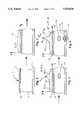
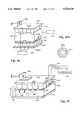
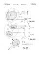
- FIG. 1is a schematic representation of a model of soft "tissue” illustrating a device for loading incorporating pressure sensors used in the present invention
- FIG. 2is the device of FIG. 1 after loading the tissue, and illustrating a typical pressure curve across a surface of the tissue;
- FIG. 3is similar to the tissue compression in FIG. 2, with the effect of a presence of a tumor in the tissue illustrated;
- FIG. 4is an illustration of the structure shown in FIG. 3, with a piston deforming tissue from a side opposite from the pressure plate;
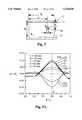
- FIG. 5is a schematic illustration of loading parameters for a model tissue being examined and a tumor in such tissue
- FIG. 5Ais a plot of calculated pressure relationships across the surface at differing ratios of moduli of elasticity ratio between surrounding tissue and a tumor;
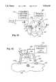
- FIG. 6is a graphical representation of the calculated relationship between pressure ratios and moduli of elasticity ratios for a loading structure shown in FIG. 5;
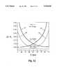
- FIG. 7is a schematic representation similar to that shown in FIG. 5 with certain loading parameters illustrated;
- FIG. 7Ais a graphical representation of the calculated pressure relationships across the surface at differing depths of a tumor in tissue shown at FIG. 7;
- FIG. 8is a graphical representation of calculated pressure relationships relative to the diameter of a tumor being sensed at differing depth of the tumor as shown in FIG. 5;
- FIG. 9is a graphical representation of the calculated pressure relationships relative to the diameter of a tumor, at differing ratios of moduli of elasticity between the surrounding tissue and the tumor;
- FIG. 10is a schematic representation of a block of tissue having a tumor therein with a "finger" inserted from a side opposite from a loading plate;
- FIG. 10Ais a graphical representation related to FIG. 10 illustrating an increase of the resolution of the pressure relationship across the surface relative to position at two different depths of the probe illustrated in FIG. 10;
- FIG. 11is a graphical representation of a portion of tissue with pressure sensors on each of the loading plates
- FIG. 11Ais a graphical representation of the pressure relationships and sensitivity relative to the distance of a tumor from the sensors being used at differing ratios of moduli of elasticity between the surrounding tissue and the tumor;
- FIG. 12is a graphical representation illustrating the sensitivity to the depth of a tumor as related to the size of the tumor as shown in FIG. 11;
- FIG. 13Ais a graphical representation of tissue positioned over underlying objects such as ribs, and being loaded in accordance with the present invention
- FIG. 13Bis an illustration similar to that shown in FIG. 13A with the outer surface of the tissue shifted relative to the supporting ribs;
- FIG. 13Cis a graphical representation of the changes in pressure profile after a shift of the outer surface of the tissue has been made as shown in FIG. 13B;
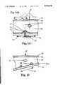
- FIG. 14illustrates a section of tissue being held against a support plate wherein a roller can be rolled along a pad directly applying deformation forces to the section of tissue;
- FIG. 14Ais a graphical representation of the moved stress curve in a X-axis direction with a hardened area or tumor being moved by the roller of FIG. 14;
- FIG. 15is illustrative of a deformation device which includes two round rods that provide pressure at known spaced apart pressure lines;
- FIG. 16is a schematic representational view of force-applying plates similar to that shown in FIG. 5 or FIG. 11 having an array of sensors thereon on at least one of the plates;
- FIG. 17is a schematic representation of a multiplicity of individual actuators compressing a portion of tissue against a reaction plate having an array of pressure or force sensors;
- FIG. 18is a modification of the device of FIG. 17 showing actuators on both the top and bottom, wherein the actuators have force sensors directly thereon;
- FIG. 18Ais an illustration of pressure sensors on the end of an actuator rod
- FIG. 19is a representation of a typical arrangement that uses stepped or smaller diameter end pistons
- FIGS. 20A, 20B and 20Care representations of the device utilizing a pivoting support plate relative to a fixed pressure sensor array
- FIGS. 20A-1, 20B-1 and 20C-1are graphical representations of a moving of the typical stress-related curve relationship of the tissue along a horizontal line illustrating the effect of a moved hardened lump on an image of the tissue cross section of FIGS. 20A, 20B and 20C respectively;
- FIGS. 21A, 21B and 21Care variations of the structures shown in FIG. 20 with pivoting or movable plates on both the top and bottom of the section of tissue being analyzed with FIG. 21B being an illustration wherein at least one of the plates can be made up of several sections which are provided for deformation of the tissue in a different configuration;
- FIG. 22is a schematic representation of a deformation device for intracavity use such as e.g. in a rectum and made according to the present invention
- FIG. 23is a cross-sectional view of the device shown in FIG. 22;
- FIG. 24is a schematic longitudinal sectional view of the device shown in FIG. 23;
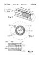
- FIG. 25is a perspective view of a cuff having pressure sensors thereon, and pressure-applying means made according to the present invention.
- FIG. 26is a sectional view of the device of FIG. 25;
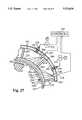
- FIG. 27is an enlarged fragmentary sectional view of a modified form of the invention, illustrating pressure sensors mounted on the interior thereof;
- FIG. 28is a sectional view of a limb with a pad type pressure array held in place against a limb;
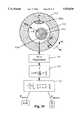
- FIG. 29is a schematic representation of a cross-sectional view of a blood vessel with a plague and including a box diagram for determining the ratio of shear moduli of the plaque and vessel based on the calculating shear component of strain on the boundary between the plaque and the vessel;
- FIG. 30is a schematic representation of a combined system deformation device in which a pressure sensor array located on top of the tissue and an ultrasonic scanner is located below the tissue on a side opposite from the pressure sensor array;
- FIG. 31is a cross-sectional view schematically depicting a pressure sensor array positioned on top of a tissue block with an ultrasonic scanner is disposed on a side of the tissue with the tissue supported by an irregular surface;
- FIG. 32is a cross-sectional view schematically depicting the strain profiles resulting from compression of a tissue block with a tumor therein and the effect on the tissue layers;
- FIG. 33is a schematic representation and cross-section depicting a block of tissue with two tumors therein being compressed with a scanner adjacent the tissue for monitoring tissue displacement;
- FIG. 34Ais a schematic representation of a portion of tissue before compression with certain strain parameters illustrated
- FIG. 34Bis a schematic representation of a portion of tissue during compression with certain strain parameters illustrated
- FIG. 34Cis a diagram illustrating a profile of a strain ratio along a vertical Z axis to illustrate relative hardness of tumors like that shown in FIG. 33;
- FIG. 35is a schematic representation and cross-section of a tissue block with a compressional plate thereon and a scanner device located therebelow;
- FIG. 36is a graphical representation of the deformation of tissue surrounding the tumor relative to normal tissue located away from the tumor as a function of the distance from the center of the tumor;
- FIG. 37is schematic representation and cross-section of a tissue block with tumor therein compressed by a piston with a scanner supporting tissue;
- FIG. 37Ais a graphical representation of the deformation of tumorous tissue relative to surrounding tissue as a function of the relative distance of the tumor from the upper tissue surface;
- FIG. 38Ais a schematic representation of a scanner located on the tissue with a compression plate supporting the tissue in an off-axis manner;
- FIG. 38Bis a schematic representation and cross-section of a tissue block with tumor therein under a compressive load with a scanner on a side of the tissue at an angle relative to the compression device;
- FIG. 38Cis a schematic representation of tissue under the loading shown in FIG. 38B with the compressed tissue shown in phantom with angular strain parameters illustrated;
- FIG. 38Dis a graphical representation of the relative deformation of tumorous tissue relative to surrounding tissue observed as a function of the angle ⁇ of a scanning axis relative to a compressive axis as shown in FIG. 38C;
- FIG. 39is a schematic representation in perspective of a tissue block under compression between force applying plates similar to those in FIG. 36 and with a scanner transversely movable across an upper plate, and including a box diagram flow chart for determining the ratio of modulus of elasticities based on calculating inclusion boundaries;
- FIG. 40Ais a graphical representation of a ratio of modulus of elasticities corresponding to boundaries of an inclusion along a Y axis
- FIG. 40Bis a graphical representation of a ratio of modulus of elasticities corresponding to inclusion boundaries along a Y axis for a hard tumor and a soft tumor;
- FIG. 40Cis a graphical representation depicting a tumor in a three dimensional coordinate system
- FIG. 41is a top plan view of a section of human tissue having a deformation device utilizing suction and made according to the present invention in place thereon;
- FIG. 42is a sectional view of the device shown in FIG. 41 as seen on line 42--42.
- Pressure patterns together with initial boundary conditionscan enable one to reconstruct internal structures in underlying tissue and evaluating relative hardness and softness of tissue in localized areas.
- the present inventionexpands on teachings of how tissue abnormalities can be detected and, as will be shown, the present invention recognizes that the displacements of localized areas inside of tissue and the stress pattern in the tissue are inter-related and that this relationship forms the basis for a method of detecting and quantifying tissue abnormalities based on elasticity difference evaluation.
- the method of analysis of the present inventionis widely applicable and may be used as with pressure sensing arrays, in combination or separately, with virtually any type of imaging (e.g., ultrasound (US), magnetic resonance imaging (MRI), computer aided tomography (CAT)), or other types of information input.
- USultrasound
- MRImagnetic resonance imaging
- CATcomputer aided tomography
- ⁇ ijare components of stress tensor (stress).
- Bulk compressional modulus in tissueis many orders of magnitude higher than shear elasticity modulus as defined by Poisson's ratio of 0.5.
- boundary problem for a system of equations in partial derivativescan be obtained.
- the technique of solving such boundary problemsis well developed and can be used for the obtaining the solution required for elasticity imaging. See Samarski A. A., Nikolaev E. S., The Methods of Solving of Equations in Finite Differences, M., Nauka, 1978.
- Viscosityaffects the information received because with a viscoelastic tissue, there is a time delay between force application and any displacement that occurs. In a dynamic mode where force is applied in time, the development of stresses in time provides the information on viscosity.
- the shear modulus and Young's modulus of soft tissueare different by a factor of 3, because Poisson's ratio is 0.5. While either modulus can be used for examination of the tissue, Young's modulus is used in the description of the present invention.
- FIG. 1illustrates a portion of a soft tissue 10 that is supported on a thick surface 11 and which supports a flat rigid plate 12 capable of exerting pressure thereon from a force generator 13.
- a series of individual pressure sensors indicated at 15are provided on the bottom surface of the plate 12 to sense pressure in an array across the surface of the tissue block 10.
- FIG. 2represents a pressure (P) profile of homogeneous tissue when deformed.
- FIG. 3illustrates a homogeneous tissue pressure profile in the dotted line and in the solid line the profile of the tissue having an inclusion 18. The difference between these two pressure profiles shown in FIG. 3 contains information on the presence, location, and relative elasticity of inclusion 18 in respect to surrounding tissue 10.
- the strain pattern on the surface of the tissue 10 as shown in FIG. 3is in this case represented in the form of pressure profile P(x). This strain pattern depends on the presence of an inclusion 18, as well as on the dimension of the tissue portion, neighboring anatomical features of that tissue, such as presence of a bone, and on the geometrical relationship of the tissue portion 10, support member 11 and deformation member 12.
- FIG. 4schematically illustrates how the present invention enhances the amplitude of the pressure profile and, thus, improves detection of an inclusion.
- the tissue 10is supported on a base 11, and a schematically shown piston or block 24 which also is called a "finger" as used in palpation, is provided on the base and is caused to protrude into the tissue and compress the tissue in a localized area indicated at 26 directly below the tumor 18.
- the represented pressure profile schematically disposed on the top of the pressure plate 12(which is displaced the same as that previously explained) represents the data provided by the pressure sensors 15.
- P(x)is represented as a dashed line and is the profile substantially as that shown in FIG. 3.
- P*(x), indicated by line 28,represents the pressure profile resulting from the presence of the piston 24 directly under the tumor.
- the piston 24acts like a probe to cause extra compression in the desired region (e.g., tumor 18) in addition to the general compression of the tissue block 10 between plate 12 and surface 11. This results in a substantial increase in the pressure profile P*(x) which reaches a maximum at P* max directly over the tumor.
- one aspect or embodiment of the present inventionis to provide an amplification of the pressure signals by using a probing piston on a side opposite from the pressure sensor to cause extra deformation in a region where a tumor occurs. Moreover, by using a number of pistons in an array, and altering the pressures or displacements caused by the pistons, location of a tumor can be more readily determined because of the larger amplitude pressure signal in the area of an inclusion caused by these extra compressive forces.
- FIGS. 5-13are schematic examples to illustrate the applicability of the theory to the methods and devices disclosed, and to show the range of variables and measured parameters available for calculating meaningful values for quantitative analysis and evaluation.
- the illustrations of tissueare not meant to represent any particular portion of a human body. Clinically, the illustrations of FIGS. 1-22 are closely applicable to examining tumor characteristics in breast tissue.
- FIG. 5a schematic representation illustrates tissue having a tumor therein of a certain size and location.
- the graph of FIG. 5Aillustrates a particular calculated differential pressure ratio as a function of the distance along the horizontal axis on the surface of the tissue. The graph is based on the dimensions shown in FIG. 5 having certain values, such as those listed in FIG. 5A.
- the symbol (E)represents the elasticity modulus (Young's modulus) of the tumor and (E o ) represents the elasticity modulus (Young's modulus) of the surrounding tissue.
- a ratio of these two moduli of elasticity (E/E o )provides an indication of the hardness of the tumor relative to the surrounding tissue.
- FIGS. 5 and 5Aillustrate that the differential pressure profile ratio, namely ( ⁇ P/P o ), (a change in amplitude of the pressure sensed at occlusions divided by the pressure in that region of normal tissue) in the region surrounding the tumor is quite sensitive to changes in the elasticity modulus ratio (E/E o ).
- a "block" of tissue 10has a height H from a base to the contact point with the pressure sensors 15, and has a length L extending along the "X" direction (i.e., horizontal axis).
- a tumor 30is positioned in the tissue 10, and is located a distance below the loading plate 12 equal to (h) and it has a diameter (d). Tumor 30 is located along the horizontal axis at a distance (a) from a left edge of the tissue 10.
- FIG. 5Ais a graph illustrating the differential pressure ratio ( ⁇ P/P o ) (values shown on the vertical axis), as a function of the distance along the X axis from the left edge of the tissue 10 to the right.
- the position of the tumor 30 at (a)is indicated by a vertical dotted line in FIG. 5A.
- Several plots of ( ⁇ P/P o ) as a function of (X/L)are shown, each corresponding to a given ratio of moduli of elasticity (E/E o ), which indicates the relative hardness between a tumor and normal tissue.
- the plotsillustrate that a tumor/tissue combination having an elasticity moduli ratio (E/E o ) of only 1.5, i.e., the tumor having a modulus of elasticity of 1.5 times that of the surrounding tissue, a detectable change in the pressure signal is observed for the region surrounding the tumor.
- E/E oelasticity moduli ratio
- a tumor in a breastfor example, can be detected by a palpation (which is the only technique available for evaluating elasticity), but palpation is reliable only when the tumor has progressed so its Young's modulus is more than five to ten times larger than that of surrounding tissue.
- the differential pressure signal ( ⁇ P/P o )shows a more pronounced effect near the tumor when the elasticity moduli ratio (E/E o ) is 2 or 5 or more.
- E/E oelasticity moduli ratio
- FIG. 6illustrates the changes in pressure sensed as a function of the change in the elasticity modulus ratio (E/E o ).
- FIG. 6shows that easily achievable resolution of a few percent in the pressure profile ratio ( ⁇ P/P o ) can enable one to detect inclusions differing from the surrounding tissue in hardness to an extent which does not permit palpatory detection.
- the graphis based on a tissue block 10 having the parameters such as indicated on FIG. 6.
- the values on the horizontal axis (E/E o )are provided on a logarithmic basis to facilitate comparison purposes.
- FIGS. 7 and 7Aillustrate that the capability to detect a tumor within a block of tissue depends on the distance of the tumor from the tissue surface (skin) and pressure sensors.
- the block of tissue 10has a tumor 30 located therein and, in this instance, the vertical height of the tumor is represented as d1 and the lateral width of tumor is represented as d2.
- the parameter (a)represents the tumor's distance from its position from the left side of the tissue block.
- a set of values for the dimensions shown in FIG. 7are listed on in FIG. 7A.
- FIG. 7Ashows the calculated plot of the pressure profile ratio ( ⁇ P/P o ) (the change in pressure of tumorous tissue relative to normal tissue divided by the pressure sensed with no tumor) as a function of (X/L) along the X axis.
- FIG. 8illustrates the effect on the ability to ascertain a change in pressure with the sensors 15 as a function of the change in the diameter d of the tumor.
- the pressure ratio ( ⁇ P/P o ) at the point of surface above the tumor,is indicated along the vertical axis, while the diameter of the tumor d is indicated along the horizontal axis.
- the reference line indicated as 35is more or less the base line for sensitivity of the ratio ( ⁇ P/P o ) measurement that can be easily obtained with existing pressure sensors.
- An error of about one percent in pressure sensorsis quite common, even with very miniature sensors, and the base line 35 represents a change of about three percent, which will give a clear indication of the presence of a tumor in normal tissue having a diameter (d) in the range of one to two millimeters.
- FIG. 8indicates that, the larger the tumor, one observes greater change in the pressure ratio.
- FIG. 9again illustrates the change in the pressure profile ratio ( ⁇ P/P o ) at the point of surface above the tumor as a function of the diameter (d) of the tumor.
- the depth (h) of the tumor below the sensors 15is set at 10 mm and a plot is provided for the case when the elasticity moduli ratio (E/E o ) equals 5 (indicated by line 38) and when (E/E o ) equals 2 (indicated by dashed line 40).
- FIGS. 10 and 10Aillustrate the effects of measuring the pressure profile on tissue having an inclusion while providing a "finger” probe or a piston from an opposite side from the main support 12.
- the sensor array 15is again in place on the support 12, and the tissue block 10 has tumor 30 located therein.
- the dimensional notationsare the same as those previously used.
- a finger probe 42is applied through the base support into the tissue block 10 as shown, and the penetration distance is labeled as (S).
- the finger probeis illustrated as being directly below the tumor 30, which has a diameter of (d).
- FIGS. 10 and 10Aprovide an example of the sensitivity on the pressure sensors when a finger probe or piston has been applied from an opposite side from the pressure sensing array 15. Taking standard dimensions as shown in FIG. 10A, and with an elasticity moduli ratio (E/E o ) of 5, and the diameter of the finger probe (1) as 10 mm, the graph reflects the differences in pressure sensed along the X axis.
- the horizontal axisis X/L
- the vertical axisis ⁇ P*/P.
- the plotted curverepresents the pressure profile ratio ( ⁇ P*/P) as a function of distance along a horizontal axis.
- This graphillustrates that the use of a finger probe, which simulates a probing human finger applied to tissue, accentuates the pressure profile differential in the location of the tumor, making the tumor even easier to detect than without the probe.
- FIGS. 11 and 11Aillustrate that pressure profile sensitivity can be enhanced by having pressure sensor arrays on both sides of the tissue block.
- the plate 12 and pressure array 15would be on top of tissue block 10, and a second plate 44 having a pressure array 45 thereon is below and supporting tissue block 10.
- the block of tissue 10 with the tumor 30 thereinwill be compressed a desired amount.
- the dimensional notationsare also as shown before.
- the graph of FIG. 11Aillustrates the pressure profile ratio ( ⁇ P/P o ) at the point of surface above the tumor (i.e., sensitivity) change as a function of the height h, which is the distance from the top of the tumor 30 to the upper pressure array 15.
- the height H of the tissue blockis a nominal 50 mm and the tumor has a diameter (d) of 10 mm.
- Calculated valuesshow a decrease in the sensitivity of pressure changes measured by the top pressure array 15 as h increases (from 5 to 45 mm).
- Plots 46 and 48illustrate a decrease in measuring pressure sensitivity the further the tumor is away from the upper pressure array 15.
- the plots 50 and 52respectively, show the increase in sensitivity for detection of a tumor at the bottom pressure arrays 45 when the tumor is closer to the pressure array 45.
- the elasticity moduli ratio (E/E o )is 5 for line 50 and the elasticity moduli ratio is 2 for line 52. Accordingly, when the sensitivity of a single pressure array decreases because the tumor is far from the tissue block surface, one can compensate by adding a second pressure sensor array so that a pressure sensor array is on each side of the tissue block being sensed.
- the curve corresponding to the pressure sensed by the pressure sensing array 15is illustrated by curves 54 and 56, and it shows the pressure sensed decreasing as h (the distance between the tumor and array 15) increases.
- the curve 56illustrates this relationship with the tumor having a diameter (d) of 5 mm and curve 54 corresponds to the tumor having a diameter (d) of 10 mm.
- Curve 58illustrates the sensitivity of the bottom pressure sensing array 45 (FIG. 11) with a diameter of the tumor at 10 mm and the curve 60 illustrates the sensitivity at the array 45 with the tumor having a diameter of 5 mm.
- FIG. 12shows that a greater pressure change is sensed for larger diameter tumors.
- the distance between the tumor and bottom array 45decreases resulting in higher measuring sensitivity from the bottom.
- FIGS. 13A, and 13Billustrate a tumor in tissue located on the chest adjacent to ribs
- FIGS. 13B and 13Cillustrate that shifting of the pressure sensor while contacting the tissue accentuates sensitivity of detection for the tumor.
- a rib cage 64is illustrated schematically as having two ribs 66 shown in cross-section and held adjacent to each other with normal connective tissue.
- a quantity of tissuesuch as breast tissue, is indicated at 68 and is positioned between the ribs and an outer surface of the tissue, against which a pressure plate 70 is placed, which has a pressure array 72 thereunder. Force is applied as indicated by the arrow 74 in FIG. 13A.
- a tumor 76is located adjacent to and midway between the ribs 66.
- the distance between the centers of the ribsis indicated as (a), and the width of the ribs is indicated as (1).
- the height of each rib above the general support plane of the tissueis indicated by (S).
- the profile of pressure sensed by an array 72is indicated at the top of FIG. 13A, with the maximum pressure detected corresponding to a position directly above the tumor 76.
- the lateral shift of the pressure plate 70 and pressure sensor 72can be measured from a starting value. Although a lateral shift occurs in the X direction, the amount of shift will be indicated by "Z" in FIG. 13C.
- the increase of pressure sensitivity ( ⁇ P*/P)is marked on the vertical axis, and the horizontal axis indicates an X dimension, which has a zero point at the peak pressure in FIG. 13B.
- the graph of FIG. 13C calculated with the use of the mathematical approach described aboveillustrates the change in pressure profile ( ⁇ P*/P) (after a lateral shift of the pressure plate 70) as a function of the distance X laterally away from the center of the pressure profile peak for P*(x).
- Plot 78illustrates this relationship for a lateral shift of 7 mm of the pressure plate relative to the stationary rib cage (the difference shown between FIGS. 13A and 13B), and plot 80 corresponds to a lateral shift of 18 mm.
- the distance between the center of the ribs (a)is 25 mm and (1), which is the width of the rib, is 20 mm.
- the other dimensional parametersare illustrated at FIG. 13C.
- the graphsindicate that a greater pressure measuring sensitivity is achieved in detecting a tumor in a breast (or other tissue) when the pressure plate is shifted laterally while in contact with the tissue. This is particularly true when the underlying tissue includes a bony structure such as ribs which are adjacent the tumor and over which the tumor will be moved during the shift.
- the form of the invention shown in FIGS. 13A, 13B and 13Cis especially useful for imaging of breast tissue with tumors situated close to the chest.
- a tumoris close to a rib (see FIG. 13A) the approach described above and shown in FIGS. 1-12 as well as ordinary probe techniques, such as palpating or conventional ultrasound, cannot detect the presence of the tumor.
- the pressure sensing plate 70, having pressure sensor 72 thereonis rolled transversely to the ribs (i.e., the lateral shift) the tumor can be detected easily because of an increased resolution created by rolling the tissue.
- the ribacts much like the piston/probe 24 shown in FIGS. 10 thereby accentuating the peak of the pressure profile corresponding to the location of the tumor or inclusion.
- the function P*(x)is shifted laterally reflecting that the peak and baseline of the pressure profile shift. This indicates that there is a harder portion of tissue between the ribs and the surface being pressed upon. If lumps are discovered in this manner, mammography or ultrasound can be utilized for analyzing the internal structures in the region of interest.
- FIG. 14a device is shown schematically wherein a roller is moved along a section of tissue, and analysis of the differing pressure patterns is made while the roller is being so moved.
- a support plate 82has a number of force sensors 84 thereon in a desired array, and the support plate 82 which also can be backed by a movable force-applying member, is acting against tissue 86.
- a tumor 87is located in this tissue.
- the lower supportis a flexible or semi-rigid sheet 91 against which a roller 92 is pressed through the use of a support carriage 90 mounted on a suitable track 93 for movement in direction laterally as indicated by the double arrows 95.
- the roller 92will thus roll along the tissue and cause a raised area 94 of the pad or support 91 to exert a greater deformation of the tissue 86 in a localized area immediately above the roller.
- the tumor 87will tend to shift from the dotted line position shown at 87, and the stress relationship (as graphed in FIG. 14A) will also shift as the tumor shifts, giving an indication that there is some type of a dislocation in the tissue or different hardness tissue that will shift when the roller is rolled. Again an examination of the stress relationship can be used for determining presence of a tumor, evaluating their hardness and making judgments about its character.
- FIG. 15is a slightly modified form of the invention from that shown in FIG. 14, and includes a support plate 82 having pressure sensors 84 thereon, against which a tissue 86 is pressed.
- the exertion of forcecan be merely reaction, with the lower plate shown at 95A being capable of being moved toward the support plate 82 as well as moved in directions indicated by the arrow 97.
- a pair of rods that are indicated generally at 96 and 98can be used for applying localized increased loads or increased deformation of the supporting tissue 86 to increase (to a certain extent) the ability to detect the presence of a tumor 87 in such tissue and decrease the error in calculating relative elasticity of the tumor due to the higher gradients of mechanical stresses in the tumor due to higher vicinity of the rollers or rods.
- FIG. 16a simplified structure for applying deformation to living tissue wherein a quantity of tissue indicated generally at 110 is placed against a support member 112, and a pressure plate 114 is applied to an opposite side of the tissue.
- Tissue 110could be breast tissue or could be muscle tissue from a forearm or upper arm, or the like.
- the edges of the tissueare shown as being defined by boundaries which comprise skin 116.
- the ends of the tissuecould be joined with covering tissue such as skin or joined to other tissue, and could still connected to the human body.
- the section illustratedis merely intended to be illustrative of the principles involved.
- a force-generating device 118such as a load frame or compression loading frame, which is servo-controlled to provide a known amount of force indicated by the load arrow 120, will be applied to the tissue.
- the force generator deviceis capable of being relaxed as desired.
- the support plate 112has an array of individual pressure sensors 122, each of which will provide an individual signal along a line 124 to signal processing equipment 126.
- the equipment 126can provide signals to suitable control systems such as in a computer or right back to the operator, so that the operator can adjust the pressure levels to achieve the desired pressure or force across the surface of the support pad 112 which altogether will provide obtaining pressure profiles over the surface of the of the tissue and calculate three-dimensional distribution of internal structures and their relative elasticities.
- suitable pressure sensors indicated at 128also can be carried on the plate 114 in order to increase resolution in detecting deeply situated tumors and evaluating their elasticity, as it was illustrated in FIGS. 11 and 11A.
- FIG. 16represents a direct force application and a pressure or force readout system that gives the ability to analyze internal structure variations and calculate elasticities of these structures using the data on pressure variations across an array.
- the pressure sensor arraycan be on both sides of the tissue.
- FIG. 17illustrates a variation of the device of FIG. 16, and can include the same type of a backing plate 112, but in this instance the plate 114 and load member 118 are replaced by a backing plate 132 which can be adjustably fixed in spaced relation to the support plate 112, for example, by an adjustable bracket 134.
- the plate 132has a number of individual fluid pressure actuators 136 mounted thereon in an array, and as shown, they are closely spaced. Each of the actuators is formed with a piston on the interior of a cylinder, and each piston has an outer rod portion 138 that has an end surface engaging tissue (indicated at 140) which is supported on the plate 112.
- the individual actuators 136have controls 142 controlling suitable servovalves 143 to, in turn, control the fluid pressure in each of the actuators and thus to control the force applied in a local area by the end of the rod.
- a force feedback sensor indicated at 144is provided to determine the force exerted by each actuator. Sensor 144 in turn provides a feedback signal along a line 146 to the controls 142 to indicate whether or not a pre-programmed force from a program for operation of each actuator is being met.
- These control systems for actuatorsare closed loop servosystems. Separate channels are used for each actuator and the pressure will be adjusted to equal the desired pressure. Closed loop servosystems generally use hydraulic actuators so that precise piston position, as well as the load can be obtained.
- the position of the rod ends 138can be sensed relative to the base plate 132 by using position sensors that can be internal of the actuators, that is, internally located within the cylinders, to sense the position of the respective pistons relative to the base plate 132.
- position sensorscan be internal of the actuators, that is, internally located within the cylinders, to sense the position of the respective pistons relative to the base plate 132.
- Such a sensoris illustrated schematically at 150 and will provide feedback signals to the controller 142 as well.
- the control of actuator position and/or forcepermits simulation of palpation by varying the force on each actuator to achieve the desired compression or displacement of underlying tissue.
- FIG. 18is a schematic representation of a further embodiment of the invention which includes actuators on the top and bottom of the tissue being examined.
- the actuators shown at 136are the same as those of the device of FIG. 17, and can be programmed and controlled as shown in FIG. 17.
- the rod end 138A shown on the top of the tissue in FIG. 18is extended more fully to provide a greater displacement to the tissue 140 than in the form of the invention shown in FIG. 17.
- the ends 138A of the rodscan be formed to have a plurality of individual resistance stress gauge sensors, or some type of a force deflectable diaphragm sensor to sense forces in a localized area on the end of the rod, or to sense total force being exerted by the respective rod.
- FIG. 18Aillustrates such an arrangement, where individual force sensors 160 are on the end of the rod 138A to sense forces in a localized area.
- the second array of actuators 162is mounted on a support plate 164 that in turn is formed and supported on a suitable base that is fixed relative to the support member 134 for plate 132.
- the actuators 162have rod ends 166 that are operated with an internal piston, and can have force sensors 160 on the end as shown in FIG. 18A, as well as internal pressure sensors for determining the total force being exerted by each piston on the tissue 140.
- Displacement sensorsalso are utilized with the rods 166 to determine the position of the end of the rod relative to the base plate 164.
- the force and displacement sensors on the actuatorprovide feedback signals for control, while sensors 160 indicate variation in reaction forces in regions of tissue being displaced.
- the actuatorscan be controlled to extend some of the rods 138 a greater amount relative to others. Also, the controls can cause some to extend a greater amount on the bottom of the tissue, as illustrated.
- Actuators 162A and 136B, at the bottom and top,illustrate probing to change conditions for examination of elasticity of the tissue in the manner described above. Examination can take place also by the use of a suitable imaging apparatus illustrated generally at 170.
- the imaging apparatus 170 to evaluate changes of strain profiles during loading of tissuecan be selected from known devices, such as MRI or ultrasonic imaging devices.
- FIG. 19shows a modification of the actuator construction, and is similar to FIG. 17.
- This embodimentincludes a base plate 112 for supporting tissue 140, and a reaction plate 132 that is suitably supported on a support bracket 134.
- the individual actuators 180are mounted onto the plate 132 in a conventional manner, and have outer cylindrical housings 182.
- the housings 182have internal pistons that actuate rods 184 with smaller diameter end portions 188.
- the pressure in the interior cylinderis controlled through a suitable servovalve 192, respectively, to control the force indicated by the arrow 196 on the piston.
- the portions 188can be separate pistons nested in the main piston 184.
- Suitable known controls 198are provided for controlling the servovalves (one for each actuator) and for receiving feedback signals along lines from pressure sensors 186 that sense pressure in each of the respective actuator chambers, and displacement sensors 187 which provide displacement feedback signals.
- the feedback signals relating to displacement from sensors 187indicate the position of the respective piston rod 184 and smaller end portion 188 relative to the base of the associated cylinder housing 182.
- the controls 198which are conventional servovalve feedback error signal controls, can regulate the position of each of the piston rods individually, as well as the force being exerted by the pistons, and relate that force to the piston rod position.
- the actuatorscan be operated to all be at the same position, or selectively at differing positions to provide for differing strain pattern distributions on tissue 140 that can be sensed by a suitable scanner such as an ultrasound scanner 199 or an MRI scanner.
- FIGS. 20A, 20B, and 20C and corresponding pressure pattern graphs at 20A-1, 20B-1 and 20C-1show the effects of modifying the locations and directions of force, and the movement of a tumor during differing force direction applications.
- FIGS. 20A, 20B and 20Cshow a support plate 200, which is shown in a fixed, generally horizontal position in each of the figures.
- the plate 200has an array of pressure sensors 201 thereon for sensing the pressure exerted toward the plate 200 on a section of tissue 202.
- a tumor 202Ais shown in this tissue, and it can be determined that the tumor will shift from a rest position when loaded with a pivoting plate such as that shown at 203.
- the pivoting platecan be mounted on a central axis or pin 203A and a torque to pivot the plate is created to tilt the plate first in one direction as shown in FIG. 20A, then to hold it steady as shown in FIG. 20B, and then to tilt in the other direction is shown in FIG. 20C.
- the shifting of the peak of the surface pressure distribution caused by the shifting of tumor 202Acan be observed, as shown in 20A-1, 20B-1 and 20C-1.
- Pressure or force changesare sensed by the sensors 201, and an analysis of the elasticity of the tumor 202A, and its relative size can be made from the information contained in the graphical representations of FIGS. 20A-1, 20B-1, and 20C-1.
- FIG. 20BA schematic representation is shown in FIG. 20B of a typical pivoting support and drive.
- the supportincludes a loading support base 204 that can be adjusted to provide for different total loads on the tissue through the use of actuators 204A.
- the actuators 204Acan be adjusted to bring plate 203 closer to or farther away from the backing plate 200, so that at a centered position of the pivoting plate 203, in particular, the total force applied to the tissue could be changed.
- the tilting of the support plate 203can be carried out through the use of a lever 204B that is drivably mounted on the support pins 203A.
- the lever 204Bis operated with an actuator 204C that in turn is supported on the loading plate 204. In this manner, the total load on the tissue can be changed and the plate pivoted to provide for differing angular loading conditions as desired for determination of the presence of, and characteristics of the tumor 202A.
- the graphs 20A-1, 20A-2 and 20A-3show shifting positions of pressure peaks P max when the pivoting plate causes a shifting of the tumor. This aids in determining presence of a tumor, as well as its characteristics.
- FIGS. 21A, 21B and 21CEssentially the same type of loading arrangement is present in FIGS. 21A, 21B and 21C, but in this case, both the plates engaging the tissue may pivot relative to each other.
- Support plate 200Ahas pressure sensors 201 thereon, as previously explained, but it is in turn supported for pivotal movement relative to its support 200B, and can be pivoted through the use of an operator as shown in FIG. 20B, and can have adjustments as to its deformation of the tissue 202.
- the lower plate 203can be mounted just as shown in FIG. 20B.
- the different loading directionsensure a variety of load conditions for enhanced analysis.
- FIG. 21Ba modification of the lower plate is shown, and it includes three separate small pivoting plate sections 205A, 205B and 205C which can be individually pivotally to create variations in force across the width of the tissue 202 that is being examined.
- FIGS. 22, 23 and 24a perspective view of a bodily conduit such as e.g. rectum is schematically shown and a device for deforming the bodily conduit wall tissue and sensing forces on internal wall structures is illustrated.
- the systemincludes a center probe or core 208 that has an array of pressure sensors 207 positioned annularly around it, along a desired length.
- These pressure sensors 207can be mounted on a band of material that wraps over the expandable probe and supports with pressure or force sensors formed or supported onto the exterior of the layer of material.
- the pressure array sold by Tekscan Incorporated, 451 D Street, Boston, Mass., U.S.A.can be used.
- Polyamide filmsalso have been used with strain gauges formed on the surface.
- the supporting band for the sensorscan be a thin steel-band wrapped over the probe and capable of expanding when the probe is expanded.
- the bandcan have a longitudinal gap that separates as the probe expands. The band and/or the probe resist inward forces without deflecting when the probe is expanded while the pressure sensors sense pressure in localized areas.
- the pressure sensor array 207is illustrated as being thicker than that which is normally used, but if desired, the sensor array can have a thickness so that the pressure sensor regions 207A can be made as deflecting diaphragms and utilized for sensing individual forces that are exerted radially inwardly along an annular wall of a bodily conduit 216, such as a rectum.
- the probe or core 208as shown, is tubular and has a central passageway 208A, with a wall 208B that can be expanded after positioning it in the lumen, either by applying internal pressure or by mechanically expanding the diameter a known amount.
- FIG. 23which is a cross-sectional view
- the wall of the conduit 206is engaged by the pressure sensing array 207.
- the conduit wallcan be stretched a known amount after the pressure sensing array 207 and the probe 208 are inserted.
- the probeis expandable at least a known amount so the pressure pattern can be determined when a known displacement of the vessel wall has occurred.
- a radially segmented probe of substantially rigid sections as shown at 208A in FIG. 24can be used.
- the segments 208Aare retained together annularly and can be collapsed inwardly for insertion into the conduit and then expanded a known amount by use of a cam or wedge plug on the interior.
- FIG. 24a schematic representation of a cam and plug type expander is shown.
- Each segment 208Acan have a stepped cam-like interior surface formed. These cams are shown at 208B and cause a decrease in internal diameter toward the remote end of the probe.
- a plug 208Cis mounted in the interior of the probe 208 and can be slid longitudinally with a control rod 208D after the probe is inserted in the conduit.
- the segments 208Awill expand radially outwardly.
- the expansioncan be done in steps so that initial contact with the conduit wall 206 can be made (as recorded by the pressure sensors) and then a known expansion or displacement of the conduit wall can be made.
- the pressure profile around the conduitcan be determined.
- a pressure containing bag or interior coveringcan be used on the interior of the probe or core to pressurize the probe from the interior and provide expansion and loading against the conduit wall when a steel band is used to support the pressure sensors from local inward deflection.
- a tumor or lesion indicated at 209 on one side of the conduit wallwill cause a localized different surface pressure reaction than normal tissue around the wall.
- Each of the individual sensors 207A forming the arrayis capable of sensing pressure or force in a localized area of the conduit wall.
- the probe 208includes means for applying internal force to move the pressure sensors against the surface of the bodily conduit, and thus create a variation in forces being sensed by the sensors.
- the pressure pattern across the array of sensors 207A(as a function of pressure or displacement of the probe wall) will indicate temporal and spatial features of conduit wall elasticity.
- the pressure profilewill be analyzed as previously explained, for indicated differences in the elasticity of the conduit wall 206 and an inclusion (e.g. a prostate tumor) 209.
- the pressure signalscan be quantified by a recorded history of the pressure matrix of a conduit wall and a computerized analysis determination can be made to provide diagnostic information.
- Other conditionsalso can be evaluated by using the pressure sensors 207A such as muscle condition, which will be reflected by pressure patterns obtained during different muscle conditions, such as contraction and relaxation.
- the structure and viscoelastic properties of underlying tissuescan be visualized and analyzed.
- Suitable signal carrying wirescan be mounted through the center of the probe and lead to exterior circuitry.
- Each of the individual sensorsalso can be expanded by injecting fluid into the interior when such sensors are formed as closed elastic chambers. Increased radial pressure can be exerted by inflating the tube or probe 208 when it is made of elastic material to expand it outwardly due to internal pressure.
- the analysiscan be made as previously explained, and by varying the deformation of the conduit wall 206, the differences in resistance to deformation of the tumor 209 will be seen as a change in pressure in that region.
- deformation forcebe applied from the exterior of tissue as in earlier embodiments of the present invention (e.g. embodiment of FIG. 16), but it also can be applied from the interior of tissue structures (e.g. within a lumen of a bodily conduit) such as with the device described in connection with FIGS. 22-24.
- FIGS. 25 and 26Another embodiment of the present invention in which deformation can be applied from the exterior of a tissue body is shown in FIGS. 25 and 26.
- a limb of a humansuch as an arm indicated at 210 is shown.
- the underlying tissueis indicated at 212 below the skin surface. Blood vessels are adjacent the skin, as is normal.
- the limb 10is encircled with a cuff-like assembly 214, which can be fastened in place, and which is made to include inflatable chambers.
- the cuff assemblyincludes an outer wrap 216, as shown, which completely covers the outer surface 218 as shown in FIG. 26 of an inner inflatable chamber 228.
- wrap 216could be a series of spaced straps that encompass the periphery of the chamber outer surface 218.
- the chamber 28has end walls 220 and 222, which define, in conjunction with an inner wall 224 and an outer air-tight wall 226, which is sealed to inner wall 224 at its edges 225A and 225B, the interior chamber 228 that can be filled with a suitable pressurized fluid such as air, provided through an adjustable regulator 230 from a pressure source 31 through a connecting line 232.
- the inner wall 224is made of a suitable radial force resisting material to which individual pressure sensors indicated at 234 can be adhered.
- the wall 224can be suitable plastic (or a thin wall steel band) that is rigid enough to resist forces exerted by a vessel or muscle through the skin surface on the pressure sensors, and will reduce in circumference enough to be forced against the skin from pressure in chamber 228, while generally conforming to the overall curved shape of the limb.
- the wrap 216is sufficiently strong to resist outward forces as chamber 228 is pressurized.
- the pressure sensors 234are designed to sense pressure in localized areas, and as shown the array of pressure sensors extends substantially around the limb, except for the place where a longitudinal gap 236 (FIG. 26) is provided between the edges 225A and 225B. The gap permits the wall 224 to reduce in circumferential size as it is forced inwardly under pressure in the chamber 228.
- the overwrap 216can be formed of a suitable non-stretchable material if desired and fastened together where the overwrap overlaps, which is that region 216A, with suitable fasteners such as hook-and-loop fasteners sold under the trademark VELCRO, or any other suitable fasteners.
- suitable fastenerssuch as hook-and-loop fasteners sold under the trademark VELCRO, or any other suitable fasteners.
- the pressure sensors 234can be of any desired design, such as small sensors that have deflecting diaphragms with strain gauges on the diaphragms, or capacitive sensors that are miniature in size. These sensors are quite sensitive to determining changes in pressure. For example, one can use sensors such as those incorporated into a Tekscan Industrial Sensing System (for pressure distribution measurement) available from Tekscan, Inc. of Boston, Mass. These sensors are grid-based sensors having a 44 by 44 grid and available in different spatial resolution (e.g., 0.050", 0.075", 0.100") and different sensitivities.
- the sensorscan be arranged in an array comprising rows along the length or longitudinal axis of the cuff as shown in FIG. 25 at 240.
- Each of the sensorsis individually instrumented, to provide signals to suitable signal conditioning equipment 242, and then each pressure signal can be provided to a diagnostic computer 243.
- a representation of the change in the amount of blood pressure in vessels under the cuffcan be determined.
- the sequence of pressure sensed in each row of sensors extending along a blood vesselwill indicate a blood pressure propagation wave, the amplitude of the wave, the timing or frequency of the succeeding waves, all their temporal and spatial features and changes that occur at different loadings on wall 224.
- the pattern of the stresses detected by the sensors of the arraycan be related to the strain in the underlying tissue, its structure and mechanical properties.
- the force of wall 224 against the skinalso will change, allowing one to obtain such stress and strain information, and evaluate anatomical structure and viscoelastic properties of underlying tissues.
- the array of pressure sensorscan be selected in size as desired.
- the length of the array extending along the longitudinal axis of the wristmay be five to ten centimeters and may include about five sensors extending along the longitudinal axis of the wrist and ten to twelve sensors extending about a periphery of the wrist.
- the number of sensors useddepends upon the size of each sensor (not all sensors need be the same size), the condition being evaluated (e.g., blood pressure, muscle elasticity), and the preference of the investigator.
- a cuff 249has a pressure bag or container and an outer wall 250 joined to an inner wall 252 with a suitable number of longitudinal dividers 254. End walls at the opposite ends of the chamber are sealed so that the chamber of the cuff holds fluid under pressure, as previously explained.
- the inner wall 252 of the chamberbears against a segmented wall 253, formed much like longitudinal strips extending along the length of the cuff.
- the wall segments 253each carry a plurality of pressure sensors 256 thereon. These pressure sensors 256 can be adhered to the wall 253, and may include deflecting members 258, supported on a rim-type edge of a housing 260 that defines an interior cavity 262.
- the deflecting member 258deflects and acts as a diaphragm when subjected to pressure against the skin indicated at 263 surrounded by the cuff.
- Longitudinal members 254divide the cuff into a plurality of individual longitudinally-extending chambers 264, 266 and 268 as shown, and each of these chambers is above one of the segments of wall 253.
- the chamberscan each have a suitable inlet valve 270 that is controlled through an individual fluid pressure valve 272 and 274, as shown, so that the individual pressures in the chambers 264, 266 and 268 can be changed. This will permit one to vary the internal pressure and thus the force exerted on the skin along a wall segment 253, at selected positions around the circumference of the cuff, for obtaining different types of imaging from the pressures or forces sensed by the individual pressure sensors 256.
- Each of the pressure sensors 256has wires or leads 278 to carry signals from the deflecting diaphragm. These leads 278 extend outwardly through the outer wall 250 through a sealed connection 279 to prevent pressure leaks and are connected to additional suitable leads leading to controls indicated at 280.
- the controls 280can be used for controlling the valves 272 and 274, and for recording, using, and maintaining the various pressure signals that are obtained from each of the individual pressure sensors.
- the cuffis attached easily and can be used much like an ordinary blood pressure measuring cuff (e.g. sphygmomanometer cuff).
- the cuffcarries individual pressure sensors for sensing pressures on localized areas of the skin (that is surrounded by the cuff) to obtain blood pressure propagation wave pattern having temporal and spatial characteristics. This pattern can be analyzed to indicate information about the circulating system of the patient being analyzed.
- FIG. 28another modified form of the invention is illustrated.
- an array of pressure sensorsare mounted on an individual pad, and held in place with a suitable overwrap.
- the pad indicated at 281can have a plurality of individual sensors 282 thereon, which are positioned adjacent the blood vessel 283 on an arm 284.
- the pad 281can be constructed similarly to that shown in the previous figures, and in this case if desired the pad can be made in a rigid shell that conforms to the shape of the arm, and the band 285 can be used for applying differing pressures to the pad.
- an inflatable bagcan be placed between the band 285 and the pad 281 so that the bag can be inflated to exert different pressures on the pad.
- the band 285is non-stretchable to react the forces and can be held in place at an overlapped portion 89 of the cuff through the use of suitable fasteners.
- the blood flowing in the vessel 283will create changes in pressure patterns which can be used to obtain an objective evaluation of circulatory conditions.
- all forms of the inventionallow one to register temporal and spatial orientations of blood pressure flow under differing loading to obtain a multiparameter description of the state of the circulatory system.
- Such data accumulated over time in parallel together with diagnostic information provided by experts on pulse diagnostics (and confirmed by conventional methods)are used to form the computerized analyzation system for correlative evaluation of the particular bodily condition present in the patient.
- the cuffas shown, also can be used for determining pressure pattern changes due to other responses below the skin, such as determining functional state and physiological responses of the muscles in investigated area of limb.
- the cuffcan be much shorter than shown.
- the cuffincludes a desired means for permitting it to be fastened in place surrounding a portion of a limb for analyzing the mechanical properties and structure of tissue under the cuff by measuring pressure pattern changes while regulating and changing the pressure or force exerted on the skin.
- Individual sections of the cuffcan be controlled by providing multiple individual inflatable chambers instead of a single inflatable chamber to permit non-uniform forces to be exerted on the limb.
- the structureprovides the ability to quickly apply the pressure sensing array and then vary the pressure conveniently.
- the ease of use of the inventionleads to wide adaptability.
- Individual pressure sensorspermit an array of sensors to analyze conditions in localized areas of the tissue surrounded by the cuff.
- the variations in deformation needed for analyzing tissue for areas of differing elasticitymay be the result of blood pressure changes in a blood vessel such as shown in FIG. 29.
- a phased array ultrasonic scannercan be carried on the interior of an endovascular probe and provide imaging of the lumen wall during blood pressure variations.
- FIG. 29illustrates one method of evaluating mechanical properties of the internal structure of a tissue body. The method is based on evaluating the strain on the individual tissue particles before and during compression of the tissue (compression by blood pressure cycling) by observing differences in images of the tissue obtained before and during tissue compression.
- FIG. 29presents the method as applied to a bodily conduit wherein a radial coordinate system is used for tracking movement of the tissue particles of the tissue body.
- FIG. 29shows a two dimensional (i.e., cross-sectional) image of a vessel 316 having a plaque 309A formed on a wall of the vessel.
- a scanner 316Sis schematically illustrated as being located in a catheter 314 positioned in the lumen of the vessel 316.
- the symbol ⁇designates a boundary between the plaque 309A, which has a shear modulus designated as ⁇ * , and the vessel tissue 316, which has a shear modulus designated by ⁇ o .
- the following description in connection with FIG. 25is intended to be merely illustrative of the principles involved in evaluating the elasticity of internal structures of a tissue body and is discussed as a simplified two-dimensional approach.
- a method of determining the relative shear modulus between the plaque 309A and the vessel 316can be performed in the following manner.
- a scanner 316Sis used to produce a two-dimensional image of a cross-section of the vessel wall and plaque, such as that cross-section shown in FIG. 29.
- tissue particlesare identified in the image of the vessel and plaque which have a horizontal and a vertical dimension, or any two dimensions which are perpendicular to each other.
- the wall of the vessel 316will expand and contract in accordance with the rise and lowering of the blood pressure through the vessel.
- the first image just discussedwould be obtained when the vessel wall is contracted i.e., when the blood pressure is at its lowest in a cardiac pulsation cycle.
- Another image of the cross-section of the vessel 316is obtained when the vessel wall is expanded, i.e., at the peak of the blood pressure cardiac pulsation cycle.
- the components of displacement u,vcan be expressed as components of displacement in a radial direction (r) and in azimuthal direction ( ⁇ ).
- the methodincludes determining the components of displacement for each tissue particle in the vessel and plaque and relating the displacements in terms of the components r and ⁇ .
- a shear component of the deformation tensoris obtained by relating the displacement in the u,v directions to the r, ⁇ directions as shown by the equation in box 312 in FIG. 29.
- This shear component of the strain or deformation tensoris represented by the symbol ⁇ as a function of a point (r, ⁇ ).
- This shear component ⁇can be obtained for each tissue particle in the vessel and plaque, however, obtaining the shear component for each tissue particle is not necessary. Instead, only the shear components on either side of the boundary ⁇ are of interest.
- shear component of the tissue particlescan restrict an analysis of the shear component of the tissue particles to a comparison of the shear component of a tissue particle of the vessel 316 at the boundary ⁇ to the shear component of a tissue particle of the plaque 309A at the boundary ⁇ which is adjacent to the identified vessel tissue particle.
- a shear component of a tissue particle of the plaque 309A at the boundary ⁇ , which is adjacent the vessel tissue particle at (R+ ⁇ r, ⁇ )can be determined through the equation in box 312 and the shear component of this plaque tissue particle is calculated for a point (R- ⁇ r, ⁇ ).
- the shear component ⁇ (R+ ⁇ r, ⁇ )to the shear component ⁇ (R- ⁇ r, ⁇ ) in terms of a ratio as shown in box 313, one obtains a value which corresponds to a ratio ( ⁇ * / ⁇ o ) of the shear modulus ( ⁇ *) relative to the shear modulus ( ⁇ o ).
- This ratio ( ⁇ * / ⁇ o )indicates the relative shear modulus between the plaque 309 and the vessel 316.
- the exact values of ⁇ * and ⁇ ocan be obtained by solving the general equations for non-compressible media discussed and illustrated previously. However, if the internal pressure P is unknown, the relative modulus of elasticity of the vessel and the plaque can only be evaluated in terms of a numerical value of the ratio ( ⁇ * / ⁇ o ) that was determined by comparing the shear component of adjacent tissue particles on opposite sides of the boundary ⁇ as represented by the equations in box 313.
- Combined systemscan be utilized including pressure sensors that determine surface conditions, and scanners such as MRI, x-ray or ultrasound scanners which provide information about deformations and corresponding strain profiles of internal structures under various loading conditions.
- the pressure sensing arrayscan indicate stress profiles on the surface and the conventional scanners give information about the changes in geometry of any internal structures and corresponding strain pattern.
- the calculation of elasticities of internal tissueswill be performed with higher resolution and, additionally, regions of interest in the images produced by an imaging device can be characterized in the terms of relative elasticity or hardness. This will increase diagnostic capability of the existing imaging methods in tumor diagnostics.
- FIGS. 30 and 31a combined system is illustrated.
- a mass of tissue indicated at 320is supported on a suitable support 322, which has a scanner 324 mounted thereon on a bottom side, or from an opposite side from the tissue.
- the tissueis compressed with a support plate 326 that has a plurality of individual pressure sensors in an array indicated generally at 328.
- the pressure array at the surface as shownprovides a pressure distribution depending on the structure and elasticities of internal tissues.
- the pressure sensing arrayprovides the data for structure and elasticity evaluation as it is described in the co-pending application Ser. No. 07/823,155.
- the scanner 324(which can be an ultrasound scanner, a magnetic resonance imager, or a CAT scanner) identifies the geometry of the internal tissues and can be used for detection of boundaries between tissue of different elasticity and obtaining the strain pattern so that the inverse problem can be solved easier.
- FIG. 31is a modification of the device in FIG. 30 and includes a pressure plate 330 acting on tissue 320, which is supported on a support plate 334 in the model shown, which is simulating soft tissue to which access can be provided from one side and on the opposite side supported by skeletal elements, such as the bone structure.
- the support platecan have an irregular surface, representing a bony or skeletal structure underlying investigated soft tissues. This results in a different pressure profile being measured from the pressure sensors 336 (on the bottom of the plate 330).
- a scanner 338which is positioned alongside the tissue and angled relative to the tissue, can be used for imaging the changes in the internal geometry of the tissue 320 under different loading conditions to obtain the internal strain profiles.
- the scannercan be of any desired form, but by analyzing both the stress pattern on the pressure sensors 336 and the internal strain patterns from the scanner, the condition of any inclusion in the tissue can be determined.
- This informationincludes the elasticity information and can include positional and dimensional information about the inclusion.
- FIG. 32a representation of strain pattern or other profile in a compressed tissue 320 is shown with an inclusion 321 (e.g., cross section of bone, tumor, or fibrous tissue) therein.
- the plate 342can be moved in vertical direction as indicated by the arrow F 1 .
- the tissue 320is supported on a suitable support 340.
- the strain profiles of tissueare depicted (indicated at 344) internal of the tissue 320 and above, below, or in both sides of the inclusion 321. These strain profiles would appear on the image produced by a scanner 338 and relative deformation of this lines after loading the tissue will depend on the mechanical structure of tissue.
- the inclusionhas a complex structure, i.e., has a variety of tissue hardness or has a complex shape which is not uniform, then the known displacements of the nearest layers or the other structures give the possibility to determine more exactly the properties of this complex inclusion.
- FIGS. 33, 34A, 34B and 34Cillustrate that analysis of the changes in dimension of portions of tissue in vector directions can be used for determining the presence of a tumor and its mechanical properties. This technique can be applied even to dimensional changes that are on the surface remote from the inclusion.
- a plate 346is positioned to compress tissue 348 against a support plate 350.
- a scanner 352is positioned on the opposite side of the support plate from the tissue.
- FIG. 34Aillustrates a particle of uncompressed tissue with dimensions a and b that are equal.
- the particleUnder a compressive load (as shown by the arrows (R) in FIG. 34B), the particle will compress in the u (e.g. vertical) to dimension a 1 and expand in the v direction (e.g. horizontal) to dimension b 1 .
- the actual volume of the inclusiondoes not change, but the dimensions of the particles in the vector directions (u,v) shift.
- the changes in the shape of a given tissue particle before and during compressioncan be determined through comparing images (obtained by a scanner) of the internal structure of the tissue before and during compression. Monitoring the relative changes of tissue particle dimensions can be accomplished through various methods e.g. by speckle tracking technique in the case of ultrasonic imaging.
- speckle tracking techniquesare discussed in the following publications: J. Meunier and M. Bertrand, Ultrasonic Speckle Motion Inherent to Tissue Motion: Theory and Simulation, Proceedings of the 1989 IEEE Ultrasonics Symposium 0090-5607-89, pp. 865-868 (1989); and M. Bertrand, J. Meunier, M. Doucent and G. Ferland, Ultrasonic Biomechanical Strain Gauge Based on Speckle Tracking, Proceedings of the 1989 IEEE Ultrasonics Symposium 0090-5607-89, pp. 859-864 (1989).
- the detection of strain patterns in the compressed tissuecan be evaluated by so-called "tagged imaging". See e.g. E. A. Zerhouni et al., Human Heart Tagging With MR Imaging--A Method for Noninvasive Assessment of Myocardial Motion, Radiology Vol. 169, 169-172 (1988) and J. G. Pipe et al., Method for Measuring Three-Dimensional Motion With Tagged MR Imaging, Radiology Vol. 181, 591-595 (1991).
- the imaging analysis of the deformation of the tissue particlecan provide a strain characteristic denoted ⁇ and equal to the ratio of the (a 1 ) (vertical) and (b 1 ) (horizontal) dimension.
- FIG. 34Cillustrates a ratio of strain characteristic of an inclusion within the tissue ( ⁇ ) to the strain characteristic of normal tissue ( ⁇ o ) as shown in FIG. 33 (during compression) as a function of distance (Z) from the top array 346.
- the strain ratio ( ⁇ / ⁇ o )is measured along the horizontal axis and position along the Z axis is measured in the tissue corresponding to a vertical line extending from the top of the tissue through inclusion A and to the bottom of tissue 248 (See FIG. 33).
- the strain profileshows that the strain characteristic of tissue particles of the inclusion ( ⁇ A ) is less than strain characteristic of tissue particles of normal tissue ( ⁇ o ), as indicated by the curve 354 peaking to the left.
- the strain characteristic ⁇is related to the modulus of elasticity, this relationship between the strain characteristics ⁇ A and ⁇ o means that inclusion A has modulus of elasticity (E A ) higher than that of normal tissue (E o ), and therefore inclusion A must be harder than normal tissue.
- the projectionshows that in the region adjacent the perimeter of the inclusion, the strain of surrounding tissue is affected so that the behavior of the tissue near the tumor is affected by the presence of the tumor.
- the strain characteristic for these regions adjacent the perimeter of the inclusion Aare shown at 354B and 354C and similar regions are shown for inclusion B at 356B and 356C. Accordingly, to identify the presence and approximate location of an inclusion within a tissue portion, one can compare the strain characteristic between adjacent tissue particles to identify regions within the tissue portion that have tissue particles with a strain characteristic significantly different than the strain characteristic of tissue particles throughout the remaining tissue portion.
- the regions 354B and 354C and regions 356B and 356C of FIG. 34Ccorrespond to transitions between tissue particles of an inclusion and tissue particles of surrounding normal tissue.
- the transitionapproximately defines a region of tissue particles having a strain characteristic (e.g. the strain characteristic ⁇ A for tissue particles of inclusion A) that is significantly different from the strain characteristics of the tissue particles for the surrounding remainder of the tissue portion (e.g. the strain characteristic ⁇ o for the tissue particles of normal tissue).
- a strain characteristice.g. the strain characteristic ⁇ A for tissue particles of inclusion A
- This information based on monitoring strain variationsaids in determining the relative tissue elasticity through imaging by being able to define the changes in dimensions of portions of tissue by tracking points visible in the image projected.
- Other types of analysiscan be carried out to determine elasticity by establishing grids of points as is done by tagged MR imaging technique and analyzing a number of points across the plane of the tissue. The original markers inside the living tissue also can be used.
- This method of identifying a region of different elasticity within a tissue portion by determining strain characteristic values of compressed tissue particlesis not confined in its application to the configuration shown in FIG. 33.
- the scannerneed not be positioned on a top or bottom of a plate supporting the tissue.
- the methodalso can be applied in the configurations like that shown in FIG. 31 (or FIGS. 38A and 38B) in which the scanner for producing images of the tissue is positioned on a side of the tissue at an angle to the axis of compression of the tissue. Images produced by this "side" scanning are equally suitable for analysis to determine the displacements of tissue particles in terms of "horizontal” and “vertical" dimensions (i.e., the u,v directions).
- the orientation of the u,v vectorscan be rotated to make the analysis more convenient.
- this methodis illustrated in FIG. 33 for analyzing a two-dimensional image of the internal structure of the tissue.
- the scanner in FIG. 33can be moved in the third dimension as desired so that the method can be applied to as many two-dimensional images of the tissue along the third dimension as is necessary to make a three-dimensional reconstruction, determine the boundary of the inclusion in three dimensions under various loading conditions and then solve general equations for the linear theory of elasticity and evaluate elastic moduli of inclusion and surrounding tissues.
- this methodcan be applied to any of the configurations discussed in which a scanner is used to image the strain profiles in the internal structure of the tissue to determine elasticity within the tissue, i.e., it can be used in conjunction with FIGS. 29-32 and those to be discussed in FIGS. 35-38 and 41-42.
- the method of evaluating inclusions as illustrated in FIGS. 33, and 34A-34Cis advantageous where it is particularly difficult (in the case of very complex inclusion-having a very non-uniform surface) to determine the exact boundary of the inclusion.
- the methodconveniently yields information sufficient to determine the presence, location, approximate boundary, and relative modulus of elasticity of a region of tissue having different elasticity than the surrounding tissue.
- FIGS. 35 and 36illustrate the behavior of tissue near an inclusion when imaging and identifying boundaries of internal structures of the tissue and the ability to find a lump or tumor upon compression because of distortion or disturbances of tissue adjacent to the tumor.
- This illustrationis based on the use of data which can be obtained by any technique enabling one to detect displacements of a given point of internal tissue, such as speckle tracking in the case of ultrasonic imaging or "tagged imaging” using MRI as noted in the literature mentioned above.
- FIG. 35shows a portion of tissue 370 that is compressed with plate 372 with a scanner 374 provided for imaging the tissue.
- An inclusion 376has dimensions as shown, and a modulus of elasticity E, with the surrounding tissue having the modulus of elasticity E o .
- the quantity R illustrated in FIG. 35is the distance from the center of the inclusion.
- the quantity ( ⁇ / ⁇ o )is plotted on the vertical scale, and R is shown on the horizontal scale.
- the plot 377illustrates the relationship between the ratio of strain ( ⁇ / ⁇ o ) as a function of distance R when the diameter of the inclusion is 10 millimeters.
- the curve or plot 379corresponds to an inclusion having a diameter of two millimeters.
- the ratio of the change of points between those parallel to the direction of compression force and those perpendicular to the direction of compression force(i.e., a, b, respectively in FIGS. 34A and 34B) provides for an indication of the relative modulus of elasticity of the inclusion/surrounding tissue and makes the inclusions visible in an imaging analysis.
- This graphillustrates that the presence of a small tumor can be detected by analyzing tissue deformation beyond the edges of the tumor.
- the graph of FIG. 36indicates that as the distance increases between the points being tracked and the tumor the observer loses definition of the tumor boundary but yet can get enough information to indicate the presence of some type of an inclusion.
- This imaging shown in FIG. 35 utilizing the analysis presented in FIG. 36can be performed in three dimensional form for early detection of very small tumors.
- FIGS. 37 and 37Aillustrate quantitatively the depth sensitivity of relative deformation.
- a tissue mass 380is supported on a support 381 with a scanner 382 below the support for imaging the internal structure of the tissue 380.
- a piston or probe 384which has a diameter D, presses on the outer surface and compresses the tissue above a tumor 386 (or other inclusion).
- the tumorhas a dimension in the Z or vertical direction of d 1 , and a horizontal or transverse dimension of d 2 .
- the tissuehas an uncompressed height of H, and the distance from the top of the tissue mass to the center of the tumor in the Z or vertical direction is recorded as h.
- Example dimensions for the piston, the tumor and Hare provided in the graph of FIG. 37A. A ratio of the moduli of elasticity of 0.25 between the tumor and surrounding tissue is assumed.
- the graph curve 386shows the effect that the distance from the probe 384 to the tumor has on the measured relative deformation ( ⁇ / ⁇ o ) between the tumor and normal tissue.
- the ratio of (h/H)is plotted on the horizontal scale and ratio of ( ⁇ / ⁇ o ) is plotted on the vertical scale.
- the curve 386shows that as the tumor is closer to the probe, the change in strain of the tumor relative to the strain of the surrounding tissue is greater when the distance of the tumor from the piston 384 is less.
- tissue 390is supported on a pivoting plate 392, (similar to that shown in FIG. 21) as it is being compressed. Compression on the tissue acting on the tumor 394 while pivot plate 392 is tilted at an angle will cause an image resulting from a scanner 396 that is different than an image resulting from straight compression along the Z or vertical axis.
- the effect of an angular application of forcealso is related to (or analogous to) the action as shown in FIG. 38B where compression remains in a vertical plane while the scanner axis is disposed at various angles relative to the compression axis. This can be done by moving the scanner along various locations on the surface of the tissue.
- tissue 400is supported on a support 401 which could be also an internal skeletal structure, and is compressed with a probe or piston 402 along the vertical axis.
- a scanner indicated at 404 for imaging the internal structure of the tissueis positioned at an angle relative to the vertical axis that is shown as theta ( ⁇ ).
- the scannerhas a scanning axis that intersects the tumor 406.
- FIG. 38CThe effect of compression on such a tumor is shown in FIG. 38C where the dotted line representation shows the configuration of the tumor after compression, and the solid line representation shows the tumor prior to compression.
- the line A 1 -B 1is the Z axis or the direction of force application (also indicated by the arrows) and the line A 2 -B 2 is the scanning axis.
- the angle theta ( ⁇ )is the angle between the compression axis and the scanning axis.
- Line 407 in FIG. 38Dillustrates that the strain determined for normal tissue ( ⁇ o ) varies little as the scanning axis is rotated relative to and away from the compression axis as maximum measured by the angle ( ⁇ / ⁇ ).
- line 408 in FIG. 38Dshows that the strain determined for an inclusion ( ⁇ ) varies greatly depending on the angle ⁇ of rotation of the scanning axis relative to the compression axis.
- FIGS. 35-38The effects shown on FIGS. 35-38 are enhanced proportionally with increasing the range of deformations.
- FIGS. 39 and 40describe evaluation of boundaries between portions of tissue differing in elastic modulus and estimating the signs of changes of elasticity of tissue along chosen lines in the image of the compound tissue.
- FIG. 39is an illustration of tissue compressed where a scanner can be moved linearly transversely to the direction of compression.
- tissue 410is supported on a support plate 411 and is loaded with a compressing plate 412, using a known force generator to compress the tissue 410 a desired amount.
- a scanner 414is slidably mounted for movement in the direction as indicated by the arrows 415 along a Z axis (as illustrated in the vector diagram adjacent the drawing). Moving the scanner in this way corresponds to movement of the scanner in the third dimension as discussed in conjunction with FIG. 33.
- a tumor 416 having Young's modulus of elasticity of E 1is positioned in the tissue, and the vector representation for particles of the tissue is three dimensional, including vector directions v, u and w.
- the scannerBy displacing the scanner linearly transversely, three-dimensional information about the tumor and tissue are provided in terms of elasticity modulus by evaluating a series of two-dimensional images of the distortion of particular particles under compression. Even in the case when a tumor cannot be seen directly on the image of tissue, analysis of the distortion of the tissue at various points on a cross-section (i.e., two-dimensional image) of the tissue indicates a boundary between normal tissue and an inclusion.
- FIG. 39illustrates another method of identifying a region of different elasticity within a tissue portion. This method is based on the method discussed in conjunction with FIG. 33. In this method, similar to that discussed in conjunction with FIG. 29, images of the internal structure of the tissue before and during compression of the tissue are compared.
- a speckle tracking technique or similar methodone can define two-dimensional individual tissue particles within the tissue and determine the change in the dimensions of each tissue particle by comparing the before compression and during compression images.
- the change in dimensionscan be expressed as ratio of a horizontal dimension (b 1 ) to a vertical dimension (a 1 ) to yield a strain characteristic value ⁇ equal to (b 1 /a 1 ) for each tissue particle.
- This determinationis represented by the box 413 indicating calculating the local displacement of each tissue particle and box 415 representing an experimentally determined profile or strain function of the strain characteristic value for each tissue particle.
- this methodis the same as the method as was discussed in connection with FIGS. 33, 34A, 34B and 34C.
- the experimental stress-strain factor ⁇can then be determined along a measurement axis at the point (y) by calculating a ratio of the experimental strain characteristic at the point (i.e., tissue particle) (y+ ⁇ y) over the experimental strain characteristic at the point (i.e., tissue particle) (y- ⁇ y).
- the stress-strain factor ⁇ for each adjacent pair of tissue particles along the y measurement axiscan be determined as indicated in box 417.
- the boundary of an inclusion (or tumor 416)can be determined based on the stress-strain factor ⁇ , as indicated in box 418.
- ⁇i.e., a calculated strain characteristic ratio
- a non-unity stress-strain factor (ratio)indicates adjacent tissue particles experiencing different amounts of strain thereby indicating different moduli of elasticity for the adjacent tissue particles. Accordingly, identifying a profile of adjacent tissue particles with non-unity stress-strain factors indicates the boundary between a region having different elasticity (e.g. inclusion) than the remaining surrounding tissue portion (e.g. normal tissue).
- a ratiocan be calculated for a strain value of a tissue particle, the inclusion region over a strain value of the surrounding normal tissue and this ratio will yield a stress-strain factor ⁇ * exp that allows one to determine the relative elasticity of the inclusion and surrounding tissue, because of the strong correlation between the strain characteristic value and the modulus of elasticity for a given tissue particle.
- this relative elasticitycan be expressed as a ratio of the modulus of elasticity (E 1 ) for the inclusion to the modulus of elasticity (E o ) for the surrounding tissue (See box 419 in FIG. 39).
- FIGS. 40, 40B and 40Cgraphical representations are shown for different conditions of relative elastic moduli and illustrate ways of evaluating boundary transitions.
- the stress-strain factor ⁇is plotted on a horizontal axis
- the graph line 420illustrates transitions in terms of a ratio of modulus of elasticity between surrounding tissue and a tumor 421, where a change in elasticity modulus occurs along the Y axis at points Q 2 and Q 1 .
- the elasticity modulus (E 1 ) of the inclusion or tumor 421is greater than that of the surrounding tissue (E o ).
- the ratios of modulus of elasticity of neighboring pointsbecomes smaller than unity at the interface, that is, the base line 420 in FIG. 40A will have left-ward deflection at 420A and when crossing the interface from harder to softer tissue the ratio becomes greater than unity and the base line 420 will have a right-ward deflection 420B.
- This procedurecan be carried out using the apparatus of FIGS. 30 and 31.
- the determination of the pressure pattern simultaneously with the calculation of ratiosincreases the precision of evaluating the elasticity of structures of interest in the imaging.
- the stress evaluationcan be correlated to the plot of ratios to add in resolving the inverse problem.
- FIG. 40Billustrates the case with two inclusions utilizing graph line 422 to reveal transitions between tissues with differing elasticities.
- the modulus of elasticity E 2 of the inclusion or tumor 423is less than that of surrounding tissue (represented as E 0 ).
- the second inclusion 425 shown in FIG. 40Bis of the same condition as that shown in FIG. 40A, where the modulus of elasticity of the tumor is larger than that of the surrounding tissue.
- FIG. 40A and 40Brepresent a graphical analysis determination of the boundaries between surrounding tissue (E 0 ) and an inclusion or tumor (E 1 ). This step corresponds to box 418 in FIG. 39.
- FIG. 40Crepresents the manner of determining of the relative modulus of elasticity of the tumor, as it is schematically shown in Box 419, FIG. 39.
- the value ⁇ *is the value of ⁇ , calculated at the specific point Q of the inclusion's boundary, in which the normal vector n has a component as indicated on FIG. 40C.
- FIGS. 41 and 42present one more example of evaluation of elasticity of inclusions by deforming tissue using a different technique of deformation.
- the technique of deformation presented in FIGS. 41 and 42provides better possibilities for taking advantage of the above described approaches to evaluation of tissue inclusion hardness in the case where access to the tissue is possible from only one surface.
- a section of tissue indicated generally at 450can be tissue covered by skin of a human, such as that of a forearm, leg, or other portion of the anatomy, and is shown only schematically.
- tissue 450is deformed and imaged while the tissue is deformed.
- a suction apparatus indicated generally at 452comprises a dome-shaped cup member 454 having a flange or peripheral rim 456, and a dome-shaped center portion 458 that forms an interior chamber or cavity 460 when the flange 456 is placed against exterior skin or epidermis 462.
- the chamber 460includes a phased array ultrasonic sensor transducer or probe 465 of conventional design.
- a suitable connector 464is used for carrying leads 466 to an ultrasonic imaging circuitry 468 for control and display.
- a fitting 470is used to connect a line 472 leading from a variable negative pressure source 474 (FIG. 42) through the chamber 460, to permit reducing the pressure in the chamber 460.
- a filling valve 476(FIG. 42) is openable to permit filling a suitable liquid media into the chamber 460 that provides a coupling between the ultrasonic transducer 465 and the epidermis 462, and thus to the underlying tissue.
- the tissue 450has a representative tumor 478 therein, relatively close to the epidermis.
- Tumor 478has a different elasticity or elasticity modulus than the surrounding tissue 450.
- the tissue under the cupwill bulge up, or in other words, deform into a bulge indicated generally at 450A in FIG. 42.
- This bulgecauses deformation of tissue, and also causes the tumor 478 to move.
- the tumor 478is of different elasticity than the surrounding tissue, so the amount of deformation is different, and the difference in elasticity will be represented on the image on the ultrasonic display 468 when the ultrasonic probe 465 is operated in a conventional manner.
- the differences in elasticitycan be calculated in the manner presented above based on the difference in strain in the tissue as represented in the image generated by the ultrasonic sensing head. Analysis of the condition of the tissue, the size of the tumor, and other characteristics of the tumor can be made.
- the negative pressure sourcecan be varied by controls 480, which are used to dynamically vary the negative pressure to cause changes in deformation of the tissue, or to maintain the negative pressure and thus the deformation at steady state.
- the steady state value of the negative pressurecan be changed if desired.
- the controlscan be made to interface with the ultrasonic images and go through a sequence of pressure variation or patterns.
- the controlscan be computer controls or manual controls.
- a suction gauge 473also is provided for reference.
- the probe 465is preferably a phased array ultrasonic probe using known circuitry. A wide variety of such imaging devices are available.
- Tissue deformation under the negative pressure produced by the suction cupcan thus be obtained to permit analysis by other imaging modalities such as x-ray or MRI devices.
- suitable sealing agentsthat aid in sealing the rim 456 to the surface of the skin can be utilized, such as petroleum jelly or other sealants that are presently in use for attaching cups to the skin surface.
Landscapes
- Health & Medical Sciences (AREA)
- Life Sciences & Earth Sciences (AREA)
- Engineering & Computer Science (AREA)
- Surgery (AREA)
- Physics & Mathematics (AREA)
- General Health & Medical Sciences (AREA)
- Molecular Biology (AREA)
- Veterinary Medicine (AREA)
- Biophysics (AREA)
- Pathology (AREA)
- Biomedical Technology (AREA)
- Heart & Thoracic Surgery (AREA)
- Public Health (AREA)
- Medical Informatics (AREA)
- Animal Behavior & Ethology (AREA)
- Nuclear Medicine, Radiotherapy & Molecular Imaging (AREA)
- Radiology & Medical Imaging (AREA)
- Remote Sensing (AREA)
- Reproductive Health (AREA)
- Gynecology & Obstetrics (AREA)
- Hematology (AREA)
- General Physics & Mathematics (AREA)
- Radar, Positioning & Navigation (AREA)
- Computer Networks & Wireless Communication (AREA)
- Optics & Photonics (AREA)
- Human Computer Interaction (AREA)
- Ultra Sonic Daignosis Equipment (AREA)
- Measuring And Recording Apparatus For Diagnosis (AREA)
Abstract
Description
Claims (38)
Priority Applications (9)
| Application Number | Priority Date | Filing Date | Title |
|---|---|---|---|
| US07/994,109US5524636A (en) | 1992-12-21 | 1992-12-21 | Method and apparatus for elasticity imaging |
| PCT/US1993/012455WO1994014375A1 (en) | 1992-12-21 | 1993-12-20 | Method and apparatus for elasticity imaging |
| US08/607,645US5785663A (en) | 1992-12-21 | 1996-02-27 | Method and device for mechanical imaging of prostate |
| US08/607,646US5860934A (en) | 1992-12-21 | 1996-02-27 | Method and device for mechanical imaging of breast |
| US08/607,639US5678565A (en) | 1992-12-21 | 1996-02-27 | Ultrasonic elasticity imaging method and device |
| US08/872,561US5836894A (en) | 1992-12-21 | 1997-06-10 | Apparatus for measuring mechanical parameters of the prostate and for imaging the prostate using such parameters |
| US08/872,559US5922018A (en) | 1992-12-21 | 1997-06-10 | Method for using a transrectal probe to mechanically image the prostate gland |
| US08/963,385US5833633A (en) | 1992-12-21 | 1997-11-03 | Device for breast haptic examination |
| US09/359,200US6142959A (en) | 1992-12-21 | 1999-07-22 | Device for palpation and mechanical imaging of the prostate |
Applications Claiming Priority (1)
| Application Number | Priority Date | Filing Date | Title |
|---|---|---|---|
| US07/994,109US5524636A (en) | 1992-12-21 | 1992-12-21 | Method and apparatus for elasticity imaging |
Related Child Applications (3)
| Application Number | Title | Priority Date | Filing Date |
|---|---|---|---|
| US08/607,645Continuation-In-PartUS5785663A (en) | 1992-12-21 | 1996-02-27 | Method and device for mechanical imaging of prostate |
| US08/607,639Continuation-In-PartUS5678565A (en) | 1992-12-21 | 1996-02-27 | Ultrasonic elasticity imaging method and device |
| US08/607,646Continuation-In-PartUS5860934A (en) | 1992-12-21 | 1996-02-27 | Method and device for mechanical imaging of breast |
Publications (1)
| Publication Number | Publication Date |
|---|---|
| US5524636Atrue US5524636A (en) | 1996-06-11 |
Family
ID=25540290
Family Applications (1)
| Application Number | Title | Priority Date | Filing Date |
|---|---|---|---|
| US07/994,109Expired - LifetimeUS5524636A (en) | 1992-12-21 | 1992-12-21 | Method and apparatus for elasticity imaging |
Country Status (2)
| Country | Link |
|---|---|
| US (1) | US5524636A (en) |
| WO (1) | WO1994014375A1 (en) |
Cited By (256)
| Publication number | Priority date | Publication date | Assignee | Title |
|---|---|---|---|---|
| US5678565A (en)* | 1992-12-21 | 1997-10-21 | Artann Corporation | Ultrasonic elasticity imaging method and device |
| WO1997046160A1 (en)* | 1996-06-03 | 1997-12-11 | The Trustees Of The University Of Pennsylvania | Marking tumors and solid objects in the body with ultrasound |
| US5753822A (en)* | 1996-06-04 | 1998-05-19 | Pirelli Reifenwerke Gmbh | Method and device for determining the green tack of rubber blends |
| WO1998015501A3 (en)* | 1996-10-09 | 1998-06-25 | Symyx Technologies Inc | Systems and methods for characterization of materials and combinatorial libraries with mechanical oscillators |
| US5820552A (en) | 1996-07-12 | 1998-10-13 | United States Surgical Corporation | Sonography and biopsy apparatus |
| US5833627A (en) | 1995-04-13 | 1998-11-10 | United States Surgical Corporation | Image-guided biopsy apparatus and methods of use |
| US5833633A (en)* | 1992-12-21 | 1998-11-10 | Artann Laboratories | Device for breast haptic examination |
| US5833634A (en)* | 1995-11-09 | 1998-11-10 | Uromed Corporation | Tissue examination |
| US5851180A (en)* | 1996-07-12 | 1998-12-22 | United States Surgical Corporation | Traction-inducing compression assembly for enhanced tissue imaging |
| WO1999013762A3 (en)* | 1997-09-16 | 1999-06-03 | Uromed Corp | Clinical tissue examination |
| US5916160A (en)* | 1996-04-09 | 1999-06-29 | Arcan; Mircea | Real-time imaging contact gauge and visual feedback interactive apparatus including same |
| US5916180A (en)* | 1997-10-03 | 1999-06-29 | Uromed Corporation | Calibrating pressure sensors |
| US5938613A (en) | 1993-10-29 | 1999-08-17 | United States Surgical Corporation | Methods and apparatus for performing sonomammography and enhanced X-ray imaging |
| US5970789A (en)* | 1996-11-20 | 1999-10-26 | Hill-Rom, Inc. | Method and apparatus for evaluating a support surface |
| US5978695A (en)* | 1997-08-18 | 1999-11-02 | Lucid Inc. | System for imaging mechanically stabilized tissue |
| US5983123A (en) | 1993-10-29 | 1999-11-09 | United States Surgical Corporation | Methods and apparatus for performing ultrasound and enhanced X-ray imaging |
| US5989199A (en)* | 1996-11-27 | 1999-11-23 | Assurance Medical, Inc. | Tissue examination |
| US6027457A (en) | 1998-06-18 | 2000-02-22 | United States Surgical Corporation | Apparatus and method for securing tissue during ultrasound examination and biopsy |
| US6039691A (en)* | 1997-06-02 | 2000-03-21 | Duke University | Kinetic acoustic ocular examination apparatus and method |
| US6063031A (en)* | 1997-10-14 | 2000-05-16 | Assurance Medical, Inc. | Diagnosis and treatment of tissue with instruments |
| USD425980S (en)* | 1997-10-20 | 2000-05-30 | Assurance Medical, Inc. | Hand-held tissue examination device |
| US6101450A (en)* | 1997-06-03 | 2000-08-08 | The Trustees Of Columbia University In The City Of New York | Stress analysis using a defect-free four-node finite element technique |
| WO2000055616A1 (en)* | 1999-03-15 | 2000-09-21 | Societe D'elastographie Impulsionnelle Pour Les Systemes De Mesure De L'elasticite (Seisme) | Imaging method and device using shearing waves |
| US6179790B1 (en) | 1997-10-20 | 2001-01-30 | Assurance Medical, Inc. | Layer of material for use with tissue examination device |
| US6190334B1 (en) | 1999-05-24 | 2001-02-20 | Rbp, Inc. | Method and apparatus for the imaging of tissue |
| US6192143B1 (en)* | 1997-10-24 | 2001-02-20 | Ultratouch Corporation | Apparatus for detecting very small breast anomalies |
| US6270459B1 (en)* | 1998-05-26 | 2001-08-07 | The Board Of Regents Of The University Of Texas System | Method for estimating and imaging of transverse displacements, transverse strains and strain ratios |
| WO2001076484A1 (en)* | 2000-04-05 | 2001-10-18 | Duke University | Method and apparatus for the identification and characterization of regions of altered stiffness |
| US6306658B1 (en) | 1998-08-13 | 2001-10-23 | Symyx Technologies | Parallel reactor with internal sensing |
| US6351549B1 (en) | 1997-10-24 | 2002-02-26 | Ultratouch Corporation | Detection head for an apparatus for detecting very small breast anomalies |
| US6393895B1 (en) | 1997-10-08 | 2002-05-28 | Symyx Technologies, Inc. | Method and apparatus for characterizing materials by using a mechanical resonator |
| US6409684B1 (en)* | 2000-04-19 | 2002-06-25 | Peter J. Wilk | Medical diagnostic device with multiple sensors on a flexible substrate and associated methodology |
| US6455316B1 (en) | 1998-08-13 | 2002-09-24 | Symyx Technologies, Inc. | Parallel reactor with internal sensing and method of using same |
| US20020151782A1 (en)* | 1996-10-18 | 2002-10-17 | Zavislan James M. | System for confocal imaging within dermal tissue |
| US6468231B2 (en) | 2000-03-31 | 2002-10-22 | Artann Laboratories | Self-palpation device for examination of breast |
| US6481268B1 (en) | 1999-10-12 | 2002-11-19 | Baker Hughes, Inc. | Particle measurement by acoustic speckle |
| US20020178787A1 (en)* | 1997-10-08 | 2002-12-05 | Symyx Technologies, Inc. | Method and apparatus for characterizing materials by using a mechanical resonator |
| US6494840B1 (en)* | 2000-07-31 | 2002-12-17 | The Hong Kong Polytechnic University | Portable ultrasonic palpation system |
| US6500119B1 (en) | 1999-12-01 | 2002-12-31 | Medical Tactile, Inc. | Obtaining images of structures in bodily tissue |
| US6508768B1 (en)* | 2000-11-22 | 2003-01-21 | University Of Kansas Medical Center | Ultrasonic elasticity imaging |
| US6511427B1 (en) | 2000-03-10 | 2003-01-28 | Acuson Corporation | System and method for assessing body-tissue properties using a medical ultrasound transducer probe with a body-tissue parameter measurement mechanism |
| US6514204B2 (en)* | 2000-07-20 | 2003-02-04 | Riverside Research Institute | Methods for estimating tissue strain |
| US20030026736A1 (en)* | 1998-08-13 | 2003-02-06 | Symyx Technologies, Inc. | Multi-temperature modular reactor and method of using same |
| US6517486B1 (en)* | 2001-08-16 | 2003-02-11 | Computed Ultrasound Global, Inc. | Compounding method for reducing speckle noise |
| US6524246B1 (en) | 2000-10-13 | 2003-02-25 | Sonocine, Inc. | Ultrasonic cellular tissue screening tool |
| US6548026B1 (en) | 1998-08-13 | 2003-04-15 | Symyx Technologies, Inc. | Parallel reactor with internal sensing and method of using same |
| US6552543B1 (en)* | 1999-08-26 | 2003-04-22 | Siemens Aktiengesellschaft | Magnetic resonance tomography apparatus with vibration-decoupled outer envelope |
| US6569098B2 (en) | 2001-01-31 | 2003-05-27 | University Technologies International Inc. | Non-invasive diagnostic method and apparatus for musculoskeletal systems |
| US6569108B2 (en)* | 2001-03-28 | 2003-05-27 | Profile, Llc | Real time mechanical imaging of the prostate |
| US20030114743A1 (en)* | 2001-12-19 | 2003-06-19 | Kai Eck | Method of improving the resolution of a medical nuclear image |
| US6595933B2 (en) | 2000-03-31 | 2003-07-22 | Artann Laboratories | Self-palpation device for examination of breast with 3-D positioning system |
| US20030156989A1 (en)* | 2000-06-03 | 2003-08-21 | Adam Safir | Parallel semicontinuous or continuous reactors |
| US20030171672A1 (en)* | 2002-03-08 | 2003-09-11 | Tomy Varghese | Elastographic imaging of in vivo soft tissue |
| WO2004000125A1 (en)* | 2000-12-22 | 2003-12-31 | Md Medical Diagnostics Inc. | System and method for analysis of a tissue |
| US20040030672A1 (en)* | 2001-08-01 | 2004-02-12 | Garwin Jeffrey L | Dynamic health metric reporting method and system |
| WO2004002305A3 (en)* | 2002-07-01 | 2004-03-04 | Allez Physionix | Systems and methods for making noninvasive assessments of cardiac tissue and parameters |
| US20040059220A1 (en)* | 2000-11-28 | 2004-03-25 | Allez Physionix Limited | Systems and methods for making noninvasive assessments of cardiac tissue and parameters |
| US20040073106A1 (en)* | 2002-05-22 | 2004-04-15 | Rubicor Medical Inc. | Breast stabilizers having an open lattice structure and imaging methods using same |
| US20040097836A1 (en)* | 2000-10-06 | 2004-05-20 | Ombrellaro Mark P. | Direct manual examination of remote patient with virtual examination functionality |
| US20040099050A1 (en)* | 2002-10-18 | 2004-05-27 | Symyx Technologies, Inc. | Machine fluid sensor and method |
| US20040111027A1 (en)* | 1999-08-23 | 2004-06-10 | Hans Torp | Method and apparatus for providing real-time calculation and display of tissue deformation in ultrasound imaging |
| US20040167403A1 (en)* | 2000-04-05 | 2004-08-26 | Nightingale Kathryn R. | Methods, systems, and computer program products for ultrasound measurements using receive mode parallel processing |
| US6787112B1 (en) | 1998-08-13 | 2004-09-07 | Symyx Technologies, Inc. | Parallel reactor with internal sensing and method of using same |
| US20040211260A1 (en)* | 2003-04-28 | 2004-10-28 | Doron Girmonsky | Methods and devices for determining the resonance frequency of passive mechanical resonators |
| US20040215075A1 (en)* | 2003-04-22 | 2004-10-28 | Zagzebski James A. | Ultrasonic elastography with angular compounding |
| US20040225215A1 (en)* | 2003-01-23 | 2004-11-11 | L'oreal | Skin analysis apparatus including an ultrasound probe |
| US6825838B2 (en) | 2002-10-11 | 2004-11-30 | Sonocine, Inc. | 3D modeling system |
| US20040244487A1 (en)* | 2003-03-21 | 2004-12-09 | Symyx Technologies, Inc. | Mechanical resonator |
| US20040250622A1 (en)* | 2003-03-21 | 2004-12-16 | Symyx Technologies, Inc. | Resonator sensor assembly |
| US20040260180A1 (en)* | 2001-08-20 | 2004-12-23 | Hiroshi Kanai | Tissue identifying method in ultrasonography and ultrasonograph |
| US20040267165A1 (en)* | 2003-06-12 | 2004-12-30 | Sarvazyan Armen P. | Tactile breast imager and method for use |
| US20050004467A1 (en)* | 2003-05-07 | 2005-01-06 | Terumo Kabushiki Kaisha | Ultrasonic diagnostic apparatus and method |
| US20050004463A1 (en)* | 2003-04-09 | 2005-01-06 | Shigao Chen | Method and apparatus for shear property characterization from resonance induced by oscillatory radiation force |
| US20050015009A1 (en)* | 2000-11-28 | 2005-01-20 | Allez Physionix , Inc. | Systems and methods for determining intracranial pressure non-invasively and acoustic transducer assemblies for use in such systems |
| US20050033199A1 (en)* | 2001-08-31 | 2005-02-10 | Van Der Steen Antonius Franciscus Wilhelmus | Three-dimensional tissue hardness imaging |
| US20050049499A1 (en)* | 2003-08-27 | 2005-03-03 | Shay Kaplan | Method for protecting resonating sensors and protected resonating sensors |
| US20050065426A1 (en)* | 2002-05-20 | 2005-03-24 | Vespro Ltd. | Method, system and device for tissue characterization |
| US6875176B2 (en) | 2000-11-28 | 2005-04-05 | Aller Physionix Limited | Systems and methods for making noninvasive physiological assessments |
| US20050085728A1 (en)* | 2003-10-20 | 2005-04-21 | National Institute Of Advanced Industrial Science And Technology | Apparatus and program for estimating viscoelasticity of soft tissue using ultrasound |
| US20050124892A1 (en)* | 2003-12-09 | 2005-06-09 | The Regents Of The University Of Michigan | Methods and systems for measuring mechanical property of a vascular wall and method and system for determining health of a vascular structure |
| US20050145019A1 (en)* | 2002-10-18 | 2005-07-07 | Symyx Technologies, Inc. | Environmental control system fluid sensing system and method |
| WO2005070298A1 (en)* | 2004-01-23 | 2005-08-04 | Koninklijke Philips Electronics N.V. | Ultrasound imaging system for calculating a compression ratio |
| US20050187470A1 (en)* | 2002-06-04 | 2005-08-25 | Jun Kubota | Ultrasonograph, method for displaying information on distortion of biological tissue in ultrasonic image |
| US20050187473A1 (en)* | 2003-07-21 | 2005-08-25 | Boctor Emad M. | Robotic 5-dimensional ultrasound |
| US20050215899A1 (en)* | 2004-01-15 | 2005-09-29 | Trahey Gregg E | Methods, systems, and computer program products for acoustic radiation force impulse (ARFI) imaging of ablated tissue |
| US20050228271A1 (en)* | 2004-04-06 | 2005-10-13 | Diebold Gerald G | Differential x-ray acoustic imaging |
| US20050251042A1 (en)* | 2002-09-06 | 2005-11-10 | Echosens | Device and method for measuring elasticity of a human or animal organ and for two-or three-dimensional representation thereof |
| US20050252295A1 (en)* | 2002-09-02 | 2005-11-17 | Centre National De La Recherche Scientifique- Cnrs | Imaging method and device employing sherar waves |
| US20050265518A1 (en)* | 2004-01-06 | 2005-12-01 | Aubel Leo J | Mammography procedure and apparatus for reducing pain when compressing a breast |
| US20050267368A1 (en)* | 2003-07-21 | 2005-12-01 | The Johns Hopkins University | Ultrasound strain imaging in tissue therapies |
| US20050288590A1 (en)* | 2004-06-28 | 2005-12-29 | Shay Kaplan | Method for protecting resonating sensors and open protected resonating sensors |
| US20060025682A1 (en)* | 2004-07-30 | 2006-02-02 | Ray Vanderby | Method and apparatus providing improved ultrasonic strain measurements of soft tissue |
| US20060052696A1 (en)* | 2002-07-31 | 2006-03-09 | Tsuyoshi Shiina | Ultrasonic diagnosis system and strain distribution display method |
| US20060074311A1 (en)* | 2004-09-27 | 2006-04-06 | Kozo Nakamura | Ultrasonic diagnostic apparatus |
| US7025774B2 (en) | 2001-06-12 | 2006-04-11 | Pelikan Technologies, Inc. | Tissue penetration device |
| US20060079773A1 (en)* | 2000-11-28 | 2006-04-13 | Allez Physionix Limited | Systems and methods for making non-invasive physiological assessments by detecting induced acoustic emissions |
| US20060105357A1 (en)* | 1998-02-18 | 2006-05-18 | Myomics, Inc. | Tissue sensor and uses thereof |
| US7079257B1 (en) | 2002-04-08 | 2006-07-18 | Providence Health System | Methods and apparatus for evaluating mechanical and thermal strains in electronic materials, semiconductor materials, and other structures |
| US7088455B1 (en) | 2002-04-08 | 2006-08-08 | Providence Health Systems —Oregon | Methods and apparatus for material evaluation using laser speckle |
| US20060241447A1 (en)* | 2005-03-31 | 2006-10-26 | Aloka Co., Ltd. And The University Of Tokyo | Ultrasonic diagnostic apparatus |
| US20060245541A1 (en)* | 2004-02-26 | 2006-11-02 | Aubel Leo J | Mammography procedure and apparatus for reducing pain when compressing a breast |
| US20070052970A1 (en)* | 2003-03-21 | 2007-03-08 | Symyx Technologies, Inc. | Resonator sensor assembly |
| US20070055149A1 (en)* | 2003-05-20 | 2007-03-08 | Matsushita Electric Industrial Co., Ltd. | Ultrasonic diagnostic apparatus (as amended) |
| US7198606B2 (en) | 2002-04-19 | 2007-04-03 | Pelikan Technologies, Inc. | Method and apparatus for a multi-use body fluid sampling device with analyte sensing |
| US20070100237A1 (en)* | 2005-10-17 | 2007-05-03 | Yoko Okamura | Ultrasonic diagnostic device and image processing device |
| WO2006012623A3 (en)* | 2004-07-22 | 2007-05-18 | Univ Johns Hopkins | Imaging tissue deformation using strain encoded mri |
| US7229458B2 (en) | 2002-04-19 | 2007-06-12 | Pelikan Technologies, Inc. | Method and apparatus for penetrating tissue |
| US7232451B2 (en) | 2002-04-19 | 2007-06-19 | Pelikan Technologies, Inc. | Method and apparatus for penetrating tissue |
| US7244265B2 (en) | 2002-04-19 | 2007-07-17 | Pelikan Technologies, Inc. | Method and apparatus for penetrating tissue |
| US7258693B2 (en) | 2002-04-19 | 2007-08-21 | Pelikan Technologies, Inc. | Device and method for variable speed lancet |
| US7291117B2 (en) | 2002-04-19 | 2007-11-06 | Pelikan Technologies, Inc. | Method and apparatus for penetrating tissue |
| US7297122B2 (en) | 2002-04-19 | 2007-11-20 | Pelikan Technologies, Inc. | Method and apparatus for penetrating tissue |
| US7297151B2 (en) | 2002-04-19 | 2007-11-20 | Elikan Technologies, Inc. | Method and apparatus for body fluid sampling with improved sensing |
| US7302830B2 (en) | 2001-06-06 | 2007-12-04 | Symyx Technologies, Inc. | Flow detectors having mechanical oscillators, and use thereof in flow characterization systems |
| US7316700B2 (en) | 2001-06-12 | 2008-01-08 | Pelikan Technologies, Inc. | Self optimizing lancing device with adaptation means to temporal variations in cutaneous properties |
| US7331931B2 (en) | 2002-04-19 | 2008-02-19 | Pelikan Technologies, Inc. | Method and apparatus for penetrating tissue |
| US7344507B2 (en) | 2002-04-19 | 2008-03-18 | Pelikan Technologies, Inc. | Method and apparatus for lancet actuation |
| US7344894B2 (en) | 2001-10-16 | 2008-03-18 | Agilent Technologies, Inc. | Thermal regulation of fluidic samples within a diagnostic cartridge |
| US20080081994A1 (en)* | 2006-10-03 | 2008-04-03 | The Regents Of The University Of Michigan | Measurement of tissue elastic modulus |
| US7371247B2 (en) | 2002-04-19 | 2008-05-13 | Pelikan Technologies, Inc | Method and apparatus for penetrating tissue |
| US7374544B2 (en) | 2002-04-19 | 2008-05-20 | Pelikan Technologies, Inc. | Method and apparatus for penetrating tissue |
| US20080125654A1 (en)* | 2006-11-27 | 2008-05-29 | Medison Co., Ltd. | Ultrasound system |
| US7410468B2 (en) | 2002-04-19 | 2008-08-12 | Pelikan Technologies, Inc. | Method and apparatus for penetrating tissue |
| US20080221484A1 (en)* | 2005-05-06 | 2008-09-11 | Sarvazyan Armen P | Method and a dual-array transducer probe for real time mechanical imaging of prostate |
| US20080287792A1 (en)* | 2004-08-27 | 2008-11-20 | Washington, University Of | Ultrasonic Direct Strain Estimation Using Temporal and Spatial Correlation |
| US20080287807A1 (en)* | 2007-05-16 | 2008-11-20 | James Geoffrey Chase | Global motion invariant signatures for fast and accurate motion tracking in a digital image-based elasto-tomography system |
| US20080287780A1 (en)* | 2007-05-16 | 2008-11-20 | James Geoffrey Chase | Integral based parameter identification applied to three dimensional tissue stiffness reconstruction in a digital image-based elasto-tomography system |
| US20090005707A1 (en)* | 2005-05-06 | 2009-01-01 | Sarvazyan Armen P | Method and device for real time mechanical imaging of prostate |
| US7485128B2 (en) | 2002-04-19 | 2009-02-03 | Pelikan Technologies, Inc. | Method and apparatus for penetrating tissue |
| US7491178B2 (en) | 2002-04-19 | 2009-02-17 | Pelikan Technologies, Inc. | Method and apparatus for penetrating tissue |
| US7524293B2 (en) | 2002-04-19 | 2009-04-28 | Pelikan Technologies, Inc. | Method and apparatus for penetrating tissue |
| US7537571B2 (en) | 2001-06-12 | 2009-05-26 | Pelikan Technologies, Inc. | Integrated blood sampling analysis system with multi-use sampling module |
| US20090143679A1 (en)* | 2007-09-28 | 2009-06-04 | The University Of British Columbia | Method and apparatus for imaging the mechanical properties of tissue from an endocavity |
| US20090143675A1 (en)* | 2005-09-20 | 2009-06-04 | Matsushita Electric Industrial Co., Ltd. | Ultrasonic diagnostic apparatus |
| US20090149752A1 (en)* | 2003-05-30 | 2009-06-11 | Takashi Osaka | Ultrasound Probe And Ultrasound Elasticity Imaging Apparatus |
| US7547287B2 (en) | 2002-04-19 | 2009-06-16 | Pelikan Technologies, Inc. | Method and apparatus for penetrating tissue |
| US20090163805A1 (en)* | 2005-11-30 | 2009-06-25 | Matsushita Electric Industrial Co., Ltd. | Ultrasonic diagnostic apparatus |
| US20090171200A1 (en)* | 2007-12-26 | 2009-07-02 | Aloka Co., Ltd. | Ultrasound diagnosis apparatus |
| US20090177083A1 (en)* | 2005-01-26 | 2009-07-09 | Takeshi Matsumura | Pressing Member, Ultrasonic Probe and Ultrasonic Diagnosing Device |
| US20090177084A1 (en)* | 2006-05-25 | 2009-07-09 | Takeshi Matsumura | Ultrasonic Diagnostic Apparatus |
| US20090182234A1 (en)* | 2008-01-15 | 2009-07-16 | Christian Perrey | Method for assessing mechanical properties of an elastic material |
| US7563232B2 (en) | 2002-04-19 | 2009-07-21 | Pelikan Technologies, Inc. | Method and apparatus for penetrating tissue |
| US20090209847A1 (en)* | 2008-02-16 | 2009-08-20 | Geng Li | Magnetic resonance elastograph system with hydraulic driver |
| US20090216123A1 (en)* | 2005-05-09 | 2009-08-27 | Takeshi Matsumura | Ultrasonic Diagnostic Apparatus and Ultrasonic Image Display Method |
| US7604592B2 (en) | 2003-06-13 | 2009-10-20 | Pelikan Technologies, Inc. | Method and apparatus for a point of care device |
| WO2009127071A1 (en)* | 2008-04-18 | 2009-10-22 | Valorbec Societe En Commandite | System for sensing and displaying softness and force |
| US20090281412A1 (en)* | 2007-12-18 | 2009-11-12 | Searete Llc, A Limited Liability Corporation Of The State Of Delaware | System, devices, and methods for detecting occlusions in a biological subject |
| US20090281413A1 (en)* | 2007-12-18 | 2009-11-12 | Searete Llc, A Limited Liability Corporation Of The State Of Delaware | Systems, devices, and methods for detecting occlusions in a biological subject |
| US20090287076A1 (en)* | 2007-12-18 | 2009-11-19 | Boyden Edward S | System, devices, and methods for detecting occlusions in a biological subject |
| US20090287110A1 (en)* | 2008-05-14 | 2009-11-19 | Searete Llc | Circulatory monitoring systems and methods |
| US20090287093A1 (en)* | 2008-05-15 | 2009-11-19 | Searete Llc, A Limited Liability Corporation Of The State Of Delaware | Circulatory monitoring systems and methods |
| US20090292195A1 (en)* | 2007-12-18 | 2009-11-26 | Searete Llc, A Limited Liability Corporation Of The State Of Delaware | System, devices, and methods for detecting occlusions in a biological subject including spectral learning |
| US20090292222A1 (en)* | 2008-05-14 | 2009-11-26 | Searete Llc | Circulatory monitoring systems and methods |
| US20090318802A1 (en)* | 2007-12-18 | 2009-12-24 | Searete Llc, A Limited Liability Corporation Of The State Of Delaware | System, devices, and methods for detecting occlusions in a biological subject |
| EP1418843A4 (en)* | 1999-07-22 | 2010-01-06 | Profile Llc | Device for palpation and mechanical imaging of the prostate |
| US7648468B2 (en) | 2002-04-19 | 2010-01-19 | Pelikon Technologies, Inc. | Method and apparatus for penetrating tissue |
| US20100036209A1 (en)* | 2008-08-07 | 2010-02-11 | Searete Llc, A Limited Liability Corporation Of The State Of Delaware | Circulatory monitoring systems and methods |
| US20100036269A1 (en)* | 2008-08-07 | 2010-02-11 | Searete Llc, A Limited Liability Corporation Of The State Of Delaware | Circulatory monitoring systems and methods |
| US20100036268A1 (en)* | 2008-08-07 | 2010-02-11 | Searete Llc, A Limited Liability Corporation Of The State Of Delaware | Circulatory monitoring systems and methods |
| US7666149B2 (en) | 1997-12-04 | 2010-02-23 | Peliken Technologies, Inc. | Cassette of lancet cartridges for sampling blood |
| US7674232B2 (en) | 2002-04-19 | 2010-03-09 | Pelikan Technologies, Inc. | Method and apparatus for penetrating tissue |
| US7682318B2 (en) | 2001-06-12 | 2010-03-23 | Pelikan Technologies, Inc. | Blood sampling apparatus and method |
| US7699791B2 (en) | 2001-06-12 | 2010-04-20 | Pelikan Technologies, Inc. | Method and apparatus for improving success rate of blood yield from a fingerstick |
| US7717863B2 (en) | 2002-04-19 | 2010-05-18 | Pelikan Technologies, Inc. | Method and apparatus for penetrating tissue |
| US20100137710A1 (en)* | 1996-10-18 | 2010-06-03 | Zavislan James M | System for marking the locations of imaged tissue with respect to the surface of the tissue |
| US7749174B2 (en) | 2001-06-12 | 2010-07-06 | Pelikan Technologies, Inc. | Method and apparatus for lancet launching device intergrated onto a blood-sampling cartridge |
| US7780631B2 (en) | 1998-03-30 | 2010-08-24 | Pelikan Technologies, Inc. | Apparatus and method for penetration with shaft having a sensor for sensing penetration depth |
| US20100228125A1 (en)* | 2004-07-30 | 2010-09-09 | Ray Vanderby | Method and Apparatus for Acoustoelastic Extraction of Strain and Material Properties |
| US20100241001A1 (en)* | 2009-03-20 | 2010-09-23 | Palmeri Mark L | Ultrasound Methods, Systems and Computer Program Products for Imaging Fluids |
| US7822454B1 (en) | 2005-01-03 | 2010-10-26 | Pelikan Technologies, Inc. | Fluid sampling device with improved analyte detecting member configuration |
| US20100292572A1 (en)* | 2007-12-17 | 2010-11-18 | Koninklijke Philips Electronics N.V. | Method and system of strain gain compensation in elasticity imaging |
| US7850621B2 (en) | 2003-06-06 | 2010-12-14 | Pelikan Technologies, Inc. | Method and apparatus for body fluid sampling and analyte sensing |
| US7862520B2 (en) | 2002-04-19 | 2011-01-04 | Pelikan Technologies, Inc. | Body fluid sampling module with a continuous compression tissue interface surface |
| US20110006767A1 (en)* | 2006-04-13 | 2011-01-13 | Charité Universitätsmedizin Berlin | Device and process for magnetic resonance elastography (mre) |
| US7892185B2 (en) | 2002-04-19 | 2011-02-22 | Pelikan Technologies, Inc. | Method and apparatus for body fluid sampling and analyte sensing |
| US7892183B2 (en) | 2002-04-19 | 2011-02-22 | Pelikan Technologies, Inc. | Method and apparatus for body fluid sampling and analyte sensing |
| US20110054357A1 (en)* | 2009-09-02 | 2011-03-03 | Artann Laboratories, Inc. | Methods for characterizing vaginal tissue elasticity |
| US7901362B2 (en) | 2002-04-19 | 2011-03-08 | Pelikan Technologies, Inc. | Method and apparatus for penetrating tissue |
| WO2011027253A1 (en) | 2009-09-04 | 2011-03-10 | Koninklijke Philips Electronics, N.V. | Ultrasonic elastographic strain imaging with fade control |
| WO2011027252A1 (en) | 2009-09-04 | 2011-03-10 | Koninklijke Philips Electronics, N.V. | Ultrasonic elastographic imaging of relative strain ratios |
| US7909778B2 (en) | 2002-04-19 | 2011-03-22 | Pelikan Technologies, Inc. | Method and apparatus for penetrating tissue |
| US7976476B2 (en) | 2002-04-19 | 2011-07-12 | Pelikan Technologies, Inc. | Device and method for variable speed lancet |
| US20110196263A1 (en)* | 2009-09-02 | 2011-08-11 | Artann Laboratories, Inc. | Methods for assessment of pelvic organ conditions affecting the vagina |
| US20110283806A1 (en)* | 2010-05-20 | 2011-11-24 | Pat Buehler | Mechanical load testing system |
| WO2012035472A1 (en) | 2010-09-16 | 2012-03-22 | Koninklijke Philips Electronics N.V. | Quantification of tissue strain in ultrasonic elastography images |
| US20120133663A1 (en)* | 2010-11-30 | 2012-05-31 | Shunichiro Tanigawa | Medical image display apparatus and method for displaying medical images |
| US8197421B2 (en) | 2002-04-19 | 2012-06-12 | Pelikan Technologies, Inc. | Method and apparatus for penetrating tissue |
| US8221334B2 (en) | 2002-04-19 | 2012-07-17 | Sanofi-Aventis Deutschland Gmbh | Method and apparatus for penetrating tissue |
| US8262614B2 (en) | 2003-05-30 | 2012-09-11 | Pelikan Technologies, Inc. | Method and apparatus for fluid injection |
| US8267870B2 (en) | 2002-04-19 | 2012-09-18 | Sanofi-Aventis Deutschland Gmbh | Method and apparatus for body fluid sampling with hybrid actuation |
| US8282576B2 (en) | 2003-09-29 | 2012-10-09 | Sanofi-Aventis Deutschland Gmbh | Method and apparatus for an improved sample capture device |
| US20120265061A1 (en)* | 2011-04-13 | 2012-10-18 | St. Jude Medical, Inc. | High speed elastographic property mapping of lumens utilizing micropalpation delivered from an oct-equipped catheter tip |
| US8317776B2 (en) | 2007-12-18 | 2012-11-27 | The Invention Science Fund I, Llc | Circulatory monitoring systems and methods |
| US8337421B2 (en) | 2001-06-12 | 2012-12-25 | Sanofi-Aventis Deutschland Gmbh | Tissue penetration device |
| US8360992B2 (en) | 2002-04-19 | 2013-01-29 | Sanofi-Aventis Deutschland Gmbh | Method and apparatus for penetrating tissue |
| US8409132B2 (en) | 2007-12-18 | 2013-04-02 | The Invention Science Fund I, Llc | Treatment indications informed by a priori implant information |
| JP2013088212A (en)* | 2011-10-16 | 2013-05-13 | Tokyo Univ Of Agriculture & Technology | Indentation testing method and indentation testing apparatus |
| US20130245454A1 (en)* | 2010-01-29 | 2013-09-19 | Tapani Taskinen | Method and device for measuring tissue pressure |
| US8556829B2 (en) | 2002-04-19 | 2013-10-15 | Sanofi-Aventis Deutschland Gmbh | Method and apparatus for penetrating tissue |
| US8574895B2 (en) | 2002-12-30 | 2013-11-05 | Sanofi-Aventis Deutschland Gmbh | Method and apparatus using optical techniques to measure analyte levels |
| US8636670B2 (en) | 2008-05-13 | 2014-01-28 | The Invention Science Fund I, Llc | Circulatory monitoring systems and methods |
| US8641644B2 (en) | 2000-11-21 | 2014-02-04 | Sanofi-Aventis Deutschland Gmbh | Blood testing apparatus having a rotatable cartridge with multiple lancing elements and testing means |
| US8652831B2 (en) | 2004-12-30 | 2014-02-18 | Sanofi-Aventis Deutschland Gmbh | Method and apparatus for analyte measurement test time |
| US8668656B2 (en) | 2003-12-31 | 2014-03-11 | Sanofi-Aventis Deutschland Gmbh | Method and apparatus for improving fluidic flow and sample capture |
| US8702624B2 (en) | 2006-09-29 | 2014-04-22 | Sanofi-Aventis Deutschland Gmbh | Analyte measurement device with a single shot actuator |
| US8721671B2 (en) | 2001-06-12 | 2014-05-13 | Sanofi-Aventis Deutschland Gmbh | Electric lancet actuator |
| US8784335B2 (en) | 2002-04-19 | 2014-07-22 | Sanofi-Aventis Deutschland Gmbh | Body fluid sampling device with a capacitive sensor |
| US8828203B2 (en) | 2004-05-20 | 2014-09-09 | Sanofi-Aventis Deutschland Gmbh | Printable hydrogels for biosensors |
| US20140288424A1 (en)* | 2013-03-09 | 2014-09-25 | West Virginia University | System and Device for Tumor Characterization Using Nonlinear Elastography Imaging |
| US20140350358A1 (en)* | 2011-12-26 | 2014-11-27 | Canon Kabushiki Kaisha | Subject information accumulating apparatus |
| US20150051450A1 (en)* | 2012-03-30 | 2015-02-19 | The Regents Of The University Of California | System, device and method for measurement of esophageal wall blood perfusion |
| US8965476B2 (en) | 2010-04-16 | 2015-02-24 | Sanofi-Aventis Deutschland Gmbh | Tissue penetration device |
| KR101495526B1 (en)* | 2011-12-29 | 2015-02-26 | 삼성메디슨 주식회사 | Method and apparatus for providing acoustic radiation force impulse imaging |
| US9144401B2 (en) | 2003-06-11 | 2015-09-29 | Sanofi-Aventis Deutschland Gmbh | Low pain penetrating member |
| WO2015157430A1 (en)* | 2014-04-09 | 2015-10-15 | Northeastern University | Mechanical palpation for subsurface sensing device |
| US9226699B2 (en) | 2002-04-19 | 2016-01-05 | Sanofi-Aventis Deutschland Gmbh | Body fluid sampling module with a continuous compression tissue interface surface |
| US9248267B2 (en) | 2002-04-19 | 2016-02-02 | Sanofi-Aventis Deustchland Gmbh | Tissue penetration device |
| US9286691B2 (en) | 2009-04-17 | 2016-03-15 | The Hong Kong University Of Science And Technology | Motion estimation and compensation of feature-motion decorrelation |
| US9314194B2 (en) | 2002-04-19 | 2016-04-19 | Sanofi-Aventis Deutschland Gmbh | Tissue penetration device |
| US9351680B2 (en) | 2003-10-14 | 2016-05-31 | Sanofi-Aventis Deutschland Gmbh | Method and apparatus for a variable user interface |
| US9375169B2 (en) | 2009-01-30 | 2016-06-28 | Sanofi-Aventis Deutschland Gmbh | Cam drive for managing disposable penetrating member actions with a single motor and motor and control system |
| US9386944B2 (en) | 2008-04-11 | 2016-07-12 | Sanofi-Aventis Deutschland Gmbh | Method and apparatus for analyte detecting device |
| US9427532B2 (en) | 2001-06-12 | 2016-08-30 | Sanofi-Aventis Deutschland Gmbh | Tissue penetration device |
| US20160287102A1 (en)* | 2015-04-02 | 2016-10-06 | Microsoft Technology Licensing, Llc | Transducing pressure to a non-invasive pulse sensor |
| US20160345899A1 (en)* | 2014-02-14 | 2016-12-01 | Fujitsu Limited | Palpation assisting apparatus, palpation assisting system, and palpation assisting method |
| US20170049415A1 (en)* | 2014-10-28 | 2017-02-23 | Olympus Corporation | Ultrasound endoscope, suction apparatus for ultrasound endoscope, and ultrasound endoscope system |
| US20170150886A1 (en)* | 2015-11-30 | 2017-06-01 | Chia-Wei Lin | Force detecting apparatus |
| US9726647B2 (en) | 2015-03-17 | 2017-08-08 | Hemosonics, Llc | Determining mechanical properties via ultrasound-induced resonance |
| US9775553B2 (en) | 2004-06-03 | 2017-10-03 | Sanofi-Aventis Deutschland Gmbh | Method and apparatus for a fluid sampling device |
| US9795747B2 (en) | 2010-06-02 | 2017-10-24 | Sanofi-Aventis Deutschland Gmbh | Methods and apparatus for lancet actuation |
| US9820684B2 (en) | 2004-06-03 | 2017-11-21 | Sanofi-Aventis Deutschland Gmbh | Method and apparatus for a fluid sampling device |
| US20170333005A1 (en)* | 2014-10-29 | 2017-11-23 | Mayo Foundation For Medical Education And Research | Method for ultrasound elastography through continuous vibration of an ultrasound transducer |
| US9826954B2 (en) | 2015-02-04 | 2017-11-28 | Oren E. Petel | Diagnostic for in situ deformation and strain measurements applicable to traumatic internal injury investigation and prevention |
| US9863825B2 (en) | 2010-10-26 | 2018-01-09 | Muthukumaran Packirisamy | System for sensing a mechanical property of a sample |
| US9867668B2 (en) | 2008-10-20 | 2018-01-16 | The Johns Hopkins University | Environment property estimation and graphical display |
| WO2018051265A1 (en) | 2016-09-15 | 2018-03-22 | Koninklijke Philips N.V. | Ultrasonic elastographic pre-load measurement and display |
| CN108024746A (en)* | 2015-06-15 | 2018-05-11 | 奥克兰联合服务有限公司 | Pressure sensor |
| US10024741B2 (en)* | 2013-06-05 | 2018-07-17 | Ev Group E. Thallner Gmbh | Measuring device and method for ascertaining a pressure map |
| US20180271480A1 (en)* | 2016-04-28 | 2018-09-27 | Hitachi, Ltd. | Ultrasonic Imaging Device, and Ultrasonic Transmission/Reception Method |
| CN108577844A (en)* | 2018-05-18 | 2018-09-28 | 北京先通康桥医药科技有限公司 | The method and system of opening relationships model based on pressure distribution data, storage medium |
| US10337963B2 (en) | 2013-07-12 | 2019-07-02 | Hill-Rom Services, Inc. | Apparatuses and methods for determining performance parameters of a flexible surface |
| US10394979B2 (en)* | 2015-08-26 | 2019-08-27 | Shenzhen Institutes Of Advanced Technology Chinese Academy Of Sciences | Method and device for elastic object deformation modeling |
| US10492691B2 (en) | 2015-08-31 | 2019-12-03 | Massachusetts Institute Of Technology | Systems and methods for tissue stiffness measurements |
| CN111386070A (en)* | 2017-11-28 | 2020-07-07 | 静脉压有限公司 | Pressure measuring device, pressure measuring system and method for pressure and/or elasticity measurement of veins or organs and for combination with an ultrasound measuring unit |
| US10962524B2 (en) | 2011-02-15 | 2021-03-30 | HomoSonics LLC | Characterization of blood hemostasis and oxygen transport parameters |
| US11073454B2 (en) | 2019-01-14 | 2021-07-27 | Oren Petel | Cineradiography-based method and apparatus for testing protective headgear |
| US20210259657A1 (en)* | 2020-02-14 | 2021-08-26 | The University Of North Carolina At Chapel Hill | Methods, systems, and computer readable media for evaluating mechanical anisotropy for breast cancer screening and monitoring response to therapy |
| CN113749687A (en)* | 2020-06-03 | 2021-12-07 | 株式会社日立制作所 | Test apparatus, test method, and test phantom |
| WO2022094476A1 (en)* | 2020-11-02 | 2022-05-05 | Sure, Inc. | Method and local and regional cloud infrastructure system for pressure elastography measurement devices |
| CN114886413A (en)* | 2022-03-25 | 2022-08-12 | 四川大学华西医院 | Method and device for evaluating bilateral pressure of human body |
| US11529122B2 (en)* | 2011-05-23 | 2022-12-20 | University of Pittsburgh—of the Commonwealth System of Higher Education | Methods and apparatuses for measuring tissue stiffness changes using ultrasound elasticity imaging |
| US11644440B2 (en) | 2017-08-10 | 2023-05-09 | Mayo Foundation For Medical Education And Research | Shear wave elastography with ultrasound probe oscillation |
| WO2023172969A3 (en)* | 2022-03-08 | 2023-12-28 | The General Hospital Corporation | Systems and methods for in vivo characterization of tubular soft tissues |
| US12023199B2 (en) | 2015-10-08 | 2024-07-02 | Mayo Foundation For Medical Education And Research | Systems and methods for ultrasound elastography with continuous transducer vibration |
| US12193879B2 (en)* | 2006-12-07 | 2025-01-14 | Samsung Medison Co. Ltd. | Ultrasound system and signal processing unit configured for time gain and lateral gain compensation |
| EP4487788A3 (en)* | 2019-03-22 | 2025-05-28 | University of Tartu | Method for measuring or determining at least one biomechanical parameter of soft biological tissues |
Families Citing this family (5)
| Publication number | Priority date | Publication date | Assignee | Title |
|---|---|---|---|---|
| US5785663A (en)* | 1992-12-21 | 1998-07-28 | Artann Corporation | Method and device for mechanical imaging of prostate |
| US6042597A (en)† | 1998-10-23 | 2000-03-28 | Scimed Life Systems, Inc. | Helical stent design |
| US6478739B1 (en) | 2001-05-11 | 2002-11-12 | The Procter & Gamble Company | Ultrasonic breast examination system |
| JP6125613B2 (en)* | 2012-04-27 | 2017-05-10 | エコセンスEchosens | Apparatus for measuring ultrasonic or biomechanical parameters of viscoelastic media |
| TWI784801B (en)* | 2021-11-16 | 2022-11-21 | 義大醫療財團法人義大癌治療醫院 | Method of evaluating soft tissue compliance via cupping |
Citations (23)
| Publication number | Priority date | Publication date | Assignee | Title |
|---|---|---|---|---|
| US4004457A (en)* | 1976-01-13 | 1977-01-25 | The United States Bedding Company | Compression tester |
| US4102180A (en)* | 1977-06-30 | 1978-07-25 | The United States Of America As Represented By The Secretary Of The Army | Slide fastener endurance tester |
| US4140008A (en)* | 1977-12-27 | 1979-02-20 | The United States Bedding Company | System for testing firmness |
| US4144877A (en)* | 1976-08-12 | 1979-03-20 | Yeda Research And Development Co. Ltd. | Instrument for viscoelastic measurement |
| US4250894A (en)* | 1978-11-14 | 1981-02-17 | Yeda Research & Development Co., Ltd. | Instrument for viscoelastic measurement |
| US4580574A (en)* | 1983-08-12 | 1986-04-08 | Benjamin Gavish | Method and device for non-invasively monitoring the instantaneous fluctuations in the viscoelastic-related properties of a living tissue |
| US4802487A (en)* | 1987-03-26 | 1989-02-07 | Washington Research Foundation | Endoscopically deliverable ultrasound imaging system |
| US4860761A (en)* | 1985-04-12 | 1989-08-29 | Omron Tateisi Electronics Co. | Pulse wave detecting apparatus for blood pressure measurement |
| US4865041A (en)* | 1987-02-04 | 1989-09-12 | Siemens Aktiengesellschaft | Lithotripter having an ultrasound locating system integrated therewith |
| US4869261A (en)* | 1987-03-27 | 1989-09-26 | University J.E. Purkyne V Brne | Automatic noninvasive blood pressure monitor |
| DE3900561A1 (en)* | 1989-01-11 | 1990-07-12 | Wolfgang Dr Neher | Measurement device for diagnosis of breast tumours and other measurable changes in organs |
| US4947851A (en)* | 1988-02-19 | 1990-08-14 | Institute for Physical Chemistry | Method and device for acoustic testing of elasticity of biological tissues |
| US4976272A (en)* | 1988-03-31 | 1990-12-11 | L'oreal | Method and device for measuring the elasticity of a superficial layer, in particular of the skin |
| US5024234A (en)* | 1989-10-17 | 1991-06-18 | Cardiovascular Imaging Systems, Inc. | Ultrasonic imaging catheter with guidewire channel |
| US5031626A (en)* | 1988-08-17 | 1991-07-16 | Siemens Aktiengesellschaft | Extracorporeal lithotripsy apparatus with an ultrasound locating system |
| US5080101A (en)* | 1983-12-14 | 1992-01-14 | Edap International, S.A. | Method for examining and aiming treatment with untrasound |
| US5099848A (en)* | 1990-11-02 | 1992-03-31 | University Of Rochester | Method and apparatus for breast imaging and tumor detection using modal vibration analysis |
| US5107837A (en)* | 1989-11-17 | 1992-04-28 | Board Of Regents, University Of Texas | Method and apparatus for measurement and imaging of tissue compressibility or compliance |
| US5115808A (en)* | 1988-02-19 | 1992-05-26 | Institute Of General And Physical Chemistry | Method and device for noninvasive acoustic testing of elasticity of soft biological tissues |
| US5143070A (en)* | 1989-11-17 | 1992-09-01 | The University Of Texas Systems Board Of Regents | Transaxial compression technique for sound velocity estimation |
| US5265612A (en)* | 1992-12-21 | 1993-11-30 | Medical Biophysics International | Intracavity ultrasonic device for elasticity imaging |
| US5278776A (en)* | 1991-05-21 | 1994-01-11 | Jack Fisher | System and method for the measurement of mechanical properties of elastic materials |
| US5293870A (en)* | 1989-11-17 | 1994-03-15 | Board Of Regents The University Of Texas System | Method and apparatus for elastographic measurement and imaging |
- 1992
- 1992-12-21USUS07/994,109patent/US5524636A/ennot_activeExpired - Lifetime
- 1993
- 1993-12-20WOPCT/US1993/012455patent/WO1994014375A1/enactiveApplication Filing
Patent Citations (24)
| Publication number | Priority date | Publication date | Assignee | Title |
|---|---|---|---|---|
| US4004457A (en)* | 1976-01-13 | 1977-01-25 | The United States Bedding Company | Compression tester |
| US4144877A (en)* | 1976-08-12 | 1979-03-20 | Yeda Research And Development Co. Ltd. | Instrument for viscoelastic measurement |
| US4102180A (en)* | 1977-06-30 | 1978-07-25 | The United States Of America As Represented By The Secretary Of The Army | Slide fastener endurance tester |
| US4140008A (en)* | 1977-12-27 | 1979-02-20 | The United States Bedding Company | System for testing firmness |
| US4250894A (en)* | 1978-11-14 | 1981-02-17 | Yeda Research & Development Co., Ltd. | Instrument for viscoelastic measurement |
| US4580574A (en)* | 1983-08-12 | 1986-04-08 | Benjamin Gavish | Method and device for non-invasively monitoring the instantaneous fluctuations in the viscoelastic-related properties of a living tissue |
| US5080101A (en)* | 1983-12-14 | 1992-01-14 | Edap International, S.A. | Method for examining and aiming treatment with untrasound |
| US4860761A (en)* | 1985-04-12 | 1989-08-29 | Omron Tateisi Electronics Co. | Pulse wave detecting apparatus for blood pressure measurement |
| US4865041A (en)* | 1987-02-04 | 1989-09-12 | Siemens Aktiengesellschaft | Lithotripter having an ultrasound locating system integrated therewith |
| US4802487A (en)* | 1987-03-26 | 1989-02-07 | Washington Research Foundation | Endoscopically deliverable ultrasound imaging system |
| US4869261A (en)* | 1987-03-27 | 1989-09-26 | University J.E. Purkyne V Brne | Automatic noninvasive blood pressure monitor |
| US5115808A (en)* | 1988-02-19 | 1992-05-26 | Institute Of General And Physical Chemistry | Method and device for noninvasive acoustic testing of elasticity of soft biological tissues |
| US4947851A (en)* | 1988-02-19 | 1990-08-14 | Institute for Physical Chemistry | Method and device for acoustic testing of elasticity of biological tissues |
| US4976272A (en)* | 1988-03-31 | 1990-12-11 | L'oreal | Method and device for measuring the elasticity of a superficial layer, in particular of the skin |
| US5031626A (en)* | 1988-08-17 | 1991-07-16 | Siemens Aktiengesellschaft | Extracorporeal lithotripsy apparatus with an ultrasound locating system |
| DE3900561A1 (en)* | 1989-01-11 | 1990-07-12 | Wolfgang Dr Neher | Measurement device for diagnosis of breast tumours and other measurable changes in organs |
| US5024234A (en)* | 1989-10-17 | 1991-06-18 | Cardiovascular Imaging Systems, Inc. | Ultrasonic imaging catheter with guidewire channel |
| US5107837A (en)* | 1989-11-17 | 1992-04-28 | Board Of Regents, University Of Texas | Method and apparatus for measurement and imaging of tissue compressibility or compliance |
| US5143070A (en)* | 1989-11-17 | 1992-09-01 | The University Of Texas Systems Board Of Regents | Transaxial compression technique for sound velocity estimation |
| US5178147A (en)* | 1989-11-17 | 1993-01-12 | Board Of Regents, The University Of Texas System | Method and apparatus for elastographic measurement and imaging |
| US5293870A (en)* | 1989-11-17 | 1994-03-15 | Board Of Regents The University Of Texas System | Method and apparatus for elastographic measurement and imaging |
| US5099848A (en)* | 1990-11-02 | 1992-03-31 | University Of Rochester | Method and apparatus for breast imaging and tumor detection using modal vibration analysis |
| US5278776A (en)* | 1991-05-21 | 1994-01-11 | Jack Fisher | System and method for the measurement of mechanical properties of elastic materials |
| US5265612A (en)* | 1992-12-21 | 1993-11-30 | Medical Biophysics International | Intracavity ultrasonic device for elasticity imaging |
Non-Patent Citations (48)
| Title |
|---|
| Chodak, Gerald, Transrectal Ultrasonography: Is it Ready for Routine Use , Jama, May 13, 1988, vol. 259, No. 18, pp. 2744 2745.* |
| Chodak, Gerald, Transrectal Ultrasonography: Is it Ready for Routine Use?, Jama, May 13, 1988, vol. 259, No. 18, pp. 2744-2745. |
| Diagnositc and Therpeutic Technology Assessment (DATTA), Jama, Mar. 16, 1990, vol. 263, No. 11, pp. 1563 1568.* |
| Diagnositc and Therpeutic Technology Assessment (DATTA), Jama, Mar. 16, 1990, vol. 263, No. 11, pp. 1563-1568. |
| Diagnostic and Therpeutic Technology Assessment (DATTA), Jama, May 13, 1988, vol. 259, No. 16, pp. 2757 2758.* |
| Diagnostic and Therpeutic Technology Assessment (DATTA), Jama, May 13, 1988, vol. 259, No. 16, pp. 2757-2758. |
| Dickinson et al., Measurement of Soft Tissue Motion Using Correlation Between A Scans, Ultrasound in Med. & Biol. vol. 8, p. 263, 1982.* |
| Dickinson et al., Measurement of Soft Tissue Motion Using Correlation Between A-Scans, Ultrasound in Med. & Biol. vol. 8, p. 263, 1982. |
| Gentle, C. R., Mammobarography: A Possible Method of Mass Breast Screening, Journal Biomed. Eng. 1988, vol. 10, Apr., p. 124.* |
| Huben, Robert, The U.S.A. Experience: Diagnosis and Follow up of Prostate Malignancy By Transrectal Ultrasound, The Use of Transrectal Ultrasound in the Diagnosis and Management of Prostate Cancer, pp. 153 159, 1987.* |
| Huben, Robert, The U.S.A. Experience: Diagnosis and Follow-up of Prostate Malignancy By Transrectal Ultrasound, The Use of Transrectal Ultrasound in the Diagnosis and Management of Prostate Cancer, pp. 153-159, 1987. |
| Ishihara, K., High Speed Digital Subtraction Echography: Principle and Preliminary Application to Arteriosclerosis, Arrhythmia and Blood Flow Visualization, 1990 Ultrasonics Symposium, pp. 1473 1476.* |
| Ishihara, K., High-Speed Digital Subtraction Echography: Principle and Preliminary Application to Arteriosclerosis, Arrhythmia and Blood Flow Visualization, 1990 Ultrasonics Symposium, pp. 1473-1476. |
| Krouskop, T. A. et al., A Pulsed Doppler Ultrasonic System for Making Noninvasive Measurements of the Mechanical Properties of Soft Tissue, Journal of Rehabilitation Research and Development vol. 24, No. 2, 1987, pp. 1 8.* |
| Krouskop, T. A. et al., A Pulsed Doppler Ultrasonic System for Making Noninvasive Measurements of the Mechanical Properties of Soft Tissue, Journal of Rehabilitation Research and Development vol. 24, No. 2, 1987, pp. 1-8. |
| Kumasaka, Glen, Diagnostic Considerations in Transrectal Ultrasonic Imaging of the Prostate Gland, The Use of Transrectal Ultrasound in the Diagnosis and Management of Prostate Cancer, pp. 57 71, 1987.* |
| Kumasaka, Glen, Diagnostic Considerations in Transrectal Ultrasonic Imaging of the Prostate Gland, The Use of Transrectal Ultrasound in the Diagnosis and Management of Prostate Cancer, pp. 57-71, 1987. |
| L. S. Wilson et al., Ultrasonic Measurement of Small Displacements and Deformations of Tissue, Ultrasonic Imaging 4, 71 82 (1982).* |
| L. S. Wilson et al., Ultrasonic Measurement of Small Displacements and Deformations of Tissue, Ultrasonic Imaging 4, 71-82 (1982). |
| Lerner, Robert et al., "Sonoelasticity" Images Derived From Ultrasound Signals in Mechanically Vibrated Tissues, Ultrasound in Med. & Biol. vol. 16, No. 3, 1990, pp. 231-239. |
| Lerner, Robert et al., Sonoelasticity Images Derived From Ultrasound Signals in Mechanically Vibrated Tissues, Ultrasound in Med. & Biol. vol. 16, No. 3, 1990, pp. 231 239.* |
| Martin, June, Transrectal Ultrasound: A New Screening Tool for Prostate Cancer, American Journal of Nursing, Feb. 1991, p. 69.* |
| McLeary, Richard, Future Developments in Ultrasonic Imaging of the Prostate, The Use of Transrectal Ultrasound in the Diagnosis and Management of Prostate Cancer, pp. 209 211, 1987.* |
| McLeary, Richard, Future Developments in Ultrasonic Imaging of the Prostate, The Use of Transrectal Ultrasound in the Diagnosis and Management of Prostate Cancer, pp. 209-211, 1987. |
| Ophir, J. et al., A Transaxial Compression Technique (Tact) for Localized Pulse Echo Estimation of Sound Speed in Biological Tissues, Ultrasonic Imaging 12, 35 46 (1990).* |
| Ophir, J. et al., A Transaxial Compression Technique (Tact) for Localized Pulse-Echo Estimation of Sound Speed in Biological Tissues, Ultrasonic Imaging 12, 35-46 (1990). |
| Ophir, J. et al., Elastography: A Quantitative Method for Imaging the Elasticity of Biological Tissues, Ultrasonic Imaging 13, 111 134 (1991).* |
| Ophir, J. et al., Elastography: A Quantitative Method for Imaging the Elasticity of Biological Tissues, Ultrasonic Imaging 13, 111-134 (1991). |
| Parker, K. J. et al., Tissue Response to Mechanical Vibrations for "Sonoelasticity Imaging", Ultrasound in Med. & Biol., vol. 16, No. 3, 1990, pp. 241-246. |
| Parker, K. J. et al., Tissue Response to Mechanical Vibrations for Sonoelasticity Imaging , Ultrasound in Med. & Biol., vol. 16, No. 3, 1990, pp. 241 246.* |
| Pipe, James et al., Method for Measuring Three Dimensional Motion with Tagged MR Imaging, Radiology 1991; 181:591 595.* |
| Pipe, James et al., Method for Measuring Three-Dimensional Motion with Tagged MR Imaging, Radiology 1991; 181:591-595. |
| Publication: Acoustic Images, Issue 4, Summer 1991.* |
| Publication: Acoustic Images, Issue 5, Winter 1991.* |
| R. M. Lerner et al., Sono Elasticity: Medical Elasticity Images Derived From Ultrasound Signals in Mechanically Vibrated Targets, Acoustical Imaging, vol. 16, 317 (1988).* |
| R. M. Lerner et al., Sono-Elasticity: Medical Elasticity Images Derived From Ultrasound Signals in Mechanically Vibrated Targets, Acoustical Imaging, vol. 16, 317 (1988). |
| Tanouchi, J. et al., Visualization of Local Elasticity of Artery to Evaluate Arteriosclerosis with Digital Subtraction Echography (DSE) Preliminary Study, pp. 190 191.* |
| Tanouchi, J. et al., Visualization of Local Elasticity of Artery to Evaluate Arteriosclerosis with Digital Subtraction Echography (DSE) Preliminary Study, pp. 190-191. |
| Tristam et al., Application of Fourier Analysis to Clinical Study of Patterns of Tissue Movement, Ultrasound in Med. & Biol. vol. 14, No. 8, pp. 695 707, 1988.* |
| Tristam et al., Application of Fourier Analysis to Clinical Study of Patterns of Tissue Movement, Ultrasound in Med. & Biol. vol. 14, No. 8, pp. 695-707, 1988. |
| Tristam et al., Ultrasonic Study of In Vivo Kinetic Characteristics of Human Tissues, Ultrasound in Med. & Biol. vol. 12, No. 12, pp. 927 937, 1986.* |
| Tristam et al., Ultrasonic Study of In Vivo Kinetic Characteristics of Human Tissues, Ultrasound in Med. & Biol. vol. 12, No. 12, pp. 927-937, 1986. |
| Watanabe, Hiroki, Historical Perspectives on the Use of Transrectal Sonography of the Prostate, The Use of Transrectal Ultrasound in the Diagnosis and Management of Prostate Cancer, pp. 5 13, 1987.* |
| Watanabe, Hiroki, Historical Perspectives on the Use of Transrectal Sonography of the Prostate, The Use of Transrectal Ultrasound in the Diagnosis and Management of Prostate Cancer, pp. 5-13, 1987. |
| Yamakoshi, Yoshiki et al., Ultrasonic Imaging of Internal Vibration of Soft Tissue under Forced Vibration, IEEE Transactions on Ultrasonics, Ferroelectrics and Frequency Control. vol. 37, No. 2, pp. 45 53, Mar. 1990.* |
| Yamakoshi, Yoshiki et al., Ultrasonic Imaging of Internal Vibration of Soft Tissue under Forced Vibration, IEEE Transactions on Ultrasonics, Ferroelectrics and Frequency Control. vol. 37, No. 2, pp. 45-53, Mar. 1990. |
| Yamashita et al., Tissue Characterization from Ultrasonic Imaging of Movement and Deformation, 1990 Ultrasonics Symposium, pp. 1371 1375.* |
| Yamashita et al., Tissue Characterization from Ultrasonic Imaging of Movement and Deformation, 1990 Ultrasonics Symposium, pp. 1371-1375. |
Cited By (485)
| Publication number | Priority date | Publication date | Assignee | Title |
|---|---|---|---|---|
| US5678565A (en)* | 1992-12-21 | 1997-10-21 | Artann Corporation | Ultrasonic elasticity imaging method and device |
| US5860934A (en)* | 1992-12-21 | 1999-01-19 | Artann Corporation | Method and device for mechanical imaging of breast |
| US5833633A (en)* | 1992-12-21 | 1998-11-10 | Artann Laboratories | Device for breast haptic examination |
| US5983123A (en) | 1993-10-29 | 1999-11-09 | United States Surgical Corporation | Methods and apparatus for performing ultrasound and enhanced X-ray imaging |
| US5938613A (en) | 1993-10-29 | 1999-08-17 | United States Surgical Corporation | Methods and apparatus for performing sonomammography and enhanced X-ray imaging |
| US5833627A (en) | 1995-04-13 | 1998-11-10 | United States Surgical Corporation | Image-guided biopsy apparatus and methods of use |
| US5833634A (en)* | 1995-11-09 | 1998-11-10 | Uromed Corporation | Tissue examination |
| US5916160A (en)* | 1996-04-09 | 1999-06-29 | Arcan; Mircea | Real-time imaging contact gauge and visual feedback interactive apparatus including same |
| US5839441A (en)* | 1996-06-03 | 1998-11-24 | The Trustees Of The University Of Pennsylvania | Marking tumors and solid objects in the body with ultrasound |
| WO1997046160A1 (en)* | 1996-06-03 | 1997-12-11 | The Trustees Of The University Of Pennsylvania | Marking tumors and solid objects in the body with ultrasound |
| US5753822A (en)* | 1996-06-04 | 1998-05-19 | Pirelli Reifenwerke Gmbh | Method and device for determining the green tack of rubber blends |
| US5851180A (en)* | 1996-07-12 | 1998-12-22 | United States Surgical Corporation | Traction-inducing compression assembly for enhanced tissue imaging |
| US5820552A (en) | 1996-07-12 | 1998-10-13 | United States Surgical Corporation | Sonography and biopsy apparatus |
| US6401519B1 (en) | 1996-10-09 | 2002-06-11 | Symyx Technologies, Inc. | Systems and methods for characterization of materials and combinatorial libraries with mechanical oscillators |
| US6182499B1 (en) | 1996-10-09 | 2001-02-06 | Symyx Technologies | Systems and methods for characterization of materials and combinatorial libraries with mechanical oscillators |
| WO1998015501A3 (en)* | 1996-10-09 | 1998-06-25 | Symyx Technologies Inc | Systems and methods for characterization of materials and combinatorial libraries with mechanical oscillators |
| US20020151782A1 (en)* | 1996-10-18 | 2002-10-17 | Zavislan James M. | System for confocal imaging within dermal tissue |
| US8606343B2 (en) | 1996-10-18 | 2013-12-10 | Lucid, Inc. | System and method for confocal imaging within dermal tissue |
| US7225010B1 (en) | 1996-10-18 | 2007-05-29 | Lucid, Inc. | System and method for confocal imaging within dermal tissue |
| US20050171441A1 (en)* | 1996-10-18 | 2005-08-04 | Zavislan James M. | System for confocal imaging within dermal tissue |
| US20070287921A1 (en)* | 1996-10-18 | 2007-12-13 | Zavislan James M | System for confocal imaging within dermal tissue |
| US20100137710A1 (en)* | 1996-10-18 | 2010-06-03 | Zavislan James M | System for marking the locations of imaged tissue with respect to the surface of the tissue |
| US6937886B2 (en)* | 1996-10-18 | 2005-08-30 | Lucid, Inc. | System for confocal imaging within dermal tissue |
| US8121670B2 (en) | 1996-10-18 | 2012-02-21 | Lucid, Inc. | System for confocal imaging within dermal tissue |
| US5970789A (en)* | 1996-11-20 | 1999-10-26 | Hill-Rom, Inc. | Method and apparatus for evaluating a support surface |
| US5989199A (en)* | 1996-11-27 | 1999-11-23 | Assurance Medical, Inc. | Tissue examination |
| US6039691A (en)* | 1997-06-02 | 2000-03-21 | Duke University | Kinetic acoustic ocular examination apparatus and method |
| US6101450A (en)* | 1997-06-03 | 2000-08-08 | The Trustees Of Columbia University In The City Of New York | Stress analysis using a defect-free four-node finite element technique |
| US6360115B1 (en) | 1997-08-18 | 2002-03-19 | Lucid, Inc. | System for imaging mechanically stabilized tissue |
| US5978695A (en)* | 1997-08-18 | 1999-11-02 | Lucid Inc. | System for imaging mechanically stabilized tissue |
| US6091981A (en)* | 1997-09-16 | 2000-07-18 | Assurance Medical Inc. | Clinical tissue examination |
| EP1014848A4 (en)* | 1997-09-16 | 2004-04-21 | Assurance Medical Inc | Clinical tissue examination |
| WO1999013762A3 (en)* | 1997-09-16 | 1999-06-03 | Uromed Corp | Clinical tissue examination |
| US5916180A (en)* | 1997-10-03 | 1999-06-29 | Uromed Corporation | Calibrating pressure sensors |
| US7334452B2 (en) | 1997-10-08 | 2008-02-26 | Visyx Technologies, Inc. | Method for characterizing materials by using a mechanical resonator |
| US20020178787A1 (en)* | 1997-10-08 | 2002-12-05 | Symyx Technologies, Inc. | Method and apparatus for characterizing materials by using a mechanical resonator |
| US6904786B2 (en) | 1997-10-08 | 2005-06-14 | Symyx Technologies, Inc. | Method and apparatus for characterizing materials by using a mechanical resonator |
| US6393895B1 (en) | 1997-10-08 | 2002-05-28 | Symyx Technologies, Inc. | Method and apparatus for characterizing materials by using a mechanical resonator |
| US20040074302A1 (en)* | 1997-10-08 | 2004-04-22 | Symyx Technologies, Inc. | Method and apparatus for characterizing materials by using a mechanical resonator |
| US20040074303A1 (en)* | 1997-10-08 | 2004-04-22 | Symyx Technologies, Inc | Method and apparatus for characterizing materials by using a mechanical resonator |
| US6957565B2 (en) | 1997-10-08 | 2005-10-25 | Symyx Technologies, Inc. | Method and apparatus for characterizing materials by using a mechanical resonator |
| US7073370B2 (en) | 1997-10-08 | 2006-07-11 | Symyx Technologies | Method and apparatus for characterizing materials by using a mechanical resonator |
| US6063031A (en)* | 1997-10-14 | 2000-05-16 | Assurance Medical, Inc. | Diagnosis and treatment of tissue with instruments |
| USD425980S (en)* | 1997-10-20 | 2000-05-30 | Assurance Medical, Inc. | Hand-held tissue examination device |
| US6179790B1 (en) | 1997-10-20 | 2001-01-30 | Assurance Medical, Inc. | Layer of material for use with tissue examination device |
| US6507663B2 (en) | 1997-10-24 | 2003-01-14 | Ultratouch Corporation | Method and apparatus for detecting very small breast anomalies |
| US6192143B1 (en)* | 1997-10-24 | 2001-02-20 | Ultratouch Corporation | Apparatus for detecting very small breast anomalies |
| US6351549B1 (en) | 1997-10-24 | 2002-02-26 | Ultratouch Corporation | Detection head for an apparatus for detecting very small breast anomalies |
| US6400837B2 (en) | 1997-10-24 | 2002-06-04 | Ultratouch Corporation | Location head for an apparatus for detecting very small breast anomalies |
| US7666149B2 (en) | 1997-12-04 | 2010-02-23 | Peliken Technologies, Inc. | Cassette of lancet cartridges for sampling blood |
| US20060105357A1 (en)* | 1998-02-18 | 2006-05-18 | Myomics, Inc. | Tissue sensor and uses thereof |
| US7780631B2 (en) | 1998-03-30 | 2010-08-24 | Pelikan Technologies, Inc. | Apparatus and method for penetration with shaft having a sensor for sensing penetration depth |
| US8439872B2 (en) | 1998-03-30 | 2013-05-14 | Sanofi-Aventis Deutschland Gmbh | Apparatus and method for penetration with shaft having a sensor for sensing penetration depth |
| US6270459B1 (en)* | 1998-05-26 | 2001-08-07 | The Board Of Regents Of The University Of Texas System | Method for estimating and imaging of transverse displacements, transverse strains and strain ratios |
| US6027457A (en) | 1998-06-18 | 2000-02-22 | United States Surgical Corporation | Apparatus and method for securing tissue during ultrasound examination and biopsy |
| US6528026B2 (en) | 1998-08-13 | 2003-03-04 | Symyx Technologies, Inc. | Multi-temperature modular reactor and method of using same |
| US7288229B2 (en) | 1998-08-13 | 2007-10-30 | Symyx Technologies, Inc. | Parallel reactor with sensing of internal properties |
| US6489168B1 (en) | 1998-08-13 | 2002-12-03 | Symyx Technologies, Inc. | Analysis and control of parallel chemical reactions |
| US6548026B1 (en) | 1998-08-13 | 2003-04-15 | Symyx Technologies, Inc. | Parallel reactor with internal sensing and method of using same |
| US6787112B1 (en) | 1998-08-13 | 2004-09-07 | Symyx Technologies, Inc. | Parallel reactor with internal sensing and method of using same |
| US6455316B1 (en) | 1998-08-13 | 2002-09-24 | Symyx Technologies, Inc. | Parallel reactor with internal sensing and method of using same |
| US6864092B1 (en) | 1998-08-13 | 2005-03-08 | Symyx Technologies, Inc. | Parallel reactor with internal sensing and method of using same |
| US6818183B2 (en) | 1998-08-13 | 2004-11-16 | Symyx Technologies, Inc. | Multi-temperature modular reactor and method of using same |
| US6306658B1 (en) | 1998-08-13 | 2001-10-23 | Symyx Technologies | Parallel reactor with internal sensing |
| US20060133968A1 (en)* | 1998-08-13 | 2006-06-22 | Symyx Technologies, Inc. | Parallel reactor with internal sensing and method of using same |
| US20030026736A1 (en)* | 1998-08-13 | 2003-02-06 | Symyx Technologies, Inc. | Multi-temperature modular reactor and method of using same |
| US6890492B1 (en) | 1998-08-13 | 2005-05-10 | Symyx Technologies, Inc. | Parallel reactor with internal sensing and method of using same |
| US6727096B1 (en) | 1998-08-13 | 2004-04-27 | Symyx Technologies, Inc. | Analysis and control of parallel chemical reactions |
| US6924149B2 (en) | 1998-08-13 | 2005-08-02 | Symyx Technologies, Inc. | Parallel reactor with internal sensing and method of using same |
| FR2791136A1 (en)* | 1999-03-15 | 2000-09-22 | Mathias Fink | METHOD AND IMAGING DEVICE USING SHEAR WAVE |
| US6770033B1 (en) | 1999-03-15 | 2004-08-03 | Societe D'elastographie Impulsionnelle Pour Les Systemes De Mesure De L'elasticite (Seisme) | Imaging method and device using shearing waves |
| WO2000055616A1 (en)* | 1999-03-15 | 2000-09-21 | Societe D'elastographie Impulsionnelle Pour Les Systemes De Mesure De L'elasticite (Seisme) | Imaging method and device using shearing waves |
| US6190334B1 (en) | 1999-05-24 | 2001-02-20 | Rbp, Inc. | Method and apparatus for the imaging of tissue |
| EP1418843A4 (en)* | 1999-07-22 | 2010-01-06 | Profile Llc | Device for palpation and mechanical imaging of the prostate |
| US20040111027A1 (en)* | 1999-08-23 | 2004-06-10 | Hans Torp | Method and apparatus for providing real-time calculation and display of tissue deformation in ultrasound imaging |
| US7077807B2 (en) | 1999-08-23 | 2006-07-18 | G.E. Vingmed Ultrasound As | Method and apparatus for providing real-time calculation and display of tissue deformation in ultrasound imaging |
| US7261694B2 (en) | 1999-08-23 | 2007-08-28 | G.E. Vingmed Ultrasound As | Method and apparatus for providing real-time calculation and display of tissue deformation in ultrasound imaging |
| US20050203390A1 (en)* | 1999-08-23 | 2005-09-15 | Hans Torp | Method and apparatus for providing real-time calculation and display of tissue deformation in ultrasound imaging |
| EP1079240A3 (en)* | 1999-08-23 | 2004-12-29 | GE Vingmed Ultrasound AS | Method and apparatus for providing real-time calculation and display of tissue deformation in ultrasound imaging |
| US20040176687A1 (en)* | 1999-08-23 | 2004-09-09 | Hans Torp | Method and apparatus for providing real-time calculation and display of tissue deformation in ultrasound imaging |
| US7798965B2 (en) | 1999-08-23 | 2010-09-21 | G.E. Vingmed Ultrasound As | Method and apparatus for providing real-time calculation and display of tissue deformation in ultrasound imaging |
| US6552543B1 (en)* | 1999-08-26 | 2003-04-22 | Siemens Aktiengesellschaft | Magnetic resonance tomography apparatus with vibration-decoupled outer envelope |
| US6698276B2 (en) | 1999-10-12 | 2004-03-02 | Baker Hughes, Inc. | Method and apparatus for determining particle size distribution by acoustic speckle |
| US6481268B1 (en) | 1999-10-12 | 2002-11-19 | Baker Hughes, Inc. | Particle measurement by acoustic speckle |
| US6748815B2 (en) | 1999-10-12 | 2004-06-15 | Baker Hughes, Inc | Method for determining particle size |
| US20040065160A1 (en)* | 1999-10-12 | 2004-04-08 | Povey Malcolm J. W. | Apparatus for determining particle size |
| US6796195B2 (en) | 1999-10-12 | 2004-09-28 | Baker Hughes, Inc. | Apparatus for determining particle size |
| US6698277B2 (en) | 1999-10-12 | 2004-03-02 | Baker Hughes, Inc. | Method and apparatus for measuring concentration using acoustic speckle |
| US6500119B1 (en) | 1999-12-01 | 2002-12-31 | Medical Tactile, Inc. | Obtaining images of structures in bodily tissue |
| US6511427B1 (en) | 2000-03-10 | 2003-01-28 | Acuson Corporation | System and method for assessing body-tissue properties using a medical ultrasound transducer probe with a body-tissue parameter measurement mechanism |
| US6595933B2 (en) | 2000-03-31 | 2003-07-22 | Artann Laboratories | Self-palpation device for examination of breast with 3-D positioning system |
| US6468231B2 (en) | 2000-03-31 | 2002-10-22 | Artann Laboratories | Self-palpation device for examination of breast |
| US20040167403A1 (en)* | 2000-04-05 | 2004-08-26 | Nightingale Kathryn R. | Methods, systems, and computer program products for ultrasound measurements using receive mode parallel processing |
| WO2001076484A1 (en)* | 2000-04-05 | 2001-10-18 | Duke University | Method and apparatus for the identification and characterization of regions of altered stiffness |
| US6371912B1 (en) | 2000-04-05 | 2002-04-16 | Duke University | Method and apparatus for the identification and characterization of regions of altered stiffness |
| US7374538B2 (en) | 2000-04-05 | 2008-05-20 | Duke University | Methods, systems, and computer program products for ultrasound measurements using receive mode parallel processing |
| US6951544B2 (en) | 2000-04-05 | 2005-10-04 | Duke University | Method and apparatus for the identification and characterization of regions of altered stiffness |
| US6409684B1 (en)* | 2000-04-19 | 2002-06-25 | Peter J. Wilk | Medical diagnostic device with multiple sensors on a flexible substrate and associated methodology |
| US20030156989A1 (en)* | 2000-06-03 | 2003-08-21 | Adam Safir | Parallel semicontinuous or continuous reactors |
| US6994827B2 (en) | 2000-06-03 | 2006-02-07 | Symyx Technologies, Inc. | Parallel semicontinuous or continuous reactors |
| US6514204B2 (en)* | 2000-07-20 | 2003-02-04 | Riverside Research Institute | Methods for estimating tissue strain |
| US6494840B1 (en)* | 2000-07-31 | 2002-12-17 | The Hong Kong Polytechnic University | Portable ultrasonic palpation system |
| US20040097836A1 (en)* | 2000-10-06 | 2004-05-20 | Ombrellaro Mark P. | Direct manual examination of remote patient with virtual examination functionality |
| US6524246B1 (en) | 2000-10-13 | 2003-02-25 | Sonocine, Inc. | Ultrasonic cellular tissue screening tool |
| US20070073149A1 (en)* | 2000-10-13 | 2007-03-29 | Sonocine, Inc. | Ultrasonic Cellular Tissue Screening System |
| US20040015080A1 (en)* | 2000-10-13 | 2004-01-22 | Sonocine, Inc. | Ultrasonic cellular tissue screening system |
| US8911370B2 (en)* | 2000-10-13 | 2014-12-16 | Sonocine, Inc. | Ultrasonic cellular tissue screening system |
| US6808495B2 (en) | 2000-10-13 | 2004-10-26 | Sonocine, Inc. | Ultrasonic cellular tissue screening tool |
| US7445599B2 (en) | 2000-10-13 | 2008-11-04 | Sonocine, Inc. | Ultrasonic cellular tissue screening tool |
| US6932768B2 (en) | 2000-10-13 | 2005-08-23 | Sonocine, Inc. | Ultrasonic cellular tissue screening system |
| US7556603B2 (en) | 2000-10-13 | 2009-07-07 | Sonocine, Inc. | Ultrasonic cellular tissue screening system |
| US6733448B2 (en) | 2000-10-13 | 2004-05-11 | Sonocine, Inc. | Method of transmitting ultrasonic scan data |
| US9486181B2 (en) | 2000-10-13 | 2016-11-08 | Sonocine, Inc. | Ultrasonic cellular tissue screening system |
| US8641644B2 (en) | 2000-11-21 | 2014-02-04 | Sanofi-Aventis Deutschland Gmbh | Blood testing apparatus having a rotatable cartridge with multiple lancing elements and testing means |
| US6508768B1 (en)* | 2000-11-22 | 2003-01-21 | University Of Kansas Medical Center | Ultrasonic elasticity imaging |
| US7547283B2 (en) | 2000-11-28 | 2009-06-16 | Physiosonics, Inc. | Methods for determining intracranial pressure non-invasively |
| US20090149751A1 (en)* | 2000-11-28 | 2009-06-11 | Physiosonics, Inc. | Systems and methods for determining intracranial pressure non-invasively and acoustic transducer assemblies for use in such systems |
| US7022077B2 (en) | 2000-11-28 | 2006-04-04 | Allez Physionix Ltd. | Systems and methods for making noninvasive assessments of cardiac tissue and parameters |
| US6875176B2 (en) | 2000-11-28 | 2005-04-05 | Aller Physionix Limited | Systems and methods for making noninvasive physiological assessments |
| US20070016031A1 (en)* | 2000-11-28 | 2007-01-18 | Allez Physionix Limited | Systems and methods for making noninvasive assessments of cardiac tissue and parameters |
| US20060079773A1 (en)* | 2000-11-28 | 2006-04-13 | Allez Physionix Limited | Systems and methods for making non-invasive physiological assessments by detecting induced acoustic emissions |
| US20040059220A1 (en)* | 2000-11-28 | 2004-03-25 | Allez Physionix Limited | Systems and methods for making noninvasive assessments of cardiac tissue and parameters |
| US7815574B2 (en) | 2000-11-28 | 2010-10-19 | Physiosonics, Inc. | Systems and methods for determining blood pressure |
| US20050015009A1 (en)* | 2000-11-28 | 2005-01-20 | Allez Physionix , Inc. | Systems and methods for determining intracranial pressure non-invasively and acoustic transducer assemblies for use in such systems |
| US6785570B2 (en) | 2000-12-22 | 2004-08-31 | Md Medical Diagnostics Inc. | System and method for analysis of a tissue |
| WO2004000125A1 (en)* | 2000-12-22 | 2003-12-31 | Md Medical Diagnostics Inc. | System and method for analysis of a tissue |
| US20040059222A1 (en)* | 2000-12-22 | 2004-03-25 | Md Medical Diagnostics Inc. | System and method for analysis of a tissue |
| US6569098B2 (en) | 2001-01-31 | 2003-05-27 | University Technologies International Inc. | Non-invasive diagnostic method and apparatus for musculoskeletal systems |
| US6494079B1 (en) | 2001-03-07 | 2002-12-17 | Symyx Technologies, Inc. | Method and apparatus for characterizing materials by using a mechanical resonator |
| US6569108B2 (en)* | 2001-03-28 | 2003-05-27 | Profile, Llc | Real time mechanical imaging of the prostate |
| US7302830B2 (en) | 2001-06-06 | 2007-12-04 | Symyx Technologies, Inc. | Flow detectors having mechanical oscillators, and use thereof in flow characterization systems |
| US8382683B2 (en) | 2001-06-12 | 2013-02-26 | Sanofi-Aventis Deutschland Gmbh | Tissue penetration device |
| US7316700B2 (en) | 2001-06-12 | 2008-01-08 | Pelikan Technologies, Inc. | Self optimizing lancing device with adaptation means to temporal variations in cutaneous properties |
| US7981055B2 (en) | 2001-06-12 | 2011-07-19 | Pelikan Technologies, Inc. | Tissue penetration device |
| US8016774B2 (en) | 2001-06-12 | 2011-09-13 | Pelikan Technologies, Inc. | Tissue penetration device |
| US7909775B2 (en) | 2001-06-12 | 2011-03-22 | Pelikan Technologies, Inc. | Method and apparatus for lancet launching device integrated onto a blood-sampling cartridge |
| US8123700B2 (en) | 2001-06-12 | 2012-02-28 | Pelikan Technologies, Inc. | Method and apparatus for lancet launching device integrated onto a blood-sampling cartridge |
| US7850622B2 (en) | 2001-06-12 | 2010-12-14 | Pelikan Technologies, Inc. | Tissue penetration device |
| US7025774B2 (en) | 2001-06-12 | 2006-04-11 | Pelikan Technologies, Inc. | Tissue penetration device |
| US8206319B2 (en) | 2001-06-12 | 2012-06-26 | Sanofi-Aventis Deutschland Gmbh | Tissue penetration device |
| US8206317B2 (en) | 2001-06-12 | 2012-06-26 | Sanofi-Aventis Deutschland Gmbh | Tissue penetration device |
| US7041068B2 (en) | 2001-06-12 | 2006-05-09 | Pelikan Technologies, Inc. | Sampling module device and method |
| US7988645B2 (en) | 2001-06-12 | 2011-08-02 | Pelikan Technologies, Inc. | Self optimizing lancing device with adaptation means to temporal variations in cutaneous properties |
| US9427532B2 (en) | 2001-06-12 | 2016-08-30 | Sanofi-Aventis Deutschland Gmbh | Tissue penetration device |
| US8211037B2 (en) | 2001-06-12 | 2012-07-03 | Pelikan Technologies, Inc. | Tissue penetration device |
| US8845550B2 (en) | 2001-06-12 | 2014-09-30 | Sanofi-Aventis Deutschland Gmbh | Tissue penetration device |
| US9694144B2 (en) | 2001-06-12 | 2017-07-04 | Sanofi-Aventis Deutschland Gmbh | Sampling module device and method |
| US8216154B2 (en) | 2001-06-12 | 2012-07-10 | Sanofi-Aventis Deutschland Gmbh | Tissue penetration device |
| US8721671B2 (en) | 2001-06-12 | 2014-05-13 | Sanofi-Aventis Deutschland Gmbh | Electric lancet actuator |
| US9937298B2 (en) | 2001-06-12 | 2018-04-10 | Sanofi-Aventis Deutschland Gmbh | Tissue penetration device |
| US7749174B2 (en) | 2001-06-12 | 2010-07-06 | Pelikan Technologies, Inc. | Method and apparatus for lancet launching device intergrated onto a blood-sampling cartridge |
| US8679033B2 (en) | 2001-06-12 | 2014-03-25 | Sanofi-Aventis Deutschland Gmbh | Tissue penetration device |
| US8282577B2 (en) | 2001-06-12 | 2012-10-09 | Sanofi-Aventis Deutschland Gmbh | Method and apparatus for lancet launching device integrated onto a blood-sampling cartridge |
| US7537571B2 (en) | 2001-06-12 | 2009-05-26 | Pelikan Technologies, Inc. | Integrated blood sampling analysis system with multi-use sampling module |
| US8641643B2 (en) | 2001-06-12 | 2014-02-04 | Sanofi-Aventis Deutschland Gmbh | Sampling module device and method |
| US8622930B2 (en) | 2001-06-12 | 2014-01-07 | Sanofi-Aventis Deutschland Gmbh | Tissue penetration device |
| US7699791B2 (en) | 2001-06-12 | 2010-04-20 | Pelikan Technologies, Inc. | Method and apparatus for improving success rate of blood yield from a fingerstick |
| US8337421B2 (en) | 2001-06-12 | 2012-12-25 | Sanofi-Aventis Deutschland Gmbh | Tissue penetration device |
| US7682318B2 (en) | 2001-06-12 | 2010-03-23 | Pelikan Technologies, Inc. | Blood sampling apparatus and method |
| US9802007B2 (en) | 2001-06-12 | 2017-10-31 | Sanofi-Aventis Deutschland Gmbh | Methods and apparatus for lancet actuation |
| US8360991B2 (en) | 2001-06-12 | 2013-01-29 | Sanofi-Aventis Deutschland Gmbh | Tissue penetration device |
| US20040030672A1 (en)* | 2001-08-01 | 2004-02-12 | Garwin Jeffrey L | Dynamic health metric reporting method and system |
| US6517486B1 (en)* | 2001-08-16 | 2003-02-11 | Computed Ultrasound Global, Inc. | Compounding method for reducing speckle noise |
| US7744537B2 (en)* | 2001-08-20 | 2010-06-29 | Japan Science And Technology Agency | Ultrasonic method and system for characterizing arterial tissue using known elasticity data |
| US20040260180A1 (en)* | 2001-08-20 | 2004-12-23 | Hiroshi Kanai | Tissue identifying method in ultrasonography and ultrasonograph |
| US20050033199A1 (en)* | 2001-08-31 | 2005-02-10 | Van Der Steen Antonius Franciscus Wilhelmus | Three-dimensional tissue hardness imaging |
| US8308643B2 (en)* | 2001-08-31 | 2012-11-13 | Stichting Voor De Technische Wetenschappen | Three-dimensional tissue hardness imaging |
| US7344894B2 (en) | 2001-10-16 | 2008-03-18 | Agilent Technologies, Inc. | Thermal regulation of fluidic samples within a diagnostic cartridge |
| US9560993B2 (en) | 2001-11-21 | 2017-02-07 | Sanofi-Aventis Deutschland Gmbh | Blood testing apparatus having a rotatable cartridge with multiple lancing elements and testing means |
| US20030114743A1 (en)* | 2001-12-19 | 2003-06-19 | Kai Eck | Method of improving the resolution of a medical nuclear image |
| US7218767B2 (en)* | 2001-12-19 | 2007-05-15 | Koninklijke Philips Electronics N.V. | Method of improving the resolution of a medical nuclear image |
| US7166075B2 (en)* | 2002-03-08 | 2007-01-23 | Wisconsin Alumni Research Foundation | Elastographic imaging of in vivo soft tissue |
| US20030171672A1 (en)* | 2002-03-08 | 2003-09-11 | Tomy Varghese | Elastographic imaging of in vivo soft tissue |
| US7079257B1 (en) | 2002-04-08 | 2006-07-18 | Providence Health System | Methods and apparatus for evaluating mechanical and thermal strains in electronic materials, semiconductor materials, and other structures |
| US7088455B1 (en) | 2002-04-08 | 2006-08-08 | Providence Health Systems —Oregon | Methods and apparatus for material evaluation using laser speckle |
| US7713214B2 (en) | 2002-04-19 | 2010-05-11 | Pelikan Technologies, Inc. | Method and apparatus for a multi-use body fluid sampling device with optical analyte sensing |
| US7909778B2 (en) | 2002-04-19 | 2011-03-22 | Pelikan Technologies, Inc. | Method and apparatus for penetrating tissue |
| US7297122B2 (en) | 2002-04-19 | 2007-11-20 | Pelikan Technologies, Inc. | Method and apparatus for penetrating tissue |
| US7291117B2 (en) | 2002-04-19 | 2007-11-06 | Pelikan Technologies, Inc. | Method and apparatus for penetrating tissue |
| US7258693B2 (en) | 2002-04-19 | 2007-08-21 | Pelikan Technologies, Inc. | Device and method for variable speed lancet |
| US8202231B2 (en) | 2002-04-19 | 2012-06-19 | Sanofi-Aventis Deutschland Gmbh | Method and apparatus for penetrating tissue |
| US7331931B2 (en) | 2002-04-19 | 2008-02-19 | Pelikan Technologies, Inc. | Method and apparatus for penetrating tissue |
| US8197421B2 (en) | 2002-04-19 | 2012-06-12 | Pelikan Technologies, Inc. | Method and apparatus for penetrating tissue |
| US8197423B2 (en) | 2002-04-19 | 2012-06-12 | Pelikan Technologies, Inc. | Method and apparatus for penetrating tissue |
| US7344507B2 (en) | 2002-04-19 | 2008-03-18 | Pelikan Technologies, Inc. | Method and apparatus for lancet actuation |
| US8221334B2 (en) | 2002-04-19 | 2012-07-17 | Sanofi-Aventis Deutschland Gmbh | Method and apparatus for penetrating tissue |
| US8235915B2 (en) | 2002-04-19 | 2012-08-07 | Sanofi-Aventis Deutschland Gmbh | Method and apparatus for penetrating tissue |
| US8157748B2 (en) | 2002-04-19 | 2012-04-17 | Pelikan Technologies, Inc. | Methods and apparatus for lancet actuation |
| US8079960B2 (en) | 2002-04-19 | 2011-12-20 | Pelikan Technologies, Inc. | Methods and apparatus for lancet actuation |
| US7371247B2 (en) | 2002-04-19 | 2008-05-13 | Pelikan Technologies, Inc | Method and apparatus for penetrating tissue |
| US7244265B2 (en) | 2002-04-19 | 2007-07-17 | Pelikan Technologies, Inc. | Method and apparatus for penetrating tissue |
| US7374544B2 (en) | 2002-04-19 | 2008-05-20 | Pelikan Technologies, Inc. | Method and apparatus for penetrating tissue |
| US9907502B2 (en) | 2002-04-19 | 2018-03-06 | Sanofi-Aventis Deutschland Gmbh | Method and apparatus for penetrating tissue |
| US7410468B2 (en) | 2002-04-19 | 2008-08-12 | Pelikan Technologies, Inc. | Method and apparatus for penetrating tissue |
| US9839386B2 (en) | 2002-04-19 | 2017-12-12 | Sanofi-Aventis Deustschland Gmbh | Body fluid sampling device with capacitive sensor |
| US7232451B2 (en) | 2002-04-19 | 2007-06-19 | Pelikan Technologies, Inc. | Method and apparatus for penetrating tissue |
| US8062231B2 (en) | 2002-04-19 | 2011-11-22 | Pelikan Technologies, Inc. | Method and apparatus for penetrating tissue |
| US9795334B2 (en) | 2002-04-19 | 2017-10-24 | Sanofi-Aventis Deutschland Gmbh | Method and apparatus for penetrating tissue |
| US9724021B2 (en) | 2002-04-19 | 2017-08-08 | Sanofi-Aventis Deutschland Gmbh | Method and apparatus for penetrating tissue |
| US8267870B2 (en) | 2002-04-19 | 2012-09-18 | Sanofi-Aventis Deutschland Gmbh | Method and apparatus for body fluid sampling with hybrid actuation |
| US7297151B2 (en) | 2002-04-19 | 2007-11-20 | Elikan Technologies, Inc. | Method and apparatus for body fluid sampling with improved sensing |
| US7485128B2 (en) | 2002-04-19 | 2009-02-03 | Pelikan Technologies, Inc. | Method and apparatus for penetrating tissue |
| US7491178B2 (en) | 2002-04-19 | 2009-02-17 | Pelikan Technologies, Inc. | Method and apparatus for penetrating tissue |
| US7524293B2 (en) | 2002-04-19 | 2009-04-28 | Pelikan Technologies, Inc. | Method and apparatus for penetrating tissue |
| US7229458B2 (en) | 2002-04-19 | 2007-06-12 | Pelikan Technologies, Inc. | Method and apparatus for penetrating tissue |
| US9498160B2 (en) | 2002-04-19 | 2016-11-22 | Sanofi-Aventis Deutschland Gmbh | Method for penetrating tissue |
| US8007446B2 (en) | 2002-04-19 | 2011-08-30 | Pelikan Technologies, Inc. | Method and apparatus for penetrating tissue |
| US7988644B2 (en) | 2002-04-19 | 2011-08-02 | Pelikan Technologies, Inc. | Method and apparatus for a multi-use body fluid sampling device with sterility barrier release |
| US7226461B2 (en) | 2002-04-19 | 2007-06-05 | Pelikan Technologies, Inc. | Method and apparatus for a multi-use body fluid sampling device with sterility barrier release |
| US7981056B2 (en) | 2002-04-19 | 2011-07-19 | Pelikan Technologies, Inc. | Methods and apparatus for lancet actuation |
| US7547287B2 (en) | 2002-04-19 | 2009-06-16 | Pelikan Technologies, Inc. | Method and apparatus for penetrating tissue |
| US9339612B2 (en) | 2002-04-19 | 2016-05-17 | Sanofi-Aventis Deutschland Gmbh | Tissue penetration device |
| US7976476B2 (en) | 2002-04-19 | 2011-07-12 | Pelikan Technologies, Inc. | Device and method for variable speed lancet |
| US9314194B2 (en) | 2002-04-19 | 2016-04-19 | Sanofi-Aventis Deutschland Gmbh | Tissue penetration device |
| US9248267B2 (en) | 2002-04-19 | 2016-02-02 | Sanofi-Aventis Deustchland Gmbh | Tissue penetration device |
| US9226699B2 (en) | 2002-04-19 | 2016-01-05 | Sanofi-Aventis Deutschland Gmbh | Body fluid sampling module with a continuous compression tissue interface surface |
| US9186468B2 (en) | 2002-04-19 | 2015-11-17 | Sanofi-Aventis Deutschland Gmbh | Method and apparatus for penetrating tissue |
| US8360992B2 (en) | 2002-04-19 | 2013-01-29 | Sanofi-Aventis Deutschland Gmbh | Method and apparatus for penetrating tissue |
| US7563232B2 (en) | 2002-04-19 | 2009-07-21 | Pelikan Technologies, Inc. | Method and apparatus for penetrating tissue |
| US9089294B2 (en) | 2002-04-19 | 2015-07-28 | Sanofi-Aventis Deutschland Gmbh | Analyte measurement device with a single shot actuator |
| US9089678B2 (en) | 2002-04-19 | 2015-07-28 | Sanofi-Aventis Deutschland Gmbh | Method and apparatus for penetrating tissue |
| US8366637B2 (en) | 2002-04-19 | 2013-02-05 | Sanofi-Aventis Deutschland Gmbh | Method and apparatus for penetrating tissue |
| US7938787B2 (en) | 2002-04-19 | 2011-05-10 | Pelikan Technologies, Inc. | Method and apparatus for penetrating tissue |
| US9072842B2 (en) | 2002-04-19 | 2015-07-07 | Sanofi-Aventis Deutschland Gmbh | Method and apparatus for penetrating tissue |
| US8372016B2 (en) | 2002-04-19 | 2013-02-12 | Sanofi-Aventis Deutschland Gmbh | Method and apparatus for body fluid sampling and analyte sensing |
| US7914465B2 (en) | 2002-04-19 | 2011-03-29 | Pelikan Technologies, Inc. | Method and apparatus for penetrating tissue |
| US7909777B2 (en) | 2002-04-19 | 2011-03-22 | Pelikan Technologies, Inc | Method and apparatus for penetrating tissue |
| US8905945B2 (en) | 2002-04-19 | 2014-12-09 | Dominique M. Freeman | Method and apparatus for penetrating tissue |
| US8382682B2 (en) | 2002-04-19 | 2013-02-26 | Sanofi-Aventis Deutschland Gmbh | Method and apparatus for penetrating tissue |
| US8845549B2 (en) | 2002-04-19 | 2014-09-30 | Sanofi-Aventis Deutschland Gmbh | Method for penetrating tissue |
| US8808201B2 (en) | 2002-04-19 | 2014-08-19 | Sanofi-Aventis Deutschland Gmbh | Methods and apparatus for penetrating tissue |
| US8784335B2 (en) | 2002-04-19 | 2014-07-22 | Sanofi-Aventis Deutschland Gmbh | Body fluid sampling device with a capacitive sensor |
| US8388551B2 (en) | 2002-04-19 | 2013-03-05 | Sanofi-Aventis Deutschland Gmbh | Method and apparatus for multi-use body fluid sampling device with sterility barrier release |
| US7648468B2 (en) | 2002-04-19 | 2010-01-19 | Pelikon Technologies, Inc. | Method and apparatus for penetrating tissue |
| US7901365B2 (en) | 2002-04-19 | 2011-03-08 | Pelikan Technologies, Inc. | Method and apparatus for penetrating tissue |
| US7901362B2 (en) | 2002-04-19 | 2011-03-08 | Pelikan Technologies, Inc. | Method and apparatus for penetrating tissue |
| US8690796B2 (en) | 2002-04-19 | 2014-04-08 | Sanofi-Aventis Deutschland Gmbh | Method and apparatus for penetrating tissue |
| US8403864B2 (en) | 2002-04-19 | 2013-03-26 | Sanofi-Aventis Deutschland Gmbh | Method and apparatus for penetrating tissue |
| US7674232B2 (en) | 2002-04-19 | 2010-03-09 | Pelikan Technologies, Inc. | Method and apparatus for penetrating tissue |
| US7198606B2 (en) | 2002-04-19 | 2007-04-03 | Pelikan Technologies, Inc. | Method and apparatus for a multi-use body fluid sampling device with analyte sensing |
| US7892183B2 (en) | 2002-04-19 | 2011-02-22 | Pelikan Technologies, Inc. | Method and apparatus for body fluid sampling and analyte sensing |
| US7708701B2 (en) | 2002-04-19 | 2010-05-04 | Pelikan Technologies, Inc. | Method and apparatus for a multi-use body fluid sampling device |
| US7892185B2 (en) | 2002-04-19 | 2011-02-22 | Pelikan Technologies, Inc. | Method and apparatus for body fluid sampling and analyte sensing |
| US7875047B2 (en) | 2002-04-19 | 2011-01-25 | Pelikan Technologies, Inc. | Method and apparatus for a multi-use body fluid sampling device with sterility barrier release |
| US7717863B2 (en) | 2002-04-19 | 2010-05-18 | Pelikan Technologies, Inc. | Method and apparatus for penetrating tissue |
| US7874994B2 (en) | 2002-04-19 | 2011-01-25 | Pelikan Technologies, Inc. | Method and apparatus for penetrating tissue |
| US8414503B2 (en) | 2002-04-19 | 2013-04-09 | Sanofi-Aventis Deutschland Gmbh | Methods and apparatus for lancet actuation |
| US7731729B2 (en) | 2002-04-19 | 2010-06-08 | Pelikan Technologies, Inc. | Method and apparatus for penetrating tissue |
| US7862520B2 (en) | 2002-04-19 | 2011-01-04 | Pelikan Technologies, Inc. | Body fluid sampling module with a continuous compression tissue interface surface |
| US8430828B2 (en) | 2002-04-19 | 2013-04-30 | Sanofi-Aventis Deutschland Gmbh | Method and apparatus for a multi-use body fluid sampling device with sterility barrier release |
| US8636673B2 (en) | 2002-04-19 | 2014-01-28 | Sanofi-Aventis Deutschland Gmbh | Tissue penetration device |
| US8435190B2 (en) | 2002-04-19 | 2013-05-07 | Sanofi-Aventis Deutschland Gmbh | Method and apparatus for penetrating tissue |
| US8491500B2 (en) | 2002-04-19 | 2013-07-23 | Sanofi-Aventis Deutschland Gmbh | Methods and apparatus for lancet actuation |
| US7833171B2 (en) | 2002-04-19 | 2010-11-16 | Pelikan Technologies, Inc. | Method and apparatus for penetrating tissue |
| US8496601B2 (en) | 2002-04-19 | 2013-07-30 | Sanofi-Aventis Deutschland Gmbh | Methods and apparatus for lancet actuation |
| US8556829B2 (en) | 2002-04-19 | 2013-10-15 | Sanofi-Aventis Deutschland Gmbh | Method and apparatus for penetrating tissue |
| US8562545B2 (en) | 2002-04-19 | 2013-10-22 | Sanofi-Aventis Deutschland Gmbh | Tissue penetration device |
| US8579831B2 (en) | 2002-04-19 | 2013-11-12 | Sanofi-Aventis Deutschland Gmbh | Method and apparatus for penetrating tissue |
| US20050065426A1 (en)* | 2002-05-20 | 2005-03-24 | Vespro Ltd. | Method, system and device for tissue characterization |
| US20040073106A1 (en)* | 2002-05-22 | 2004-04-15 | Rubicor Medical Inc. | Breast stabilizers having an open lattice structure and imaging methods using same |
| US20050187470A1 (en)* | 2002-06-04 | 2005-08-25 | Jun Kubota | Ultrasonograph, method for displaying information on distortion of biological tissue in ultrasonic image |
| US7927279B2 (en)* | 2002-06-04 | 2011-04-19 | Hitachi Medical Corporation | Ultrasonograph, method for displaying information on distortion of biological tissue in ultrasonic image |
| WO2004002305A3 (en)* | 2002-07-01 | 2004-03-04 | Allez Physionix | Systems and methods for making noninvasive assessments of cardiac tissue and parameters |
| US20110125019A1 (en)* | 2002-07-31 | 2011-05-26 | Tsuyoshi Shiina | Ultrasonic diagnosis system and distortion distribution display method |
| US20060052696A1 (en)* | 2002-07-31 | 2006-03-09 | Tsuyoshi Shiina | Ultrasonic diagnosis system and strain distribution display method |
| US8382670B2 (en)* | 2002-07-31 | 2013-02-26 | Tsuyoshi Shiina | Ultrasonic diagnosis system and distortion distribution display method |
| US8041415B2 (en)* | 2002-07-31 | 2011-10-18 | Tsuyoshi Shiina | Ultrasonic diagnosis system and strain distribution display method |
| US20050252295A1 (en)* | 2002-09-02 | 2005-11-17 | Centre National De La Recherche Scientifique- Cnrs | Imaging method and device employing sherar waves |
| US7252004B2 (en)* | 2002-09-02 | 2007-08-07 | Centre National De La Recherche Scientifique-Cnrs | Imaging method and device employing sherar waves |
| US20050251042A1 (en)* | 2002-09-06 | 2005-11-10 | Echosens | Device and method for measuring elasticity of a human or animal organ and for two-or three-dimensional representation thereof |
| US7553283B2 (en)* | 2002-09-06 | 2009-06-30 | Echosens Sa | Device and method for measuring elasticity of a human or animal organ and for two-or three-dimensional representation thereof |
| US6825838B2 (en) | 2002-10-11 | 2004-11-30 | Sonocine, Inc. | 3D modeling system |
| US7350367B2 (en) | 2002-10-18 | 2008-04-01 | Visyx Technologies, Inc. | Environmental control system fluid sensing system and method |
| US20050145019A1 (en)* | 2002-10-18 | 2005-07-07 | Symyx Technologies, Inc. | Environmental control system fluid sensing system and method |
| US7043969B2 (en) | 2002-10-18 | 2006-05-16 | Symyx Technologies, Inc. | Machine fluid sensor and method |
| US7254990B2 (en) | 2002-10-18 | 2007-08-14 | Visyx Technologies, Inc. | Machine fluid sensor |
| US20040099050A1 (en)* | 2002-10-18 | 2004-05-27 | Symyx Technologies, Inc. | Machine fluid sensor and method |
| US20060218996A1 (en)* | 2002-10-18 | 2006-10-05 | Symyx Technologies, Inc. | Machine fluid sensor |
| US8574895B2 (en) | 2002-12-30 | 2013-11-05 | Sanofi-Aventis Deutschland Gmbh | Method and apparatus using optical techniques to measure analyte levels |
| US9034639B2 (en) | 2002-12-30 | 2015-05-19 | Sanofi-Aventis Deutschland Gmbh | Method and apparatus using optical techniques to measure analyte levels |
| US20040225215A1 (en)* | 2003-01-23 | 2004-11-11 | L'oreal | Skin analysis apparatus including an ultrasound probe |
| US7901355B2 (en)* | 2003-01-23 | 2011-03-08 | L'oreal | Skin analysis apparatus including an ultrasound probe |
| US7210332B2 (en) | 2003-03-21 | 2007-05-01 | Symyx Technologies, Inc. | Mechanical resonator |
| US20040250622A1 (en)* | 2003-03-21 | 2004-12-16 | Symyx Technologies, Inc. | Resonator sensor assembly |
| US20100218353A1 (en)* | 2003-03-21 | 2010-09-02 | MEAS France | Resonator sensor assembly |
| US8732938B2 (en) | 2003-03-21 | 2014-05-27 | MEAS France | Method of packaging a sensor |
| US20040244487A1 (en)* | 2003-03-21 | 2004-12-09 | Symyx Technologies, Inc. | Mechanical resonator |
| US20070052970A1 (en)* | 2003-03-21 | 2007-03-08 | Symyx Technologies, Inc. | Resonator sensor assembly |
| US7721590B2 (en) | 2003-03-21 | 2010-05-25 | MEAS France | Resonator sensor assembly |
| US7713201B2 (en) | 2003-04-09 | 2010-05-11 | Mayo Foundation For Medical Education | Method and apparatus for shear property characterization from resonance induced by oscillatory radiation force |
| US20050004463A1 (en)* | 2003-04-09 | 2005-01-06 | Shigao Chen | Method and apparatus for shear property characterization from resonance induced by oscillatory radiation force |
| US20040215075A1 (en)* | 2003-04-22 | 2004-10-28 | Zagzebski James A. | Ultrasonic elastography with angular compounding |
| US7601122B2 (en)* | 2003-04-22 | 2009-10-13 | Wisconsin Alumni Research Foundation | Ultrasonic elastography with angular compounding |
| WO2004096007A3 (en)* | 2003-04-28 | 2005-12-08 | Microsense Cardiovascular Sys | Methods and devices for mechanical resonator evaluation |
| US20040211260A1 (en)* | 2003-04-28 | 2004-10-28 | Doron Girmonsky | Methods and devices for determining the resonance frequency of passive mechanical resonators |
| US7134341B2 (en) | 2003-04-28 | 2006-11-14 | Zuli Holdings Ltd | Methods and devices for determining the resonance frequency of passive mechanical resonators |
| US7338452B2 (en)* | 2003-05-07 | 2008-03-04 | Terumo Kabushiki Kaisha | Ultrasonic diagnostic apparatus and method |
| US20050004467A1 (en)* | 2003-05-07 | 2005-01-06 | Terumo Kabushiki Kaisha | Ultrasonic diagnostic apparatus and method |
| US8591417B2 (en)* | 2003-05-20 | 2013-11-26 | Panasonic Corporation | Ultrasonic diagnostic apparatus |
| US20070055149A1 (en)* | 2003-05-20 | 2007-03-08 | Matsushita Electric Industrial Co., Ltd. | Ultrasonic diagnostic apparatus (as amended) |
| US8974388B2 (en) | 2003-05-30 | 2015-03-10 | Hitachi Medical Corporation | Ultrasound probe and ultrasound elasticity imaging apparatus |
| US8262614B2 (en) | 2003-05-30 | 2012-09-11 | Pelikan Technologies, Inc. | Method and apparatus for fluid injection |
| US20090149752A1 (en)* | 2003-05-30 | 2009-06-11 | Takashi Osaka | Ultrasound Probe And Ultrasound Elasticity Imaging Apparatus |
| EP2484287A1 (en)* | 2003-05-30 | 2012-08-08 | Hitachi Medical Corporation | Ultrasound probe and ultrasound elasticity imaging apparatus |
| US7850621B2 (en) | 2003-06-06 | 2010-12-14 | Pelikan Technologies, Inc. | Method and apparatus for body fluid sampling and analyte sensing |
| US8251921B2 (en) | 2003-06-06 | 2012-08-28 | Sanofi-Aventis Deutschland Gmbh | Method and apparatus for body fluid sampling and analyte sensing |
| US10034628B2 (en) | 2003-06-11 | 2018-07-31 | Sanofi-Aventis Deutschland Gmbh | Low pain penetrating member |
| US9144401B2 (en) | 2003-06-11 | 2015-09-29 | Sanofi-Aventis Deutschland Gmbh | Low pain penetrating member |
| US20040267165A1 (en)* | 2003-06-12 | 2004-12-30 | Sarvazyan Armen P. | Tactile breast imager and method for use |
| US7604592B2 (en) | 2003-06-13 | 2009-10-20 | Pelikan Technologies, Inc. | Method and apparatus for a point of care device |
| US20050187473A1 (en)* | 2003-07-21 | 2005-08-25 | Boctor Emad M. | Robotic 5-dimensional ultrasound |
| US7901357B2 (en)* | 2003-07-21 | 2011-03-08 | The John Hopkins University | Robotic 5-dimensional ultrasound |
| US20050267368A1 (en)* | 2003-07-21 | 2005-12-01 | The Johns Hopkins University | Ultrasound strain imaging in tissue therapies |
| US20080066550A1 (en)* | 2003-08-27 | 2008-03-20 | Shay Kaplan | Method for protecting resonating sensors and protected resonating sensors |
| US8162839B2 (en) | 2003-08-27 | 2012-04-24 | Microtech Medical Technologies Ltd. | Protected passive resonating sensors |
| US20050049499A1 (en)* | 2003-08-27 | 2005-03-03 | Shay Kaplan | Method for protecting resonating sensors and protected resonating sensors |
| US8356399B2 (en) | 2003-08-27 | 2013-01-22 | Microtech Medical Technologies Ltd. | Method for protecting a resonating sensor |
| US8282576B2 (en) | 2003-09-29 | 2012-10-09 | Sanofi-Aventis Deutschland Gmbh | Method and apparatus for an improved sample capture device |
| US8945910B2 (en) | 2003-09-29 | 2015-02-03 | Sanofi-Aventis Deutschland Gmbh | Method and apparatus for an improved sample capture device |
| US9351680B2 (en) | 2003-10-14 | 2016-05-31 | Sanofi-Aventis Deutschland Gmbh | Method and apparatus for a variable user interface |
| US20050085728A1 (en)* | 2003-10-20 | 2005-04-21 | National Institute Of Advanced Industrial Science And Technology | Apparatus and program for estimating viscoelasticity of soft tissue using ultrasound |
| US7318804B2 (en)* | 2003-12-09 | 2008-01-15 | The Regents Of The University Of Michigan | Methods and systems for measuring mechanical property of a vascular wall and method and system for determining health of a vascular structure |
| US20050124892A1 (en)* | 2003-12-09 | 2005-06-09 | The Regents Of The University Of Michigan | Methods and systems for measuring mechanical property of a vascular wall and method and system for determining health of a vascular structure |
| US9561000B2 (en) | 2003-12-31 | 2017-02-07 | Sanofi-Aventis Deutschland Gmbh | Method and apparatus for improving fluidic flow and sample capture |
| US8296918B2 (en) | 2003-12-31 | 2012-10-30 | Sanofi-Aventis Deutschland Gmbh | Method of manufacturing a fluid sampling device with improved analyte detecting member configuration |
| US8668656B2 (en) | 2003-12-31 | 2014-03-11 | Sanofi-Aventis Deutschland Gmbh | Method and apparatus for improving fluidic flow and sample capture |
| US20050265518A1 (en)* | 2004-01-06 | 2005-12-01 | Aubel Leo J | Mammography procedure and apparatus for reducing pain when compressing a breast |
| US20050215899A1 (en)* | 2004-01-15 | 2005-09-29 | Trahey Gregg E | Methods, systems, and computer program products for acoustic radiation force impulse (ARFI) imaging of ablated tissue |
| WO2005070298A1 (en)* | 2004-01-23 | 2005-08-04 | Koninklijke Philips Electronics N.V. | Ultrasound imaging system for calculating a compression ratio |
| US20060245541A1 (en)* | 2004-02-26 | 2006-11-02 | Aubel Leo J | Mammography procedure and apparatus for reducing pain when compressing a breast |
| US20050228271A1 (en)* | 2004-04-06 | 2005-10-13 | Diebold Gerald G | Differential x-ray acoustic imaging |
| WO2005112772A3 (en)* | 2004-05-07 | 2006-04-27 | Univ Johns Hopkins | Ultrasound strain imaging in tissue therapies |
| US9261476B2 (en) | 2004-05-20 | 2016-02-16 | Sanofi Sa | Printable hydrogel for biosensors |
| US8828203B2 (en) | 2004-05-20 | 2014-09-09 | Sanofi-Aventis Deutschland Gmbh | Printable hydrogels for biosensors |
| US9775553B2 (en) | 2004-06-03 | 2017-10-03 | Sanofi-Aventis Deutschland Gmbh | Method and apparatus for a fluid sampling device |
| US9820684B2 (en) | 2004-06-03 | 2017-11-21 | Sanofi-Aventis Deutschland Gmbh | Method and apparatus for a fluid sampling device |
| US20050288590A1 (en)* | 2004-06-28 | 2005-12-29 | Shay Kaplan | Method for protecting resonating sensors and open protected resonating sensors |
| US7741845B2 (en) | 2004-07-22 | 2010-06-22 | Johns Hopkins University | Imaging tissue deformation using strain encoded MRI |
| US20080315877A1 (en)* | 2004-07-22 | 2008-12-25 | Osman Nael F | Imaging Tissue Deformation Using Strain Encoded Mri |
| WO2006012623A3 (en)* | 2004-07-22 | 2007-05-18 | Univ Johns Hopkins | Imaging tissue deformation using strain encoded mri |
| US20100228125A1 (en)* | 2004-07-30 | 2010-09-09 | Ray Vanderby | Method and Apparatus for Acoustoelastic Extraction of Strain and Material Properties |
| US8282553B2 (en) | 2004-07-30 | 2012-10-09 | Wisconsin Alumni Research Foundation | Method and apparatus for acoustoelastic extraction of strain and material properties |
| US7736315B2 (en) | 2004-07-30 | 2010-06-15 | Wisconsin Alumni Research Foundation | Method and apparatus providing improved ultrasonic strain measurements of soft tissue |
| US20060025682A1 (en)* | 2004-07-30 | 2006-02-02 | Ray Vanderby | Method and apparatus providing improved ultrasonic strain measurements of soft tissue |
| WO2006026008A3 (en)* | 2004-07-30 | 2007-04-12 | Wisconsin Alumni Res Found | Method and apparatus for improved ultrasonic strain measurements of soft tissue |
| US20080287792A1 (en)* | 2004-08-27 | 2008-11-20 | Washington, University Of | Ultrasonic Direct Strain Estimation Using Temporal and Spatial Correlation |
| US8235898B2 (en)* | 2004-08-27 | 2012-08-07 | University Of Washington Through Its Center For Commercialization | Ultrasonic direct strain estimation using temporal and spatial correlation |
| US7806823B2 (en)* | 2004-09-27 | 2010-10-05 | Aloka Co., Ltd. | Ultrasonic diagnostic apparatus |
| US20060074311A1 (en)* | 2004-09-27 | 2006-04-06 | Kozo Nakamura | Ultrasonic diagnostic apparatus |
| US8652831B2 (en) | 2004-12-30 | 2014-02-18 | Sanofi-Aventis Deutschland Gmbh | Method and apparatus for analyte measurement test time |
| US7822454B1 (en) | 2005-01-03 | 2010-10-26 | Pelikan Technologies, Inc. | Fluid sampling device with improved analyte detecting member configuration |
| US8622908B2 (en)* | 2005-01-26 | 2014-01-07 | Hitachi Medical Corporation | Pressing member, ultrasonic probe and ultrasonic diagnosing device |
| US20090177083A1 (en)* | 2005-01-26 | 2009-07-09 | Takeshi Matsumura | Pressing Member, Ultrasonic Probe and Ultrasonic Diagnosing Device |
| US7841983B2 (en)* | 2005-03-31 | 2010-11-30 | Aloka Co., Ltd. | Ultrasonic diagnostic apparatus |
| US20060241447A1 (en)* | 2005-03-31 | 2006-10-26 | Aloka Co., Ltd. And The University Of Tokyo | Ultrasonic diagnostic apparatus |
| US20090005707A1 (en)* | 2005-05-06 | 2009-01-01 | Sarvazyan Armen P | Method and device for real time mechanical imaging of prostate |
| US20080221484A1 (en)* | 2005-05-06 | 2008-09-11 | Sarvazyan Armen P | Method and a dual-array transducer probe for real time mechanical imaging of prostate |
| US7819824B2 (en) | 2005-05-06 | 2010-10-26 | Artann Laboratories Inc. | Method and a dual-array transducer probe for real time mechanical imaging of prostate |
| US7922674B2 (en) | 2005-05-06 | 2011-04-12 | Artann Laboratories Inc | Method and device for real time mechanical imaging of prostate |
| EP1880679B1 (en)* | 2005-05-09 | 2015-10-07 | Hitachi Medical Corporation | Ultrasonograph and ultrasonic image display method |
| US9060737B2 (en) | 2005-05-09 | 2015-06-23 | Hitachi Medical Corporation | Ultrasonic diagnostic apparatus and ultrasonic image display method |
| US20090216123A1 (en)* | 2005-05-09 | 2009-08-27 | Takeshi Matsumura | Ultrasonic Diagnostic Apparatus and Ultrasonic Image Display Method |
| US20090143675A1 (en)* | 2005-09-20 | 2009-06-04 | Matsushita Electric Industrial Co., Ltd. | Ultrasonic diagnostic apparatus |
| US20070100237A1 (en)* | 2005-10-17 | 2007-05-03 | Yoko Okamura | Ultrasonic diagnostic device and image processing device |
| US7766832B2 (en)* | 2005-10-17 | 2010-08-03 | Kabushiki Kaisha Toshiba | Ultrasonic diagnostic device and image processing device |
| US8052602B2 (en)* | 2005-11-30 | 2011-11-08 | Panasonic Corporation | Ultrasonic diagnostic apparatus |
| US20090163805A1 (en)* | 2005-11-30 | 2009-06-25 | Matsushita Electric Industrial Co., Ltd. | Ultrasonic diagnostic apparatus |
| US20110006767A1 (en)* | 2006-04-13 | 2011-01-13 | Charité Universitätsmedizin Berlin | Device and process for magnetic resonance elastography (mre) |
| US8305076B2 (en) | 2006-04-13 | 2012-11-06 | Charite Universitatsmedizin Berlin | Device and method for generating mechanical oscillations in an examination object using magnetic resonance elastography |
| US20090177084A1 (en)* | 2006-05-25 | 2009-07-09 | Takeshi Matsumura | Ultrasonic Diagnostic Apparatus |
| US8702624B2 (en) | 2006-09-29 | 2014-04-22 | Sanofi-Aventis Deutschland Gmbh | Analyte measurement device with a single shot actuator |
| US8167804B2 (en)* | 2006-10-03 | 2012-05-01 | The Regents Of The University Of Michigan | Measurement of tissue elastic modulus |
| US20080081994A1 (en)* | 2006-10-03 | 2008-04-03 | The Regents Of The University Of Michigan | Measurement of tissue elastic modulus |
| US20080125654A1 (en)* | 2006-11-27 | 2008-05-29 | Medison Co., Ltd. | Ultrasound system |
| US12193879B2 (en)* | 2006-12-07 | 2025-01-14 | Samsung Medison Co. Ltd. | Ultrasound system and signal processing unit configured for time gain and lateral gain compensation |
| US20080287780A1 (en)* | 2007-05-16 | 2008-11-20 | James Geoffrey Chase | Integral based parameter identification applied to three dimensional tissue stiffness reconstruction in a digital image-based elasto-tomography system |
| US20080287807A1 (en)* | 2007-05-16 | 2008-11-20 | James Geoffrey Chase | Global motion invariant signatures for fast and accurate motion tracking in a digital image-based elasto-tomography system |
| US20110208043A1 (en)* | 2007-05-16 | 2011-08-25 | Boundary Life Sciences | Global motion invariant signatures for fast and accurate motion tracking in a digital image-based elasto-tomography system |
| US8249691B2 (en) | 2007-05-16 | 2012-08-21 | Boundary Life Sciences | Global motion invariant signatures for fast and accurate motion tracking in a digital image-based elasto-tomography system |
| US8323199B2 (en) | 2007-09-28 | 2012-12-04 | The University Of British Columbia | Method and apparatus for imaging the mechanical properties of tissue from an endocavity |
| US20090143679A1 (en)* | 2007-09-28 | 2009-06-04 | The University Of British Columbia | Method and apparatus for imaging the mechanical properties of tissue from an endocavity |
| US20100292572A1 (en)* | 2007-12-17 | 2010-11-18 | Koninklijke Philips Electronics N.V. | Method and system of strain gain compensation in elasticity imaging |
| US8545410B2 (en)* | 2007-12-17 | 2013-10-01 | Koninklijke Philips N.V. | Method and system of strain gain compensation in elasticity imaging |
| US20090281412A1 (en)* | 2007-12-18 | 2009-11-12 | Searete Llc, A Limited Liability Corporation Of The State Of Delaware | System, devices, and methods for detecting occlusions in a biological subject |
| US8280484B2 (en) | 2007-12-18 | 2012-10-02 | The Invention Science Fund I, Llc | System, devices, and methods for detecting occlusions in a biological subject |
| US20090318802A1 (en)* | 2007-12-18 | 2009-12-24 | Searete Llc, A Limited Liability Corporation Of The State Of Delaware | System, devices, and methods for detecting occlusions in a biological subject |
| US8403881B2 (en) | 2007-12-18 | 2013-03-26 | The Invention Science Fund I, Llc | Circulatory monitoring systems and methods |
| US8409132B2 (en) | 2007-12-18 | 2013-04-02 | The Invention Science Fund I, Llc | Treatment indications informed by a priori implant information |
| US9672471B2 (en) | 2007-12-18 | 2017-06-06 | Gearbox Llc | Systems, devices, and methods for detecting occlusions in a biological subject including spectral learning |
| US20090292195A1 (en)* | 2007-12-18 | 2009-11-26 | Searete Llc, A Limited Liability Corporation Of The State Of Delaware | System, devices, and methods for detecting occlusions in a biological subject including spectral learning |
| US9717896B2 (en) | 2007-12-18 | 2017-08-01 | Gearbox, Llc | Treatment indications informed by a priori implant information |
| US8317776B2 (en) | 2007-12-18 | 2012-11-27 | The Invention Science Fund I, Llc | Circulatory monitoring systems and methods |
| US20090281413A1 (en)* | 2007-12-18 | 2009-11-12 | Searete Llc, A Limited Liability Corporation Of The State Of Delaware | Systems, devices, and methods for detecting occlusions in a biological subject |
| US20090287076A1 (en)* | 2007-12-18 | 2009-11-19 | Boyden Edward S | System, devices, and methods for detecting occlusions in a biological subject |
| US7938778B2 (en) | 2007-12-26 | 2011-05-10 | Aloka Co., Ltd. | Ultrasound diagnosis apparatus |
| US20090171200A1 (en)* | 2007-12-26 | 2009-07-02 | Aloka Co., Ltd. | Ultrasound diagnosis apparatus |
| US20090182234A1 (en)* | 2008-01-15 | 2009-07-16 | Christian Perrey | Method for assessing mechanical properties of an elastic material |
| US7905835B2 (en)* | 2008-01-15 | 2011-03-15 | General Electric Company | Method for assessing mechanical properties of an elastic material |
| US20090209847A1 (en)* | 2008-02-16 | 2009-08-20 | Geng Li | Magnetic resonance elastograph system with hydraulic driver |
| US8706192B2 (en)* | 2008-02-16 | 2014-04-22 | Geng Li | Magnetic resonance elastograph system with hydraulic driver |
| US9386944B2 (en) | 2008-04-11 | 2016-07-12 | Sanofi-Aventis Deutschland Gmbh | Method and apparatus for analyte detecting device |
| WO2009127071A1 (en)* | 2008-04-18 | 2009-10-22 | Valorbec Societe En Commandite | System for sensing and displaying softness and force |
| US8596111B2 (en) | 2008-04-18 | 2013-12-03 | Concordia University | System for sensing and displaying softness and force |
| US20110107842A1 (en)* | 2008-04-18 | 2011-05-12 | Javad Dargahi | System for sensing and displaying softness and force |
| US8636670B2 (en) | 2008-05-13 | 2014-01-28 | The Invention Science Fund I, Llc | Circulatory monitoring systems and methods |
| US20090287110A1 (en)* | 2008-05-14 | 2009-11-19 | Searete Llc | Circulatory monitoring systems and methods |
| US20090292222A1 (en)* | 2008-05-14 | 2009-11-26 | Searete Llc | Circulatory monitoring systems and methods |
| US20090287093A1 (en)* | 2008-05-15 | 2009-11-19 | Searete Llc, A Limited Liability Corporation Of The State Of Delaware | Circulatory monitoring systems and methods |
| US20100036269A1 (en)* | 2008-08-07 | 2010-02-11 | Searete Llc, A Limited Liability Corporation Of The State Of Delaware | Circulatory monitoring systems and methods |
| US20100036209A1 (en)* | 2008-08-07 | 2010-02-11 | Searete Llc, A Limited Liability Corporation Of The State Of Delaware | Circulatory monitoring systems and methods |
| US20100036268A1 (en)* | 2008-08-07 | 2010-02-11 | Searete Llc, A Limited Liability Corporation Of The State Of Delaware | Circulatory monitoring systems and methods |
| US9867668B2 (en) | 2008-10-20 | 2018-01-16 | The Johns Hopkins University | Environment property estimation and graphical display |
| US9375169B2 (en) | 2009-01-30 | 2016-06-28 | Sanofi-Aventis Deutschland Gmbh | Cam drive for managing disposable penetrating member actions with a single motor and motor and control system |
| US20100241001A1 (en)* | 2009-03-20 | 2010-09-23 | Palmeri Mark L | Ultrasound Methods, Systems and Computer Program Products for Imaging Fluids |
| US9286691B2 (en) | 2009-04-17 | 2016-03-15 | The Hong Kong University Of Science And Technology | Motion estimation and compensation of feature-motion decorrelation |
| US8187208B2 (en) | 2009-09-02 | 2012-05-29 | Artann Laboratories Inc. | Methods for assessment of pelvic organ conditions affecting the vagina |
| US8419659B2 (en)* | 2009-09-02 | 2013-04-16 | Artann Laboratories | Methods for assessment of improvements in pelvic organ conditions after an interventional procedure |
| US8052622B2 (en) | 2009-09-02 | 2011-11-08 | Artann Laboratories Inc | Methods for characterizing vaginal tissue elasticity |
| US20110054357A1 (en)* | 2009-09-02 | 2011-03-03 | Artann Laboratories, Inc. | Methods for characterizing vaginal tissue elasticity |
| US20110196263A1 (en)* | 2009-09-02 | 2011-08-11 | Artann Laboratories, Inc. | Methods for assessment of pelvic organ conditions affecting the vagina |
| US20120259247A1 (en)* | 2009-09-02 | 2012-10-11 | Artann Laboratories, Inc. | Methods for assessment of improvements in pelvic organ conditions after an interventional procedure |
| WO2011027252A1 (en) | 2009-09-04 | 2011-03-10 | Koninklijke Philips Electronics, N.V. | Ultrasonic elastographic imaging of relative strain ratios |
| WO2011027253A1 (en) | 2009-09-04 | 2011-03-10 | Koninklijke Philips Electronics, N.V. | Ultrasonic elastographic strain imaging with fade control |
| US20130245454A1 (en)* | 2010-01-29 | 2013-09-19 | Tapani Taskinen | Method and device for measuring tissue pressure |
| US9724004B2 (en)* | 2010-01-29 | 2017-08-08 | Hld Healthy Life Devices Oy | Method and device for measuring tissue pressure |
| US8965476B2 (en) | 2010-04-16 | 2015-02-24 | Sanofi-Aventis Deutschland Gmbh | Tissue penetration device |
| US20110283806A1 (en)* | 2010-05-20 | 2011-11-24 | Pat Buehler | Mechanical load testing system |
| US8534134B2 (en)* | 2010-05-20 | 2013-09-17 | First Solar, Inc. | Mechanical load testing system and pressure applicator for a photovoltaic device |
| US9795747B2 (en) | 2010-06-02 | 2017-10-24 | Sanofi-Aventis Deutschland Gmbh | Methods and apparatus for lancet actuation |
| WO2012035472A1 (en) | 2010-09-16 | 2012-03-22 | Koninklijke Philips Electronics N.V. | Quantification of tissue strain in ultrasonic elastography images |
| US9863825B2 (en) | 2010-10-26 | 2018-01-09 | Muthukumaran Packirisamy | System for sensing a mechanical property of a sample |
| US9188665B2 (en)* | 2010-11-30 | 2015-11-17 | Ge Medical Systems Global Technology Company, Llc | Medical image display apparatus and method for displaying medical images |
| US20120133663A1 (en)* | 2010-11-30 | 2012-05-31 | Shunichiro Tanigawa | Medical image display apparatus and method for displaying medical images |
| US10962524B2 (en) | 2011-02-15 | 2021-03-30 | HomoSonics LLC | Characterization of blood hemostasis and oxygen transport parameters |
| US11680940B2 (en) | 2011-02-15 | 2023-06-20 | Hemosonics Llc | Characterization of blood hemostasis and oxygen transport parameters |
| US20120265061A1 (en)* | 2011-04-13 | 2012-10-18 | St. Jude Medical, Inc. | High speed elastographic property mapping of lumens utilizing micropalpation delivered from an oct-equipped catheter tip |
| US9138148B2 (en)* | 2011-04-13 | 2015-09-22 | St. Jude Medical, Inc. | High speed elastographic property mapping of lumens utilizing micropalpation delivered from an OCT-equipped catheter tip |
| US11529122B2 (en)* | 2011-05-23 | 2022-12-20 | University of Pittsburgh—of the Commonwealth System of Higher Education | Methods and apparatuses for measuring tissue stiffness changes using ultrasound elasticity imaging |
| JP2013088212A (en)* | 2011-10-16 | 2013-05-13 | Tokyo Univ Of Agriculture & Technology | Indentation testing method and indentation testing apparatus |
| US10638934B2 (en)* | 2011-12-26 | 2020-05-05 | Canon Kabushiki Kaisha | Subject information accumulating apparatus |
| US20140350358A1 (en)* | 2011-12-26 | 2014-11-27 | Canon Kabushiki Kaisha | Subject information accumulating apparatus |
| KR101495526B1 (en)* | 2011-12-29 | 2015-02-26 | 삼성메디슨 주식회사 | Method and apparatus for providing acoustic radiation force impulse imaging |
| US20150051450A1 (en)* | 2012-03-30 | 2015-02-19 | The Regents Of The University Of California | System, device and method for measurement of esophageal wall blood perfusion |
| US11090025B2 (en)* | 2013-03-09 | 2021-08-17 | West Virginia University | System and device for tumor characterization using nonlinear elastography imaging |
| US20140288424A1 (en)* | 2013-03-09 | 2014-09-25 | West Virginia University | System and Device for Tumor Characterization Using Nonlinear Elastography Imaging |
| US10024741B2 (en)* | 2013-06-05 | 2018-07-17 | Ev Group E. Thallner Gmbh | Measuring device and method for ascertaining a pressure map |
| US10337963B2 (en) | 2013-07-12 | 2019-07-02 | Hill-Rom Services, Inc. | Apparatuses and methods for determining performance parameters of a flexible surface |
| US20160345899A1 (en)* | 2014-02-14 | 2016-12-01 | Fujitsu Limited | Palpation assisting apparatus, palpation assisting system, and palpation assisting method |
| US10716507B2 (en)* | 2014-02-14 | 2020-07-21 | Fujitsu Limited | Palpation assisting apparatus, palpation assisting system, and palpation assisting method |
| WO2015157430A1 (en)* | 2014-04-09 | 2015-10-15 | Northeastern University | Mechanical palpation for subsurface sensing device |
| US20170049415A1 (en)* | 2014-10-28 | 2017-02-23 | Olympus Corporation | Ultrasound endoscope, suction apparatus for ultrasound endoscope, and ultrasound endoscope system |
| US10357229B2 (en)* | 2014-10-28 | 2019-07-23 | Olympus Corporation | Ultrasound endoscope, suction apparatus for ultrasound endoscope, and ultrasound endoscope system |
| US20170333005A1 (en)* | 2014-10-29 | 2017-11-23 | Mayo Foundation For Medical Education And Research | Method for ultrasound elastography through continuous vibration of an ultrasound transducer |
| US10779799B2 (en)* | 2014-10-29 | 2020-09-22 | Mayo Foundation For Medical Education And Research | Method for ultrasound elastography through continuous vibration of an ultrasound transducer |
| US9826954B2 (en) | 2015-02-04 | 2017-11-28 | Oren E. Petel | Diagnostic for in situ deformation and strain measurements applicable to traumatic internal injury investigation and prevention |
| US10495613B2 (en) | 2015-03-17 | 2019-12-03 | Hemosonics, Llc | Determining mechanical properties via ultrasound-induced resonance |
| US9726647B2 (en) | 2015-03-17 | 2017-08-08 | Hemosonics, Llc | Determining mechanical properties via ultrasound-induced resonance |
| US11656206B2 (en) | 2015-03-17 | 2023-05-23 | Hemosonics Llc | Determining mechanical properties via ultrasound-induced resonance |
| US12163925B2 (en) | 2015-03-17 | 2024-12-10 | Hemosonics Llc | Determining mechanical properties via ultrasound-induced resonance |
| US11002712B2 (en) | 2015-03-17 | 2021-05-11 | Hemosonics Llc | Determining mechanical properties via ultrasound-induced resonance |
| US20160287102A1 (en)* | 2015-04-02 | 2016-10-06 | Microsoft Technology Licensing, Llc | Transducing pressure to a non-invasive pulse sensor |
| CN108024746A (en)* | 2015-06-15 | 2018-05-11 | 奥克兰联合服务有限公司 | Pressure sensor |
| US11712187B2 (en) | 2015-06-15 | 2023-08-01 | Auckland Uniservices Limited | Pressure sensor |
| EP3307149A4 (en)* | 2015-06-15 | 2019-02-27 | Auckland UniServices Limited | PRESSURE SENSOR |
| US10394979B2 (en)* | 2015-08-26 | 2019-08-27 | Shenzhen Institutes Of Advanced Technology Chinese Academy Of Sciences | Method and device for elastic object deformation modeling |
| US10492691B2 (en) | 2015-08-31 | 2019-12-03 | Massachusetts Institute Of Technology | Systems and methods for tissue stiffness measurements |
| US12023199B2 (en) | 2015-10-08 | 2024-07-02 | Mayo Foundation For Medical Education And Research | Systems and methods for ultrasound elastography with continuous transducer vibration |
| US20170150886A1 (en)* | 2015-11-30 | 2017-06-01 | Chia-Wei Lin | Force detecting apparatus |
| US11045168B2 (en)* | 2016-04-28 | 2021-06-29 | Hitachi, Ltd. | Ultrasonic imaging device, and ultrasonic transmission/reception method |
| US20180271480A1 (en)* | 2016-04-28 | 2018-09-27 | Hitachi, Ltd. | Ultrasonic Imaging Device, and Ultrasonic Transmission/Reception Method |
| WO2018051265A1 (en) | 2016-09-15 | 2018-03-22 | Koninklijke Philips N.V. | Ultrasonic elastographic pre-load measurement and display |
| US11644440B2 (en) | 2017-08-10 | 2023-05-09 | Mayo Foundation For Medical Education And Research | Shear wave elastography with ultrasound probe oscillation |
| CN111386070B (en)* | 2017-11-28 | 2023-12-22 | 科姆普雷姆股份公司 | Pressure measuring device, pressure measuring system and method |
| CN111386070A (en)* | 2017-11-28 | 2020-07-07 | 静脉压有限公司 | Pressure measuring device, pressure measuring system and method for pressure and/or elasticity measurement of veins or organs and for combination with an ultrasound measuring unit |
| CN108577844A (en)* | 2018-05-18 | 2018-09-28 | 北京先通康桥医药科技有限公司 | The method and system of opening relationships model based on pressure distribution data, storage medium |
| US11073454B2 (en) | 2019-01-14 | 2021-07-27 | Oren Petel | Cineradiography-based method and apparatus for testing protective headgear |
| EP4487788A3 (en)* | 2019-03-22 | 2025-05-28 | University of Tartu | Method for measuring or determining at least one biomechanical parameter of soft biological tissues |
| US11751841B2 (en)* | 2020-02-14 | 2023-09-12 | The University Of North Carolina At Chapel Hill | Methods, systems, and computer readable media for evaluating mechanical anisotropy for breast cancer screening and monitoring response to therapy |
| US20210259657A1 (en)* | 2020-02-14 | 2021-08-26 | The University Of North Carolina At Chapel Hill | Methods, systems, and computer readable media for evaluating mechanical anisotropy for breast cancer screening and monitoring response to therapy |
| CN113749687A (en)* | 2020-06-03 | 2021-12-07 | 株式会社日立制作所 | Test apparatus, test method, and test phantom |
| CN113749687B (en)* | 2020-06-03 | 2024-05-14 | 富士胶片医疗健康株式会社 | Test device, test method, and test phantom |
| US12025755B2 (en)* | 2020-06-03 | 2024-07-02 | Fujifilm Healthcare Corporation | Testing apparatus, testing method, and phantom |
| WO2022094476A1 (en)* | 2020-11-02 | 2022-05-05 | Sure, Inc. | Method and local and regional cloud infrastructure system for pressure elastography measurement devices |
| WO2023172969A3 (en)* | 2022-03-08 | 2023-12-28 | The General Hospital Corporation | Systems and methods for in vivo characterization of tubular soft tissues |
| CN114886413A (en)* | 2022-03-25 | 2022-08-12 | 四川大学华西医院 | Method and device for evaluating bilateral pressure of human body |
Also Published As
| Publication number | Publication date |
|---|---|
| WO1994014375A1 (en) | 1994-07-07 |
Similar Documents
| Publication | Publication Date | Title |
|---|---|---|
| US5524636A (en) | Method and apparatus for elasticity imaging | |
| US5785663A (en) | Method and device for mechanical imaging of prostate | |
| US5860934A (en) | Method and device for mechanical imaging of breast | |
| US5836894A (en) | Apparatus for measuring mechanical parameters of the prostate and for imaging the prostate using such parameters | |
| US6620115B2 (en) | Apparatus and method for mechanical imaging of breast | |
| US5922018A (en) | Method for using a transrectal probe to mechanically image the prostate gland | |
| US5678565A (en) | Ultrasonic elasticity imaging method and device | |
| US5107837A (en) | Method and apparatus for measurement and imaging of tissue compressibility or compliance | |
| JP4177116B2 (en) | Real-time mechanical imaging of the prostate | |
| US20180360412A1 (en) | System and Method for Non-Invasive Blood Pressure Measurement | |
| JP4997225B2 (en) | Dual array transducer probe for real-time mechanical imaging of the prostate | |
| US7318804B2 (en) | Methods and systems for measuring mechanical property of a vascular wall and method and system for determining health of a vascular structure | |
| US5855557A (en) | Ultrasonic imaging system and method for generating and displaying velocity field information | |
| CN101511275B (en) | Ultrasonograph | |
| Aglyamov et al. | Model‐based reconstructive elasticity imaging using ultrasound | |
| Yemelyanov et al. | Ultrasound elasticity imaging using Fourier based speckle tracking algorithm | |
| Ryan et al. | A high frequency intravascular ultrasound imaging system for investigation of vessel wall properties | |
| Aglyamov et al. | Young's modulus reconstruction for elasticity imaging of deep venous thrombosis: animal studies | |
| PL240814B1 (en) | Device for the objective assessment of the mechanical and functional properties of skeletal muscles | |
| Carson | Biophysical bases of elasticity imaging | |
| BIOPHYSICAL | AP Sarvazyan, AR Skovoroda,? SY. Emelianov, 334 JB Fowlkes 3 JG Pipe, º RS Adlerº RB Buxton, and PL Carson?* Department of Chemistry, Rutgers University, New Brunswick, NJ 08903 Permanent Address: Institute for Theoretical and Experimental Biophysics | |
| Hai-Dong et al. | Ultrasonic Elasticity Imaging |
Legal Events
| Date | Code | Title | Description |
|---|---|---|---|
| AS | Assignment | Owner name:MEDICAL BIOPHYSICS INTERNATIONAL, MINNESOTA Free format text:ASSIGNMENT OF ASSIGNORS INTEREST.;ASSIGNORS:SARVAZYAN, ARMEN P.;SKOVORODA, ANDREI R.;REEL/FRAME:006380/0459;SIGNING DATES FROM 19921208 TO 19921219 | |
| STCF | Information on status: patent grant | Free format text:PATENTED CASE | |
| AS | Assignment | Owner name:AMES, DAVID, ALABAMA Free format text:COLLATERAL ASSIGNMENT OF PATENTS;ASSIGNOR:ARMED, L.L.C.;REEL/FRAME:008215/0370 Effective date:19960829 Owner name:MILLER INVESTMENTS, LTD., ALABAMA Free format text:COLLATERAL ASSIGNMENT OF PATENTS;ASSIGNOR:ARMED, L.L.C.;REEL/FRAME:008215/0370 Effective date:19960829 Owner name:DAVIS, JIM, ALABAMA Free format text:COLLATERAL ASSIGNMENT OF PATENTS;ASSIGNOR:ARMED, L.L.C.;REEL/FRAME:008215/0370 Effective date:19960829 Owner name:TSELESIN, NAUM, GEORGIA Free format text:COLLATERAL ASSIGNMENT OF PATENTS;ASSIGNOR:ARMED, L.L.C.;REEL/FRAME:008215/0370 Effective date:19960829 Owner name:LILLENSTEIN, ED, ALABAMA Free format text:COLLATERAL ASSIGNMENT OF PATENTS;ASSIGNOR:ARMED, L.L.C.;REEL/FRAME:008215/0370 Effective date:19960829 Owner name:GRACO RESOURCES, INC., ALABAMA Free format text:COLLATERAL ASSIGNMENT OF PATENTS;ASSIGNOR:ARMED, L.L.C.;REEL/FRAME:008215/0370 Effective date:19960829 Owner name:ARMED, L.L.C., ALABAMA Free format text:ASSIGNMENT OF ASSIGNORS INTEREST;ASSIGNOR:ARTANN CORPORATION;REEL/FRAME:008215/0367 Effective date:19960829 | |
| FEPP | Fee payment procedure | Free format text:PAYOR NUMBER ASSIGNED (ORIGINAL EVENT CODE: ASPN); ENTITY STATUS OF PATENT OWNER: SMALL ENTITY | |
| AS | Assignment | Owner name:SOUTHWOOD PARTNERS, L.L.C., ALABAMA Free format text:SECURITY AGREEMENT;ASSIGNOR:ARMED, L.L.C., A DELAWARE LIMITED LIABILITY COMPANY;REEL/FRAME:009289/0718 Effective date:19980506 Owner name:LILINSHTEIN, ED, NEW JERSEY Free format text:SECURITY AGREEMENT;ASSIGNOR:ARMED, L.L.C., A DELAWARE LIMITED LIABILITY COMPANY;REEL/FRAME:009289/0718 Effective date:19980506 Owner name:DAVIS, JAMES D., ALABAMA Free format text:SECURITY AGREEMENT;ASSIGNOR:ARMED, L.L.C., A DELAWARE LIMITED LIABILITY COMPANY;REEL/FRAME:009289/0718 Effective date:19980506 Owner name:STANWOOD, MICHAEL, ALABAMA Free format text:SECURITY AGREEMENT;ASSIGNOR:ARMED, L.L.C., A DELAWARE LIMITED LIABILITY COMPANY;REEL/FRAME:009289/0718 Effective date:19980506 Owner name:GRACO RESOURCES, INC., A CORP. OF ALABAMA, ALABAMA Free format text:SECURITY AGREEMENT;ASSIGNOR:ARMED, L.L.C., A DELAWARE LIMITED LIABILITY COMPANY;REEL/FRAME:009289/0718 Effective date:19980506 Owner name:BROWN, J. DAVID, III, ALABAMA Free format text:SECURITY AGREEMENT;ASSIGNOR:ARMED, L.L.C., A DELAWARE LIMITED LIABILITY COMPANY;REEL/FRAME:009289/0718 Effective date:19980506 Owner name:DUNN, HAROLD BRADFORD, ALABAMA Free format text:SECURITY AGREEMENT;ASSIGNOR:ARMED, L.L.C., A DELAWARE LIMITED LIABILITY COMPANY;REEL/FRAME:009289/0718 Effective date:19980506 Owner name:MILLER INVESTMENTS, LTD., ALABAMA Free format text:SECURITY AGREEMENT;ASSIGNOR:ARMED, L.L.C., A DELAWARE LIMITED LIABILITY COMPANY;REEL/FRAME:009289/0718 Effective date:19980506 Owner name:TSELESIN, NAUM, GEORGIA Free format text:SECURITY AGREEMENT;ASSIGNOR:ARMED, L.L.C., A DELAWARE LIMITED LIABILITY COMPANY;REEL/FRAME:009289/0718 Effective date:19980506 Owner name:CORDOVA TECHNOLOGY PARTNERS, L.P., GEORGIA Free format text:SECURITY AGREEMENT;ASSIGNOR:ARMED, L.L.C., A DELAWARE LIMITED LIABILITY COMPANY;REEL/FRAME:009289/0718 Effective date:19980506 Owner name:JEMISON INVESTMENT CO., INC., ALABAMA Free format text:SECURITY AGREEMENT;ASSIGNOR:ARMED, L.L.C., A DELAWARE LIMITED LIABILITY COMPANY;REEL/FRAME:009289/0718 Effective date:19980506 Owner name:JASPER FUND, ALABAMA Free format text:SECURITY AGREEMENT;ASSIGNOR:ARMED, L.L.C., A DELAWARE LIMITED LIABILITY COMPANY;REEL/FRAME:009289/0718 Effective date:19980506 Owner name:BROWN, J.D., JR., ALABAMA Free format text:SECURITY AGREEMENT;ASSIGNOR:ARMED, L.L.C., A DELAWARE LIMITED LIABILITY COMPANY;REEL/FRAME:009289/0718 Effective date:19980506 Owner name:DAY, H. CORBIN, ALABAMA Free format text:SECURITY AGREEMENT;ASSIGNOR:ARMED, L.L.C., A DELAWARE LIMITED LIABILITY COMPANY;REEL/FRAME:009289/0718 Effective date:19980506 Owner name:HESS INVESTMENT FUND, LTD., ALABAMA Free format text:SECURITY AGREEMENT;ASSIGNOR:ARMED, L.L.C., A DELAWARE LIMITED LIABILITY COMPANY;REEL/FRAME:009289/0718 Effective date:19980506 Owner name:AMESCO, INC., SOUTH CAROLINA Free format text:SECURITY AGREEMENT;ASSIGNOR:ARMED, L.L.C., A DELAWARE LIMITED LIABILITY COMPANY;REEL/FRAME:009289/0718 Effective date:19980506 | |
| FEPP | Fee payment procedure | Free format text:PAYER NUMBER DE-ASSIGNED (ORIGINAL EVENT CODE: RMPN); ENTITY STATUS OF PATENT OWNER: SMALL ENTITY | |
| FPAY | Fee payment | Year of fee payment:4 | |
| AS | Assignment | Owner name:ARMED, L.L.C., MINNESOTA Free format text:ASSIGNMENT OF ASSIGNORS INTEREST;ASSIGNOR:ARTANN CORPORATION;REEL/FRAME:011064/0544 Effective date:20000629 | |
| AS | Assignment | Owner name:PROFILE, LLC, DELAWARE Free format text:ASSIGNMENT OF ASSIGNORS INTEREST;ASSIGNOR:ARMED, INC.;REEL/FRAME:012177/0344 Effective date:20010829 | |
| FPAY | Fee payment | Year of fee payment:8 | |
| REMI | Maintenance fee reminder mailed | ||
| FPAY | Fee payment | Year of fee payment:12 | |
| SULP | Surcharge for late payment | Year of fee payment:11 | |
| AS | Assignment | Owner name:PROUROCARE MEDICAL, INC., MINNESOTA Free format text:ASSIGNMENT OF ASSIGNORS INTEREST;ASSIGNOR:PROFILE L.L.C.;REEL/FRAME:021050/0525 Effective date:20080403 | |
| AS | Assignment | Owner name:PROUROCARE MEDICAL, INC., MINNESOTA Free format text:CORRECTIVE ASSIGNMENT TO CORRECT THE WRONG PATENT NUMBER 5524363 ON THE DOCUMENT PREVIOUSLY RECORDED ON REEL 021050 FRAME 0525. ASSIGNOR(S) HEREBY CONFIRMS THE ASSIGNMENT OF THE ASSIGNOR'S INTEREST.;ASSIGNOR:PROFILE L.L.C.;REEL/FRAME:021050/0917 Effective date:20080403 Owner name:PROUROCARE MEDICAL, INC., MINNESOTA Free format text:CORRECTIVE ASSIGNMENT TO CORRECT THE WRONG PATENT NUMBER 5524363 ON THE DOCUMENT PREVIOUSLY RECORDED ON REEL 021050 FRAME 0525;ASSIGNOR:PROFILE L.L.C.;REEL/FRAME:021050/0917 Effective date:20080403 | |
| AS | Assignment | Owner name:PROUROCARE MEDICAL, INC., MINNESOTA Free format text:ASSET PURCHASE AGREEMENT;ASSIGNOR:PROFILE L.L.C.;REEL/FRAME:021194/0748 Effective date:20080403 | |
| AS | Assignment | Owner name:PROUROCARE MEDICAL INC., MINNESOTA Free format text:CORRECTIVE ASSIGNMENT TO CORRECT THE THE WRONG SPELLING OF PROUROCARE MEDICAL, IMC. PREVIOUSLY RECORDED ON REEL 021194 FRAME 0748. ASSIGNOR(S) HEREBY CONFIRMS THE ASSIGNMENT OF ASSIGNOR'S INTEREST.;ASSIGNOR:PROFILE L.L.C.;REEL/FRAME:021230/0051 Effective date:20080403 | |
| AS | Assignment | Owner name:PROFILE, LLC, ALABAMA Free format text:RELEASE BY SECURED PARTY;ASSIGNORS:CORDOVA TECHNOLOGY PARTNERS, L.P.;BROWN, J. DAVID, III;BROWN, J. D., JR.;AND OTHERS;REEL/FRAME:021428/0381 Effective date:20080811 Owner name:ARMED, L.L.C. (A DELAWARE LIMITED LIABILITY COMPAN Free format text:MERGER;ASSIGNOR:ARMED, L.L.C. (AN ALABAMA LIMITED LIABILITY COMPANY);REEL/FRAME:021428/0331 Effective date:19980505 Owner name:ARMED, INC., MINNESOTA Free format text:MERGER;ASSIGNOR:ARMED, L.L.C. (A DELAWARE LIMITED LIABILITY COMPANY);REEL/FRAME:021428/0343 Effective date:20010102 | |
| FEPP | Fee payment procedure | Free format text:PAYOR NUMBER ASSIGNED (ORIGINAL EVENT CODE: ASPN); ENTITY STATUS OF PATENT OWNER: SMALL ENTITY Free format text:PAYER NUMBER DE-ASSIGNED (ORIGINAL EVENT CODE: RMPN); ENTITY STATUS OF PATENT OWNER: SMALL ENTITY |