US5524501A - Detent spring for rotatable grip actuating system - Google Patents
Detent spring for rotatable grip actuating systemDownload PDFInfo
- Publication number
- US5524501A US5524501AUS08/295,370US29537094AUS5524501AUS 5524501 AUS5524501 AUS 5524501AUS 29537094 AUS29537094 AUS 29537094AUS 5524501 AUS5524501 AUS 5524501A
- Authority
- US
- United States
- Prior art keywords
- spring
- detent
- notch
- elongated
- base
- Prior art date
- Legal status (The legal status is an assumption and is not a legal conclusion. Google has not performed a legal analysis and makes no representation as to the accuracy of the status listed.)
- Expired - Lifetime
Links
- 239000002184metalSubstances0.000claimsabstractdescription17
- 230000000630rising effectEffects0.000claims1
- 230000036316preloadEffects0.000description5
- 230000007246mechanismEffects0.000description4
- 230000009471actionEffects0.000description3
- 230000004888barrier functionEffects0.000description2
- 230000006872improvementEffects0.000description2
- 229910000639Spring steelInorganic materials0.000description1
- 230000009286beneficial effectEffects0.000description1
- 230000008901benefitEffects0.000description1
- 230000015572biosynthetic processEffects0.000description1
- 238000010276constructionMethods0.000description1
- 230000000994depressogenic effectEffects0.000description1
- 230000003993interactionEffects0.000description1
- 239000000463materialSubstances0.000description1
- 230000013011matingEffects0.000description1
- 238000000034methodMethods0.000description1
- 238000012986modificationMethods0.000description1
- 230000004048modificationEffects0.000description1
- 230000000717retained effectEffects0.000description1
Images


Classifications
- B—PERFORMING OPERATIONS; TRANSPORTING
- B62—LAND VEHICLES FOR TRAVELLING OTHERWISE THAN ON RAILS
- B62K—CYCLES; CYCLE FRAMES; CYCLE STEERING DEVICES; RIDER-OPERATED TERMINAL CONTROLS SPECIALLY ADAPTED FOR CYCLES; CYCLE AXLE SUSPENSIONS; CYCLE SIDE-CARS, FORECARS, OR THE LIKE
- B62K23/00—Rider-operated controls specially adapted for cycles, i.e. means for initiating control operations, e.g. levers, grips
- B62K23/02—Rider-operated controls specially adapted for cycles, i.e. means for initiating control operations, e.g. levers, grips hand actuated
- B62K23/04—Twist grips
- B—PERFORMING OPERATIONS; TRANSPORTING
- B62—LAND VEHICLES FOR TRAVELLING OTHERWISE THAN ON RAILS
- B62K—CYCLES; CYCLE FRAMES; CYCLE STEERING DEVICES; RIDER-OPERATED TERMINAL CONTROLS SPECIALLY ADAPTED FOR CYCLES; CYCLE AXLE SUSPENSIONS; CYCLE SIDE-CARS, FORECARS, OR THE LIKE
- B62K21/00—Steering devices
- B62K21/26—Handlebar grips
- B—PERFORMING OPERATIONS; TRANSPORTING
- B62—LAND VEHICLES FOR TRAVELLING OTHERWISE THAN ON RAILS
- B62M—RIDER PROPULSION OF WHEELED VEHICLES OR SLEDGES; POWERED PROPULSION OF SLEDGES OR SINGLE-TRACK CYCLES; TRANSMISSIONS SPECIALLY ADAPTED FOR SUCH VEHICLES
- B62M25/00—Actuators for gearing speed-change mechanisms specially adapted for cycles
- B62M25/02—Actuators for gearing speed-change mechanisms specially adapted for cycles with mechanical transmitting systems, e.g. cables, levers
- B62M25/04—Actuators for gearing speed-change mechanisms specially adapted for cycles with mechanical transmitting systems, e.g. cables, levers hand actuated
- Y—GENERAL TAGGING OF NEW TECHNOLOGICAL DEVELOPMENTS; GENERAL TAGGING OF CROSS-SECTIONAL TECHNOLOGIES SPANNING OVER SEVERAL SECTIONS OF THE IPC; TECHNICAL SUBJECTS COVERED BY FORMER USPC CROSS-REFERENCE ART COLLECTIONS [XRACs] AND DIGESTS
- Y10—TECHNICAL SUBJECTS COVERED BY FORMER USPC
- Y10T—TECHNICAL SUBJECTS COVERED BY FORMER US CLASSIFICATION
- Y10T74/00—Machine element or mechanism
- Y10T74/20—Control lever and linkage systems
- Y10T74/20012—Multiple controlled elements
- Y10T74/20018—Transmission control
- Y10T74/20037—Occupant propelled vehicle
- Y—GENERAL TAGGING OF NEW TECHNOLOGICAL DEVELOPMENTS; GENERAL TAGGING OF CROSS-SECTIONAL TECHNOLOGIES SPANNING OVER SEVERAL SECTIONS OF THE IPC; TECHNICAL SUBJECTS COVERED BY FORMER USPC CROSS-REFERENCE ART COLLECTIONS [XRACs] AND DIGESTS
- Y10—TECHNICAL SUBJECTS COVERED BY FORMER USPC
- Y10T—TECHNICAL SUBJECTS COVERED BY FORMER US CLASSIFICATION
- Y10T74/00—Machine element or mechanism
- Y10T74/20—Control lever and linkage systems
- Y10T74/20012—Multiple controlled elements
- Y10T74/20018—Transmission control
- Y10T74/20085—Restriction of shift, gear selection, or gear engagement
- Y10T74/20104—Shift element interlock
- Y10T74/2011—Shift element interlock with detent, recess, notch, or groove
- Y—GENERAL TAGGING OF NEW TECHNOLOGICAL DEVELOPMENTS; GENERAL TAGGING OF CROSS-SECTIONAL TECHNOLOGIES SPANNING OVER SEVERAL SECTIONS OF THE IPC; TECHNICAL SUBJECTS COVERED BY FORMER USPC CROSS-REFERENCE ART COLLECTIONS [XRACs] AND DIGESTS
- Y10—TECHNICAL SUBJECTS COVERED BY FORMER USPC
- Y10T—TECHNICAL SUBJECTS COVERED BY FORMER US CLASSIFICATION
- Y10T74/00—Machine element or mechanism
- Y10T74/20—Control lever and linkage systems
- Y10T74/20012—Multiple controlled elements
- Y10T74/20018—Transmission control
- Y10T74/2014—Manually operated selector [e.g., remotely controlled device, lever, push button, rotary dial, etc.]
- Y—GENERAL TAGGING OF NEW TECHNOLOGICAL DEVELOPMENTS; GENERAL TAGGING OF CROSS-SECTIONAL TECHNOLOGIES SPANNING OVER SEVERAL SECTIONS OF THE IPC; TECHNICAL SUBJECTS COVERED BY FORMER USPC CROSS-REFERENCE ART COLLECTIONS [XRACs] AND DIGESTS
- Y10—TECHNICAL SUBJECTS COVERED BY FORMER USPC
- Y10T—TECHNICAL SUBJECTS COVERED BY FORMER US CLASSIFICATION
- Y10T74/00—Machine element or mechanism
- Y10T74/20—Control lever and linkage systems
- Y10T74/20207—Multiple controlling elements for single controlled element
- Y10T74/20256—Steering and controls assemblies
- Y10T74/20268—Reciprocating control elements
- Y10T74/2028—Handle bar type
- Y10T74/20287—Flexible control element
- Y—GENERAL TAGGING OF NEW TECHNOLOGICAL DEVELOPMENTS; GENERAL TAGGING OF CROSS-SECTIONAL TECHNOLOGIES SPANNING OVER SEVERAL SECTIONS OF THE IPC; TECHNICAL SUBJECTS COVERED BY FORMER USPC CROSS-REFERENCE ART COLLECTIONS [XRACs] AND DIGESTS
- Y10—TECHNICAL SUBJECTS COVERED BY FORMER USPC
- Y10T—TECHNICAL SUBJECTS COVERED BY FORMER US CLASSIFICATION
- Y10T74/00—Machine element or mechanism
- Y10T74/20—Control lever and linkage systems
- Y10T74/20396—Hand operated
- Y10T74/20402—Flexible transmitter [e.g., Bowden cable]
- Y10T74/2042—Flexible transmitter [e.g., Bowden cable] and hand operator
- Y10T74/20438—Single rotatable lever [e.g., for bicycle brake or derailleur]
- Y—GENERAL TAGGING OF NEW TECHNOLOGICAL DEVELOPMENTS; GENERAL TAGGING OF CROSS-SECTIONAL TECHNOLOGIES SPANNING OVER SEVERAL SECTIONS OF THE IPC; TECHNICAL SUBJECTS COVERED BY FORMER USPC CROSS-REFERENCE ART COLLECTIONS [XRACs] AND DIGESTS
- Y10—TECHNICAL SUBJECTS COVERED BY FORMER USPC
- Y10T—TECHNICAL SUBJECTS COVERED BY FORMER US CLASSIFICATION
- Y10T74/00—Machine element or mechanism
- Y10T74/20—Control lever and linkage systems
- Y10T74/20396—Hand operated
- Y10T74/20474—Rotatable rod, shaft, or post
- Y10T74/20486—Drum and cable
- Y—GENERAL TAGGING OF NEW TECHNOLOGICAL DEVELOPMENTS; GENERAL TAGGING OF CROSS-SECTIONAL TECHNOLOGIES SPANNING OVER SEVERAL SECTIONS OF THE IPC; TECHNICAL SUBJECTS COVERED BY FORMER USPC CROSS-REFERENCE ART COLLECTIONS [XRACs] AND DIGESTS
- Y10—TECHNICAL SUBJECTS COVERED BY FORMER USPC
- Y10T—TECHNICAL SUBJECTS COVERED BY FORMER US CLASSIFICATION
- Y10T74/00—Machine element or mechanism
- Y10T74/20—Control lever and linkage systems
- Y10T74/20558—Variable output force
- Y10T74/20564—Flexible
- Y—GENERAL TAGGING OF NEW TECHNOLOGICAL DEVELOPMENTS; GENERAL TAGGING OF CROSS-SECTIONAL TECHNOLOGIES SPANNING OVER SEVERAL SECTIONS OF THE IPC; TECHNICAL SUBJECTS COVERED BY FORMER USPC CROSS-REFERENCE ART COLLECTIONS [XRACs] AND DIGESTS
- Y10—TECHNICAL SUBJECTS COVERED BY FORMER USPC
- Y10T—TECHNICAL SUBJECTS COVERED BY FORMER US CLASSIFICATION
- Y10T74/00—Machine element or mechanism
- Y10T74/20—Control lever and linkage systems
- Y10T74/20576—Elements
- Y10T74/20636—Detents
- Y—GENERAL TAGGING OF NEW TECHNOLOGICAL DEVELOPMENTS; GENERAL TAGGING OF CROSS-SECTIONAL TECHNOLOGIES SPANNING OVER SEVERAL SECTIONS OF THE IPC; TECHNICAL SUBJECTS COVERED BY FORMER USPC CROSS-REFERENCE ART COLLECTIONS [XRACs] AND DIGESTS
- Y10—TECHNICAL SUBJECTS COVERED BY FORMER USPC
- Y10T—TECHNICAL SUBJECTS COVERED BY FORMER US CLASSIFICATION
- Y10T74/00—Machine element or mechanism
- Y10T74/20—Control lever and linkage systems
- Y10T74/20576—Elements
- Y10T74/20732—Handles
- Y10T74/2078—Handle bars
- Y10T74/20828—Handholds and grips
Definitions
- This inventionrelates to a rotatable grip actuating system for use with a Bowden tube (cable within a tube) type motion translation system. More particularly, it relates to a detent spring for use in a rotatable grip actuating system designed for operating a derailleur gear shifting system on a bicycle.
- the improvement set forth in the co-pending applicationis in part directed to maximizing the mechanical advantage of a rotatable grip actuating system by minimizing the radius at which the cable is pulled.
- the rotatable grip actuating systems set forth in the above-cited patent and co-pending patent applicationeach have two principal components which are rotatable with respect to each other. Notches are provided in facing circumferential surfaces of the two principal components. These notches cooperate with a spring to establish predetermined positions of the two principal components with respect to each other. The predetermined positions correspond to predetermined shifted positions of the derailleur chain.
- the springhas in the past been formed as a plastic member.
- the prior art plastic spring 200has feet 202 and 204 located in a spring cavity 206, and an indexing projection 208 engaged in a detent notch 210 in the detent notch circle 212.
- the detent notches 210have a differential between the angle on the cable release side of the detent notch and on the cable pull side. This differential in angles was provided to substantially balance out the torque required to rotate the grip out of a detent notch, since the cable tension provided by the derailleur mechanism naturally pulls the rotational grip in the direction of cable release.
- the torque required to release a detent 208is a function of the spring preload, contact angles and the stiffness of the leaf portions 214 of the plastic spring. If the preload force of the spring is significantly reduced, the release torque is also significantly reduced.
- the leaf portions 214 of the plastic spring 200are supported, when the detent 208 is in a notch 210, by a pair of feet 216 which engage a correspondingly located pair of projections 218 in the cavity 206.
- This embodimentwas intended to maintain the preload force on the spring when the detent 208 was in a notch 210.
- a detent spring assembly of a rotatable grip actuating systemincludes a detent spring which is made of a spring type metal and formed with an elongated base having first and second ends, and with an arm extending from the first end, which extends over the elongated base. The free end of the arm is bent to provide a notch engaging portion or detent having an apex which extends in a direction away from the base.
- a first memberhas a cylindrical surface in which is formed an elongated notch for retaining the base of a detent spring.
- a second member rotatable with respect to the first memberhas a second generally cylindrical surface located radially outward from the first surface.
- a series of spaced notchesare formed in the second surface which may be engaged by the detent or notch engaging portion of the spring as the second member is rotated with respect to the first member.
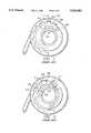
- FIG. 1a cross-sectional view of a rotatable grip actuating system for a derailleur gear shifting system on a bicycle showing a plastic detent spring in accordance with the prior art.
- FIG. 2is a cross-sectional view of a rotatable grip actuating system for a derailleur gear shifting system on a bicycle showing another embodiment of a plastic detent spring in accordance with the prior art.
- FIG. 3is an isometric view of a rotatable grip actuating system for a derailleur gear shifting system on a bicycle, in which a metal detent spring in accordance with this invention is employed.
- FIG. 4is an exploded isometric view of the rotatable grip actuating system shown in FIG. 3, incorporating a metal detent spring in accordance with a first embodiment of this invention.
- FIG. 5is a partial cross-sectional view taken along the line 5--5 in FIG. 3, showing the rotatable grip actuating system in accordance with the first embodiment of this invention in a first operative position.
- FIG. 6is a partial cross-sectional view taken along the line 6--6 in FIG. 3, showing the rotatable grip actuating system in accordance with the first embodiment of this invention in a second operative position.
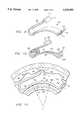
- FIG. 7is an isometric view of a detent spring in accordance with the first embodiment this invention.
- FIG. 8is an enlarged fragmentary cross-sectional view showing a second embodiment of the detent spring of this invention in a position similar to that shown in FIG. 5.
- FIG. 9is an isometric view of the second embodiment of the detent spring of this invention as shown in FIG. 8.
- FIG. 10is an isometric view of a third embodiment of the detent spring of this invention.
- FIG. 11is an enlarged fragmentary cross-sectional view showing a fourth embodiment of the detent spring of this invention in a position similar to that shown in FIG. 8.
- a rotatable grip actuating system 10is placed over a handlebar 12.
- the portion of the handlebar 14 shown projecting to the right in FIG. 3,is connected to the bicycle handlebar stem (not shown).
- the handlebar 12also projects to the left of the system 10 as shown in FIG. 3 to support the customary handgrip normally place at the end of the handlebar.
- the system 10has two principal components, a housing 16 secured to the handlebar 12 and a rotatable grip 18.
- the housing 16includes an elongated tube or mandrel 20 which is received in a snug fit over the handlebar 12.
- the housing 16is formed with a pocket (not shown) on the right side as viewed in FIG. 3 for receiving a U-shaped clamp 22 which secures the housing 16 to the handlebar 12.
- the clamp 22is secured to the handlebar by a bolt 24 which loosely passes through a hole 26 in one leg of the clamp and engages threads in a hole 28 provided in the other leg of the clamp.
- a cable guide tube 30Formed as a portion of the housing 16 is a cable guide tube 30.
- the guide tube 30is provided at its distal end with external threads 32 for mating with internal threads provided on a coupler 34.
- the coupler 34secures a cable tube 36 to the cable guide tube 30.
- a spring retaining portion 40Surrounding the mandrel 20, next to a radially extending wall 38 of the housing 16 is a spring retaining portion 40.
- a convex bend or detent 48 in the second portion of the springis engageable in notches 50, 52 and 54 formed on the inner generally cylindrical or circumferential surface of wall 56 of the rotatable grip 18.
- the interaction of the detent 48 of spring 46 with the notches 50, 52 and 54defines positions of the rotatable grip 18 with respect to the housing 16 which correspond to desired engagement positions of the derailleur shifting mechanism.
- the rotatable grip 18is formed with an external grip portion 58 and an adjoining enlarged portion 60 on which may be printed numerals, shown as 1, 2 and 3 in FIG. 1, which when located with respect to an index mark 62 on the housing 10 define three operating positions of the handgrip assembly. Extending to the left of the grip portion 58, as viewed in FIG. 4, is not only the wall 56, but also a cable retaining and engaging portion 64 of rotatable grip 18. An operating cable 66 is retained behind a radially extending wall portion 68 of portion 64 and a radial extending face 70 of the enlarged portion 60. The operating cable rests upon a spool 72 of variable radius formed between the wall portion 68 and the radially extending face 70.
- the radius at which rotation of the rotatable grip 18 acts on the operating cable 66is referred to as the spooling radius.
- a slot having a variable radial heightis formed between the wall portion 68 and radially extending face 70 to form the spool 72.
- the radial height of the slot at end 74 of the slotis just slightly larger than the diameter of the cable 66.
- a retainer 76is secured to the end of the cable to prevent it from being pulled through the slot.
- the spool 72having dropped away at 78, where the cable 66 exits from the slot, the radial height of the slot is considerably higher than the diameter of the cable. While the cable is shown engaging the radially outward surface of the slot in FIG. 4, when the system is assembled and tension applied to the cable, it rests on the radially inward surface or spool 72 as shown in FIGS. 5 and 6.
- the gripWith the cable 66 secured in the slot formed in the grip portion 18, and first portion of spring 44 placed in the elongated notch 42, the grip is assembled to the housing 16 in the directions of the arrow in FIG. 4 such that the wall 56 is received in a space 80 between an outer wall 82 of the housing 16 and the spring retaining portion 40.
- a cover 84is placed over the open portion of the cable guide tube 30 and secured in place by a screw 86 which is threadedly engaged in a hole 88 formed in a projection 90 extending from the housing 16.
- the detent spring assembly portion of the rotatable grip actuating systemincludes an inward facing generally cylindrical wall 56 in which are formed notches 50, 52 and 54.
- the number of notchescorresponds to the number of positions required for actuation of the derailleur shifting system.
- the stationary portion of the rotatable grip actuating systemincludes the mandrel 20 and a spring retaining member having an outwardly facing generally cylindrical surface in which is formed a spring retaining elongated notch 42.
- spring 46is formed with a first portion in the form of an elongated base member 44, the first and second ends 92 and 94 respectively of which are formed in a generally semicircular shape.
- First end or curve 92is curved at a radius r 2 around a center 93; second end or curve 94 is curved in a radius r 2 ' around a center 95.
- An arm or linear extension 96extends from the first end 92 of the spring 46 over the elongated base 44 to give the spring an overall narrow U-shape.
- the free end or straight extension 98 of the arm 96is bent by this third sharp bend 48 inwardly toward the first or base member 44.
- the base member 44 of the spring 46is curved at a radius r 1 from a center 99, which is located on the opposite side of spring 46 from centers 93 and 95. Secondary radii r 2 and r 2 ' are substantially smaller than first radius r 1 .
- radius r 1corresponds to the curvature of the base of the elongated notch 42.
- the ends or sidewalls 100 and 102 of elongated notch 42are spaced apart at a greater distance than the distance between the extremities of the curved portions 92 and 94 of the spring.
- the force required to move it in and out of one of the notches or detents 50, 52 or 54depends on the direction of rotation. Less force is required to rotate spring retaining portion 40, and therefore, the spring 46 in the direction of the arrow B, in FIG. 6, wherein sloping edge 104 of the detent 48 is engaged by the sloping portion of one of the notches 50, 52 or 54. That is, less force is required to depress the detent 48 and therefore the arm 96 as the detent 48 moves out of a notch.
- the spring 46offers greater resistance to rotation in the direction A as shown in FIG. 5.
- the engagement of the side of the detent 48 which continues as straight extension 98abuts a sloping edge of a notch 50, 52 or 54 to first apply a force through the arm 96 and the bend 92 to the end or sidewall 100 of the notch. While the detent 48 will eventually be depressed as it moves out of the notch or detent due to continued rotation of the spring retaining portion 40, a greater force is required to do so than for rotation in the direction of arrow B. With the spring 46 so formed, the notches 50, 52 and 54 can be made symmetrical while at the same time providing different degrees of resistance for rotation in opposite directions, thereby equalizing the force of the return spring in the derailleur shifting mechanism.
- the spring 46can be readily designed to operate within its elastic range at all times.
- the stiffness of the springcan be determined, for instance by varying the thickness of the spring leaf, a spring can be designed which will have a high contact force with the surface between notches when compressed, but a relatively low preload when residing in the notches 50, 52 and 54.
- the springmay be designed such that the rotatable grip 18 rotates freely in the cable release direction until the detent 48 of the spring meets the front wall of notches 50, 52 or 54, which is the desired cable position for a particular sprocket position.
- the curvature of the notch as it merges into the circumferential surface between the notchesmay have a larger radius, so as to cause less wear on both the detent 48 and the notches and the surfaces of the wall 56 engaged thereby.
- the torque required for rotating from one pre-determined position to anothercan in part be defined by the angle which the sides of the notches 50, 52 and 54 make with the radius of the wall 56 extending between the notches.
- the spring 106is similar to the spring 46 shown in FIG. 4-7, in that the first end of the spring 106 is curved and is provided with an arm 108. Further, a convex bend or detent 110 and extension 112 are formed at the free end of arm 108. The second end 114 of the spring 106 is formed with a radially extending portion 116.
- the spring retaining member 40is provided with a circumferentially extending portion or barrier 118 located radially outward and extending over the elongated notch 42 and the free end 120 of the radially extending portion 116 of the spring.
- the second end of the spring 114is prevented from lifting by the engagement of free end 120 with the barrier 118.
- the spring 46is formed of cylindrical wire.
- the force applied by the spring as it moves into and out of the notches 50, 52 and 54may be determined by selecting the characteristics of the spring wire including its diameter resilience, etc., and the formation of the spring, including the number of spirals of spring the length of the arm, etc.
- the springis formed from a single piece of cylindrical spring steel stock.
- the first end 130 of the springis formed as a pair of helixes.
- the inner end of each helixextends as an arm 132 at the ends of which is formed a generally rectangular portion 134.
- FIG. 11a further embodiment of a detent spring according to the invention is shown. This embodiment is similar to the one shown in FIGS. 8 and 9, and for that reason like characters identify like pans.
- a spring 106'is provided with a base 150 that has a radius of curvature r 4 that is smaller than the radius of curvature r n of the arcuate surface 152 of notch 42. Therefore, only the first curved end 154 and the second end 114 of spring 106' engage surface 152, with a middle portion 153 of base 150 being spaced from surface 152.
- FIG. 11also shows notches 50', 52' and 54' having sides which form different angles with respect to the surface of cylindrical wall 56. This is another method by which the notch engaging portion 110 may be made to experience less force when it travels over e.g. side 158, which forms a lesser slope with respect to the surface of wall 56 than opposed side 160.
Landscapes
- Engineering & Computer Science (AREA)
- Mechanical Engineering (AREA)
- Chemical & Material Sciences (AREA)
- Combustion & Propulsion (AREA)
- Transportation (AREA)
- Steering Devices For Bicycles And Motorcycles (AREA)
- Mechanical Control Devices (AREA)
- Gear-Shifting Mechanisms (AREA)
Abstract
Description
Claims (31)
Priority Applications (8)
| Application Number | Priority Date | Filing Date | Title |
|---|---|---|---|
| US08/295,370US5524501A (en) | 1994-03-07 | 1994-08-24 | Detent spring for rotatable grip actuating system |
| JP6341054AJPH0844450A (en) | 1994-03-07 | 1994-12-29 | Rotation-type grip operating device and its rotation stop mechanism |
| CN95101854ACN1111584A (en) | 1994-03-07 | 1995-02-25 | Detent spring for rotatable handgrip actuating system |
| DE69500508TDE69500508T2 (en) | 1994-03-07 | 1995-03-06 | Latch spring for rotary handle actuation device |
| EP95301444AEP0676325B1 (en) | 1994-03-07 | 1995-03-06 | Detent spring for rotatable handgrip actuating system |
| ES95301444TES2087053T3 (en) | 1994-03-07 | 1995-03-06 | ROTARY CONTROL OF SPEED CHANGE FOR HANDLEBAR MOUNTED BICYCLE. |
| DE0676325TDE676325T1 (en) | 1994-03-07 | 1995-03-06 | Latch spring for rotary handle actuation device. |
| US08/609,676US5662000A (en) | 1994-03-07 | 1996-03-01 | Detent spring for rotatable grip actuating system |
Applications Claiming Priority (2)
| Application Number | Priority Date | Filing Date | Title |
|---|---|---|---|
| US08/207,249US5476019A (en) | 1994-03-07 | 1994-03-07 | Rotatable handgrip actuating system |
| US08/295,370US5524501A (en) | 1994-03-07 | 1994-08-24 | Detent spring for rotatable grip actuating system |
Related Parent Applications (1)
| Application Number | Title | Priority Date | Filing Date |
|---|---|---|---|
| US08/207,249Continuation-In-PartUS5476019A (en) | 1994-03-07 | 1994-03-07 | Rotatable handgrip actuating system |
Related Child Applications (1)
| Application Number | Title | Priority Date | Filing Date |
|---|---|---|---|
| US08/609,676ContinuationUS5662000A (en) | 1994-03-07 | 1996-03-01 | Detent spring for rotatable grip actuating system |
Publications (1)
| Publication Number | Publication Date |
|---|---|
| US5524501Atrue US5524501A (en) | 1996-06-11 |
Family
ID=22769771
Family Applications (3)
| Application Number | Title | Priority Date | Filing Date |
|---|---|---|---|
| US08/207,249Expired - LifetimeUS5476019A (en) | 1994-03-07 | 1994-03-07 | Rotatable handgrip actuating system |
| US08/287,721Expired - LifetimeUS5584213A (en) | 1994-03-07 | 1994-08-09 | Rotatable grip for derailleur type bicycle gear shifting system |
| US08/295,370Expired - LifetimeUS5524501A (en) | 1994-03-07 | 1994-08-24 | Detent spring for rotatable grip actuating system |
Family Applications Before (2)
| Application Number | Title | Priority Date | Filing Date |
|---|---|---|---|
| US08/207,249Expired - LifetimeUS5476019A (en) | 1994-03-07 | 1994-03-07 | Rotatable handgrip actuating system |
| US08/287,721Expired - LifetimeUS5584213A (en) | 1994-03-07 | 1994-08-09 | Rotatable grip for derailleur type bicycle gear shifting system |
Country Status (5)
| Country | Link |
|---|---|
| US (3) | US5476019A (en) |
| EP (1) | EP0671318A3 (en) |
| JP (1) | JPH07259985A (en) |
| CN (1) | CN1111582A (en) |
| TW (2) | TW573662U (en) |
Cited By (41)
| Publication number | Priority date | Publication date | Assignee | Title |
|---|---|---|---|---|
| US5607367A (en)* | 1995-08-21 | 1997-03-04 | Sram Corporation | Linear derailleur |
| US5615580A (en)* | 1995-12-20 | 1997-04-01 | Chen; Fu H. | Bicycle gear selector mechanism |
| US5620383A (en)* | 1995-02-06 | 1997-04-15 | Sram Corporation | Bicycle derailleur and actuating system |
| US5622083A (en)* | 1996-02-02 | 1997-04-22 | Shimano Inc. | Gear shifting mechanism |
| US5676020A (en)* | 1995-06-30 | 1997-10-14 | Sram Corporation | Hand-rotatable bicycle gear shift actuator with overshift return |
| US5682963A (en)* | 1996-07-12 | 1997-11-04 | Tang; Jen-Hui | Brake assembly for a bicycle |
| US5784924A (en)* | 1997-03-25 | 1998-07-28 | Wu; Mu-Chuan | Gearshift adjusting device |
| US5921140A (en)* | 1996-04-04 | 1999-07-13 | Fichtel & Sachs Ag | Index shifter for a bicycle transmission and a method of making an index shifter for a bicycle transmission |
| US5988008A (en)* | 1997-08-11 | 1999-11-23 | Sram Deutschland Gmbh | Device for shifting bicycle gears |
| WO1999064290A1 (en)* | 1998-06-12 | 1999-12-16 | Ritchey Designs, Inc. | Handlebar-mounted bicycle shifter system and method |
| US6021688A (en)* | 1998-09-25 | 2000-02-08 | Chang; Wen-Pin | Twist handlebar for controlling the derailleur of a bicyle |
| US6042133A (en)* | 1997-01-14 | 2000-03-28 | Mannesmann Sachs Ag | Index shifter for bicycle transmissions |
| USD422194S (en) | 1998-06-22 | 2000-04-04 | Speed Control, Inc. | Shift mechanism |
| AT406365B (en)* | 1997-02-21 | 2000-04-25 | Josef Prajczer | BICYCLE GEAR |
| US6145407A (en)* | 1997-08-11 | 2000-11-14 | Sram Deutschland Gmbh | Click-stop gear shift for bicycles |
| US6367347B1 (en)* | 1998-08-04 | 2002-04-09 | Sram Deutschland Gmbh | Switch for bicycle speed-changing gear |
| US6484604B1 (en)* | 2001-06-05 | 2002-11-26 | Chi-Hsyan Feng | Easy cord-passing structure of shift handle of a bicycle |
| US6520489B1 (en) | 2001-03-29 | 2003-02-18 | Zama Japan | Throttle control for hand-held blowers |
| US6595894B2 (en) | 2001-03-09 | 2003-07-22 | Shimano (Singapore) Private Limited | Shift control device |
| US6604440B2 (en)* | 2000-09-05 | 2003-08-12 | Sram Deutschland Gmbh | Switch for a bicycle |
| US20030221506A1 (en)* | 2002-06-04 | 2003-12-04 | Wesling Kevin F. | Bicycle gear shifter having separate shift control members for cable pull and release |
| US20040069089A1 (en)* | 2002-10-15 | 2004-04-15 | Po-Cheng Chen | Handle mounted bicycles derailleur controller |
| US20050034904A1 (en)* | 1999-02-05 | 2005-02-17 | Huntsberger Kurt J. | Children's ride-on vehicle |
| EP1762484A2 (en) | 2005-09-07 | 2007-03-14 | Shimano Inc. | Bicycle shift control mechanism |
| CN1323894C (en)* | 2003-06-25 | 2007-07-04 | 日驰企业股份有限公司 | double pawl transmission |
| US20070214908A1 (en)* | 2006-03-15 | 2007-09-20 | Sram Deustchland Gmbh | Bicycle Shifter |
| US20080221389A1 (en)* | 2007-03-09 | 2008-09-11 | Beckman Andrew T | Hand assisted laparoscopic seal assembly with deflection feature |
| US20110203404A1 (en)* | 2010-02-25 | 2011-08-25 | Po-Cheng Chen | Bicycle Shifter |
| US20130137541A1 (en)* | 2011-01-28 | 2013-05-30 | Paha Designs, Llc | Gear transmission and derrailleur system |
| US20140024899A1 (en)* | 2012-07-19 | 2014-01-23 | Covidien Lp | Method and structure for selectively locking portions of a seal assembly |
| US20140155206A1 (en)* | 2011-01-28 | 2014-06-05 | Paha Designs, Llc | Gear transmission and derailleur system |
| US20140260752A1 (en)* | 2013-03-15 | 2014-09-18 | Rti Sports Vertrieb Von Sportartikeln Gmbh | Bicycle handle system |
| US20160318582A1 (en)* | 2011-01-28 | 2016-11-03 | Paha Designs, Llc | Gear transmission and derailleur system |
| US10022149B2 (en) | 2012-09-28 | 2018-07-17 | Covidien Lp | Optical trocar visualization system and apparatus |
| US11357542B2 (en) | 2019-06-21 | 2022-06-14 | Covidien Lp | Valve assembly and retainer for surgical access assembly |
| US11446058B2 (en) | 2020-03-27 | 2022-09-20 | Covidien Lp | Fixture device for folding a seal member |
| US11541218B2 (en) | 2020-03-20 | 2023-01-03 | Covidien Lp | Seal assembly for a surgical access assembly and method of manufacturing the same |
| US11642153B2 (en) | 2020-03-19 | 2023-05-09 | Covidien Lp | Instrument seal for surgical access assembly |
| US11717321B2 (en) | 2020-04-24 | 2023-08-08 | Covidien Lp | Access assembly with retention mechanism |
| US11717003B2 (en) | 2020-10-10 | 2023-08-08 | Nanjing Agricultural University | Grilling method for controlling content of polycyclic aromatic hydrocarbons in charcoal-grilled meat |
| US11812991B2 (en) | 2019-10-18 | 2023-11-14 | Covidien Lp | Seal assemblies for surgical access assemblies |
Families Citing this family (65)
| Publication number | Priority date | Publication date | Assignee | Title |
|---|---|---|---|---|
| US5477746A (en)* | 1994-03-21 | 1995-12-26 | Dura Automotive Systems, Inc. | Parking brake lever mechanism with lobe motion amplifying means |
| US5666859A (en)* | 1994-12-02 | 1997-09-16 | Fichtel & Sachs Ag | Latching shifter for a bicycle transmission |
| ATE252482T1 (en)* | 1995-02-15 | 2003-11-15 | Shimano Kk | METHOD FOR DETERMINING THE GEAR RATIO AND CORRESPONDING DEVICE FOR SHIFTING A BICYCLE CHAIN GEARS |
| EP0759393B1 (en)* | 1995-03-13 | 2002-08-21 | Sakae Co., Ltd. | Bicycle and speed change operating device for the same |
| US5632226A (en)* | 1995-09-27 | 1997-05-27 | Industrial Technology Resarch Institute | Bicycle speed indicator |
| US5678455A (en)* | 1996-02-15 | 1997-10-21 | Shimano, Inc. | Bar-end shifting device |
| CN1070134C (en)* | 1996-02-29 | 2001-08-29 | 株式会社岛野 | Univaxial composite bicycle control unit |
| US5706800A (en) | 1997-01-29 | 1998-01-13 | Cronk; Peter J. | Medicated nasal dilator |
| WO1998037340A1 (en)* | 1997-02-20 | 1998-08-27 | Sram Corporation | Discontinuous mechanical advantage front shifting for bicycles |
| US5802927A (en)* | 1997-03-12 | 1998-09-08 | Yu; Yung-Jung | Rotary driving mechanism for brake device |
| US6035742A (en)* | 1997-06-16 | 2000-03-14 | Valcor Concept Marketing, Inc. | Handlebar grip assembly |
| US6276227B1 (en)* | 1997-07-24 | 2001-08-21 | Shimano, Inc. | Bicycle shift control device |
| US6101895A (en)* | 1997-07-25 | 2000-08-15 | Shimano, Inc. | Grip for a bicycle shift control device |
| WO1999006268A1 (en)* | 1997-08-01 | 1999-02-11 | Helical Dynamics International Inc. | Rotatable handgrip controller |
| DE19753901A1 (en)* | 1997-12-05 | 1999-06-10 | Sram De Gmbh | Selector for gear of bicycle |
| US6484603B2 (en)* | 1997-12-05 | 2002-11-26 | Sram Deutschland Gmbh | Selector for a bicycle gear mechanism |
| US6098490A (en)* | 1997-12-05 | 2000-08-08 | General Motors Corporation | Universal actuator assembly |
| US6332373B1 (en) | 1999-02-16 | 2001-12-25 | Shimano Inc. | Gear indicator holder for a bicycle |
| US6389925B1 (en) | 1999-02-16 | 2002-05-21 | Shimano Inc. | Shift operating device |
| US6295888B1 (en) | 1999-02-16 | 2001-10-02 | Shimano Inc. | Gear indicator for a bicycle |
| US6389920B1 (en)* | 1999-03-09 | 2002-05-21 | AD II Engineering Inc. | Mechanism for easy and precise control of gear shifting device of bicycle |
| DE19922328A1 (en)* | 1999-05-14 | 2000-11-16 | Sram De Gmbh | Cable guide unit in switch for bicycle transmission, in which casing part has web with guide edge forming cable channel with cable guide |
| US6389929B1 (en)* | 1999-05-20 | 2002-05-21 | Sram Corporation | Elongated rotatable handgrip |
| US6343524B1 (en)* | 2000-01-07 | 2002-02-05 | Kuo-Cheng Lien | Bicycle rear derailleur shifting controller |
| EP1255669B1 (en) | 2000-02-08 | 2005-11-23 | L.H. Thomson Company Inc. | Bicycle rider hand attachment and cooperating gear shift actuator and associated methods |
| US6652941B1 (en)* | 2000-09-27 | 2003-11-25 | Bic Corporation | Grip element and method of manufacture thereof |
| TW470028U (en)* | 2000-12-27 | 2001-12-21 | Bo-Cheng Chen | Speed change handlebars grip of bicycle |
| US6571726B2 (en)* | 2001-04-27 | 2003-06-03 | Sunrace Roots Enterprise Co., Ltd. | Device for monitoring gear lever position |
| DE10132000A1 (en)* | 2001-07-02 | 2003-01-16 | Sram De Gmbh | Actuator housing |
| US7703179B2 (en)* | 2001-11-09 | 2010-04-27 | 3M Innovative Properties Company | Microreplicated surface |
| US6718844B2 (en)* | 2002-02-13 | 2004-04-13 | Shimano, Inc. | Twist-grip shift control device for a bicycle |
| US20030230160A1 (en)* | 2002-03-20 | 2003-12-18 | Ritchey Designs, Inc. | Barend mounted twist shifter with integrated brake actuator for bicycle |
| US7150205B2 (en) | 2002-04-04 | 2006-12-19 | Shimano, Inc. | Handgrip shifter for a bicycle |
| DE10216168A1 (en)* | 2002-04-12 | 2003-10-23 | Sram De Gmbh | Childs bicycle twist grip comprises cable reel of small diameter at handlebar end with cable guide curving to center and integral to curved hand guard. |
| GB0226538D0 (en)* | 2002-11-14 | 2002-12-18 | Renthal Ltd | Tapered grip for motorcycle handlebar |
| US20040168538A1 (en)* | 2003-02-28 | 2004-09-02 | Shimano, Inc. | Twist grip for operating a bicycle transmission |
| US7325812B2 (en)* | 2003-05-14 | 2008-02-05 | Eastway Fair Company Limited | Grip assembly for clutch cap, front sleeve, rear sleeve and method of making |
| US7104154B2 (en)* | 2003-05-29 | 2006-09-12 | Shimano Inc. | Bicycle shift control device |
| US7013751B2 (en)* | 2003-05-29 | 2006-03-21 | Shimano Inc. | Bicycle shift control device |
| TWM243593U (en)* | 2003-06-27 | 2004-09-11 | Bing-He Feng | Gearshift controlling apparatus for bicycle |
| US20060000304A1 (en)* | 2004-06-17 | 2006-01-05 | Deere & Company, A Delaware Corporation | Control lever with partially enclosed rotary wheel |
| DE102004014888A1 (en)* | 2004-03-26 | 2005-10-20 | Bayerische Motoren Werke Ag | operating element |
| JP2007076545A (en)* | 2005-09-15 | 2007-03-29 | Shimano Inc | Bicycle speed change device |
| CN102221073B (en) | 2005-12-09 | 2013-03-27 | 福博科技术公司 | Continuously variable transmission |
| EP1811202A1 (en) | 2005-12-30 | 2007-07-25 | Fallbrook Technologies, Inc. | A continuously variable gear transmission |
| US7882762B2 (en) | 2006-01-30 | 2011-02-08 | Fallbrook Technologies Inc. | System for manipulating a continuously variable transmission |
| WO2007106874A2 (en) | 2006-03-14 | 2007-09-20 | Autocraft Industries, Inc. | Improved wheelchair |
| JP4191757B2 (en)* | 2006-10-12 | 2008-12-03 | 株式会社シマノ | Bicycle shift control device |
| US20080284126A1 (en)* | 2007-05-16 | 2008-11-20 | Smith Stephen T | Adaptive brake and shift mechanism for a bicycle |
| CN103939602B (en) | 2007-11-16 | 2016-12-07 | 福博科知识产权有限责任公司 | Controllers for variable speed drives |
| US8690154B2 (en)* | 2009-06-27 | 2014-04-08 | Greg John Owoc | Safe and novel, lightweight hand-grip systems for manually spinning gaming wheels |
| US8403800B2 (en) | 2010-07-28 | 2013-03-26 | The Gates Corporation | Shift mechanism for a planetary gear transmission |
| US8596638B2 (en)* | 2011-02-08 | 2013-12-03 | Greg John Owoc | Rotatable hand grip system |
| US20120247252A1 (en)* | 2011-03-30 | 2012-10-04 | Wei-Hsuan Chang | Enclosing shift control device for a bicycle transmission |
| US20120247253A1 (en)* | 2011-04-01 | 2012-10-04 | Wei-Hsuan Chang | Shift control machine for a bicycle trasmission |
| US8955862B1 (en) | 2012-05-15 | 2015-02-17 | MonoMano, Inc. | Cycling control system |
| NZ737589A (en)* | 2015-06-24 | 2023-03-31 | Fisher & Paykel Healthcare Ltd | Breathing assistance apparatus |
| US10799076B2 (en)* | 2015-11-25 | 2020-10-13 | Simply Innovative LLC | Devices for preventing towel slippage |
| US10047861B2 (en) | 2016-01-15 | 2018-08-14 | Fallbrook Intellectual Property Company Llc | Systems and methods for controlling rollback in continuously variable transmissions |
| US10023266B2 (en) | 2016-05-11 | 2018-07-17 | Fallbrook Intellectual Property Company Llc | Systems and methods for automatic configuration and automatic calibration of continuously variable transmissions and bicycles having continuously variable transmissions |
| US10499559B2 (en)* | 2016-12-15 | 2019-12-10 | Home Depot Product Authority, Llc | Handle mounted control system for a broadcast spreader |
| US10689059B2 (en) | 2018-04-11 | 2020-06-23 | Sram, Llc | Control devices for operating bicycle components |
| US11215268B2 (en) | 2018-11-06 | 2022-01-04 | Fallbrook Intellectual Property Company Llc | Continuously variable transmissions, synchronous shifting, twin countershafts and methods for control of same |
| WO2020176392A1 (en) | 2019-02-26 | 2020-09-03 | Fallbrook Intellectual Property Company Llc | Reversible variable drives and systems and methods for control in forward and reverse directions |
| TWI842440B (en)* | 2023-03-17 | 2024-05-11 | 台灣微轉股份有限公司 | Shifter handle |
Citations (38)
| Publication number | Priority date | Publication date | Assignee | Title |
|---|---|---|---|---|
| US1231055A (en)* | 1917-01-18 | 1917-06-26 | Raymond P Packard | Controlling mechanism. |
| US2153430A (en)* | 1937-11-20 | 1939-04-04 | Mallory & Co Inc P R | Switch index mechanism |
| US2626335A (en)* | 1950-10-18 | 1953-01-20 | Hart Mfg Co | Electric switch |
| US3020778A (en)* | 1954-08-05 | 1962-02-13 | Frithjof C Davidson | Bicycle gear shift control |
| US3218879A (en)* | 1961-12-02 | 1965-11-23 | Raleigh Industries Ltd | Twist grip controls |
| US3489029A (en)* | 1967-03-17 | 1970-01-13 | Oak Electro Netics Corp | Detent spring |
| US3522745A (en)* | 1967-06-22 | 1970-08-04 | Tomos Motor Vehicles Factory | Gas control turning grip for motors with internal combustion |
| FR2146200A3 (en)* | 1971-07-21 | 1973-03-02 | Karlsruhe Augsburg Iweka | Take-up service - for simultaneously packaging textile strands on separate packages |
| FR2210973A5 (en)* | 1972-12-20 | 1974-07-12 | Juy Lucien | |
| US4055093A (en)* | 1976-06-18 | 1977-10-25 | Amf Incorporated | 10-Speed bicycles |
| GB2024381A (en)* | 1978-06-15 | 1980-01-09 | Ti Raleigh Ind Ltd | Twist grip controls |
| US4191065A (en)* | 1978-02-07 | 1980-03-04 | Beugelsdyk Anthony F | Throttle twist grip |
| US4201095A (en)* | 1975-08-25 | 1980-05-06 | Jack Myles | Semi-automatic gearshift for dual derailleur bicycle |
| US4267744A (en)* | 1978-03-03 | 1981-05-19 | Maeda Industries, Ltd. | Bicycle speed change lever |
| US4384864A (en)* | 1979-01-12 | 1983-05-24 | Agence Nationale De Valorisation De La Recherche (Anvar) | Selector for a bicycle derailleur and derailleur equipped with such a device |
| DE3317382A1 (en)* | 1983-05-13 | 1984-11-15 | Bayerische Motoren Werke AG, 8000 München | Bowden-cable sheath having, in at least one end section, two screwed parts rotatable relative to the sheath |
| US4526056A (en)* | 1981-09-19 | 1985-07-02 | Honda Giken Kogyo Kabushiki Kaisha | Choke lever device for a two-wheeled motor vehicle |
| US4548092A (en)* | 1983-02-10 | 1985-10-22 | Strong Jr Samuel Z | Bicycle gear shift unit |
| CH667244A5 (en)* | 1985-08-29 | 1988-09-30 | Pefag Ag | Twist-grip gearchange for bicycle - has clamp for Bowden cable and ratchet location of gears |
| EP0294720A2 (en)* | 1987-06-11 | 1988-12-14 | Hans-Peter Dr. Unseld | Turning handle for brake and gear-change |
| US4900291A (en)* | 1988-01-06 | 1990-02-13 | Sram Corporation | Bicycle gear shifting method and apparatus |
| US4938733A (en)* | 1988-01-06 | 1990-07-03 | Sram Corporation | Bicycle gear shifting method and apparatus |
| DE3938454A1 (en)* | 1989-11-18 | 1991-05-23 | Dietrich Gerhard Ellsaesser | Electrohydraulic gearchange for bicycle - with hydraulic commands directed to slave cylinder via electric valves |
| US5102372A (en)* | 1991-03-20 | 1992-04-07 | Sram Corporation | Bicycle derailleur cable actuating system |
| FR2657062B1 (en)* | 1990-01-12 | 1992-04-30 | Sachs Ind Sa | INDEXING CONTROL DEVICE FOR CYCLE DERAILLEUR. |
| WO1992010488A1 (en)* | 1990-12-14 | 1992-06-25 | Basf Aktiengesellschaft | Method of preparing formyltetrahydropyrans |
| US5134897A (en)* | 1989-10-20 | 1992-08-04 | Campagnolo S.R.L. | Twist-grip device for operating the gears of a bicycle |
| EP0523257A1 (en)* | 1991-02-13 | 1993-01-20 | Mory Suntour Inc. | Device for making gear change of bicycle |
| JPH0532191A (en)* | 1990-12-18 | 1993-02-09 | Bridgestone Cycle Co | Bicycle grip type gear shift operation device |
| US5186071A (en)* | 1990-03-09 | 1993-02-16 | Maeda Industries, Ltd. | Bicycle speed change lever assembly |
| EP0529664A2 (en)* | 1991-08-30 | 1993-03-03 | Fichtel & Sachs AG | A speed change system for a bicycle or the like |
| US5197927A (en)* | 1991-03-20 | 1993-03-30 | Sram Corporation | Bicycle derailleur cable actuating system |
| US5241877A (en)* | 1992-12-04 | 1993-09-07 | Chen Chun Hsung | Gear selector |
| EP0566024A1 (en)* | 1992-04-13 | 1993-10-20 | Fichtel & Sachs AG | Electrical adjusting device |
| EP0566025A1 (en)* | 1992-04-13 | 1993-10-20 | Fichtel & Sachs AG | Control device for an actuator |
| US5261858A (en)* | 1992-06-19 | 1993-11-16 | Browning Automatic Transmission | Method and system for computer-controlled bicycle gear shifting |
| WO1994002348A1 (en)* | 1992-07-28 | 1994-02-03 | Maeda Industries, Ltd. | Change gear operation device for bicycle |
| EP0585473A1 (en)* | 1992-03-23 | 1994-03-09 | Maeda Industries, Ltd. | Gear shifter for bicycle |
Family Cites Families (26)
| Publication number | Priority date | Publication date | Assignee | Title |
|---|---|---|---|---|
| GB189419602A (en)* | 1894-10-15 | 1894-11-17 | Charles Davies Vaughan | A New or Improved Apparatus for Stopping and Starting Road Vehicles. |
| GB122270A (en)* | 1918-01-26 | 1919-01-23 | John James Selby Walker | Improvements in Cork Hand-grip Attachment for Fishing Rods, Shafts of Golf Clubs, similar Manually Wielded Appliances, Handles of Cycles and the like. |
| DE688541C (en)* | 1937-12-18 | 1940-02-23 | Dr Hermann Tschebull | Handle adapted to the inner surface of the hand furn |
| CH261795A (en)* | 1946-03-16 | 1949-05-31 | Zuccotti Andrea | Motorcycle handlebars. |
| US3362238A (en)* | 1965-03-29 | 1968-01-09 | Shimano Industrial Co | Speed change gear mechanism for a bicycle |
| US3713350A (en)* | 1971-05-17 | 1973-01-30 | Schwinn Bicycle Co | Air cushion handlebar grip |
| JPS5227043B2 (en)* | 1971-08-24 | 1977-07-18 | ||
| JPS5846693B2 (en)* | 1975-11-28 | 1983-10-18 | 株式会社日立製作所 | Ondo sensor |
| US4308762A (en)* | 1980-04-14 | 1982-01-05 | Oakley, Inc. | Lightened hand grip |
| DE3631481A1 (en)* | 1986-09-16 | 1988-05-05 | Villiger Soehne Ag | ELECTROMECHANICAL BICYCLE GEAR |
| US5145210A (en)* | 1987-01-09 | 1992-09-08 | Lennon Dan C | Bicycle, handlebar and adapter system |
| US4941232A (en)* | 1987-10-07 | 1990-07-17 | Bettcher Industries, Inc. | Slip resistant, cushioning cover for handles |
| US5097566A (en)* | 1987-10-07 | 1992-03-24 | Bettcher Industries, Inc. | Slip-resistant cushioning covers for handles |
| US5134008A (en)* | 1988-04-07 | 1992-07-28 | Scanalma Ab | Covers for handles and the like |
| JPH073192Y2 (en)* | 1988-08-30 | 1995-01-30 | 株式会社エム・ジー・シー | Barrel structure of toy gun |
| USD319770S (en) | 1988-11-03 | 1991-09-10 | 3T S.P.A. | Set of grips for a bicycle handle bar |
| US4895044A (en)* | 1989-02-22 | 1990-01-23 | Aero Toys, Incorporated | Hand grip for cycle handles |
| JPH0337454A (en)* | 1989-06-29 | 1991-02-18 | Nakagawa Electric Ind Co Ltd | Geared motor |
| US5059158A (en)* | 1990-05-08 | 1991-10-22 | E.B.T., Inc. | Electronic transmission control system for a bicycle |
| US5224397A (en)* | 1990-09-25 | 1993-07-06 | Yoo Tae W | Finger pressure apparatus for a steering wheel cover |
| US5125286A (en)* | 1991-02-19 | 1992-06-30 | Ken Wilson | Handlebar handgrip |
| JPH04125996U (en)* | 1991-05-01 | 1992-11-17 | マエダ工業株式会社 | Bicycle gear shift lever device |
| IT1252263B (en)* | 1991-11-18 | 1995-06-08 | Catene Calibrate Regina | ELECTROMECHANICAL GEARBOX FOR BICYCLE |
| US5287767A (en)* | 1992-08-25 | 1994-02-22 | Classic Accessories, Inc. | Vehicle steering wheel cover |
| DE9317875U1 (en)* | 1993-11-23 | 1994-01-27 | Wu, Otto, Taipeh/T'ai-pei | Handle device |
| USD361695S (en) | 1994-05-31 | 1995-08-29 | Atico International, Inc. | Kitchen utensil handle |
- 1994
- 1994-03-07USUS08/207,249patent/US5476019A/ennot_activeExpired - Lifetime
- 1994-03-31TWTW91206847Upatent/TW573662U/ennot_activeIP Right Cessation
- 1994-03-31TWTW083102834Apatent/TW353054B/enactive
- 1994-08-09USUS08/287,721patent/US5584213A/ennot_activeExpired - Lifetime
- 1994-08-24USUS08/295,370patent/US5524501A/ennot_activeExpired - Lifetime
- 1995
- 1995-02-10JPJP7022441Apatent/JPH07259985A/enactivePending
- 1995-02-28CNCN95100443Apatent/CN1111582A/enactivePending
- 1995-03-06EPEP95301447Apatent/EP0671318A3/ennot_activeWithdrawn
Patent Citations (41)
| Publication number | Priority date | Publication date | Assignee | Title |
|---|---|---|---|---|
| US1231055A (en)* | 1917-01-18 | 1917-06-26 | Raymond P Packard | Controlling mechanism. |
| US2153430A (en)* | 1937-11-20 | 1939-04-04 | Mallory & Co Inc P R | Switch index mechanism |
| US2626335A (en)* | 1950-10-18 | 1953-01-20 | Hart Mfg Co | Electric switch |
| US3020778A (en)* | 1954-08-05 | 1962-02-13 | Frithjof C Davidson | Bicycle gear shift control |
| US3218879A (en)* | 1961-12-02 | 1965-11-23 | Raleigh Industries Ltd | Twist grip controls |
| US3489029A (en)* | 1967-03-17 | 1970-01-13 | Oak Electro Netics Corp | Detent spring |
| US3522745A (en)* | 1967-06-22 | 1970-08-04 | Tomos Motor Vehicles Factory | Gas control turning grip for motors with internal combustion |
| FR2146200A3 (en)* | 1971-07-21 | 1973-03-02 | Karlsruhe Augsburg Iweka | Take-up service - for simultaneously packaging textile strands on separate packages |
| FR2210973A5 (en)* | 1972-12-20 | 1974-07-12 | Juy Lucien | |
| US4201095A (en)* | 1975-08-25 | 1980-05-06 | Jack Myles | Semi-automatic gearshift for dual derailleur bicycle |
| US4055093A (en)* | 1976-06-18 | 1977-10-25 | Amf Incorporated | 10-Speed bicycles |
| US4191065A (en)* | 1978-02-07 | 1980-03-04 | Beugelsdyk Anthony F | Throttle twist grip |
| US4267744A (en)* | 1978-03-03 | 1981-05-19 | Maeda Industries, Ltd. | Bicycle speed change lever |
| GB2024381A (en)* | 1978-06-15 | 1980-01-09 | Ti Raleigh Ind Ltd | Twist grip controls |
| US4384864A (en)* | 1979-01-12 | 1983-05-24 | Agence Nationale De Valorisation De La Recherche (Anvar) | Selector for a bicycle derailleur and derailleur equipped with such a device |
| US4526056A (en)* | 1981-09-19 | 1985-07-02 | Honda Giken Kogyo Kabushiki Kaisha | Choke lever device for a two-wheeled motor vehicle |
| US4619154A (en)* | 1981-09-19 | 1986-10-28 | Honda Giken Kogyo K.K. | Choke lever device for a motor vehicle |
| US4548092A (en)* | 1983-02-10 | 1985-10-22 | Strong Jr Samuel Z | Bicycle gear shift unit |
| DE3317382A1 (en)* | 1983-05-13 | 1984-11-15 | Bayerische Motoren Werke AG, 8000 München | Bowden-cable sheath having, in at least one end section, two screwed parts rotatable relative to the sheath |
| CH667244A5 (en)* | 1985-08-29 | 1988-09-30 | Pefag Ag | Twist-grip gearchange for bicycle - has clamp for Bowden cable and ratchet location of gears |
| EP0294720A2 (en)* | 1987-06-11 | 1988-12-14 | Hans-Peter Dr. Unseld | Turning handle for brake and gear-change |
| US4938733A (en)* | 1988-01-06 | 1990-07-03 | Sram Corporation | Bicycle gear shifting method and apparatus |
| US4900291A (en)* | 1988-01-06 | 1990-02-13 | Sram Corporation | Bicycle gear shifting method and apparatus |
| US4900291B1 (en)* | 1988-01-06 | 2000-04-25 | Sram Corp | Bicycle gear shifting method and apparatus |
| US5134897A (en)* | 1989-10-20 | 1992-08-04 | Campagnolo S.R.L. | Twist-grip device for operating the gears of a bicycle |
| DE3938454A1 (en)* | 1989-11-18 | 1991-05-23 | Dietrich Gerhard Ellsaesser | Electrohydraulic gearchange for bicycle - with hydraulic commands directed to slave cylinder via electric valves |
| FR2657062B1 (en)* | 1990-01-12 | 1992-04-30 | Sachs Ind Sa | INDEXING CONTROL DEVICE FOR CYCLE DERAILLEUR. |
| US5186071A (en)* | 1990-03-09 | 1993-02-16 | Maeda Industries, Ltd. | Bicycle speed change lever assembly |
| WO1992010488A1 (en)* | 1990-12-14 | 1992-06-25 | Basf Aktiengesellschaft | Method of preparing formyltetrahydropyrans |
| JPH0532191A (en)* | 1990-12-18 | 1993-02-09 | Bridgestone Cycle Co | Bicycle grip type gear shift operation device |
| EP0523257A1 (en)* | 1991-02-13 | 1993-01-20 | Mory Suntour Inc. | Device for making gear change of bicycle |
| US5102372A (en)* | 1991-03-20 | 1992-04-07 | Sram Corporation | Bicycle derailleur cable actuating system |
| US5197927A (en)* | 1991-03-20 | 1993-03-30 | Sram Corporation | Bicycle derailleur cable actuating system |
| US5197927B1 (en)* | 1991-03-20 | 2000-10-17 | Sram Corp | Bicycle derailleur cable actuating system |
| EP0529664A2 (en)* | 1991-08-30 | 1993-03-03 | Fichtel & Sachs AG | A speed change system for a bicycle or the like |
| EP0585473A1 (en)* | 1992-03-23 | 1994-03-09 | Maeda Industries, Ltd. | Gear shifter for bicycle |
| EP0566025A1 (en)* | 1992-04-13 | 1993-10-20 | Fichtel & Sachs AG | Control device for an actuator |
| EP0566024A1 (en)* | 1992-04-13 | 1993-10-20 | Fichtel & Sachs AG | Electrical adjusting device |
| US5261858A (en)* | 1992-06-19 | 1993-11-16 | Browning Automatic Transmission | Method and system for computer-controlled bicycle gear shifting |
| WO1994002348A1 (en)* | 1992-07-28 | 1994-02-03 | Maeda Industries, Ltd. | Change gear operation device for bicycle |
| US5241877A (en)* | 1992-12-04 | 1993-09-07 | Chen Chun Hsung | Gear selector |
Cited By (65)
| Publication number | Priority date | Publication date | Assignee | Title |
|---|---|---|---|---|
| US5620383A (en)* | 1995-02-06 | 1997-04-15 | Sram Corporation | Bicycle derailleur and actuating system |
| US5676020A (en)* | 1995-06-30 | 1997-10-14 | Sram Corporation | Hand-rotatable bicycle gear shift actuator with overshift return |
| US5607367A (en)* | 1995-08-21 | 1997-03-04 | Sram Corporation | Linear derailleur |
| US5615580A (en)* | 1995-12-20 | 1997-04-01 | Chen; Fu H. | Bicycle gear selector mechanism |
| US5622083A (en)* | 1996-02-02 | 1997-04-22 | Shimano Inc. | Gear shifting mechanism |
| US5921140A (en)* | 1996-04-04 | 1999-07-13 | Fichtel & Sachs Ag | Index shifter for a bicycle transmission and a method of making an index shifter for a bicycle transmission |
| US5682963A (en)* | 1996-07-12 | 1997-11-04 | Tang; Jen-Hui | Brake assembly for a bicycle |
| US6042133A (en)* | 1997-01-14 | 2000-03-28 | Mannesmann Sachs Ag | Index shifter for bicycle transmissions |
| AT406365B (en)* | 1997-02-21 | 2000-04-25 | Josef Prajczer | BICYCLE GEAR |
| US5784924A (en)* | 1997-03-25 | 1998-07-28 | Wu; Mu-Chuan | Gearshift adjusting device |
| US5988008A (en)* | 1997-08-11 | 1999-11-23 | Sram Deutschland Gmbh | Device for shifting bicycle gears |
| US6145407A (en)* | 1997-08-11 | 2000-11-14 | Sram Deutschland Gmbh | Click-stop gear shift for bicycles |
| WO1999064290A1 (en)* | 1998-06-12 | 1999-12-16 | Ritchey Designs, Inc. | Handlebar-mounted bicycle shifter system and method |
| US6067875A (en)* | 1998-06-12 | 2000-05-30 | Ritchey Designs, Inc. | Handlebar-mounted bicycle shifter system and method |
| USD422194S (en) | 1998-06-22 | 2000-04-04 | Speed Control, Inc. | Shift mechanism |
| US6367347B1 (en)* | 1998-08-04 | 2002-04-09 | Sram Deutschland Gmbh | Switch for bicycle speed-changing gear |
| US6021688A (en)* | 1998-09-25 | 2000-02-08 | Chang; Wen-Pin | Twist handlebar for controlling the derailleur of a bicyle |
| US7530411B2 (en) | 1999-02-05 | 2009-05-12 | Mattel, Inc. | Children's ride-on vehicle |
| US20070261900A1 (en)* | 1999-02-05 | 2007-11-15 | Huntsberger Kurt J | Children's ride-on vehicle |
| US8141668B2 (en) | 1999-02-05 | 2012-03-27 | Mattel, Inc. | Children's ride-on vehicle |
| US20050034904A1 (en)* | 1999-02-05 | 2005-02-17 | Huntsberger Kurt J. | Children's ride-on vehicle |
| US20050280217A1 (en)* | 1999-02-05 | 2005-12-22 | Huntsberger Kurt J | Children's ride-on vehicle |
| US6994179B2 (en)* | 1999-02-05 | 2006-02-07 | Mattel, Inc. | Children's ride-on vehicle |
| US6604440B2 (en)* | 2000-09-05 | 2003-08-12 | Sram Deutschland Gmbh | Switch for a bicycle |
| US6595894B2 (en) | 2001-03-09 | 2003-07-22 | Shimano (Singapore) Private Limited | Shift control device |
| US6520489B1 (en) | 2001-03-29 | 2003-02-18 | Zama Japan | Throttle control for hand-held blowers |
| US6484604B1 (en)* | 2001-06-05 | 2002-11-26 | Chi-Hsyan Feng | Easy cord-passing structure of shift handle of a bicycle |
| US6729203B2 (en)* | 2002-06-04 | 2004-05-04 | Sram Corporation | Bicycle gear shifter having separate shift control members for cable pull and release |
| US20030221506A1 (en)* | 2002-06-04 | 2003-12-04 | Wesling Kevin F. | Bicycle gear shifter having separate shift control members for cable pull and release |
| US20040069089A1 (en)* | 2002-10-15 | 2004-04-15 | Po-Cheng Chen | Handle mounted bicycles derailleur controller |
| CN1323894C (en)* | 2003-06-25 | 2007-07-04 | 日驰企业股份有限公司 | double pawl transmission |
| US20070068312A1 (en)* | 2005-09-07 | 2007-03-29 | Shimano Inc. | Bicycle shift control mechanism |
| EP1762484A2 (en) | 2005-09-07 | 2007-03-14 | Shimano Inc. | Bicycle shift control mechanism |
| US20070214908A1 (en)* | 2006-03-15 | 2007-09-20 | Sram Deustchland Gmbh | Bicycle Shifter |
| US7681472B2 (en)* | 2006-03-15 | 2010-03-23 | Sram, Llc | Bicycle shifter |
| US20080221389A1 (en)* | 2007-03-09 | 2008-09-11 | Beckman Andrew T | Hand assisted laparoscopic seal assembly with deflection feature |
| US8002786B2 (en)* | 2007-03-09 | 2011-08-23 | Ethicon Endo-Surgery, Inc. | Hand assisted laparoscopic seal assembly with deflection feature |
| US20110203404A1 (en)* | 2010-02-25 | 2011-08-25 | Po-Cheng Chen | Bicycle Shifter |
| US8220357B2 (en)* | 2010-02-25 | 2012-07-17 | Po-Cheng Chen | Bicycle shifter |
| US10207772B2 (en)* | 2011-01-28 | 2019-02-19 | Paha Designs, Llc | Gear transmission and derailleur system |
| US20140155206A1 (en)* | 2011-01-28 | 2014-06-05 | Paha Designs, Llc | Gear transmission and derailleur system |
| US9033833B2 (en)* | 2011-01-28 | 2015-05-19 | Paha Designs, Llc | Gear transmission and derailleur system |
| US9327792B2 (en)* | 2011-01-28 | 2016-05-03 | Paha Designs, Llc | Gear transmission and derailleur system |
| US20160318582A1 (en)* | 2011-01-28 | 2016-11-03 | Paha Designs, Llc | Gear transmission and derailleur system |
| US20130137541A1 (en)* | 2011-01-28 | 2013-05-30 | Paha Designs, Llc | Gear transmission and derrailleur system |
| US10111685B2 (en) | 2012-07-19 | 2018-10-30 | Covidien Lp | Method and structure for selectively locking portions of a seal assembly |
| US10772661B2 (en) | 2012-07-19 | 2020-09-15 | Covidien Lp | Method and structure for selectively locking portions of a seal assembly |
| US9247956B2 (en)* | 2012-07-19 | 2016-02-02 | Covidien Lp | Method and structure for selectively locking portions of a seal assembly |
| US20140024899A1 (en)* | 2012-07-19 | 2014-01-23 | Covidien Lp | Method and structure for selectively locking portions of a seal assembly |
| US9895164B2 (en) | 2012-07-19 | 2018-02-20 | Covidien Lp | Method and structure for selectively locking portions of a seal assembly |
| US10588662B2 (en) | 2012-09-28 | 2020-03-17 | Covidien Lp | Optical trocar visualization system and apparatus |
| US11529169B2 (en) | 2012-09-28 | 2022-12-20 | Covidien Lp | Optical trocar visualization system and apparatus |
| US10022149B2 (en) | 2012-09-28 | 2018-07-17 | Covidien Lp | Optical trocar visualization system and apparatus |
| US9490082B2 (en)* | 2013-03-15 | 2016-11-08 | Rti Sports Vertrieb Von Sportartikeln Gmbh | Bicycle handle system |
| US20140260752A1 (en)* | 2013-03-15 | 2014-09-18 | Rti Sports Vertrieb Von Sportartikeln Gmbh | Bicycle handle system |
| US11357542B2 (en) | 2019-06-21 | 2022-06-14 | Covidien Lp | Valve assembly and retainer for surgical access assembly |
| US12127762B2 (en) | 2019-06-21 | 2024-10-29 | Covidien, LP | Valve assembly and retainer for surgical access assembly |
| US11812991B2 (en) | 2019-10-18 | 2023-11-14 | Covidien Lp | Seal assemblies for surgical access assemblies |
| US11642153B2 (en) | 2020-03-19 | 2023-05-09 | Covidien Lp | Instrument seal for surgical access assembly |
| US12127763B2 (en) | 2020-03-19 | 2024-10-29 | Covidien Lp | Instrument seal for surgical access assembly |
| US11541218B2 (en) | 2020-03-20 | 2023-01-03 | Covidien Lp | Seal assembly for a surgical access assembly and method of manufacturing the same |
| US12064141B2 (en) | 2020-03-27 | 2024-08-20 | Covidien Lp | Fixture device for folding a seal member |
| US11446058B2 (en) | 2020-03-27 | 2022-09-20 | Covidien Lp | Fixture device for folding a seal member |
| US11717321B2 (en) | 2020-04-24 | 2023-08-08 | Covidien Lp | Access assembly with retention mechanism |
| US11717003B2 (en) | 2020-10-10 | 2023-08-08 | Nanjing Agricultural University | Grilling method for controlling content of polycyclic aromatic hydrocarbons in charcoal-grilled meat |
Also Published As
| Publication number | Publication date |
|---|---|
| EP0671318A3 (en) | 1996-02-07 |
| CN1111582A (en) | 1995-11-15 |
| EP0671318A2 (en) | 1995-09-13 |
| JPH07259985A (en) | 1995-10-13 |
| US5476019A (en) | 1995-12-19 |
| US5584213A (en) | 1996-12-17 |
| TW573662U (en) | 2004-01-21 |
| TW353054B (en) | 1999-02-21 |
Similar Documents
| Publication | Publication Date | Title |
|---|---|---|
| US5524501A (en) | Detent spring for rotatable grip actuating system | |
| US5662000A (en) | Detent spring for rotatable grip actuating system | |
| EP1553017B1 (en) | Switch style bicycle shift control device | |
| JP4402445B2 (en) | Watch case | |
| US5588925A (en) | Shifter for transmissions on bicycles | |
| EP2578487B1 (en) | Bicycle front derailleur with a variable actuation ratio | |
| EP0790175A1 (en) | Bicycle shift levers which surround a handlebar | |
| KR100676990B1 (en) | A ratchet device for electrical components that can be controlled by rotation | |
| US5321993A (en) | Transmission shift control apparatus | |
| EP1298362B1 (en) | Shift actuator for a transmission | |
| US5666859A (en) | Latching shifter for a bicycle transmission | |
| US5666858A (en) | Twist grip for actuating gears of a pedal cycle | |
| US20050126329A1 (en) | Shifter for a bicycle transmission | |
| US5144854A (en) | Transmission shift control reverse inhibitor apparatus | |
| TW201831372A (en) | Mechanical actuation device for actuating the control cable of a bicycle derailleur | |
| US5121650A (en) | Positioning shaft supported rotatably and axially in a casing | |
| US5988008A (en) | Device for shifting bicycle gears | |
| US20120192670A1 (en) | Operation device of shift mechanism in manual transmission | |
| US4739967A (en) | Mechanical detent | |
| KR100402077B1 (en) | Shift controlling system of manual transmission | |
| EP1549865B1 (en) | A shift lever mechanism | |
| US4269081A (en) | Neutral positioning device for a gear shift lever | |
| JPH05501531A (en) | A device that operates the control valve of a hydraulic power steering system | |
| KR100452599B1 (en) | The structure of control shaft assembly | |
| CN112728061B (en) | Noise-damping rotary shifter for a motor vehicle transmission |
Legal Events
| Date | Code | Title | Description |
|---|---|---|---|
| AS | Assignment | Owner name:SRAM CORPORATION, ILLINOIS Free format text:ASSIGNMENT OF ASSIGNORS INTEREST;ASSIGNORS:PATTERSON, SAM;CHEEVER, JOHN DAVID;LARSON, MICHAEL W.;AND OTHERS;REEL/FRAME:007131/0988 Effective date:19940816 | |
| FEPP | Fee payment procedure | Free format text:ENTITY STATUS SET TO SMALL (ORIGINAL EVENT CODE: SMAL); ENTITY STATUS OF PATENT OWNER: LARGE ENTITY | |
| STCF | Information on status: patent grant | Free format text:PATENTED CASE | |
| AS | Assignment | Owner name:LASALLE NATIONAL BANK, ILLINOIS Free format text:SECURITY INTEREST;ASSIGNOR:SRAM CORPORATION;REEL/FRAME:009360/0124 Effective date:19980707 | |
| FPAY | Fee payment | Year of fee payment:4 | |
| AS | Assignment | Owner name:BANK OF AMERICA, N.A., AS AGENT, A NATIONAL BANKIN Free format text:SECURITY AGREEMENT;ASSIGNOR:SRAM CORPORATION, A CORPORATION OF ILLINOIS;REEL/FRAME:011325/0409 Effective date:20001005 | |
| AS | Assignment | Owner name:BANK OF AMERICA, N.A., AS AGENT, ILLINOIS Free format text:CORRECTIVE ASSIGNMENT TO CORRECT THE RECEIVING PARTY'S ADDRESS, PREVIOUSLY RECORDED AT REEL 011325 FRAME 0409;ASSIGNOR:SRAM CORPORATION;REEL/FRAME:011828/0135 Effective date:20001005 | |
| FPAY | Fee payment | Year of fee payment:8 | |
| FEPP | Fee payment procedure | Free format text:PAT HOLDER NO LONGER CLAIMS SMALL ENTITY STATUS, ENTITY STATUS SET TO UNDISCOUNTED (ORIGINAL EVENT CODE: STOL); ENTITY STATUS OF PATENT OWNER: LARGE ENTITY | |
| AS | Assignment | Owner name:SRAM CORPORATION, ILLINOIS Free format text:INTELLECTUAL PROPERTY RELEASE;ASSIGNOR:LASALLE BANK, NATIONAL ASSOCIATION;REEL/FRAME:020105/0325 Effective date:20071105 | |
| AS | Assignment | Owner name:JPMORGAN CHASE BANK N.A., AS AGENT, ILLINOIS Free format text:SECURITY INTEREST;ASSIGNOR:SRAM CORPORATION;REEL/FRAME:020112/0544 Effective date:20071105 Owner name:JPMORGAN CHASE BANK N.A., AS AGENT,ILLINOIS Free format text:SECURITY INTEREST;ASSIGNOR:SRAM CORPORATION;REEL/FRAME:020112/0544 Effective date:20071105 | |
| FPAY | Fee payment | Year of fee payment:12 | |
| SULP | Surcharge for late payment | ||
| AS | Assignment | Owner name:SRAM CORPORATION, ILLINOIS Free format text:RELEASE BY SECURED PARTY;ASSIGNOR:JPMORGAN CHASE BANK, N.A., AS COLLATERAL AGENT;REEL/FRAME:021603/0759 Effective date:20080930 Owner name:SRAM, LLC, ILLINOIS Free format text:MERGER;ASSIGNOR:SRAM CORPORATION;REEL/FRAME:021617/0263 Effective date:20080930 Owner name:SRAM, LLC,ILLINOIS Free format text:MERGER;ASSIGNOR:SRAM CORPORATION;REEL/FRAME:021617/0263 Effective date:20080930 Owner name:SRAM CORPORATION,ILLINOIS Free format text:RELEASE BY SECURED PARTY;ASSIGNOR:JPMORGAN CHASE BANK, N.A., AS COLLATERAL AGENT;REEL/FRAME:021603/0759 Effective date:20080930 | |
| AS | Assignment | Owner name:GENERAL ELECTRIC CAPITAL CORPORATION, AS ADMINISTR Free format text:SECURITY AGREEMENT;ASSIGNOR:SRAM, LLC;REEL/FRAME:021630/0135 Effective date:20080930 | |
| AS | Assignment | Owner name:SRAM, LLC, ILLINOIS Free format text:RELEASE OF SECURITY INTEREST IN INTELLECTUAL PROPERTY COLLATERAL;ASSIGNOR:GENERAL ELECTRIC CAPITAL CORPORATION, AS ADMINISTRATIVE AGENT;REEL/FRAME:026533/0452 Effective date:20110607 | |
| AS | Assignment | Owner name:JPMORGAN CHASE BANK, N.A. AS ADMINISTRATIVE AGENT, Free format text:SECOND LIEN PATENT SECURITY AGREEMENT;ASSIGNORS:COMPOSITECH;SRAM LLC;REEL/FRAME:026869/0309 Effective date:20110607 Owner name:JPMORGAN CHASE BANK, N.A., AS ADMINISTRATIVE AGENT Free format text:FIRST LIEN PATENT SECURITY AGREEMENT;ASSIGNORS:COMPOSITECH;SRAM LLC;REEL/FRAME:026856/0464 Effective date:20110607 | |
| AS | Assignment | Owner name:SRAM, LLC, ILLINOIS Free format text:RELEASE BY SECURED PARTY;ASSIGNOR:JPMORGAN CHASE BANK, N.A., AS ADMINISTRATIVE AGENT;REEL/FRAME:030248/0914 Effective date:20130417 Owner name:COMPOSITECH, INC., ILLINOIS Free format text:RELEASE BY SECURED PARTY;ASSIGNOR:JPMORGAN CHASE BANK, N.A., AS ADMINISTRATIVE AGENT;REEL/FRAME:030248/0914 Effective date:20130417 |