US5522894A - Bone replacement material made of absorbable beads - Google Patents
Bone replacement material made of absorbable beadsDownload PDFInfo
- Publication number
- US5522894A US5522894AUS08/039,517US3951793AUS5522894AUS 5522894 AUS5522894 AUS 5522894AUS 3951793 AUS3951793 AUS 3951793AUS 5522894 AUS5522894 AUS 5522894A
- Authority
- US
- United States
- Prior art keywords
- bone
- replacement material
- elementary
- elementary bodies
- bone replacement
- Prior art date
- Legal status (The legal status is an assumption and is not a legal conclusion. Google has not performed a legal analysis and makes no representation as to the accuracy of the status listed.)
- Expired - Lifetime
Links
- 239000000316bone substituteSubstances0.000titleclaimsabstractdescription68
- 239000011324beadSubstances0.000titledescription25
- 238000000576coating methodMethods0.000claimsabstractdescription35
- 230000008093supporting effectEffects0.000claimsabstractdescription35
- 239000000126substanceSubstances0.000claimsabstractdescription34
- 238000004873anchoringMethods0.000claimsabstractdescription31
- 239000011248coating agentSubstances0.000claimsabstractdescription29
- 239000000463materialSubstances0.000claimsabstractdescription29
- 239000007943implantSubstances0.000claimsabstractdescription24
- 210000000988bone and boneAnatomy0.000claimsdescription121
- 238000000034methodMethods0.000claimsdescription16
- 102000008186CollagenHuman genes0.000claimsdescription14
- 108010035532CollagenProteins0.000claimsdescription14
- 229920001436collagenPolymers0.000claimsdescription14
- 230000037176bone buildingEffects0.000claimsdescription12
- 230000035515penetrationEffects0.000claimsdescription11
- QORWJWZARLRLPR-UHFFFAOYSA-Htricalcium bis(phosphate)Chemical compound[Ca+2].[Ca+2].[Ca+2].[O-]P([O-])([O-])=O.[O-]P([O-])([O-])=OQORWJWZARLRLPR-UHFFFAOYSA-H0.000claimsdescription11
- 239000001506calcium phosphateSubstances0.000claimsdescription10
- 235000019731tricalcium phosphateNutrition0.000claimsdescription10
- 229910052586apatiteInorganic materials0.000claimsdescription9
- VSIIXMUUUJUKCM-UHFFFAOYSA-Dpentacalcium;fluoride;triphosphateChemical compound[F-].[Ca+2].[Ca+2].[Ca+2].[Ca+2].[Ca+2].[O-]P([O-])([O-])=O.[O-]P([O-])([O-])=O.[O-]P([O-])([O-])=OVSIIXMUUUJUKCM-UHFFFAOYSA-D0.000claimsdescription9
- 229910000391tricalcium phosphateInorganic materials0.000claimsdescription9
- 229940078499tricalcium phosphateDrugs0.000claimsdescription9
- 229920001184polypeptidePolymers0.000claimsdescription5
- 102000004196processed proteins & peptidesHuman genes0.000claimsdescription5
- 108090000765processed proteins & peptidesProteins0.000claimsdescription5
- 239000003242anti bacterial agentSubstances0.000claimsdescription4
- 229940030225antihemorrhagicsDrugs0.000claimsdescription4
- 239000002874hemostatic agentSubstances0.000claimsdescription4
- 229940088597hormoneDrugs0.000claimsdescription4
- 239000005556hormoneSubstances0.000claimsdescription4
- 238000011282treatmentMethods0.000claimsdescription4
- SFLSHLFXELFNJZ-QMMMGPOBSA-N(-)-norepinephrineChemical compoundNC[C@H](O)C1=CC=C(O)C(O)=C1SFLSHLFXELFNJZ-QMMMGPOBSA-N0.000claimsdescription3
- 230000003115biocidal effectEffects0.000claimsdescription3
- 230000002227vasoactive effectEffects0.000claimsdescription3
- 102000055006CalcitoninHuman genes0.000claimsdescription2
- 108060001064CalcitoninProteins0.000claimsdescription2
- 229940088710antibiotic agentDrugs0.000claimsdescription2
- BBBFJLBPOGFECG-VJVYQDLKSA-NcalcitoninChemical compoundN([C@H](C(=O)N[C@@H](CC(C)C)C(=O)NCC(=O)N[C@@H](CCCCN)C(=O)N[C@@H](CC(C)C)C(=O)N[C@@H](CO)C(=O)N[C@@H](CCC(N)=O)C(=O)N[C@@H](CCC(O)=O)C(=O)N[C@@H](CC(C)C)C(=O)N[C@@H](CC=1NC=NC=1)C(=O)N[C@@H](CCCCN)C(=O)N[C@@H](CC(C)C)C(=O)N[C@@H](CCC(N)=O)C(=O)N[C@@H]([C@@H](C)O)C(=O)N[C@@H](CC=1C=CC(O)=CC=1)C(=O)N1[C@@H](CCC1)C(=O)N[C@@H](CCCNC(N)=N)C(=O)N[C@@H]([C@@H](C)O)C(=O)N[C@@H](CC(N)=O)C(=O)N[C@@H]([C@@H](C)O)C(=O)NCC(=O)N[C@@H](CO)C(=O)NCC(=O)N[C@@H]([C@@H](C)O)C(=O)N1[C@@H](CCC1)C(N)=O)C(C)C)C(=O)[C@@H]1CSSC[C@H](N)C(=O)N[C@@H](CO)C(=O)N[C@@H](CC(N)=O)C(=O)N[C@@H](CC(C)C)C(=O)N[C@@H](CO)C(=O)N[C@@H]([C@@H](C)O)C(=O)N1BBBFJLBPOGFECG-VJVYQDLKSA-N0.000claimsdescription2
- 229960004015calcitoninDrugs0.000claimsdescription2
- 206010031252OsteomyelitisDiseases0.000claims1
- 239000002550vasoactive agentSubstances0.000claims1
- 239000000945fillerSubstances0.000abstractdescription27
- 239000011159matrix materialSubstances0.000abstractdescription24
- 229940043430calcium compoundDrugs0.000abstractdescription6
- 150000001674calcium compoundsChemical class0.000abstractdescription6
- 239000011148porous materialSubstances0.000abstractdescription6
- 239000012798spherical particleSubstances0.000abstractdescription5
- 230000015572biosynthetic processEffects0.000description14
- 238000005755formation reactionMethods0.000description14
- 210000004027cellAnatomy0.000description11
- 229910052751metalInorganic materials0.000description11
- 239000002184metalSubstances0.000description11
- 210000000963osteoblastAnatomy0.000description11
- 239000000919ceramicSubstances0.000description8
- 230000011164ossificationEffects0.000description8
- 239000013543active substanceSubstances0.000description7
- 239000000203mixtureSubstances0.000description7
- 239000002245particleSubstances0.000description7
- 239000004033plasticSubstances0.000description7
- 229920003023plasticPolymers0.000description7
- 238000005266castingMethods0.000description6
- 238000013461designMethods0.000description6
- 239000000835fiberSubstances0.000description6
- 230000008569processEffects0.000description6
- 239000011230binding agentSubstances0.000description5
- 230000000877morphologic effectEffects0.000description5
- 241001465754MetazoaSpecies0.000description4
- 239000002639bone cementSubstances0.000description4
- 238000011049fillingMethods0.000description4
- 238000007493shaping processMethods0.000description4
- 239000001828GelatineSubstances0.000description3
- 230000008901benefitEffects0.000description3
- 238000009826distributionMethods0.000description3
- 229920000159gelatinPolymers0.000description3
- 235000019322gelatineNutrition0.000description3
- 230000006698inductionEffects0.000description3
- 230000001939inductive effectEffects0.000description3
- 238000009940knittingMethods0.000description3
- 238000003466weldingMethods0.000description3
- 208000032843HemorrhageDiseases0.000description2
- 238000009825accumulationMethods0.000description2
- 210000002449bone cellAnatomy0.000description2
- 230000000694effectsEffects0.000description2
- 238000002474experimental methodMethods0.000description2
- 230000035876healingEffects0.000description2
- 230000001976improved effectEffects0.000description2
- 238000010348incorporationMethods0.000description2
- 238000004519manufacturing processMethods0.000description2
- 230000009467reductionEffects0.000description2
- 239000007787solidSubstances0.000description2
- 238000003892spreadingMethods0.000description2
- 230000007480spreadingEffects0.000description2
- 230000004936stimulating effectEffects0.000description2
- 238000001356surgical procedureMethods0.000description2
- 238000012876topographyMethods0.000description2
- 241000894006BacteriaSpecies0.000description1
- OKTJSMMVPCPJKN-UHFFFAOYSA-NCarbonChemical compound[C]OKTJSMMVPCPJKN-UHFFFAOYSA-N0.000description1
- 241000748029Chamaechaenactis scaposaSpecies0.000description1
- VYZAMTAEIAYCRO-UHFFFAOYSA-NChromiumChemical compound[Cr]VYZAMTAEIAYCRO-UHFFFAOYSA-N0.000description1
- 206010061218InflammationDiseases0.000description1
- ZOKXTWBITQBERF-UHFFFAOYSA-NMolybdenumChemical compound[Mo]ZOKXTWBITQBERF-UHFFFAOYSA-N0.000description1
- 206010061363Skeletal injuryDiseases0.000description1
- 229910000831SteelInorganic materials0.000description1
- RTAQQCXQSZGOHL-UHFFFAOYSA-NTitaniumChemical compound[Ti]RTAQQCXQSZGOHL-UHFFFAOYSA-N0.000description1
- 206010047139VasoconstrictionDiseases0.000description1
- 238000010521absorption reactionMethods0.000description1
- 239000000654additiveSubstances0.000description1
- 239000000956alloySubstances0.000description1
- 229910045601alloyInorganic materials0.000description1
- 238000005452bendingMethods0.000description1
- 230000000975bioactive effectEffects0.000description1
- 239000008280bloodSubstances0.000description1
- 210000004369bloodAnatomy0.000description1
- 210000001185bone marrowAnatomy0.000description1
- 210000002805bone matrixAnatomy0.000description1
- 230000010478bone regenerationEffects0.000description1
- 229910000389calcium phosphateInorganic materials0.000description1
- 235000011010calcium phosphatesNutrition0.000description1
- 229910052799carbonInorganic materials0.000description1
- 239000002729catgutSubstances0.000description1
- 229910010293ceramic materialInorganic materials0.000description1
- 238000001311chemical methods and processMethods0.000description1
- 230000003399chemotactic effectEffects0.000description1
- 229910052804chromiumInorganic materials0.000description1
- 239000011651chromiumSubstances0.000description1
- 229910017052cobaltInorganic materials0.000description1
- 239000010941cobaltSubstances0.000description1
- GUTLYIVDDKVIGB-UHFFFAOYSA-Ncobalt atomChemical compound[Co]GUTLYIVDDKVIGB-UHFFFAOYSA-N0.000description1
- 239000012612commercial materialSubstances0.000description1
- 238000010276constructionMethods0.000description1
- 238000007796conventional methodMethods0.000description1
- 230000001054cortical effectEffects0.000description1
- 238000004132cross linkingMethods0.000description1
- 230000008260defense mechanismEffects0.000description1
- 230000007812deficiencyEffects0.000description1
- 238000010586diagramMethods0.000description1
- 238000007598dipping methodMethods0.000description1
- 239000003814drugSubstances0.000description1
- 229940079593drugDrugs0.000description1
- 238000001035dryingMethods0.000description1
- 210000003414extremityAnatomy0.000description1
- 239000003292glueSubstances0.000description1
- 238000000227grindingMethods0.000description1
- 210000004394hip jointAnatomy0.000description1
- 229910052588hydroxylapatiteInorganic materials0.000description1
- 208000015181infectious diseaseDiseases0.000description1
- 230000004054inflammatory processEffects0.000description1
- 238000003780insertionMethods0.000description1
- 230000037431insertionEffects0.000description1
- 230000010354integrationEffects0.000description1
- 210000001503jointAnatomy0.000description1
- 238000003475laminationMethods0.000description1
- 230000003137locomotive effectEffects0.000description1
- 230000005923long-lasting effectEffects0.000description1
- 230000007774longtermEffects0.000description1
- 239000002923metal particleSubstances0.000description1
- 229910052750molybdenumInorganic materials0.000description1
- 239000011733molybdenumSubstances0.000description1
- 230000000921morphogenic effectEffects0.000description1
- 230000001338necrotic effectEffects0.000description1
- 210000000056organAnatomy0.000description1
- 229920000620organic polymerPolymers0.000description1
- 238000012856packingMethods0.000description1
- XYJRXVWERLGGKC-UHFFFAOYSA-Dpentacalcium;hydroxide;triphosphateChemical compound[OH-].[Ca+2].[Ca+2].[Ca+2].[Ca+2].[Ca+2].[O-]P([O-])([O-])=O.[O-]P([O-])([O-])=O.[O-]P([O-])([O-])=OXYJRXVWERLGGKC-UHFFFAOYSA-D0.000description1
- 230000001376precipitating effectEffects0.000description1
- 238000001556precipitationMethods0.000description1
- 230000000069prophylactic effectEffects0.000description1
- 102000004169proteins and genesHuman genes0.000description1
- 108090000623proteins and genesProteins0.000description1
- 230000010349pulsationEffects0.000description1
- 230000008707rearrangementEffects0.000description1
- 238000011160researchMethods0.000description1
- 238000009991scouringMethods0.000description1
- 238000010008shearingMethods0.000description1
- 238000002791soakingMethods0.000description1
- 239000002904solventSubstances0.000description1
- 239000007858starting materialSubstances0.000description1
- 230000003068static effectEffects0.000description1
- 239000010959steelSubstances0.000description1
- 238000003756stirringMethods0.000description1
- 238000013517stratificationMethods0.000description1
- 239000000758substrateSubstances0.000description1
- 230000008961swellingEffects0.000description1
- 229910052715tantalumInorganic materials0.000description1
- GUVRBAGPIYLISA-UHFFFAOYSA-Ntantalum atomChemical compound[Ta]GUVRBAGPIYLISA-UHFFFAOYSA-N0.000description1
- 229910052719titaniumInorganic materials0.000description1
- 239000010936titaniumSubstances0.000description1
- 238000009424underpinningMethods0.000description1
- 238000009827uniform distributionMethods0.000description1
- 230000002792vascularEffects0.000description1
- 230000025033vasoconstrictionEffects0.000description1
Images


Classifications
- A—HUMAN NECESSITIES
- A61—MEDICAL OR VETERINARY SCIENCE; HYGIENE
- A61F—FILTERS IMPLANTABLE INTO BLOOD VESSELS; PROSTHESES; DEVICES PROVIDING PATENCY TO, OR PREVENTING COLLAPSING OF, TUBULAR STRUCTURES OF THE BODY, e.g. STENTS; ORTHOPAEDIC, NURSING OR CONTRACEPTIVE DEVICES; FOMENTATION; TREATMENT OR PROTECTION OF EYES OR EARS; BANDAGES, DRESSINGS OR ABSORBENT PADS; FIRST-AID KITS
- A61F2/00—Filters implantable into blood vessels; Prostheses, i.e. artificial substitutes or replacements for parts of the body; Appliances for connecting them with the body; Devices providing patency to, or preventing collapsing of, tubular structures of the body, e.g. stents
- A61F2/02—Prostheses implantable into the body
- A61F2/30—Joints
- A61F2/30767—Special external or bone-contacting surface, e.g. coating for improving bone ingrowth
- A—HUMAN NECESSITIES
- A61—MEDICAL OR VETERINARY SCIENCE; HYGIENE
- A61C—DENTISTRY; APPARATUS OR METHODS FOR ORAL OR DENTAL HYGIENE
- A61C8/00—Means to be fixed to the jaw-bone for consolidating natural teeth or for fixing dental prostheses thereon; Dental implants; Implanting tools
- A61C8/0012—Means to be fixed to the jaw-bone for consolidating natural teeth or for fixing dental prostheses thereon; Dental implants; Implanting tools characterised by the material or composition, e.g. ceramics, surface layer, metal alloy
- A61C8/0013—Means to be fixed to the jaw-bone for consolidating natural teeth or for fixing dental prostheses thereon; Dental implants; Implanting tools characterised by the material or composition, e.g. ceramics, surface layer, metal alloy with a surface layer, coating
- A—HUMAN NECESSITIES
- A61—MEDICAL OR VETERINARY SCIENCE; HYGIENE
- A61F—FILTERS IMPLANTABLE INTO BLOOD VESSELS; PROSTHESES; DEVICES PROVIDING PATENCY TO, OR PREVENTING COLLAPSING OF, TUBULAR STRUCTURES OF THE BODY, e.g. STENTS; ORTHOPAEDIC, NURSING OR CONTRACEPTIVE DEVICES; FOMENTATION; TREATMENT OR PROTECTION OF EYES OR EARS; BANDAGES, DRESSINGS OR ABSORBENT PADS; FIRST-AID KITS
- A61F2/00—Filters implantable into blood vessels; Prostheses, i.e. artificial substitutes or replacements for parts of the body; Appliances for connecting them with the body; Devices providing patency to, or preventing collapsing of, tubular structures of the body, e.g. stents
- A61F2/02—Prostheses implantable into the body
- A61F2/28—Bones
- A—HUMAN NECESSITIES
- A61—MEDICAL OR VETERINARY SCIENCE; HYGIENE
- A61L—METHODS OR APPARATUS FOR STERILISING MATERIALS OR OBJECTS IN GENERAL; DISINFECTION, STERILISATION OR DEODORISATION OF AIR; CHEMICAL ASPECTS OF BANDAGES, DRESSINGS, ABSORBENT PADS OR SURGICAL ARTICLES; MATERIALS FOR BANDAGES, DRESSINGS, ABSORBENT PADS OR SURGICAL ARTICLES
- A61L27/00—Materials for grafts or prostheses or for coating grafts or prostheses
- A61L27/28—Materials for coating prostheses
- A—HUMAN NECESSITIES
- A61—MEDICAL OR VETERINARY SCIENCE; HYGIENE
- A61L—METHODS OR APPARATUS FOR STERILISING MATERIALS OR OBJECTS IN GENERAL; DISINFECTION, STERILISATION OR DEODORISATION OF AIR; CHEMICAL ASPECTS OF BANDAGES, DRESSINGS, ABSORBENT PADS OR SURGICAL ARTICLES; MATERIALS FOR BANDAGES, DRESSINGS, ABSORBENT PADS OR SURGICAL ARTICLES
- A61L27/00—Materials for grafts or prostheses or for coating grafts or prostheses
- A61L27/40—Composite materials, i.e. containing one material dispersed in a matrix of the same or different material
- A61L27/44—Composite materials, i.e. containing one material dispersed in a matrix of the same or different material having a macromolecular matrix
- A61L27/46—Composite materials, i.e. containing one material dispersed in a matrix of the same or different material having a macromolecular matrix with phosphorus-containing inorganic fillers
- A—HUMAN NECESSITIES
- A61—MEDICAL OR VETERINARY SCIENCE; HYGIENE
- A61L—METHODS OR APPARATUS FOR STERILISING MATERIALS OR OBJECTS IN GENERAL; DISINFECTION, STERILISATION OR DEODORISATION OF AIR; CHEMICAL ASPECTS OF BANDAGES, DRESSINGS, ABSORBENT PADS OR SURGICAL ARTICLES; MATERIALS FOR BANDAGES, DRESSINGS, ABSORBENT PADS OR SURGICAL ARTICLES
- A61L27/00—Materials for grafts or prostheses or for coating grafts or prostheses
- A61L27/50—Materials characterised by their function or physical properties, e.g. injectable or lubricating compositions, shape-memory materials, surface modified materials
- A61L27/56—Porous materials, e.g. foams or sponges
- A—HUMAN NECESSITIES
- A61—MEDICAL OR VETERINARY SCIENCE; HYGIENE
- A61L—METHODS OR APPARATUS FOR STERILISING MATERIALS OR OBJECTS IN GENERAL; DISINFECTION, STERILISATION OR DEODORISATION OF AIR; CHEMICAL ASPECTS OF BANDAGES, DRESSINGS, ABSORBENT PADS OR SURGICAL ARTICLES; MATERIALS FOR BANDAGES, DRESSINGS, ABSORBENT PADS OR SURGICAL ARTICLES
- A61L27/00—Materials for grafts or prostheses or for coating grafts or prostheses
- A61L27/50—Materials characterised by their function or physical properties, e.g. injectable or lubricating compositions, shape-memory materials, surface modified materials
- A61L27/58—Materials at least partially resorbable by the body
- A—HUMAN NECESSITIES
- A61—MEDICAL OR VETERINARY SCIENCE; HYGIENE
- A61L—METHODS OR APPARATUS FOR STERILISING MATERIALS OR OBJECTS IN GENERAL; DISINFECTION, STERILISATION OR DEODORISATION OF AIR; CHEMICAL ASPECTS OF BANDAGES, DRESSINGS, ABSORBENT PADS OR SURGICAL ARTICLES; MATERIALS FOR BANDAGES, DRESSINGS, ABSORBENT PADS OR SURGICAL ARTICLES
- A61L31/00—Materials for other surgical articles, e.g. stents, stent-grafts, shunts, surgical drapes, guide wires, materials for adhesion prevention, occluding devices, surgical gloves, tissue fixation devices
- A61L31/08—Materials for coatings
- A—HUMAN NECESSITIES
- A61—MEDICAL OR VETERINARY SCIENCE; HYGIENE
- A61L—METHODS OR APPARATUS FOR STERILISING MATERIALS OR OBJECTS IN GENERAL; DISINFECTION, STERILISATION OR DEODORISATION OF AIR; CHEMICAL ASPECTS OF BANDAGES, DRESSINGS, ABSORBENT PADS OR SURGICAL ARTICLES; MATERIALS FOR BANDAGES, DRESSINGS, ABSORBENT PADS OR SURGICAL ARTICLES
- A61L31/00—Materials for other surgical articles, e.g. stents, stent-grafts, shunts, surgical drapes, guide wires, materials for adhesion prevention, occluding devices, surgical gloves, tissue fixation devices
- A61L31/14—Materials characterised by their function or physical properties, e.g. injectable or lubricating compositions, shape-memory materials, surface modified materials
- A61L31/148—Materials at least partially resorbable by the body
- A—HUMAN NECESSITIES
- A61—MEDICAL OR VETERINARY SCIENCE; HYGIENE
- A61C—DENTISTRY; APPARATUS OR METHODS FOR ORAL OR DENTAL HYGIENE
- A61C8/00—Means to be fixed to the jaw-bone for consolidating natural teeth or for fixing dental prostheses thereon; Dental implants; Implanting tools
- A61C8/0012—Means to be fixed to the jaw-bone for consolidating natural teeth or for fixing dental prostheses thereon; Dental implants; Implanting tools characterised by the material or composition, e.g. ceramics, surface layer, metal alloy
- A—HUMAN NECESSITIES
- A61—MEDICAL OR VETERINARY SCIENCE; HYGIENE
- A61F—FILTERS IMPLANTABLE INTO BLOOD VESSELS; PROSTHESES; DEVICES PROVIDING PATENCY TO, OR PREVENTING COLLAPSING OF, TUBULAR STRUCTURES OF THE BODY, e.g. STENTS; ORTHOPAEDIC, NURSING OR CONTRACEPTIVE DEVICES; FOMENTATION; TREATMENT OR PROTECTION OF EYES OR EARS; BANDAGES, DRESSINGS OR ABSORBENT PADS; FIRST-AID KITS
- A61F2/00—Filters implantable into blood vessels; Prostheses, i.e. artificial substitutes or replacements for parts of the body; Appliances for connecting them with the body; Devices providing patency to, or preventing collapsing of, tubular structures of the body, e.g. stents
- A61F2/02—Prostheses implantable into the body
- A61F2/28—Bones
- A61F2002/2835—Bone graft implants for filling a bony defect or an endoprosthesis cavity, e.g. by synthetic material or biological material
- A61F2002/2839—Bone plugs or bone graft dowels
- A—HUMAN NECESSITIES
- A61—MEDICAL OR VETERINARY SCIENCE; HYGIENE
- A61F—FILTERS IMPLANTABLE INTO BLOOD VESSELS; PROSTHESES; DEVICES PROVIDING PATENCY TO, OR PREVENTING COLLAPSING OF, TUBULAR STRUCTURES OF THE BODY, e.g. STENTS; ORTHOPAEDIC, NURSING OR CONTRACEPTIVE DEVICES; FOMENTATION; TREATMENT OR PROTECTION OF EYES OR EARS; BANDAGES, DRESSINGS OR ABSORBENT PADS; FIRST-AID KITS
- A61F2/00—Filters implantable into blood vessels; Prostheses, i.e. artificial substitutes or replacements for parts of the body; Appliances for connecting them with the body; Devices providing patency to, or preventing collapsing of, tubular structures of the body, e.g. stents
- A61F2/02—Prostheses implantable into the body
- A61F2/30—Joints
- A61F2002/30001—Additional features of subject-matter classified in A61F2/28, A61F2/30 and subgroups thereof
- A61F2002/30003—Material related properties of the prosthesis or of a coating on the prosthesis
- A61F2002/30004—Material related properties of the prosthesis or of a coating on the prosthesis the prosthesis being made from materials having different values of a given property at different locations within the same prosthesis
- A61F2002/30014—Material related properties of the prosthesis or of a coating on the prosthesis the prosthesis being made from materials having different values of a given property at different locations within the same prosthesis differing in elasticity, stiffness or compressibility
- A—HUMAN NECESSITIES
- A61—MEDICAL OR VETERINARY SCIENCE; HYGIENE
- A61F—FILTERS IMPLANTABLE INTO BLOOD VESSELS; PROSTHESES; DEVICES PROVIDING PATENCY TO, OR PREVENTING COLLAPSING OF, TUBULAR STRUCTURES OF THE BODY, e.g. STENTS; ORTHOPAEDIC, NURSING OR CONTRACEPTIVE DEVICES; FOMENTATION; TREATMENT OR PROTECTION OF EYES OR EARS; BANDAGES, DRESSINGS OR ABSORBENT PADS; FIRST-AID KITS
- A61F2/00—Filters implantable into blood vessels; Prostheses, i.e. artificial substitutes or replacements for parts of the body; Appliances for connecting them with the body; Devices providing patency to, or preventing collapsing of, tubular structures of the body, e.g. stents
- A61F2/02—Prostheses implantable into the body
- A61F2/30—Joints
- A61F2002/30001—Additional features of subject-matter classified in A61F2/28, A61F2/30 and subgroups thereof
- A61F2002/30003—Material related properties of the prosthesis or of a coating on the prosthesis
- A61F2002/3006—Properties of materials and coating materials
- A61F2002/30062—(bio)absorbable, biodegradable, bioerodable, (bio)resorbable, resorptive
- A—HUMAN NECESSITIES
- A61—MEDICAL OR VETERINARY SCIENCE; HYGIENE
- A61F—FILTERS IMPLANTABLE INTO BLOOD VESSELS; PROSTHESES; DEVICES PROVIDING PATENCY TO, OR PREVENTING COLLAPSING OF, TUBULAR STRUCTURES OF THE BODY, e.g. STENTS; ORTHOPAEDIC, NURSING OR CONTRACEPTIVE DEVICES; FOMENTATION; TREATMENT OR PROTECTION OF EYES OR EARS; BANDAGES, DRESSINGS OR ABSORBENT PADS; FIRST-AID KITS
- A61F2/00—Filters implantable into blood vessels; Prostheses, i.e. artificial substitutes or replacements for parts of the body; Appliances for connecting them with the body; Devices providing patency to, or preventing collapsing of, tubular structures of the body, e.g. stents
- A61F2/02—Prostheses implantable into the body
- A61F2/30—Joints
- A61F2002/30001—Additional features of subject-matter classified in A61F2/28, A61F2/30 and subgroups thereof
- A61F2002/30108—Shapes
- A61F2002/30199—Three-dimensional shapes
- A61F2002/30242—Three-dimensional shapes spherical
- A—HUMAN NECESSITIES
- A61—MEDICAL OR VETERINARY SCIENCE; HYGIENE
- A61F—FILTERS IMPLANTABLE INTO BLOOD VESSELS; PROSTHESES; DEVICES PROVIDING PATENCY TO, OR PREVENTING COLLAPSING OF, TUBULAR STRUCTURES OF THE BODY, e.g. STENTS; ORTHOPAEDIC, NURSING OR CONTRACEPTIVE DEVICES; FOMENTATION; TREATMENT OR PROTECTION OF EYES OR EARS; BANDAGES, DRESSINGS OR ABSORBENT PADS; FIRST-AID KITS
- A61F2/00—Filters implantable into blood vessels; Prostheses, i.e. artificial substitutes or replacements for parts of the body; Appliances for connecting them with the body; Devices providing patency to, or preventing collapsing of, tubular structures of the body, e.g. stents
- A61F2/02—Prostheses implantable into the body
- A61F2/30—Joints
- A61F2002/30001—Additional features of subject-matter classified in A61F2/28, A61F2/30 and subgroups thereof
- A61F2002/30667—Features concerning an interaction with the environment or a particular use of the prosthesis
- A61F2002/30677—Means for introducing or releasing pharmaceutical products, e.g. antibiotics, into the body
- A—HUMAN NECESSITIES
- A61—MEDICAL OR VETERINARY SCIENCE; HYGIENE
- A61F—FILTERS IMPLANTABLE INTO BLOOD VESSELS; PROSTHESES; DEVICES PROVIDING PATENCY TO, OR PREVENTING COLLAPSING OF, TUBULAR STRUCTURES OF THE BODY, e.g. STENTS; ORTHOPAEDIC, NURSING OR CONTRACEPTIVE DEVICES; FOMENTATION; TREATMENT OR PROTECTION OF EYES OR EARS; BANDAGES, DRESSINGS OR ABSORBENT PADS; FIRST-AID KITS
- A61F2/00—Filters implantable into blood vessels; Prostheses, i.e. artificial substitutes or replacements for parts of the body; Appliances for connecting them with the body; Devices providing patency to, or preventing collapsing of, tubular structures of the body, e.g. stents
- A61F2/02—Prostheses implantable into the body
- A61F2/30—Joints
- A61F2/3094—Designing or manufacturing processes
- A61F2/30942—Designing or manufacturing processes for designing or making customized prostheses, e.g. using templates, CT or NMR scans, finite-element analysis or CAD-CAM techniques
- A61F2002/30957—Designing or manufacturing processes for designing or making customized prostheses, e.g. using templates, CT or NMR scans, finite-element analysis or CAD-CAM techniques using a positive or a negative model, e.g. moulds
- A—HUMAN NECESSITIES
- A61—MEDICAL OR VETERINARY SCIENCE; HYGIENE
- A61F—FILTERS IMPLANTABLE INTO BLOOD VESSELS; PROSTHESES; DEVICES PROVIDING PATENCY TO, OR PREVENTING COLLAPSING OF, TUBULAR STRUCTURES OF THE BODY, e.g. STENTS; ORTHOPAEDIC, NURSING OR CONTRACEPTIVE DEVICES; FOMENTATION; TREATMENT OR PROTECTION OF EYES OR EARS; BANDAGES, DRESSINGS OR ABSORBENT PADS; FIRST-AID KITS
- A61F2210/00—Particular material properties of prostheses classified in groups A61F2/00 - A61F2/26 or A61F2/82 or A61F9/00 or A61F11/00 or subgroups thereof
- A61F2210/0004—Particular material properties of prostheses classified in groups A61F2/00 - A61F2/26 or A61F2/82 or A61F9/00 or A61F11/00 or subgroups thereof bioabsorbable
- A—HUMAN NECESSITIES
- A61—MEDICAL OR VETERINARY SCIENCE; HYGIENE
- A61F—FILTERS IMPLANTABLE INTO BLOOD VESSELS; PROSTHESES; DEVICES PROVIDING PATENCY TO, OR PREVENTING COLLAPSING OF, TUBULAR STRUCTURES OF THE BODY, e.g. STENTS; ORTHOPAEDIC, NURSING OR CONTRACEPTIVE DEVICES; FOMENTATION; TREATMENT OR PROTECTION OF EYES OR EARS; BANDAGES, DRESSINGS OR ABSORBENT PADS; FIRST-AID KITS
- A61F2230/00—Geometry of prostheses classified in groups A61F2/00 - A61F2/26 or A61F2/82 or A61F9/00 or A61F11/00 or subgroups thereof
- A61F2230/0063—Three-dimensional shapes
- A61F2230/0071—Three-dimensional shapes spherical
- A—HUMAN NECESSITIES
- A61—MEDICAL OR VETERINARY SCIENCE; HYGIENE
- A61F—FILTERS IMPLANTABLE INTO BLOOD VESSELS; PROSTHESES; DEVICES PROVIDING PATENCY TO, OR PREVENTING COLLAPSING OF, TUBULAR STRUCTURES OF THE BODY, e.g. STENTS; ORTHOPAEDIC, NURSING OR CONTRACEPTIVE DEVICES; FOMENTATION; TREATMENT OR PROTECTION OF EYES OR EARS; BANDAGES, DRESSINGS OR ABSORBENT PADS; FIRST-AID KITS
- A61F2250/00—Special features of prostheses classified in groups A61F2/00 - A61F2/26 or A61F2/82 or A61F9/00 or A61F11/00 or subgroups thereof
- A61F2250/0014—Special features of prostheses classified in groups A61F2/00 - A61F2/26 or A61F2/82 or A61F9/00 or A61F11/00 or subgroups thereof having different values of a given property or geometrical feature, e.g. mechanical property or material property, at different locations within the same prosthesis
- A61F2250/0018—Special features of prostheses classified in groups A61F2/00 - A61F2/26 or A61F2/82 or A61F9/00 or A61F11/00 or subgroups thereof having different values of a given property or geometrical feature, e.g. mechanical property or material property, at different locations within the same prosthesis differing in elasticity, stiffness or compressibility
- A—HUMAN NECESSITIES
- A61—MEDICAL OR VETERINARY SCIENCE; HYGIENE
- A61F—FILTERS IMPLANTABLE INTO BLOOD VESSELS; PROSTHESES; DEVICES PROVIDING PATENCY TO, OR PREVENTING COLLAPSING OF, TUBULAR STRUCTURES OF THE BODY, e.g. STENTS; ORTHOPAEDIC, NURSING OR CONTRACEPTIVE DEVICES; FOMENTATION; TREATMENT OR PROTECTION OF EYES OR EARS; BANDAGES, DRESSINGS OR ABSORBENT PADS; FIRST-AID KITS
- A61F2250/00—Special features of prostheses classified in groups A61F2/00 - A61F2/26 or A61F2/82 or A61F9/00 or A61F11/00 or subgroups thereof
- A61F2250/0058—Additional features; Implant or prostheses properties not otherwise provided for
- A61F2250/0067—Means for introducing or releasing pharmaceutical products into the body
- A—HUMAN NECESSITIES
- A61—MEDICAL OR VETERINARY SCIENCE; HYGIENE
- A61L—METHODS OR APPARATUS FOR STERILISING MATERIALS OR OBJECTS IN GENERAL; DISINFECTION, STERILISATION OR DEODORISATION OF AIR; CHEMICAL ASPECTS OF BANDAGES, DRESSINGS, ABSORBENT PADS OR SURGICAL ARTICLES; MATERIALS FOR BANDAGES, DRESSINGS, ABSORBENT PADS OR SURGICAL ARTICLES
- A61L2430/00—Materials or treatment for tissue regeneration
- A61L2430/02—Materials or treatment for tissue regeneration for reconstruction of bones; weight-bearing implants
Definitions
- This inventionrelates to a bone replacement material and its use.
- Prosthesesi.e. artificial joints
- a pin or stemanchoring part
- a common method of replacing a hip jointfor example, consists of inserting a full metal shaft into the bone marrow cavity and anchoring it there with a two-component plastic (bone cement) (J. Bone Joint Surg., Vol. 42B (1960), pp. 28-30).
- the known bone cementsdo not exhibit sufficient compatibility and biomechanical strength, however.
- DE-OS 2 127 843discloses a porous metal coating firmly connected with the base body of the same metal. Said coating is meant to enlarge the surface and permit bone ingrowth.
- Bone ingrowthonly occurs under certain conditions with the known coatings. It is not possible to obtain reproducible results--transferrable to all patients--with such prosthetic surfaces. Thus, other factors play a role in ensuring bone ingrowth and anchoring for prognostic purposes.
- 1st order structureis the outer implant design, e.g. the shape of the prosthesis' anchoring part.
- the 2nd order structurerepresents the shaping of the surface (topography).
- Second order structurerefers, for instance, to certain surface shapes such as a wave or saw tooth-like surface formation or a prosthetic stem with a step-like formation.
- the purpose of these 2nd order surface structuresis to support mechanical anchoring and differentiate the anchoring surface with respect to load.
- 3rd order structureis the microstructure on the surface. This includes surface formations such as small spheres in the millimeter range.
- the 4th order structurerefers to the ultrastructure with dimensions of approximately 20 ⁇ m.
- DE-OS 27 30 004teaches an anchoring part for total bone prostheses, in particular pegs, the surface of which presents a number of projections connected in one piece with the base body and separated from one another by spaces. It is characterized by the fact that the space separating two adjacent projections presents at least one narrow spot located at the level between the surface and the highest points of the projections.
- this known anchoring partranges from the prosthetic design (1st order structure) to microstructure (3rd order structure), the latter being defined by the projections on the surface.
- the purpose of the projectionsis to permit improved cross-linking of the bone tissue in the spaces between the projections, and thus a more resistant anchoring of the bone tissue, preferably without a binding substance.
- this known anchoring partdoes present a disadvantage, however: It does not present an optimal morphological structure and has no shaping elements for the bone-building cell and the supporting cortical bone. Moreover, the surface structures are not absorbable, not even in part. Therefore, the adhesion of the bone cell is to the base body is not as good as in absorbable surfaces. In addition, the bioactive and chemotactic effect (bone induction) is not as great in non-absorbable surface coatings as in absorbable coatings, especially if active substances are admixed to the latter. Finally, the microstructure on the surface of the anchoring part known from DE-OS 27 30 004 cannot take on admixtures such as hemostatic agents, bone-building substances, antibiotics, vaso-active substances and bone-active hormones.
- DE-OS 26 20 907describes a prosthetic stem coating of absorbable ceramic materials (calcium phosphate-based) and non-absorbable plastics. When the ceramic is absorbed, a continuous porous plastic structure is formed with bioactivating ceramic remainders on the pores' inner surfaces.
- absorbable ceramic materialscalcium phosphate-based
- non-absorbable plasticsWhen the ceramic is absorbed, a continuous porous plastic structure is formed with bioactivating ceramic remainders on the pores' inner surfaces.
- a non-absorbable plastic matrixpresents a disadvantage, however:
- the plasticis pulverized by the shearing forces occurring in the interface and the wear material cannot be absorbed. This results in inflammations and can cause the prosthesis to loosen.
- Another major drawback in the coating described in DE-OS 26 20 907is the fact that the absorbable ceramic particles soak up the non-absorbable plastic, thus resulting in a further reduction in the coating's overall absorbing capacity. For this reason, the bone surrounding the prosthetic anchoring cannot grow deeply and quickly enough to the base body (support). This causes a reduction in strength.
- a surface structuring of the anchoring part of a stem prosthesisis known from U.S. Pat. No. 3,855,638.
- a 100 to 1,000 ⁇ m thick porous metal coatingis applied to the substrate of the same metal.
- This coatingconsists primarily of spherical metal particles 50 to 150 ⁇ m in size with 20 to 200 ⁇ m large pores distributed in between.
- the dimensions and distribution of the spherical forming elements described in U.S. Pat. No. 3,855,638 as well as U.S. Pat. No. 4,206,516are not very effective, however.
- the forming element for the bone-building cellis less than 50 ⁇ m and preferably 15-30 ⁇ m in size.
- the forming element for the supporting trabeculaeis between 580 and 1,000 ⁇ m.
- the size distribution of the non-absorbable formative elements in the coating described in the U.S. patentsdoes not permit a rapid and long-lasting bone anchoring. As indicated in the patents, the spaces permit an ingrowth of filamentous structures and even woven bones, but not an ingrowth and penetration of the mature, supporting bone structures required for larger spaces.
- the problem of the inventionis to create a bone replacement material suited for the coating and surface structuring of bone implants and for use as a shaped complete implant. It must be penetrated deeply and quickly by supporting bone structures, thus leading to stable implants capable of bearing loads.
- the problemwas solved due to the surprising finding that the elementary body layers present a network-like structure and leave nearly ideal morphological spaces in their cavity system. These spaces are filled with a coating mass consisting of absorbable fillers (based on strong calcium compounds) and an absorbable binding substance. This induces bone ingrowth and the formation of a supporting bone arch.
- absorbable fillersbased on strong calcium compounds
- the present inventionprovides a bone replacement material consisting of a three-dimensional supporting structure with elementary bodies or forming elements connected with one another and surrounding defined spaces.
- the elementary bodiesare substantially spherical and have a size of at least 200 ⁇ m.
- the elementary bodiesare held together such that each elementary body is held in rigid contact with at least three adjacent elementary bodies to define enclosed spaces therebetween which provide for bone ingrowth and penetration.
- a coating massmay be employed which, in turn, consists of absorbable fillers based on strong calcium compounds and an absorbable binding substance (matrix).
- matrixabsorbable binding substance
- the bone replacement material in accordance with the inventionpresents both a characteristic 3rd and 4th order structure. That is why not only bone ingrowth occurs in the interface; the formation of a supporting bone structure is also possible since the ingrowing trabeculae can grow together to form arches.
- Bone replacement material made exclusively of layered corpuscular networks and fully adapted to bone with respect to elasticityis completely penetrated by bone in a very short time (12 weeks), thus resulting in a permanent bone structure.
- the bone replacement material of the inventionhas an additional advantage: The mass of the implant as a whole has been substantially reduced and thus, the primary top-heaviness of all prostheses now on the market has been eliminated. Said top heaviness can lead to a loosening of the prosthesis in the course of time.
- Edge phenomena and stress concentrationare avoided due to the preferably spherical structure of the elementary bodies. There is a uniform distribution of forces over the bone surface which is expressed by mature lamellar bone structures with a strict parallel fiber and layered arrangement.
- the layered network structure of the spheres in the bone replacement material of the inventionhave a mechanically stimulating effect on the bone-building cell. This is shown by the fact that even the deep, ingrown bone structures present mature lamellar, i.e. capable of bearing biomechanical load, bone structures.
- a diameter ratio of 2:1 to 3:1is particularly good.
- spheres with a diameter of between 200 and 1,000 ⁇ mcan be combined with spheres with a diameter of between 800 and 3,000 ⁇ m (mean 1,000 ⁇ m).
- the smaller spherespreferably have a diameter between 300 and 700 ⁇ m and more preferably between 450 and 550 ⁇ m, and the larger spheres a diameter of between 800 and 2,000 ⁇ m and more preferably between 900 and 1,200 ⁇ m. Both the smaller and the larger spheres each preferably present approximately the same diameter, e.g. 500 or 1,000 ⁇ m.
- Bone accumulationoccurs more quickly around the smaller spherical elements, whereas the supporting bone arches are formed around the larger spherical elements.
- the fact that all of the spheres are rigidly connected to one another or at least in an adjustable and flexible connection to one anotherpermits the formation of a nearly normal bone design.
- the permanent integration of the anchoring partis thus ensured with the vascular medullary spaces formed in between.
- each of the spheresis in solid contact with at least three adjacent spheres.
- each spherecan be in solid contact with more than three, e.g. four, six or eight adjacent spheres, thus resulting in a rigid framework.
- the elementary bodies, preferably spheres, in the 3rd order structureare held together by threads made of absorbable organic polymers with a thickness of 50 to 300 ⁇ m and/or of non-absorbable threads or wires with a thickness of 100 to 750 ⁇ m, or they form three dimensional packs of maximum density (See FIG. 2).
- the elementary bodiespreferably consist of a metal such as titanium, tantalum, cobalt, chromium, molybdenum or one of their alloys, or of special steel and/or of ceramic or apatite or TCP (tricalcium phosphate) and/or a mixture of two or more of these materials and/or another inert material.
- the elementary bodiescan preferably consist of an absorbable substance, e.g.
- a substance from which the 4th order structure is formedsuch as a polypeptide, a polylactate, polyglycolate or one of their co-condensates, gelatine, collagen or a calcium compound as the matrix and preferably highly porous tricalcium phosphate or hydroxyl apatite particles or particles from a related calcium compound as fillers.
- the spherical surfacescan be microstructured and the microstructures can take the form of spheres or spherical segments such as semi-spheres with a diameter of 15 to 30 ⁇ m.
- the spaces in the 3rd order elementary body structureare filled and/or their surface is covered with a coating mass.
- This coating massis the fact that it is completely absorbable (both the matrix and the fillers).
- microstructure of the spheres' surfaces (3rd order) together with the characteristic coating mass (if present)represent the 4th order structure (ultrastructure) of the bone replacement material of the invention.
- the fillersconsist of highly porous spherical particles with a diameter of 10 to 200 ⁇ m, preferably 15 to 50 ⁇ m, most preferably 15-30 ⁇ m and optimally approximately 20 ⁇ m. These spherical particles have a pore volume of 25-65%, more preferably greater than 40%. Due to the ultrastructure of the invention, the individual bone-building cell (osteoblast) and the osteoblast layer are stimulated to form specific trabeculae. Moreover, due to the structure of the bone replacement material of the invention, the individual bone cell is also stimulated. This causes very rapid bone ingrowth into the replacement material.
- osteoblastosteoblast
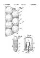
- FIG. 1is a 4th order structure spheres forming the base of an osteoblast
- FIG. 2is a schematic representation of a dense third order sphere pack with a 4th order spherical structure and indications of bone ingrowth
- FIG. 3is a schematic representation of two spherical elementary bodies with a coating mass with spherical fillers and fiber reinforced matrix
- FIG. 4is a view corresponding to FIG. 3 with stocking-shaped fillers impregnated through the matrix
- FIGS. 5a and 5bare views corresponding to FIG. 4 with bead chain-shaped fillers
- FIGS. 6 & 7are a bone dowel and medullar cavity closures made of bone replacement material according to the invention.
- FIGS. 8-10are further embodiments and uses of the material.
- Firmly anchored spheres 52 or spherical parts 15 to 50 ⁇ m in size, in particular 20 ⁇ m in size,have been found to represent the optimally structured surface (4th order ultrastructure) which an osteoblast 50 can recognize as its base; see FIG. 1.
- the spherical particle's diameter dis preferably approximately 20 ⁇ m and has the same magnitude as an osteoblast 50.
- the pores of highly porous fillerscan be filled with an absorbable and compatible substance.
- This substanceis preferably the binder used.
- bindersare: polypeptides, polylactates, polyglycolates or their co-condensates, gelatine, collagen and calcium compounds.
- the fillersare preferably harder than the binder.
- An organic matrixwas found to form an osteoblast layer much more quickly than a metal or ceramic surface.
- a ceramic surfacewas found to be better colonized than a metal surface.
- the surface of sintered apatiteundergoes even more rapid cell colonization than a ceramic surface.
- a collagen matrixwas also found to be colonized (populated) more quickly by cells than a pure ceramic or a pure apatite surface. The best colonization rates are achieved when the organic matrix (e.g. collagen) contains tiny spheres of apatite.
- This coating massis a preferred embodiment of the invention's 4th order structure (ultrastructure).
- the invention's coating mass 40is completely absorbable.
- a completely absorbable matrixhas great advantages compared to a nonabsorbable matrix. It is absorbed very quickly in the load-bearing zones and replaced by bone.
- a closed osteoblast layer 50can be obtained in a very short time from a dense 3rd order sphere pack (see FIG. 2) together with a thin collagen coat which remains over the spheres 30. This osteoblast layer is capable of forming lamellar bone able to withstand heavy loads. Due to the density of the sphere pack and its concrete size, the primary arrangement of the bone-building cells has a specific structure; thus, a rearrangement of the cells and the trabeculae undergoing formation is not necessary. As a result, the absorption and new bone formation (remodelling) stages are not necessary.
- part of the coating mass's fillerstake the form of fibers 43.
- the filamentous fillerspreferably consist of fibers 43 of differing length with a thickness of between 100 and 300 ⁇ m, preferably approximately 200 ⁇ m.
- the fibersare preferably greater than 2 and up to 15 millimeters in length, most preferably at least 3 millimeters and at most 10 millimeters in length, the optimal length being between 4 and 5 millimeters.
- Filamentous fillers 43can consist of substances such as carbon collagen, polypeptides, polyacetates, polyglycolates or their co-condensates, gelatine or catgut.
- the share of filamentous fillers 43can range from approximately 5 to 15%, preferably approximately 10%.
- the filamentous fillersare part of a closed network sheathing the matrix.
- a network structurecan be made up of bead chains 42, the beads having a diameter of between 15 and 50 ⁇ m, preferably approximately 20 ⁇ m.
- the beadsare so densely packed that they abut in a three-dimensional structure.
- the networkscan be arranged as a stocking, in particular a multi-layered stocking.
- a collagen massis produced from animal bones. It can be mixed like a glue with spherical apatite or TCP.
- ⁇ apatite ⁇preferably means ⁇ hydroxyl apatite ⁇ and ⁇ TCP ⁇ means ⁇ tricalcium phosphate ⁇ .
- a dense pack of spheresis produced using infrasound, vibrators and/or other agitators.
- the supporting framework of elementary bodiesis then impregnated with this coating mass.
- a structureis obtained in which the 3rd and 4th order structures of the invention are combined. This structure represents one of the invention's preferred bone replacement materials.
- a 3rd order bone replacement material combined with the 4th order ultrastructurecan also be obtained in the following manner: Spheres of an optimal size of between 200 and 3,000 ⁇ m are made from the collagen mass described above which contains apatite or TCP. These spheres are then placed on absorbable threads to form bead chains. Said chains are made into continuous stockings on a circular knitting machine. A bead chain network is formed.
- implantse.g. for the treatment of bone deficiencies
- Various forms of implantscan be produced by turning these bead chain structures in and out.
- the mechanical stability of the bone replacement material of the inventioncan be improved considerably by incorporating threads or fibers 36 of varying length or thread networks or thread webs into the matrix; see FIG. 3. Such bone replacement materials are also preferred embodiments.
- An especially preferred embodimentis the use of a knitted stocking or a network 48 in one or more layers as the filler. This is then impregnated with the binding substance.
- the laminations on the prostheses' anchoring parts which are obtained in this wayare also preferred. These present very pronounced mechanical resistance; see FIG. 4.
- Bone formationcan be stimulated in a particularly effective way when the stockings take the shape of bead chains 42; see FIGS. 5a and 5b.
- Such bead chains 42can be obtained by incorporating tiny apatite spheres (15 to 30 ⁇ m, preferably 20 ⁇ m) in the threads when the latter are extruded. Such embodiments are also preferred. Multi-layered, three dimensional bead chain structures can also be used instead of the single-layered chain beads according to FIGS. 5a and 5b.
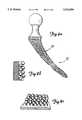
- FIG. 6shows an example of a bone dowel 10 to anchor bone screws made of the bone replacement material of the invention.
- the bone replacement materialincludes substantially spherical elementary bodies having a size of at least 200 ⁇ m and being together such that each elementary body is held in rigid contact with at least three adjacent elementary bodies to define enclosed spaces therebetween which provide for bone ingrowth and penetration, wherein the elementary bodies are provided and coated on the bone dowel.
- the bone dowel 10has five rings or bulges 12, a nearly semi-spherical front end 14 and a cylindrical end section 16.
- Spherical elementary bodies 18form the matrix structure consisting of spheres which is sheathed by network 19. After being incorporated into bone, the dowel 10 sheathes and/or reinforces the bone.
- the dowelis securely positioned in the surrounding bone and can provide a screw with long-term tensile strength when a screw is inserted into it.
- Anchoring in the boneis achieved by swelling the dowel or spreading it by screwing in a screw.
- the dowelcan be provided with a number of longitudinal or transverse grooves to facilitate its insertion in bone, or it may consist of a double-walled stocking cage in accordance with the dowel presented in FIG. 6.
- the bead chainsare held in this cage and connected with one another to form a supporting framework when the cage is turned.
- FIG. 7shows a medullary cavity closure 20 made of the bone replacement material of the invention.
- the bone replacement materialincludes substantially spherical elementary bodies having a size of at least 200 ⁇ m and being together such that each elementary body is held in rigid contact with at least three adjacent elementary bodies to define enclosed spaces therebetween which provide for bone ingrowth and penetration, wherein the elementary bodies are provided in the form of the medullary cavity closure and used to close the medullary cavity.
- the closure 20presents a cap 22 over the medullary cavity stump, a cone-shaped plug 24 and a cone-shaped ring 26 into which the plug 24 is inserted by turning a screw 28.
- the ring 26is then spread outwardly and is rigidly engaged in the interior of the honeycomb structure of the bone tubes schematically depicted in FIG. 7.
- Closures made of the bone replacement material of the invention in the form of simple cylinders which swell in bone, or massive lamellar cylinders or screwsare suitable means of treating bone gaps and filling holes in bone. They are inserted into the canal left by bone screws following their removal. Such closures create a hermetic seal against the internal pressure in the bone canals and/or medullary canals, prevent secondary hemorrhaging and the formation of hemotomae and accelerate bone healing.
- FIG. 8aGap filling sponges 80 (see FIG. 8a) in all shapes can be produced by turning these bead chain structures in and out. These are the familiar "scouring pad” shapes. They can be easily locked into bone gaps by spreading their "navel”. They can be spread using a cone or peg-like stopper.
- FIG. 8b and 8cshow a perspective diagram of a view on and a cross-section of one layer in the three-dimensional bead chain network.
- the bone replacement materialincluding substantially spherical elementary bodies having a size of at least 200 ⁇ m and held together such that each elementary body is held in rigid contact with at least three adjacent elementary bodies to define enclosed spaces therebetween which provide for bone ingrowth and penetration, can also be provided or coated on a prosthetic pin or stem to treat bone gaps.
- the coatshrinks while drying on the prosthesis' anchoring part, thus resulting in a closed contact between the supporting framework, the matrix coat, the fillers and the base material.
- a prosthesis coated in this waycan be inserted in the bone without bone cement as a binder. With the appropriate support, closed bone-building layers are formed on the surface. They can give the prosthetic components a stable, bone support. Pronounced supporting trabeculae are formed, next to which the matrix coat is absorbed. The bone can then grow deep into the surface structure of the base body (supporting framework).
- FIG. 9ashows the anchoring part 90 of a prosthesis 92 of the invention onto which the material of the invention has been applied.
- Said materialconsists of a bead chain structure.
- FIG. 9bshows a schematic cross-section of the base material and two layers of the three-dimensional structure.
- FIG. 9cshows a view on the uppermost layer in the structure.
- the 3rd order structurecan be both part of the prosthetic stem or part of the coat. If the absorbable coat consists of 3rd and 4th order shaping elements, the metal prosthetic stem must either have supporting ribs or continuous pores to permit bone ingrowth and bone underpinning.
- Osteogenesis and bone ingrowthis much more rapid at the implant due to the inducing effect of the small apatite spheres coated, for example, with collagen than is the case in conventional coatings or non-coated implants.
- the bone replacement materialitself makes up the entire implant or the anchoring part of a prosthesis.
- the materialis given the appropriate shape during production.
- the elementary bodies in the supporting frameworkcan be a three-dimensional network strongly braced by inner or outer struts.
- the simplest form of implantwould be sintered spheres. Such sphere packing can also be achieved by tying externally (retainer cage).
- bead chainscan be processed and braced, either by an inner, pressure-absorbing skeleton such as a supporting rib design or a "tire”, or stiffened by means of individual weld points with adjustable elasticity.
- the stiffness and elasticity of certain parts of the bone replacement materialcan be set by the number and density of the weld points which can firmly connect the beads to one another.
- FIG. 10shows an anchoring part 100 in which the network 102 can be both a sheath and--following the required stiffening or bracing--anchoring part.
- Artificial bonesfor instance for tutorial purposes or for operation courses, can also be advantageously produced from the bone replacement material of the invention.
- a three-dimensional network of the spherical elementary bodiescan be turned or interlaced in such a way that implants with differing elasticities result (e.g. in different sections of the implant).
- the bone replacement material of the inventioncan take the form of a coat, a sheath, a cylinder, a flat coil spring, a sphere or a sponge.
- the induced bone formationcan be further increased by adding chemically active substances to the matrix substance.
- Chemotactically active substances from bone matrix and necrotic boneare known, for example, which contain "bone morphogenic proteins" and exert an especially great inducing effect on bone formation. Adding such admixtures is preferred.
- Induced bone formationhas been shown to be particularly favored when the highly porous spherical particles used as fillers are harder than the surrounding matrix. This allows them to exert a mechanically stimulating effect on the bone-building cell. Such an embodiment is also preferred.
- Bone replacement material of the inventioncontains a considerable amount of binding substance. This has been found to possess a great capacity with good release rates regarding the admixtures of active substances. Implants which have no access to the body's defense mechanisms due to a lack of vascularization are known to be at risk since they can easily be colonized by bacteria. This can be prevented by adding an antibiotic to the bone replacement material. A great deal of research his been conducted on such antibiotic admixtures in bone cements. To date, cement-free prostheses do not possess this protection. Bone replacement materials consisting of absorbable substances, however, make it possible to provide cement-free prostheses and implants of all kinds with an effective prophylactic protection against infection.
- hemostatic agentsare known from external treatments.
- such substancescan also take effect at organs not accessible to external treatment.
- Hemostatic agents in the binding substanceprovide an immediate hemorrhage control in the bone bed.
- Vaso-active substancessuch as noradrenalin or one of its derivatives also provide hemorrhage control due to the vasoconstriction they cause. A soaking of the interface with blood is thus prevented and the mechanical strength of the interface is maintained for a longer period of time.
- bone-inducing, chemotactically active substancescan be admixed to the binding substance. These cause new bone formation to set in more quickly.
- Hormone applicationstake a local effect with substances such as calcitonin. These prevent the newly formed bone from being resorbed.
- a bone replacement materialconsisting of a three-dimensional supporting framework or elementary bodies in contact with one another and surrounding defined spaces, with or without a coating mass, can be produced as follows:
- the absorbable organic matrix substance polypeptidee.g. polyglycolate or polylactate, together with the admixture of various additives as softeners, are heated in an extruder until they melt.
- the tricalcium phosphate spheresare preferably obtained from a highly porous sintered tricalcium phosphate, which for the most part presents a beta-whitlocked structure, by grinding in a ball mill.
- a molten massresults with homogeneous filler distribution from stirring.
- Pressureis applied and the material in the molten mass is pressed out through fine nozzles and rolled in precipitation baths to threads with a thickness of approximately 200 ⁇ m.
- the spherical or spherical-like structures on the threadscan be obtained in various ways. Spheres with a larger diameter, e.g. approximately 1,000 to 3,000 ⁇ m, can be threaded purely mechanically or the diameter of the infinitely variable nozzle opening can be changed by pulsation. The latter is the preferred method, in particular for spheres with a smaller diameter such as approximately 500 ⁇ m.
- the bead chains obtained in this waycan then be knit to form continuous stockings on continuous round knitting machines produced, for example, by the Muller Co. in Weissenburg or the Dubied Co. in Neuenburg, Switzerland.
- a very dense, three-dimensional network of bead chainsresults. Its external shape resembles that of a tire. It can be ideally blocked in the bone cavity by means of a central spreader.
- Layered corpuscular networkscan also be formed by turning such networks outwardly. This is achieved by knitting or welding metal bead chains into networks, turning them outwardly in a few or several layers and stiffening them by welding. This makes it possible to set various elasticities over the entire implant.
- a very simple methodconsists of turning such networks over a core so that they completely enclose the core in a stocking-like manner. After turning the stocking 180°, for instance, a second layer can be turned. This process can be repeated until this continuous bead chain stocking possesses a multi-layered stratification.
- a second processconsists of welding and stiffening the framework of corpuscular layered networks according to a precisely calculated plan.
- An additional stiffeningresults from filling the cavity with an organic matrix substance, with or without filler particles presenting a 4th order structure.
- the matrix and filler particlesare characterized by the fact that they are absorbable and can be coated with materials.
- Anchoring parts with up to two layers of corpuscular networkscan be produced at reasonable costs using conventional methods.
- Producing the 3rd order structureis based on the process of casting into a lost form. This form is produced using layered networks of wax spheres as a meltable model. These processes are known from dentistry and are based on all simple surface structurings on cast metal shafts.
- the supporting framework obtained in this wayis coated with an organic matrix if it is used to fill in cavities.
- the coating materialpreferably includes filler particles and exhibits all characteristics of the 4th order structure described above. Coating can be achieved by dipping the 3rd order structure into a molten mass of the 4th order structure.
- the bone replacement material without a coating mass which consists of the three-dimensional supporting frame of the 3rd order structure of elementary bodiescan also be used as a starting material for artificial bones.
- a casting compositione.g. made of plastic
- the elementary bodiesare then removed from the casting composition leaving only the bone-shaped structure of the casting composition.
- the elementary bodiesare made of a material which is chemically soluble in a solvent which does not affect the casting composition, or the elementary bodies are physically, e.g. electrolytically, removed from the casting composition.
Landscapes
- Health & Medical Sciences (AREA)
- Life Sciences & Earth Sciences (AREA)
- Animal Behavior & Ethology (AREA)
- General Health & Medical Sciences (AREA)
- Public Health (AREA)
- Veterinary Medicine (AREA)
- Chemical & Material Sciences (AREA)
- Oral & Maxillofacial Surgery (AREA)
- Epidemiology (AREA)
- Transplantation (AREA)
- Medicinal Chemistry (AREA)
- Dermatology (AREA)
- Vascular Medicine (AREA)
- Heart & Thoracic Surgery (AREA)
- Engineering & Computer Science (AREA)
- Orthopedic Medicine & Surgery (AREA)
- Surgery (AREA)
- Cardiology (AREA)
- Biomedical Technology (AREA)
- Ceramic Engineering (AREA)
- Dentistry (AREA)
- Dispersion Chemistry (AREA)
- Inorganic Chemistry (AREA)
- Composite Materials (AREA)
- Materials Engineering (AREA)
- Materials For Medical Uses (AREA)
- Prostheses (AREA)
Abstract
Description
Claims (18)
Priority Applications (1)
| Application Number | Priority Date | Filing Date | Title |
|---|---|---|---|
| US08/039,517US5522894A (en) | 1984-12-14 | 1993-03-29 | Bone replacement material made of absorbable beads |
Applications Claiming Priority (10)
| Application Number | Priority Date | Filing Date | Title |
|---|---|---|---|
| DE19843445711DE3445711A1 (en) | 1984-12-14 | 1984-12-14 | BONE REPLACEMENT MATERIAL AND ITS USE |
| DE19843445731DE3445731A1 (en) | 1984-12-14 | 1984-12-14 | Material and use thereof |
| DE3445711.9 | 1984-12-14 | ||
| US90244286A | 1986-08-14 | 1986-08-14 | |
| US27142088A | 1988-11-10 | 1988-11-10 | |
| US40304589A | 1989-08-31 | 1989-08-31 | |
| US52834790A | 1990-05-22 | 1990-05-22 | |
| US65110491A | 1991-02-04 | 1991-02-04 | |
| US93564792A | 1992-08-26 | 1992-08-26 | |
| US08/039,517US5522894A (en) | 1984-12-14 | 1993-03-29 | Bone replacement material made of absorbable beads |
Related Parent Applications (1)
| Application Number | Title | Priority Date | Filing Date |
|---|---|---|---|
| US93564792AContinuation | 1984-12-14 | 1992-08-26 |
Publications (1)
| Publication Number | Publication Date |
|---|---|
| US5522894Atrue US5522894A (en) | 1996-06-04 |
Family
ID=27570565
Family Applications (1)
| Application Number | Title | Priority Date | Filing Date |
|---|---|---|---|
| US08/039,517Expired - LifetimeUS5522894A (en) | 1984-12-14 | 1993-03-29 | Bone replacement material made of absorbable beads |
Country Status (1)
| Country | Link |
|---|---|
| US (1) | US5522894A (en) |
Cited By (46)
| Publication number | Priority date | Publication date | Assignee | Title |
|---|---|---|---|---|
| US5746200A (en)* | 1990-10-19 | 1998-05-05 | Draenert; Klaus | Trabecula nasal filter having both macropores and micropores |
| WO1999016478A1 (en)* | 1997-10-01 | 1999-04-08 | Phillips-Origen Ceramic Technology, Llc | Bone substitutes |
| WO1999016479A1 (en)* | 1997-10-01 | 1999-04-08 | Phillips-Origen Ceramic Technology, Llc. | Bone substitute materials |
| US5958314A (en)* | 1994-02-04 | 1999-09-28 | Draenert; Klaus | Process for the preparation of porous material |
| US5993716A (en)* | 1990-10-19 | 1999-11-30 | Draenert; Klaus | Material and process for its preparation |
| EP0875217A3 (en)* | 1997-04-15 | 2000-08-30 | Advanced Cardiovascular Systems, Inc. | Method of manufacturing a medicated porous metal prosthesis |
| EP0875218A3 (en)* | 1997-04-15 | 2000-08-30 | Advanced Cardiovascular Systems, Inc. | Porous medicated stent |
| US6127596A (en)* | 1998-01-23 | 2000-10-03 | Sulzer Orthopedics Inc. | Implantable orthopedic prosthesis having tissue attachment surface and method of manufacture |
| US6187046B1 (en)* | 1997-03-14 | 2001-02-13 | Asahi Kogaku Kogyo Kabushiki Kaisha | Prosthetic bone material and process for the production of the same |
| US6200346B1 (en)* | 1996-04-10 | 2001-03-13 | Sulzer Orthopaedie Ag | Metal implant with anchoring surface |
| DE10026620A1 (en)* | 2000-05-29 | 2002-03-07 | Gerhard Quelle | Biocompatible material for cell and tissue implantation, useful e.g. for drug release or cosmetic tissue augmentation, consisting of spherical particles having (semi-)permeable or porous outer shell and internal cavity |
| DE10055465A1 (en)* | 2000-11-09 | 2002-05-23 | Blz Gmbh | Material useful for making bone replacement implants comprises nonmetallic inorganic filler particles embedded in a laser-sinterable biocompatible polymer matrix |
| US20030180376A1 (en)* | 2001-03-02 | 2003-09-25 | Dalal Paresh S. | Porous beta-tricalcium phosphate granules and methods for producing same |
| US20040081704A1 (en)* | 1998-02-13 | 2004-04-29 | Centerpulse Biologics Inc. | Implantable putty material |
| US6805898B1 (en) | 2000-09-28 | 2004-10-19 | Advanced Cardiovascular Systems, Inc. | Surface features of an implantable medical device |
| US20040243246A1 (en)* | 2003-05-27 | 2004-12-02 | Lyren Philip S. | Hip implant with porous body |
| US20050112397A1 (en)* | 2003-07-24 | 2005-05-26 | Rolfe Jonathan L. | Assembled non-random foams |
| US20050118344A1 (en)* | 2003-12-01 | 2005-06-02 | Pacetti Stephen D. | Temperature controlled crimping |
| US20060093729A1 (en)* | 1997-10-01 | 2006-05-04 | Marx Jeffrey G | Process for producing rigid reticulated articles |
| US20070009557A1 (en)* | 2005-06-22 | 2007-01-11 | Heraeus Kulzer Gmbh | Moldable implant material |
| US7255712B1 (en) | 1997-04-15 | 2007-08-14 | Active Implants Corporation | Bone growth promoting implant |
| US7572295B2 (en) | 2001-12-04 | 2009-08-11 | Active Implants Corporation | Cushion bearing implants for load bearing applications |
| US20090254182A1 (en)* | 2008-04-02 | 2009-10-08 | John Kovarik | Intervertebral implant devices for supporting vertebrae and devices and methods for insertion thereof |
| US7718616B2 (en) | 2006-12-21 | 2010-05-18 | Zimmer Orthobiologics, Inc. | Bone growth particles and osteoinductive composition thereof |
| US7758653B2 (en) | 2002-05-23 | 2010-07-20 | Active Implants Corporation | Implants |
| US20100185290A1 (en)* | 2007-06-29 | 2010-07-22 | Curtis Compton | Flexible chain implants and instrumentation |
| US20100249830A1 (en)* | 2007-11-30 | 2010-09-30 | Nelson Christopher M | Expandable plugs and related delivery apparatuses and methods |
| US20100292795A1 (en)* | 2009-05-13 | 2010-11-18 | Jensen Ole T | Biomedical implant surface topography |
| US20110008529A1 (en)* | 1999-09-03 | 2011-01-13 | Advanced Cardiovascular Systems, Inc. | Thermal Treatment Of An Implantable Medical Device |
| EP2305324A1 (en) | 1999-03-25 | 2011-04-06 | Metabolix, Inc. | Medical devices and applications of polyhydroxyalkanoate polymers |
| US8172897B2 (en) | 1997-04-15 | 2012-05-08 | Advanced Cardiovascular Systems, Inc. | Polymer and metal composite implantable medical devices |
| CN102784017A (en)* | 2012-07-09 | 2012-11-21 | 济南大学 | Manufacture process of artificial bone made of composite material |
| US20130006354A1 (en)* | 2010-02-26 | 2013-01-03 | Limacorporate Spa | Integrated prosthetic element |
| US8613938B2 (en) | 2010-11-15 | 2013-12-24 | Zimmer Orthobiologics, Inc. | Bone void fillers |
| US8690874B2 (en) | 2000-12-22 | 2014-04-08 | Zimmer Orthobiologics, Inc. | Composition and process for bone growth and repair |
| US20140134258A1 (en)* | 2010-11-08 | 2014-05-15 | Consiglio Nazionale Delle Ricerche | Implants for "load bearing" bone substitutions having hierarchical organized architecture deriving from transformation of vegetal structures |
| US8765189B2 (en) | 2011-05-13 | 2014-07-01 | Howmedica Osteonic Corp. | Organophosphorous and multivalent metal compound compositions and methods |
| US20150374503A1 (en)* | 2014-06-30 | 2015-12-31 | Bacterin International, Inc. | Implant for fusion between adjacent bone bodies |
| US20160038260A1 (en)* | 2000-05-09 | 2016-02-11 | Ben-Zion Karmon | Methods for displacing the schneiderian membrane |
| US9265857B2 (en) | 2010-05-11 | 2016-02-23 | Howmedica Osteonics Corp. | Organophosphorous, multivalent metal compounds, and polymer adhesive interpenetrating network compositions and methods |
| US9289240B2 (en) | 2005-12-23 | 2016-03-22 | DePuy Synthes Products, Inc. | Flexible elongated chain implant and method of supporting body tissue with same |
| US20160296306A1 (en)* | 2013-12-19 | 2016-10-13 | Heraeus Kulzer Gmbh | Process for producing superstructures for dental prostheses by stratification on preformed elements |
| US10028851B2 (en) | 1997-04-15 | 2018-07-24 | Advanced Cardiovascular Systems, Inc. | Coatings for controlling erosion of a substrate of an implantable medical device |
| WO2019023807A1 (en) | 2017-08-03 | 2019-02-07 | Benoit Benoit | Plug for bone tissue |
| USD907771S1 (en) | 2017-10-09 | 2021-01-12 | Pioneer Surgical Technology, Inc. | Intervertebral implant |
| US11147682B2 (en) | 2017-09-08 | 2021-10-19 | Pioneer Surgical Technology, Inc. | Intervertebral implants, instruments, and methods |
Citations (29)
| Publication number | Priority date | Publication date | Assignee | Title |
|---|---|---|---|---|
| DE837294C (en)* | 1949-04-25 | 1952-04-21 | Maison Drapier Van Steenbruggh | Bone Joint Prosthesis |
| DE2022498A1 (en)* | 1969-05-12 | 1970-12-17 | Fmc Corp Inc | Prosthetic structures as derivatives of collagen |
| DE2127843A1 (en)* | 1970-06-04 | 1971-12-16 | Ontario Research Foundation, Onta no (Kanada) | Metallic implants |
| DE2205808A1 (en)* | 1972-02-02 | 1973-08-16 | Sulzer Ag | SHAFT FOR BONE IMPLANTS |
| DE2502884A1 (en)* | 1975-01-24 | 1976-07-29 | Juergen J Dipl Phy Hildebrandt | Synthetic bone or joint prosthesis - incorporates zones which are gradually absorbed by the body |
| US4051598A (en)* | 1974-04-23 | 1977-10-04 | Meer Sneer | Dental implants |
| DE2620907A1 (en)* | 1976-05-12 | 1977-11-17 | Battelle Institut E V | ANCHORING FOR HIGHLY LOADED ENDOPROSTHESES |
| DE2620809A1 (en)* | 1976-05-11 | 1977-11-17 | Orenstein & Koppel Ag | Control system for profiling and embankment excavator - has angle sensors for generating data for automatic operation (NL 15.11.77) |
| DE2730004A1 (en)* | 1976-07-02 | 1978-01-12 | Benoist Girard & Cie | PROCESS FOR MANUFACTURING A WORKPIECE WITH A GRAINY SURFACE, IN PARTICULAR SURGICAL PROSTHESIS |
| DE2742128A1 (en)* | 1976-09-20 | 1978-03-23 | Inst Nat Sante Rech Med | BONE REPLACEMENT MATERIAL AND THEIR USE |
| CH611794A5 (en)* | 1976-09-08 | 1979-06-29 | Rizh Nii Travmatologii I Ortop | Endoprosthesis |
| US4177524A (en)* | 1976-05-14 | 1979-12-11 | Pfaudler-Werke A.G. | Medical securement element with abrasive grains on thread surface |
| US4192021A (en)* | 1976-05-12 | 1980-03-11 | Batelle-Institut e.V. | Bone replacement or prosthesis anchoring material |
| DE2917037B1 (en)* | 1979-04-27 | 1980-04-17 | Josef Dipl-Chem Dr Gaensheimer | Parenteral drug-containing partially absorbable multicomponent mass based on polymeric substances |
| US4206516A (en)* | 1976-12-15 | 1980-06-10 | Ontario Research Foundation | Surgical prosthetic device or implant having pure metal porous coating |
| EP0011809A1 (en)* | 1978-11-22 | 1980-06-11 | Battelle-Institut e.V. | Intermediate layer for securing a prosthesis |
| DE2854490B1 (en)* | 1978-12-16 | 1980-06-12 | Braun Melsungen Ag | Bone replacement material with improved biological stability based on collagen |
| EP0016906A1 (en)* | 1979-02-16 | 1980-10-15 | MERCK PATENT GmbH | Bone cement and method for its production |
| US4230455A (en)* | 1976-06-07 | 1980-10-28 | Asahi Kogaku Kogyo Kabushiki Kaisha | Prosthetic teeth and bones |
| US4347234A (en)* | 1978-01-09 | 1982-08-31 | Merck Patent Gesellschaft Mit Beschrankter Haftung | Medicinally useful, shaped mass of collagen resorbable in the body |
| US4365357A (en)* | 1979-04-28 | 1982-12-28 | Merck Patent Gesellschaft Mit Beschrankter Haftung | Surgical materials suitable for use with bone cements |
| WO1983003967A1 (en)* | 1982-05-07 | 1983-11-24 | MERCK Patent Gesellschaft mit beschränkter Haftung | Surgical accessory |
| CH643732A5 (en)* | 1978-01-01 | 1984-06-29 | Scheicher Hans | Aid for covering and/or filling bone defects and process for the production thereof |
| US4542539A (en)* | 1982-03-12 | 1985-09-24 | Artech Corp. | Surgical implant having a graded porous coating |
| US4544359A (en)* | 1984-01-13 | 1985-10-01 | Pentron Corporation | Dental restorative material |
| US4644942A (en)* | 1981-07-27 | 1987-02-24 | Battelle Development Corporation | Production of porous coating on a prosthesis |
| US4655777A (en)* | 1983-12-19 | 1987-04-07 | Southern Research Institute | Method of producing biodegradable prosthesis and products therefrom |
| US4713076A (en)* | 1984-04-19 | 1987-12-15 | Klaus Draenert | Coating composition and anchorage component for surgical implants |
| US4992226A (en)* | 1985-03-28 | 1991-02-12 | Collagen Corporation | Method of making molds with xenogeneic collagen/mineral preparations for bone repair |
- 1993
- 1993-03-29USUS08/039,517patent/US5522894A/ennot_activeExpired - Lifetime
Patent Citations (33)
| Publication number | Priority date | Publication date | Assignee | Title |
|---|---|---|---|---|
| DE837294C (en)* | 1949-04-25 | 1952-04-21 | Maison Drapier Van Steenbruggh | Bone Joint Prosthesis |
| DE2022498A1 (en)* | 1969-05-12 | 1970-12-17 | Fmc Corp Inc | Prosthetic structures as derivatives of collagen |
| DE2127843A1 (en)* | 1970-06-04 | 1971-12-16 | Ontario Research Foundation, Onta no (Kanada) | Metallic implants |
| US3855638A (en)* | 1970-06-04 | 1974-12-24 | Ontario Research Foundation | Surgical prosthetic device with porous metal coating |
| DE2205808A1 (en)* | 1972-02-02 | 1973-08-16 | Sulzer Ag | SHAFT FOR BONE IMPLANTS |
| US3848273A (en)* | 1972-02-02 | 1974-11-19 | Sulzer Ag | Shank for bone implants |
| US4051598A (en)* | 1974-04-23 | 1977-10-04 | Meer Sneer | Dental implants |
| DE2502884A1 (en)* | 1975-01-24 | 1976-07-29 | Juergen J Dipl Phy Hildebrandt | Synthetic bone or joint prosthesis - incorporates zones which are gradually absorbed by the body |
| DE2620809A1 (en)* | 1976-05-11 | 1977-11-17 | Orenstein & Koppel Ag | Control system for profiling and embankment excavator - has angle sensors for generating data for automatic operation (NL 15.11.77) |
| DE2620907A1 (en)* | 1976-05-12 | 1977-11-17 | Battelle Institut E V | ANCHORING FOR HIGHLY LOADED ENDOPROSTHESES |
| US4192021A (en)* | 1976-05-12 | 1980-03-11 | Batelle-Institut e.V. | Bone replacement or prosthesis anchoring material |
| US4177524A (en)* | 1976-05-14 | 1979-12-11 | Pfaudler-Werke A.G. | Medical securement element with abrasive grains on thread surface |
| US4230455A (en)* | 1976-06-07 | 1980-10-28 | Asahi Kogaku Kogyo Kabushiki Kaisha | Prosthetic teeth and bones |
| DE2730004A1 (en)* | 1976-07-02 | 1978-01-12 | Benoist Girard & Cie | PROCESS FOR MANUFACTURING A WORKPIECE WITH A GRAINY SURFACE, IN PARTICULAR SURGICAL PROSTHESIS |
| CH611794A5 (en)* | 1976-09-08 | 1979-06-29 | Rizh Nii Travmatologii I Ortop | Endoprosthesis |
| DE2742128A1 (en)* | 1976-09-20 | 1978-03-23 | Inst Nat Sante Rech Med | BONE REPLACEMENT MATERIAL AND THEIR USE |
| GB1593288A (en)* | 1976-09-20 | 1981-07-15 | Inst Nat Sante Rech Med | Bone prosthetic material |
| US4206516A (en)* | 1976-12-15 | 1980-06-10 | Ontario Research Foundation | Surgical prosthetic device or implant having pure metal porous coating |
| CH643732A5 (en)* | 1978-01-01 | 1984-06-29 | Scheicher Hans | Aid for covering and/or filling bone defects and process for the production thereof |
| US4347234A (en)* | 1978-01-09 | 1982-08-31 | Merck Patent Gesellschaft Mit Beschrankter Haftung | Medicinally useful, shaped mass of collagen resorbable in the body |
| EP0011809A1 (en)* | 1978-11-22 | 1980-06-11 | Battelle-Institut e.V. | Intermediate layer for securing a prosthesis |
| DE2854490B1 (en)* | 1978-12-16 | 1980-06-12 | Braun Melsungen Ag | Bone replacement material with improved biological stability based on collagen |
| US4373217A (en)* | 1979-02-16 | 1983-02-15 | Merck Patent Gesellschaft Mit Beschrankter Haftung | Implantation materials and a process for the production thereof |
| EP0016906A1 (en)* | 1979-02-16 | 1980-10-15 | MERCK PATENT GmbH | Bone cement and method for its production |
| DE2917037B1 (en)* | 1979-04-27 | 1980-04-17 | Josef Dipl-Chem Dr Gaensheimer | Parenteral drug-containing partially absorbable multicomponent mass based on polymeric substances |
| US4365357A (en)* | 1979-04-28 | 1982-12-28 | Merck Patent Gesellschaft Mit Beschrankter Haftung | Surgical materials suitable for use with bone cements |
| US4644942A (en)* | 1981-07-27 | 1987-02-24 | Battelle Development Corporation | Production of porous coating on a prosthesis |
| US4542539A (en)* | 1982-03-12 | 1985-09-24 | Artech Corp. | Surgical implant having a graded porous coating |
| WO1983003967A1 (en)* | 1982-05-07 | 1983-11-24 | MERCK Patent Gesellschaft mit beschränkter Haftung | Surgical accessory |
| US4655777A (en)* | 1983-12-19 | 1987-04-07 | Southern Research Institute | Method of producing biodegradable prosthesis and products therefrom |
| US4544359A (en)* | 1984-01-13 | 1985-10-01 | Pentron Corporation | Dental restorative material |
| US4713076A (en)* | 1984-04-19 | 1987-12-15 | Klaus Draenert | Coating composition and anchorage component for surgical implants |
| US4992226A (en)* | 1985-03-28 | 1991-02-12 | Collagen Corporation | Method of making molds with xenogeneic collagen/mineral preparations for bone repair |
Cited By (95)
| Publication number | Priority date | Publication date | Assignee | Title |
|---|---|---|---|---|
| US5746200A (en)* | 1990-10-19 | 1998-05-05 | Draenert; Klaus | Trabecula nasal filter having both macropores and micropores |
| US5993716A (en)* | 1990-10-19 | 1999-11-30 | Draenert; Klaus | Material and process for its preparation |
| US6221477B1 (en) | 1994-02-04 | 2001-04-24 | Klaus Draenert | Material and process for producing the same |
| US5958314A (en)* | 1994-02-04 | 1999-09-28 | Draenert; Klaus | Process for the preparation of porous material |
| US6200346B1 (en)* | 1996-04-10 | 2001-03-13 | Sulzer Orthopaedie Ag | Metal implant with anchoring surface |
| US6187046B1 (en)* | 1997-03-14 | 2001-02-13 | Asahi Kogaku Kogyo Kabushiki Kaisha | Prosthetic bone material and process for the production of the same |
| EP1527754A1 (en)* | 1997-04-15 | 2005-05-04 | Advanced Cardiovascular Systems, Inc. | Porous medicated stent |
| US6723120B2 (en) | 1997-04-15 | 2004-04-20 | Advanced Cardiovascular Systems, Inc. | Medicated porous metal prosthesis |
| US7699890B2 (en) | 1997-04-15 | 2010-04-20 | Advanced Cardiovascular Systems, Inc. | Medicated porous metal prosthesis and a method of making the same |
| EP0875218A3 (en)* | 1997-04-15 | 2000-08-30 | Advanced Cardiovascular Systems, Inc. | Porous medicated stent |
| EP0875217A3 (en)* | 1997-04-15 | 2000-08-30 | Advanced Cardiovascular Systems, Inc. | Method of manufacturing a medicated porous metal prosthesis |
| US8172897B2 (en) | 1997-04-15 | 2012-05-08 | Advanced Cardiovascular Systems, Inc. | Polymer and metal composite implantable medical devices |
| US6240616B1 (en) | 1997-04-15 | 2001-06-05 | Advanced Cardiovascular Systems, Inc. | Method of manufacturing a medicated porous metal prosthesis |
| US7255712B1 (en) | 1997-04-15 | 2007-08-14 | Active Implants Corporation | Bone growth promoting implant |
| US8007529B2 (en) | 1997-04-15 | 2011-08-30 | Advanced Cardiovascular Systems, Inc. | Medicated porous metal prosthesis |
| US10028851B2 (en) | 1997-04-15 | 2018-07-24 | Advanced Cardiovascular Systems, Inc. | Coatings for controlling erosion of a substrate of an implantable medical device |
| WO1999016478A1 (en)* | 1997-10-01 | 1999-04-08 | Phillips-Origen Ceramic Technology, Llc | Bone substitutes |
| US6527810B2 (en) | 1997-10-01 | 2003-03-04 | Wright Medical Technology, Inc. | Bone substitutes |
| US6136029A (en)* | 1997-10-01 | 2000-10-24 | Phillips-Origen Ceramic Technology, Llc | Bone substitute materials |
| WO1999016479A1 (en)* | 1997-10-01 | 1999-04-08 | Phillips-Origen Ceramic Technology, Llc. | Bone substitute materials |
| US6296667B1 (en) | 1997-10-01 | 2001-10-02 | Phillips-Origen Ceramic Technology, Llc | Bone substitutes |
| US7740897B2 (en) | 1997-10-01 | 2010-06-22 | Wright Medical Technology, Inc. | Process for producing rigid reticulated articles |
| US20060093729A1 (en)* | 1997-10-01 | 2006-05-04 | Marx Jeffrey G | Process for producing rigid reticulated articles |
| US6127596A (en)* | 1998-01-23 | 2000-10-03 | Sulzer Orthopedics Inc. | Implantable orthopedic prosthesis having tissue attachment surface and method of manufacture |
| US20080293617A1 (en)* | 1998-02-13 | 2008-11-27 | Benedict James J | Implantable Putty Material |
| US20040081704A1 (en)* | 1998-02-13 | 2004-04-29 | Centerpulse Biologics Inc. | Implantable putty material |
| US8497236B2 (en) | 1998-02-13 | 2013-07-30 | Zimmer Orthobiologics, Inc. | Implantable putty material |
| EP2305324A1 (en) | 1999-03-25 | 2011-04-06 | Metabolix, Inc. | Medical devices and applications of polyhydroxyalkanoate polymers |
| US8586125B2 (en) | 1999-09-03 | 2013-11-19 | Advanced Cardiovascular Systems, Inc. | Thermal treatment of an implantable medical device |
| US20110008529A1 (en)* | 1999-09-03 | 2011-01-13 | Advanced Cardiovascular Systems, Inc. | Thermal Treatment Of An Implantable Medical Device |
| US20160038260A1 (en)* | 2000-05-09 | 2016-02-11 | Ben-Zion Karmon | Methods for displacing the schneiderian membrane |
| DE10026620A1 (en)* | 2000-05-29 | 2002-03-07 | Gerhard Quelle | Biocompatible material for cell and tissue implantation, useful e.g. for drug release or cosmetic tissue augmentation, consisting of spherical particles having (semi-)permeable or porous outer shell and internal cavity |
| US20050033411A1 (en)* | 2000-09-28 | 2005-02-10 | Wu Steven Z. | Surface features of an implantable medical device |
| US20050033412A1 (en)* | 2000-09-28 | 2005-02-10 | Wu Steven Z. | Method of making an implantable medical device |
| US7335314B2 (en) | 2000-09-28 | 2008-02-26 | Advanced Cardiovascular Systems Inc. | Method of making an implantable medical device |
| US6805898B1 (en) | 2000-09-28 | 2004-10-19 | Advanced Cardiovascular Systems, Inc. | Surface features of an implantable medical device |
| DE10055465A1 (en)* | 2000-11-09 | 2002-05-23 | Blz Gmbh | Material useful for making bone replacement implants comprises nonmetallic inorganic filler particles embedded in a laser-sinterable biocompatible polymer matrix |
| US8690874B2 (en) | 2000-12-22 | 2014-04-08 | Zimmer Orthobiologics, Inc. | Composition and process for bone growth and repair |
| US20050170012A1 (en)* | 2001-03-02 | 2005-08-04 | Stryker Corporation | Porous beta-tricalcium phosphate granules for regeneration of bone tissue |
| US20090110743A1 (en)* | 2001-03-02 | 2009-04-30 | Dalal Paresh S | Porous beta-tricalcium phosphate granules and methods for producing same |
| US8173149B2 (en) | 2001-03-02 | 2012-05-08 | Stryker Corporation | Method for producing porous β-tricalcium phosphate granules |
| US7390498B2 (en) | 2001-03-02 | 2008-06-24 | Stryker Corporation | Method of forming bone with porous βtricalcium phosphate granules |
| US7357941B2 (en) | 2001-03-02 | 2008-04-15 | Stryker Corporation | Method of delivering a bioactive agent with porous β-tricalcium phosphate granules |
| US20060292198A1 (en)* | 2001-03-02 | 2006-12-28 | Stryker Corporation | Porous beta-tricalcium phosphate granules for regeneration of bone tissue |
| US6949251B2 (en) | 2001-03-02 | 2005-09-27 | Stryker Corporation | Porous β-tricalcium phosphate granules for regeneration of bone tissue |
| US20030180376A1 (en)* | 2001-03-02 | 2003-09-25 | Dalal Paresh S. | Porous beta-tricalcium phosphate granules and methods for producing same |
| US7572295B2 (en) | 2001-12-04 | 2009-08-11 | Active Implants Corporation | Cushion bearing implants for load bearing applications |
| EP2145604A1 (en) | 2001-12-04 | 2010-01-20 | Active Implants Corporation | Cushion bearing implants for load bearing applications |
| US8814946B2 (en) | 2001-12-04 | 2014-08-26 | Active Implants Corporation | Cushion bearing implants for load bearing applications |
| US7758653B2 (en) | 2002-05-23 | 2010-07-20 | Active Implants Corporation | Implants |
| US8506642B1 (en)* | 2003-05-27 | 2013-08-13 | Philip Scott Lyren | Hip implant with porous body |
| US20040243246A1 (en)* | 2003-05-27 | 2004-12-02 | Lyren Philip S. | Hip implant with porous body |
| US20050112397A1 (en)* | 2003-07-24 | 2005-05-26 | Rolfe Jonathan L. | Assembled non-random foams |
| US7208222B2 (en) | 2003-07-24 | 2007-04-24 | Viasys Healthcare Inc. | Assembled non-random foams |
| USRE45744E1 (en) | 2003-12-01 | 2015-10-13 | Abbott Cardiovascular Systems Inc. | Temperature controlled crimping |
| US20050118344A1 (en)* | 2003-12-01 | 2005-06-02 | Pacetti Stephen D. | Temperature controlled crimping |
| US8052912B2 (en) | 2003-12-01 | 2011-11-08 | Advanced Cardiovascular Systems, Inc. | Temperature controlled crimping |
| EP1745806A3 (en)* | 2005-06-22 | 2007-10-03 | Heraeus Kulzer GmbH | Deformable implant material |
| US20070009557A1 (en)* | 2005-06-22 | 2007-01-11 | Heraeus Kulzer Gmbh | Moldable implant material |
| US10881520B2 (en) | 2005-12-23 | 2021-01-05 | DePuy Synthes Products, Inc. | Flexible elongated chain implant and method of supporting body tissue with same |
| US9956085B2 (en) | 2005-12-23 | 2018-05-01 | DePuy Synthes Products, Inc. | Flexible elongated chain implant and method of supporting body tissue with same |
| US9289240B2 (en) | 2005-12-23 | 2016-03-22 | DePuy Synthes Products, Inc. | Flexible elongated chain implant and method of supporting body tissue with same |
| US11701233B2 (en) | 2005-12-23 | 2023-07-18 | DePuy Synthes Products, Inc. | Flexible elongated chain implant and method of supporting body tissue with same |
| US11406508B2 (en) | 2005-12-23 | 2022-08-09 | DePuy Synthes Products, Inc. | Flexible elongated chain implant and method of supporting body tissue with same |
| US7718616B2 (en) | 2006-12-21 | 2010-05-18 | Zimmer Orthobiologics, Inc. | Bone growth particles and osteoinductive composition thereof |
| US8742072B2 (en) | 2006-12-21 | 2014-06-03 | Zimmer Orthobiologics, Inc. | Bone growth particles and osteoinductive composition thereof |
| US8673010B2 (en) | 2007-06-29 | 2014-03-18 | DePuy Synthes Products, LLC | Flexible chain implants and instrumentation |
| US9907667B2 (en) | 2007-06-29 | 2018-03-06 | DePuy Synthes Products, Inc. | Flexible chain implants and instrumentation |
| US12409043B2 (en) | 2007-06-29 | 2025-09-09 | DePuy Synthes Products, Inc. | Flexible chain implants and instrumentation |
| US20100185290A1 (en)* | 2007-06-29 | 2010-07-22 | Curtis Compton | Flexible chain implants and instrumentation |
| US10716679B2 (en) | 2007-06-29 | 2020-07-21 | DePuy Synthes Products, Inc. | Flexible chain implants and instrumentation |
| US20100249830A1 (en)* | 2007-11-30 | 2010-09-30 | Nelson Christopher M | Expandable plugs and related delivery apparatuses and methods |
| US8936616B2 (en)* | 2007-11-30 | 2015-01-20 | Cook Biotech Incorporated | Expandable plugs and related delivery apparatuses and methods |
| US9072609B2 (en) | 2008-04-02 | 2015-07-07 | Pioneer Surgical Technology, Inc. | Intervertebral implant devices for supporting vertebrae and devices and methods for insertion thereof |
| US20090254182A1 (en)* | 2008-04-02 | 2009-10-08 | John Kovarik | Intervertebral implant devices for supporting vertebrae and devices and methods for insertion thereof |
| US8470040B2 (en) | 2008-04-02 | 2013-06-25 | Pioneer Surgical Technology, Inc. | Intervertebral implant devices for supporting vertebrae and devices and methods for insertion thereof |
| US20100292795A1 (en)* | 2009-05-13 | 2010-11-18 | Jensen Ole T | Biomedical implant surface topography |
| US8864826B2 (en)* | 2010-02-26 | 2014-10-21 | Limacorporate Spa | Integrated prosthetic element |
| US20130006354A1 (en)* | 2010-02-26 | 2013-01-03 | Limacorporate Spa | Integrated prosthetic element |
| US9265857B2 (en) | 2010-05-11 | 2016-02-23 | Howmedica Osteonics Corp. | Organophosphorous, multivalent metal compounds, and polymer adhesive interpenetrating network compositions and methods |
| US10286102B2 (en) | 2010-05-11 | 2019-05-14 | Howmedica Osteonics Corp | Organophosphorous, multivalent metal compounds, and polymer adhesive interpenetrating network compositions and methods |
| US20140134258A1 (en)* | 2010-11-08 | 2014-05-15 | Consiglio Nazionale Delle Ricerche | Implants for "load bearing" bone substitutions having hierarchical organized architecture deriving from transformation of vegetal structures |
| US9326948B2 (en)* | 2010-11-08 | 2016-05-03 | Consiglio Nazionale Delle Ricerche | Implants for “load bearing” bone substitutions having hierarchical organized architecture deriving from transformation of vegetal structures |
| US8613938B2 (en) | 2010-11-15 | 2013-12-24 | Zimmer Orthobiologics, Inc. | Bone void fillers |
| US8765189B2 (en) | 2011-05-13 | 2014-07-01 | Howmedica Osteonic Corp. | Organophosphorous and multivalent metal compound compositions and methods |
| CN102784017A (en)* | 2012-07-09 | 2012-11-21 | 济南大学 | Manufacture process of artificial bone made of composite material |
| US20160296306A1 (en)* | 2013-12-19 | 2016-10-13 | Heraeus Kulzer Gmbh | Process for producing superstructures for dental prostheses by stratification on preformed elements |
| US20150374503A1 (en)* | 2014-06-30 | 2015-12-31 | Bacterin International, Inc. | Implant for fusion between adjacent bone bodies |
| WO2019023807A1 (en) | 2017-08-03 | 2019-02-07 | Benoit Benoit | Plug for bone tissue |
| EP3661462A4 (en)* | 2017-08-03 | 2021-04-21 | Benoît, Benoît | BONE TISSUE PLUG |
| US11812996B2 (en) | 2017-08-03 | 2023-11-14 | 9384-4934 Quebec Inc. | Plug for bone tissue |
| US11147682B2 (en) | 2017-09-08 | 2021-10-19 | Pioneer Surgical Technology, Inc. | Intervertebral implants, instruments, and methods |
| US12279965B2 (en) | 2017-09-08 | 2025-04-22 | Xtant Medical Holdings, Inc. | Intervertebral implants, instruments, and methods |
| USD907771S1 (en) | 2017-10-09 | 2021-01-12 | Pioneer Surgical Technology, Inc. | Intervertebral implant |
| USD968613S1 (en) | 2017-10-09 | 2022-11-01 | Pioneer Surgical Technology, Inc. | Intervertebral implant |
Similar Documents
| Publication | Publication Date | Title |
|---|---|---|
| US5522894A (en) | Bone replacement material made of absorbable beads | |
| JP2620227B2 (en) | Bone replacement material | |
| US4713076A (en) | Coating composition and anchorage component for surgical implants | |
| US20190099515A1 (en) | Implantable fusion devices comprising bioactive glass | |
| US12083247B2 (en) | Bioactive porous bone graft implants | |
| US10478528B2 (en) | Bone graft implants containing allograft | |
| EP1727489B1 (en) | Bone graft substitute | |
| Gauthier et al. | Macroporous biphasic calcium phosphate ceramics versus injectable bone substitute: a comparative study 3 and 8 weeks after implantation in rabbit bone | |
| EP1357863A2 (en) | Compositions and methods for biomedical applications | |
| KR102482319B1 (en) | Injectable composition for bone defect having high elasticity comprising calcium phosphates and preparation method thereof | |
| CN102048601B (en) | Piston type titanium wire mesh cage and manufacturing method thereof | |
| JPH09501064A (en) | Artificial bone and artificial bone transplantation method | |
| JPS62501132A (en) | bone substitute material | |
| Mohanty | Medical Applications of alumina ceramics | |
| AU2012244219B2 (en) | Bone graft substitute |
Legal Events
| Date | Code | Title | Description |
|---|---|---|---|
| STPP | Information on status: patent application and granting procedure in general | Free format text:APPLICATION UNDERGOING PREEXAM PROCESSING | |
| FEPP | Fee payment procedure | Free format text:PAYOR NUMBER ASSIGNED (ORIGINAL EVENT CODE: ASPN); ENTITY STATUS OF PATENT OWNER: LARGE ENTITY | |
| FPAY | Fee payment | Year of fee payment:4 | |
| FPAY | Fee payment | Year of fee payment:8 | |
| SULP | Surcharge for late payment | Year of fee payment:7 | |
| AS | Assignment | Owner name:THURGAUER KANTONALBANK, A CORPORATION CHARTERED IN Free format text:ASSIGNMENT OF ASSIGNORS INTEREST;ASSIGNOR:DRAENERT, KLAUS;REEL/FRAME:017105/0456 Effective date:20050915 | |
| FEPP | Fee payment procedure | Free format text:PAT HOLDER NO LONGER CLAIMS SMALL ENTITY STATUS, ENTITY STATUS SET TO UNDISCOUNTED (ORIGINAL EVENT CODE: STOL); ENTITY STATUS OF PATENT OWNER: LARGE ENTITY | |
| FPAY | Fee payment | Year of fee payment:12 | |
| FEPP | Fee payment procedure | Free format text:PAYOR NUMBER ASSIGNED (ORIGINAL EVENT CODE: ASPN); ENTITY STATUS OF PATENT OWNER: LARGE ENTITY Free format text:PAYER NUMBER DE-ASSIGNED (ORIGINAL EVENT CODE: RMPN); ENTITY STATUS OF PATENT OWNER: LARGE ENTITY |