US5522832A - Blood vessel piercing instrument - Google Patents
Blood vessel piercing instrumentDownload PDFInfo
- Publication number
- US5522832A US5522832AUS08/186,594US18659494AUS5522832AUS 5522832 AUS5522832 AUS 5522832AUS 18659494 AUS18659494 AUS 18659494AUS 5522832 AUS5522832 AUS 5522832A
- Authority
- US
- United States
- Prior art keywords
- tubular member
- outer tube
- inner needle
- end portion
- blood vessel
- Prior art date
- Legal status (The legal status is an assumption and is not a legal conclusion. Google has not performed a legal analysis and makes no representation as to the accuracy of the status listed.)
- Expired - Lifetime
Links
Images


Classifications
- A—HUMAN NECESSITIES
- A61—MEDICAL OR VETERINARY SCIENCE; HYGIENE
- A61M—DEVICES FOR INTRODUCING MEDIA INTO, OR ONTO, THE BODY; DEVICES FOR TRANSDUCING BODY MEDIA OR FOR TAKING MEDIA FROM THE BODY; DEVICES FOR PRODUCING OR ENDING SLEEP OR STUPOR
- A61M25/00—Catheters; Hollow probes
- A61M25/01—Introducing, guiding, advancing, emplacing or holding catheters
- A61M25/06—Body-piercing guide needles or the like
- A61M25/065—Guide needles
- A—HUMAN NECESSITIES
- A61—MEDICAL OR VETERINARY SCIENCE; HYGIENE
- A61M—DEVICES FOR INTRODUCING MEDIA INTO, OR ONTO, THE BODY; DEVICES FOR TRANSDUCING BODY MEDIA OR FOR TAKING MEDIA FROM THE BODY; DEVICES FOR PRODUCING OR ENDING SLEEP OR STUPOR
- A61M25/00—Catheters; Hollow probes
- A61M25/01—Introducing, guiding, advancing, emplacing or holding catheters
- A61M25/09—Guide wires
- A61M25/09041—Mechanisms for insertion of guide wires
Definitions
- This inventionrelates to a blood vessel piercing instrument used to introduce into the blood vessel a guide wire for guiding a catheter to a target region in the blood vessel.
- Conventional blood vessel piercing instrumentsfor introducing a guide wire into the blood vessel are used.
- Conventional blood vessel piercing instrumentsgenerally comprise an outer tube assembly consisting of an outer tube for introducing a guide wire into the blood vessel and an outer tube hub attached to the rear end portion of the outer tube and an inner needle assembly consisting of an inner needle which is extractably inserted in the outer tube assembly and has a piercing edged surface formed at the front end and an inner needle hub which is attached to the rear end portion of the inner needle and engages with the rear end of the outer tube hub.
- the metal inner needle 51protrudes from the front end of the metal outer tube 52 as shown in FIG. 11, and the outer tube 52 is thrust into the blood vessel along with the inner needle.
- a step his formed between the outside surface of the metal inner needle 51 and the front end of the metal outer tube 52.
- This stepoften causes a pain to the patients when the instrument is thrust into the blood vessel.
- the hard front end of the metal outer tubecan cause a damage to the wall of the blood vessel while the outer tube is left inserted in the blood vessel until the outer tube is removed after a guide wire is inserted into the blood vessel.
- the insertion of a guide wireis difficult or causes a pain to the patient because of an insufficient elasticity of the metal outer tube.
- Some conventional blood vessel piercing instrumentshave the outer tube made of a synthetic resin.
- the resin outer tube of those conventional blood vesselshas not a sufficient strength and can bend in angles or collapse after the inner needle is removed.
- the object of this inventionis therefore to provide a blood vessel piercing instrument which has a sufficient strength and does not bend in angles after the inner needle is removed, is easily thrust into the blood vessel with a reduced thrust resistance and without causing a pain to the patient, and has a sufficient elasticity to make easier the insertion of a guide wire and reduce a pain to the patient during the insertion.
- the blood vessel piercing instrument of this inventionwhich comprises an outer tube assembly and an inner needle assembly, said outer tube assembly comprising an outer tube and an outer tube hub attached to the rear end portion of said outer tube, and said outer tube comprising a metal tubular member made of a superelastic or pseudoelastic metal and a resin tubular member which covers the outside surface of the metal tubular member and has the front end portion extending beyond the front end of the metal tubular member, said inner needle assembly comprising an inner needle which is extractably inserted in said outer tube assembly and has a piercing edged surface formed at the front end protruding from said outer tube and an inner needle hub which is attached to the rear end portion of said inner needle and engages with the rear end of said outer tube hub, an inside diameter of said front end portion of said resin tubular member is smaller than the inside diameter of said metal tubular member and substantially or approximately equal to an outside diameter of said inner needle.
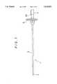
- FIG. 1is an external appearance of the blood vessel piercing instrument of this invention.
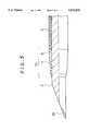
- FIG. 2is a part-sectional enlarged view of the front end portion of the blood vessel piercing instrument of an embodiment of the piercing instrument of this invention.
- FIG. 3is a part-sectional enlarged view of the front end portion of the blood vessel piercing instrument of another embodiment of this invention.
- FIG. 4is a part-sectional enlarged view of the front end portion of the blood vessel piercing instrument of another embodiment of this invention.
- FIG. 5is a part-sectional enlarged view of the front end portion of the blood vessel piercing instrument of another embodiment of this invention.
- FIG. 6is a part-sectional enlarged view of the rear end portion of the blood vessel piercing instrument of an embodiment of this invention.
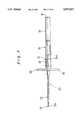
- FIG. 7is a part-sectional view of the middle to rear end portion of the blood vessel piercing instrument of another embodiment of this invention.
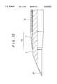
- FIG. 8is a part-sectional enlarged view of the front end portion of the blood vessel piercing instrument of another embodiment of this invention.
- FIG. 9is a part-sectional enlarged view of the front end portion of the blood vessel piercing instrument of another embodiment of this invention.
- FIG. 10is a part-sectional enlarged view of the front end portion of the blood vessel piercing instrument of another embodiment of this invention.
- FIG. 11is a part-sectional enlarged view of the front end portion of a typical conventional blood vessel piercing instrument.
- the blood vessel piercing instrument of this inventionis described below using the embodiment shown in FIGS. 1 and 2.
- the blood vessel piercing instrument 1comprises an outer tube assembly and an inner needle assembly.
- the outer tube assemblycomprises an outer tube 3 and an outer tube hub 5 attached to the rear end portion of the outer tube 3.
- the inner needle assemblycomprises a hollow inner needle 2 which is extractably inserted in the outer tube assembly and has a piercing edged surface 2a formed at the front end protruding from the outer tube 3 and an inner needle hub 4 which is attached to the rear end portion of the inner needle 2 and engages with the rear end of the outer tube hub 5.
- the outer tube 3comprises a tubular member 6 made of a superelastic or pseudoelastic metal and a resin tubular member 7 which covers the outside surface of the metal tubular member 6 and has the front end portion extending beyond the front end of the metal tubular member 6.
- the inside diameter of the front end portion of the resin tubular member 7is smaller than that of the metal tubular member 6 and substantially or approximately equal to the outside diameter of the inner needle 2.
- the inner needle assemblycomprises an inner needle 2 and an inner needle hub 4 attached to the inner needle 2 as shown in FIG. 1.
- the inner needle 2has a piercing edged surface 2a formed at the front end and has such a length that it extends through the outer tube 3 and the edged surface 2a protrudes from the front end of the outer tube 3.
- a solid needleis used for the inner needle 2.
- stainless steelis preferable.
- the front end portion of the inner needle hub 4has preferably a form which can engage with the rear end portion of the outer tube hub 5.
- the inner needle hub 4 and the outer tube hub 5are preferably provided with a securing mechanism for stopping the turning movement of the inner assembly and fixing the position of the tip of the piercing edged surface 2a.
- the inner needle hub 4has a projection 4a extending frontward from its front end as shown in FIG. 6 and the outer tube hub 5 has a groove on its rear end portion which receives the projection 4a.
- These projection 4a and the grooveform the securing mechanism.
- thermoplastic resinspolypropylene, polyethylene, polycarbonate, polystyrene, etc.
- metalsstainless steel, for example
- the joining of the inner needle 2 and inner needle hub 4may be made by means of an adhesive or solvent.
- the inner needle 2 and inner needle hub 4may also be attached by induction heating the inner needle 2 and fusing the hub 4 by the heat of the inner needle 2.
- the outer tube assemblycomprises an outer tube 3 and an outer hub 5 attached to the rear end portion of the outer tube 3.
- the outer tube 3is open at the front end to allow the front end of the inner needle 2 to protrude, as shown in FIG. 1.
- the outer tube 3consists of a metal tubular member 6 made of a superelastic metal and a resin tubular member 7 which covers the outside surface of the metal tubular member 6 as show in FIG. 2.
- the front end portion of the resin tubular member 7extends beyond the front end of the metal tubular member 6.
- the outside diameter of the front end portion 7a(the portion extending beyond the front end of the metal tubular member 6) becomes gradually smaller toward the front end, and that of the front end becomes steeply smaller.
- the inside diameter of this front end portion 7ais approximately equal to or a little larger or smaller than the outside diameter of the inner needle 2 so that a step or gap is not formed between the outside surface of the inner needle 2 and the tip of the resin tubular member 7.
- this blood vessel piercing instrument 1causes less pain to the patient when it is thrust into the blood vessel.
- the front end portion of the outer tube 3is formed of a soft resin, the possibility that the front end of the outer tube 3 may hurt the wall of the blood vessel when the inner needle 2 is pulled off and a guide wire is inserted significantly diminishes.
- the front end portion made of a soft resinelastically deforms to accommodate its shape to the wire inserted, insertion of a guide wire is made easier than when the front end portion of the outer tube 3 is made of a metal.
- annular depression 8 or an annular groovebetween the front end of the metal tubular member 6 and the inside surface of the front end portion 7a of the resin tubular member 7.
- annular depression 8By forming such an annular depression 8, the elastic bending of the resin tubular member 7 is made easier.
- the inside surface of the front end of the metal tubular member 6is so formed that the inside diameter becomes larger toward the front end, by cutting away the inside edge of the front end.
- the inside surface of the resin tubular member 7 opposite the front end of the metal tubular member 6, on the other hand,is so formed that the inside diameter becomes steeply smaller from around the front end of the metal tubular member 6 toward the front end.
- the outer tube 3 having such an annular depression 8is made by first placing a half-formed resin tubular member over the metal tubular member 6 with its front end portion extended from the front end of the metal tubular member 6 and then hot forming the half-made resin tubular member into the inside shape as shown in FIG. 2 by means of a metal mold. It can also be made by first forming the resin tubular member 7 with the inside shape as shown in FIG. 2 and then inserting the metal tubular member 6 into the resin tubular member 7.
- the outer tube 3can be attached to the outer tube hub 5 by means of an adhesive or by induction heating as mentioned above.
- the entire inside surface of the front end portion 7a of the resin tubular member 7has a substantially uniform diameter and is in contact with the outside surface of the inner needle 2
- the front end portion 7amay also be in such a form that only the inside surface of its short front end portion is in contact with the outside surface of the inner needle 2.
- the front end portion of the outer tube 3may also be formed as shown in FIG. 3.
- the outside diameter of the front end portion of the metal tubular member 6becomes smaller toward the front end.
- the resin tubular member 7it is preferable to form the resin tubular member 7 so that the outside diameter of its front end portion 7a extending beyond the front end of the metal tubular member 6 and the portion around the tapered portion of the metal tubular member 6 (that is, the portion contained in the front end portion 3a of the outer tube 3) becomes gradually smaller toward the front end, as shown in FIG. 3.
- the blood vessel piercing instrument of this embodimentalso preferably has an annular depression 8 between the front end of the metal tubular member 6 and the inside surface of the front end portion 7a of the resin tubular member 7 similar to that of the embodiment in FIG. 2.
- the inside edge of the front end of the metal tubular member 6is not cut away, and the entire front end surface of the metal tubular member 6 is a plane perpendicular to the center axis.
- the inside surface of the resin tubular member 7 opposite the front end of the metal tubular member 6is so formed that its inside diameter becomes steeply smaller from around the front end of the metal tubular member 6 toward the front end, as in the embodiment of FIG. 2.
- the annular depression 8 of the embodiment of FIG. 3thus has a cross section in the shape of a wedge that becomes thinner frontward.
- the front end portion of the blood vessel piercing instrument of the present inventionmay also be formed as shown in FIG. 4.
- the blood vessel piercing instrument of this embodimentdoes not have an annular depression as described above.
- the metal tubular member 6is so formed that the outside diameter of its front end portion becomes gradually smaller toward the front end
- the resin tubular member 7is so formed that its front end portion 7a extending beyond the front end of the metal tubular member 6 and the portion around the tapered portion of the metal tubular member 6 (that is, the portion contained in the front end portion 3a of the outer tube 3) becomes gradually smaller toward the front end.
- the outer tube 3 having such an annular depression 8is made by placing a half-formed resin tubular member over the metal tubular member 6 or inserting a mandrel through the metal tubular member 6 and dipping the metal tubular member 6 and mandrel in a solution of a resin used as the material of the resin tubular member 7 to form a resin tubular member and then hot forming the front end portion of the resin tubular member by means of a metal mold. It can also be made by first forming the resin tubular member 7 with the inside shape as shown in FIG. 4 by means of a metal mold and then inserting the metal tubular member 6 into the resin tubular member 7.
- the front end portion of the blood vessel piercing instrument of the present inventionmay also be formed as shown in FIG. 5.
- the metal tubular member 6is so formed that the inside diameter of its front end becomes larger toward the front end, and an annular depression 8 is formed between the inclined inside surface of the front end of the metal tubular member 6 and the inside surface of the front end portion 7a of the resin tubular member 7.
- the metal tubular member 6 in the embodiment of FIG. 5has the inside surface formed in the shape as described above by cutting away the inside edge of the front end in the same manner as in the embodiment of FIG. 2.
- the inside surface of the resin tubular member 7 opposite the front end surface of the metal tubular member 6, which may be spaced from or in contact with the front end surface of the metal tubular member 6,is a plane perpendicular to the center axis.
- the annular depression 8 of the embodiment of FIG. 5thus has a cross section in the shape of a wedge that becomes thinner rearward.
- the front end portion of the blood vessel piercing instrument of the present inventionmay also be formed as shown in FIG. 10.
- the blood vessel piercing instrument of this embodimentdoes not have an annular depression as those of the embodiments described above.
- the resin tubular member 7is so formed that its front end portion 7a becomes gradually smaller toward the front end.
- the metal tubular member 6 of the embodiment of FIG. 10has the front end formed so that the inside diameter becomes larger frontward by cutting away the inside edge of the front end.
- the resin tubular member 7has an annular depression to receive the front end of the metal tubular member 6 in its inside surface opposite the front end of the metal tubular member 6 formed by extending the inner portion of the surface rearward into the space between the inside surface of the metal tubular member 6 and the outside surface of the inner needle 2.
- the outer tube 3 of this structurecan be made by placing a half-formed resin tubular member over the metal tubular member 6 or inserting a mandrel through the metal tubular member 6 and dipping the metal tubular member 6 and mandrel in a solution of a resin used as the material of the resin tubular member 7 to form a resin tubular member and then hot forming the front end portion of the resin tubular member by means of a metal mold. It can also be made by first forming the resin tubular member 7 with the inside shape as shown in FIG. 10 by means of a metal mold and then inserting the metal tubular member 6 into the resin tubular member 7.
- the outer tube 3 of this structurecan be made by placing a half-formed resin tubular member over the metal tubular member 6 or inserting a mandrel through the metal tubular member 6 and dipping the metal tubular member 6 and mandrel in a solution of a resin used as the material of the resin tubular member 7 to form a resin tubular member and then hot forming the front end portion of the resin tubular member by means of a metal mold. It can also be made by first forming the resin tubular member 7 with the inside shape as shown in FIG. 10 by means of a metal mold and then inserting the metal tubular member 6 into the resin tubular member 7.
- the resin tubular member 7is preferably made of a fluororesin such as ETFE (ethylene-tetrafluoroethylene), PTFE(polytetrafluoroethylene), FEP(fluoroethylene-propylene) or PFA (polyfluoroacrylate) or an olefinic resin such as polypropylene or polyethylene and has a certain flexibility.
- the outside diameter of the outer tube 3is usually within a range of 0.9 to 2.0 mm.
- the front end portion 7a of the resin tubular member 7 extended beyond the front end of the metal tubular member 6is preferably within 0.5 to 25.0 mm.
- the material for the resin tubular member 7may contain a substance opaque to X rays of 2 ⁇ 30 w % of the resin (barium sulfate or bismuth hypocarbonate, for example). Further, it is preferable to coat the outside surface of the outer tube 3 (the outside surface of the resin tubular member 7) with a lubricating substance (silicone, for example). It is also preferable to coat the outside surface of the inner needle 2 with a lubricating substance (silicone or fluororesin such as ETFE, PTFE, FEP, PFA) in order to reduce the frictional resistance between the outside surface of the inner needle 2 and the inside surface of the outer tube 3, especially the inside surface of the resin tubular member 7.
- a lubricating substancesilicone or fluororesin such as ETFE, PTFE, FEP, PFA
- superelastic or pseudoelastic alloysare preferable.
- Superelastic alloyshere refer to those alloys generally called shape-memory alloys which show a superelasticity at the body temperature (about 37° C.) at the highest.
- superelasticityit is meant that when an alloy is deformed (bent, stretched or compressed) at service temperature to the extent where conventional metals undergo plastic deformation and the released from deformation, the alloy resumes the original shape without a need for heating.
- the Ti-Ni alloyis especially preferable.
- Mechanical propertiesmay be properly controlled by replacing part of Ti-Ni alloy by 0.01 to 10.0 atom % of X to form Ti-Ni-X alloys wherein X is Co, Fe, Mn, Cr, V, Al, Nb, W or B or replacing part of Ti-Ni alloy by 0.01 to 30.0 atom % of X to form Ti-Ni-X alloys wherein X is Cu, Pd or Zr and/or selecting the conditions of cold working and/or final heat treatment.
- the metal tubular member 6When the metal tubular member 6 is made of such a superelastic metal, the metal tubular member 6 has an appropriate rigidity at its basal (rear end) portion and becomes more flexible toward the front end. By thus forming the metal tubular member 6, the function of the blood vessel piercing instrument of this invention is improved.
- the wall thickness of the metal tubular member 6is preferably within a range of 20 to 150 ⁇ m, taking account of the required rigidity and flexibility.
- the outer tube hub 5as shown in FIG. 6, has a bore which allows the inner needle 2 to be passed through into the outer tube 3 and the rear end formed so that it can engage with the inner needle hub 4 described above.
- the outer tube hub 5has a flange-like grasp 5a formed at the middle part of its length for holding the blood vessel piercing instrument 1 when the instrument 1 is thrust into the blood vessel.
- the boreis formed in a larger diameter in the front end portion of the outer tube hub 5 and the front end portion of the bore is formed in the shape of a funnel to receive and hold the rear end of the outer tube 3.
- the resin tubular member 7 of the outer tube 3has a flange 7b formed at the rear end, and the rear end of the metal tubular member 6 protrudes beyond the rear end of the resin tubular member 7, as shown in FIG. 6.
- the rear ends of the metal tubular member 6 and resin tubular member. 7are inserted in the bore and bonded to the outer tube hub 5 by means of an adhesive 11 filled in the gap between the tubes 6 and 7 and the outer tube hub 5.
- the outer tube 3may also be attached to the outer tube hub 5 by stacking using a short metal tubular member inserted into the outer tube 3 from the rear end.
- the blood vessel piercing instrument 20 of this inventionis different from the blood vessel piercing instrument 1 of the above embodiment in that the inner needle of this embodiment is made of a hollow member.
- the blood vessel piercing instrument 20comprises an outer tube assembly consisting of an outer tube 23 and an outer tube hub 25 attached to the rear end portion of the outer tube 23 and an inner needle assembly consisting of a hollow inner needle 22 which is extractably inserted in the outer tube assembly and has a piercing edged surface 22a formed at the front end protruding from the outer tube 23 and an inner needle hub 24 which is attached to the rear end portion of the inner needle 22 and engages with the rear end of the outer tube hub 25.
- the outer tube hub 25has a tubular member 31 attached to the rear end portion.
- An elastic valve member 32is provided between the bore of the outer tube hub 25 and the tubular member 31 to allow a guide wire and catheter to be inserted through it in the liquid tight fashion and close the bore of the outer tube hub 25 when neither a guide wire nor a catheter is inserted.
- the outer tube 23, as shown in FIG. 8,consists of a metal tubular member 26 made of a superelastic metal and a resin tubular member 27 which covers the outside surface of the metal tubular member 26 and has the front end portion extending beyond the front end of the metal tubular member 26.
- the inside diameter of the front end portion of the resin tubular member 27is smaller than the inside diameter of the metal tubular member 26 and approximately equal to the outside diameter of the inner needle 22.
- the inner needle assemblycomprises an inner needle 22, an inner needle hub 24 attached to the rear end of the inner needle 22, and a cap 33 detachably attached to the rear end of the inner needle hub 24 as shown in FIG. 7.
- the inner needle 22has a piercing edged surface 22a formed at the front and has such a length that it extends through the outer tube 23 and the edged surface 22a protrudes from the front end of the outer tube 23.
- a hollow needleis used for the inner needle 22.
- a basic difference between the blood vessel piercing instrument 20 of this embodiment and that of FIG. 1is in that a hollow inner needle is used in this embodiment.
- the front end portion of the inner needle hub 24is formed in a shape which fits to the rear end portion of a tubular member 31 attached to the rear end portion of the outer tube hub 25.
- the cap 33has a filter 34 which allows air to pass but does not pass blood provided at the rear end.
- a projection 24awhich serves as a securing mechanism for stopping the turning movement of the inner assembly and fixing the position of the tip of the piercing edged surface 22a, is provided on the front end of the inner needle hub 24.
- the inner needle hub 24 and the cap 33have preferably such a degree of transparency that the flashback of blood (inflow of blood into the inner needle hub) can be viewed through them.
- thermoplastic resinssuch as polypropylene, polyethylene, polycarbonate, and polystyrene can be used. Among these resins, those having a certain degree of transparency are preferable.
- the inner needle 22 and the inner needle hub 24may be attached by means of an adhesive or a solvent, or by heating the inner needle 22 by electromagnetic induction and fusing the inner needle hub 24 made of a thermoplastic resin.
- the outer tube assemblycomprises an outer tube 23 inserted into the blood vessel and an outer tube hub 25 attached to the rear end portion of the outer tube 23.
- the outer tube 23is open at the front end with a diameter which allows the front end (piercing head) of the inner needle 22 to protrude, as shown in FIGS. 7 and 8.
- the outer tube 23consists of a metal tubular member 26 made of a superelastic metal and a resin tubular member 27 covering the outside surface of the metal tube 26, as shown in FIG. 8. The front end portion of the resin tubular member 27 extends beyond the front end of the metal tubular member 26.
- the outside diameter of the front end portion 27a of the resin tubular member 27(more specifically the portion extending beyond the front end of the metal tubular member 26) becomes gradually smaller toward the front end and that of the short front end portion becomes steeply smaller to the front end.
- the inside diameter of the front end portion 27ais equal to or a little larger or smaller than the outside diameter of the inner needle 22 so that a step or gap is not formed between the outside surface of the inner needle 22 and the front end of the resin tubular member 27.
- this blood vessel piercing instrument 20causes less pain to the patient when it is thrust into the blood vessel.
- the front end portion of the outer tube 23is formed of a soft resin, the possibility that the front end of the outer tube 23 may hurt the wall of the blood vessel when the inner needle 22 is pulled off and a guide wire is inserted significantly diminishes.
- the front end portion made of a soft resinelastically deforms to accommodate its shape to the wire inserted, insertion of a guide wire is made easier than when the front end portion of the outer tube 23 is made of a metal.
- annular depression 28between the front end of the metal tubular member 26 and the inside surface of the front end portion 27a of the resin tubular member 27.
- the outer tube 23 having such an annular depression 28can be made by the method described above.
- the entire inside surface of the front end portion 27a of the resin tubular member 27has a substantially uniform diameter and is in contact with the outside surface of the inner needle 22, the front end portion 27a may also be in such a form that only the inside surface of its short front end portion is in contact with the outside surface of the inner needle 22.
- the front end portion of the outer tube 23may also be formed as shown in FIG. 9.
- the outside diameter of the front end portion of the metal tubular member 26becomes smaller toward the front end.
- the resin tubular member 27it is preferable to form the resin tubular member 27 so that the outside diameter of its front end portion 27a extending beyond the front end of the metal tubular member 26 and the portion around the tapered portion of the metal tubular member 26 (that is, the portion contained in the front end portion 23a of the outer tube 23) becomes gradually smaller toward the front end, as shown in FIG. 9.
- the blood vessel piercing instrument 20 of this embodimentalso has an annular depression 28 between the front end of the metal tubular member 26 and the inside surface of the front end portion 27a of the resin tubular member 27 similar to that of the embodiment in FIG. 8.
- the blood vessel piercing instrument 20 of this embodimentmay also has the structures of the front end portion as shown in FIGS. 4, 5 and 10.
- the resin tubular member 27is preferably made of a fluororesin such as ETFE, PTFEP, FEP or PFA or an olefinic resin such as polypropylene or polyethylene and has a certain flexibility.
- the outside diameter of the outer tube 23is usually within a range of 0.9 to 2.0 mm.
- the front end portion of the resin tubular member 27 extended beyond the front end of the metal tubular member 26is preferably 0.5 to 25.0 mm.
- the material for the resin tubular member 27may contain a substance opaque to X rays of 2 ⁇ 30 w % of the resin (barium sulfate or bismuth hypocarbonate, for example).
- a lubricating substancesilicon, for example. It is also preferable to coat the outside surface of the inner needle 22 with a lubricating substance (silicone or fluororesin such as ETFE, PTFE, FEP, PFA) in order to reduce the frictional resistance between the outside surface of the inner needle 22 and the inside surface of the outer tube 23, especially the inside surface of the resin tubular member 27.
- the Ti-Ni alloyis especially preferable.
- Mechanical propertiesmay be properly controlled by replacing part of Ti-Ni alloy by 0.01 to 10.0 atom % of X to form Ti-Ni-X alloys wherein X is Co, Fe, Mn, Cr, V, Al, Nb, W or B or replacing part of Ti-Ni alloy by 0.01 to 30.0 atom % of X to form Ti-Ni-X alloys wherein X is Cu, Pd or Zr and/or selecting the conditions of cold working and/or final heat treatment.
- the metal tubular member 26is made of such a superelastic or pseudoelastic metal, it preferably has an appropriate rigidity at its basal (rear end) portion and becomes more flexible toward the front end.
- the outer tube hub 25has a tubular member 31 attached to its rear end portion.
- the tubular member 31is provided inside it with an elastic valve member 32 which openably closes part of the cross section of the bore of the outer tube hub 25.
- the valve member 32has a disk-like shape and an openable part for allowing the inner needle 22 and a guide wire to be inserted through in a liquid-tight fashion. This openable part closes when neither the inner needle 22 nor a guide wire is inserted, preventing the blood from flowing out.
- a disk-shaped membermade of a soft material such as silicone rubber, butadiene rubber, or styrene-elastomer (SBS elastomer, SEBS elastomer, for example) is preferable.
- the openable part of the valve member 32can be formed by making incisions such as so called Y cut or crucial (+) cut in the valve member.
- An openable part formed by first and second incisions on each side of the valve member which do not reach the other side and intercross at the center of the valve memberis preferable.
- thermoplastic resinssuch as polypropylene, polyethylene, polycarbonate, and polystyrene can be used. Especially those of them having a certain degree of transparency are preferable.
- the inner needle 22 and the inner needle hub 25can be attached by the same methods as described above.
- the inner needle 2is inserted in the outer tube 3 from the rear end of the outer tube hub 5 before use, as shown in FIG. 1.
- the piercing edged surface 2a of the inner needle 2protrudes from the front end of the outer tube 3 and the blood vessel piercing instrument 1 is ready to be thrust into blood vessel.
- the blood vessel piercing instrument 1 in this stateis grasped at the outer tube hub 5 and thrust into the blood vessel.
- the inner needle assemblyis then pulled off from the outer tube assembly. This makes it possible for the blood to flow out through the inside of the outer tube 3, and it is ascertained by the blood flowing out that the front end of the outer tube 3 is in the blood vessel.
- a guide wireis inserted into the blood vessel through the outer tube 3.
- the outer tube 3is removed and then a catheter such as blood vessel dilatation catheter or catheter for the roentogenographic visualization of the blood vessels is slid on the guide wire and inserted into the blood vessel.
- the blood vessel piercing instrument of this inventionAs described above, neither a step nor gap is formed between the outside surface of the inner needle and the tip of the outer tube (the resin tubular member). Because of this structure, the blood vessel piercing instrument of this invention causes less pain to the patient when it is thrust into the blood vessel.
- the front end portion of the outer tubeis formed of a soft resin. This significantly reduces the possibility that the front end of the outer tube may hurt the wall of the blood vessel after the inner needle is removed and when a guide wire is inserted significantly diminishes.
- the front end portion of the outer tubeis made of a soft resin and elastically deforms to accommodate its shape to a guide wire inserted.
- the metal tubular member of the outer tube made of a superelastic metalhas a high strength and elasticity and therefore the entire outer tube can bend smoothly. These makes easier the insertion of a guide wire and prevents the outer tube from bending in angles after the inner needle is removed or when a guide wire is inserted.
Landscapes
- Health & Medical Sciences (AREA)
- Life Sciences & Earth Sciences (AREA)
- Hematology (AREA)
- Animal Behavior & Ethology (AREA)
- Engineering & Computer Science (AREA)
- Anesthesiology (AREA)
- Biomedical Technology (AREA)
- Heart & Thoracic Surgery (AREA)
- Biophysics (AREA)
- Pulmonology (AREA)
- General Health & Medical Sciences (AREA)
- Public Health (AREA)
- Veterinary Medicine (AREA)
- Media Introduction/Drainage Providing Device (AREA)
- Infusion, Injection, And Reservoir Apparatuses (AREA)
- Surgical Instruments (AREA)
Abstract
Description
Claims (6)
Applications Claiming Priority (2)
| Application Number | Priority Date | Filing Date | Title |
|---|---|---|---|
| JP5031474AJPH06217988A (en) | 1993-01-26 | 1993-01-26 | Blood vessel sticking instrument |
| JP5-031474 | 1993-01-26 |
Publications (1)
| Publication Number | Publication Date |
|---|---|
| US5522832Atrue US5522832A (en) | 1996-06-04 |
Family
ID=12332268
Family Applications (1)
| Application Number | Title | Priority Date | Filing Date |
|---|---|---|---|
| US08/186,594Expired - LifetimeUS5522832A (en) | 1993-01-26 | 1994-01-26 | Blood vessel piercing instrument |
Country Status (4)
| Country | Link |
|---|---|
| US (1) | US5522832A (en) |
| EP (1) | EP0608854B1 (en) |
| JP (1) | JPH06217988A (en) |
| DE (1) | DE69419627T2 (en) |
Cited By (119)
| Publication number | Priority date | Publication date | Assignee | Title |
|---|---|---|---|---|
| US5782811A (en)* | 1996-05-30 | 1998-07-21 | Target Therapeutics, Inc. | Kink-resistant braided catheter with distal side holes |
| US6042578A (en)* | 1996-05-13 | 2000-03-28 | Schneider (Usa) Inc. | Catheter reinforcing braids |
| US6159225A (en)* | 1995-10-13 | 2000-12-12 | Transvascular, Inc. | Device for interstitial transvascular intervention and revascularization |
| US6190353B1 (en) | 1995-10-13 | 2001-02-20 | Transvascular, Inc. | Methods and apparatus for bypassing arterial obstructions and/or performing other transvascular procedures |
| WO2002036042A3 (en)* | 2000-11-06 | 2003-05-22 | Sterling Medivations Inc | Subcutaneous injection set tubing with solvent bonding |
| US20040030302A1 (en)* | 2001-03-28 | 2004-02-12 | Miyako Kamata | Medical syringe, and method of producing the same |
| US20050015114A1 (en)* | 2001-05-07 | 2005-01-20 | Eugen Seibold | Piercing article and intermediate product for manufacturing such a piercing article |
| US20080147010A1 (en)* | 2006-12-18 | 2008-06-19 | Hiroaki Nakajima | Indwelling needle assembly |
| US20080243065A1 (en)* | 2007-03-29 | 2008-10-02 | Dan Rottenberg | Lumen reentry devices and methods |
| US20100094259A1 (en)* | 1995-10-13 | 2010-04-15 | Medtronic Vascular, Inc. | Catheters and Related Devices for Forming Passageways Between Blood Vessels or Other Anatomical Structures |
| US20100121357A1 (en)* | 1995-10-13 | 2010-05-13 | Medtronic Vascular, Inc. | Tissue Penetrating Catheters having Integral Imaging Transducers and Their Methods of Use |
| CN1945337B (en)* | 2005-10-03 | 2012-01-04 | 希森美康株式会社 | Specimen analyzer |
| USD714934S1 (en)* | 2012-12-19 | 2014-10-07 | Daikyo Seiko, Ltd. | Plunger rod |
| USD714933S1 (en)* | 2012-12-19 | 2014-10-07 | Daikyo Seiko, Ltd. | Plunger rod |
| USD717429S1 (en)* | 2012-12-19 | 2014-11-11 | Daikyo Seiko, Ltd. | Plunger rod |
| US10441308B2 (en) | 2007-11-30 | 2019-10-15 | Ethicon Llc | Ultrasonic surgical instrument blades |
| US10463887B2 (en) | 2007-11-30 | 2019-11-05 | Ethicon Llc | Ultrasonic surgical blades |
| US10517627B2 (en) | 2012-04-09 | 2019-12-31 | Ethicon Llc | Switch arrangements for ultrasonic surgical instruments |
| US10531910B2 (en) | 2007-07-27 | 2020-01-14 | Ethicon Llc | Surgical instruments |
| US10537352B2 (en) | 2004-10-08 | 2020-01-21 | Ethicon Llc | Tissue pads for use with surgical instruments |
| US10575892B2 (en) | 2015-12-31 | 2020-03-03 | Ethicon Llc | Adapter for electrical surgical instruments |
| US10595929B2 (en) | 2015-03-24 | 2020-03-24 | Ethicon Llc | Surgical instruments with firing system overload protection mechanisms |
| US10603064B2 (en) | 2016-11-28 | 2020-03-31 | Ethicon Llc | Ultrasonic transducer |
| US10610286B2 (en) | 2015-09-30 | 2020-04-07 | Ethicon Llc | Techniques for circuit topologies for combined generator |
| US10639092B2 (en) | 2014-12-08 | 2020-05-05 | Ethicon Llc | Electrode configurations for surgical instruments |
| US10646269B2 (en) | 2016-04-29 | 2020-05-12 | Ethicon Llc | Non-linear jaw gap for electrosurgical instruments |
| US10688321B2 (en) | 2009-07-15 | 2020-06-23 | Ethicon Llc | Ultrasonic surgical instruments |
| US10709906B2 (en) | 2009-05-20 | 2020-07-14 | Ethicon Llc | Coupling arrangements and methods for attaching tools to ultrasonic surgical instruments |
| US10709469B2 (en) | 2016-01-15 | 2020-07-14 | Ethicon Llc | Modular battery powered handheld surgical instrument with energy conservation techniques |
| US10716615B2 (en) | 2016-01-15 | 2020-07-21 | Ethicon Llc | Modular battery powered handheld surgical instrument with curved end effectors having asymmetric engagement between jaw and blade |
| US10722261B2 (en) | 2007-03-22 | 2020-07-28 | Ethicon Llc | Surgical instruments |
| US10729494B2 (en) | 2012-02-10 | 2020-08-04 | Ethicon Llc | Robotically controlled surgical instrument |
| US10744304B2 (en) | 2009-08-28 | 2020-08-18 | Boston Scientific Limited | Inverted balloon neck on catheter |
| US10765470B2 (en) | 2015-06-30 | 2020-09-08 | Ethicon Llc | Surgical system with user adaptable techniques employing simultaneous energy modalities based on tissue parameters |
| US10779879B2 (en) | 2014-03-18 | 2020-09-22 | Ethicon Llc | Detecting short circuits in electrosurgical medical devices |
| US10779848B2 (en) | 2006-01-20 | 2020-09-22 | Ethicon Llc | Ultrasound medical instrument having a medical ultrasonic blade |
| US10779845B2 (en) | 2012-06-29 | 2020-09-22 | Ethicon Llc | Ultrasonic surgical instruments with distally positioned transducers |
| US10779847B2 (en) | 2016-08-25 | 2020-09-22 | Ethicon Llc | Ultrasonic transducer to waveguide joining |
| US10820920B2 (en) | 2017-07-05 | 2020-11-03 | Ethicon Llc | Reusable ultrasonic medical devices and methods of their use |
| US10828057B2 (en) | 2007-03-22 | 2020-11-10 | Ethicon Llc | Ultrasonic surgical instruments |
| US10828059B2 (en) | 2007-10-05 | 2020-11-10 | Ethicon Llc | Ergonomic surgical instruments |
| US10835768B2 (en) | 2010-02-11 | 2020-11-17 | Ethicon Llc | Dual purpose surgical instrument for cutting and coagulating tissue |
| US10835307B2 (en) | 2001-06-12 | 2020-11-17 | Ethicon Llc | Modular battery powered handheld surgical instrument containing elongated multi-layered shaft |
| US10842580B2 (en) | 2012-06-29 | 2020-11-24 | Ethicon Llc | Ultrasonic surgical instruments with control mechanisms |
| US10856929B2 (en) | 2014-01-07 | 2020-12-08 | Ethicon Llc | Harvesting energy from a surgical generator |
| US10856896B2 (en) | 2005-10-14 | 2020-12-08 | Ethicon Llc | Ultrasonic device for cutting and coagulating |
| US10874418B2 (en) | 2004-02-27 | 2020-12-29 | Ethicon Llc | Ultrasonic surgical shears and method for sealing a blood vessel using same |
| US10893883B2 (en) | 2016-07-13 | 2021-01-19 | Ethicon Llc | Ultrasonic assembly for use with ultrasonic surgical instruments |
| US10898256B2 (en) | 2015-06-30 | 2021-01-26 | Ethicon Llc | Surgical system with user adaptable techniques based on tissue impedance |
| US10912580B2 (en) | 2013-12-16 | 2021-02-09 | Ethicon Llc | Medical device |
| US10912603B2 (en) | 2013-11-08 | 2021-02-09 | Ethicon Llc | Electrosurgical devices |
| US10925659B2 (en) | 2013-09-13 | 2021-02-23 | Ethicon Llc | Electrosurgical (RF) medical instruments for cutting and coagulating tissue |
| US10952788B2 (en) | 2015-06-30 | 2021-03-23 | Ethicon Llc | Surgical instrument with user adaptable algorithms |
| US10952759B2 (en) | 2016-08-25 | 2021-03-23 | Ethicon Llc | Tissue loading of a surgical instrument |
| US10966747B2 (en) | 2012-06-29 | 2021-04-06 | Ethicon Llc | Haptic feedback devices for surgical robot |
| US10966744B2 (en) | 2016-07-12 | 2021-04-06 | Ethicon Llc | Ultrasonic surgical instrument with piezoelectric central lumen transducer |
| US10987123B2 (en) | 2012-06-28 | 2021-04-27 | Ethicon Llc | Surgical instruments with articulating shafts |
| US10993763B2 (en) | 2012-06-29 | 2021-05-04 | Ethicon Llc | Lockout mechanism for use with robotic electrosurgical device |
| US11020140B2 (en) | 2015-06-17 | 2021-06-01 | Cilag Gmbh International | Ultrasonic surgical blade for use with ultrasonic surgical instruments |
| US11033292B2 (en) | 2013-12-16 | 2021-06-15 | Cilag Gmbh International | Medical device |
| US11051873B2 (en) | 2015-06-30 | 2021-07-06 | Cilag Gmbh International | Surgical system with user adaptable techniques employing multiple energy modalities based on tissue parameters |
| USD924400S1 (en) | 2016-08-16 | 2021-07-06 | Cilag Gmbh International | Surgical instrument |
| US11058447B2 (en) | 2007-07-31 | 2021-07-13 | Cilag Gmbh International | Temperature controlled ultrasonic surgical instruments |
| US11065419B2 (en) | 2017-05-26 | 2021-07-20 | Piper Access, Llc | Catheter delivery devices, systems, and methods |
| US11090104B2 (en) | 2009-10-09 | 2021-08-17 | Cilag Gmbh International | Surgical generator for ultrasonic and electrosurgical devices |
| US11096752B2 (en) | 2012-06-29 | 2021-08-24 | Cilag Gmbh International | Closed feedback control for electrosurgical device |
| US11129669B2 (en) | 2015-06-30 | 2021-09-28 | Cilag Gmbh International | Surgical system with user adaptable techniques based on tissue type |
| US11129670B2 (en) | 2016-01-15 | 2021-09-28 | Cilag Gmbh International | Modular battery powered handheld surgical instrument with selective application of energy based on button displacement, intensity, or local tissue characterization |
| US11179173B2 (en) | 2012-10-22 | 2021-11-23 | Cilag Gmbh International | Surgical instrument |
| US11202670B2 (en) | 2016-02-22 | 2021-12-21 | Cilag Gmbh International | Method of manufacturing a flexible circuit electrode for electrosurgical instrument |
| US11229471B2 (en) | 2016-01-15 | 2022-01-25 | Cilag Gmbh International | Modular battery powered handheld surgical instrument with selective application of energy based on tissue characterization |
| US11266430B2 (en) | 2016-11-29 | 2022-03-08 | Cilag Gmbh International | End effector control and calibration |
| US11272952B2 (en) | 2013-03-14 | 2022-03-15 | Cilag Gmbh International | Mechanical fasteners for use with surgical energy devices |
| US11311326B2 (en) | 2015-02-06 | 2022-04-26 | Cilag Gmbh International | Electrosurgical instrument with rotation and articulation mechanisms |
| US11324527B2 (en) | 2012-11-15 | 2022-05-10 | Cilag Gmbh International | Ultrasonic and electrosurgical devices |
| US11337747B2 (en) | 2014-04-15 | 2022-05-24 | Cilag Gmbh International | Software algorithms for electrosurgical instruments |
| US11344362B2 (en) | 2016-08-05 | 2022-05-31 | Cilag Gmbh International | Methods and systems for advanced harmonic energy |
| US11369402B2 (en) | 2010-02-11 | 2022-06-28 | Cilag Gmbh International | Control systems for ultrasonically powered surgical instruments |
| US11382642B2 (en) | 2010-02-11 | 2022-07-12 | Cilag Gmbh International | Rotatable cutting implements with friction reducing material for ultrasonic surgical instruments |
| US11399855B2 (en) | 2014-03-27 | 2022-08-02 | Cilag Gmbh International | Electrosurgical devices |
| US11413060B2 (en) | 2014-07-31 | 2022-08-16 | Cilag Gmbh International | Actuation mechanisms and load adjustment assemblies for surgical instruments |
| US11426191B2 (en) | 2012-06-29 | 2022-08-30 | Cilag Gmbh International | Ultrasonic surgical instruments with distally positioned jaw assemblies |
| US11452525B2 (en) | 2019-12-30 | 2022-09-27 | Cilag Gmbh International | Surgical instrument comprising an adjustment system |
| US11471209B2 (en) | 2014-03-31 | 2022-10-18 | Cilag Gmbh International | Controlling impedance rise in electrosurgical medical devices |
| US11553954B2 (en) | 2015-06-30 | 2023-01-17 | Cilag Gmbh International | Translatable outer tube for sealing using shielded lap chole dissector |
| US11583306B2 (en) | 2012-06-29 | 2023-02-21 | Cilag Gmbh International | Surgical instruments with articulating shafts |
| US11589916B2 (en) | 2019-12-30 | 2023-02-28 | Cilag Gmbh International | Electrosurgical instruments with electrodes having variable energy densities |
| US11660089B2 (en) | 2019-12-30 | 2023-05-30 | Cilag Gmbh International | Surgical instrument comprising a sensing system |
| US11666375B2 (en) | 2015-10-16 | 2023-06-06 | Cilag Gmbh International | Electrode wiping surgical device |
| US11666784B2 (en) | 2007-07-31 | 2023-06-06 | Cilag Gmbh International | Surgical instruments |
| US11684412B2 (en) | 2019-12-30 | 2023-06-27 | Cilag Gmbh International | Surgical instrument with rotatable and articulatable surgical end effector |
| US11690641B2 (en) | 2007-07-27 | 2023-07-04 | Cilag Gmbh International | Ultrasonic end effectors with increased active length |
| US11696776B2 (en) | 2019-12-30 | 2023-07-11 | Cilag Gmbh International | Articulatable surgical instrument |
| US11723716B2 (en) | 2019-12-30 | 2023-08-15 | Cilag Gmbh International | Electrosurgical instrument with variable control mechanisms |
| US11759251B2 (en) | 2019-12-30 | 2023-09-19 | Cilag Gmbh International | Control program adaptation based on device status and user input |
| US11779387B2 (en) | 2019-12-30 | 2023-10-10 | Cilag Gmbh International | Clamp arm jaw to minimize tissue sticking and improve tissue control |
| US11779329B2 (en) | 2019-12-30 | 2023-10-10 | Cilag Gmbh International | Surgical instrument comprising a flex circuit including a sensor system |
| US11786291B2 (en) | 2019-12-30 | 2023-10-17 | Cilag Gmbh International | Deflectable support of RF energy electrode with respect to opposing ultrasonic blade |
| US11812957B2 (en) | 2019-12-30 | 2023-11-14 | Cilag Gmbh International | Surgical instrument comprising a signal interference resolution system |
| US11864820B2 (en) | 2016-05-03 | 2024-01-09 | Cilag Gmbh International | Medical device with a bilateral jaw configuration for nerve stimulation |
| US11871955B2 (en) | 2012-06-29 | 2024-01-16 | Cilag Gmbh International | Surgical instruments with articulating shafts |
| US11877734B2 (en) | 2007-07-31 | 2024-01-23 | Cilag Gmbh International | Ultrasonic surgical instruments |
| US11890491B2 (en) | 2008-08-06 | 2024-02-06 | Cilag Gmbh International | Devices and techniques for cutting and coagulating tissue |
| US11911063B2 (en) | 2019-12-30 | 2024-02-27 | Cilag Gmbh International | Techniques for detecting ultrasonic blade to electrode contact and reducing power to ultrasonic blade |
| US11937866B2 (en) | 2019-12-30 | 2024-03-26 | Cilag Gmbh International | Method for an electrosurgical procedure |
| US11937863B2 (en) | 2019-12-30 | 2024-03-26 | Cilag Gmbh International | Deflectable electrode with variable compression bias along the length of the deflectable electrode |
| US11944366B2 (en) | 2019-12-30 | 2024-04-02 | Cilag Gmbh International | Asymmetric segmented ultrasonic support pad for cooperative engagement with a movable RF electrode |
| US11950797B2 (en) | 2019-12-30 | 2024-04-09 | Cilag Gmbh International | Deflectable electrode with higher distal bias relative to proximal bias |
| US11986201B2 (en) | 2019-12-30 | 2024-05-21 | Cilag Gmbh International | Method for operating a surgical instrument |
| US12023086B2 (en) | 2019-12-30 | 2024-07-02 | Cilag Gmbh International | Electrosurgical instrument for delivering blended energy modalities to tissue |
| US12053224B2 (en) | 2019-12-30 | 2024-08-06 | Cilag Gmbh International | Variation in electrode parameters and deflectable electrode to modify energy density and tissue interaction |
| US12064109B2 (en) | 2019-12-30 | 2024-08-20 | Cilag Gmbh International | Surgical instrument comprising a feedback control circuit |
| US12076006B2 (en) | 2019-12-30 | 2024-09-03 | Cilag Gmbh International | Surgical instrument comprising an orientation detection system |
| US12082808B2 (en) | 2019-12-30 | 2024-09-10 | Cilag Gmbh International | Surgical instrument comprising a control system responsive to software configurations |
| US12114912B2 (en) | 2019-12-30 | 2024-10-15 | Cilag Gmbh International | Non-biased deflectable electrode to minimize contact between ultrasonic blade and electrode |
| US12193698B2 (en) | 2016-01-15 | 2025-01-14 | Cilag Gmbh International | Method for self-diagnosing operation of a control switch in a surgical instrument system |
| US12262937B2 (en) | 2019-12-30 | 2025-04-01 | Cilag Gmbh International | User interface for surgical instrument with combination energy modality end-effector |
| US12336747B2 (en) | 2019-12-30 | 2025-06-24 | Cilag Gmbh International | Method of operating a combination ultrasonic / bipolar RF surgical device with a combination energy modality end-effector |
| US12343063B2 (en) | 2019-12-30 | 2025-07-01 | Cilag Gmbh International | Multi-layer clamp arm pad for enhanced versatility and performance of a surgical device |
Families Citing this family (33)
| Publication number | Priority date | Publication date | Assignee | Title |
|---|---|---|---|---|
| JP3375765B2 (en)* | 1994-12-27 | 2003-02-10 | マニー株式会社 | Method for manufacturing root canal treatment device and root canal treatment device |
| DE19922169B4 (en)* | 1999-05-12 | 2005-06-30 | Fraunhofer-Gesellschaft zur Förderung der angewandten Forschung e.V. | Process for separating / cutting components, workpieces and / or test specimens of any thickness, size and other dimensions from concrete, stone and other mineral building materials with economically acceptable separation speeds |
| JP2003102745A (en)* | 2001-09-28 | 2003-04-08 | Kitazato Supply:Co Ltd | Puncture needle for inserting member for medical laser irradiation, catheter for inserting member for medical laser irradiation, and medical laser generator |
| DE10324365A1 (en)* | 2003-05-27 | 2005-01-05 | Forschungszentrum Jülich GmbH | Device with a space for receiving hyperpolarized noble gas |
| WO2005072402A2 (en)* | 2004-01-29 | 2005-08-11 | Cannuflow, Inc. | Atraumatic arthroscopic instrument sheath |
| US8066729B2 (en) | 2004-03-02 | 2011-11-29 | Stryker Corporation | Surgical obturator |
| US8226675B2 (en) | 2007-03-22 | 2012-07-24 | Ethicon Endo-Surgery, Inc. | Surgical instruments |
| US8882791B2 (en) | 2007-07-27 | 2014-11-11 | Ethicon Endo-Surgery, Inc. | Ultrasonic surgical instruments |
| US9050093B2 (en) | 2009-10-09 | 2015-06-09 | Ethicon Endo-Surgery, Inc. | Surgical generator for ultrasonic and electrosurgical devices |
| US10441345B2 (en) | 2009-10-09 | 2019-10-15 | Ethicon Llc | Surgical generator for ultrasonic and electrosurgical devices |
| USRE47996E1 (en) | 2009-10-09 | 2020-05-19 | Ethicon Llc | Surgical generator for ultrasonic and electrosurgical devices |
| US9168054B2 (en) | 2009-10-09 | 2015-10-27 | Ethicon Endo-Surgery, Inc. | Surgical generator for ultrasonic and electrosurgical devices |
| US8961547B2 (en) | 2010-02-11 | 2015-02-24 | Ethicon Endo-Surgery, Inc. | Ultrasonic surgical instruments with moving cutting implement |
| US8579928B2 (en) | 2010-02-11 | 2013-11-12 | Ethicon Endo-Surgery, Inc. | Outer sheath and blade arrangements for ultrasonic surgical instruments |
| US8795327B2 (en) | 2010-07-22 | 2014-08-05 | Ethicon Endo-Surgery, Inc. | Electrosurgical instrument with separate closure and cutting members |
| US9192431B2 (en) | 2010-07-23 | 2015-11-24 | Ethicon Endo-Surgery, Inc. | Electrosurgical cutting and sealing instrument |
| US9259265B2 (en) | 2011-07-22 | 2016-02-16 | Ethicon Endo-Surgery, Llc | Surgical instruments for tensioning tissue |
| US9724118B2 (en) | 2012-04-09 | 2017-08-08 | Ethicon Endo-Surgery, Llc | Techniques for cutting and coagulating tissue for ultrasonic surgical instruments |
| US9237921B2 (en) | 2012-04-09 | 2016-01-19 | Ethicon Endo-Surgery, Inc. | Devices and techniques for cutting and coagulating tissue |
| US9283045B2 (en) | 2012-06-29 | 2016-03-15 | Ethicon Endo-Surgery, Llc | Surgical instruments with fluid management system |
| EP2900158B1 (en) | 2012-09-28 | 2020-04-15 | Ethicon LLC | Multi-function bi-polar forceps |
| US9241728B2 (en) | 2013-03-15 | 2016-01-26 | Ethicon Endo-Surgery, Inc. | Surgical instrument with multiple clamping mechanisms |
| US10463421B2 (en) | 2014-03-27 | 2019-11-05 | Ethicon Llc | Two stage trigger, clamp and cut bipolar vessel sealer |
| US10342602B2 (en) | 2015-03-17 | 2019-07-09 | Ethicon Llc | Managing tissue treatment |
| US10321950B2 (en) | 2015-03-17 | 2019-06-18 | Ethicon Llc | Managing tissue treatment |
| US10034684B2 (en) | 2015-06-15 | 2018-07-31 | Ethicon Llc | Apparatus and method for dissecting and coagulating tissue |
| US10154852B2 (en) | 2015-07-01 | 2018-12-18 | Ethicon Llc | Ultrasonic surgical blade with improved cutting and coagulation features |
| US10449332B2 (en)* | 2015-08-05 | 2019-10-22 | Biosense Webster (Israel) Ltd. | Guide wire luer hub |
| US10179022B2 (en) | 2015-12-30 | 2019-01-15 | Ethicon Llc | Jaw position impedance limiter for electrosurgical instrument |
| US10702329B2 (en) | 2016-04-29 | 2020-07-07 | Ethicon Llc | Jaw structure with distal post for electrosurgical instruments |
| US10485607B2 (en) | 2016-04-29 | 2019-11-26 | Ethicon Llc | Jaw structure with distal closure for electrosurgical instruments |
| US10842522B2 (en) | 2016-07-15 | 2020-11-24 | Ethicon Llc | Ultrasonic surgical instruments having offset blades |
| US10285723B2 (en) | 2016-08-09 | 2019-05-14 | Ethicon Llc | Ultrasonic surgical blade with improved heel portion |
Citations (8)
| Publication number | Priority date | Publication date | Assignee | Title |
|---|---|---|---|---|
| US3565074A (en)* | 1969-04-24 | 1971-02-23 | Becton Dickinson Co | Indwelling arterial cannula assembly |
| US4317445A (en)* | 1980-03-31 | 1982-03-02 | Baxter Travenol Laboratories, Inc. | Catheter insertion unit with separate flashback indication for the cannula |
| US4840622A (en)* | 1987-10-06 | 1989-06-20 | Menlo Care, Inc. | Kink resistant catheter |
| US5011478A (en)* | 1989-01-31 | 1991-04-30 | Cook Incorporation | Recessed dilator-sheath assembly and method |
| EP0437795A1 (en)* | 1989-12-20 | 1991-07-24 | Terumo Kabushiki Kaisha | Catheter having a super-elastic metallic tube body |
| US5180376A (en)* | 1990-05-01 | 1993-01-19 | Cathco, Inc. | Non-buckling thin-walled sheath for the percutaneous insertion of intraluminal catheters |
| US5263937A (en)* | 1993-02-11 | 1993-11-23 | Shipp John I | Trocar with profile to reduce insertion force |
| US5350393A (en)* | 1992-01-06 | 1994-09-27 | Inbae Yoon | Safety trocar penetrating instrument |
- 1993
- 1993-01-26JPJP5031474Apatent/JPH06217988A/enactivePending
- 1994
- 1994-01-26EPEP94101118Apatent/EP0608854B1/ennot_activeExpired - Lifetime
- 1994-01-26USUS08/186,594patent/US5522832A/ennot_activeExpired - Lifetime
- 1994-01-26DEDE69419627Tpatent/DE69419627T2/ennot_activeExpired - Fee Related
Patent Citations (8)
| Publication number | Priority date | Publication date | Assignee | Title |
|---|---|---|---|---|
| US3565074A (en)* | 1969-04-24 | 1971-02-23 | Becton Dickinson Co | Indwelling arterial cannula assembly |
| US4317445A (en)* | 1980-03-31 | 1982-03-02 | Baxter Travenol Laboratories, Inc. | Catheter insertion unit with separate flashback indication for the cannula |
| US4840622A (en)* | 1987-10-06 | 1989-06-20 | Menlo Care, Inc. | Kink resistant catheter |
| US5011478A (en)* | 1989-01-31 | 1991-04-30 | Cook Incorporation | Recessed dilator-sheath assembly and method |
| EP0437795A1 (en)* | 1989-12-20 | 1991-07-24 | Terumo Kabushiki Kaisha | Catheter having a super-elastic metallic tube body |
| US5180376A (en)* | 1990-05-01 | 1993-01-19 | Cathco, Inc. | Non-buckling thin-walled sheath for the percutaneous insertion of intraluminal catheters |
| US5350393A (en)* | 1992-01-06 | 1994-09-27 | Inbae Yoon | Safety trocar penetrating instrument |
| US5263937A (en)* | 1993-02-11 | 1993-11-23 | Shipp John I | Trocar with profile to reduce insertion force |
Cited By (195)
| Publication number | Priority date | Publication date | Assignee | Title |
|---|---|---|---|---|
| US20100121357A1 (en)* | 1995-10-13 | 2010-05-13 | Medtronic Vascular, Inc. | Tissue Penetrating Catheters having Integral Imaging Transducers and Their Methods of Use |
| US8727988B2 (en) | 1995-10-13 | 2014-05-20 | Medtronic Vascular, Inc. | Tissue penetrating catheters having integral imaging transducers and their methods of use |
| US6159225A (en)* | 1995-10-13 | 2000-12-12 | Transvascular, Inc. | Device for interstitial transvascular intervention and revascularization |
| US6190353B1 (en) | 1995-10-13 | 2001-02-20 | Transvascular, Inc. | Methods and apparatus for bypassing arterial obstructions and/or performing other transvascular procedures |
| US8753366B2 (en) | 1995-10-13 | 2014-06-17 | Medtronic Vascular, Inc. | Catheters and related devices for forming passageways between blood vessels or other anatomical structures |
| US7134438B2 (en) | 1995-10-13 | 2006-11-14 | Medtronic Vascular, Inc. | Methods and apparatus for bypassing arterial obstructions and/or performing other transvascular procedures |
| US20100094259A1 (en)* | 1995-10-13 | 2010-04-15 | Medtronic Vascular, Inc. | Catheters and Related Devices for Forming Passageways Between Blood Vessels or Other Anatomical Structures |
| US6655386B1 (en) | 1995-10-13 | 2003-12-02 | Transvascular, Inc. | Transluminal method for bypassing arterial obstructions |
| US7059330B1 (en) | 1995-10-13 | 2006-06-13 | Medtronic Vascular, Inc. | Methods and apparatus for bypassing arterial obstructions and/or performing other transvascular procedures |
| US20040059280A1 (en)* | 1995-10-13 | 2004-03-25 | Trans Vascular, Inc. | Methods and apparatus for bypassing arterial obstructions and/or performing other transvascular procedures |
| US6042578A (en)* | 1996-05-13 | 2000-03-28 | Schneider (Usa) Inc. | Catheter reinforcing braids |
| US6503353B1 (en) | 1996-05-13 | 2003-01-07 | Schneider (Usa) Inc. | Method for making a catheter |
| US6197014B1 (en) | 1996-05-30 | 2001-03-06 | Target Therapeutics, Inc. | Kink-resistant braided catheter with distal side holes |
| US5782811A (en)* | 1996-05-30 | 1998-07-21 | Target Therapeutics, Inc. | Kink-resistant braided catheter with distal side holes |
| WO2002036042A3 (en)* | 2000-11-06 | 2003-05-22 | Sterling Medivations Inc | Subcutaneous injection set tubing with solvent bonding |
| US6673440B2 (en) | 2000-11-06 | 2004-01-06 | Sterling Medivations, Inc. | Subcutaneous injection set tubing with solvent bonding |
| US20040030302A1 (en)* | 2001-03-28 | 2004-02-12 | Miyako Kamata | Medical syringe, and method of producing the same |
| US20050015114A1 (en)* | 2001-05-07 | 2005-01-20 | Eugen Seibold | Piercing article and intermediate product for manufacturing such a piercing article |
| US10835307B2 (en) | 2001-06-12 | 2020-11-17 | Ethicon Llc | Modular battery powered handheld surgical instrument containing elongated multi-layered shaft |
| US11229472B2 (en) | 2001-06-12 | 2022-01-25 | Cilag Gmbh International | Modular battery powered handheld surgical instrument with multiple magnetic position sensors |
| US11730507B2 (en) | 2004-02-27 | 2023-08-22 | Cilag Gmbh International | Ultrasonic surgical shears and method for sealing a blood vessel using same |
| US10874418B2 (en) | 2004-02-27 | 2020-12-29 | Ethicon Llc | Ultrasonic surgical shears and method for sealing a blood vessel using same |
| US10537352B2 (en) | 2004-10-08 | 2020-01-21 | Ethicon Llc | Tissue pads for use with surgical instruments |
| US11006971B2 (en) | 2004-10-08 | 2021-05-18 | Ethicon Llc | Actuation mechanism for use with an ultrasonic surgical instrument |
| CN1945337B (en)* | 2005-10-03 | 2012-01-04 | 希森美康株式会社 | Specimen analyzer |
| US11998229B2 (en) | 2005-10-14 | 2024-06-04 | Cilag Gmbh International | Ultrasonic device for cutting and coagulating |
| US10856896B2 (en) | 2005-10-14 | 2020-12-08 | Ethicon Llc | Ultrasonic device for cutting and coagulating |
| US12042168B2 (en) | 2006-01-20 | 2024-07-23 | Cilag Gmbh International | Ultrasound medical instrument having a medical ultrasonic blade |
| US10779848B2 (en) | 2006-01-20 | 2020-09-22 | Ethicon Llc | Ultrasound medical instrument having a medical ultrasonic blade |
| US8075529B2 (en)* | 2006-12-18 | 2011-12-13 | Medikit Co., Ltd. | Indwelling needle assembly |
| US20080147010A1 (en)* | 2006-12-18 | 2008-06-19 | Hiroaki Nakajima | Indwelling needle assembly |
| US10722261B2 (en) | 2007-03-22 | 2020-07-28 | Ethicon Llc | Surgical instruments |
| US10828057B2 (en) | 2007-03-22 | 2020-11-10 | Ethicon Llc | Ultrasonic surgical instruments |
| US8257382B2 (en) | 2007-03-29 | 2012-09-04 | Boston Scientific Limited | Lumen reentry devices and methods |
| US20080243067A1 (en)* | 2007-03-29 | 2008-10-02 | Dan Rottenberg | Lumen reentry devices and methods |
| US8721675B2 (en) | 2007-03-29 | 2014-05-13 | Boston Scientific Limited | Lumen reentry devices and methods |
| US8257383B2 (en) | 2007-03-29 | 2012-09-04 | Boston Scientific Limited | Lumen reentry devices and methods |
| US20080243065A1 (en)* | 2007-03-29 | 2008-10-02 | Dan Rottenberg | Lumen reentry devices and methods |
| US11607268B2 (en) | 2007-07-27 | 2023-03-21 | Cilag Gmbh International | Surgical instruments |
| US10531910B2 (en) | 2007-07-27 | 2020-01-14 | Ethicon Llc | Surgical instruments |
| US12324602B2 (en) | 2007-07-27 | 2025-06-10 | Cilag Gmbh International | Ultrasonic end effectors with increased active length |
| US11690641B2 (en) | 2007-07-27 | 2023-07-04 | Cilag Gmbh International | Ultrasonic end effectors with increased active length |
| US11058447B2 (en) | 2007-07-31 | 2021-07-13 | Cilag Gmbh International | Temperature controlled ultrasonic surgical instruments |
| US11877734B2 (en) | 2007-07-31 | 2024-01-23 | Cilag Gmbh International | Ultrasonic surgical instruments |
| US11666784B2 (en) | 2007-07-31 | 2023-06-06 | Cilag Gmbh International | Surgical instruments |
| US12220143B2 (en) | 2007-07-31 | 2025-02-11 | Cilag Gmbh International | Temperature controlled ultrasonic surgical instruments |
| US12268900B2 (en) | 2007-07-31 | 2025-04-08 | Cilag Gmbh International | Surgical instruments |
| US10828059B2 (en) | 2007-10-05 | 2020-11-10 | Ethicon Llc | Ergonomic surgical instruments |
| US12383296B2 (en) | 2007-11-30 | 2025-08-12 | Cilag Gmbh International | Ultrasonic surgical instrument blades |
| US11266433B2 (en) | 2007-11-30 | 2022-03-08 | Cilag Gmbh International | Ultrasonic surgical instrument blades |
| US11439426B2 (en) | 2007-11-30 | 2022-09-13 | Cilag Gmbh International | Ultrasonic surgical blades |
| US10441308B2 (en) | 2007-11-30 | 2019-10-15 | Ethicon Llc | Ultrasonic surgical instrument blades |
| US11690643B2 (en) | 2007-11-30 | 2023-07-04 | Cilag Gmbh International | Ultrasonic surgical blades |
| US10463887B2 (en) | 2007-11-30 | 2019-11-05 | Ethicon Llc | Ultrasonic surgical blades |
| US12369939B2 (en) | 2007-11-30 | 2025-07-29 | Cilag Gmbh International | Ultrasonic surgical blades |
| US11766276B2 (en) | 2007-11-30 | 2023-09-26 | Cilag Gmbh International | Ultrasonic surgical blades |
| US10888347B2 (en) | 2007-11-30 | 2021-01-12 | Ethicon Llc | Ultrasonic surgical blades |
| US11253288B2 (en) | 2007-11-30 | 2022-02-22 | Cilag Gmbh International | Ultrasonic surgical instrument blades |
| US11890491B2 (en) | 2008-08-06 | 2024-02-06 | Cilag Gmbh International | Devices and techniques for cutting and coagulating tissue |
| US10709906B2 (en) | 2009-05-20 | 2020-07-14 | Ethicon Llc | Coupling arrangements and methods for attaching tools to ultrasonic surgical instruments |
| US11717706B2 (en) | 2009-07-15 | 2023-08-08 | Cilag Gmbh International | Ultrasonic surgical instruments |
| US10688321B2 (en) | 2009-07-15 | 2020-06-23 | Ethicon Llc | Ultrasonic surgical instruments |
| US10744304B2 (en) | 2009-08-28 | 2020-08-18 | Boston Scientific Limited | Inverted balloon neck on catheter |
| US11090104B2 (en) | 2009-10-09 | 2021-08-17 | Cilag Gmbh International | Surgical generator for ultrasonic and electrosurgical devices |
| US12408967B2 (en) | 2009-10-09 | 2025-09-09 | Cilag Gmbh International | Surgical generator for ultrasonic and electrosurgical devices |
| US11871982B2 (en) | 2009-10-09 | 2024-01-16 | Cilag Gmbh International | Surgical generator for ultrasonic and electrosurgical devices |
| US11369402B2 (en) | 2010-02-11 | 2022-06-28 | Cilag Gmbh International | Control systems for ultrasonically powered surgical instruments |
| US10835768B2 (en) | 2010-02-11 | 2020-11-17 | Ethicon Llc | Dual purpose surgical instrument for cutting and coagulating tissue |
| US11382642B2 (en) | 2010-02-11 | 2022-07-12 | Cilag Gmbh International | Rotatable cutting implements with friction reducing material for ultrasonic surgical instruments |
| US10729494B2 (en) | 2012-02-10 | 2020-08-04 | Ethicon Llc | Robotically controlled surgical instrument |
| US10517627B2 (en) | 2012-04-09 | 2019-12-31 | Ethicon Llc | Switch arrangements for ultrasonic surgical instruments |
| US11419626B2 (en) | 2012-04-09 | 2022-08-23 | Cilag Gmbh International | Switch arrangements for ultrasonic surgical instruments |
| US12167866B2 (en) | 2012-04-09 | 2024-12-17 | Cilag Gmbh International | Switch arrangements for ultrasonic surgical instruments |
| US10987123B2 (en) | 2012-06-28 | 2021-04-27 | Ethicon Llc | Surgical instruments with articulating shafts |
| US11602371B2 (en) | 2012-06-29 | 2023-03-14 | Cilag Gmbh International | Ultrasonic surgical instruments with control mechanisms |
| US10842580B2 (en) | 2012-06-29 | 2020-11-24 | Ethicon Llc | Ultrasonic surgical instruments with control mechanisms |
| US11717311B2 (en) | 2012-06-29 | 2023-08-08 | Cilag Gmbh International | Surgical instruments with articulating shafts |
| US11096752B2 (en) | 2012-06-29 | 2021-08-24 | Cilag Gmbh International | Closed feedback control for electrosurgical device |
| US10993763B2 (en) | 2012-06-29 | 2021-05-04 | Ethicon Llc | Lockout mechanism for use with robotic electrosurgical device |
| US10779845B2 (en) | 2012-06-29 | 2020-09-22 | Ethicon Llc | Ultrasonic surgical instruments with distally positioned transducers |
| US12268408B2 (en) | 2012-06-29 | 2025-04-08 | Cilag Gmbh International | Haptic feedback devices for surgical robot |
| US11871955B2 (en) | 2012-06-29 | 2024-01-16 | Cilag Gmbh International | Surgical instruments with articulating shafts |
| US10966747B2 (en) | 2012-06-29 | 2021-04-06 | Ethicon Llc | Haptic feedback devices for surgical robot |
| US11583306B2 (en) | 2012-06-29 | 2023-02-21 | Cilag Gmbh International | Surgical instruments with articulating shafts |
| US11426191B2 (en) | 2012-06-29 | 2022-08-30 | Cilag Gmbh International | Ultrasonic surgical instruments with distally positioned jaw assemblies |
| US11179173B2 (en) | 2012-10-22 | 2021-11-23 | Cilag Gmbh International | Surgical instrument |
| US11324527B2 (en) | 2012-11-15 | 2022-05-10 | Cilag Gmbh International | Ultrasonic and electrosurgical devices |
| USD717429S1 (en)* | 2012-12-19 | 2014-11-11 | Daikyo Seiko, Ltd. | Plunger rod |
| USD714933S1 (en)* | 2012-12-19 | 2014-10-07 | Daikyo Seiko, Ltd. | Plunger rod |
| USD714934S1 (en)* | 2012-12-19 | 2014-10-07 | Daikyo Seiko, Ltd. | Plunger rod |
| US11272952B2 (en) | 2013-03-14 | 2022-03-15 | Cilag Gmbh International | Mechanical fasteners for use with surgical energy devices |
| US10925659B2 (en) | 2013-09-13 | 2021-02-23 | Ethicon Llc | Electrosurgical (RF) medical instruments for cutting and coagulating tissue |
| US10912603B2 (en) | 2013-11-08 | 2021-02-09 | Ethicon Llc | Electrosurgical devices |
| US11033292B2 (en) | 2013-12-16 | 2021-06-15 | Cilag Gmbh International | Medical device |
| US10912580B2 (en) | 2013-12-16 | 2021-02-09 | Ethicon Llc | Medical device |
| US10856929B2 (en) | 2014-01-07 | 2020-12-08 | Ethicon Llc | Harvesting energy from a surgical generator |
| US10932847B2 (en) | 2014-03-18 | 2021-03-02 | Ethicon Llc | Detecting short circuits in electrosurgical medical devices |
| US10779879B2 (en) | 2014-03-18 | 2020-09-22 | Ethicon Llc | Detecting short circuits in electrosurgical medical devices |
| US11399855B2 (en) | 2014-03-27 | 2022-08-02 | Cilag Gmbh International | Electrosurgical devices |
| US11471209B2 (en) | 2014-03-31 | 2022-10-18 | Cilag Gmbh International | Controlling impedance rise in electrosurgical medical devices |
| US11337747B2 (en) | 2014-04-15 | 2022-05-24 | Cilag Gmbh International | Software algorithms for electrosurgical instruments |
| US11413060B2 (en) | 2014-07-31 | 2022-08-16 | Cilag Gmbh International | Actuation mechanisms and load adjustment assemblies for surgical instruments |
| US10639092B2 (en) | 2014-12-08 | 2020-05-05 | Ethicon Llc | Electrode configurations for surgical instruments |
| US11311326B2 (en) | 2015-02-06 | 2022-04-26 | Cilag Gmbh International | Electrosurgical instrument with rotation and articulation mechanisms |
| US10595929B2 (en) | 2015-03-24 | 2020-03-24 | Ethicon Llc | Surgical instruments with firing system overload protection mechanisms |
| US12156674B2 (en) | 2015-06-17 | 2024-12-03 | Cilag Gmbh International | Ultrasonic surgical blade for use with ultrasonic surgical instruments |
| US11020140B2 (en) | 2015-06-17 | 2021-06-01 | Cilag Gmbh International | Ultrasonic surgical blade for use with ultrasonic surgical instruments |
| US11141213B2 (en) | 2015-06-30 | 2021-10-12 | Cilag Gmbh International | Surgical instrument with user adaptable techniques |
| US11129669B2 (en) | 2015-06-30 | 2021-09-28 | Cilag Gmbh International | Surgical system with user adaptable techniques based on tissue type |
| US11051873B2 (en) | 2015-06-30 | 2021-07-06 | Cilag Gmbh International | Surgical system with user adaptable techniques employing multiple energy modalities based on tissue parameters |
| US11553954B2 (en) | 2015-06-30 | 2023-01-17 | Cilag Gmbh International | Translatable outer tube for sealing using shielded lap chole dissector |
| US10952788B2 (en) | 2015-06-30 | 2021-03-23 | Ethicon Llc | Surgical instrument with user adaptable algorithms |
| US10898256B2 (en) | 2015-06-30 | 2021-01-26 | Ethicon Llc | Surgical system with user adaptable techniques based on tissue impedance |
| US10765470B2 (en) | 2015-06-30 | 2020-09-08 | Ethicon Llc | Surgical system with user adaptable techniques employing simultaneous energy modalities based on tissue parameters |
| US11903634B2 (en) | 2015-06-30 | 2024-02-20 | Cilag Gmbh International | Surgical instrument with user adaptable techniques |
| US10751108B2 (en) | 2015-09-30 | 2020-08-25 | Ethicon Llc | Protection techniques for generator for digitally generating electrosurgical and ultrasonic electrical signal waveforms |
| US11766287B2 (en) | 2015-09-30 | 2023-09-26 | Cilag Gmbh International | Methods for operating generator for digitally generating electrical signal waveforms and surgical instruments |
| US10736685B2 (en) | 2015-09-30 | 2020-08-11 | Ethicon Llc | Generator for digitally generating combined electrical signal waveforms for ultrasonic surgical instruments |
| US10610286B2 (en) | 2015-09-30 | 2020-04-07 | Ethicon Llc | Techniques for circuit topologies for combined generator |
| US11559347B2 (en) | 2015-09-30 | 2023-01-24 | Cilag Gmbh International | Techniques for circuit topologies for combined generator |
| US11033322B2 (en) | 2015-09-30 | 2021-06-15 | Ethicon Llc | Circuit topologies for combined generator |
| US11058475B2 (en) | 2015-09-30 | 2021-07-13 | Cilag Gmbh International | Method and apparatus for selecting operations of a surgical instrument based on user intention |
| US11666375B2 (en) | 2015-10-16 | 2023-06-06 | Cilag Gmbh International | Electrode wiping surgical device |
| US10575892B2 (en) | 2015-12-31 | 2020-03-03 | Ethicon Llc | Adapter for electrical surgical instruments |
| US10828058B2 (en) | 2016-01-15 | 2020-11-10 | Ethicon Llc | Modular battery powered handheld surgical instrument with motor control limits based on tissue characterization |
| US10842523B2 (en) | 2016-01-15 | 2020-11-24 | Ethicon Llc | Modular battery powered handheld surgical instrument and methods therefor |
| US11051840B2 (en) | 2016-01-15 | 2021-07-06 | Ethicon Llc | Modular battery powered handheld surgical instrument with reusable asymmetric handle housing |
| US10779849B2 (en) | 2016-01-15 | 2020-09-22 | Ethicon Llc | Modular battery powered handheld surgical instrument with voltage sag resistant battery pack |
| US12193698B2 (en) | 2016-01-15 | 2025-01-14 | Cilag Gmbh International | Method for self-diagnosing operation of a control switch in a surgical instrument system |
| US11684402B2 (en) | 2016-01-15 | 2023-06-27 | Cilag Gmbh International | Modular battery powered handheld surgical instrument with selective application of energy based on tissue characterization |
| US12402906B2 (en) | 2016-01-15 | 2025-09-02 | Cilag Gmbh International | Modular battery powered handheld surgical instrument and methods therefor |
| US11058448B2 (en) | 2016-01-15 | 2021-07-13 | Cilag Gmbh International | Modular battery powered handheld surgical instrument with multistage generator circuits |
| US11134978B2 (en) | 2016-01-15 | 2021-10-05 | Cilag Gmbh International | Modular battery powered handheld surgical instrument with self-diagnosing control switches for reusable handle assembly |
| US11896280B2 (en) | 2016-01-15 | 2024-02-13 | Cilag Gmbh International | Clamp arm comprising a circuit |
| US11974772B2 (en) | 2016-01-15 | 2024-05-07 | Cilag GmbH Intemational | Modular battery powered handheld surgical instrument with variable motor control limits |
| US11229471B2 (en) | 2016-01-15 | 2022-01-25 | Cilag Gmbh International | Modular battery powered handheld surgical instrument with selective application of energy based on tissue characterization |
| US12201339B2 (en) | 2016-01-15 | 2025-01-21 | Cilag Gmbh International | Modular battery powered handheld surgical instrument with selective application of energy based on tissue characterization |
| US11229450B2 (en) | 2016-01-15 | 2022-01-25 | Cilag Gmbh International | Modular battery powered handheld surgical instrument with motor drive |
| US10709469B2 (en) | 2016-01-15 | 2020-07-14 | Ethicon Llc | Modular battery powered handheld surgical instrument with energy conservation techniques |
| US11751929B2 (en) | 2016-01-15 | 2023-09-12 | Cilag Gmbh International | Modular battery powered handheld surgical instrument with selective application of energy based on tissue characterization |
| US10716615B2 (en) | 2016-01-15 | 2020-07-21 | Ethicon Llc | Modular battery powered handheld surgical instrument with curved end effectors having asymmetric engagement between jaw and blade |
| US12239360B2 (en) | 2016-01-15 | 2025-03-04 | Cilag Gmbh International | Modular battery powered handheld surgical instrument with selective application of energy based on button displacement, intensity, or local tissue characterization |
| US11129670B2 (en) | 2016-01-15 | 2021-09-28 | Cilag Gmbh International | Modular battery powered handheld surgical instrument with selective application of energy based on button displacement, intensity, or local tissue characterization |
| US11202670B2 (en) | 2016-02-22 | 2021-12-21 | Cilag Gmbh International | Method of manufacturing a flexible circuit electrode for electrosurgical instrument |
| US10646269B2 (en) | 2016-04-29 | 2020-05-12 | Ethicon Llc | Non-linear jaw gap for electrosurgical instruments |
| US11864820B2 (en) | 2016-05-03 | 2024-01-09 | Cilag Gmbh International | Medical device with a bilateral jaw configuration for nerve stimulation |
| US10966744B2 (en) | 2016-07-12 | 2021-04-06 | Ethicon Llc | Ultrasonic surgical instrument with piezoelectric central lumen transducer |
| US11883055B2 (en) | 2016-07-12 | 2024-01-30 | Cilag Gmbh International | Ultrasonic surgical instrument with piezoelectric central lumen transducer |
| US10893883B2 (en) | 2016-07-13 | 2021-01-19 | Ethicon Llc | Ultrasonic assembly for use with ultrasonic surgical instruments |
| US12114914B2 (en) | 2016-08-05 | 2024-10-15 | Cilag Gmbh International | Methods and systems for advanced harmonic energy |
| US11344362B2 (en) | 2016-08-05 | 2022-05-31 | Cilag Gmbh International | Methods and systems for advanced harmonic energy |
| USD924400S1 (en) | 2016-08-16 | 2021-07-06 | Cilag Gmbh International | Surgical instrument |
| USD1049376S1 (en) | 2016-08-16 | 2024-10-29 | Cilag Gmbh International | Surgical instrument |
| US10779847B2 (en) | 2016-08-25 | 2020-09-22 | Ethicon Llc | Ultrasonic transducer to waveguide joining |
| US11350959B2 (en) | 2016-08-25 | 2022-06-07 | Cilag Gmbh International | Ultrasonic transducer techniques for ultrasonic surgical instrument |
| US11925378B2 (en) | 2016-08-25 | 2024-03-12 | Cilag Gmbh International | Ultrasonic transducer for surgical instrument |
| US10952759B2 (en) | 2016-08-25 | 2021-03-23 | Ethicon Llc | Tissue loading of a surgical instrument |
| US10603064B2 (en) | 2016-11-28 | 2020-03-31 | Ethicon Llc | Ultrasonic transducer |
| US11998230B2 (en) | 2016-11-29 | 2024-06-04 | Cilag Gmbh International | End effector control and calibration |
| US11266430B2 (en) | 2016-11-29 | 2022-03-08 | Cilag Gmbh International | End effector control and calibration |
| US12186496B2 (en) | 2017-05-26 | 2025-01-07 | Avia Vascular, Llc | Catheter delivery devices, systems, and methods |
| US11065419B2 (en) | 2017-05-26 | 2021-07-20 | Piper Access, Llc | Catheter delivery devices, systems, and methods |
| US10820920B2 (en) | 2017-07-05 | 2020-11-03 | Ethicon Llc | Reusable ultrasonic medical devices and methods of their use |
| US11452525B2 (en) | 2019-12-30 | 2022-09-27 | Cilag Gmbh International | Surgical instrument comprising an adjustment system |
| US11986234B2 (en) | 2019-12-30 | 2024-05-21 | Cilag Gmbh International | Surgical system communication pathways |
| US11986201B2 (en) | 2019-12-30 | 2024-05-21 | Cilag Gmbh International | Method for operating a surgical instrument |
| US11974801B2 (en) | 2019-12-30 | 2024-05-07 | Cilag Gmbh International | Electrosurgical instrument with flexible wiring assemblies |
| US11950797B2 (en) | 2019-12-30 | 2024-04-09 | Cilag Gmbh International | Deflectable electrode with higher distal bias relative to proximal bias |
| US12023086B2 (en) | 2019-12-30 | 2024-07-02 | Cilag Gmbh International | Electrosurgical instrument for delivering blended energy modalities to tissue |
| US11944366B2 (en) | 2019-12-30 | 2024-04-02 | Cilag Gmbh International | Asymmetric segmented ultrasonic support pad for cooperative engagement with a movable RF electrode |
| US12053224B2 (en) | 2019-12-30 | 2024-08-06 | Cilag Gmbh International | Variation in electrode parameters and deflectable electrode to modify energy density and tissue interaction |
| US12064109B2 (en) | 2019-12-30 | 2024-08-20 | Cilag Gmbh International | Surgical instrument comprising a feedback control circuit |
| US12076006B2 (en) | 2019-12-30 | 2024-09-03 | Cilag Gmbh International | Surgical instrument comprising an orientation detection system |
| US12082808B2 (en) | 2019-12-30 | 2024-09-10 | Cilag Gmbh International | Surgical instrument comprising a control system responsive to software configurations |
| US11937863B2 (en) | 2019-12-30 | 2024-03-26 | Cilag Gmbh International | Deflectable electrode with variable compression bias along the length of the deflectable electrode |
| US12114912B2 (en) | 2019-12-30 | 2024-10-15 | Cilag Gmbh International | Non-biased deflectable electrode to minimize contact between ultrasonic blade and electrode |
| US11937866B2 (en) | 2019-12-30 | 2024-03-26 | Cilag Gmbh International | Method for an electrosurgical procedure |
| US11911063B2 (en) | 2019-12-30 | 2024-02-27 | Cilag Gmbh International | Techniques for detecting ultrasonic blade to electrode contact and reducing power to ultrasonic blade |
| US11812957B2 (en) | 2019-12-30 | 2023-11-14 | Cilag Gmbh International | Surgical instrument comprising a signal interference resolution system |
| US11786294B2 (en) | 2019-12-30 | 2023-10-17 | Cilag Gmbh International | Control program for modular combination energy device |
| US11786291B2 (en) | 2019-12-30 | 2023-10-17 | Cilag Gmbh International | Deflectable support of RF energy electrode with respect to opposing ultrasonic blade |
| US11779329B2 (en) | 2019-12-30 | 2023-10-10 | Cilag Gmbh International | Surgical instrument comprising a flex circuit including a sensor system |
| US11779387B2 (en) | 2019-12-30 | 2023-10-10 | Cilag Gmbh International | Clamp arm jaw to minimize tissue sticking and improve tissue control |
| US11660089B2 (en) | 2019-12-30 | 2023-05-30 | Cilag Gmbh International | Surgical instrument comprising a sensing system |
| US12262937B2 (en) | 2019-12-30 | 2025-04-01 | Cilag Gmbh International | User interface for surgical instrument with combination energy modality end-effector |
| US11759251B2 (en) | 2019-12-30 | 2023-09-19 | Cilag Gmbh International | Control program adaptation based on device status and user input |
| US11744636B2 (en) | 2019-12-30 | 2023-09-05 | Cilag Gmbh International | Electrosurgical systems with integrated and external power sources |
| US11723716B2 (en) | 2019-12-30 | 2023-08-15 | Cilag Gmbh International | Electrosurgical instrument with variable control mechanisms |
| US12336747B2 (en) | 2019-12-30 | 2025-06-24 | Cilag Gmbh International | Method of operating a combination ultrasonic / bipolar RF surgical device with a combination energy modality end-effector |
| US12343063B2 (en) | 2019-12-30 | 2025-07-01 | Cilag Gmbh International | Multi-layer clamp arm pad for enhanced versatility and performance of a surgical device |
| US12349961B2 (en) | 2019-12-30 | 2025-07-08 | Cilag Gmbh International | Electrosurgical instrument with electrodes operable in bipolar and monopolar modes |
| US11707318B2 (en) | 2019-12-30 | 2023-07-25 | Cilag Gmbh International | Surgical instrument with jaw alignment features |
| US11696776B2 (en) | 2019-12-30 | 2023-07-11 | Cilag Gmbh International | Articulatable surgical instrument |
| US11589916B2 (en) | 2019-12-30 | 2023-02-28 | Cilag Gmbh International | Electrosurgical instruments with electrodes having variable energy densities |
| US11684412B2 (en) | 2019-12-30 | 2023-06-27 | Cilag Gmbh International | Surgical instrument with rotatable and articulatable surgical end effector |
Also Published As
| Publication number | Publication date |
|---|---|
| DE69419627T2 (en) | 1999-12-02 |
| EP0608854A2 (en) | 1994-08-03 |
| EP0608854B1 (en) | 1999-07-28 |
| JPH06217988A (en) | 1994-08-09 |
| EP0608854A3 (en) | 1995-02-22 |
| DE69419627D1 (en) | 1999-09-02 |
Similar Documents
| Publication | Publication Date | Title |
|---|---|---|
| US5522832A (en) | Blood vessel piercing instrument | |
| AU631036B2 (en) | Catheter | |
| US4950257A (en) | Catheter introducer with flexible tip | |
| US4548206A (en) | Catheter wire guide with movable mandril | |
| US5333620A (en) | High performance plastic coated medical guidewire | |
| US7547288B2 (en) | Guide wire | |
| US3965909A (en) | Angiographic catheter and method of manufacture | |
| EP1364675B1 (en) | Indwelling needle assembly | |
| EP1388350B1 (en) | Guide wire | |
| JP2007000463A (en) | Catheter assembly | |
| EP2018883A1 (en) | Indwelling needle assembly | |
| US20050054952A1 (en) | Elongated medical device for intracorporal use | |
| EP2982406A1 (en) | Guide wire | |
| US20040049163A1 (en) | Protector and storage needle assembly | |
| EP1872819A1 (en) | Centesis instrument | |
| JP2004290395A (en) | Accommodating device for medical implement and medical apparatus | |
| JP2990199B2 (en) | Flexible guide with safety tip | |
| JPH04108456A (en) | Guide wire for medical treatment | |
| JPH06225944A (en) | Catheter introducer | |
| JP3278477B2 (en) | Vascular puncture device | |
| JP7186118B2 (en) | catheter assembly | |
| JP2023524503A (en) | Needle assembly and related methods | |
| JP3962652B2 (en) | Guide wire | |
| JP4312468B2 (en) | Catheter assembly | |
| JPH0492653A (en) | Implement for treating ischemic disease |
Legal Events
| Date | Code | Title | Description |
|---|---|---|---|
| AS | Assignment | Owner name:TOKIN CORPORATION, JAPAN Free format text:ASSIGNMENT OF ASSIGNORS INTEREST;ASSIGNORS:KUGO, TAKAHIRO;MURATA, YUKIHIKO;KAMIYA, CHITOSHI;AND OTHERS;REEL/FRAME:006974/0360;SIGNING DATES FROM 19940330 TO 19940414 Owner name:TERUMO KABUSHIKI KAISHA, JAPAN Free format text:ASSIGNMENT OF ASSIGNORS INTEREST;ASSIGNORS:KUGO, TAKAHIRO;MURATA, YUKIHIKO;KAMIYA, CHITOSHI;AND OTHERS;REEL/FRAME:006974/0360;SIGNING DATES FROM 19940330 TO 19940414 | |
| FEPP | Fee payment procedure | Free format text:PAYOR NUMBER ASSIGNED (ORIGINAL EVENT CODE: ASPN); ENTITY STATUS OF PATENT OWNER: LARGE ENTITY | |
| STCF | Information on status: patent grant | Free format text:PATENTED CASE | |
| CC | Certificate of correction | ||
| FPAY | Fee payment | Year of fee payment:4 | |
| AS | Assignment | Owner name:NEC TOKIN CORPORATION, JAPAN Free format text:CHANGE OF NAME;ASSIGNOR:TOKIN CORPORATION;REEL/FRAME:013438/0460 Effective date:20020401 | |
| FPAY | Fee payment | Year of fee payment:8 | |
| AS | Assignment | Owner name:NEC TOKIN CORPORATION, JAPAN Free format text:CHANGE OF NAME WITH TRANSLATION OF RELEVANT PORTION;ASSIGNOR:TOKIN CORPORATION;REEL/FRAME:019246/0941 Effective date:20060920 | |
| FPAY | Fee payment | Year of fee payment:12 |