US5522824A - Valvulotome and method for making and using same - Google Patents
Valvulotome and method for making and using sameDownload PDFInfo
- Publication number
- US5522824A US5522824AUS08/185,555US18555594AUS5522824AUS 5522824 AUS5522824 AUS 5522824AUS 18555594 AUS18555594 AUS 18555594AUS 5522824 AUS5522824 AUS 5522824A
- Authority
- US
- United States
- Prior art keywords
- section
- cutting head
- cutting
- valvulotome
- endoscope
- Prior art date
- Legal status (The legal status is an assumption and is not a legal conclusion. Google has not performed a legal analysis and makes no representation as to the accuracy of the status listed.)
- Expired - Lifetime
Links
Images


Classifications
- A—HUMAN NECESSITIES
- A61—MEDICAL OR VETERINARY SCIENCE; HYGIENE
- A61B—DIAGNOSIS; SURGERY; IDENTIFICATION
- A61B17/00—Surgical instruments, devices or methods
- A61B17/32—Surgical cutting instruments
- A61B17/3205—Excision instruments
- A61B17/3207—Atherectomy devices working by cutting or abrading; Similar devices specially adapted for non-vascular obstructions
- A61B17/32075—Pullback cutting; combined forward and pullback cutting, e.g. with cutters at both sides of the plaque
- A—HUMAN NECESSITIES
- A61—MEDICAL OR VETERINARY SCIENCE; HYGIENE
- A61B—DIAGNOSIS; SURGERY; IDENTIFICATION
- A61B17/00—Surgical instruments, devices or methods
- A61B2017/00743—Type of operation; Specification of treatment sites
- A61B2017/00778—Operations on blood vessels
- A61B2017/00783—Valvuloplasty
- A—HUMAN NECESSITIES
- A61—MEDICAL OR VETERINARY SCIENCE; HYGIENE
- A61B—DIAGNOSIS; SURGERY; IDENTIFICATION
- A61B17/00—Surgical instruments, devices or methods
- A61B17/22—Implements for squeezing-off ulcers or the like on inner organs of the body; Implements for scraping-out cavities of body organs, e.g. bones; for invasive removal or destruction of calculus using mechanical vibrations; for removing obstructions in blood vessels, not otherwise provided for
- A61B2017/22097—Valve removal in veins
Definitions
- This inventionrelates generally to the apparatus and method for disrupting vein valves in a mammal.
- the vascular systemis relied on to nourish the cells of the body and to remove waste materials from the cells of the body. More specifically, the arteries of the vascular system convey oxygen and other nutrients to the cells, while the veins of the vascular system return the blood and waste materials from the cells to the lungs, liver, heart and other organs of the body. Since the flow of blood from the extremities is generally upward, this return flow of blood in the veins must work against the force of gravity. To assist with the return flow, veins commonly include several valves which permit a flow of blood in the upward direction while inhibiting a flow of blood in the downward direction. Thus, the vein valves in their normal state aid in moving the blood in an upward direction from the extremity to the organs of the body.
- the circulation of blood to and from the cellspresents the greatest problem in the extremities of the body, such as the hands and feet, where the cells are located the greatest distance from the organs.
- the saphenous veinis used for this purpose. Particularly when the blockage occurs in the upper region of the femoral artery, the saphenous vein can be harvested and reversed before attachment to the femoral artery above and below the blockage. This reversal of the vein orients the valves in a direction which facilitates a flow of blood toward rather than away from the extremities. This procedure for reversing the vein does not work as well in the lower regions of the femoral artery where the distal and proximal diameters of the artery and vein become incompatible.
- an in-situ procedurehas evolved where the saphenous vein is left in place but its valves are disrupted in order to enhance a flow of blood in the reverse direction, toward rather than away from the extremity.
- the proximal end of the veinis attached to the proximal end of the artery, while the distal end of the vein is attached to the distal end of the artery.
- These similar endsare more compatible in size.
- the valvesare disrupted, the flow of blood in a reversed direction through the vein is enhanced to promote circulation to the extremity.
- valvulotomeThis disruption of the valves is accomplished with an instrument referred to as a valvulotome. Although various valvulotomes have been used, they sometimes fail to adequately cut the valve in order to lower the resistance to downward blood flow.
- valvulotomeOne common variety of valvulotome is disclosed by Mehigan in U.S. Pat. No. 5,171,316. This instrument has a triangular head which offers no resistance to the undesirable engagement of sidebranches of the vein. The cutting edge is disposed at a 90° angle to the axis of the vein and for this reason tends to cut a valve cusp from the inside out. This typically results in reduced cutting so that the valve cusp continues to form a cup thereby inhibiting blood flow in the reverse direction. In another valvulotome disclosed by Nobles in U.S. Pat. No. 5,026,383, a cutting tip including two prongs is used to engage two valve cusps from the downstream side of the valve.
- the valvulotome of the present inventionis easily manipulated with a control member to cut one cusp of the valve at a time.
- This valvulotomeincludes a cutting head which has a length extending along the axis of the vein and a width which is greater than the radius of the vein. It includes an elongate member which may comprise an extension of the control member and a return section which extends backwardly beside the elongate member. A lateral section connects the return section to the elongate section and forms the distal-most point of the cutting head. This lateral section is preferably free of sharp corners so that the valvulotome can be moved easily in a distal direction.
- a cutting sectionis disposed at a particular angle to the return section. This angle is preferably less than 90°. In an embodiment where the elongate section and return section are parallel, this same angle separates the cutting section from the elongate section as well as the axis of the vein.
- a transition section disposed between the return section and the cutting sectionincludes the proximal-most point of the cutting head.
- the particular angleis chosen so that the greatest pressures are exerted at the transition section. This promotes cutting of the cusp from the outside inwardly, and increases the length of the cut through the cusp.
- This valvulotomeis particularly adapted for use with an endoscope.
- the valvulotomecan be inserted from a first incision below the valve to exit the vein at a second incision above the valve.
- an endoscopecan be sutured to the valvulotome and the two instruments drawn back through the second incision to engage the valve.
- This endoscopetypically has a focal point so that the endoscope can be fixed to the valvulotome at a distance which permits the focal point to be disposed along the cutting edge of the valvulotome. This enhances the focus at the critical point of cutting.
- a transition sectionextends between the return section and the cutting section at the proximal end of the cutting head. Portions of at least one of the transition section and the cutting section define the proximally facing cutting edge of the valvulotome.
- the valvulotomeis combined with an endoscope which has a focal length and is sized and configured for insertion into the vein.
- This combinationincludes means for coupling the endoscope to the distal end of the cutting head at a particular distance dependent upon the focal length of the endoscope.
- a method for disrupting a valve in a veincomprises the steps of providing an elongate valvulotome having a cutting head and an endoscope having a focal point.
- the cutting head of the valvulotomeis inserted into the vein through a first incision and moved downstream through the valve exiting the vein through a second incision.
- the distal end of the endoscopeis coupled to the distal end of the cutting head and the combination pulled back into the vein through the second incision. Further movement of the cutting head in the upstream direction disrupts the valves in the vein.
- the valvecan be viewed through the endoscope from a position downstream of the cutting head.
- FIG. 1is a front perspective view of a human leg including an artery with a blockage and a saphenous vein with vein valves;
- FIG. 3is a perspective view of the leg with the saphenous vein retained insitu and the valves disrupted to bypass the blockage in the artery;
- FIG. 5is a side view of another valvulotome disposed in a vein
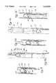
- FIG. 6is a side view of one embodiment of the valvulotome of the present invention.
- FIG. 8is a cross section view taken along lines 8--8 of FIG. 7;
- FIG. 8ais a cross section view taken along lines 8a--8a of FIG. 7;
- FIG. 9is a side view of the valvulotome similar to FIG. 6 but with the cutting section pivotal to increase pressure in a transition region;
- FIG. 10is an additional embodiment of the valvulotome of the present invention including a cutting head having a blade configuration
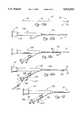
- FIG. 11aillustrates a preferred method wherein the valvulotome is inserted through an entry site and moved through an exit site for coupling with an endoscope
- FIG. 11billustrates a further step wherein the method wherein the valvulotome is drawn with the endoscope through the exit site and a vein valve;
- FIG. 11cillustrates a further step in the method wherein the valvulotome is removed through the entry site and the endoscope disengaged for removal through the exit site;
- FIGS. 13A-15illustrate steps in a preferred method for assembling the combination of an endoscope and a valvulotome of the present invention
- FIG. 13Aillustrates a side elevation view of the valvulotome including a control member
- FIG. 13Billustrates a side elevation view of an endoscope having a working channel
- FIG. 14Aillustrates an assembly step whereby the control member of the valvulotome is back-loaded into the working channel of the endoscope; and a pin vice is attached to the valvulotome;
- FIG. 14Billustrates a further assembly step where a pin vice is attached to the valvulotome
- FIG. 15illustrates a side view of the valvulotome-endoscope combination with a torque handle permanently fixed to the control member of the valvulotome.
- a valvulotomeis illustrated in FIG. 1 and designated generally by the reference numeral 10.
- the valvulotome 10includes a cutting head 12 and a control member 14.
- the valvulotome 10is illustrated to be operatively disposed in the saphenous vein 16 of a leg 18.
- the vein 16has a central axis 17 and a vessel wall 19 which are best illustrated in the enlarged view of FIG. 6.
- the leg 18is illustrated in FIG. 1, it will be apparent that the valvulotome 10 can be equally effective in preparing other veins such as those occurring in the arms (not shown) to improve circulation for example to the hand.
- the leg 18extends downward from a groin 21 and includes an upper leg or thigh 23, a knee 24, and a lower leg 25 which is connected to a foot 27.
- the skeletal structure in this regionincludes a pelvis 30, a femur 32, in the thigh 23, and a tibia 34 and fibula 36 in the lower leg 25.
- the circulatory systemalso includes the venous system which carries blood with carbon dioxide and various waste products from the cells at the extremities back to the organs, such as the heart (not shown).
- the kidneysremove the waste products from the blood
- the lungsoxygenate the blood
- the heartpumps the nutrified blood back into the femoral artery 41.
- the flowis reversed. This flow is in the direction of an arrow 54 from an upstream end 56 to a downstream end 58.
- vein 16When a person is standing, blood flow in the femoral artery 41 is enhanced by gravitation. However, blood flow in the vein 16 is resisted by gravity. For this reason, the vein 16 commonly includes several valves 61 which facilitate flow toward the downstream end 58 but which inhibit flow toward the upstream end 56. With these valves 61, the flow of blood in the saphenous vein 16 is encouraged against the gravitational force.
- the problem being solved by the present inventionoccurs when the flow of blood to the extremities, such as the hand or foot 27, is insufficient to nourish the cell in those distal regions.
- This reduced blood flowmay result from blockage such as an embolus 63, or arterial sclerosis, a thickening of the vessel walls.
- the saphenous vein 16has been used for this purpose. Turning this vein into an arterial graft removes it from the venous system but other veins can pick up the additional demand for return blood flow.
- This procedure for reversing the vein 16works best in the thigh 23 where the artery 41 and vein 16 maintain a fairly constant diameter. But the procedure is much less effective for bypassing greater lengths of the artery 41 due to the reduced diameters of both the artery 41 and vein 16 in the regions of the lower leg 25. In FIG. 2, these diameters are exaggerated where the narrow upstream end of the vein 16 is connected to the enlarged upstream end of the artery 41 at the site 65. This mismatch also occurs at the distal site 67 where the vein 16 is enlarged but the artery 41 is reduced in diameter. Nevertheless, this procedure for reversing the vein 16 orients the valves 61 in a manner that flow toward the extremity, such as the foot 27, is facilitated rather than inhibited. Reversing the vein 16, also reverses the valve 61 so the flow is now accommodated in the downward direction as shown by the arrow 70.
- the proximal site 65may be in the region of the groin 21, while the distal site 67 might be in the lower leg 25 where the vein 16 is connected to the artery 45.
- FIGS. 4 and 5Two of these prior art instruments are illustrated in FIGS. 4 and 5.
- FIG. 4The device of FIG. 4 was previously mentioned with reference to its U.S. Pat. No. 5,171,316.
- This deviceis not particularly elongate and has been provided with a blunt lateral nose 70. While this blunt nose 70 has generally protected the walls of the vein 16 from being cut, it has tended to extend into tributary veins, such as the vein 72, exposing the vein junction to a sharpened edge 74. Under these circumstances, this valvulotome of the prior art has greatly damaged the wall of the vein 16.
- the prior art valvulotome illustrated in FIG. 5is pulled through the vein 16 in the upstream direction by a pulling catheter 76 which is attached to cutting prongs 78. Two of these prongs 78 are provided in an attempt to cut or disrupt multiple valve leaflets at the same time.
- the prongs 78have been maintained in a fixed space relationship so that the cutting characteristics of the larger valves 61 have differed considerably from those associated with the smaller valves 61. It follows that the disruption of the valves has been unrepeatable and unpredictable.
- An endoscope 81has been used with this valvulotome to facilitate viewing of the cutting operation
- the valvulotome 10 of the present inventiongreatly improves the ability to cut the leaflets of the vein 61 while reducing any possibility for damage to the primary vein 16 or tributary veins 72.
- the cutting head 12can be inserted through a lower incision 87 into the vein 16 and through the valve 61. Pulling a proximal end 90 of the control member 14 (which has been left extending through the incision 87) draws the cutting head 12 at a distal end 92 of the control member 14 proximally back through the vein 16. In this procedure, the cutting head 12 disrupts each of the valves 61 thereby facilitating blood flow in the reverse direction.
- An upper incision 94may also be provided in another procedure described in greater detail below.
- the vein 16is illustrated to have the central axis 17.
- tributary veinssuch as the vein 72
- the length of the cutting head 12may be several times the width of the cutting head 12 which is preferably greater than the radius of the vein 16.
- the cutting head 12has an elongate section 101, a return section 103, and a lateral section 105 disposed therebetween at the distal end 90 of the valvulotome 10 and cutting head 12.
- the cutting head 12also includes a cutting section 107 which extends between the return section 103 and the elongate section 101.
- a transition section 109connects the cutting section 107 to the return section 103 (at an angle ⁇ ), and includes the proximal-most point 112 of the cutting head 12.
- the cutting section 107is sharpened to form a cutting edge 114 along a major portion of the width of the cutting head 12 defined by the separation of the width of the cutting head 12. In the illustrated embodiment, this width is defined by the distance separating the elongate section 101 and the return section 103.
- a preferred embodiment of the valvulotome 10can be formed from a single wire having a circular cross section.
- the wirewill typically be formed of stainless steel and may have a diameter such as 0.14 inches.
- the elongate section 101can be formed as an extension of the control member 14.
- the wirecan the be bent back on itself through the lateral region 105 preferably along an arc which may be a circle having a radius R such as 0.035 inches.
- the diameter of the circle forming the lateral region 105generally defines the width of the cutting head 12.
- the return section 103extends backwardly along and generally parallel to the elongate section 101.
- the cutting section 107is straight although this is not required by the invention. In other embodiments, the cutting section 107 may bend increasingly toward the elongate section 101 or bend increasingly away from the elongate section 101. The end of the wire forming the cutting section 107 can be left free of the elongate section 101 or attached to the elongate section 101 for example by a weld 115.
- the cutting edge 114is best illustrated in the cross-sectional view of FIG. 8. From this view it can be seen that the circular wire forming the cutting head 12 can be ground to form lateral surfaces 116, 118 which extend to the cutting edge 114.
- this cutting edge 114 in the cutting section 107 and transition section 109is of particular interest to the present invention. It is generally desirable that the outermost surface of the cutting head 12 have no sharpened edges or projections. Thus the rounded surface of the wire forming the elongate section 101, the lateral section 105, and the return section 103 is preferred. It is also desirable that these rounded characteristics extend along at least a portion of the transition section 109. In the illustrated embodiment, these rounded characteristics are insured by stopping the cutting edge 114 short of the proximal-most point 112. This is perhaps best illustrated in FIG. 8a where the proximal-most point 112 is shown to be within a wedge 121 formed between the lateral surfaces 116 and 118.
- Disruption of the valve 81is enhanced when the angle ⁇ is such that the cutting section 107 can enter the cusp 83 and initially exert a pressure on the cusp 83 which is greater in proximity to the return section 103 than in proximity to the elongate section 101. If the angle ⁇ were 90°, as in the prior art, this characteristic would not occur. Due to the natural formation of the cusp 83, an angle ⁇ of 90° unfortunately produces the greatest pressure in proximity to the elongate section 101. As a consequence, cutting with this prior art configuration starts at the inner edge of the cusp 83 and progresses outwardly.
- the cutting head 12By providing the cutting head 12 with an angle ⁇ which is less than 90°, pressure is increased in the transition region 109 so that cutting tends to occur along the cusp 83, from the outside of the cusp 83 inwardly. This tends to increase the length of the cusp thereby providing for a greater disruption of the valve 61.
- the angle ⁇is fixed in a range between 55° and 61°. In this range, cutting of the valve cusp 83 begins in proximity to the wall of the vein 16, and progresses inwardly to the central edge of the cusp 83.
- the cutting section 107is not welded to the elongate section 101 so that the cutting edge 114 is free to pivot along an arrow 125 toward the return section 103 progressively decreasing the angle ⁇ . With this freedom of movement, the angle ⁇ is progressively decreased thereby progressively increasing the pressure at the transition region 109 until cutting occurs at the proximal-most point 112.
- FIG. 10The invention can also be embodied as illustrated in FIG. 10 wherein similar structural elements are designated by the same reference numeral, followed by the lower case "a".
- the embodiment of FIG. 10includes a control member 14a and cutting head 12a.
- the cutting head 12ais formed in a blade configuration but has lateral surfaces 101a, 103a, 105a, 107a and 109a which are similar to the sections 101-109 previously described.
- the surfaces 101a, 103a and 105aare preferably free of sharp edges and projections.
- the surfaces 101a and 103ahave a generally parallel disposition which tends to maintain the alignment of these surfaces as well as the cutting head 12a generally parallel to the axis 17 of the vein 16.
- the cutting surface 107ais disposed at the angle ⁇ to the surface 103a but preferably extends outwardly from the surface 101a a distance which is short of the surface 103a. This insures that cutting does not occur too close to the wall of the vein 16.
- the blade forming the cutting head 12acan be welded or otherwise attached to the control member 14a.
- a hole 130can be provided near the distal end of the cutting head 12a to facilitate visualization as discussed in greater detail below. In the embodiment of FIG. 7, this hole 130 occurs naturally with the spacing of the wire which forms the elongate section 101 and return section 103.
- valvulotomeshave been inserted through the lower incision 87 and forced upwardly through the valves 61. Withdrawing the valvulotome 10 has tended to disrupt the valves 61 sufficiently to promote reversed flow. Early attempts at valve disruption were conducted blindly. More recently, endoscopes have been used to view the cutting of each valve. One such system has been discussed with reference to the prior art of FIG. 5.
- the valvulotome 10 of the present inventionis particularly adapted for use in a procedure which greatly improves visualization of the valve cutting.
- the cutting head 12is introduced through the lower incision 87 upwardly through the valves 61 in a manner previously discussed.
- the upper incision 94is formed above the last valve to be cut, and the cutting head 12 is passed outwardly through this incision as illustrated in FIG. 11a.
- an endoscope 132can be attached, for example by a suture 134, through the hole 130.
- the endoscope 132will commonly include fiberoptics which at the distal end of the endoscope focus light along a focal length 136 to a focal point 138.
- the length of the suture 134 in a preferred methodis chosen so that the focal point 138 is disposed along the cutting edge 114 of the cutting head 112. Maintaining this distance ensures that images along the cutting edge 114 are maintained in relatively sharp focus.
- the assembled combinationcan be drawn back through the upper incision 94 downwardly into the vein 16.
- the sharp focus of the endoscope 132 along the cutting edge 114gives a clear view of the operation prior to and during valve disruption. Sequentially and perhaps repeatedly disrupting the cusps 83 and 85 of the valves 61 will ultimately bring the cutting head 12 to the lower incision 87.
- the cutting headcan be removed through the incision 87 and the suture 134 cut to permit separation of the valvulotome 10 and the endoscope 132.
- the endoscope 132can be drawn upwardly through the vein and removed through the upper incision 94.
- the proximal end of the valvulotome 10can be attached to the distal end of the endoscope 132.
- This attachmentwill typically be accomplished by inserting the control member 14 into the working channel (not shown) which is commonly provided in the endoscope 132.
- the control member 14can be attached or otherwise fixed in this position, so that the focal point 138 of the endoscope 132 lies along the cutting edge 114 to achieve the advantages previously discussed.
- the cutting edge 114faces toward the endoscope 132. This offers the unique combination of advantages which facilitates viewing of the valve disruption with only a single lower incision 87.
- Both the cutting head 12 and the endoscope 132 in this assemblycan be inserted through the lower incision 87 with at least the cutting head 12 extending through the most distal of the valves to be disrupted. Drawing this assembly downwardly enables the cusps 83, 85 to be cut. Notably, this cutting can be viewed from the opposite side of the valve 61.
- FIGS. 13-15illustrate a preferred method for assembling the combination in FIG. 12.
- the valvulotome 10is illustrated with the elongate control member 14 extending between the proximal end 90 and distal end 92.
- the cutting head 12is formed with the elongate section 101 integral with and extending distally of the control member 14 at the distal end 92.
- FIG. 13Billustrates the side view of the endoscope 132 with an eyepiece 141 at a proximal end 143 and a working channel 145 extending to a distal end 147.
- the proximal end 90 of the valvulotome 10is back-loaded into the working channel 145 of the endoscope 132 at the distal end 147.
- This stepis illustrated in FIG. 14A.
- the proximal end 90has been fully inserted into the working channel 145 and extends through a Y-fitting 149 attached to the endoscope 132 at the proximal end of the working channel 145.
- this Y-fitting 149includes a compression seal 152 which is axially compressible to radially engage the control member 14.
- a pin vice 154can be attached to the proximal end 90 where the vice 154 functions as a handle facilitating the axial and rotational movement of the control member 14 and cutting head 12.
- the cutting head 12can be moved axially and rotationally within the working channel 145 by operation of the handle or vice 154.
- this fixed axial relationshipcan be maintained by tightening the compression seal 152.
- the axial seal 152of course functions as a seal so that various drugs can be injected through a side channel 153 into the working channel 145 to exit the endoscope 132 at its distal end 147 in proximity to the cutting head 12.
- FIG. 15A further embodiment of the invention is illustrated in FIG. 15. This embodiment is similar to that discussed with reference to FIGS. 13 and 14 but the final assembly of the combination is accomplished by the manufacturer rather than the surgeon.
- the manufacturing processincludes the back-loading of the valvulotome 10 into the endoscope 132 by the manufacturer.
- a torque knob 156can be permanently molded onto the proximal end 90 of the endoscope 10. This completed assembly can then be sterilized and sold as a completed combination, no further assembly being required by the surgeon.
- the valvulotome 10is formed from stainless steel wire having a diameter of 0.014 inches.
- the radius of curvature R of the lateral region 105is 0.035 inches while the radius of curvature r in the transition region 109 is 0.010 inches.
- the elongate section 101 and return section 103are generally parallel and are diametrically tangential to the curve forming the lateral section 105.
- the length of the cutting head 12is approximately 0.183 inches from the distal-most end of the lateral section 105 to the proximal-most point 112 in the transition 109.
- the width of the cutting head 12 in this embodimentis equal to the diameter of the curve forming the lateral section 105. It follows that the length-to-width ratio of this embodiment is 2.0 which is preferred for the axial orientation desired for the cutting head 12 within the vein 16. Length-to-width ratios in a range 2 and 4 are generally preferred.
- the length of the section 107is generally determined by the angle ⁇ . In an embodiment including the weld 115, the angle ⁇ is preferably less than 90° but greater than 30°. In a preferred embodiment, the angle ⁇ is 55° and the length of the cutting section 107 is about 0.06 inches.
- the valvulotome 10could be formed from different materials although the material in the cutting section 107 must be capable of holding a sharp edge.
- the radii R and rcan vary considerably although it is generally desirable that some curvature occur at the respective locations.
- the sections 101 and 103may have other than a parallel orientation although this configuration seems to be preferred in most cases.
- the angle ⁇ between the cutting region 107 and the return region 103can also vary considerably and may even be variable in a particular embodiment such as that discussed with reference to FIG. 9.
Landscapes
- Health & Medical Sciences (AREA)
- Surgery (AREA)
- Life Sciences & Earth Sciences (AREA)
- Biomedical Technology (AREA)
- Nuclear Medicine, Radiotherapy & Molecular Imaging (AREA)
- Engineering & Computer Science (AREA)
- Vascular Medicine (AREA)
- Heart & Thoracic Surgery (AREA)
- Medical Informatics (AREA)
- Molecular Biology (AREA)
- Animal Behavior & Ethology (AREA)
- General Health & Medical Sciences (AREA)
- Public Health (AREA)
- Veterinary Medicine (AREA)
- Surgical Instruments (AREA)
Abstract
Description
Claims (27)
Priority Applications (6)
| Application Number | Priority Date | Filing Date | Title |
|---|---|---|---|
| US08/185,555US5522824A (en) | 1994-01-24 | 1994-01-24 | Valvulotome and method for making and using same |
| JP7519564AJPH09510886A (en) | 1994-01-24 | 1994-12-29 | Valve opener and method of manufacturing and using the same |
| PCT/US1994/014894WO1995019737A1 (en) | 1994-01-24 | 1994-12-29 | Valvulotome and method for making and using same |
| DE69432669TDE69432669T2 (en) | 1994-01-24 | 1994-12-29 | valvulotomes |
| EP95907254AEP0741544B1 (en) | 1994-01-24 | 1994-12-29 | Valvulotome |
| CA002180868ACA2180868A1 (en) | 1994-01-24 | 1994-12-29 | Valvulotome and method for making and using same |
Applications Claiming Priority (1)
| Application Number | Priority Date | Filing Date | Title |
|---|---|---|---|
| US08/185,555US5522824A (en) | 1994-01-24 | 1994-01-24 | Valvulotome and method for making and using same |
Publications (1)
| Publication Number | Publication Date |
|---|---|
| US5522824Atrue US5522824A (en) | 1996-06-04 |
Family
ID=22681483
Family Applications (1)
| Application Number | Title | Priority Date | Filing Date |
|---|---|---|---|
| US08/185,555Expired - LifetimeUS5522824A (en) | 1994-01-24 | 1994-01-24 | Valvulotome and method for making and using same |
Country Status (6)
| Country | Link |
|---|---|
| US (1) | US5522824A (en) |
| EP (1) | EP0741544B1 (en) |
| JP (1) | JPH09510886A (en) |
| CA (1) | CA2180868A1 (en) |
| DE (1) | DE69432669T2 (en) |
| WO (1) | WO1995019737A1 (en) |
Cited By (50)
| Publication number | Priority date | Publication date | Assignee | Title |
|---|---|---|---|---|
| US5868768A (en)* | 1995-06-07 | 1999-02-09 | Baxter International Inc. | Method and device for endoluminal disruption of venous valves |
| US5876413A (en)* | 1995-05-19 | 1999-03-02 | General Surgical Innovations, Inc. | Methods and devices for blood vessel harvesting |
| US6090118A (en) | 1998-07-23 | 2000-07-18 | Mcguckin, Jr.; James F. | Rotational thrombectomy apparatus and method with standing wave |
| US6152139A (en)* | 1997-01-24 | 2000-11-28 | Heartenmedical, Inc. | Device and method for preparing veins |
| US6280455B1 (en)* | 1996-03-20 | 2001-08-28 | Cardiothoracic Systems, Inc. | Surgical instrument for facilitating the detachment of an artery and the like |
| US20030020662A1 (en)* | 2001-04-27 | 2003-01-30 | Brian St. Hillaire | Diversity slot antenna |
| US20030028206A1 (en)* | 1999-02-02 | 2003-02-06 | Samuel Shiber | Vessel cleaner and barrier |
| US6758851B2 (en) | 1999-02-02 | 2004-07-06 | Samuel Shiber | Vessel cleaner |
| US20050192606A1 (en)* | 2004-02-27 | 2005-09-01 | Paul Ram H.Jr. | Valvulotome with a cutting edge |
| US7037316B2 (en) | 1997-07-24 | 2006-05-02 | Mcguckin Jr James F | Rotational thrombectomy device |
| US7300399B2 (en) | 1998-12-01 | 2007-11-27 | Atropos Limited | Surgical device for retracting and/or sealing an incision |
| US20080215072A1 (en)* | 2007-02-15 | 2008-09-04 | Graham Kelly | Methods and apparatus for utilization of barbed sutures in human tissue including a method for eliminating or improving blood flow in veins |
| US7540839B2 (en) | 1999-10-14 | 2009-06-02 | Atropos Limited | Wound retractor |
| US7559893B2 (en) | 1998-12-01 | 2009-07-14 | Atropos Limited | Wound retractor device |
| US7645261B2 (en) | 1999-10-22 | 2010-01-12 | Rex Medical, L.P | Double balloon thrombectomy catheter |
| US20100286719A1 (en)* | 2004-02-27 | 2010-11-11 | Paul Ram H | Valvulotome device and method |
| US7867164B2 (en) | 1999-10-14 | 2011-01-11 | Atropos Limited | Wound retractor system |
| US8016755B2 (en) | 2000-10-19 | 2011-09-13 | Applied Medical Resources Corporation | Surgical access apparatus and method |
| US8021296B2 (en) | 1999-12-01 | 2011-09-20 | Atropos Limited | Wound retractor |
| US8109873B2 (en) | 2007-05-11 | 2012-02-07 | Applied Medical Resources Corporation | Surgical retractor with gel pad |
| US8157835B2 (en) | 2001-08-14 | 2012-04-17 | Applied Medical Resouces Corporation | Access sealing apparatus and method |
| US8187178B2 (en) | 2007-06-05 | 2012-05-29 | Atropos Limited | Instrument access device |
| US8187177B2 (en) | 2003-09-17 | 2012-05-29 | Applied Medical Resources Corporation | Surgical instrument access device |
| US8226552B2 (en) | 2007-05-11 | 2012-07-24 | Applied Medical Resources Corporation | Surgical retractor |
| US8235054B2 (en) | 2002-06-05 | 2012-08-07 | Applied Medical Resources Corporation | Wound retractor |
| US8262568B2 (en) | 2008-10-13 | 2012-09-11 | Applied Medical Resources Corporation | Single port access system |
| US8267858B2 (en) | 2005-10-14 | 2012-09-18 | Applied Medical Resources Corporation | Wound retractor with gel cap |
| US8343047B2 (en) | 2008-01-22 | 2013-01-01 | Applied Medical Resources Corporation | Surgical instrument access device |
| US8375955B2 (en) | 2009-02-06 | 2013-02-19 | Atropos Limited | Surgical procedure |
| US8388526B2 (en) | 2001-10-20 | 2013-03-05 | Applied Medical Resources Corporation | Wound retraction apparatus and method |
| US8414543B2 (en) | 1999-10-22 | 2013-04-09 | Rex Medical, L.P. | Rotational thrombectomy wire with blocking device |
| US8657740B2 (en) | 2007-06-05 | 2014-02-25 | Atropos Limited | Instrument access device |
| US8703034B2 (en) | 2001-08-14 | 2014-04-22 | Applied Medical Resources Corporation | Method of making a tack-free gel |
| US8734336B2 (en) | 1998-12-01 | 2014-05-27 | Atropos Limited | Wound retractor device |
| US8758236B2 (en) | 2011-05-10 | 2014-06-24 | Applied Medical Resources Corporation | Wound retractor |
| US8932214B2 (en) | 2003-02-25 | 2015-01-13 | Applied Medical Resources Corporation | Surgical access system |
| US8986202B2 (en) | 1999-10-14 | 2015-03-24 | Atropos Limited | Retractor |
| US9271753B2 (en) | 2002-08-08 | 2016-03-01 | Atropos Limited | Surgical device |
| US9289200B2 (en) | 2010-10-01 | 2016-03-22 | Applied Medical Resources Corporation | Natural orifice surgery system |
| US9289115B2 (en) | 2010-10-01 | 2016-03-22 | Applied Medical Resources Corporation | Natural orifice surgery system |
| US9351759B2 (en) | 2007-06-05 | 2016-05-31 | Atropos Limited | Instrument access device |
| US9642608B2 (en) | 2014-07-18 | 2017-05-09 | Applied Medical Resources Corporation | Gels having permanent tack free coatings and method of manufacture |
| US9757110B2 (en) | 1998-12-01 | 2017-09-12 | Atropos Limited | Instrument access device |
| US9782191B2 (en) | 2014-01-21 | 2017-10-10 | Cook Medical Technologies Llc | Cutting devices and methods |
| US9949730B2 (en) | 2014-11-25 | 2018-04-24 | Applied Medical Resources Corporation | Circumferential wound retraction with support and guidance structures |
| US10172641B2 (en) | 2014-08-15 | 2019-01-08 | Applied Medical Resources Corporation | Natural orifice surgery system |
| US10368908B2 (en) | 2015-09-15 | 2019-08-06 | Applied Medical Resources Corporation | Surgical robotic access system |
| US10575840B2 (en) | 2015-10-07 | 2020-03-03 | Applied Medical Resources Corporation | Wound retractor with multi-segment outer ring |
| US10674896B2 (en) | 2016-09-12 | 2020-06-09 | Applied Medical Resources Corporation | Surgical robotic access system for irregularly shaped robotic actuators and associated robotic surgical instruments |
| US11471142B2 (en) | 2013-03-15 | 2022-10-18 | Applied Medical Resources Corporation | Mechanical gel surgical access device |
Families Citing this family (5)
| Publication number | Priority date | Publication date | Assignee | Title |
|---|---|---|---|---|
| US5749882A (en)* | 1995-10-18 | 1998-05-12 | Applied Medical Resources Corporation | Apparatus for disrupting vein valves |
| US6652515B1 (en)* | 1997-07-08 | 2003-11-25 | Atrionix, Inc. | Tissue ablation device assembly and method for electrically isolating a pulmonary vein ostium from an atrial wall |
| EP0979635A2 (en) | 1998-08-12 | 2000-02-16 | Origin Medsystems, Inc. | Tissue dissector apparatus |
| US6558313B1 (en) | 2000-11-17 | 2003-05-06 | Embro Corporation | Vein harvesting system and method |
| US9770230B2 (en) | 2006-06-01 | 2017-09-26 | Maquet Cardiovascular Llc | Endoscopic vessel harvesting system components |
Citations (26)
| Publication number | Priority date | Publication date | Assignee | Title |
|---|---|---|---|---|
| US2655154A (en)* | 1952-12-05 | 1953-10-13 | Richter Bruno | Valvulotome |
| US3837345A (en)* | 1973-08-31 | 1974-09-24 | A Matar | Venous valve snipper |
| US4315511A (en)* | 1979-09-02 | 1982-02-16 | Thomas J. Fogarty | Endarterectomy apparatus |
| US4449321A (en)* | 1982-12-23 | 1984-05-22 | Meritus Industries, Inc. | Crib toy |
| US4493321A (en)* | 1982-05-25 | 1985-01-15 | Leather Robert P | Venous valve cutter for the incision of valve leaflets in situ |
| US4528982A (en)* | 1983-01-07 | 1985-07-16 | Astra Meditec Aktiebolag | Head assembly for a vein stripper |
| US4655217A (en)* | 1985-10-11 | 1987-04-07 | Reed Matt H | Method and apparatus for disabling vein valves in-situ |
| US4739760A (en)* | 1986-06-06 | 1988-04-26 | Thomas J. Fogarty | Vein valve cutter apparatus |
| US4768508A (en)* | 1986-06-06 | 1988-09-06 | Thomas J. Fogarty | Vein valve cutting method |
| DE3717926A1 (en)* | 1987-05-27 | 1988-12-08 | Leibinger Medizintech | Venous valve incision device |
| US4791913A (en)* | 1987-12-14 | 1988-12-20 | Baxter Travenol Laboratories, Inc. | Optical valvulotome |
| WO1989009029A1 (en)* | 1989-02-16 | 1989-10-05 | Taheri Syde A | Method and apparatus for removing venous valves |
| US4924882A (en)* | 1988-02-26 | 1990-05-15 | Donovan Thomas J | Electronic cuspotome and method of using the same |
| US4952215A (en)* | 1988-02-29 | 1990-08-28 | Boisurge, Inc. | Valvulotome with leaflet disruption heads and fluid supply |
| US5026383A (en)* | 1989-06-14 | 1991-06-25 | Nobles Anthony A | Apparatus for in-situ cutting of valves within veins and method therefor |
| US5047041A (en)* | 1989-08-22 | 1991-09-10 | Samuels Peter B | Surgical apparatus for the excision of vein valves in situ |
| US5049154A (en)* | 1989-08-07 | 1991-09-17 | Berkshire Research & Development, Inc. | Adjustable intra-luminal valvulotome |
| US5061240A (en)* | 1990-04-02 | 1991-10-29 | George Cherian | Balloon tip catheter for venous valve ablation |
| US5092872A (en)* | 1989-07-28 | 1992-03-03 | Jacob Segalowitz | Valvulotome catheter |
| US5133725A (en)* | 1989-08-07 | 1992-07-28 | Berkshire Research And Development, Inc. | Adjustable intra-liminal valvulotome |
| US5141491A (en)* | 1988-01-27 | 1992-08-25 | Medical Innovation Ab | Device for cutting venous valves |
| US5152771A (en)* | 1990-12-31 | 1992-10-06 | The Board Of Supervisors Of Louisiana State University | Valve cutter for arterial by-pass surgery |
| US5171316A (en)* | 1991-02-19 | 1992-12-15 | Pilling Co. | Valvulotome |
| EP0527312A1 (en)* | 1991-08-14 | 1993-02-17 | Convergenza Ag | Rinsing catheter |
| US5284478A (en)* | 1992-06-08 | 1994-02-08 | Nobles Anthony A | Detachable tip optical valvulotome |
| US5370651A (en)* | 1989-02-17 | 1994-12-06 | Summers; David P. | Distal atherectomy catheter |
Family Cites Families (3)
| Publication number | Priority date | Publication date | Assignee | Title |
|---|---|---|---|---|
| US4290427A (en)* | 1979-11-26 | 1981-09-22 | Thomas J. Fogarty | Endarterectomy apparatus |
| JP2690162B2 (en)* | 1989-11-28 | 1997-12-10 | オリンパス光学工業株式会社 | Venous valve opener |
| JPH0761335B2 (en)* | 1990-11-16 | 1995-07-05 | バークシャー リサーチ アンド ディベロプメント インコーポレイテッド | Adjustable endoluminal valve dissector |
- 1994
- 1994-01-24USUS08/185,555patent/US5522824A/ennot_activeExpired - Lifetime
- 1994-12-29CACA002180868Apatent/CA2180868A1/ennot_activeAbandoned
- 1994-12-29DEDE69432669Tpatent/DE69432669T2/ennot_activeExpired - Fee Related
- 1994-12-29EPEP95907254Apatent/EP0741544B1/ennot_activeExpired - Lifetime
- 1994-12-29WOPCT/US1994/014894patent/WO1995019737A1/enactiveIP Right Grant
- 1994-12-29JPJP7519564Apatent/JPH09510886A/enactivePending
Patent Citations (27)
| Publication number | Priority date | Publication date | Assignee | Title |
|---|---|---|---|---|
| US2655154A (en)* | 1952-12-05 | 1953-10-13 | Richter Bruno | Valvulotome |
| US3837345A (en)* | 1973-08-31 | 1974-09-24 | A Matar | Venous valve snipper |
| US4315511A (en)* | 1979-09-02 | 1982-02-16 | Thomas J. Fogarty | Endarterectomy apparatus |
| US4493321A (en)* | 1982-05-25 | 1985-01-15 | Leather Robert P | Venous valve cutter for the incision of valve leaflets in situ |
| US4449321A (en)* | 1982-12-23 | 1984-05-22 | Meritus Industries, Inc. | Crib toy |
| US4528982A (en)* | 1983-01-07 | 1985-07-16 | Astra Meditec Aktiebolag | Head assembly for a vein stripper |
| US4655217A (en)* | 1985-10-11 | 1987-04-07 | Reed Matt H | Method and apparatus for disabling vein valves in-situ |
| US4739760A (en)* | 1986-06-06 | 1988-04-26 | Thomas J. Fogarty | Vein valve cutter apparatus |
| US4768508A (en)* | 1986-06-06 | 1988-09-06 | Thomas J. Fogarty | Vein valve cutting method |
| DE3717926A1 (en)* | 1987-05-27 | 1988-12-08 | Leibinger Medizintech | Venous valve incision device |
| US4791913A (en)* | 1987-12-14 | 1988-12-20 | Baxter Travenol Laboratories, Inc. | Optical valvulotome |
| US5141491A (en)* | 1988-01-27 | 1992-08-25 | Medical Innovation Ab | Device for cutting venous valves |
| US4924882A (en)* | 1988-02-26 | 1990-05-15 | Donovan Thomas J | Electronic cuspotome and method of using the same |
| US4952215A (en)* | 1988-02-29 | 1990-08-28 | Boisurge, Inc. | Valvulotome with leaflet disruption heads and fluid supply |
| WO1989009029A1 (en)* | 1989-02-16 | 1989-10-05 | Taheri Syde A | Method and apparatus for removing venous valves |
| US5069679A (en)* | 1989-02-16 | 1991-12-03 | Taheri Syde A | Method and apparatus for removing venous valves |
| US5370651A (en)* | 1989-02-17 | 1994-12-06 | Summers; David P. | Distal atherectomy catheter |
| US5026383A (en)* | 1989-06-14 | 1991-06-25 | Nobles Anthony A | Apparatus for in-situ cutting of valves within veins and method therefor |
| US5092872A (en)* | 1989-07-28 | 1992-03-03 | Jacob Segalowitz | Valvulotome catheter |
| US5049154A (en)* | 1989-08-07 | 1991-09-17 | Berkshire Research & Development, Inc. | Adjustable intra-luminal valvulotome |
| US5133725A (en)* | 1989-08-07 | 1992-07-28 | Berkshire Research And Development, Inc. | Adjustable intra-liminal valvulotome |
| US5047041A (en)* | 1989-08-22 | 1991-09-10 | Samuels Peter B | Surgical apparatus for the excision of vein valves in situ |
| US5061240A (en)* | 1990-04-02 | 1991-10-29 | George Cherian | Balloon tip catheter for venous valve ablation |
| US5152771A (en)* | 1990-12-31 | 1992-10-06 | The Board Of Supervisors Of Louisiana State University | Valve cutter for arterial by-pass surgery |
| US5171316A (en)* | 1991-02-19 | 1992-12-15 | Pilling Co. | Valvulotome |
| EP0527312A1 (en)* | 1991-08-14 | 1993-02-17 | Convergenza Ag | Rinsing catheter |
| US5284478A (en)* | 1992-06-08 | 1994-02-08 | Nobles Anthony A | Detachable tip optical valvulotome |
Non-Patent Citations (10)
| Title |
|---|
| "Angioscopic Valvulotome", Intramed, San Diego, California, 1992, pp. 1-4. |
| "Instructions, Valvulotome (Detachable Type)" Olympus Optical, Tokyo, Japan pp. 1-3. |
| "Leather Karmody In Situ Bypass Set", American V. Mueller division of Baxter Healthcare Corp., Chicago, IL, 1988, pp. 124, 125. |
| "Leather Retrograde Valvulotome", Baxter Healthcare Corporation brochure, Chicago, Illinois, 1988, pp. 1-2. |
| Angioscopic Valvulotome , Intramed, San Diego, California, 1992, pp. 1 4.* |
| Instructions, Valvulotome (Detachable Type) Olympus Optical, Tokyo, Japan pp. 1 3.* |
| Leather Karmody In Situ Bypass Set , American V. Mueller division of Baxter Healthcare Corp., Chicago, IL, 1988, pp. 124, 125.* |
| Leather Retrograde Valvulotome , Baxter Healthcare Corporation brochure, Chicago, Illinois, 1988, pp. 1 2.* |
| Scanlan International Surgical Instrumentation Catalog, Scanlan International, Inc., St. Paul, MN, 1988, pp. 53 54.* |
| Scanlan International Surgical Instrumentation Catalog, Scanlan International, Inc., St. Paul, MN, 1988, pp. 53-54. |
Cited By (125)
| Publication number | Priority date | Publication date | Assignee | Title |
|---|---|---|---|---|
| US8133248B2 (en) | 1995-05-19 | 2012-03-13 | Tyco Healthcare Group Lp | Methods and devices for blood vessel harvesting |
| US6840946B2 (en) | 1995-05-19 | 2005-01-11 | General Surgical Innovations, Inc. | Methods and devices for blood vessel harvesting |
| US20040193195A1 (en)* | 1995-05-19 | 2004-09-30 | Fogarty Thomas J. | Methods and devices for blood vessel harvesting |
| US5876413A (en)* | 1995-05-19 | 1999-03-02 | General Surgical Innovations, Inc. | Methods and devices for blood vessel harvesting |
| US7473262B2 (en) | 1995-05-19 | 2009-01-06 | General Surgical Innovations, Inc. | Methods and devices for blood vessel harvesting |
| US7077852B2 (en) | 1995-05-19 | 2006-07-18 | General Surgical Innovations | Methods and devices for blood vessel harvesting |
| US20050154415A1 (en)* | 1995-05-19 | 2005-07-14 | Fogarty Thomas J. | Methods and devices for blood vessel harvesting |
| US6527787B1 (en) | 1995-05-19 | 2003-03-04 | General Surgical Innovations, Inc. | Methods and devices for blood vessel harvesting |
| US20100049235A1 (en)* | 1995-05-19 | 2010-02-25 | General Surgical Innovations Inc. | Methods and devices for blood vessel harvesting |
| US7588584B2 (en) | 1995-05-19 | 2009-09-15 | General Surgical Innovations, Inc. | Methods and devices for blood vessel harvesting |
| US20040204719A1 (en)* | 1995-05-19 | 2004-10-14 | Fogarty Thomas J. | Methods and devices for blood vessel harvesting |
| US5868768A (en)* | 1995-06-07 | 1999-02-09 | Baxter International Inc. | Method and device for endoluminal disruption of venous valves |
| US6280455B1 (en)* | 1996-03-20 | 2001-08-28 | Cardiothoracic Systems, Inc. | Surgical instrument for facilitating the detachment of an artery and the like |
| US6152139A (en)* | 1997-01-24 | 2000-11-28 | Heartenmedical, Inc. | Device and method for preparing veins |
| US7037316B2 (en) | 1997-07-24 | 2006-05-02 | Mcguckin Jr James F | Rotational thrombectomy device |
| US6602264B1 (en) | 1997-07-24 | 2003-08-05 | Rex Medical, L.P. | Rotational thrombectomy apparatus and method with standing wave |
| US7507246B2 (en) | 1997-07-24 | 2009-03-24 | Rex Medical, L.P. | Rotational thrombectomy device |
| US6090118A (en) | 1998-07-23 | 2000-07-18 | Mcguckin, Jr.; James F. | Rotational thrombectomy apparatus and method with standing wave |
| US10278688B2 (en) | 1998-12-01 | 2019-05-07 | Atropos Limited | Wound retractor device |
| US8317691B2 (en) | 1998-12-01 | 2012-11-27 | Atropos Limited | Wound retractor device |
| US7300399B2 (en) | 1998-12-01 | 2007-11-27 | Atropos Limited | Surgical device for retracting and/or sealing an incision |
| US9757110B2 (en) | 1998-12-01 | 2017-09-12 | Atropos Limited | Instrument access device |
| US7559893B2 (en) | 1998-12-01 | 2009-07-14 | Atropos Limited | Wound retractor device |
| US8734336B2 (en) | 1998-12-01 | 2014-05-27 | Atropos Limited | Wound retractor device |
| US9095300B2 (en) | 1998-12-01 | 2015-08-04 | Atropos Limited | Wound retractor device |
| US9700296B2 (en) | 1998-12-01 | 2017-07-11 | Atropos Limited | Wound retractor device |
| US6818002B2 (en) | 1999-02-02 | 2004-11-16 | Samuel Shiber | Vessel cleaner and barrier |
| US6758851B2 (en) | 1999-02-02 | 2004-07-06 | Samuel Shiber | Vessel cleaner |
| US20030028206A1 (en)* | 1999-02-02 | 2003-02-06 | Samuel Shiber | Vessel cleaner and barrier |
| US9277908B2 (en) | 1999-10-14 | 2016-03-08 | Atropos Limited | Retractor |
| US7867164B2 (en) | 1999-10-14 | 2011-01-11 | Atropos Limited | Wound retractor system |
| US7540839B2 (en) | 1999-10-14 | 2009-06-02 | Atropos Limited | Wound retractor |
| US8740785B2 (en) | 1999-10-14 | 2014-06-03 | Atropos Limited | Wound retractor system |
| US8986202B2 (en) | 1999-10-14 | 2015-03-24 | Atropos Limited | Retractor |
| US9017294B2 (en) | 1999-10-22 | 2015-04-28 | Rex Medical, L.P. | Rotational thrombectomy wire with blocking device |
| US7909801B2 (en) | 1999-10-22 | 2011-03-22 | Rex Medical, L.P. | Double balloon thrombectomy catheter |
| US8414543B2 (en) | 1999-10-22 | 2013-04-09 | Rex Medical, L.P. | Rotational thrombectomy wire with blocking device |
| US7645261B2 (en) | 1999-10-22 | 2010-01-12 | Rex Medical, L.P | Double balloon thrombectomy catheter |
| US8435218B2 (en) | 1999-10-22 | 2013-05-07 | Rex Medical, L.P. | Double balloon thrombectomy catheter |
| US8657741B2 (en) | 1999-12-01 | 2014-02-25 | Atropos Limited | Wound retractor |
| US8021296B2 (en) | 1999-12-01 | 2011-09-20 | Atropos Limited | Wound retractor |
| US8070676B2 (en) | 2000-10-19 | 2011-12-06 | Applied Medical Resources Corporation | Surgical access apparatus and method |
| US8016755B2 (en) | 2000-10-19 | 2011-09-13 | Applied Medical Resources Corporation | Surgical access apparatus and method |
| US8672839B2 (en) | 2000-10-19 | 2014-03-18 | Applied Medical Resource Corporation | Surgical access apparatus and method |
| US8911366B2 (en) | 2000-10-19 | 2014-12-16 | Applied Medical Resources Corporation | Surgical access apparatus and method |
| US8496581B2 (en) | 2000-10-19 | 2013-07-30 | Applied Medical Resources Corporation | Surgical access apparatus and method |
| US8105234B2 (en) | 2000-10-19 | 2012-01-31 | Applied Medical Resources Corporation | Surgical access apparatus and method |
| US20030020662A1 (en)* | 2001-04-27 | 2003-01-30 | Brian St. Hillaire | Diversity slot antenna |
| US8703034B2 (en) | 2001-08-14 | 2014-04-22 | Applied Medical Resources Corporation | Method of making a tack-free gel |
| US9878140B2 (en) | 2001-08-14 | 2018-01-30 | Applied Medical Resources Corporation | Access sealing apparatus and method |
| US8870904B2 (en) | 2001-08-14 | 2014-10-28 | Applied Medical Resources Corporation | Access sealing apparatus and method |
| US9669153B2 (en) | 2001-08-14 | 2017-06-06 | Applied Medical Resources Corporation | Method of manufacturing a tack-free gel for a surgical device |
| US8157835B2 (en) | 2001-08-14 | 2012-04-17 | Applied Medical Resouces Corporation | Access sealing apparatus and method |
| US8388526B2 (en) | 2001-10-20 | 2013-03-05 | Applied Medical Resources Corporation | Wound retraction apparatus and method |
| US10507017B2 (en) | 2002-06-05 | 2019-12-17 | Applied Medical Resources Corporation | Wound retractor |
| US8973583B2 (en) | 2002-06-05 | 2015-03-10 | Applied Medical Resources Corporation | Wound retractor |
| US8235054B2 (en) | 2002-06-05 | 2012-08-07 | Applied Medical Resources Corporation | Wound retractor |
| US9561024B2 (en) | 2002-06-05 | 2017-02-07 | Applied Medical Resources Corporation | Wound retractor |
| US9737335B2 (en) | 2002-08-08 | 2017-08-22 | Atropos Limited | Device |
| US10405883B2 (en) | 2002-08-08 | 2019-09-10 | Atropos Limited | Surgical device |
| US9271753B2 (en) | 2002-08-08 | 2016-03-01 | Atropos Limited | Surgical device |
| US9307976B2 (en) | 2002-10-04 | 2016-04-12 | Atropos Limited | Wound retractor |
| US9295459B2 (en) | 2003-02-25 | 2016-03-29 | Applied Medical Resources Corporation | Surgical access system |
| US8932214B2 (en) | 2003-02-25 | 2015-01-13 | Applied Medical Resources Corporation | Surgical access system |
| US8357086B2 (en) | 2003-09-17 | 2013-01-22 | Applied Medical Resources Corporation | Surgical instrument access device |
| US8187177B2 (en) | 2003-09-17 | 2012-05-29 | Applied Medical Resources Corporation | Surgical instrument access device |
| US20050192606A1 (en)* | 2004-02-27 | 2005-09-01 | Paul Ram H.Jr. | Valvulotome with a cutting edge |
| US20100286719A1 (en)* | 2004-02-27 | 2010-11-11 | Paul Ram H | Valvulotome device and method |
| US8398663B2 (en) | 2004-02-27 | 2013-03-19 | Cook Medical Technologies Llc | Valvulotome device and method |
| US7717930B2 (en) | 2004-02-27 | 2010-05-18 | Cook Incorporated | Valvulotome with a cutting edge |
| US8647265B2 (en) | 2005-10-14 | 2014-02-11 | Applied Medical Resources Corporation | Hand access laparoscopic device |
| US9017254B2 (en) | 2005-10-14 | 2015-04-28 | Applied Medical Resources Corporation | Hand access laparoscopic device |
| US9101354B2 (en) | 2005-10-14 | 2015-08-11 | Applied Medical Resources Corporation | Wound retractor with gel cap |
| US9649102B2 (en) | 2005-10-14 | 2017-05-16 | Applied Medical Resources Corporation | Wound retractor with split hoops |
| US8267858B2 (en) | 2005-10-14 | 2012-09-18 | Applied Medical Resources Corporation | Wound retractor with gel cap |
| US8308639B2 (en) | 2005-10-14 | 2012-11-13 | Applied Medical Resources Corporation | Split hoop wound retractor with gel pad |
| US8313431B2 (en) | 2005-10-14 | 2012-11-20 | Applied Medical Resources Corporation | Split hoop wound retractor |
| US9474519B2 (en) | 2005-10-14 | 2016-10-25 | Applied Medical Resources Corporation | Hand access laparoscopic device |
| US8414487B2 (en) | 2005-10-14 | 2013-04-09 | Applied Medical Resources Corporation | Circular surgical retractor |
| US20080215072A1 (en)* | 2007-02-15 | 2008-09-04 | Graham Kelly | Methods and apparatus for utilization of barbed sutures in human tissue including a method for eliminating or improving blood flow in veins |
| US8961410B2 (en) | 2007-05-11 | 2015-02-24 | Applied Medical Resources Corporation | Surgical retractor with gel pad |
| US8226552B2 (en) | 2007-05-11 | 2012-07-24 | Applied Medical Resources Corporation | Surgical retractor |
| US8109873B2 (en) | 2007-05-11 | 2012-02-07 | Applied Medical Resources Corporation | Surgical retractor with gel pad |
| US9351759B2 (en) | 2007-06-05 | 2016-05-31 | Atropos Limited | Instrument access device |
| US10537360B2 (en) | 2007-06-05 | 2020-01-21 | Atropos Limited | Instrument access device |
| US9408597B2 (en) | 2007-06-05 | 2016-08-09 | Atropos Limited | Instrument access device |
| US10321934B2 (en) | 2007-06-05 | 2019-06-18 | Atropos Limited | Instrument access device |
| US8657740B2 (en) | 2007-06-05 | 2014-02-25 | Atropos Limited | Instrument access device |
| US8187178B2 (en) | 2007-06-05 | 2012-05-29 | Atropos Limited | Instrument access device |
| US8343047B2 (en) | 2008-01-22 | 2013-01-01 | Applied Medical Resources Corporation | Surgical instrument access device |
| US8262568B2 (en) | 2008-10-13 | 2012-09-11 | Applied Medical Resources Corporation | Single port access system |
| US8480575B2 (en) | 2008-10-13 | 2013-07-09 | Applied Medical Resources Corporation | Single port access system |
| US8894571B2 (en) | 2008-10-13 | 2014-11-25 | Applied Medical Resources Corporation | Single port access system |
| US8721537B2 (en) | 2008-10-13 | 2014-05-13 | Applied Medical Resources Corporation | Single port access system |
| US8375955B2 (en) | 2009-02-06 | 2013-02-19 | Atropos Limited | Surgical procedure |
| US9924957B2 (en) | 2010-08-23 | 2018-03-27 | Argon Medical Devices, Inc. | Rotational thrombectomy wire with blocking device |
| US11123102B2 (en) | 2010-10-01 | 2021-09-21 | Applied Medical Resources Corporation | Natural orifice surgery system |
| US10376282B2 (en) | 2010-10-01 | 2019-08-13 | Applied Medical Resources Corporation | Natural orifice surgery system |
| US9872702B2 (en) | 2010-10-01 | 2018-01-23 | Applied Medical Resources Corporation | Natural orifice surgery system |
| US12089872B2 (en) | 2010-10-01 | 2024-09-17 | Applied Medical Resources Corporation | Natural orifice surgery system |
| US9289115B2 (en) | 2010-10-01 | 2016-03-22 | Applied Medical Resources Corporation | Natural orifice surgery system |
| US9289200B2 (en) | 2010-10-01 | 2016-03-22 | Applied Medical Resources Corporation | Natural orifice surgery system |
| US10271875B2 (en) | 2010-10-01 | 2019-04-30 | Applied Medical Resources Corporation | Natural orifice surgery system |
| US9241697B2 (en) | 2011-05-10 | 2016-01-26 | Applied Medical Resources Corporation | Wound retractor |
| US8758236B2 (en) | 2011-05-10 | 2014-06-24 | Applied Medical Resources Corporation | Wound retractor |
| US9192366B2 (en) | 2011-05-10 | 2015-11-24 | Applied Medical Resources Corporation | Wound retractor |
| US9307975B2 (en) | 2011-05-10 | 2016-04-12 | Applied Medical Resources Corporation | Wound retractor |
| US11471142B2 (en) | 2013-03-15 | 2022-10-18 | Applied Medical Resources Corporation | Mechanical gel surgical access device |
| US9782191B2 (en) | 2014-01-21 | 2017-10-10 | Cook Medical Technologies Llc | Cutting devices and methods |
| US10918408B2 (en) | 2014-01-21 | 2021-02-16 | Cook Medical Technologies Llc | Cutting devices and methods |
| US9642608B2 (en) | 2014-07-18 | 2017-05-09 | Applied Medical Resources Corporation | Gels having permanent tack free coatings and method of manufacture |
| US10952768B2 (en) | 2014-08-15 | 2021-03-23 | Applied Medical Resources Corporation | Natural orifice surgery system |
| US12262914B2 (en) | 2014-08-15 | 2025-04-01 | Applied Medical Resources Corporation | Natural orifice surgery system |
| US10172641B2 (en) | 2014-08-15 | 2019-01-08 | Applied Medical Resources Corporation | Natural orifice surgery system |
| US11583316B2 (en) | 2014-08-15 | 2023-02-21 | Applied Medical Resources Corporation | Natural orifice surgery system |
| US9949730B2 (en) | 2014-11-25 | 2018-04-24 | Applied Medical Resources Corporation | Circumferential wound retraction with support and guidance structures |
| US11382658B2 (en) | 2015-09-15 | 2022-07-12 | Applied Medical Resources Corporation | Surgical robotic access system |
| US11883068B2 (en) | 2015-09-15 | 2024-01-30 | Applied Medical Resources Corporation | Surgical robotic access system |
| US10368908B2 (en) | 2015-09-15 | 2019-08-06 | Applied Medical Resources Corporation | Surgical robotic access system |
| US11602338B2 (en) | 2015-10-07 | 2023-03-14 | Applied Medical Resources Corporation | Wound retractor with multi-segment outer ring |
| US12185932B2 (en) | 2015-10-07 | 2025-01-07 | Applied Medical Resources Corporation | Wound retractor with multi-segment outer ring |
| US10575840B2 (en) | 2015-10-07 | 2020-03-03 | Applied Medical Resources Corporation | Wound retractor with multi-segment outer ring |
| US11627867B2 (en) | 2016-09-12 | 2023-04-18 | Applied Medical Resources Corporation | Surgical robotic access system for irregularly shaped robotic actuators and associated robotic surgical instruments |
| US11992184B2 (en) | 2016-09-12 | 2024-05-28 | Applied Medical Resources Corporation | Surgical robotic access system for irregularly shaped robotic actuators and associated robotic surgical instruments |
| US10674896B2 (en) | 2016-09-12 | 2020-06-09 | Applied Medical Resources Corporation | Surgical robotic access system for irregularly shaped robotic actuators and associated robotic surgical instruments |
Also Published As
| Publication number | Publication date |
|---|---|
| JPH09510886A (en) | 1997-11-04 |
| EP0741544A1 (en) | 1996-11-13 |
| CA2180868A1 (en) | 1995-07-27 |
| WO1995019737A1 (en) | 1995-07-27 |
| EP0741544B1 (en) | 2003-05-14 |
| EP0741544A4 (en) | 1997-05-28 |
| DE69432669D1 (en) | 2003-06-18 |
| DE69432669T2 (en) | 2004-04-01 |
Similar Documents
| Publication | Publication Date | Title |
|---|---|---|
| US5522824A (en) | Valvulotome and method for making and using same | |
| US5749882A (en) | Apparatus for disrupting vein valves | |
| US5601580A (en) | Venous valve cutter | |
| EP0393834B1 (en) | Rotary catheter for atherectomy system | |
| US6887251B1 (en) | Method and apparatus for vessel harvesting | |
| US5658301A (en) | Self-centering valvulotome | |
| EP1289427B1 (en) | Apparatus for removing veins | |
| US5865844A (en) | Anti-stenotic method and product for occluded and partially occluded arteries | |
| US5047041A (en) | Surgical apparatus for the excision of vein valves in situ | |
| US8066724B2 (en) | Anastomosis apparatus and methods | |
| US7611523B2 (en) | Method for sutureless connection of vessels | |
| US5571169A (en) | Anti-stenotic method and product for occluded and partially occluded arteries | |
| US20110201991A1 (en) | Valve bypass graft device, tools, and method | |
| US20100305594A1 (en) | Percutaneous vein harvester with shielded blade | |
| EP0593600A1 (en) | Tubular surgical implant | |
| JP2690162B2 (en) | Venous valve opener | |
| US6030396A (en) | Device for removing blood vessels from the human body | |
| AU2004289277B2 (en) | Endovascular guide for use with a percutaneous device for harvesting tubular body members | |
| US20040122458A1 (en) | Percutaneous device and method for harvesting tubular body members | |
| US20090222033A1 (en) | Percutaneous device and method for harvesting tubular body members | |
| US20050021068A1 (en) | Method of stripping diseased blood vessels from the human body |
Legal Events
| Date | Code | Title | Description |
|---|---|---|---|
| AS | Assignment | Owner name:APPLIED MEDICAL RESOURCES CORP., CALIFORNIA Free format text:ASSIGNMENT OF ASSIGNORS INTEREST;ASSIGNOR:ASHBY, MARK P.;REEL/FRAME:006851/0644 Effective date:19940124 | |
| STCF | Information on status: patent grant | Free format text:PATENTED CASE | |
| FEPP | Fee payment procedure | Free format text:PAYOR NUMBER ASSIGNED (ORIGINAL EVENT CODE: ASPN); ENTITY STATUS OF PATENT OWNER: LARGE ENTITY | |
| FPAY | Fee payment | Year of fee payment:4 | |
| FPAY | Fee payment | Year of fee payment:8 | |
| FEPP | Fee payment procedure | Free format text:PAT HOLDER NO LONGER CLAIMS SMALL ENTITY STATUS, ENTITY STATUS SET TO UNDISCOUNTED (ORIGINAL EVENT CODE: STOL); ENTITY STATUS OF PATENT OWNER: LARGE ENTITY | |
| FPAY | Fee payment | Year of fee payment:12 | |
| REMI | Maintenance fee reminder mailed | ||
| AS | Assignment | Owner name:CITIBANK, N.A., TEXAS Free format text:SECURITY AGREEMENT;ASSIGNOR:APPLIED MEDICAL RESOURCES CORPORATION;REEL/FRAME:028115/0276 Effective date:20120417 | |
| AS | Assignment | Owner name:APPLIED MEDICAL RESOURCES CORPORATION, CALIFORNIA Free format text:RELEASE BY SECURED PARTY;ASSIGNOR:CITIBANK N.A., AS ADMINISTRATIVE AGENT;REEL/FRAME:066795/0595 Effective date:20240129 |