US5522790A - Retraction apparatus and methods for endoscopic surgery - Google Patents
Retraction apparatus and methods for endoscopic surgeryDownload PDFInfo
- Publication number
- US5522790A US5522790AUS08/212,122US21212294AUS5522790AUS 5522790 AUS5522790 AUS 5522790AUS 21212294 AUS21212294 AUS 21212294AUS 5522790 AUS5522790 AUS 5522790A
- Authority
- US
- United States
- Prior art keywords
- inflatable
- chamber
- maintainer
- inflatable chamber
- retraction device
- Prior art date
- Legal status (The legal status is an assumption and is not a legal conclusion. Google has not performed a legal analysis and makes no representation as to the accuracy of the status listed.)
- Expired - Lifetime
Links
Images


Classifications
- A—HUMAN NECESSITIES
- A61—MEDICAL OR VETERINARY SCIENCE; HYGIENE
- A61B—DIAGNOSIS; SURGERY; IDENTIFICATION
- A61B17/00—Surgical instruments, devices or methods
- A61B17/34—Trocars; Puncturing needles
- A61B17/3417—Details of tips or shafts, e.g. grooves, expandable, bendable; Multiple coaxial sliding cannulas, e.g. for dilating
- A—HUMAN NECESSITIES
- A61—MEDICAL OR VETERINARY SCIENCE; HYGIENE
- A61B—DIAGNOSIS; SURGERY; IDENTIFICATION
- A61B17/00—Surgical instruments, devices or methods
- A61B17/02—Surgical instruments, devices or methods for holding wounds open, e.g. retractors; Tractors
- A61B17/0218—Surgical instruments, devices or methods for holding wounds open, e.g. retractors; Tractors for minimally invasive surgery
- A—HUMAN NECESSITIES
- A61—MEDICAL OR VETERINARY SCIENCE; HYGIENE
- A61B—DIAGNOSIS; SURGERY; IDENTIFICATION
- A61B17/00—Surgical instruments, devices or methods
- A61B17/02—Surgical instruments, devices or methods for holding wounds open, e.g. retractors; Tractors
- A61B17/0281—Abdominal wall lifters
- A—HUMAN NECESSITIES
- A61—MEDICAL OR VETERINARY SCIENCE; HYGIENE
- A61B—DIAGNOSIS; SURGERY; IDENTIFICATION
- A61B17/00—Surgical instruments, devices or methods
- A61B17/22—Implements for squeezing-off ulcers or the like on inner organs of the body; Implements for scraping-out cavities of body organs, e.g. bones; for invasive removal or destruction of calculus using mechanical vibrations; for removing obstructions in blood vessels, not otherwise provided for
- A61B17/22031—Gripping instruments, e.g. forceps, for removing or smashing calculi
- A61B17/22032—Gripping instruments, e.g. forceps, for removing or smashing calculi having inflatable gripping elements
- A—HUMAN NECESSITIES
- A61—MEDICAL OR VETERINARY SCIENCE; HYGIENE
- A61B—DIAGNOSIS; SURGERY; IDENTIFICATION
- A61B90/00—Instruments, implements or accessories specially adapted for surgery or diagnosis and not covered by any of the groups A61B1/00 - A61B50/00, e.g. for luxation treatment or for protecting wound edges
- A61B90/50—Supports for surgical instruments, e.g. articulated arms
- A—HUMAN NECESSITIES
- A61—MEDICAL OR VETERINARY SCIENCE; HYGIENE
- A61B—DIAGNOSIS; SURGERY; IDENTIFICATION
- A61B17/00—Surgical instruments, devices or methods
- A61B17/34—Trocars; Puncturing needles
- A61B17/3462—Trocars; Puncturing needles with means for changing the diameter or the orientation of the entrance port of the cannula, e.g. for use with different-sized instruments, reduction ports, adapter seals
- A—HUMAN NECESSITIES
- A61—MEDICAL OR VETERINARY SCIENCE; HYGIENE
- A61B—DIAGNOSIS; SURGERY; IDENTIFICATION
- A61B17/00—Surgical instruments, devices or methods
- A61B17/00234—Surgical instruments, devices or methods for minimally invasive surgery
- A61B2017/00238—Type of minimally invasive operation
- A61B2017/00261—Discectomy
- A—HUMAN NECESSITIES
- A61—MEDICAL OR VETERINARY SCIENCE; HYGIENE
- A61B—DIAGNOSIS; SURGERY; IDENTIFICATION
- A61B17/00—Surgical instruments, devices or methods
- A61B2017/00535—Surgical instruments, devices or methods pneumatically or hydraulically operated
- A—HUMAN NECESSITIES
- A61—MEDICAL OR VETERINARY SCIENCE; HYGIENE
- A61B—DIAGNOSIS; SURGERY; IDENTIFICATION
- A61B17/00—Surgical instruments, devices or methods
- A61B2017/00535—Surgical instruments, devices or methods pneumatically or hydraulically operated
- A61B2017/00557—Surgical instruments, devices or methods pneumatically or hydraulically operated inflatable
- A—HUMAN NECESSITIES
- A61—MEDICAL OR VETERINARY SCIENCE; HYGIENE
- A61B—DIAGNOSIS; SURGERY; IDENTIFICATION
- A61B17/00—Surgical instruments, devices or methods
- A61B17/30—Surgical pincettes, i.e. surgical tweezers without pivotal connections
- A61B2017/306—Surgical pincettes, i.e. surgical tweezers without pivotal connections holding by means of suction
- A—HUMAN NECESSITIES
- A61—MEDICAL OR VETERINARY SCIENCE; HYGIENE
- A61B—DIAGNOSIS; SURGERY; IDENTIFICATION
- A61B17/00—Surgical instruments, devices or methods
- A61B17/32—Surgical cutting instruments
- A61B2017/320044—Blunt dissectors
- A61B2017/320048—Balloon dissectors
- A—HUMAN NECESSITIES
- A61—MEDICAL OR VETERINARY SCIENCE; HYGIENE
- A61B—DIAGNOSIS; SURGERY; IDENTIFICATION
- A61B17/00—Surgical instruments, devices or methods
- A61B17/34—Trocars; Puncturing needles
- A61B2017/348—Means for supporting the trocar against the body or retaining the trocar inside the body
- A61B2017/3482—Means for supporting the trocar against the body or retaining the trocar inside the body inside
- A61B2017/3484—Anchoring means, e.g. spreading-out umbrella-like structure
- A61B2017/3486—Balloon
- A—HUMAN NECESSITIES
- A61—MEDICAL OR VETERINARY SCIENCE; HYGIENE
- A61B—DIAGNOSIS; SURGERY; IDENTIFICATION
- A61B90/00—Instruments, implements or accessories specially adapted for surgery or diagnosis and not covered by any of the groups A61B1/00 - A61B50/00, e.g. for luxation treatment or for protecting wound edges
- A61B90/30—Devices for illuminating a surgical field, the devices having an interrelation with other surgical devices or with a surgical procedure
- A61B2090/306—Devices for illuminating a surgical field, the devices having an interrelation with other surgical devices or with a surgical procedure using optical fibres
Definitions
- Laparoscopydates back to the turn of the 20th Century. Early laparoscopic techniques were used primarily for diagnostic purposes to view the internal organs, without the necessity of conventional surgery. Since the 1930s, laparoscopy has been used for sterilization and, more recently, for suturing hernias. U.S. Pat. Nos. 4,919,152 and 4,944,443 are concerned with techniques for suturing hernias. Another recent innovation is the use of laparoscopic surgery for removing the gallbladder.
- U.S. patent application Ser. No. 706,781the application of which this application is a continuation-in-part, describes an apparatus and method wherein the abdominal wall is lifted away from the underlying abdominal organs by an inflatable device which is introduced laparoscopically and, once in place, inflated to engage and lift an extensive area of the abdominal wall.
- U.S. patent application Ser. No. 794,590(the "prior application"), of which this application is also a continuation-in-part, describes a number of retraction devices that are introduced into the body in a collapsed condition and, once in place, are expanded by inflating a main inflatable chamber, to retract organs or tissues and to provide access to the organ or tissue being treated.
- the retraction devices described in the applicationprovide a relatively large surface area to the organ or tissue being retracted so that retraction can take place with a minimal risk of damage to the retracted organ or tissue.
- These relatively large retraction devicesinclude auxiliary means for maintaining their shape after inflation, such as an additional second inflatable chamber having a cage-like structure, or a spring cage arrangement. These auxiliary means enable retraction to be maintained after the main inflatable chamber has been deflated by cutting apertures in it to gain access through the retraction device to treat the organ or tissue being treated.
- the retraction devices described in the prior applicationprovide a significant improvement in providing access to the organ or tissue being treated during laparoscopic surgery. Nevertheless, such devices have problems.
- an inflatable retraction device with an auxiliary cage structure providing a retraction effect equivalent to that of the main chamberis in its collapsed state, its envelope has a significant bulk.
- the bulk of a retraction device in its collapsed statewill be called the "collapsed bulk" of the retraction device.
- An inflatable retraction device that has a large collapsed bulkis difficult to package in its collapsed state so that it can be inserted into the body through a narrow trocar tube (14 mm or less in diameter).
- organwill be used to mean an organ or a tissue that is retracted by a retraction device.
- the word “treat”will be used to mean both treat and observe, and the word “treatment” will be used to mean both treatment and observation.
- the word “tissue” or the phrase “tissue to be treated”will both be used to mean the organ or the tissue that is treated through or inside a retraction device.
- An inflatable retraction devicehas a first inflatable chamber that retracts the organ when the first inflatable chamber is inflated to an expanded condition.
- the first inflatable chamberhas a first envelope.
- the inflatable retraction devicealso includes a device that inflates the first inflatable chamber into an expanded condition while in place in the body. Inside the main inflatable chamber is a non-pressurized chamber that has a second envelope attached to part of the first envelope.
- the inflatable retraction devicealso has a second inflatable chamber attached to the non-pressurized chamber that expands the non-pressurized chamber into an expanded condition when the second inflatable chamber is inflated.
- the inflatable retraction deviceincludes a device that inflates the second inflatable chamber.
- the first inflatable chamberis inflated to retract the organ, and then remains inflated, and continues to provide retraction, throughout the treatment procedure.
- the tissueis treated through an aperture in the part of the first envelope covered by the non-pressurized chamber.
- Instrumentsare passed from outside the body through a gas-tight port into the first inflatable chamber. From the first inflatable chamber, the instruments pass into the non-pressurized chamber through a port that seals around each instrument, and is self-sealing when the instrument is withdrawn. This maintains the first inflatable chamber in its inflated state.
- all or part of the envelope of the non-pressurized chambercan be made of an elastomeric material that seals around an instrument passed through it, and is self-sealing when the instrument is withdrawn.
- instrumentscan be passed from outside the body through a duct connecting to the non-pressurized chamber.
- the collapsed bulk of an inflatable retraction device according to the first aspect of the inventionis less than that of an equivalently-sized inflatable retraction device of the types described in the prior application. This is because the volume the envelopes of the non-pressurized chamber and the second inflatable chamber is less than the volume of the envelope of the additional chamber of the types of inflatable retraction device previously described.
- the inflatable retraction deviceIn a first method according to the invention of using an inflatable retraction device according to the first aspect of the invention to retract an organ inside the body to gain access to an adjacent tissue, the inflatable retraction device is placed in a collapsed state adjacent to the tissue.
- the first inflatable chamberis inflated into an expanded condition to retract the organ, and the second inflatable chamber is inflated to expand the non-pressurized chamber into an expanded condition.
- the inflatable retraction device in a collapsed conditionis secured to an endoscope adjacent to the distal end of the endoscope.
- the distal end of the endoscope, together with the inflatable retraction deviceis inserted into the body and moved towards the tissue.
- the second inflatable chamber of the inflatable retraction deviceis at least partially inflated to expand the non-pressurized chamber into an expanded condition. This also expands the first inflatable chamber into a partially-expanded condition.
- the endoscopeis manipulated while observing through the endoscope to place the at least partially expanded non-pressurized chamber adjacent to the tissue.
- the first inflatable chamberis inflated into a fully-expanded condition to retract the organ.
- the second methodenables the part of the envelope of the first inflatable chamber covered by the non-pressurized chamber to be placed accurately relative to the organ to be treated.
- An inflatable retraction devicehas a main chamber that has an envelope of an elastomeric material.
- the main chamberis inflated while in place within the body to retract the organ into a retracted condition.
- the inflatable retraction devicealso includes a maintainer that maintains the organ in its retracted condition after the main chamber is deflated.
- Using an elastomeric material for the envelope of the main inflatable chamberenables the collapsed bulk of the main chamber, and hence the collapsed bulk of the inflatable retraction device as a whole, to be reduced compared with an inflatable retraction device having the same inflated size made from a substantially inelastic material.
- the maintaineris an additional inflatable chamber that has a cage-like structure and is independent of the main inflatable chamber.
- the main inflatable chamberis removed once the additional inflatable chamber is inflated and the tissue is treated using instruments passed through the maintainer.
- the additional inflatable chamberis preferably deployed on the outside of the main inflatable chamber, but can be deployed inside the main inflatable chamber.
- the maintaineris a cage-like structure of a malleable metal or plastic deployed on the outside of the main inflatable chamber.
- the cage-like structureis expanded into an expanded condition by inflating the main inflatable chamber. Once the cage is in its expanded condition, the, main inflatable chamber can be deflated and removed, and the cage maintains the organ in its retracted condition.
- the maintainer and the main inflatable chamberare assembled together and packaged in a collapsed state.
- the maintainer and main inflatable chamber assemblyis inserted into the body and placed adjacent to the organ.
- the main inflatable chamberis inflated to retract the organ into a retracted condition.
- the maintaineris expanded to maintain the organ in its retracted condition and the main inflatable chamber is deflated.
- the collapsed bulk of the inflatable retraction devices described in the present application and in the prior applicationcan be reduced by making the additional inflatable chamber smaller. If the additional inflatable chamber is to provide a given retracting force, it can only be made smaller if its strength is increased.
- the strength of the additional inflatable chamberis increased by filling it with a solid instead of a fluid.
- the main chamber of an inflatable retraction deviceis inflated.
- the additional inflatable chamber of the inflatable retraction deviceis then filled with a slurry comprising a particulate solid in a liquid.
- the liquid component of the slurryis removed from the additional inflatable chamber, leaving the particulate solid behind.
- the particulate solidis compacted to form a rigid structure in the additional inflatable chamber.
- the particulate solidis compacted by evacuating the additional inflatable chamber.
- Alternative ways of compacting the particulate solidinclude heating and Cooling the solid.
- a self-retracting endoscopeenables endoscopic observations to be carried out inside the body without the need for a separate retraction device.
- a self-retracting endoscope for observing a tissue inside the bodyincludes an optical device for observing the tissue.
- the optical devicehas a substantially cylindrical structure, and a distal end that is inserted into the body through an incision.
- the self-retracting endoscopealso includes a retractor that is expandable to retract organs adjacent to the tissue that would otherwise obstruct the view of the tissue.
- the retractoris attached to the optical device adjacent to the distal end of the optical device and is in a collapsed state when the distal end of the optical device is inserted into the body.
- the retractoris expanded once the distal end of the optical device is inside the body, adjacent to the tissue to be observed.
- the retractoris inflatable, and is expanded by inflating it.
- the fifth aspect of the inventionenables a substantially cylindrical object, such as an inflatable retraction device in its collapsed state, to be inserted into the body without buckling or jamming.
- An insertion tube according to the fifth aspect of the inventioncomprises an elongate tubular member having a bore.
- the borereceives the object, such as the collapsed inflatable retraction device, at its proximal end.
- a stringpasses from the proximal end to the distal end of the tubular member inside the bore and returns to the proximal end of the tubular member.
- the string passing inside the boreis capable of attachment to the proximal end of the object.
- the string passing inside the boreis attached to the proximal end of the object, and the distal end of the object is inserted into the proximal end of the bore of the tubular member.
- the distal end of the tubular memberis inserted into the body.
- the string returning to the proximal end of the tubular memberis pulled to draw the object through the bore of the tubular member.
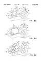
- FIG. 1shows a cross sectional view of a Type IIIA inflatable retraction device according to a first aspect of the invention in its inflated condition in the abdomen.
- FIG. 2Ais a cross sectional view showing details of the non-pressurized chamber and the second inflatable chamber of a Type IIIA inflatable retraction device according to a first aspect of the invention.
- FIG. 2Bis a cross sectional view showing a version of the non-pressurized chamber in which the part of its envelope contacting the envelope of the first inflatable chamber is removed.
- FIG. 3Ais a cross sectional view showing the non-pressurized chamber and the second inflatable chamber of a Type IIIA inflatable retraction device according to a first aspect of the invention in which the second inflatable chamber is inside the non-pressurized chamber and has its own envelope.
- FIG. 3Bis a cross sectional view showing the non-pressurized chamber and the second inflatable chamber of a Type IIIA inflatable retraction device according to a first aspect of the invention in which the second inflatable chamber is outside the non-pressurized chamber and has its own envelope.
- FIG. 4is a cross sectional view of a Type IIIA inflatable retraction device according to a first aspect of the invention in its inflated condition in the abdomen and having ducts through which instruments can be inserted into the non-pressurized chamber from outside the inflatable retraction device.
- FIG. 5is a cross sectional view of a Type IIIB inflatable retraction device according to a first aspect of the invention in its inflated condition in the abdomen.
- FIGS. 6A through 6Cshow cross sectional views of the abdomen including the bowel, the liver, and the gall bladder to illustrate a first method according to the invention of using a type IIIA or a type IIIB inflatable retraction device according to the invention to retract the bowel and lift the liver to gain access to treat the gall bladder:
- FIG. 6Ashows a packaged Type IIIA inflatable retraction device in its collapsed state inserted into the abdomen.
- FIG. 6Bshows the Type IIIA inflatable retraction device following inflation of the first inflatable chamber to retract the bowel, lift the liver, and gain access to the gall bladder.
- FIG. 6Cshows the Type IIIA inflatable retraction device following inflation of its second inflatable chamber.
- An endoscope and a cutting instrumenthas been inserted into the non-pressurized chamber to cut an aperture in the envelope of the main inflatable chamber through which to treat the gall bladder.
- FIGS. 7A through 7Eillustrate a second method according to the invention of using a type IIIA or a type IIIB inflatable retraction device according to the invention to retract an organ:
- FIG. 7Ais a cross sectional view of a partially inflated Type IIIA inflatable retraction device according to a first aspect of the invention being attached, to an endoscope prior to packaging the inflatable retraction device.
- FIGS. 7B through 7Eshow cross sectional views of the abdomen including the bowel, the liver, and the gall bladder:
- FIG. 7Bshows a packaged Type IIIA inflatable retraction device attached in a collapsed state to an endoscope prior to insertion into the abdomen.
- FIG. 7Cshows the packaged Type IIIA inflatable retraction device attached in a collapsed state to an endoscope after it has been inserted into the abdomen and the distal end of the endoscope has been placed adjacent to the gall bladder.
- FIG. 7Dshows the Type IIIA inflatable retraction device attached to an endoscope after the second inflatable chamber has been inflated, and the endoscope has been manipulated to align the treatment window in the second inflatable chamber with the gall bladder.
- FIG. 7Eshows the Type IIIA inflatable retraction device attached to an endoscope after the first inflatable chamber has been inflated to retract the bowel, lift the liver, and provide access to treat the gall bladder.
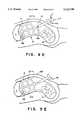
- FIG. 8Ais a schematic representation of a Type IV inflatable retraction device according to a second aspect of the invention.
- FIG. 8Bis a perspective view of a Type IVA inflatable retraction device according to a second aspect of the invention having an external inflatable maintainer.
- FIG. 8Cis a cut-away perspective view of a Type IVA inflatable retraction device according to a second aspect of the invention having an internal inflatable maintainer.
- FIG. 9Ashows a Type IVA inflatable retraction device with an inflatable maintainer according to the invention in its packaged state prior to insertion into the body.
- FIGS. 9B through 9Eshow cross sectional views of the abdomen including the bowel, the liver, and the gall bladder to illustrate the method according to the invention of using a Type IVA inflatable retraction device with an inflatable maintainer according to the invention to retract the bowel and lift the liver to gain access to treat the gall bladder:
- FIG. 9Bshows a Type IVA inflatable retraction device after the main inflatable chamber has been inflated to retract the bowel and lift the liver to provide access to treat the gall bladder.
- FIG. 9Cshows the Type IVA inflatable retraction device after the maintainer has been inflated.
- FIG. 9Dshows the Type IVA inflatable retraction device after the main inflatable chamber has been deflated.
- FIG. 9Eshows the inflatable maintainer of a Type IVA inflatable retraction device in place in the abdomen maintaining the bowel in its retracted condition and the liver in its lifted condition after the inflatable retractor has been removed from the abdomen.
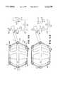
- FIGS. 10A through 10Dillustrate a Type IVB inflatable retraction device according to a second aspect of the invention having a mechanical maintainer.
- FIG. 10Ais a perspective view of the maintainer.
- FIG. 10Bis a perspective view of the inflatable retractor.
- FIG. 10Cis a perspective view of the assembled Type IVB inflatable retraction device prior to insertion into the body.
- FIG. 10Dis a perspective view of the maintainer in its expanded condition following withdrawal of the inflatable retractor.
- FIGS. 11A through 11Dshow a vertical cross sectional view of a Type IA inflatable retraction device to illustrate the high-strength inflation method according to the invention.
- FIG. 11Ashows the inflatable retraction device after its additional inflatable chamber has been filled with a slurry of a particulate solid in a liquid.
- FIG. 11Bshows the inflatable retraction device after the liquid component of the slurry has been removed its additional inflatable chamber.
- FIG. 11Cshows the inflatable retraction device after its additional inflatable chamber has been evacuated to consolidate the particulate solid.
- FIG. 11Dshows the inflatable retraction device fitted with an alternative provision for consolidating the particulate solid.
- FIGS. 12A through 12Gillustrate a self-retracting endoscope according to a fourth aspect of the invention:
- FIG. 12Ais a perspective view of a self-retracting endoscope having an inflatable retractor comprising a stack of toroidal balloons. The inflatable retractor is shown in its expanded condition.
- FIG. 12Bis a cross sectional view of an alternative configuration of the inflatable retractor.
- FIG. 12Cis a perspective view of the self-retracting endoscope with its inflatable retractor in its collapsed condition.
- FIG. 12Dis a perspective view of a variation of the self-retracting endoscope having an inflatable retractor with the inflatable retractor in its collapsed condition.
- This variationhas a substantially constant diameter circular cross section and is especially suitable for use in insufflated body cavities.
- FIG. 12Eis a cross sectional view of the abdomen showing the bowel, the liver, the gall bladder, and the self-retracting endoscope with an inflatable retractor retracting the liver to observe the gall bladder.
- FIG. 12Fis a perspective view of a self-retracting endoscope according to the invention having a mechanical retractor with the mechanical retractor in its collapsed condition.
- FIG. 12Gis a perspective view of the self-retracting endoscope having a mechanical retractor with the mechanical retractor in its expanded condition.
- FIGS. 13A through 13Dillustrate an insertion tube according to a fifth aspect of the invention:
- FIG. 13Ais a perspective view of a most basic insertion tube.
- FIG. 13Bis a perspective view of a less basic insertion tube having an eyelet.
- FIG. 13Cis a perspective view of an improved version of the insertion tube having an external narrow bore tube.
- FIG. 13Dis a perspective view of an improved version of the insertion tube having an internal narrow bore tube.
- FIG. 1shows a vertical cross sectional view of a retraction device according to the first aspect of the invention.
- This type of retraction devicehas a second inflatable chamber that expands a non-pressurized chamber into an expanded condition when the second inflatable chamber is inflated, and will be designated as a Type III retraction device.
- the Type III inflatable retraction device shown in FIG. 1 with a segmented non-pressurized chamberwill be designated as a Type IlIA inflatable retraction device.
- the inflatable retraction device 1is shown in its inflated condition.
- the inflatable retraction device 1comprises a first envelope 3 enclosing a first inflatable chamber 5. Inside the first inflatable: chamber 5 is the non-pressurized chamber 13, which is maintained in an expanded condition by the second inflatable chamber 25.
- the inflatable retraction device 1is shown being used in the abdomen A to retract the bowel B, lift the liver L, and provide access to treat the gall bladder GB.
- an aperture 4is cut in the treatment window 6 to gain access to the gall bladder GB.
- the treatment windowis the part of the first envelope 3 covered by the non-pressurized chamber 13.
- the inflatable retraction device 1may be supplied with the aperture 4 already cut in the treatment window 6.
- Instrumentssuch as the endoscope 33, pass into the first inflatable chamber 5 through the gas-tight port 9 on the first inflation tube 7, and thence through the gas-tight port 31 into the non-pressurized chamber 13 to observe or to treat the gall bladder GB. Additionally or alternatively, instruments, such as the forceps 34, can pass through the gas-tight port 32 into the first inflatable chamber, and thence through a gas-tight port, such as the port 36, into the non-pressurized chamber.
- the gas-tight ports 9, 31, 32, and 36enable the first inflatable chamber to remain inflated.
- the first envelope 3 of the inflatable retraction device 1can be made of a relatively inelastic and tough film of a plastic such as Mylar® or polyethylene.
- the preferred relatively inelastic materialis a polyethylene and nylon composite with a thickness in the range from 0.5 to 5 mils (13 to 130 microns).
- the first envelopecan be made of an elastomeric material such as latex, polyurethane, or silicone rubber with a thickness in the range from 0.5 to 5 mils (13 to 130 microns).
- the proximal end of a first inflation tube 7is sealed into the first envelope 3.
- the first inflation tube 7allows an inflation gas to pass into and out of the first inflatable chamber 5.
- the inflation gasis typically air, nitrogen or carbon dioxide, although other suitable gases may be used. Typical inflation gas pressures are in the range 0.2 to 0.4 pounds per square inch (psi) (0.14 to 0.28 kPa), the preferred pressure being 0.3 psi (0.21 kPa).
- the first inflation tube 7is provided with a gas-tight port 9 on its distal end, through which endoscopes and/or surgical instruments can be passed into the first inflatable chamber 5. The port 9 allows the inflation pressure of the first inflatable chamber 5 to be maintained when surgical instruments are passed through it.
- the first envelope 3 of the Type IIIA inflatable retraction devicecan be a polyhedral structure constructed from two segmented, substantially flat pieces of material, which gives the inflatable retraction device a substantially polyhedral shape.
- the inflatable retraction devicecan be constructed from one or more curved pieces of plastic film, which gives the inflatable retraction device a substantially spherical, spheroidal, or ellipsoidal shape, as shown in FIG. 1.
- the size of inflatable retraction devices according to the inventioncan range from about 2" (50 mm) wide by about 0.5" (12 mm) high, for use inside the pericardium, to 10"-14" (250-350 mm) wide by 4"-8" (100-200 mm) high, for use in the abdominal cavity.
- the size of inflatable retraction device required for a given applicationdepends on the application and the size of the patient.
- the second envelope 11, which bounds the non-pressurized chamber 13,is preferably made from substantially the same thickness of the same material as the first envelope 3. However, in some applications it may be advantageous make the second envelope 11 using a different thickness of the same material as the first envelope, or using the same or a different thickness of a different material.
- the second envelope 11can be a polyhedral structure constructed from two segmented, substantially flat pieces of material, with the edges of the segments joined to give the non-pressurized chamber 13 a substantially polyhedral shape.
- the non-pressurized chamber 13can be constructed from one or more curved pieces of material, which gives the non-pressurized chamber 13 a substantially spherical, spheroidal, or ellipsoidal shape. This form of construction is particularly appropriate if an elastomeric material is used for the second envelope 11.
- the non-pressurized chambermay be briefly inflated to assist in expanding it from its collapsed condition to its expanded condition against the pressure exerted on it by the first inflatable chamber 3. If the non-pressurized chamber is to be inflated, it is provided with the second inflation tube 15.
- the periphery 17 of the third envelope 19is attached to the second envelope 11. This is shown in detail in FIG. 2A.
- the third envelopeis preferably attached to the inside surface 21 of the second envelope.
- the third envelope 19has a segmented shape such that, when its periphery 17 is attached to the second envelope 11, and the second inflatable chamber 25 formed between the second envelope 11 and the third envelope 19 is inflated, the second inflatable chamber 25 forms a cage structure inside or outside the non-pressurized chamber 13.
- FIG. 2Ashows the second inflatable chamber 25 formed inside the non-pressurized chamber 13.
- the third envelopemay be attached to the outside surface 23 of the second envelope as shown in FIG. 1.
- the cage structure of the second inflatable chamberis preferably formed on the faces of the polyhedron.
- the third inflation tube 35allows an inflation gas to pass into and out of the second inflatable chamber 25.
- the inflation gasis typically air, nitrogen or carbon dioxide, although other suitable gases may be used. Typical inflation gas pressures are in the range 2 to 5 psi (1.4 to 3.5 kPa), the preferred pressure being 3.5 psi (2.4 kPa).
- the inflation gas pressure in the second inflatable chamber 25is considerably higher than that in the first inflatable chamber 5 to enable the second inflatable chamber to exert sufficient force to support the non-pressurized chamber 13 against the pressure exerted on it by the inflation pressure in the first inflatable chamber.
- the second inflation tube 15, if fitted, and the third inflation tube 35are contained within the first inflation tube 7, a shown in FIG. 1.
- the outer wall of the first inflation tube 7forms a gas-tight seal with the trocar tube or introducer sleeve through which the first inflation tube passes into the body.
- the three inflation tubescan all be mounted in a tube sheath that forms a gas-tight seal with the trocar tube or introducer sleeve through which the tube sheath passes into the body.
- FIG. 2Ashows the second inflatable chamber 25 formed between part of the second envelope 11 and the third envelope 19.
- FIGS. 3A and 3Billustrate an alternative embodiment in which the third envelope 19C is formed into a geodesic tubular structure that provides the envelope for the second inflatable chamber 25C exclusively.
- the second inflatable chamber 25Cis formed inside the non-pressurized chamber 13C. In this configuration, there is no need to attach the second inflatable chamber to the inside surface 21C of the second envelope 11C.
- the second inflatable chamber 19Dis attached to the outside surface 23D of the second envelope 11D.
- the second inflatable chamberwith its own envelope, as shown in FIG. 3C, increases the volume of material used for the third envelope 19C, it enables a considerably thinner material to be used for the second envelope 11C and thus gives in a overall reduction in the collapsed bulk of the: inflatable retraction device.
- a thinner materialcan be used for the second envelope because the second envelope is subject only to the inflation pressure of the first inflatable chamber 5C, and is not subject to the much higher inflation pressure of the second inflatable chamber 25C.
- This alternative form of constructionis especially preferred when an elastomeric material is used for at least part of the second envelope 11C. The foregoing also applies to the embodiment shown in FIG. 3D.
- Part of the outside surface 23 of the second envelopeis attached to the inside surface 27 of the first envelope 3, as shown in FIG. 2A.
- the part of the first envelope covered by the non-pressurized chamber 13provides the treatment window 6.
- the second envelope 11may be left intact over the treatment window 6, in which case there is a double thickness of material covering the treatment window 6, as shown in FIG. 2A.
- part of the second envelope lIBmay be removed, such as one face of the polyhedron if the non-pressurized chamber is a polyhedron, to avoid a double thickness of material over the treatment window 6B.
- the second envelopemust be attached to the first envelope to form a gas-tight seal between them.
- the pans of the second envelope 11 not obstructed by the second inflatable chamber 25provide a plurality of windows 29, as shown in FIG. 1. At least one of the windows is fitted with a port 31 which enables a surgical instrument to be passed from the first inflatable chamber 5 into the non-pressurized chamber 13. When an instrument, such as the endoscope 33, is passed through the port 31, the port forms a gas-tight seal with the instrument. When the instrument is withdrawn from the port 31, the port once more forms a gas-tight seal with itself.
- the port 31provides a gas-tight access from the first inflatable chamber 5 to the non-pressurized chamber 13 that maintains the inflation pressure in the first inflatable chamber.
- the port 31preferably includes a window of an elastomeric material such as latex, polyurethane, or silicone rubber. A slit may be pre-cut in the window to make it easier to pass instruments through the window.
- an instrumentmay be passed directly through the window 29 if at least the part of the second envelope forming the window 29 is of an elastomeric material.
- FIG. 4shows an alternative to using some form of port between the first inflatable chamber and the non-pressurized chamber to allow a surgical instrument to be passed into the non-pressurized chamber.
- the inflatable retraction device 1Ais provided with a duct 37, which is a tube of an inelastic plastic material similar to that which may be used for the first envelope 3A.
- the duct 37is sealed into one of the windows 29A in the second envelope 11A, passes proximally through the first inflatable chamber 5A, is settled through the first envelope 3A, and extends beyond the first envelope as shown.
- Inflatable retraction devicesmay have both ports and ducts.
- FIG. 5shows the Type IIIB inflatable retraction device 39, which is a variation on the Type IlIA inflatable retraction device having a different structure for the non-pressurized chamber and the second inflatable chamber.
- the first inflatable chamber 57is substantially the same as the first inflatable chamber 5 shown in FIG. 1 and will therefore not be described further.
- the polyhedral or substantially spherical or spheroidal non-pressurized chamber 13 of FIG. 1is replaced by a substantially cylindrical non-pressurized chamber 41.
- the part of the first envelope 55 of the first inflatable chamber covered by the non-pressurized chamber 41provides a treatment window 60 in which an aperture 61 can be cut to gain access to the tissue being treated, in this example, the gall bladder GB.
- the non-pressurized chamber 41enables the first inflatable chamber 57 to remain in its inflated state, and to continue to provide retraction, despite the presence of an aperture 61 in the treatment window 60.
- the non-pressurized chamber 41is enclosed by part of the third envelope 51, the treatment window 60, and the diaphragm 59.
- the diaphragmis preferably made of an elastomeric material such as latex, polyurethane or silicone rubber.
- the second inflatable chamber 43comprises a stack of toroidal balloons which is enclosed by the third envelope 51.
- a stack of three toroidal balloons 45, 47, and 49is shown: a greater or lesser number of toroidal balloons can be used, depending on the application.
- the second inflatable chamber 43is attached to the inner surface 53 of the first envelope 55 of the first inflatable chamber 57.
- the third envelope 51 of the inflatable retraction device 39is made of a relatively inelastic and tough film of a plastic such as Mylar®, polyethylene, or polyurethane.
- the preferred material for the third envelope 51is a polyethylene and nylon composite.
- the thickness of the third envelope 51is typically from 0.5 to 5 mils (13 to 130 microns).
- the non-pressurized chamber 41can be briefly inflated by means of a second inflation tube (not shown) to assist its initial expansion, as already described.
- the second inflatable chamber 43has a third inflation tube (not shown) sealed into it. If a stack of toroidal balloons 45, 47, and 49 is used for the second inflatable chamber 43, as shown in FIG. 5, they may simply be interconnected, and a single third inflation tube used.
- a third inflation tubemay be fitted to each toroidal balloon to allow the height of the non-pressurized chamber to be adjusted by selectively inflating the balloons in the stack.
- a single third inflation tubecan feed a manifold leading to each balloon through a non-return valve. All balloons in the stack are inflated initially. The height of the non-pressurized chamber 41 can then be reduced by puncturing one or more of the balloons.
- the diaphragm 59provides one large window through which an instrument, such as the endoscope 63, may be passed from the first inflatable chamber 57 into the non-pressurized chamber 41. Gas-tight seals must be provided around such instruments. Using an elastomeric material for the diaphragm 59, or using a substantially inelastic material for the diaphragm 59 and fitting a port 65, similar to the port 31 in FIG. 1 will provide suitable gas-tight seals. Alternatively, a duct, similar to the duct 37 of FIG. 4, can be used in the retraction device 39 of FIG. 5, preferably attached to the diaphragm 59, to provide a passage at atmospheric pressure from outside the body through the first inflatable chamber to the non-pressurized chamber 41.
- the word “organ”will be used to mean an organ or a tissue that is retracted by the inflatable retraction device.
- the word “treat”will be used to mean both treat and observe, and the word “treatment” will be used to mean both treatment and observation.
- the word “tissue” or the phrase “tissue to be treated”will both be used to mean the organ or the tissue that is treated through or inside the retraction device.
- FIGS. 6A through 6Cshow cross sectional elevational views of the abdomen A to illustrate the method by which a Type IlIA inflatable retraction device according to the invention is used in the body to retract an organ within the body to gain access to treat a tissue.
- the inflatable retraction deviceis inserted into the abdomen A and is used to retract an organ, the bowel B, to gain access to treat a tissue, the gall bladder GB.
- the inflatable retraction devicealso lifts the liver L.
- the method according to the inventioncan also be used to deploy a Type IIIA inflatable retraction device in other parts of the body, and to deploy a Type IIIB inflatable retraction device in the same or in other parts of the body.
- the inflatable retraction device 1is supplied in a collapsed state 91, as shown in FIG. 6A, in which it is tightly packaged in a configuration that makes it essentially a linear extension of the first inflation tube 7.
- the collapsed inflatable retraction deviceis introduced into the body by pushing it through a suitable introducer sleeve or trocar tube T that has been inserted through a suitable incision I1 in the body wall BW.
- a suitable introducer tube according to the fourth aspect of the invention, to be described belowcan be used.
- the trocar tube Tis oriented so that, when the collapsed inflatable retraction device 91 is ejected from the trocar tube T, it is located adjacent to the organ as shown.
- the location of the collapsed retraction deviceis checked by an endoscope S inserted into the body through a second incision I2. Once the collapsed retraction device 91 is correctly located, it is released from its packaging.
- the first inflation tube 7is connected to a source of inflation gas (not shown) and the gas supply is slowly turned on to inflate the first inflatable chamber 5.
- the first inflatable chamberslowly expands, as shown in FIG. 6B, progressively retracting the bowel B and lifting the liver L as its size increases.
- the first inflatable chamber 5presents a relatively large surface area to the bowel and the liver, and thus retracts the bowel and lifts the liver gently, progressively, and without trauma.
- the first inflatable chamber 5retracts the bowel and lifts the liver gently, it is capable of exerting the force necessary to effect the retraction of the bowel and the lifting of the liver.
- the position of the treatment window 6 relative to the tissueis checked by observation through the endoscope S and/or an endoscope (not shown) inserted into the first inflatable chamber 5 through the first inflation tube 7 and the gas-tight port 9.
- the tissue to be treatedmust be substantially centered in the treatment window 6. If the inflatable retraction device 1 is supplied with the aperture 4 already cut in the treatment window 6, the aperture 4 must be substantially centered on the tissue to be treated, i.e., the gall bladder in this example. If the inflatable retraction device 1 is not correctly positioned, the inflation gas pressure is reduced slightly to partially deflate the first inflatable chamber and the inflatable retraction device 1 is manipulated to correct its orientation. The first inflatable chamber 5 is then reinflated.
- the non-pressurized chamber 13is next expanded.
- the source of inflation gas(not shown) is connected to the second inflation tube 15 and the gas supply is slowly turned on to inflate the non-pressurized chamber 13 to its fully extended condition.
- An inflation pressureslightly greater than that used to inflate the first inflatable chamber 5 is used.
- the second inflation tubeis clamped, and the source of inflation gas is transferred to the third inflation tube 35.
- the gas supplyis slowly turned on to inflate the second inflatable chamber 25.
- An inflation pressureapproximately ten times that used to inflate the first inflatable chamber is used. Once the second inflatable chamber is fully inflated, inflation pressure is released from the non-pressurized chamber 13.
- Temporarily inflating the non-pressurized chamber 13 before inflating the second inflatable chamber 25is the preferred way of expanding the non-pressurized chamber. Inflating the non-pressurized chamber first makes it easier to inflate the second inflatable chamber, and enables the size of the second inflatable chamber to be reduced. More force is required to expand the., non-pressurized chamber 13 from a collapsed condition against the inflation pressure of the first inflatable chamber 5 than to maintain the non-pressurized chamber in an already-expanded condition against the inflation pressure of the first inflatable chamber.
- inflating the non-pressurized chamberis not essential, and the step of inflating the non-pressurized chamber can be omitted if desired. Inflation cannot be used to help expand the non-pressurized chamber if the inflatable retraction device 1 is supplied with the aperture 4 already cut in the treatment window 6.
- treatment of the tissuecan begin using one or more instruments passed through the gas-tight port 9 and the first inflation tube 7 into the first inflatable chamber 5 and thence through the port 31 into the non-pressurized chamber 13.
- an endoscope 63is passed through the port 9 and the first inflation tube 7 into the first inflatable chamber 5, and from the first inflatable chamber 5 through the gas-tight port 31 into the non-pressurized chamber 13.
- a cutting instrument 67is then passed into the first inflatable chamber through the gas-tight port 69, and from the first inflatable chamber to the non-pressurized chamber through the gas-tight port 71.
- the cutting instrumentis then used to make a cut in, and possibly to remove part of, the treatment window 6 to provide the aperture 4. If the second envelope 11 covers the part of the first envelope cut or removed (see FIG. 2A), this part of the second envelope must also be cut or removed.
- the tissue to be treatedis treated using instruments passed through ports such as the port 31 into the non-pressurized chamber 13.
- the instrumentsare then passed out of the non-pressurized chamber through the aperture 4 to treat the tissue.
- the tissuecan be pulled into the non-pressurized chamber through the aperture 4 and the treatment can be carried out inside the non-pressurized chamber.
- the edges of the aperture 4form a seal against the tissue and keep blood, debris, etc. safely inside the non-pressurized chamber, from whence they can easily be removed.
- the inflatable retraction deviceis of the configuration shown in FIG. 4, and has a duct 37 instead of, or in addition to, the gas-tight port 31, the duct 37 is used to pass the endoscope 63 and the cutting instrument 67 into the non-pressurized chamber in the method described above.
- both ducts and portscan be used.
- the need for extensive manipulation of the inflatable retraction device 1 to center the treatment window 6 on the tissue being treatedcan be reduced by providing further non-pressurized chambers attached to the first envelope 3.
- Each non-pressurized chamberprovides a differently-oriented treatment window and has its own second inflatable chamber. After the first inflatable chamber 5 is inflated, the one or more non-pressurized chambers that provide the most favourably aligned treatment windows relative to the tissue being treated are expanded as described above, and are used to provide access to treat the tissue.
- FIGS. 7B through 7Eshow cross sectional elevational views of the abdomen A to illustrate the second method according to the invention of using a Type IIIA inflatable retraction device according to the invention to retract the bowel B and lift the liver L to gain access to the gall bladder GB, as in the first method described above.
- the same methodcan be used with a Type IIIB inflatable retraction device, and the method can be adapted for use in connection with treating other tissues.
- the first method of using a Type III inflatable retraction deviceinvolves a tedious process to align the treatment window 6 with the tissue to be treated.
- the second method of using a Type III inflatable retraction devicesimplifies aligning the inflatable retraction device 1 relative to the tissue to be treated.
- both the first inflatable chamber 5 and the second inflatable chamber 13are partially inflated, and the inflatable retraction device is assembled with the endoscope 33 as shown in FIG. 7A.
- the distal end of the endoscope 33is inserted into the first inflatable chamber 5 through the first inflation tube 7 and the gas-tight port 9.
- the distal end of the endoscope 33is pushed through the gas-tight port 31 into the non-pressurized chamber 13 and is centered in the treatment window 6.
- a gas-tight port specifically designed to seal with the endoscope 33can be incorporated into the second envelope 11 to receive the endoscope.
- the first and second inflatable chambersare then collapsed by evacuating them.
- the inflatable retraction deviceis then wrapped around the shaft of the endoscope 33, adjacent to the distal end of the endoscope as shown in FIG. 7B. If an aperture is already cut in the treatment window 6, the tip of the endoscope is exposed. Otherwise, the tip of the endoscope is covered by at least a layer of the first envelope 3, as shown in FIG. 7B.
- the collapsed inflatable retraction device 91is held in position by detachable lacing 93.
- the collapsed inflatable retraction devicecan be held in position by a sleeve with detachable lacing, by a sleeve with a tear strip, or by another suitable method.
- the packaged assemblyhas an overall diameter of about 11 mm, which enables the package to fit through a 12 mm trocar tube.
- the endoscope/retractor assembly 95Before the assembly is inserted into the body, it may be necessary to insufflate the abdomen A temporarily to create space in which to maneuver the distal end of the endoscope/retractor assembly 95 into proximity with the tissue to be treated. Insufflation techniques are known and will not be described.
- the insufflated conditionis indicated by the broken line marked A' in FIG. 7B.
- An incision I1is made in the abdominal wall BW and a trocar tube T is driven through the wall.
- the endoscope/retractor assembly 95is inserted into the abdomen through the trocar tube (and a gas-tight port P on the trocar tube if the body cavity is insufflated).
- the endoscope 33While viewing through the endoscope 33, and, if desired, through an additional endoscope 63 inserted into the abdomen in the vicinity of the gall bladder GB through an additional incision I2, the endoscope 33 is manipulated to bring its distal end close to the gall bladder GB, as shown in FIG. 7C.
- the inflatable retraction device 1is then released from its packaging and the non-pressurized chamber 13 is expanded into its expanded condition as shown in FIG. 7D.
- the non-pressurized chamberis preferably expanded by temporarily inflating it using the second inflation tube 15.
- the second inflatable chamber 25is then inflated with inflation gas through the third inflation tube 35. If the aperture is already cut, or if the second inflation tube is not provided, the non-pressurized chamber is expanded by inflating the second inflation chamber 25 with inflation gas through the third inflation tube 35.
- the endoscope 33is then manipulated, while observing at least through the endoscope 33, to center the treatment window 6 on the tissue to be treated, i.e., the gall bladder GB.
- the endoscope 33is then clamped in position to hold the non-pressurized chamber in its correct location relative to the gall bladder when the first inflatable chamber is inflated.
- the first inflation tube 7is connected to the supply of inflation gas (not shown) and inflation pressure is slowly increased to expand the first inflatable chamber 5.
- the expanding first inflatable chambergently retracts the bowel B, lifts the liver L, and provides a working space in front of the gall bladder GB, as shown in FIG. 7E.
- instrumentsare passed into the first inflatable chamber 5 and thence into the non-pressurized chamber 13 to treat the gall bladder as described above.
- the method described abovecan also readily be adapted to deploy an inflatable retraction device with ducts, as shown in FIG. 4.
- FIG. 8Ais a schematic representation of a basic Type IV inflatable retraction device according,, to the second aspect of the invention.
- the Type IV inflatable retraction deviceis shown in its expanded condition.
- the Type IV inflatable retraction device 101has two main components, the inflatable retractor 103 and the maintainer 107. Both the inflatable retractor and the maintainer are in a collapsed condition when the Type IV inflatable retraction device is inserted into the body.
- the first main component of the Type IV inflatable retraction devicehas a main inflatable chamber 105 that is inflated to retract an organ into a retracted condition.
- the second main component, the maintainer 107is expanded, at least partially by inflating the inflatable retractor, to maintain the retracted organ in its retracted condition and to allow the inflatable retractor 103 to be deflated and possibly, removed.
- the structure of the inflatable retractor 103does not permit instruments to pass through it to treat the tissue.
- the maintainer 107has an open structure that enables instruments to pass through it to treat the tissue once the inflatable retractor 103 has been deflated and, possibly, removed.
- the maintainer 107may have several different constructions that will be described below.
- FIG. 8Bshows a Type IVA inflatable retraction device which has an inflatable maintainer 107A.
- the main inflatable chamber 105 of the inflatable retractor 103is enclosed by a main envelope 109, which is preferably a balloon of a suitable elastomeric material such as latex, polyurethane, or silicone rubber.
- the size and shape of the main inflatable chamber 105depends on the application. For a given inflated size, a main envelope made of an elastomeric material has considerably less collapsed bulk than a main envelope made of a non-elastic material, such as Mylar®, polyethylene, polyethylene/nylon composite, etc.
- the main envelope of a Type IVA inflatable retraction devicecan be considerably lighter and thinner than the main envelope of a Type I retraction device because it need only remain inflated for a few minutes, and is subject to considerably lower pressures.
- the main inflatable chamberis inflated by an inflation gas passed through the main inflation tube 111.
- the inflatable maintainer 107A shown in FIG. 8Bis a geodesic structure formed from a plurality of interconnected inflatable plastic tubes 113.
- the tubes 113are formed from a substantially inelastic plastic material such as Mylar® or polyethylene, or, preferably, a polyethylene/nylon composite.
- the tubesare interconnected so that their bores communicate, which enables the maintainer to be inflated by the single additional inflation tube 115.
- the size and shape of the tubes 113depends on the application. For instance, a Type IV inflatable retractor suitable for retracting the bowel and lifting the liver to gain access to the gall bladder has a structure in which the tubes 113 are on the edges of a dodecahedron in the range 8" to 12" (20 to 30 cm across. Each tube is 0.4" to 0.8" (10 to 20 mm) in diameter, and has a wall thickness in the range 4 to 10 mil. (0.1 to 0.25 mm).
- the Type IVA inflatable retraction deviceis packaged as follows.
- the main inflatable chamber 105 of the inflatable retractor 103is preferably lightly attached to the maintainer 107A before the inflatable retraction device 103 is packaged in its collapsed state. This is to ensure that the main inflatable chamber remains inside the maintainer when the main inflatable chamber is inflated.
- the main inflatable chamber and the maintainerare inflated with the main inflatable chamber inside the maintainer, and are attached to one another using a suitable adhesive, or by welding.
- the main inflatable chamber 105 and the maintainer 107Aare then both evacuated to collapse them, and then are packaged to form an extension of the main inflation tube 111 and the additional inflation tube 115.
- the collapsed inflatable retraction deviceis held in its packaged condition by the sleeve 112 with detachable lacing 114, as shown in FIG. 9A.
- the collapsed retraction devicecan be held in its collapsed condition by detachable lacing, by a sleeve with a tear strip, or by another suitable method.
- the packaged assemblyhas an overall diameter of about 11 mm, which enables the package to fit through a 12 mm trocar tube.
- FIGS. 9B through 9Eillustrate the method according to the invention of using the Type IVA inflatable retraction device 101 in the abdomen A to retract the bowel B and to lift the liver L to gain access to treat the gall bladder GB.
- the methodcan also be used to treat other organs and tissues in the body.
- the packaged inflatable retraction device 101is inserted into the body through a suitable trocar tube T and placed adjacent to the tissue to be treated, i.e., the gall bladder GB.
- the inflatable retraction device 101is released from the sleeve 112 by pulling on the detachable lacing 114 (FIG. 9A).
- the main inflation tube 111is connected to a source of inflation gas (not shown) and the inflation gas pressure is increased until the main inflatable chamber 105 begins to expand. When the main inflatable chamber expands, it gently retracts the bowel B and lifts the liver L, and also extends maintainer 107A over its surface, as shown in FIG. 9B.
- the main inflatable chamber 105When the main inflatable chamber 105 is expanded to the limits defined by the maintainer 107A, inflation is stopped, the first inflation tube 111 is clamped, and the source of inflation gas is transferred to the additional inflation tube 115. The maintainer is then inflated to a fully expanded condition, as shown in FIG. 9C. This requires a pressure in the range 5 to 10 pounds per square inch (3.5 to 7 kPa).
- Inflation of the maintainer 107Amay be begun before the main inflatable chamber 105 is fully inflated, if desired.
- An endoscopecan be introduced into the main inflatable chamber through a gas-tight port 117 on the main inflation tube 111 to check the position of the maintainer. If the maintainer obstructs access to the tissue to be treated, the partially inflated maintainer can be manipulated to change its position. The maintainer and the main inflatable chamber are then fully inflated.
- the inflation pressure to the main inflatable chamber 105is gradually released.
- the structural integrity of the maintaineris observed to ensure that the maintainer retains the retracted organ in its retracted condition. Manipulation of the maintainer may be necessary to ensure that the organ remains adequately retracted.
- Deflating the main inflatable chamber 105detaches it from the maintainer 107A. Once the main inflatable chamber is fully deflated, as shown in FIG. 9D, it is evacuated to collapse it, and the inflatable retractor is removed from inside the maintainer, and removed from the body, leaving the maintainer alone to keep the bowel retracted and the liver lifted, as shown in FIG. 9E.
- the tissueis then treated using instruments passed into the body through suitable incisions in the body wall BW.
- the instrumentsare passed through the large windows between the inflatable tubes 113 of the maintainer.
- the maintainerhas no external envelope, so no time need be spent cutting apertures to gain access to the tissue to be treated.
- the Type IVA inflatable retraction devicemay also be packaged with an inflatable maintainer 107B inside the main inflatable chamber 105.
- An internal maintainereliminates the risk of the main inflatable chamber 105 escaping from inside the maintainer 107B during inflation of the main inflatable chamber. Although the maintainer cannot escape from the main inflatable chamber, it is still desirable to attach the maintainer to the inside of the main envelope 109. Inflating the main inflatable chamber partially expands the maintainer 107B before it is inflated, which makes it easier to inflate the maintainer.
- the inflatable retraction device, with the main inflatable chamber in its inflated condition,is shown in FIG. 8C.
- the internal maintainer variation of the Type IVA inflatable retraction deviceis deployed by the same method as the external maintainer variation described above.
- the main envelope 109cannot simply be withdrawn from the outside of the maintainer. Instead, it must be cut up and removed. Alternatively and preferably, it is left in place during treatment, and apertures are cut in the main envelope through which treatment can be carried out. Leaving the main envelope in place enables the tissue to be pulled through the aperture in the main envelope and treated inside the main envelope.
- the aperture in the main envelopeforms a seal around the tissue being treated, and blood, debris, etc. are retained inside the main envelope, whence they can easily be removed.
- the inflatable maintainer 107A of a Type IVA inflatable retraction devicecan be replaced by a mechanical maintainer having a bistable folding rib structure of metal, plastic, or some other suitable material.
- Inflating the main inflatable chamberretracts the organ, and also partially unfolds the ribs of the maintainer into an expanded condition as the main inflatable chamber expands. Inflating the main inflatable chamber further fully expands the maintainer by driving its ribs into a stable, over-center condition. When the inflation pressure in the main inflatable chamber is reduced, the ribs stay in their over-center condition. In this condition, the maintainer has structural integrity and can maintain the organ retracted by the main inflatable chamber in its retracted condition.
- the mechanical maintainer of a Type IVA inflatable retraction deviceis removed at the end of the treatment by dismantling it or cutting it up.
- an inflatable retractorcan once more be placed inside the maintainer and inflated to return the ribs from their over-center condition. The inflatable retractor is then deflated, which enables the maintainer to collapse into its folded condition. The maintainer is then removed in its folded condition along with the inflatable retractor.
- the Type IVB inflatable retraction deviceuses the simple mechanical maintainer shown in FIG. 10A.
- the maintainer 107Ccomprises a first hub 133 and a second hub 135 interconnected by a plurality of strips or wires 131 of a malleable metal or plastic. Aluminum or steel is preferred. Alternatively, the maintainer can be made by making a number of longitudinal cuts almost from end-to-end of a tube of a suitable malleable material.
- the outside diameter of the maintainer 107Cis about 11 mm, which enables it to pass easily through a 12 mm introducer sleeve.
- the main inflatable chamber 105 of the inflatable retractor 103is preferably a balloon enclosed by a main envelope 109 of a suitable elastomeric material such as latex or silicone rubber.
- the size and shape of the main inflatable chamber 105depends on the application. Using an elastomeric material for the main envelope enables an envelope of the required strength and inflated size to fit within the maintainer 107C.
- the main inflatable chamberis inflated by an inflation gas passed through the main inflation tube 111.
- the retractor 103Before insertion into the body, the retractor 103 is assembled with the maintainer 107C, as shown in FIG. 10C.
- the main inflation tube 111is temporarily attached to the maintainer to make a single unit for insertion.
- the main inflatable chamber 105is inflated by passing an inflation fluid through the inflation tube 111.
- the main inflatable chamberexpands radially, which retracts the organ, and displaces the strips 131 of the maintainer radially outwards. This reduces the overall length of the maintainer.
- FIG. 10Dshows the shape of the maintainer in its expanded condition at the end of the inflation process.
- the inflation pressure in the main inflatable chamberis released, and the main inflatable chamber returns to its collapsed condition.
- the maintainer 107C in its expanded conditionis sufficiently strong to maintain the organ in its retracted condition.
- the main inflation tube 111is then detached from the maintainer, and the retractor 103 is withdrawn from the body.
- the tissueis treated by instruments passing from outside the body through the spaces between the strips 131 of the maintainer 107C.
- the main inflatable chamber 105can be released from the end of the main inflation tube 111 and removed from the body.
- the main inflation tubeis then used as a duct through which to pass instruments from outside the body to treat the tissue.
- the instrumentspass from outside the body into the interior of the maintainer, and then pass through the spaces between the strips 131 of the maintainer 107C to treat the tissue.
- a method according to the third aspect of the invention for inflating Type I, Type III, and Type IV inflatable retraction devices having a second or additional inflatable chamberenables the collapsed bulk of such inflatable retraction devices to be reduced.
- the additional inflatable chamber of any of the above-mentioned inflatable retraction devicesrelies on the rigidity of its envelope under inflation pressure for its strength. To provide the strength required, the additional inflatable chamber must have a relatively large cross sectional area and use a relatively high inflation pressure (about ten times that used in the main inflatable chamber). This in turn requires that the envelope of the additional inflatable chamber be relatively thick. The large area of relatively thick material required for the envelope of the additional inflatable chamber contributes significantly to the collapsed bulk of the inflatable retraction device.
- the method according to the invention of filling the additional inflatable chamber of an inflatable retraction devicefills the additional inflatable chamber with a fluid that, once in place, is made rigid.
- Thisenables the whole cross sectional area of the additional inflatable chamber to contribute to the strength of the additional inflatable chamber.
- the cross-sectional area of the additional inflatable chambercan be reduced, and lower pressures can be used, which enables a smaller area of a thinner material to be used for the envelope of the additional inflatable chamber. This results in a useful reduction in the collapsed bulk of the additional inflatable chamber, and hence in the collapsed bulk of the inflatable retraction device as a whole.
- a thinner materialmay also be used for the envelope of the main inflatable chamber, giving a further reduction in the collapsed bulk of the inflatable retraction device.
- the main chamber of the inflatable retraction deviceis inflated in the normal way.
- the additional inflatable chamberis theft filled with a slurry of a non-soluble particulate solid in a fluid.
- the slurryis a slurry of glass beads in water. Beads in the range 0.040" to 0.080" (1 to 2 mm) in diameter are preferred. Alternatively, the beads can be of a suitable plastic, such as polycarbonate or acrylic.
- the additional inflatable chamberis preferably filled by evacuating it, and then pumping the slurry in to fill it.
- the fluidis removed from the additional inflatable chamber, leaving the particulate solid behind. This is preferably done by inserting into the inflation tube a filter with a mesh small enough to trap the particulate solid while allowing the fluid to pass. The fluid is then pumped out through the filter. The particulate solid is then compacted by evacuating the additional inflatable chamber. With the additional chamber evacuated, ambient air pressure acting against the envelope of the additional inflatable chamber pushes the particulate solid together, and expels fluid from between the particles of the solid. This greatly increases the friction between the particles and allows the particles to bind together to form a pseudo-solid structure.
- Treatmentis carried out working through the inflatable retraction device as normal.
- the vacuumis released, and fluid is pumped back into the additional chamber once more to wash the particulate solid out of the additional inflatable chamber and to allow the inflatable retraction device to be removed from the body.
- FIGS. 11A through 11Cshow a polyhedral Type IA inflatable retraction device 301.
- the main inflatable chamber 303is inflated with a suitable inflation gas passed through the main inflation tube 305 in the normal way.
- the additional inflation tube 307 for filling the additional inflatable chamber 309is connected to the slurry filling apparatus 311.
- the slurry filling apparatuscomprises a reservoir R for the slurry S.
- the slurry Scomprises particles, such as the particle P, of a particulate solid in a liquid L.
- the reservoir Rhas a slurry outlet that is connected to the forward inlet of the reversible pump P.
- the forward outlet of the reversible pump Pis connected through the switchable filter F to the first port of the 2-way valve V.
- the second port of the 2-way valve Vis connected to a vacuum line VAC.
- the common port of the 2-way valve Vis connected to the second inflation tube 307.
- the 2-way valve Vis set to connect its first port to the common port and the filter F is set to its off position.
- the pump Pis operated in its forward direction to pump the slurry S into the additional inflatable chamber 309.
- the inflatable retraction device 301 with its main inflatable chamber 303 inflated with inflation gas and its additional inflatable chamber filled with slurry Sis shown in FIG. 11A.
- the slurry S in the additional inflatable chambercomprises particles, such as the particle P', of a particulate solid in the liquid L.
- the filter Fis then switched to its on position and the pump P is reversed.
- the pump Ppumps the slurry S out of the additional inflatable chamber 309, but the filter F traps the particles of the particulate solid component of the slurry remain inside the additional inflatable chamber, and only the liquid component L of the slurry S is returned to the reservoir R.
- the inflatable retraction device 301 with its main inflatable chamber 303 inflated with inflation gas and its additional inflatable chamber filled with particles, such as the particle P', of the particulate solid component of the slurryis shown in FIG. 11B.
- FIG. 11Cshows the inflatable retraction device 301 after the additional inflatable chamber 309 has been evacuated.
- the particles, such as the particle P', of the particulate solid component of the slurryare compacted and provide the additional inflatable chamber 309 with considerably more strength than if the additional inflatable chamber were filled with an inflation gas.
- the main inflatable chamber 303is in its depressurized state and an aperture 313 has been cut in the envelope of the main inflatable chamber to provide access to the organ to be treated.
- the 2-way valve V and the vacuum line VACcan be dispensed with if the pump P is capable of pulling a vacuum of more than x mm of mercury (kPa).
- the pump Pis the left running after all the liquid has been removed from the additional inflatable chamber 309 to reduce the pressure in the additional inflatable chamber and consolidate the particulate solid.
- a large syringecan be used for the pump P and the reservoir R.
- the same or a different syringecan also be used to evacuate the additional inflatable chamber.
- FIG. 11Dshows the Type IA inflatable retraction device 321, which includes the inner pipe 309 running through the additional inflatable chamber 309.
- a fluid at a suitable temperatureis circulated through the inner pipe inlet 317, an inner pipe outlet (not shown), and the inner pipe 315.
- the temperature change caused by the fluid circulating in the inner pipe 315consolidates the matter filling the additional inflatable chamber. If the particulate solid is consolidated by heating, a suitable electrical heating element can be substituted for the inner pipe 315.
- a self-retracting endoscope according to the fourth aspect of the inventionprovides local retraction in the vicinity of the distal end of the endoscope to provide an unobstructed wide field of view.
- FIGS. 12A through 12DAn inflatable self-retraction endoscope 201 according to the invention is shown in FIGS. 12A through 12D.
- the self retracting endoscope 201comprises a substantially tubular optical assembly 203 and an inflatable retraction device 205.
- the optical assembly 203can be the same as the optical assembly used in known optical or video endoscopes.
- the inflatable retraction device 205is attached to the outer surface 207 of the optical assembly 203, close to the distal end of the optical assembly.
- the inflatable retraction device 205is provided with an inflation tube 209 through which it is inflated into the expanded condition shown in FIG. 12A, once inside the body.
- the inflatable retraction devicewhen inflated, is shaped like a hollow frustum of a cone having its narrow end towards the optical assembly 203.
- the shape of the inflatable retraction device 205is designed such that it does not obstruct the peripheral view from the optical assembly 203 when the optical assembly is set to its widest viewing angle.
- the inflatable retraction device 205comprises a stack of toroidal balloons 211 made of a suitable elastomeric or non-elastomeric flexible material.
- the diameter of the toroidal balloonsincreases in the distal direction to prevent the inflatable retraction device from reducing the field of view of the optical assembly 203.
- the version of the inflatable retraction device 205 shown in FIG. 12Bcan be made from two sector-shaped pieces of an inelastic flexible material 213 and 215, respectively. Opposing straight sides of each piece of material are connected together to form a truncated cone.
- the truncated cone formed from material 213is placed over the truncated cone made from the material 215, and the curved sides of the truncated cones are joined together.
- the slanting sides of the truncated conesare also tacked together with the tacks 217 to give the resulting hollow frustum substantially parallel inner and outer slanting sides.
- the self-retracting endoscope 201is supplied with the inflatable retraction device packed in a collapsed condition 219 flat against the outer surface 207 of the optical assembly 203, as shown in FIG. 12C.
- An alternative construction of the self-retracting endoscope 201 for use in an insufflated body cavityis shown in FIG. 12D.
- the optical assembly 203includes a waisted portion 221 that accommodates the inflatable retraction device in its collapsed state 219 within the overall diameter of the optical assembly.
- the optical assembly 203also accommodates the inflation tube 209 internally so that the self-retracting endoscope 201 has a substantially constant circular cross-section that can form a seal with the gas-tight port of a trocar tube.
- FIG. 12EThe method according to the invention of using the self-retracting endoscope 201 according to the invention to make observations within a body cavity is illustrated in FIG. 12E, in which the endoscope is used to observe the gall bladder.
- An incision Iis made in the abdominal wall BW.
- a trocar tube Tis inserted and the abdomen is insufflated using known techniques to provide working space.
- the self-retracting endoscope 201is inserted into the abdomen through the gas-tight port P on the trocar tube T and is advanced past the bowel B and under the liver L into the vicinity of the gall bladder GB.
- the distal tip of the endoscopeis placed close to the surface of the gall bladder GB, and a source of inflation gas (not shown) is attached to the inflation tube 209.
- the inflation gas pressureis gradually increased to expand the inflatable retraction device 205.
- the inflatable retraction device 205expands, it pushes the distal tip of the endoscope away from the gall bladder, enlarging the field of view, and retracting the liver to prevent the liver from obstructing the view of the gall bladder.
- the inflation pressure in the inflatable retraction device 205is released to collapse the inflatable retraction device.
- the inflatable retraction deviceis then evacuated to retract it fully.
- the distal tip of the self-retracting endoscope 201can then be moved to a different observation site (if accessible from the incision I) and the inflation-observation-deflation sequence is repeated. In some circumstances, it may not be necessary to deflate the inflatable retraction device to change the observation site.
- FIGS. 12F and 12GA self-retracting endoscope with a mechanical retractor according to the fourth aspect of the invention is shown in FIGS. 12F and 12G.
- the self-retracting endoscope 201comprises a substantially tubular optical assembly 203 and an expandable mechanical retractor 223.
- the optical assembly 203can be the same as the optical assembly used in known optical or video endoscopes.
- the expandable mechanical retractor 223comprises a fixed hub 225 and a slidable hub 227.
- the fixed hub 225 and the slidable hub 227are interconnected by a plurality of springy metal or plastic strips or wires 229. In the preferred embodiment, optical quality transparent strips are used.
- the fixed hub 225is affixed to the extension 231 on the distal end of the optical assembly 203.
- the extension 231can be a plurality of thin, stiff wires, or can be a hollow cylinder of a transparent plastic.
- the expandable mechanical retractoris expanded by sliding the slidable hub 227 axially along the outer surface 207 of the optical assembly by a suitable mechanism (not shown). The mechanism allows the slidable hub to be locked in position to keep it in its expanded condition. In its expanded condition, the expandable mechanical retractor retracts organs obstructing the field of view from the distal end of the optical assembly.
- FIG. 12Fshows the expandable mechanical retractor in its collapsed condition with the strips 229 of the retractor lying substantially parallel to the outer surface 207 of the optical assembly.
- the self-retracting endoscopeis inserted into the body in this state.
- FIG. 12Gshows the expandable mechanical retractor 223 in its expanded condition.
- the slidable hub 227has been slid in the distal direction axially along the outer surface 207 of the optical assembly 203 and has been locked in place. This causes the strips 229 to move radially outwards to form the structure shown in FIG. 12G, which retracts organs or tissues that would otherwise obstruct the view from the optical assembly. Observations are carried out looking though the strips 229 and the extension 231.
- the slidable hub 227is slid proximally along the outer surface 207 of the optical assembly to return the expandable retractor to its collapsed condition so that the self-retracting endoscope can be withdrawn from the body cavity.
- Inflatable retraction devices in their collapsed statehave conventionally been packed in a substantially cylindrical package for insertion into the body prior to deployment.
- the cylindrical packagehas conventionally been introduced into the body by pushing it through a suitably-sized trocar tube or introducer sleeve. If the outside diameter of the package has been close to the diameter of the diameter of the bore of the trocar tube, there is a tendency for the package to stick in the bore of the trocar tube. Pushing the package harder causes the package to buckle, and wedges the package more firmly.
- An insertion tube according to a fifth aspect of the inventiondraws the packaged retraction device into the body and avoids problems with the package sticking.
- the insertion tube 241comprises a tube 243 and a string 249 having a first end 251 and a second end 253.
- the first end 251 of the stringpasses distally outside the tube 243.
- the first end of the stringpasses into the bore 247 of the tube, passes proximally through the bore, and emerges from the proximal end 246 of the tube.
- the first end 251 of the stringis attached to the proximal end 255 of the packaged inflatable retraction device 257.
- the tube 243should have a relatively thick wall, and the distal end 244 should be rounded.
- a radial groovecan be made in the distal end to locate the string, if desired.
- the insertion tube 241comprises a tube 243 having a small eyelet 245 attached to its distal end 244.
- the insertion tube 241also comprises a string 249 having a first end 251 and a second end 253.
- the first end 251 of the stringpasses distally through the bore 247 of the tube, through the eyelet 245, passes proximally back through the bore, and emerges from the proximal end 246 of the tube.
- the first end 251 of the stringis attached to the proximal end 255 of the packaged inflatable retraction device 257.
- FIG. 13CAn improved variation of the insertion tube 241 according to the invention is shown in FIG. 13C.
- the stringis contained within the insertion tube, unlike the version shown in FIG. 13A, and the bore 247 of the tube 243 lacks the eyelet 245 that could snag the packaged inflatable retraction device 257 in the version shown in FIG. 13B.
- the improved version of the insertion tube 241has a narrow-bore tube 255 attached to the outer wall 257 of the tube 243.
- the distal end of the narrow-bore tubeextends slightly beyond the distal end of the tube 243 to aid in ejecting the packaged inflatable retraction device 257 from the bore 247.
- the tube 243 and the narrow-bore tube 255are enclosed in an outer tube 259.
- the narrow-bore tube 255can also be attached to the bore 247 of the tube, as shown in FIG. 13D. This eliminates the need for the outer tube 249.
- the first end 251 of the string 249passes distally through the bore of the narrow-bore tube 255.
- the first end of the stringenters the bore 247 of the tube 243, passes proximally through the bore 247, and emerges from the proximal end 246 of the tube.
- the first end 251 of the stringis attached to the proximal end 255 of the packaged inflatable retraction device.
- the method according to the invention of placing a substantially cylindrical package, for example, an packaged inflatable retraction device, into the body using an insertion tube according to the inventionis as follows.
- the distal end of the insertion tubeis inserted into the body by inserting it into a trocar tube in place in the body. If the body is insufflated, the insertion tube is passed through a gas-tight port on the trocar tube, and is fitted with a gas-tight port itself.
- the insertion tubeis manipulated to bring its distal end close to the point at which it is desired to deposit the inflatable retraction device.
- the first end 251 of the stringis attached to the proximal end 255 of the packaged inflatable retraction device.
- the distal end of the packaged inflatable retraction deviceis inserted into the proximal end of the bore 247 of the tube, and the packaged inflatable retraction device is pushed into the bore of the tube as far as it will go.
- the insertion tube 241is then grasped with one hand and the second end 253 of the string is grasped with the other.
- the second end of the stringis then pulled proximally to draw the packaged inflatable retraction device through the bore 247 of the tube. Because the first end 251 of the string is attached to the proximal end 255 of the packaged retraction device, a final pull on the second end 253 of the string ejects the packaged inflatable retraction device from the bore of the tube.
- the insertion tube 241is then withdrawn from the trocar tube, and the inflatable retraction device is released from its packaging. This also detaches the string; 249 from the inflatable retraction device.
- the string 249 and the packagingare withdrawn from the body through the trocar tube.
- the inflatable retraction deviceis then deployed in the normal way.
Landscapes
- Health & Medical Sciences (AREA)
- Life Sciences & Earth Sciences (AREA)
- Surgery (AREA)
- Molecular Biology (AREA)
- General Health & Medical Sciences (AREA)
- Biomedical Technology (AREA)
- Heart & Thoracic Surgery (AREA)
- Medical Informatics (AREA)
- Nuclear Medicine, Radiotherapy & Molecular Imaging (AREA)
- Animal Behavior & Ethology (AREA)
- Engineering & Computer Science (AREA)
- Public Health (AREA)
- Veterinary Medicine (AREA)
- Pathology (AREA)
- Oral & Maxillofacial Surgery (AREA)
- Orthopedic Medicine & Surgery (AREA)
- Vascular Medicine (AREA)
- Surgical Instruments (AREA)
- Endoscopes (AREA)
Abstract
Description
Claims (12)
Priority Applications (2)
| Application Number | Priority Date | Filing Date | Title |
|---|---|---|---|
| US08/212,122US5522790A (en) | 1991-05-29 | 1994-03-14 | Retraction apparatus and methods for endoscopic surgery |
| US08/660,333US5743851A (en) | 1991-05-29 | 1996-06-04 | Retraction apparatus and methods for endoscopic surgery |
Applications Claiming Priority (4)
| Application Number | Priority Date | Filing Date | Title |
|---|---|---|---|
| US70678191A | 1991-05-29 | 1991-05-29 | |
| US07/794,590US5309896A (en) | 1991-05-29 | 1991-11-19 | Retraction methods using endoscopic inflatable retraction devices |
| US07/877,995US5361752A (en) | 1991-05-29 | 1992-05-04 | Retraction apparatus and methods for endoscopic surgery |
| US08/212,122US5522790A (en) | 1991-05-29 | 1994-03-14 | Retraction apparatus and methods for endoscopic surgery |
Related Parent Applications (2)
| Application Number | Title | Priority Date | Filing Date |
|---|---|---|---|
| US07/877,955DivisionUS5223800A (en) | 1991-09-30 | 1992-05-01 | Distributed arrays of microelectronic amplifiers |
| US07/877,995DivisionUS5361752A (en) | 1991-05-29 | 1992-05-04 | Retraction apparatus and methods for endoscopic surgery |
Related Child Applications (1)
| Application Number | Title | Priority Date | Filing Date |
|---|---|---|---|
| US08/660,333ContinuationUS5743851A (en) | 1991-05-29 | 1996-06-04 | Retraction apparatus and methods for endoscopic surgery |
Publications (1)
| Publication Number | Publication Date |
|---|---|
| US5522790Atrue US5522790A (en) | 1996-06-04 |
Family
ID=27418811
Family Applications (3)
| Application Number | Title | Priority Date | Filing Date |
|---|---|---|---|
| US08/212,249Expired - LifetimeUS5450843A (en) | 1991-05-29 | 1994-03-14 | Retraction apparatus and methods for endoscopic surgery |
| US08/212,122Expired - LifetimeUS5522790A (en) | 1991-05-29 | 1994-03-14 | Retraction apparatus and methods for endoscopic surgery |
| US08/660,333Expired - LifetimeUS5743851A (en) | 1991-05-29 | 1996-06-04 | Retraction apparatus and methods for endoscopic surgery |
Family Applications Before (1)
| Application Number | Title | Priority Date | Filing Date |
|---|---|---|---|
| US08/212,249Expired - LifetimeUS5450843A (en) | 1991-05-29 | 1994-03-14 | Retraction apparatus and methods for endoscopic surgery |
Family Applications After (1)
| Application Number | Title | Priority Date | Filing Date |
|---|---|---|---|
| US08/660,333Expired - LifetimeUS5743851A (en) | 1991-05-29 | 1996-06-04 | Retraction apparatus and methods for endoscopic surgery |
Country Status (11)
| Country | Link |
|---|---|
| US (3) | US5450843A (en) |
| EP (2) | EP0835639A3 (en) |
| JP (1) | JP3307392B2 (en) |
| AT (1) | ATE168545T1 (en) |
| AU (2) | AU2185192A (en) |
| CA (1) | CA2109714A1 (en) |
| DE (1) | DE69226375T2 (en) |
| DK (1) | DK0637223T3 (en) |
| ES (1) | ES2120449T3 (en) |
| MX (1) | MX9202601A (en) |
| WO (1) | WO1992021292A2 (en) |
Cited By (146)
| Publication number | Priority date | Publication date | Assignee | Title |
|---|---|---|---|---|
| US5681341A (en)* | 1995-03-14 | 1997-10-28 | Origin Medsystems, Inc. | Flexible lifting apparatus |
| US5723006A (en)* | 1991-02-22 | 1998-03-03 | Ledergerber; Walter J. | Breast implant introducer |
| US5827289A (en)* | 1994-01-26 | 1998-10-27 | Reiley; Mark A. | Inflatable device for use in surgical protocols relating to treatment of fractured or diseased bones |
| US5836871A (en)* | 1991-05-29 | 1998-11-17 | Origin Medsystems, Inc. | Method for lifting a body wall using an inflatable lifting apparatus |
| US5865731A (en)* | 1997-01-25 | 1999-02-02 | Lenox-Maclaren | Surgical retractor having variable position retractor blades |
| US6042539A (en)* | 1999-03-26 | 2000-03-28 | Ethicon Endo-Surgery, Inc. | Vacuum-actuated tissue-lifting device and method |
| US6066154A (en)* | 1994-01-26 | 2000-05-23 | Kyphon Inc. | Inflatable device for use in surgical protocol relating to fixation of bone |
| US6176873B1 (en)* | 1997-06-25 | 2001-01-23 | Asahi Kogaku Kogyo Kabushiki Kaisha | Stent for endoscope |
| US6183482B1 (en)* | 1997-10-01 | 2001-02-06 | Scimed Life Systems, Inc. | Medical retrieval basket with legs shaped to enhance capture and reduce trauma |
| US6248110B1 (en) | 1994-01-26 | 2001-06-19 | Kyphon, Inc. | Systems and methods for treating fractured or diseased bone using expandable bodies |
| US6283940B1 (en)* | 1997-08-29 | 2001-09-04 | S. Grant Mulholland | Catheter |
| US6358244B1 (en) | 1996-07-12 | 2002-03-19 | Endo Surgical Devices, Inc. | Endarterectomy surgical instrument and procedure |
| US6517530B1 (en) | 1996-11-08 | 2003-02-11 | Leiv Eiriksson Nyfotek As | Probe device |
| US20030199923A1 (en)* | 1998-11-06 | 2003-10-23 | Ev3 Sunnyvale, Inc., A California Corporation | Adjustable left atrial appendage implant deployment system |
| US20030229372A1 (en)* | 1994-01-26 | 2003-12-11 | Kyphon Inc. | Inflatable device for use in surgical protocols relating to treatment of fractured or diseased bone |
| US20030236544A1 (en)* | 1991-05-29 | 2003-12-25 | Lunsford John P. | Method and inflatable chamber apparatus for separating layers of tissue |
| US6685628B2 (en) | 2002-05-15 | 2004-02-03 | Dinh Q. Vu | Endoscopic balloon for spill-proof laparoscopic ovarian cystectomy |
| US20040034366A1 (en)* | 1999-11-08 | 2004-02-19 | Ev3 Sunnyvale, Inc., A California Corporation | Device for containing embolic material in the LAA having a plurality of tissue retention structures |
| US20040049127A1 (en)* | 2002-09-10 | 2004-03-11 | Camran Nezhat | Tissue perforation device and method |
| US20040098031A1 (en)* | 1998-11-06 | 2004-05-20 | Van Der Burg Erik J. | Method and device for left atrial appendage occlusion |
| US20040097958A1 (en)* | 2002-07-31 | 2004-05-20 | Whitman Michael P. | Orifice introducer device |
| US20040124145A1 (en)* | 1998-02-05 | 2004-07-01 | Tonkin Mark Christopher | Water purification apparatus |
| US20040153064A1 (en)* | 2000-08-11 | 2004-08-05 | Foley Kevin T. | Surgical instrumentation and method for treatment of the spine |
| US20040158261A1 (en)* | 2002-05-15 | 2004-08-12 | Vu Dinh Q. | Endoscopic device for spill-proof laparoscopic ovarian cystectomy |
| US20040167562A1 (en)* | 1998-08-14 | 2004-08-26 | Kyphon Inc. | Methods and devices for treating fractured and/or diseased bone |
| US20040214130A1 (en)* | 2003-04-25 | 2004-10-28 | Ultradent Products, Inc. | Flexible translucent protective covers used to protect dental appliances from rigid light emitting devices |
| US20040215230A1 (en)* | 2003-04-28 | 2004-10-28 | Frazier Andrew G. C. | Left atrial appendage occlusion device with active expansion |
| US20040220610A1 (en)* | 1999-11-08 | 2004-11-04 | Kreidler Marc S. | Thin film composite lamination |
| US6837850B2 (en) | 2002-05-14 | 2005-01-04 | Loubert Suddaby | Percutaneous tissue dissection |
| US20050131267A1 (en)* | 1995-06-07 | 2005-06-16 | Talmadge Karen D. | System and method for delivering a therapeutic agent for bone disease |
| US20050131269A1 (en)* | 1995-06-07 | 2005-06-16 | Talmadge Karen D. | System and method for delivering a therapeutic agent for bone disease |
| US20050182417A1 (en)* | 2004-02-12 | 2005-08-18 | Pagano Paul J. | Surgical instrumentation and method for treatment of a spinal structure |
| US20050288678A1 (en)* | 1994-01-26 | 2005-12-29 | Kyphon Inc. | Vertebral body having an altered native cancellous bone volume and related treatment methods |
| US20060036284A1 (en)* | 2002-05-06 | 2006-02-16 | Velocimed, Llc | PFO closure devices and related methods of use |
| US20060074437A1 (en)* | 2004-10-06 | 2006-04-06 | Scimed Life Systems, Inc. | Medical retrieval device |
| US20060116689A1 (en)* | 2004-06-16 | 2006-06-01 | Sdgi Holdings, Inc. | Surgical instrumentation and method for treatment of a spinal structure |
| US20060149308A1 (en)* | 2004-12-30 | 2006-07-06 | Cook Incorporated | Catheter assembly with plaque cutting balloon |
| US20060173487A1 (en)* | 2005-01-05 | 2006-08-03 | Cook Incorporated | Angioplasty cutting device and method for treating a stenotic lesion in a body vessel |
| US20060178685A1 (en)* | 2004-12-30 | 2006-08-10 | Cook Incorporated | Balloon expandable plaque cutting device |
| US20070016250A1 (en)* | 2003-04-11 | 2007-01-18 | St. Jude Medical, Cardiology Division, Inc. | Closure devices, related delivery methods, and related methods of use |
| US20070066980A1 (en)* | 2003-04-22 | 2007-03-22 | Patrick Leahy | Device for use in parietal surgery |
| US20070106215A1 (en)* | 2005-11-01 | 2007-05-10 | Cook Incorporated | Angioplasty cutting device and method for treating a stenotic lesion in a body vessel |
| US20070135826A1 (en)* | 2005-12-01 | 2007-06-14 | Steve Zaver | Method and apparatus for delivering an implant without bias to a left atrial appendage |
| US20070213675A1 (en)* | 2006-03-13 | 2007-09-13 | Applied Medical Resources Corporation | Balloon trocar |
| US20070239108A1 (en)* | 2006-03-13 | 2007-10-11 | Applied Medical Resources Corporation | Balloon trocar |
| US20070270654A1 (en)* | 2006-05-19 | 2007-11-22 | Acorn Cardiovascular, Inc. | Pericardium management tool for intra-pericardial surgical procedures |
| US20070270745A1 (en)* | 2006-05-18 | 2007-11-22 | Camran Nezhat | Vacuum actuated tissue lifting device |
| US20070270629A1 (en)* | 2006-05-19 | 2007-11-22 | Charles Filipi J | System and techniques for magnetic manipulation of internal organs during minimally invasive surgery |
| US20070287889A1 (en)* | 2006-06-13 | 2007-12-13 | Intuitive Surgical, Inc. | Retraction of tissue for single port entry, robotically assisted medical procedures |
| US20080081951A1 (en)* | 2006-09-29 | 2008-04-03 | Depuy Spine, Inc. | Inflatable retractor |
| US20080097467A1 (en)* | 2006-10-18 | 2008-04-24 | Gruber William H | System and methods for preventing intravasation during intrauterine procedures |
| US20090137984A1 (en)* | 2007-11-26 | 2009-05-28 | Ethicon Endo-Surgery, Inc. | Tissue retractors |
| US20090143851A1 (en)* | 2007-11-30 | 2009-06-04 | Cook Incorporated | Method and device for vascular therapy |
| US7575586B2 (en) | 1998-01-30 | 2009-08-18 | St. Jude Medical Atg, Inc. | Medical graft connector or plug structures, and methods of making and installing same |
| US7666227B2 (en) | 2005-08-16 | 2010-02-23 | Benvenue Medical, Inc. | Devices for limiting the movement of material introduced between layers of spinal tissue |
| US7708753B2 (en) | 2005-09-27 | 2010-05-04 | Cook Incorporated | Balloon catheter with extendable dilation wire |
| US7713282B2 (en) | 1998-11-06 | 2010-05-11 | Atritech, Inc. | Detachable atrial appendage occlusion balloon |
| US7717937B2 (en) | 2001-06-01 | 2010-05-18 | St. Jude Medical, Cardiology Division, Inc. | Closure devices, related delivery methods and tools, and related methods of use |
| US7735493B2 (en) | 2003-08-15 | 2010-06-15 | Atritech, Inc. | System and method for delivering a left atrial appendage containment device |
| US20100160947A1 (en)* | 2008-12-18 | 2010-06-24 | IMDS, Inc. | Systems and methods for dilation and dissection of tissues |
| US20100249933A1 (en)* | 2002-11-21 | 2010-09-30 | Warsaw Orthopedic, Inc. | Systems and techniques for intravertebral spinal stabilization with expandable devices |
| US20110034776A1 (en)* | 2009-08-05 | 2011-02-10 | Richard Albert Dixon | vaginal speculum |
| US20110071361A1 (en)* | 1996-03-20 | 2011-03-24 | Mollenauer Kenneth H | Method and apparatus for combined dissection and retraction |
| US20110124969A1 (en)* | 2009-11-24 | 2011-05-26 | Tyco Healthcare Group Lp | Seal anchor introducer including biasing member |
| US7972359B2 (en) | 2005-09-16 | 2011-07-05 | Atritech, Inc. | Intracardiac cage and method of delivering same |
| US8025656B2 (en) | 2006-11-07 | 2011-09-27 | Hologic, Inc. | Methods, systems and devices for performing gynecological procedures |
| US20110237898A1 (en)* | 2008-12-18 | 2011-09-29 | Medicinelodge, Inc. Dba Imds Co-Innovation | Lateral access system for the lumbar spine |
| US20110313286A1 (en)* | 2010-05-13 | 2011-12-22 | Ncontact Surgical, Inc. | Subxyphoid epicardial ablation |
| US20120123465A1 (en)* | 2009-03-31 | 2012-05-17 | Raj Nihalani | Method and apparatus for treating obesity and controlling weight gain using self-expanding intragastric devices |
| US8192675B2 (en) | 2008-03-13 | 2012-06-05 | Cook Medical Technologies Llc | Cutting balloon with connector and dilation element |
| WO2012178065A1 (en)* | 2011-06-22 | 2012-12-27 | Seguro Surgical, Inc. | Organ packing device having transformable support members |
| US8366773B2 (en) | 2005-08-16 | 2013-02-05 | Benvenue Medical, Inc. | Apparatus and method for treating bone |
| US8372112B2 (en) | 2003-04-11 | 2013-02-12 | St. Jude Medical, Cardiology Division, Inc. | Closure devices, related delivery methods, and related methods of use |
| US8454617B2 (en) | 2005-08-16 | 2013-06-04 | Benvenue Medical, Inc. | Devices for treating the spine |
| US8528563B2 (en) | 2007-04-06 | 2013-09-10 | Hologic, Inc. | Systems, methods and devices for performing gynecological procedures |
| US8535327B2 (en) | 2009-03-17 | 2013-09-17 | Benvenue Medical, Inc. | Delivery apparatus for use with implantable medical devices |
| US8574253B2 (en) | 2007-04-06 | 2013-11-05 | Hologic, Inc. | Method, system and device for tissue removal |
| US8591583B2 (en) | 2005-08-16 | 2013-11-26 | Benvenue Medical, Inc. | Devices for treating the spine |
| CN103565483A (en)* | 2013-11-12 | 2014-02-12 | 广西大学 | Gasless device of inflatable laparoscope |
| US8728162B2 (en) | 2010-04-15 | 2014-05-20 | Osteomed, Llc | Direct lateral spine system instruments, implants and associated methods |
| US8801746B1 (en) | 2004-05-04 | 2014-08-12 | Covidien Lp | System and method for delivering a left atrial appendage containment device |
| US8814873B2 (en) | 2011-06-24 | 2014-08-26 | Benvenue Medical, Inc. | Devices and methods for treating bone tissue |
| US8888692B1 (en) | 2011-08-26 | 2014-11-18 | Applied Medical Resources Corporation | Trocar cannula assembly and method of manufacture |
| US8920431B2 (en) | 2011-12-23 | 2014-12-30 | Atropos Limited | Pneumoperitoneum device |
| US8951274B2 (en) | 2007-04-06 | 2015-02-10 | Hologic, Inc. | Methods of high rate, low profile tissue removal |
| US8956286B2 (en) | 2011-12-23 | 2015-02-17 | Atropos Limited | Pneumoperitoneum device |
| US9044210B1 (en)* | 2014-04-24 | 2015-06-02 | University Of South Florida | Power morcellation in a protected environment |
| US9095366B2 (en) | 2007-04-06 | 2015-08-04 | Hologic, Inc. | Tissue cutter with differential hardness |
| US9392935B2 (en) | 2006-11-07 | 2016-07-19 | Hologic, Inc. | Methods for performing a medical procedure |
| US9521996B2 (en) | 2011-07-13 | 2016-12-20 | Cook Medical Technologies Llc | Surgical retractor device |
| US9522265B2 (en) | 2013-03-15 | 2016-12-20 | Applied Medical Resources Corporation | Trocar cannula assembly with low profile insertion configuration and method of manufacture |
| US20170000470A1 (en)* | 2015-07-02 | 2017-01-05 | Atlantic Health System, Inc., a NJ non-profit corporation | Lighted Polyhedral Retractor |
| US9788963B2 (en) | 2003-02-14 | 2017-10-17 | DePuy Synthes Products, Inc. | In-situ formed intervertebral fusion device and method |
| US9883917B2 (en)* | 2013-11-04 | 2018-02-06 | Shanghai Ninth People's Hospital Affiliated, Shanghai Jiaotong, University School Of Medicine | Skin dilator |
| US9956384B2 (en) | 2014-01-24 | 2018-05-01 | Cook Medical Technologies Llc | Articulating balloon catheter and method for using the same |
| US10085783B2 (en) | 2013-03-14 | 2018-10-02 | Izi Medical Products, Llc | Devices and methods for treating bone tissue |
| US10286190B2 (en) | 2013-12-11 | 2019-05-14 | Cook Medical Technologies Llc | Balloon catheter with dynamic vessel engaging member |
| US10499889B2 (en) | 2011-12-23 | 2019-12-10 | Atropos Limited | Inflatable pneumoperitoneum device |
| US10751039B2 (en)* | 2010-10-04 | 2020-08-25 | George J Piligian | Expandable devices, rail systems, and motorized devices |
| US10888433B2 (en) | 2016-12-14 | 2021-01-12 | DePuy Synthes Products, Inc. | Intervertebral implant inserter and related methods |
| US10940016B2 (en) | 2017-07-05 | 2021-03-09 | Medos International Sarl | Expandable intervertebral fusion cage |
| US10952741B2 (en) | 2017-12-18 | 2021-03-23 | Boston Scientific Scimed, Inc. | Occlusive device with expandable member |
| US10966840B2 (en) | 2010-06-24 | 2021-04-06 | DePuy Synthes Products, Inc. | Enhanced cage insertion assembly |
| US10973652B2 (en) | 2007-06-26 | 2021-04-13 | DePuy Synthes Products, Inc. | Highly lordosed fusion cage |
| US11123079B2 (en) | 2018-06-08 | 2021-09-21 | Boston Scientific Scimed, Inc. | Occlusive device with actuatable fixation members |
| US11166709B2 (en) | 2016-08-23 | 2021-11-09 | Stryker European Operations Holdings Llc | Instrumentation and methods for the implantation of spinal implants |
| US11191532B2 (en) | 2018-03-30 | 2021-12-07 | Stryker European Operations Holdings Llc | Lateral access retractor and core insertion |
| US11241239B2 (en) | 2018-05-15 | 2022-02-08 | Boston Scientific Scimed, Inc. | Occlusive medical device with charged polymer coating |
| US11273050B2 (en) | 2006-12-07 | 2022-03-15 | DePuy Synthes Products, Inc. | Intervertebral implant |
| US11331104B2 (en) | 2018-05-02 | 2022-05-17 | Boston Scientific Scimed, Inc. | Occlusive sealing sensor system |
| US11344424B2 (en) | 2017-06-14 | 2022-05-31 | Medos International Sarl | Expandable intervertebral implant and related methods |
| US11382635B2 (en) | 2018-07-06 | 2022-07-12 | Boston Scientific Scimed, Inc. | Occlusive medical device |
| US11413048B2 (en) | 2018-01-19 | 2022-08-16 | Boston Scientific Scimed, Inc. | Occlusive medical device with delivery system |
| US11426286B2 (en) | 2020-03-06 | 2022-08-30 | Eit Emerging Implant Technologies Gmbh | Expandable intervertebral implant |
| US11426290B2 (en) | 2015-03-06 | 2022-08-30 | DePuy Synthes Products, Inc. | Expandable intervertebral implant, system, kit and method |
| US11432809B2 (en) | 2017-04-27 | 2022-09-06 | Boston Scientific Scimed, Inc. | Occlusive medical device with fabric retention barb |
| US11446155B2 (en) | 2017-05-08 | 2022-09-20 | Medos International Sarl | Expandable cage |
| US11446156B2 (en) | 2018-10-25 | 2022-09-20 | Medos International Sarl | Expandable intervertebral implant, inserter instrument, and related methods |
| US11452607B2 (en) | 2010-10-11 | 2022-09-27 | DePuy Synthes Products, Inc. | Expandable interspinous process spacer implant |
| US11497619B2 (en) | 2013-03-07 | 2022-11-15 | DePuy Synthes Products, Inc. | Intervertebral implant |
| US11510788B2 (en) | 2016-06-28 | 2022-11-29 | Eit Emerging Implant Technologies Gmbh | Expandable, angularly adjustable intervertebral cages |
| US11540838B2 (en) | 2019-08-30 | 2023-01-03 | Boston Scientific Scimed, Inc. | Left atrial appendage implant with sealing disk |
| US11564674B2 (en) | 2019-11-27 | 2023-01-31 | K2M, Inc. | Lateral access system and method of use |
| US11596533B2 (en) | 2018-08-21 | 2023-03-07 | Boston Scientific Scimed, Inc. | Projecting member with barb for cardiovascular devices |
| US11596522B2 (en) | 2016-06-28 | 2023-03-07 | Eit Emerging Implant Technologies Gmbh | Expandable and angularly adjustable intervertebral cages with articulating joint |
| US11602438B2 (en) | 2008-04-05 | 2023-03-14 | DePuy Synthes Products, Inc. | Expandable intervertebral implant |
| US11607321B2 (en) | 2009-12-10 | 2023-03-21 | DePuy Synthes Products, Inc. | Bellows-like expandable interbody fusion cage |
| US11612491B2 (en) | 2009-03-30 | 2023-03-28 | DePuy Synthes Products, Inc. | Zero profile spinal fusion cage |
| US11654033B2 (en) | 2010-06-29 | 2023-05-23 | DePuy Synthes Products, Inc. | Distractible intervertebral implant |
| US11672541B2 (en) | 2018-06-08 | 2023-06-13 | Boston Scientific Scimed, Inc. | Medical device with occlusive member |
| US11737881B2 (en) | 2008-01-17 | 2023-08-29 | DePuy Synthes Products, Inc. | Expandable intervertebral implant and associated method of manufacturing the same |
| US11752009B2 (en) | 2021-04-06 | 2023-09-12 | Medos International Sarl | Expandable intervertebral fusion cage |
| US11850160B2 (en) | 2021-03-26 | 2023-12-26 | Medos International Sarl | Expandable lordotic intervertebral fusion cage |
| US11903589B2 (en) | 2020-03-24 | 2024-02-20 | Boston Scientific Scimed, Inc. | Medical system for treating a left atrial appendage |
| US11903602B2 (en) | 2009-04-29 | 2024-02-20 | Hologic, Inc. | Uterine fibroid tissue removal device |
| US11911287B2 (en) | 2010-06-24 | 2024-02-27 | DePuy Synthes Products, Inc. | Lateral spondylolisthesis reduction cage |
| US11944314B2 (en) | 2019-07-17 | 2024-04-02 | Boston Scientific Scimed, Inc. | Left atrial appendage implant with continuous covering |
| USRE49973E1 (en) | 2013-02-28 | 2024-05-21 | DePuy Synthes Products, Inc. | Expandable intervertebral implant, system, kit and method |
| US12023036B2 (en) | 2020-12-18 | 2024-07-02 | Boston Scientific Scimed, Inc. | Occlusive medical device having sensing capabilities |
| US12090064B2 (en) | 2022-03-01 | 2024-09-17 | Medos International Sarl | Stabilization members for expandable intervertebral implants, and related systems and methods |
| US12318092B2 (en) | 2021-06-22 | 2025-06-03 | Boston Scientific Scimed, Inc. | Left atrial appendage implant |
| US12329500B2 (en) | 2020-11-30 | 2025-06-17 | Boston Scientific Scimed, Inc. | Implantable passive mean pressure sensor |
| US12349918B2 (en) | 2021-09-08 | 2025-07-08 | Boston Scientific Scimed, Inc. | Multi-sharpness split top soft tissue anchors |
| US12383201B2 (en) | 2021-02-03 | 2025-08-12 | Boston Scientific Scimed, Inc. | Medical system for treating a left atrial appendage |
| US12383278B2 (en) | 2021-07-08 | 2025-08-12 | Boston Scientific Scimed, Inc. | Left atrial appendage closure device |
| US12440346B2 (en) | 2023-03-31 | 2025-10-14 | DePuy Synthes Products, Inc. | Expandable intervertebral implant |
Families Citing this family (284)
| Publication number | Priority date | Publication date | Assignee | Title |
|---|---|---|---|---|
| US5632761A (en)* | 1991-05-29 | 1997-05-27 | Origin Medsystems, Inc. | Inflatable devices for separating layers of tissue, and methods of using |
| US6312442B1 (en) | 1992-06-02 | 2001-11-06 | General Surgical Innovations, Inc. | Method for developing an anatomic space for laparoscopic hernia repair |
| US6540764B1 (en) | 1992-06-02 | 2003-04-01 | General Surgical Innovations, Inc. | Apparatus and method for dissecting tissue layers |
| US5540711A (en) | 1992-06-02 | 1996-07-30 | General Surgical Innovations, Inc. | Apparatus and method for developing an anatomic space for laparoscopic procedures with laparoscopic visualization |
| FR2700110A1 (en)* | 1993-01-05 | 1994-07-08 | Kacenelenbogen Yves | Dilator for use in surgical operations |
| US5797960A (en)* | 1993-02-22 | 1998-08-25 | Stevens; John H. | Method and apparatus for thoracoscopic intracardiac procedures |
| US6346074B1 (en) | 1993-02-22 | 2002-02-12 | Heartport, Inc. | Devices for less invasive intracardiac interventions |
| US6161543A (en) | 1993-02-22 | 2000-12-19 | Epicor, Inc. | Methods of epicardial ablation for creating a lesion around the pulmonary veins |
| DE4307228A1 (en)* | 1993-03-08 | 1994-09-15 | Tomic Dobrivoje | Surgical trocar sleeves |
| ES2065285B1 (en)* | 1993-07-20 | 1995-09-16 | Arana Francisco Asencio | DEVICE AND METHOD FOR COMPRESSION HEMOSTASIA AND SEPARATION OF VISCERAS IN LAPAROSCOPIC SURGERY. |
| US5398671A (en)* | 1993-08-18 | 1995-03-21 | Ethicon, Inc. | Abdominal lift device |
| US5415160A (en)* | 1994-03-15 | 1995-05-16 | Ethicon, Inc. | Surgical lift method and apparatus |
| US5547458A (en)* | 1994-07-11 | 1996-08-20 | Ethicon, Inc. | T-shaped abdominal wall lift with telescoping member |
| US5897553A (en) | 1995-11-02 | 1999-04-27 | Medtronic, Inc. | Ball point fluid-assisted electrocautery device |
| US6409722B1 (en) | 1998-07-07 | 2002-06-25 | Medtronic, Inc. | Apparatus and method for creating, maintaining, and controlling a virtual electrode used for the ablation of tissue |
| GB9503863D0 (en)* | 1995-02-25 | 1995-04-19 | Smithkline Beecham Biolog | Vaccine compositions |
| US5899208A (en)* | 1995-05-08 | 1999-05-04 | Gaya Limited | Hand access port |
| US5816257A (en)* | 1995-12-20 | 1998-10-06 | Origin Medsystems, Inc. | Gasless retroperitoneal surgical procedure |
| NL1003024C2 (en) | 1996-05-03 | 1997-11-06 | Tjong Hauw Sie | Stimulus conduction blocking instrument. |
| DE69735146T2 (en)* | 1996-05-09 | 2006-09-28 | Olympus Corporation | Surgical tool for holding a cavity |
| US7052493B2 (en) | 1996-10-22 | 2006-05-30 | Epicor Medical, Inc. | Methods and devices for ablation |
| US6719755B2 (en) | 1996-10-22 | 2004-04-13 | Epicor Medical, Inc. | Methods and devices for ablation |
| US6840936B2 (en) | 1996-10-22 | 2005-01-11 | Epicor Medical, Inc. | Methods and devices for ablation |
| US6311692B1 (en) | 1996-10-22 | 2001-11-06 | Epicor, Inc. | Apparatus and method for diagnosis and therapy of electrophysiological disease |
| US6805128B1 (en) | 1996-10-22 | 2004-10-19 | Epicor Medical, Inc. | Apparatus and method for ablating tissue |
| US6237605B1 (en) | 1996-10-22 | 2001-05-29 | Epicor, Inc. | Methods of epicardial ablation |
| US5797930A (en)* | 1996-12-26 | 1998-08-25 | Dan Siev | Surgical implement and method of suturing |
| US6096037A (en) | 1997-07-29 | 2000-08-01 | Medtronic, Inc. | Tissue sealing electrosurgery device and methods of sealing tissue |
| US6171316B1 (en) | 1997-10-10 | 2001-01-09 | Origin Medsystems, Inc. | Endoscopic surgical instrument for rotational manipulation |
| US8709007B2 (en) | 1997-10-15 | 2014-04-29 | St. Jude Medical, Atrial Fibrillation Division, Inc. | Devices and methods for ablating cardiac tissue |
| US6527767B2 (en)* | 1998-05-20 | 2003-03-04 | New England Medical Center | Cardiac ablation system and method for treatment of cardiac arrhythmias and transmyocardial revascularization |
| US6706039B2 (en) | 1998-07-07 | 2004-03-16 | Medtronic, Inc. | Method and apparatus for creating a bi-polar virtual electrode used for the ablation of tissue |
| US6537248B2 (en) | 1998-07-07 | 2003-03-25 | Medtronic, Inc. | Helical needle apparatus for creating a virtual electrode used for the ablation of tissue |
| US6179860B1 (en)* | 1998-08-19 | 2001-01-30 | Artemis Medical, Inc. | Target tissue localization device and method |
| US7641670B2 (en) | 1998-08-20 | 2010-01-05 | Zimmer Spine, Inc. | Cannula for receiving surgical instruments |
| US7799036B2 (en) | 1998-08-20 | 2010-09-21 | Zimmer Spine, Inc. | Method and apparatus for securing vertebrae |
| US6187000B1 (en) | 1998-08-20 | 2001-02-13 | Endius Incorporated | Cannula for receiving surgical instruments |
| US8308719B2 (en) | 1998-09-21 | 2012-11-13 | St. Jude Medical, Atrial Fibrillation Division, Inc. | Apparatus and method for ablating tissue |
| US6099518A (en) | 1998-10-20 | 2000-08-08 | Boston Scientific Corporation | Needle herniorrhaphy devices |
| CA2452508C (en) | 1998-10-26 | 2010-09-14 | Expanding Orthopedics Inc. | Expandable orthopedic device |
| CN100512766C (en) | 1998-12-01 | 2009-07-15 | 阿特波斯有限公司 | A surgical device for retracting and/or sealing an incision |
| US7998068B2 (en) | 1998-12-01 | 2011-08-16 | Atropos Limited | Instrument access device |
| US6254534B1 (en) | 1999-10-14 | 2001-07-03 | Atropos Limited | Retractor |
| US7537564B2 (en) | 1998-12-01 | 2009-05-26 | Atropos Limited | Wound retractor device |
| US7559893B2 (en) | 1998-12-01 | 2009-07-14 | Atropos Limited | Wound retractor device |
| EP1207788A4 (en) | 1999-07-19 | 2009-12-09 | St Jude Medical Atrial Fibrill | Apparatus and method for ablating tissue |
| US7540839B2 (en) | 1999-10-14 | 2009-06-02 | Atropos Limited | Wound retractor |
| US8221402B2 (en) | 2000-01-19 | 2012-07-17 | Medtronic, Inc. | Method for guiding a medical device |
| US6447443B1 (en) | 2001-01-13 | 2002-09-10 | Medtronic, Inc. | Method for organ positioning and stabilization |
| US6692450B1 (en) | 2000-01-19 | 2004-02-17 | Medtronic Xomed, Inc. | Focused ultrasound ablation devices having selectively actuatable ultrasound emitting elements and methods of using the same |
| US7706882B2 (en) | 2000-01-19 | 2010-04-27 | Medtronic, Inc. | Methods of using high intensity focused ultrasound to form an ablated tissue area |
| US8048070B2 (en) | 2000-03-06 | 2011-11-01 | Salient Surgical Technologies, Inc. | Fluid-assisted medical devices, systems and methods |
| US6488680B1 (en) | 2000-04-27 | 2002-12-03 | Medtronic, Inc. | Variable length electrodes for delivery of irrigated ablation |
| DE60111517T2 (en) | 2000-04-27 | 2006-05-11 | Medtronic, Inc., Minneapolis | VIBRATION-SENSITIVE ABLATION DEVICE |
| US6514250B1 (en) | 2000-04-27 | 2003-02-04 | Medtronic, Inc. | Suction stabilized epicardial ablation devices |
| US7056321B2 (en) | 2000-08-01 | 2006-06-06 | Endius, Incorporated | Method of securing vertebrae |
| US7985247B2 (en) | 2000-08-01 | 2011-07-26 | Zimmer Spine, Inc. | Methods and apparatuses for treating the spine through an access device |
| US6926669B1 (en) | 2000-10-10 | 2005-08-09 | Medtronic, Inc. | Heart wall ablation/mapping catheter and method |
| JP5190169B2 (en) | 2000-10-19 | 2013-04-24 | アプライド メディカル リソーシーズ コーポレイション | Surgical access instruments and methods |
| US20020143237A1 (en)* | 2000-10-30 | 2002-10-03 | Katsumi Oneda | Inflatable member for an endoscope sheath |
| US6793661B2 (en) | 2000-10-30 | 2004-09-21 | Vision Sciences, Inc. | Endoscopic sheath assemblies having longitudinal expansion inhibiting mechanisms |
| US7740623B2 (en) | 2001-01-13 | 2010-06-22 | Medtronic, Inc. | Devices and methods for interstitial injection of biologic agents into tissue |
| US20040138621A1 (en) | 2003-01-14 | 2004-07-15 | Jahns Scott E. | Devices and methods for interstitial injection of biologic agents into tissue |
| US7628780B2 (en) | 2001-01-13 | 2009-12-08 | Medtronic, Inc. | Devices and methods for interstitial injection of biologic agents into tissue |
| US6648883B2 (en) | 2001-04-26 | 2003-11-18 | Medtronic, Inc. | Ablation system and method of use |
| US6807968B2 (en) | 2001-04-26 | 2004-10-26 | Medtronic, Inc. | Method and system for treatment of atrial tachyarrhythmias |
| US7959626B2 (en) | 2001-04-26 | 2011-06-14 | Medtronic, Inc. | Transmural ablation systems and methods |
| US6663627B2 (en) | 2001-04-26 | 2003-12-16 | Medtronic, Inc. | Ablation system and method of use |
| US6699240B2 (en) | 2001-04-26 | 2004-03-02 | Medtronic, Inc. | Method and apparatus for tissue ablation |
| US7250048B2 (en) | 2001-04-26 | 2007-07-31 | Medtronic, Inc. | Ablation system and method of use |
| JP2002338688A (en)* | 2001-05-15 | 2002-11-27 | Sumitomo Chem Co Ltd | Method for producing purified polyether sulfone |
| EP2422829B1 (en) | 2001-08-14 | 2013-03-06 | Applied Medical Resources Corporation | Surgical access sealing apparatus |
| EP1435867B1 (en) | 2001-09-05 | 2010-11-17 | Salient Surgical Technologies, Inc. | Fluid-assisted medical devices and systems |
| US6656175B2 (en) | 2001-12-11 | 2003-12-02 | Medtronic, Inc. | Method and system for treatment of atrial tachyarrhythmias |
| US6827715B2 (en) | 2002-01-25 | 2004-12-07 | Medtronic, Inc. | System and method of performing an electrosurgical procedure |
| US7967816B2 (en) | 2002-01-25 | 2011-06-28 | Medtronic, Inc. | Fluid-assisted electrosurgical instrument with shapeable electrode |
| EP1478263B1 (en)* | 2002-01-30 | 2011-03-09 | Tyco Healthcare Group LP | Surgical imaging device |
| US7294143B2 (en) | 2002-05-16 | 2007-11-13 | Medtronic, Inc. | Device and method for ablation of cardiac tissue |
| US7118566B2 (en) | 2002-05-16 | 2006-10-10 | Medtronic, Inc. | Device and method for needle-less interstitial injection of fluid for ablation of cardiac tissue |
| EP2343032B1 (en) | 2002-06-05 | 2012-05-09 | Applied Medical Resources Corporation | Wound retractor |
| US7004947B2 (en) | 2002-06-24 | 2006-02-28 | Endius Incorporated | Surgical instrument for moving vertebrae |
| US9271753B2 (en) | 2002-08-08 | 2016-03-01 | Atropos Limited | Surgical device |
| US6648888B1 (en) | 2002-09-06 | 2003-11-18 | Endius Incorporated | Surgical instrument for moving a vertebra |
| US7083620B2 (en) | 2002-10-30 | 2006-08-01 | Medtronic, Inc. | Electrosurgical hemostat |
| US20050020884A1 (en) | 2003-02-25 | 2005-01-27 | Hart Charles C. | Surgical access system |
| IL155146A0 (en)* | 2003-03-30 | 2003-10-31 | Expandis Ltd | Minimally invasive distraction device and method |
| US7122003B2 (en)* | 2003-04-16 | 2006-10-17 | Granit Medical Innovations, Llc | Endoscopic retractor instrument and associated method |
| US7497857B2 (en) | 2003-04-29 | 2009-03-03 | Medtronic, Inc. | Endocardial dispersive electrode for use with a monopolar RF ablation pen |
| US7967835B2 (en) | 2003-05-05 | 2011-06-28 | Tyco Healthcare Group Lp | Apparatus for use in fascial cleft surgery for opening an anatomic space |
| US7645232B2 (en) | 2003-05-16 | 2010-01-12 | Zimmer Spine, Inc. | Access device for minimally invasive surgery |
| CA2533204A1 (en) | 2003-08-06 | 2005-02-17 | Applied Medical Resources Corporation | Surgical device with tack-free gel and method of manufacture |
| US7731737B2 (en) | 2003-10-24 | 2010-06-08 | Zimmer Spine, Inc. | Methods and apparatuses for fixation of the spine through an access device |
| US7655012B2 (en) | 2003-10-02 | 2010-02-02 | Zimmer Spine, Inc. | Methods and apparatuses for minimally invasive replacement of intervertebral discs |
| AU2004281178A1 (en)* | 2003-10-15 | 2005-04-28 | Tyco Healthcare Group, Lp | Method of joining materials |
| US8764646B2 (en)* | 2004-04-29 | 2014-07-01 | Umc Utrecht Holding B.V. | Surgical expansion device |
| US8333764B2 (en) | 2004-05-12 | 2012-12-18 | Medtronic, Inc. | Device and method for determining tissue thickness and creating cardiac ablation lesions |
| JP2007537011A (en) | 2004-05-14 | 2007-12-20 | メドトロニック・インコーポレーテッド | Method and apparatus for treating atrial fibrillation by reducing mass |
| US8475476B2 (en)* | 2004-06-01 | 2013-07-02 | Cook Medical Technologies Llc | System and method for accessing a body cavity |
| WO2005120376A2 (en) | 2004-06-02 | 2005-12-22 | Medtronic, Inc. | Ablation device with jaws |
| WO2005120374A1 (en) | 2004-06-02 | 2005-12-22 | Medtronic, Inc. | Compound bipolar ablation device and method |
| EP1750607A2 (en) | 2004-06-02 | 2007-02-14 | Medtronic, Inc. | Loop ablation apparatus and method |
| ATE516762T1 (en) | 2004-06-02 | 2011-08-15 | Medtronic Inc | ABLATION AND STAPLE INSTRUMENT |
| US20050277975A1 (en)* | 2004-06-09 | 2005-12-15 | Usgi Medical Corp. | Methods and apparatus for creating a working space within a body lumen or cavity |
| US8926635B2 (en)* | 2004-06-18 | 2015-01-06 | Medtronic, Inc. | Methods and devices for occlusion of an atrial appendage |
| US8409219B2 (en) | 2004-06-18 | 2013-04-02 | Medtronic, Inc. | Method and system for placement of electrical lead inside heart |
| US8663245B2 (en) | 2004-06-18 | 2014-03-04 | Medtronic, Inc. | Device for occlusion of a left atrial appendage |
| US9510732B2 (en) | 2005-10-25 | 2016-12-06 | Intuitive Surgical Operations, Inc. | Methods and apparatus for efficient purging |
| US20080015569A1 (en) | 2005-02-02 | 2008-01-17 | Voyage Medical, Inc. | Methods and apparatus for treatment of atrial fibrillation |
| US8137333B2 (en) | 2005-10-25 | 2012-03-20 | Voyage Medical, Inc. | Delivery of biological compounds to ischemic and/or infarcted tissue |
| US8078266B2 (en) | 2005-10-25 | 2011-12-13 | Voyage Medical, Inc. | Flow reduction hood systems |
| US10064540B2 (en) | 2005-02-02 | 2018-09-04 | Intuitive Surgical Operations, Inc. | Visualization apparatus for transseptal access |
| US11478152B2 (en) | 2005-02-02 | 2022-10-25 | Intuitive Surgical Operations, Inc. | Electrophysiology mapping and visualization system |
| US7860555B2 (en) | 2005-02-02 | 2010-12-28 | Voyage Medical, Inc. | Tissue visualization and manipulation system |
| US20060184192A1 (en)* | 2005-02-11 | 2006-08-17 | Markworth Aaron D | Systems and methods for providing cavities in interior body regions |
| US20060247678A1 (en)* | 2005-04-08 | 2006-11-02 | Weisenburgh William B Ii | Surgical instrument system |
| WO2007008984A1 (en)* | 2005-07-11 | 2007-01-18 | Kyphon, Inc. | Systems and methods for inserting biocompatible filler materials in interior body regions |
| WO2007008667A2 (en)* | 2005-07-11 | 2007-01-18 | Kyphon, Inc. | Systems and methods for providing cavities in interior body regions |
| US20070010848A1 (en)* | 2005-07-11 | 2007-01-11 | Andrea Leung | Systems and methods for providing cavities in interior body regions |
| JP2009501045A (en) | 2005-07-15 | 2009-01-15 | アトロポス・リミテッド | Wound retractor |
| WO2007038429A1 (en) | 2005-09-27 | 2007-04-05 | Endius, Inc. | Methods and apparatuses for stabilizing the spine through an access device |
| AU2006304141B2 (en) | 2005-10-14 | 2012-07-05 | Applied Medical Resources Corporation | Gel cap for wound retractor |
| US8221310B2 (en) | 2005-10-25 | 2012-07-17 | Voyage Medical, Inc. | Tissue visualization device and method variations |
| DE102005053831A1 (en)* | 2005-11-11 | 2007-05-24 | Haindl, Hans, Dr.med. Dipl.-Ing. | Device for supporting the abdominal wall against underlying organs in minimally invasive surgery |
| US20100228096A1 (en)* | 2009-03-06 | 2010-09-09 | Ethicon Endo-Surgery, Inc. | Methods and devices for providing access into a body cavity |
| US8357085B2 (en)* | 2009-03-31 | 2013-01-22 | Ethicon Endo-Surgery, Inc. | Devices and methods for providing access into a body cavity |
| US20080039746A1 (en) | 2006-05-25 | 2008-02-14 | Medtronic, Inc. | Methods of using high intensity focused ultrasound to form an ablated tissue area containing a plurality of lesions |
| US9055906B2 (en) | 2006-06-14 | 2015-06-16 | Intuitive Surgical Operations, Inc. | In-vivo visualization systems |
| WO2007149559A2 (en) | 2006-06-22 | 2007-12-27 | Board Of Regents Of The University Of Nebraska | Magnetically coupleable robotic devices and related methods |
| US20080009877A1 (en)* | 2006-07-07 | 2008-01-10 | Meera Sankaran | Medical device with expansion mechanism |
| US10004388B2 (en) | 2006-09-01 | 2018-06-26 | Intuitive Surgical Operations, Inc. | Coronary sinus cannulation |
| US20080097476A1 (en) | 2006-09-01 | 2008-04-24 | Voyage Medical, Inc. | Precision control systems for tissue visualization and manipulation assemblies |
| WO2008028149A2 (en) | 2006-09-01 | 2008-03-06 | Voyage Medical, Inc. | Electrophysiology mapping and visualization system |
| US10335131B2 (en) | 2006-10-23 | 2019-07-02 | Intuitive Surgical Operations, Inc. | Methods for preventing tissue migration |
| EP2099385B1 (en) | 2006-11-27 | 2021-02-24 | Davol Inc. | A device especially useful for hernia repair surgeries |
| US20080183036A1 (en) | 2006-12-18 | 2008-07-31 | Voyage Medical, Inc. | Systems and methods for unobstructed visualization and ablation |
| US9226648B2 (en) | 2006-12-21 | 2016-01-05 | Intuitive Surgical Operations, Inc. | Off-axis visualization systems |
| US9232959B2 (en) | 2007-01-02 | 2016-01-12 | Aquabeam, Llc | Multi fluid tissue resection methods and devices |
| US12290277B2 (en) | 2007-01-02 | 2025-05-06 | Aquabeam, Llc | Tissue resection with pressure sensing |
| US8100930B2 (en)* | 2007-03-30 | 2012-01-24 | Ethicon Endo-Surgery, Inc. | Tissue moving surgical device |
| US8142356B2 (en)* | 2007-03-30 | 2012-03-27 | Ethicon Endo-Surgery, Inc. | Method of manipulating tissue |
| EP2148608A4 (en) | 2007-04-27 | 2010-04-28 | Voyage Medical Inc | Complex shape steerable tissue visualization and manipulation catheter |
| US8657805B2 (en) | 2007-05-08 | 2014-02-25 | Intuitive Surgical Operations, Inc. | Complex shape steerable tissue visualization and manipulation catheter |
| WO2008141238A1 (en) | 2007-05-11 | 2008-11-20 | Voyage Medical, Inc. | Visual electrode ablation systems |
| WO2008141291A1 (en) | 2007-05-11 | 2008-11-20 | Applied Medical Resources Corporation | Surgical retractor with gel pad |
| US8657740B2 (en) | 2007-06-05 | 2014-02-25 | Atropos Limited | Instrument access device |
| US8343171B2 (en) | 2007-07-12 | 2013-01-01 | Board Of Regents Of The University Of Nebraska | Methods and systems of actuation in robotic devices |
| US8157727B2 (en)* | 2007-07-16 | 2012-04-17 | Ethicon Endo-Surgery, Inc. | Surgical methods and devices with movement assistance |
| JP2010536435A (en)* | 2007-08-15 | 2010-12-02 | ボード オブ リージェンツ オブ ザ ユニバーシティ オブ ネブラスカ | Medical inflation, attachment and delivery devices and associated methods |
| US8465515B2 (en) | 2007-08-29 | 2013-06-18 | Ethicon Endo-Surgery, Inc. | Tissue retractors |
| EP2995276B1 (en) | 2007-10-17 | 2017-07-05 | Davol, Inc. | Fixating means between a mesh and mesh deployment means especially useful for hernia repair surgeries |
| US8517931B2 (en) | 2007-11-26 | 2013-08-27 | Ethicon Endo-Surgery, Inc. | Tissue retractors |
| US8882756B2 (en) | 2007-12-28 | 2014-11-11 | Medtronic Advanced Energy Llc | Fluid-assisted electrosurgical devices, methods and systems |
| US8858609B2 (en) | 2008-02-07 | 2014-10-14 | Intuitive Surgical Operations, Inc. | Stent delivery under direct visualization |
| ES2769535T3 (en) | 2008-03-06 | 2020-06-26 | Aquabeam Llc | Tissue ablation and cauterization with optical energy carried in a fluid stream |
| US8540744B2 (en)* | 2008-04-01 | 2013-09-24 | Ethicon Endo-Surgery, Inc. | Tissue penetrating surgical device |
| US8920445B2 (en) | 2008-05-07 | 2014-12-30 | Davol, Inc. | Method and apparatus for repairing a hernia |
| EP2303171A2 (en) | 2008-05-13 | 2011-04-06 | Medtronic, Inc. | Tissue lesion evaluation |
| US8764630B2 (en)* | 2008-05-19 | 2014-07-01 | Olympus Medical Systems Corp. | Endoscopic surgical procedure and surgical apparatus |
| US9101735B2 (en) | 2008-07-07 | 2015-08-11 | Intuitive Surgical Operations, Inc. | Catheter control systems |
| US8894643B2 (en) | 2008-10-10 | 2014-11-25 | Intuitive Surgical Operations, Inc. | Integral electrode placement and connection systems |
| CA2739910C (en) | 2008-10-13 | 2017-06-06 | Applied Medical Resources Corporation | Single port access system |
| US9468364B2 (en) | 2008-11-14 | 2016-10-18 | Intuitive Surgical Operations, Inc. | Intravascular catheter with hood and image processing systems |
| CA2744206C (en) | 2008-11-21 | 2019-05-21 | C.R. Bard, Inc. | Soft tissue repair prosthesis, expandable device, and method of soft tissue repair |
| US9254168B2 (en) | 2009-02-02 | 2016-02-09 | Medtronic Advanced Energy Llc | Electro-thermotherapy of tissue using penetrating microelectrode array |
| EP2398416B1 (en) | 2009-02-23 | 2015-10-28 | Medtronic Advanced Energy LLC | Fluid-assisted electrosurgical device |
| US20100228090A1 (en)* | 2009-03-06 | 2010-09-09 | Ethicon Endo-Surgery, Inc. | Methods and devices for providing access into a body cavity |
| US9737334B2 (en)* | 2009-03-06 | 2017-08-22 | Ethicon Llc | Methods and devices for accessing a body cavity |
| US8353824B2 (en)* | 2009-03-31 | 2013-01-15 | Ethicon Endo-Surgery, Inc. | Access method with insert |
| US20100249520A1 (en)* | 2009-03-31 | 2010-09-30 | Shelton Iv Frederick E | Method Of Surgical Access |
| EP4154824B1 (en)* | 2009-07-21 | 2024-09-04 | Applied Medical Resources Corporation | Surgical access device comprising internal retractor |
| US20110028793A1 (en)* | 2009-07-30 | 2011-02-03 | Ethicon Endo-Surgery, Inc. | Methods and devices for providing access into a body cavity |
| US9345541B2 (en) | 2009-09-08 | 2016-05-24 | Medtronic Advanced Energy Llc | Cartridge assembly for electrosurgical devices, electrosurgical unit and methods of use thereof |
| WO2011033495A1 (en) | 2009-09-17 | 2011-03-24 | Atropos Limited | An instrument access device |
| EP2477680B1 (en)* | 2009-09-18 | 2014-01-01 | Sanofi-Aventis Deutschland GmbH | Medicament administration device |
| US9474540B2 (en) | 2009-10-08 | 2016-10-25 | Ethicon-Endo-Surgery, Inc. | Laparoscopic device with compound angulation |
| US8694071B2 (en) | 2010-02-12 | 2014-04-08 | Intuitive Surgical Operations, Inc. | Image stabilization techniques and methods |
| EP2544616B1 (en) | 2010-03-11 | 2017-09-06 | Medtronic Advanced Energy LLC | Bipolar electrosurgical cutter with position insensitive return electrode contact |
| US9814522B2 (en) | 2010-04-06 | 2017-11-14 | Intuitive Surgical Operations, Inc. | Apparatus and methods for ablation efficacy |
| GB201006079D0 (en)* | 2010-04-13 | 2010-05-26 | Central Manchester University | Surgical device and methods |
| US9226760B2 (en) | 2010-05-07 | 2016-01-05 | Ethicon Endo-Surgery, Inc. | Laparoscopic devices with flexible actuation mechanisms |
| US8562592B2 (en) | 2010-05-07 | 2013-10-22 | Ethicon Endo-Surgery, Inc. | Compound angle laparoscopic methods and devices |
| US8814788B2 (en)* | 2010-05-13 | 2014-08-26 | Livac Pty Ltd | Suction retractor |
| US20110295249A1 (en)* | 2010-05-28 | 2011-12-01 | Salient Surgical Technologies, Inc. | Fluid-Assisted Electrosurgical Devices, and Methods of Manufacture Thereof |
| US8460337B2 (en) | 2010-06-09 | 2013-06-11 | Ethicon Endo-Surgery, Inc. | Selectable handle biasing |
| US9138289B2 (en) | 2010-06-28 | 2015-09-22 | Medtronic Advanced Energy Llc | Electrode sheath for electrosurgical device |
| US8920417B2 (en) | 2010-06-30 | 2014-12-30 | Medtronic Advanced Energy Llc | Electrosurgical devices and methods of use thereof |
| US8906012B2 (en) | 2010-06-30 | 2014-12-09 | Medtronic Advanced Energy Llc | Electrosurgical devices with wire electrode |
| JP5502645B2 (en)* | 2010-07-30 | 2014-05-28 | 富士フイルム株式会社 | Endoscope insertion aid and endoscope system |
| US9289115B2 (en) | 2010-10-01 | 2016-03-22 | Applied Medical Resources Corporation | Natural orifice surgery system |
| JP6396657B2 (en) | 2010-10-01 | 2018-09-26 | アプライド メディカル リソーシーズ コーポレイション | Natural orifice surgery system |
| WO2012047414A1 (en) | 2010-10-05 | 2012-04-12 | C.R. Bard, Inc. | Soft tissue repair prosthesis and expandable device |
| US9023040B2 (en) | 2010-10-26 | 2015-05-05 | Medtronic Advanced Energy Llc | Electrosurgical cutting devices |
| US20120191079A1 (en) | 2011-01-20 | 2012-07-26 | Hansen Medical, Inc. | System and method for endoluminal and translumenal therapy |
| EP4000497A1 (en) | 2011-02-16 | 2022-05-25 | The General Hospital Corporation | Optical coupler for an endoscope |
| EP2679169A4 (en)* | 2011-02-25 | 2016-12-28 | Tokusen Kogyo Kk | THREE-DIMENSIONAL RETRACTOR |
| US9427281B2 (en) | 2011-03-11 | 2016-08-30 | Medtronic Advanced Energy Llc | Bronchoscope-compatible catheter provided with electrosurgical device |
| US8758236B2 (en) | 2011-05-10 | 2014-06-24 | Applied Medical Resources Corporation | Wound retractor |
| JP6174017B2 (en) | 2011-06-10 | 2017-08-02 | ボード オブ リージェンツ オブ ザ ユニバーシティ オブ ネブラスカ | In vivo vascular seal end effector and in vivo robotic device |
| WO2013009887A1 (en) | 2011-07-11 | 2013-01-17 | Board Of Regents Of The University Of Nebraska | Robotic surgical devices, systems and related methods |
| US8758235B2 (en) | 2011-07-13 | 2014-06-24 | Cook Medical Technologies Llc | Foldable surgical retractor |
| US9750565B2 (en) | 2011-09-30 | 2017-09-05 | Medtronic Advanced Energy Llc | Electrosurgical balloons |
| WO2013052137A2 (en) | 2011-10-03 | 2013-04-11 | Board Of Regents Of The University Of Nebraska | Robotic surgical devices, systems and related methods |
| US8870864B2 (en) | 2011-10-28 | 2014-10-28 | Medtronic Advanced Energy Llc | Single instrument electrosurgery apparatus and its method of use |
| EP3351196A1 (en) | 2012-02-29 | 2018-07-25 | Procept Biorobotics Corporation | Automated image-guided tissue resection and treatment |
| WO2013136221A1 (en) | 2012-03-13 | 2013-09-19 | Koninklijke Philips N.V. | Patient interface device having multi-chamber adjustable cushion, and apparatus and method for adjusting same |
| US9713704B2 (en)* | 2012-03-29 | 2017-07-25 | Bradley D. Chartrand | Port reservoir cleaning system and method |
| EP2844181B1 (en) | 2012-05-01 | 2021-03-10 | Board of Regents of the University of Nebraska | Single site robotic device and related systems |
| EP2882331A4 (en) | 2012-08-08 | 2016-03-23 | Univ Nebraska | ROBOTIC SURGICAL SYSTEMS AND DEVICES, AND ASSOCIATED METHODS |
| US12295680B2 (en) | 2012-08-08 | 2025-05-13 | Board Of Regents Of The University Of Nebraska | Robotic surgical devices, systems and related methods |
| US10231867B2 (en) | 2013-01-18 | 2019-03-19 | Auris Health, Inc. | Method, apparatus and system for a water jet |
| CA2905948C (en) | 2013-03-14 | 2022-01-11 | Board Of Regents Of The University Of Nebraska | Methods, systems, and devices relating to robotic surgical devices, end effectors, and controllers |
| CA2906672C (en) | 2013-03-14 | 2022-03-15 | Board Of Regents Of The University Of Nebraska | Methods, systems, and devices relating to force control surgical systems |
| JP2016512725A (en) | 2013-03-15 | 2016-05-09 | アプライド メディカル リソーシーズ コーポレイション | Mechanical gel surgical access instrument |
| WO2014201165A1 (en) | 2013-06-11 | 2014-12-18 | Auris Surgical Robotics, Inc. | System for robotic assisted cataract surgery |
| EP3007630B1 (en)* | 2013-06-12 | 2017-08-30 | UMC Utrecht Holding B.V. | Surgical device for providing access to a surgical site |
| US10966700B2 (en) | 2013-07-17 | 2021-04-06 | Virtual Incision Corporation | Robotic surgical devices, systems and related methods |
| US10426661B2 (en) | 2013-08-13 | 2019-10-01 | Auris Health, Inc. | Method and apparatus for laser assisted cataract surgery |
| US10631914B2 (en) | 2013-09-30 | 2020-04-28 | Covidien Lp | Bipolar electrosurgical instrument with movable electrode and related systems and methods |
| EP3110493A4 (en) | 2014-02-28 | 2017-11-01 | Manual Surgical Sciences, LLC | Expandable devices for positioning organs |
| EP3169510B1 (en) | 2014-07-18 | 2018-10-03 | Applied Medical Resources Corporation | Method for manufacturing gels having permanent tack free coatings |
| KR20240172766A (en) | 2014-08-15 | 2024-12-10 | 어플라이드 메디컬 리소시스 코포레이션 | Natural orifice surgery system |
| US9974599B2 (en) | 2014-08-15 | 2018-05-22 | Medtronic Ps Medical, Inc. | Multipurpose electrosurgical device |
| CA2961213A1 (en) | 2014-09-12 | 2016-03-17 | Board Of Regents Of The University Of Nebraska | Quick-release end effectors and related systems and methods |
| US9459442B2 (en) | 2014-09-23 | 2016-10-04 | Scott Miller | Optical coupler for optical imaging visualization device |
| US9956029B2 (en) | 2014-10-31 | 2018-05-01 | Medtronic Advanced Energy Llc | Telescoping device with saline irrigation line |
| EP3217890B1 (en) | 2014-11-11 | 2020-04-08 | Board of Regents of the University of Nebraska | Robotic device with compact joint design |
| WO2016085930A2 (en) | 2014-11-25 | 2016-06-02 | Applied Medical Resources Corporation | Circumferential wound retraction with support and guidance structures |
| CN107529943B (en) | 2015-01-23 | 2019-11-12 | 波士顿科学国际有限公司 | Balloon catheter suturing system with pledget, method, and apparatus |
| US20160287279A1 (en) | 2015-04-01 | 2016-10-06 | Auris Surgical Robotics, Inc. | Microsurgical tool for robotic applications |
| WO2016191353A1 (en)* | 2015-05-22 | 2016-12-01 | University Of South Florida | Pneumatic system and method for intermittently rigidifying an endoscopic specimen retaining carrier |
| US10548467B2 (en) | 2015-06-02 | 2020-02-04 | GI Scientific, LLC | Conductive optical element |
| WO2017015480A1 (en) | 2015-07-21 | 2017-01-26 | GI Scientific, LLC | Endoscope accessory with angularly adjustable exit portal |
| WO2017024081A1 (en) | 2015-08-03 | 2017-02-09 | Board Of Regents Of The University Of Nebraska | Robotic surgical devices systems and related methods |
| US11389227B2 (en) | 2015-08-20 | 2022-07-19 | Medtronic Advanced Energy Llc | Electrosurgical device with multivariate control |
| US11051875B2 (en) | 2015-08-24 | 2021-07-06 | Medtronic Advanced Energy Llc | Multipurpose electrosurgical device |
| US10368908B2 (en) | 2015-09-15 | 2019-08-06 | Applied Medical Resources Corporation | Surgical robotic access system |
| WO2017062850A2 (en) | 2015-10-07 | 2017-04-13 | Applied Medical Resources Corporation | Wound retractor with multi-segment outer ring |
| US9949749B2 (en) | 2015-10-30 | 2018-04-24 | Auris Surgical Robotics, Inc. | Object capture with a basket |
| US10231793B2 (en) | 2015-10-30 | 2019-03-19 | Auris Health, Inc. | Object removal through a percutaneous suction tube |
| US9955986B2 (en) | 2015-10-30 | 2018-05-01 | Auris Surgical Robotics, Inc. | Basket apparatus |
| US10716612B2 (en) | 2015-12-18 | 2020-07-21 | Medtronic Advanced Energy Llc | Electrosurgical device with multiple monopolar electrode assembly |
| US12082775B2 (en) | 2015-12-18 | 2024-09-10 | Boston Scientific Scimed, Inc. | Radially-directed balloon visualization device |
| CN109310283A (en)* | 2016-04-19 | 2019-02-05 | 波士顿科学国际有限公司 | Balloon catheter visualization device including reinforcement elements |
| CN109310284B (en) | 2016-04-19 | 2021-09-14 | 波士顿科学国际有限公司 | Liquid seepage balloon device |
| CA3024623A1 (en) | 2016-05-18 | 2017-11-23 | Virtual Incision Corporation | Robotic surgical devices, systems and related methods |
| WO2018045036A1 (en) | 2016-08-30 | 2018-03-08 | Board Of Regents Of The University Of Nebraska | Robotic device with compact joint design and an additional degree of freedom and related systems and methods |
| AU2017324450B2 (en) | 2016-09-12 | 2022-09-29 | Applied Medical Resources Corporation | Surgical robotic access system for irregularly shaped robotic actuators and associated robotic surgical instruments |
| CN115337111B (en) | 2016-11-22 | 2025-04-25 | 内布拉斯加大学董事会 | Improved coarse positioning device and related system and method |
| WO2018112199A1 (en) | 2016-12-14 | 2018-06-21 | Virtual Incision Corporation | Releasable attachment device for coupling to medical devices and related systems and methods |
| CN108934160B (en) | 2017-03-28 | 2021-08-31 | 奥瑞斯健康公司 | Shaft actuating handle |
| EP3606400B1 (en) | 2017-04-07 | 2022-03-09 | Auris Health, Inc. | Patient introducer alignment |
| US10285574B2 (en) | 2017-04-07 | 2019-05-14 | Auris Health, Inc. | Superelastic medical instrument |
| RU2020111543A (en)* | 2017-08-23 | 2021-09-24 | МЭНЬЮАЛ СЕРДЖИКАЛ САЙЕНСИЗ, ЭлЭлСи | EXPANDABLE ORGAN POSITIONING DEVICES |
| CN117017492A (en) | 2017-09-27 | 2023-11-10 | 虚拟切割有限公司 | Robotic surgical device with tracking camera technology and related systems and methods |
| US12023082B2 (en) | 2017-10-06 | 2024-07-02 | Medtronic Advanced Energy Llc | Hemostatic thermal sealer |
| CA3087672A1 (en) | 2018-01-05 | 2019-07-11 | Board Of Regents Of The University Of Nebraska | Single-arm robotic device with compact joint design and related systems and methods |
| JP7267309B2 (en) | 2018-06-07 | 2023-05-01 | オーリス ヘルス インコーポレイテッド | Robotic medical system with high-strength instruments |
| JP7391886B2 (en) | 2018-06-28 | 2023-12-05 | オーリス ヘルス インコーポレイテッド | Medical system incorporating pulley sharing |
| WO2020036685A1 (en) | 2018-08-15 | 2020-02-20 | Auris Health, Inc. | Medical instruments for tissue cauterization |
| WO2020036686A1 (en) | 2018-08-17 | 2020-02-20 | Auris Health, Inc. | Bipolar medical instrument |
| CN112770689B (en) | 2018-09-26 | 2024-07-19 | 奥瑞斯健康公司 | Systems and instruments for suction and irrigation |
| US11576738B2 (en) | 2018-10-08 | 2023-02-14 | Auris Health, Inc. | Systems and instruments for tissue sealing |
| WO2020131529A1 (en) | 2018-12-20 | 2020-06-25 | Auris Health, Inc. | Shielding for wristed instruments |
| WO2020146348A1 (en) | 2019-01-07 | 2020-07-16 | Virtual Incision Corporation | Robotically assisted surgical system and related devices and methods |
| EP3883492B1 (en) | 2019-01-25 | 2025-05-21 | Auris Health, Inc. | Vessel sealer with heating capabilities |
| EP3908201B1 (en) | 2019-03-25 | 2024-04-24 | Auris Health, Inc. | Instruments for medical stapling |
| CN114126529A (en) | 2019-06-25 | 2022-03-01 | 奥瑞斯健康公司 | Medical instrument including a wrist with hybrid redirecting surfaces |
| WO2020263629A1 (en) | 2019-06-27 | 2020-12-30 | Auris Health, Inc. | Systems and methods for a medical clip applier |
| WO2020263949A1 (en) | 2019-06-28 | 2020-12-30 | Auris Health, Inc. | Medical instruments including wrists with hybrid redirect surfaces |
| US11896330B2 (en) | 2019-08-15 | 2024-02-13 | Auris Health, Inc. | Robotic medical system having multiple medical instruments |
| WO2021059100A1 (en) | 2019-09-26 | 2021-04-01 | Auris Health, Inc. | Systems and methods for collision avoidance using object models |
| US10959792B1 (en) | 2019-09-26 | 2021-03-30 | Auris Health, Inc. | Systems and methods for collision detection and avoidance |
| US11737845B2 (en) | 2019-09-30 | 2023-08-29 | Auris Inc. | Medical instrument with a capstan |
| US11737835B2 (en) | 2019-10-29 | 2023-08-29 | Auris Health, Inc. | Braid-reinforced insulation sheath |
| CN114727850A (en) | 2019-11-21 | 2022-07-08 | 奥瑞斯健康公司 | Systems and methods for draping surgical systems |
| EP4084724A4 (en) | 2019-12-31 | 2023-12-27 | Auris Health, Inc. | ADVANCED BASKET DRIVE MODE |
| CN114901188A (en) | 2019-12-31 | 2022-08-12 | 奥瑞斯健康公司 | Dynamic pulley system |
| US12370002B2 (en) | 2020-03-30 | 2025-07-29 | Auris Health, Inc. | Workspace optimization for robotic surgery |
| CN115802975A (en) | 2020-06-29 | 2023-03-14 | 奥瑞斯健康公司 | System and method for detecting contact between a connecting rod and an external object |
| US11357586B2 (en) | 2020-06-30 | 2022-06-14 | Auris Health, Inc. | Systems and methods for saturated robotic movement |
| CN115734765A (en) | 2020-06-30 | 2023-03-03 | 奥瑞斯健康公司 | Robotic medical system with crash proximity indicator |
| JP2023532977A (en) | 2020-07-06 | 2023-08-01 | バーチャル インシジョン コーポレイション | Surgical robotic positioning system and related apparatus and methods |
| CN112294399B (en)* | 2020-10-15 | 2022-02-01 | 广东省人民医院 | a cardiac muscle cutter |
| CN119454161B (en)* | 2024-12-02 | 2025-05-30 | 中国人民解放军空军军医大学 | Calculus removing device for hepatobiliary surgery |
Citations (95)
| Publication number | Priority date | Publication date | Assignee | Title |
|---|---|---|---|---|
| US1060350A (en)* | 1911-12-18 | 1913-04-29 | Robert E L Miller | Intestine-protector. |
| US1275520A (en)* | 1917-06-14 | 1918-08-13 | William L Bell | Gauze-dam surgical instrument. |
| US1735519A (en)* | 1926-07-17 | 1929-11-12 | Arlyn T Vance | Physician's dilator |
| US1947649A (en)* | 1931-12-05 | 1934-02-20 | Godfrey J Kadavy | Surgical instrument |
| GB502331A (en)* | 1937-09-16 | 1939-03-15 | Wolf Gmbh Georg | Improvements in oesophagoscopes |
| US2663020A (en)* | 1950-12-20 | 1953-12-22 | Cecil A Cushman | Pneumatic injury pad |
| US2854983A (en)* | 1957-10-31 | 1958-10-07 | Arnold M Baskin | Inflatable catheter |
| US3039468A (en)* | 1959-01-07 | 1962-06-19 | Joseph L Price | Trocar and method of treating bloat |
| US3173418A (en)* | 1961-01-10 | 1965-03-16 | Ostap E Baran | Double-wall endotracheal cuff |
| US3626949A (en)* | 1969-01-23 | 1971-12-14 | Wallace B Shute | Cervical dilator |
| US3774596A (en)* | 1971-06-29 | 1973-11-27 | G Cook | Compliable cavity speculum |
| US3782370A (en)* | 1972-07-12 | 1974-01-01 | B Mcdonald | Surgical retractor |
| US3800788A (en)* | 1972-07-12 | 1974-04-02 | N White | Antral catheter for reduction of fractures |
| US3817251A (en)* | 1972-10-04 | 1974-06-18 | H Hasson | Laparoscope cannula |
| US3831587A (en)* | 1973-02-08 | 1974-08-27 | Mc Anally R | Multipurpose vaginal and cervical device |
| US3863639A (en)* | 1974-04-04 | 1975-02-04 | Richard N Kleaveland | Disposable visceral retainer |
| US3882852A (en)* | 1974-01-11 | 1975-05-13 | Manfred Sinnreich | Surgical dilators having insufflating means |
| US3961632A (en)* | 1974-12-13 | 1976-06-08 | Moossun Mohamed H | Stomach intubation and catheter placement system |
| US4083369A (en)* | 1976-07-02 | 1978-04-11 | Manfred Sinnreich | Surgical instruments |
| US4137906A (en)* | 1977-05-05 | 1979-02-06 | Koken Co., Ltd. | Catheter apparatus with occlusion and flow diverting means |
| DE2847633A1 (en)* | 1977-11-04 | 1979-05-10 | Olympus Optical Co | Gallstone removal balloon catheter - is introduced through endoscope, with balloon mounted on ends of flexible telescopic tubes |
| US4157085A (en)* | 1978-03-24 | 1979-06-05 | Dow Corning Corporation | Surgically implantable tissue expanding device and the method of its use |
| US4183102A (en)* | 1977-09-08 | 1980-01-15 | Jacques Guiset | Inflatable prosthetic device for lining a body duct |
| US4198981A (en)* | 1978-03-27 | 1980-04-22 | Manfred Sinnreich | Intrauterine surgical device |
| EP0010650A1 (en)* | 1978-10-10 | 1980-05-14 | BioNexus, Inc. | Instrument for dispensing material into the Fallopian tubes |
| US4217889A (en)* | 1976-09-15 | 1980-08-19 | Heyer-Schulte Corporation | Flap development device and method of progressively increasing skin area |
| US4240433A (en)* | 1977-07-22 | 1980-12-23 | Bordow Richard A | Fluid aspiration device and technique for reducing the risk of complications |
| SU797668A1 (en)* | 1978-06-13 | 1981-01-23 | Петрозаводский Государственныйуниверситет Им. O.B.Куусинена | Device for limiting surgery field on small pelvis |
| US4254762A (en)* | 1979-10-23 | 1981-03-10 | Inbae Yoon | Safety endoscope system |
| US4263900A (en)* | 1979-04-20 | 1981-04-28 | Codman And Shurtleff, Inc. | Pressure-responsive surgical tool assembly |
| AU516114B2 (en)* | 1977-03-29 | 1981-05-21 | Frank Baskind Allen | Apparatus for obtaining oytological specimens |
| US4271839A (en)* | 1979-07-25 | 1981-06-09 | Thomas J. Fogarty | Dilation catheter method and apparatus |
| FR2474304A1 (en)* | 1979-12-13 | 1981-07-31 | Air Foundation | Instrument for pneumatic removal of live tissue e.g. tumour - has hollow handle and shaft with articulated tip directing pressurised fluid at tissue |
| GB2071502A (en)* | 1980-03-14 | 1981-09-23 | Nat Res Dev | Surgical retractors |
| US4291687A (en)* | 1978-03-02 | 1981-09-29 | Manfred Sinnreich | Inflatable packing for surgical use having auxiliary intestinal supporting member |
| US4318410A (en)* | 1980-08-07 | 1982-03-09 | Thomas J. Fogarty | Double lumen dilatation catheter |
| US4357940A (en)* | 1979-12-13 | 1982-11-09 | Detroit Neurosurgical Foundation | Tissue pneumatic separator structure |
| US4430076A (en)* | 1982-02-04 | 1984-02-07 | Harris James H | Combined uterine injector and manipulative device |
| US4447227A (en)* | 1982-06-09 | 1984-05-08 | Endoscopy Surgical Systems, Inc. | Multi-purpose medical devices |
| US4493711A (en)* | 1982-06-25 | 1985-01-15 | Thomas J. Fogarty | Tubular extrusion catheter |
| US4517979A (en)* | 1983-07-14 | 1985-05-21 | Cordis Corporation | Detachable balloon catheter |
| US4535773A (en)* | 1982-03-26 | 1985-08-20 | Inbae Yoon | Safety puncturing instrument and method |
| US4574780A (en)* | 1984-11-13 | 1986-03-11 | Manders Ernest K | Tissue expander and method |
| US4598699A (en)* | 1985-06-10 | 1986-07-08 | Garren Lloyd R | Endoscopic instrument for removing stomach insert |
| US4601710A (en)* | 1983-08-24 | 1986-07-22 | Endotherapeutics Corporation | Trocar assembly |
| US4612938A (en)* | 1982-09-04 | 1986-09-23 | Gesellschaft Fur Strahlen- Und Umweltforschung Mbh, Munchen | Method for illuminating cavities |
| US4615704A (en)* | 1984-11-26 | 1986-10-07 | Dow Corning Corporation | Shape retention tissue expander and method of using |
| US4648383A (en)* | 1985-01-11 | 1987-03-10 | Angelchik Jean P | Peroral apparatus for morbid obesity treatment |
| US4651717A (en)* | 1985-04-04 | 1987-03-24 | Dow Corning Corporation | Multiple envelope tissue expander device |
| US4654030A (en)* | 1986-02-24 | 1987-03-31 | Endotherapeutics | Trocar |
| US4666447A (en)* | 1985-01-30 | 1987-05-19 | Mentor Corporation | Skin expansion device and method of making the same |
| EP0246086A2 (en)* | 1986-05-14 | 1987-11-19 | Aldo Sergio Kleiman | A procedure for carrying out a surgical operation and a retracting laparoscope for separating organs in surgery |
| US4709697A (en)* | 1980-12-09 | 1987-12-01 | Joseph J. Berke | Tissue pneumatic separator structure and method |
| EP0251976A2 (en)* | 1986-06-05 | 1988-01-07 | Fogarty, Thomas J. | Shear force gauge and method and apparatus for limiting embolectomy shear force |
| US4719918A (en)* | 1986-05-08 | 1988-01-19 | Cox-Uphoff Corporation | Subperiosteal tissue expander |
| SU1367947A1 (en)* | 1985-03-21 | 1988-01-23 | Петрозаводский государственный университет им.О.В.Куусинена | Arrangement for restricting the operational field |
| US4723549A (en)* | 1986-09-18 | 1988-02-09 | Wholey Mark H | Method and apparatus for dilating blood vessels |
| US4739762A (en)* | 1985-11-07 | 1988-04-26 | Expandable Grafts Partnership | Expandable intraluminal graft, and method and apparatus for implanting an expandable intraluminal graft |
| EP0275230A2 (en)* | 1987-01-15 | 1988-07-20 | FOGARTY, Thomas J. | Catheter with corkscrew-like balloon |
| US4763653A (en)* | 1985-02-19 | 1988-08-16 | Rockey Arthur G | Medical sleeve |
| US4775371A (en)* | 1986-09-02 | 1988-10-04 | Advanced Cardiovascular Systems, Inc. | Stiffened dilatation catheter and method of manufacture |
| US4779611A (en)* | 1987-02-24 | 1988-10-25 | Grooters Ronald K | Disposable surgical scope guide |
| US4800901A (en)* | 1987-09-09 | 1989-01-31 | Lior Rosenberg | Balloon-type Tissue expansion device |
| US4803029A (en)* | 1986-01-28 | 1989-02-07 | Pmt Corporation | Process for manufacturing an expandable member |
| US4863440A (en)* | 1985-12-23 | 1989-09-05 | Thomas J. Fogarty | Pressurized manual advancement dilatation catheter |
| US4878495A (en)* | 1987-05-15 | 1989-11-07 | Joseph Grayzel | Valvuloplasty device with satellite expansion means |
| US4919152A (en)* | 1987-03-02 | 1990-04-24 | Ralph Ger | Method of closing the opening of a hernial sac |
| US4944443A (en)* | 1988-04-22 | 1990-07-31 | Innovative Surgical Devices, Inc. | Surgical suturing instrument and method |
| FR2646088A1 (en)* | 1989-04-19 | 1990-10-26 | Ruiz Razura Amado | INFLATABLE ENVELOPE FOR ELONGATION OF BIOLOGICAL TISSUES |
| US4966583A (en)* | 1989-02-03 | 1990-10-30 | Elie Debbas | Apparatus for locating a breast mass |
| US4976710A (en)* | 1987-01-28 | 1990-12-11 | Mackin Robert A | Working well balloon method |
| US4984564A (en)* | 1989-09-27 | 1991-01-15 | Frank Yuen | Surgical retractor device |
| EP0411767A1 (en)* | 1989-07-06 | 1991-02-06 | Dow Corning France S.A. | Surgical inflatable article and means for introduction of same into the body |
| WO1991001687A1 (en)* | 1989-07-31 | 1991-02-21 | Israel Barken | Ultrasound-laser surgery apparatus and method |
| US5002557A (en)* | 1989-04-06 | 1991-03-26 | Hasson Harrith M | Laparoscopic cannula |
| US5007898A (en)* | 1988-06-02 | 1991-04-16 | Advanced Surgical Intervention, Inc. | Balloon dilatation catheter |
| DE9104383U1 (en)* | 1991-04-10 | 1991-06-06 | Wisap Gesellschaft für wissenschaftlichen Apparatebau mbH, 8029 Sauerlach | Abdominal cavity expander |
| US5049132A (en)* | 1990-01-08 | 1991-09-17 | Cordis Corporation | Balloon catheter for delivering therapeutic agents |
| US5103804A (en)* | 1990-07-03 | 1992-04-14 | Boston Scientific Corporation | Expandable tip hemostatic probes and the like |
| US5109875A (en)* | 1986-10-20 | 1992-05-05 | City Of Hope | Ring tissue expanders and their method of use |
| US5116357A (en)* | 1990-10-11 | 1992-05-26 | Eberbach Mark A | Hernia plug and introducer apparatus |
| US5122122A (en)* | 1989-11-22 | 1992-06-16 | Dexide, Incorporated | Locking trocar sleeve |
| US5158548A (en)* | 1990-04-25 | 1992-10-27 | Advanced Cardiovascular Systems, Inc. | Method and system for stent delivery |
| US5163949A (en)* | 1990-03-02 | 1992-11-17 | Bonutti Peter M | Fluid operated retractors |
| US5176697A (en)* | 1989-04-06 | 1993-01-05 | Hasson Harrith M | Laparoscopic cannula |
| US5178133A (en)* | 1991-03-26 | 1993-01-12 | Pena Louis T | Laparoscopic retractor and sheath |
| US5183464A (en)* | 1991-05-17 | 1993-02-02 | Interventional Thermodynamics, Inc. | Radially expandable dilator |
| US5183468A (en)* | 1991-04-02 | 1993-02-02 | Mclees Donald J | Snap ring needle guard |
| US5188596A (en)* | 1990-09-27 | 1993-02-23 | Mentor Corporation | Transparent prostate dilation balloon and scope |
| US5188630A (en)* | 1991-03-25 | 1993-02-23 | Christoudias George C | Christoudias endospongestick probe |
| US5195507A (en)* | 1990-11-06 | 1993-03-23 | Ethicon, Inc. | Endoscopic surgical instrument for displacing tissue or organs |
| US5197948A (en)* | 1991-01-03 | 1993-03-30 | Kamran Ghodsian | Intra-abdominal organ manipulator, irrigator and aspirator |
| US5197971A (en)* | 1990-03-02 | 1993-03-30 | Bonutti Peter M | Arthroscopic retractor and method of using the same |
| US5275610A (en)* | 1991-05-13 | 1994-01-04 | Cook Incorporated | Surgical retractors and method of use |
| US5331975A (en)* | 1990-03-02 | 1994-07-26 | Bonutti Peter M | Fluid operated retractors |
Family Cites Families (16)
| Publication number | Priority date | Publication date | Assignee | Title |
|---|---|---|---|---|
| US3162190A (en)* | 1962-10-31 | 1964-12-22 | Gizzo Giovanni Del | Diagnostic and exploratory instrument |
| US3417745A (en)* | 1963-08-23 | 1968-12-24 | Sheldon Edward Emanuel | Fiber endoscope provided with focusing means and electroluminescent means |
| GB1511557A (en) | 1976-09-27 | 1978-05-24 | Monga L | Catheters |
| US4292974A (en)* | 1980-01-30 | 1981-10-06 | Thomas J. Fogarty | Dilatation catheter apparatus and method |
| US4470407A (en)* | 1982-03-11 | 1984-09-11 | Laserscope, Inc. | Endoscopic device |
| US4681093A (en)* | 1982-12-13 | 1987-07-21 | Sumitomo Electric Industries, Ltd. | Endoscope |
| US4681092A (en)* | 1985-05-21 | 1987-07-21 | Kontron Inc. | Balloon catheter wrapping apparatus |
| JPH02297381A (en)* | 1988-10-05 | 1990-12-07 | Abiomed Lp | Cardiac function aid air-bladder and inserting method therefor |
| US5514153A (en)* | 1990-03-02 | 1996-05-07 | General Surgical Innovations, Inc. | Method of dissecting tissue layers |
| US5082005A (en)* | 1990-12-18 | 1992-01-21 | New England Deaconess Hospital | Surgical access device |
| US5359995A (en)* | 1991-02-04 | 1994-11-01 | Sewell Jr Frank | Method of using an inflatable laparoscopic retractor |
| US5361752A (en) | 1991-05-29 | 1994-11-08 | Origin Medsystems, Inc. | Retraction apparatus and methods for endoscopic surgery |
| US5370134A (en) | 1991-05-29 | 1994-12-06 | Orgin Medsystems, Inc. | Method and apparatus for body structure manipulation and dissection |
| CA2123317C (en)* | 1991-11-19 | 2004-07-20 | Albert K. Chin | Endoscopic inflatable retraction devices for separating layers of tissue, and methods of using |
| FR2688695B1 (en)* | 1992-03-20 | 1994-06-17 | Bogdanoff Joseph | MEDICAL MATTRESS. |
| US5607441A (en)* | 1995-03-24 | 1997-03-04 | Ethicon Endo-Surgery, Inc. | Surgical dissector |
- 1992
- 1992-05-26JPJP50049993Apatent/JP3307392B2/ennot_activeExpired - Lifetime
- 1992-05-26ESES92913692Tpatent/ES2120449T3/ennot_activeExpired - Lifetime
- 1992-05-26WOPCT/US1992/004393patent/WO1992021292A2/enactiveIP Right Grant
- 1992-05-26ATAT92913692Tpatent/ATE168545T1/ennot_activeIP Right Cessation
- 1992-05-26AUAU21851/92Apatent/AU2185192A/ennot_activeAbandoned
- 1992-05-26CACA002109714Apatent/CA2109714A1/ennot_activeAbandoned
- 1992-05-26EPEP97203574Apatent/EP0835639A3/ennot_activeWithdrawn
- 1992-05-26DEDE69226375Tpatent/DE69226375T2/ennot_activeExpired - Lifetime
- 1992-05-26DKDK92913692Tpatent/DK0637223T3/enactive
- 1992-05-26EPEP92913692Apatent/EP0637223B1/ennot_activeExpired - Lifetime
- 1992-05-29MXMX9202601Apatent/MX9202601A/enunknown
- 1994
- 1994-03-14USUS08/212,249patent/US5450843A/ennot_activeExpired - Lifetime
- 1994-03-14USUS08/212,122patent/US5522790A/ennot_activeExpired - Lifetime
- 1996
- 1996-06-04USUS08/660,333patent/US5743851A/ennot_activeExpired - Lifetime
- 1996-08-08AUAU61985/96Apatent/AU695823B2/ennot_activeExpired
Patent Citations (99)
| Publication number | Priority date | Publication date | Assignee | Title |
|---|---|---|---|---|
| US1060350A (en)* | 1911-12-18 | 1913-04-29 | Robert E L Miller | Intestine-protector. |
| US1275520A (en)* | 1917-06-14 | 1918-08-13 | William L Bell | Gauze-dam surgical instrument. |
| US1735519A (en)* | 1926-07-17 | 1929-11-12 | Arlyn T Vance | Physician's dilator |
| US1947649A (en)* | 1931-12-05 | 1934-02-20 | Godfrey J Kadavy | Surgical instrument |
| GB502331A (en)* | 1937-09-16 | 1939-03-15 | Wolf Gmbh Georg | Improvements in oesophagoscopes |
| US2663020A (en)* | 1950-12-20 | 1953-12-22 | Cecil A Cushman | Pneumatic injury pad |
| US2854983A (en)* | 1957-10-31 | 1958-10-07 | Arnold M Baskin | Inflatable catheter |
| US3039468A (en)* | 1959-01-07 | 1962-06-19 | Joseph L Price | Trocar and method of treating bloat |
| US3173418A (en)* | 1961-01-10 | 1965-03-16 | Ostap E Baran | Double-wall endotracheal cuff |
| US3626949A (en)* | 1969-01-23 | 1971-12-14 | Wallace B Shute | Cervical dilator |
| US3774596A (en)* | 1971-06-29 | 1973-11-27 | G Cook | Compliable cavity speculum |
| US3782370A (en)* | 1972-07-12 | 1974-01-01 | B Mcdonald | Surgical retractor |
| US3800788A (en)* | 1972-07-12 | 1974-04-02 | N White | Antral catheter for reduction of fractures |
| US3817251A (en)* | 1972-10-04 | 1974-06-18 | H Hasson | Laparoscope cannula |
| US3831587A (en)* | 1973-02-08 | 1974-08-27 | Mc Anally R | Multipurpose vaginal and cervical device |
| US3882852A (en)* | 1974-01-11 | 1975-05-13 | Manfred Sinnreich | Surgical dilators having insufflating means |
| US3863639A (en)* | 1974-04-04 | 1975-02-04 | Richard N Kleaveland | Disposable visceral retainer |
| US3961632A (en)* | 1974-12-13 | 1976-06-08 | Moossun Mohamed H | Stomach intubation and catheter placement system |
| US4077412A (en)* | 1974-12-13 | 1978-03-07 | Moossun Mohamed H | Stomach intubation and catheter placement system |
| US4083369A (en)* | 1976-07-02 | 1978-04-11 | Manfred Sinnreich | Surgical instruments |
| US4217889A (en)* | 1976-09-15 | 1980-08-19 | Heyer-Schulte Corporation | Flap development device and method of progressively increasing skin area |
| AU516114B2 (en)* | 1977-03-29 | 1981-05-21 | Frank Baskind Allen | Apparatus for obtaining oytological specimens |
| US4137906A (en)* | 1977-05-05 | 1979-02-06 | Koken Co., Ltd. | Catheter apparatus with occlusion and flow diverting means |
| US4240433A (en)* | 1977-07-22 | 1980-12-23 | Bordow Richard A | Fluid aspiration device and technique for reducing the risk of complications |
| US4183102A (en)* | 1977-09-08 | 1980-01-15 | Jacques Guiset | Inflatable prosthetic device for lining a body duct |
| DE2847633A1 (en)* | 1977-11-04 | 1979-05-10 | Olympus Optical Co | Gallstone removal balloon catheter - is introduced through endoscope, with balloon mounted on ends of flexible telescopic tubes |
| US4291687A (en)* | 1978-03-02 | 1981-09-29 | Manfred Sinnreich | Inflatable packing for surgical use having auxiliary intestinal supporting member |
| US4157085A (en)* | 1978-03-24 | 1979-06-05 | Dow Corning Corporation | Surgically implantable tissue expanding device and the method of its use |
| US4198981A (en)* | 1978-03-27 | 1980-04-22 | Manfred Sinnreich | Intrauterine surgical device |
| SU797668A1 (en)* | 1978-06-13 | 1981-01-23 | Петрозаводский Государственныйуниверситет Им. O.B.Куусинена | Device for limiting surgery field on small pelvis |
| EP0010650A1 (en)* | 1978-10-10 | 1980-05-14 | BioNexus, Inc. | Instrument for dispensing material into the Fallopian tubes |
| US4263900A (en)* | 1979-04-20 | 1981-04-28 | Codman And Shurtleff, Inc. | Pressure-responsive surgical tool assembly |
| US4271839A (en)* | 1979-07-25 | 1981-06-09 | Thomas J. Fogarty | Dilation catheter method and apparatus |
| US4254762A (en)* | 1979-10-23 | 1981-03-10 | Inbae Yoon | Safety endoscope system |
| FR2474304A1 (en)* | 1979-12-13 | 1981-07-31 | Air Foundation | Instrument for pneumatic removal of live tissue e.g. tumour - has hollow handle and shaft with articulated tip directing pressurised fluid at tissue |
| US4357940A (en)* | 1979-12-13 | 1982-11-09 | Detroit Neurosurgical Foundation | Tissue pneumatic separator structure |
| GB2071502A (en)* | 1980-03-14 | 1981-09-23 | Nat Res Dev | Surgical retractors |
| US4318410A (en)* | 1980-08-07 | 1982-03-09 | Thomas J. Fogarty | Double lumen dilatation catheter |
| US4709697A (en)* | 1980-12-09 | 1987-12-01 | Joseph J. Berke | Tissue pneumatic separator structure and method |
| US4430076A (en)* | 1982-02-04 | 1984-02-07 | Harris James H | Combined uterine injector and manipulative device |
| US4535773A (en)* | 1982-03-26 | 1985-08-20 | Inbae Yoon | Safety puncturing instrument and method |
| US4447227A (en)* | 1982-06-09 | 1984-05-08 | Endoscopy Surgical Systems, Inc. | Multi-purpose medical devices |
| US4493711A (en)* | 1982-06-25 | 1985-01-15 | Thomas J. Fogarty | Tubular extrusion catheter |
| US4612938A (en)* | 1982-09-04 | 1986-09-23 | Gesellschaft Fur Strahlen- Und Umweltforschung Mbh, Munchen | Method for illuminating cavities |
| US4517979A (en)* | 1983-07-14 | 1985-05-21 | Cordis Corporation | Detachable balloon catheter |
| US4601710B1 (en)* | 1983-08-24 | 1998-05-05 | United States Surgical Corp | Trocar assembly |
| US4601710A (en)* | 1983-08-24 | 1986-07-22 | Endotherapeutics Corporation | Trocar assembly |
| US4574780A (en)* | 1984-11-13 | 1986-03-11 | Manders Ernest K | Tissue expander and method |
| US4615704A (en)* | 1984-11-26 | 1986-10-07 | Dow Corning Corporation | Shape retention tissue expander and method of using |
| US4648383A (en)* | 1985-01-11 | 1987-03-10 | Angelchik Jean P | Peroral apparatus for morbid obesity treatment |
| US4666447A (en)* | 1985-01-30 | 1987-05-19 | Mentor Corporation | Skin expansion device and method of making the same |
| US4763653A (en)* | 1985-02-19 | 1988-08-16 | Rockey Arthur G | Medical sleeve |
| SU1367947A1 (en)* | 1985-03-21 | 1988-01-23 | Петрозаводский государственный университет им.О.В.Куусинена | Arrangement for restricting the operational field |
| US4651717A (en)* | 1985-04-04 | 1987-03-24 | Dow Corning Corporation | Multiple envelope tissue expander device |
| US4598699A (en)* | 1985-06-10 | 1986-07-08 | Garren Lloyd R | Endoscopic instrument for removing stomach insert |
| US4739762B1 (en)* | 1985-11-07 | 1998-10-27 | Expandable Grafts Partnership | Expandable intraluminal graft and method and apparatus for implanting an expandable intraluminal graft |
| US4739762A (en)* | 1985-11-07 | 1988-04-26 | Expandable Grafts Partnership | Expandable intraluminal graft, and method and apparatus for implanting an expandable intraluminal graft |
| US4863440A (en)* | 1985-12-23 | 1989-09-05 | Thomas J. Fogarty | Pressurized manual advancement dilatation catheter |
| US4803029A (en)* | 1986-01-28 | 1989-02-07 | Pmt Corporation | Process for manufacturing an expandable member |
| US4654030A (en)* | 1986-02-24 | 1987-03-31 | Endotherapeutics | Trocar |
| US4719918A (en)* | 1986-05-08 | 1988-01-19 | Cox-Uphoff Corporation | Subperiosteal tissue expander |
| EP0246086A2 (en)* | 1986-05-14 | 1987-11-19 | Aldo Sergio Kleiman | A procedure for carrying out a surgical operation and a retracting laparoscope for separating organs in surgery |
| EP0251976A2 (en)* | 1986-06-05 | 1988-01-07 | Fogarty, Thomas J. | Shear force gauge and method and apparatus for limiting embolectomy shear force |
| US4775371A (en)* | 1986-09-02 | 1988-10-04 | Advanced Cardiovascular Systems, Inc. | Stiffened dilatation catheter and method of manufacture |
| US4723549A (en)* | 1986-09-18 | 1988-02-09 | Wholey Mark H | Method and apparatus for dilating blood vessels |
| US5109875A (en)* | 1986-10-20 | 1992-05-05 | City Of Hope | Ring tissue expanders and their method of use |
| EP0275230A2 (en)* | 1987-01-15 | 1988-07-20 | FOGARTY, Thomas J. | Catheter with corkscrew-like balloon |
| US4976710A (en)* | 1987-01-28 | 1990-12-11 | Mackin Robert A | Working well balloon method |
| US4779611A (en)* | 1987-02-24 | 1988-10-25 | Grooters Ronald K | Disposable surgical scope guide |
| US4919152A (en)* | 1987-03-02 | 1990-04-24 | Ralph Ger | Method of closing the opening of a hernial sac |
| US4878495A (en)* | 1987-05-15 | 1989-11-07 | Joseph Grayzel | Valvuloplasty device with satellite expansion means |
| US4800901A (en)* | 1987-09-09 | 1989-01-31 | Lior Rosenberg | Balloon-type Tissue expansion device |
| US4944443A (en)* | 1988-04-22 | 1990-07-31 | Innovative Surgical Devices, Inc. | Surgical suturing instrument and method |
| US5007898A (en)* | 1988-06-02 | 1991-04-16 | Advanced Surgical Intervention, Inc. | Balloon dilatation catheter |
| US4966583A (en)* | 1989-02-03 | 1990-10-30 | Elie Debbas | Apparatus for locating a breast mass |
| US5176697A (en)* | 1989-04-06 | 1993-01-05 | Hasson Harrith M | Laparoscopic cannula |
| US5002557A (en)* | 1989-04-06 | 1991-03-26 | Hasson Harrith M | Laparoscopic cannula |
| FR2646088A1 (en)* | 1989-04-19 | 1990-10-26 | Ruiz Razura Amado | INFLATABLE ENVELOPE FOR ELONGATION OF BIOLOGICAL TISSUES |
| US5083576A (en)* | 1989-04-19 | 1992-01-28 | Inamed Development Company | Elongation of linear and tubular tissue |
| EP0411767A1 (en)* | 1989-07-06 | 1991-02-06 | Dow Corning France S.A. | Surgical inflatable article and means for introduction of same into the body |
| WO1991001687A1 (en)* | 1989-07-31 | 1991-02-21 | Israel Barken | Ultrasound-laser surgery apparatus and method |
| US4984564A (en)* | 1989-09-27 | 1991-01-15 | Frank Yuen | Surgical retractor device |
| US5122122A (en)* | 1989-11-22 | 1992-06-16 | Dexide, Incorporated | Locking trocar sleeve |
| US5049132A (en)* | 1990-01-08 | 1991-09-17 | Cordis Corporation | Balloon catheter for delivering therapeutic agents |
| US5163949A (en)* | 1990-03-02 | 1992-11-17 | Bonutti Peter M | Fluid operated retractors |
| US5331975A (en)* | 1990-03-02 | 1994-07-26 | Bonutti Peter M | Fluid operated retractors |
| US5197971A (en)* | 1990-03-02 | 1993-03-30 | Bonutti Peter M | Arthroscopic retractor and method of using the same |
| US5158548A (en)* | 1990-04-25 | 1992-10-27 | Advanced Cardiovascular Systems, Inc. | Method and system for stent delivery |
| US5103804A (en)* | 1990-07-03 | 1992-04-14 | Boston Scientific Corporation | Expandable tip hemostatic probes and the like |
| US5188596A (en)* | 1990-09-27 | 1993-02-23 | Mentor Corporation | Transparent prostate dilation balloon and scope |
| US5116357A (en)* | 1990-10-11 | 1992-05-26 | Eberbach Mark A | Hernia plug and introducer apparatus |
| US5195507A (en)* | 1990-11-06 | 1993-03-23 | Ethicon, Inc. | Endoscopic surgical instrument for displacing tissue or organs |
| US5197948A (en)* | 1991-01-03 | 1993-03-30 | Kamran Ghodsian | Intra-abdominal organ manipulator, irrigator and aspirator |
| US5188630A (en)* | 1991-03-25 | 1993-02-23 | Christoudias George C | Christoudias endospongestick probe |
| US5178133A (en)* | 1991-03-26 | 1993-01-12 | Pena Louis T | Laparoscopic retractor and sheath |
| US5183468A (en)* | 1991-04-02 | 1993-02-02 | Mclees Donald J | Snap ring needle guard |
| DE9104383U1 (en)* | 1991-04-10 | 1991-06-06 | Wisap Gesellschaft für wissenschaftlichen Apparatebau mbH, 8029 Sauerlach | Abdominal cavity expander |
| US5275610A (en)* | 1991-05-13 | 1994-01-04 | Cook Incorporated | Surgical retractors and method of use |
| US5183464A (en)* | 1991-05-17 | 1993-02-02 | Interventional Thermodynamics, Inc. | Radially expandable dilator |
Non-Patent Citations (20)
| Title |
|---|
| * A Tiny TV Camera is Fast Transforming Gallbladder Surgery, Wall Street Journal, Dec. 10, 1990, p. A1, continued on p. A5.* |
| * New Surgical Procedures for Indirect Hernias Product leaflet for Herniastat disposable automatic surgical stapling device published by Innovative Surgical Devices, Inc., date unknown.* |
| *"A Tiny TV Camera is Fast Transforming Gallbladder Surgery," Wall Street Journal, Dec. 10, 1990, p. A1, continued on p. A5. |
| *"New Surgical Procedures for Indirect Hernias"--Product leaflet for Herniastat™ disposable automatic surgical stapling device published by Innovative Surgical Devices, Inc., date unknown. |
| *A Comprehensive Guide to Purchasing [Hospital Supplies], V. Mueller & Co., Chicago, 1956, p. 829. |
| *A Comprehensive Guide to Purchasing Hospital Supplies , V. Mueller & Co., Chicago, 1956, p. 829.* |
| *ed. G. Berci, Endoscopy, Appleton Century Crofts,1976, pp. 382 85 and 412.* |
| *ed. G. Berci, Endoscopy, Appleton-Century-Crofts,1976, pp. 382-85 and 412. |
| *Geza J. Jako & Stephen Rozsos, Preliminary Report: Endoscopic Laser Microsurgical Removal of Human Gallbladder, J. Laparoendoscopic Surgery, vol. 1, No. 4, 1991.* |
| *H. Nagai et al., A New Method of Laparoscopic Cholecystectomy: An Abdominal Wall Lifting Technique Without Pneumoperitoneum, Surgical Laparoscopy and Endoscopy, vol. 1, No. 2, 1991, p. 126.* |
| *M. M. Gazayerli, "The Gazayerli Endoscopic Retractor Model 1," Surgical Laparoscopy and Endoscopy, vol. 1, No. 2, 1991, pp. 98-100. |
| *M. M. Gazayerli, The Gazayerli Endoscopic Retractor Model 1, Surgical Laparoscopy and Endoscopy, vol. 1, No. 2, 1991, pp. 98 100.* |
| *Unknown Laparoscopy for Sterlization, Section 1, A Chronology of Laparoscopy.* |
| *Unknown--Laparoscopy for Sterlization, Section 1, A Chronology of Laparoscopy. |
| A. G. Gordon, et al., "The Development of Laparoscopy Surgery," Baillere's Clinical Obstetrics and Gynaecology, vol. 3, No. 3, Sep. 1989, pp. 429-449. |
| A. G. Gordon, et al., The Development of Laparoscopy Surgery, Baill re s Clinical Obstetrics and Gynaecology, vol. 3, No. 3, Sep. 1989, pp. 429 449.* |
| Charles G. Neumann, M. D., "The Expansion of the Area of the Skin by Progressive Disention of a Subcutaneous Balloon", Plastic and Reconstructive Surgery, Feb. 1957, vol. 19, No. 2, pp. 124-130. |
| Charles G. Neumann, M. D., The Expansion of the Area of the Skin by Progressive Disention of a Subcutaneous Balloon , Plastic and Reconstructive Surgery, Feb. 1957, vol. 19, No. 2, pp. 124 130.* |
| R. Wittmoser, "Retroperitoneoscopy: A Preliminary Report", Endoscopy, 1976, pp. 760-761. |
| R. Wittmoser, Retroperitoneoscopy: A Preliminary Report , Endoscopy, 1976, pp. 760 761.* |
Cited By (375)
| Publication number | Priority date | Publication date | Assignee | Title |
|---|---|---|---|---|
| US5723006A (en)* | 1991-02-22 | 1998-03-03 | Ledergerber; Walter J. | Breast implant introducer |
| US20070162067A1 (en)* | 1991-05-29 | 2007-07-12 | Lunsford John P | Method and inflatable chamber apparatus for separating layers of tissue |
| US20030236544A1 (en)* | 1991-05-29 | 2003-12-25 | Lunsford John P. | Method and inflatable chamber apparatus for separating layers of tissue |
| US5836871A (en)* | 1991-05-29 | 1998-11-17 | Origin Medsystems, Inc. | Method for lifting a body wall using an inflatable lifting apparatus |
| US7744617B2 (en) | 1991-05-29 | 2010-06-29 | Covidien Ag | Method and inflatable chamber apparatus for separating layers of tissue |
| US20070225705A1 (en)* | 1994-01-26 | 2007-09-27 | Kyphon Inc. | Methods and devices for treating fractured and/or diseased bone using an expandable bio-absorbable structure that remains within the bone |
| US20080140079A1 (en)* | 1994-01-26 | 2008-06-12 | Kyphon Inc. | Systems and methods for treating a fractured and/or diseased and/or weakened bone |
| US20070055281A1 (en)* | 1994-01-26 | 2007-03-08 | Kyphon Inc. | Methods for treating a fractured and/or diseased vertebral body by incremental introduction of bone filling material |
| US20060235460A1 (en)* | 1994-01-26 | 2006-10-19 | Reiley Mark A | Cavity formation device |
| US6235043B1 (en) | 1994-01-26 | 2001-05-22 | Kyphon, Inc. | Inflatable device for use in surgical protocol relating to fixation of bone |
| US6248110B1 (en) | 1994-01-26 | 2001-06-19 | Kyphon, Inc. | Systems and methods for treating fractured or diseased bone using expandable bodies |
| US6981981B2 (en) | 1994-01-26 | 2006-01-03 | Kyphon Inc. | Inflatable device for use in surgical protocol relating to fixation of bone |
| US20010049531A1 (en)* | 1994-01-26 | 2001-12-06 | Reiley Mark A. | Systems and methods for treating fractured or diseased bone using expandable bodies |
| US20080051825A1 (en)* | 1994-01-26 | 2008-02-28 | Kyphon, Inc. | Systems and methods for treating bone using expandable bodies |
| US6423083B2 (en) | 1994-01-26 | 2002-07-23 | Kyphon Inc. | Inflatable device for use in surgical protocol relating to fixation of bone |
| US20080058823A1 (en)* | 1994-01-26 | 2008-03-06 | Kyphon, Inc. | Systems and methods for treating bone using expandable bodies |
| US20080058855A1 (en)* | 1994-01-26 | 2008-03-06 | Kyphon, Inc. | Systems and methods treating a vertebral body |
| US20080058824A1 (en)* | 1994-01-26 | 2008-03-06 | Kyphon, Inc. | Systems and methods for treating bone using expandable bodies |
| US20070055266A1 (en)* | 1994-01-26 | 2007-03-08 | Kyphon Inc. | Methods and devices for treating fractured and/or diseased bone using an expandable stent structure that remains within the bone |
| US20090076517A1 (en)* | 1994-01-26 | 2009-03-19 | Kyphon Inc. | Systems and methods for treating bone using expandable bodies |
| US20030229372A1 (en)* | 1994-01-26 | 2003-12-11 | Kyphon Inc. | Inflatable device for use in surgical protocols relating to treatment of fractured or diseased bone |
| US6663647B2 (en) | 1994-01-26 | 2003-12-16 | Kyphon Inc. | Inflatable device for use in surgical protocol relating to fixation of bone |
| US5827289A (en)* | 1994-01-26 | 1998-10-27 | Reiley; Mark A. | Inflatable device for use in surgical protocols relating to treatment of fractured or diseased bones |
| US20100168755A1 (en)* | 1994-01-26 | 2010-07-01 | Kyphon Sarl | Systems and methods for treating fractured or diseased bone using expandable bodies |
| US20080269759A1 (en)* | 1994-01-26 | 2008-10-30 | Kyphon, Inc. | Systems and methods for treating bone using expandable bodies |
| US20050288678A1 (en)* | 1994-01-26 | 2005-12-29 | Kyphon Inc. | Vertebral body having an altered native cancellous bone volume and related treatment methods |
| US6066154A (en)* | 1994-01-26 | 2000-05-23 | Kyphon Inc. | Inflatable device for use in surgical protocol relating to fixation of bone |
| US20080140083A1 (en)* | 1994-01-26 | 2008-06-12 | Kyphon, Inc. | Systems and methods treating a vertebral body |
| US20080058828A1 (en)* | 1994-01-26 | 2008-03-06 | Kyphon, Inc. | Systems and methods for treating bone using expandable bodies |
| US20040153115A1 (en)* | 1994-01-26 | 2004-08-05 | Kyphon Inc. | Inflatable device for use in surgical protocol relating to fixation of bone |
| US20080140084A1 (en)* | 1994-01-26 | 2008-06-12 | Kyphon Inc. | Methods for treating a fractured and/or diseased and/or weakened bone |
| US20040153114A1 (en)* | 1994-01-26 | 2004-08-05 | Kyphon Inc. | Inflatable device for use in surgical protocol relating to fixation of bone |
| US20080132934A1 (en)* | 1994-01-26 | 2008-06-05 | Kyphon, Inc. | Systems and methods treating a vertebral body related applications |
| US20080058857A1 (en)* | 1994-01-26 | 2008-03-06 | Kyphon, Inc. | Systems and methods treating a vertebral body |
| US8246681B2 (en) | 1994-01-26 | 2012-08-21 | Kyphon Sarl | Methods for treating a fractured and/or diseased and/or weakened bone |
| US7967827B2 (en) | 1994-01-26 | 2011-06-28 | Kyphon Sarl | Methods and devices for treating fractured and/or diseased bone using an expandable structure that remains within the bone |
| US20080071283A1 (en)* | 1994-01-26 | 2008-03-20 | Kyphon Inc. | Methods for treating a fractured and/or diseased and/or weakened bone |
| US20080065087A1 (en)* | 1994-01-26 | 2008-03-13 | Kyphon Inc. | Methods for treating a fractured and/or diseased and/or weakened bone |
| US20080065142A1 (en)* | 1994-01-26 | 2008-03-13 | Kyphon, Inc. | Systems and methods for treating a vertebral body through a posterior percutaneous access path |
| US20080058827A1 (en)* | 1994-01-26 | 2008-03-06 | Kyphon Inc. | Methods for treating a fractured and/or diseased and/or weakened bone |
| US6899719B2 (en) | 1994-01-26 | 2005-05-31 | Kyphon Inc. | Systems and methods for treating fractured or diseased bone using expandable bodies |
| US20050119662A1 (en)* | 1994-01-26 | 2005-06-02 | Kyphon Inc. | Systems and methods for treating fractured or diseased bone using expandable bodies |
| US20080065138A1 (en)* | 1994-01-26 | 2008-03-13 | Kyphon, Inc. | Systems and methods treating a vertebral body |
| US20080065089A1 (en)* | 1994-01-26 | 2008-03-13 | Kyphon Inc. | Methods for treating a fractured and/or diseased and/or weakened bone |
| US5681341A (en)* | 1995-03-14 | 1997-10-28 | Origin Medsystems, Inc. | Flexible lifting apparatus |
| US20050131269A1 (en)* | 1995-06-07 | 2005-06-16 | Talmadge Karen D. | System and method for delivering a therapeutic agent for bone disease |
| US20050131267A1 (en)* | 1995-06-07 | 2005-06-16 | Talmadge Karen D. | System and method for delivering a therapeutic agent for bone disease |
| US20110071361A1 (en)* | 1996-03-20 | 2011-03-24 | Mollenauer Kenneth H | Method and apparatus for combined dissection and retraction |
| US6358244B1 (en) | 1996-07-12 | 2002-03-19 | Endo Surgical Devices, Inc. | Endarterectomy surgical instrument and procedure |
| US6517530B1 (en) | 1996-11-08 | 2003-02-11 | Leiv Eiriksson Nyfotek As | Probe device |
| US5865731A (en)* | 1997-01-25 | 1999-02-02 | Lenox-Maclaren | Surgical retractor having variable position retractor blades |
| US8317865B2 (en) | 1997-06-09 | 2012-11-27 | Kyphon Sarl | Methods and devices for treating fractured and/or diseased bone using a mesh structure |
| US6176873B1 (en)* | 1997-06-25 | 2001-01-23 | Asahi Kogaku Kogyo Kabushiki Kaisha | Stent for endoscope |
| US6283940B1 (en)* | 1997-08-29 | 2001-09-04 | S. Grant Mulholland | Catheter |
| US20030078593A1 (en)* | 1997-10-01 | 2003-04-24 | Scimed Life Systems, Inc. | Medical retrieval basket with legs shaped to enhance capture and reduce trauma |
| US6491698B1 (en) | 1997-10-01 | 2002-12-10 | Scimed Life Systems, Inc. | Medical retrieval basket with legs shaped to enhance capture and reduce trauma |
| US8603104B2 (en) | 1997-10-01 | 2013-12-10 | Boston Scientific Scimed, Inc. | Medical retrieval basket with legs shaped to enhance capture and reduce trauma |
| US20060190007A1 (en)* | 1997-10-01 | 2006-08-24 | Boston Scientific Scimed, Inc. | Medical retrieval basket with legs shaped to enhance capture and reduce trauma |
| US6183482B1 (en)* | 1997-10-01 | 2001-02-06 | Scimed Life Systems, Inc. | Medical retrieval basket with legs shaped to enhance capture and reduce trauma |
| US7018385B2 (en) | 1997-10-01 | 2006-03-28 | Scimed Life Systems, Inc. | Medical retrieval basket with legs shaped to enhance capture and reduce trauma |
| US7575586B2 (en) | 1998-01-30 | 2009-08-18 | St. Jude Medical Atg, Inc. | Medical graft connector or plug structures, and methods of making and installing same |
| US20040124145A1 (en)* | 1998-02-05 | 2004-07-01 | Tonkin Mark Christopher | Water purification apparatus |
| US6887385B2 (en)* | 1998-02-05 | 2005-05-03 | E. I. Du Pont De Nemours And Company | Water purification apparatus |
| US7166224B2 (en)* | 1998-02-05 | 2007-01-23 | Design Technology And Innovation Limited | Water purification apparatus |
| US8152813B2 (en) | 1998-08-14 | 2012-04-10 | Kyphon Sarl | Methods for treating fractured and/or diseased bone by introduction of different bone filling materials |
| US8226717B2 (en) | 1998-08-14 | 2012-07-24 | Kyphon Sarl | Methods and devices for treating fractured and/or diseased bone using an expandable stent structure |
| US20060276819A1 (en)* | 1998-08-14 | 2006-12-07 | Osorio Reynaldo A | Methods and devices for treating fractured and/or diseased bone |
| US20060241644A1 (en)* | 1998-08-14 | 2006-10-26 | Osorio Reynaldo A | Cavity formation device |
| US20070055285A1 (en)* | 1998-08-14 | 2007-03-08 | Kyphon Inc. | Methods and devices for treating fractured and/or diseased bone using an expandable stent structure |
| US20040167562A1 (en)* | 1998-08-14 | 2004-08-26 | Kyphon Inc. | Methods and devices for treating fractured and/or diseased bone |
| US20070055280A1 (en)* | 1998-08-14 | 2007-03-08 | Kyphon Inc. | Methods for treating fractured and/or diseased bone by introduction of a bone filling material |
| US8535343B2 (en) | 1998-11-06 | 2013-09-17 | Atritech, Inc. | Method for left atrial appendage occlusion |
| US20050203568A1 (en)* | 1998-11-06 | 2005-09-15 | Burg Erik J.V. | Filter mesh for preventing passage of embolic material form an atrial appendage |
| US7713282B2 (en) | 1998-11-06 | 2010-05-11 | Atritech, Inc. | Detachable atrial appendage occlusion balloon |
| US7152605B2 (en) | 1998-11-06 | 2006-12-26 | Ev3 Endovascular, Inc. | Adjustable left atrial appendage implant deployment system |
| US7128073B1 (en)* | 1998-11-06 | 2006-10-31 | Ev3 Endovascular, Inc. | Method and device for left atrial appendage occlusion |
| US7722641B2 (en) | 1998-11-06 | 2010-05-25 | Atritech, Inc. | Filter mesh for preventing passage of embolic material form an atrial appendage |
| US20030199923A1 (en)* | 1998-11-06 | 2003-10-23 | Ev3 Sunnyvale, Inc., A California Corporation | Adjustable left atrial appendage implant deployment system |
| US8523897B2 (en) | 1998-11-06 | 2013-09-03 | Atritech, Inc. | Device for left atrial appendage occlusion |
| US8080032B2 (en) | 1998-11-06 | 2011-12-20 | Atritech, Inc. | Method and device for left atrial appendage occlusion |
| US20040098031A1 (en)* | 1998-11-06 | 2004-05-20 | Van Der Burg Erik J. | Method and device for left atrial appendage occlusion |
| US8834519B2 (en) | 1998-11-06 | 2014-09-16 | Artritech, Inc. | Method and device for left atrial appendage occlusion |
| US20110218566A1 (en)* | 1998-11-06 | 2011-09-08 | Atritech, Inc. | Method for left atrial appendage occlusion |
| US20050004652A1 (en)* | 1998-11-06 | 2005-01-06 | Van Der Burg Eric J. | Method for left atrial appendage occlusion |
| US9168043B2 (en) | 1998-11-06 | 2015-10-27 | Atritech, Inc. | Method for left atrial appendage occlusion |
| US6042539A (en)* | 1999-03-26 | 2000-03-28 | Ethicon Endo-Surgery, Inc. | Vacuum-actuated tissue-lifting device and method |
| US20040034366A1 (en)* | 1999-11-08 | 2004-02-19 | Ev3 Sunnyvale, Inc., A California Corporation | Device for containing embolic material in the LAA having a plurality of tissue retention structures |
| US8663273B2 (en) | 1999-11-08 | 2014-03-04 | Atritech, Inc. | Method of implanting an adjustable occlusion device |
| US7192439B2 (en) | 1999-11-08 | 2007-03-20 | Ev3 Endovascular, Inc. | Method of removing an implanted device |
| US9943299B2 (en) | 1999-11-08 | 2018-04-17 | Atritech, Inc. | Method of implanting an adjustable occlusion device |
| US6994092B2 (en) | 1999-11-08 | 2006-02-07 | Ev3 Sunnyvale, Inc. | Device for containing embolic material in the LAA having a plurality of tissue retention structures |
| US8287563B2 (en) | 1999-11-08 | 2012-10-16 | Atritech, Inc. | Implant retrieval system |
| US8323309B2 (en) | 1999-11-08 | 2012-12-04 | Atritech, Inc. | Adjustable left atrial appendage implant |
| US20030212432A1 (en)* | 1999-11-08 | 2003-11-13 | Ev3 Sunnyvale, Inc., A California Corporation | Method of removing an implanted device |
| US20040220610A1 (en)* | 1999-11-08 | 2004-11-04 | Kreidler Marc S. | Thin film composite lamination |
| US8043329B2 (en) | 1999-11-08 | 2011-10-25 | Atritech, Inc. | Method of implanting an adjustable occlusion device |
| US7044134B2 (en) | 1999-11-08 | 2006-05-16 | Ev3 Sunnyvale, Inc | Method of implanting a device in the left atrial appendage |
| US20070198013A1 (en)* | 2000-08-11 | 2007-08-23 | Foley Kevin T | Surgical instrumentation and method for treatment of the spine |
| US20040153064A1 (en)* | 2000-08-11 | 2004-08-05 | Foley Kevin T. | Surgical instrumentation and method for treatment of the spine |
| US8777985B2 (en) | 2001-06-01 | 2014-07-15 | St. Jude Medical, Cardiology Division, Inc. | Closure devices, related delivery methods and tools, and related methods of use |
| US7717937B2 (en) | 2001-06-01 | 2010-05-18 | St. Jude Medical, Cardiology Division, Inc. | Closure devices, related delivery methods and tools, and related methods of use |
| US9078630B2 (en) | 2001-06-01 | 2015-07-14 | St. Jude Medical, Cardiology Division, Inc. | Closure devices, related delivery methods and tools, and related methods of use |
| US7691128B2 (en) | 2002-05-06 | 2010-04-06 | St. Jude Medical, Cardiology Division, Inc. | PFO closure devices and related methods of use |
| US7976564B2 (en) | 2002-05-06 | 2011-07-12 | St. Jude Medical, Cardiology Division, Inc. | PFO closure devices and related methods of use |
| US20060036284A1 (en)* | 2002-05-06 | 2006-02-16 | Velocimed, Llc | PFO closure devices and related methods of use |
| US6837850B2 (en) | 2002-05-14 | 2005-01-04 | Loubert Suddaby | Percutaneous tissue dissection |
| US6685628B2 (en) | 2002-05-15 | 2004-02-03 | Dinh Q. Vu | Endoscopic balloon for spill-proof laparoscopic ovarian cystectomy |
| US20040158261A1 (en)* | 2002-05-15 | 2004-08-12 | Vu Dinh Q. | Endoscopic device for spill-proof laparoscopic ovarian cystectomy |
| US7874981B2 (en)* | 2002-07-31 | 2011-01-25 | Tyco Healthcare Group Lp | Orifice introducer device |
| US20040097958A1 (en)* | 2002-07-31 | 2004-05-20 | Whitman Michael P. | Orifice introducer device |
| US8814785B2 (en) | 2002-07-31 | 2014-08-26 | Covidien Lp | Orifice introducer device |
| US9554824B2 (en) | 2002-07-31 | 2017-01-31 | Covidien Lp | Orifice introducer device |
| US20060079921A1 (en)* | 2002-09-10 | 2006-04-13 | Veresure, Inc. | Method of establishing pneumoperitoneum |
| US7585281B2 (en) | 2002-09-10 | 2009-09-08 | Aragon Surgical, Inc. | Vacuum-actuated tissue perforation device for establishing pneumoperitoneum |
| US20040049127A1 (en)* | 2002-09-10 | 2004-03-11 | Camran Nezhat | Tissue perforation device and method |
| US7507209B2 (en) | 2002-09-10 | 2009-03-24 | Aragon Surgical, Inc. | Method of establishing pneumoperitoneum |
| US20100249933A1 (en)* | 2002-11-21 | 2010-09-30 | Warsaw Orthopedic, Inc. | Systems and techniques for intravertebral spinal stabilization with expandable devices |
| US11207187B2 (en) | 2003-02-14 | 2021-12-28 | DePuy Synthes Products, Inc. | In-situ formed intervertebral fusion device and method |
| US10555817B2 (en) | 2003-02-14 | 2020-02-11 | DePuy Synthes Products, Inc. | In-situ formed intervertebral fusion device and method |
| US10433971B2 (en) | 2003-02-14 | 2019-10-08 | DePuy Synthes Products, Inc. | In-situ formed intervertebral fusion device and method |
| US10583013B2 (en) | 2003-02-14 | 2020-03-10 | DePuy Synthes Products, Inc. | In-situ formed intervertebral fusion device and method |
| US11432938B2 (en) | 2003-02-14 | 2022-09-06 | DePuy Synthes Products, Inc. | In-situ intervertebral fusion device and method |
| US10575959B2 (en) | 2003-02-14 | 2020-03-03 | DePuy Synthes Products, Inc. | In-situ formed intervertebral fusion device and method |
| US9808351B2 (en) | 2003-02-14 | 2017-11-07 | DePuy Synthes Products, Inc. | In-situ formed intervertebral fusion device and method |
| US9925060B2 (en) | 2003-02-14 | 2018-03-27 | DePuy Synthes Products, Inc. | In-situ formed intervertebral fusion device and method |
| US10420651B2 (en) | 2003-02-14 | 2019-09-24 | DePuy Synthes Products, Inc. | In-situ formed intervertebral fusion device and method |
| US9788963B2 (en) | 2003-02-14 | 2017-10-17 | DePuy Synthes Products, Inc. | In-situ formed intervertebral fusion device and method |
| US10376372B2 (en) | 2003-02-14 | 2019-08-13 | DePuy Synthes Products, Inc. | In-situ formed intervertebral fusion device and method |
| US9814589B2 (en) | 2003-02-14 | 2017-11-14 | DePuy Synthes Products, Inc. | In-situ formed intervertebral fusion device and method |
| US10405986B2 (en) | 2003-02-14 | 2019-09-10 | DePuy Synthes Products, Inc. | In-situ formed intervertebral fusion device and method |
| US11096794B2 (en) | 2003-02-14 | 2021-08-24 | DePuy Synthes Products, Inc. | In-situ formed intervertebral fusion device and method |
| US10639164B2 (en) | 2003-02-14 | 2020-05-05 | DePuy Synthes Products, Inc. | In-situ formed intervertebral fusion device and method |
| US10786361B2 (en) | 2003-02-14 | 2020-09-29 | DePuy Synthes Products, Inc. | In-situ formed intervertebral fusion device and method |
| US10492918B2 (en) | 2003-02-14 | 2019-12-03 | DePuy Synthes Products, Inc. | In-situ formed intervertebral fusion device and method |
| US9814590B2 (en) | 2003-02-14 | 2017-11-14 | DePuy Synthes Products, Inc. | In-situ formed intervertebral fusion device and method |
| US10085843B2 (en) | 2003-02-14 | 2018-10-02 | DePuy Synthes Products, Inc. | In-situ formed intervertebral fusion device and method |
| US9801729B2 (en) | 2003-02-14 | 2017-10-31 | DePuy Synthes Products, Inc. | In-situ formed intervertebral fusion device and method |
| US8382796B2 (en) | 2003-04-11 | 2013-02-26 | St. Jude Medical, Cardiology Division, Inc. | Closure devices, related delivery methods and related methods of use |
| US20070016250A1 (en)* | 2003-04-11 | 2007-01-18 | St. Jude Medical, Cardiology Division, Inc. | Closure devices, related delivery methods, and related methods of use |
| US8574264B2 (en) | 2003-04-11 | 2013-11-05 | St. Jude Medical, Cardiology Division, Inc. | Method for retrieving a closure device |
| US8372112B2 (en) | 2003-04-11 | 2013-02-12 | St. Jude Medical, Cardiology Division, Inc. | Closure devices, related delivery methods, and related methods of use |
| US20070066980A1 (en)* | 2003-04-22 | 2007-03-22 | Patrick Leahy | Device for use in parietal surgery |
| US8579989B2 (en)* | 2003-04-22 | 2013-11-12 | Patrick Leahy | Device and method for use in parietal surgery |
| US20040214130A1 (en)* | 2003-04-25 | 2004-10-28 | Ultradent Products, Inc. | Flexible translucent protective covers used to protect dental appliances from rigid light emitting devices |
| US20040215230A1 (en)* | 2003-04-28 | 2004-10-28 | Frazier Andrew G. C. | Left atrial appendage occlusion device with active expansion |
| US7597704B2 (en) | 2003-04-28 | 2009-10-06 | Atritech, Inc. | Left atrial appendage occlusion device with active expansion |
| US7735493B2 (en) | 2003-08-15 | 2010-06-15 | Atritech, Inc. | System and method for delivering a left atrial appendage containment device |
| US20060116690A1 (en)* | 2004-02-12 | 2006-06-01 | Pagano Paul J | Surgical instrumentation and method for treatment of a spinal structure |
| US7641664B2 (en) | 2004-02-12 | 2010-01-05 | Warsaw Orthopedic, Inc. | Surgical instrumentation and method for treatment of a spinal structure |
| US20100076445A1 (en)* | 2004-02-12 | 2010-03-25 | Warsaw Orthopedic, Inc. | Surgical Instrumentation and Method for Treatment of a Spinal Structure |
| US20050182417A1 (en)* | 2004-02-12 | 2005-08-18 | Pagano Paul J. | Surgical instrumentation and method for treatment of a spinal structure |
| US8034088B2 (en) | 2004-02-12 | 2011-10-11 | Warsaw Orthopedic, Inc. | Surgical instrumentation and method for treatment of a spinal structure |
| US8801746B1 (en) | 2004-05-04 | 2014-08-12 | Covidien Lp | System and method for delivering a left atrial appendage containment device |
| US9314249B2 (en) | 2004-05-04 | 2016-04-19 | Covidien Lp | System and method for delivering a left atrial appendage containment device |
| US20060116689A1 (en)* | 2004-06-16 | 2006-06-01 | Sdgi Holdings, Inc. | Surgical instrumentation and method for treatment of a spinal structure |
| US20060074437A1 (en)* | 2004-10-06 | 2006-04-06 | Scimed Life Systems, Inc. | Medical retrieval device |
| US7824416B2 (en)* | 2004-10-06 | 2010-11-02 | Boston Scientific Scimed, Inc. | Medical retrieval device |
| US9149288B2 (en) | 2004-10-06 | 2015-10-06 | Boston Scientific Scimed, Inc. | Medical retrieval device |
| US20110066159A1 (en)* | 2004-10-06 | 2011-03-17 | Boston Scientific Scimed, Inc. | Medical retrieval device |
| US20060178685A1 (en)* | 2004-12-30 | 2006-08-10 | Cook Incorporated | Balloon expandable plaque cutting device |
| US20060149308A1 (en)* | 2004-12-30 | 2006-07-06 | Cook Incorporated | Catheter assembly with plaque cutting balloon |
| US7303572B2 (en) | 2004-12-30 | 2007-12-04 | Cook Incorporated | Catheter assembly with plaque cutting balloon |
| US20060173487A1 (en)* | 2005-01-05 | 2006-08-03 | Cook Incorporated | Angioplasty cutting device and method for treating a stenotic lesion in a body vessel |
| US7963993B2 (en) | 2005-08-16 | 2011-06-21 | Benvenue Medical, Inc. | Methods of distracting tissue layers of the human spine |
| US8556978B2 (en) | 2005-08-16 | 2013-10-15 | Benvenue Medical, Inc. | Devices and methods for treating the vertebral body |
| US8961609B2 (en) | 2005-08-16 | 2015-02-24 | Benvenue Medical, Inc. | Devices for distracting tissue layers of the human spine |
| US7666227B2 (en) | 2005-08-16 | 2010-02-23 | Benvenue Medical, Inc. | Devices for limiting the movement of material introduced between layers of spinal tissue |
| US8882836B2 (en) | 2005-08-16 | 2014-11-11 | Benvenue Medical, Inc. | Apparatus and method for treating bone |
| US8057544B2 (en) | 2005-08-16 | 2011-11-15 | Benvenue Medical, Inc. | Methods of distracting tissue layers of the human spine |
| US8366773B2 (en) | 2005-08-16 | 2013-02-05 | Benvenue Medical, Inc. | Apparatus and method for treating bone |
| US8801787B2 (en) | 2005-08-16 | 2014-08-12 | Benvenue Medical, Inc. | Methods of distracting tissue layers of the human spine |
| US7967865B2 (en) | 2005-08-16 | 2011-06-28 | Benvenue Medical, Inc. | Devices for limiting the movement of material introduced between layers of spinal tissue |
| US8454617B2 (en) | 2005-08-16 | 2013-06-04 | Benvenue Medical, Inc. | Devices for treating the spine |
| US8979929B2 (en) | 2005-08-16 | 2015-03-17 | Benvenue Medical, Inc. | Spinal tissue distraction devices |
| US7666226B2 (en) | 2005-08-16 | 2010-02-23 | Benvenue Medical, Inc. | Spinal tissue distraction devices |
| US9259326B2 (en) | 2005-08-16 | 2016-02-16 | Benvenue Medical, Inc. | Spinal tissue distraction devices |
| US7967864B2 (en) | 2005-08-16 | 2011-06-28 | Benvenue Medical, Inc. | Spinal tissue distraction devices |
| US9044338B2 (en) | 2005-08-16 | 2015-06-02 | Benvenue Medical, Inc. | Spinal tissue distraction devices |
| US8808376B2 (en) | 2005-08-16 | 2014-08-19 | Benvenue Medical, Inc. | Intravertebral implants |
| US20100174288A1 (en)* | 2005-08-16 | 2010-07-08 | Laurent Schaller | Methods for Limiting the Movement of Material Introduced Between Layers of Spinal Tissue |
| US7955391B2 (en) | 2005-08-16 | 2011-06-07 | Benvenue Medical, Inc. | Methods for limiting the movement of material introduced between layers of spinal tissue |
| US9066808B2 (en) | 2005-08-16 | 2015-06-30 | Benvenue Medical, Inc. | Method of interdigitating flowable material with bone tissue |
| US8591583B2 (en) | 2005-08-16 | 2013-11-26 | Benvenue Medical, Inc. | Devices for treating the spine |
| US7670375B2 (en) | 2005-08-16 | 2010-03-02 | Benvenue Medical, Inc. | Methods for limiting the movement of material introduced between layers of spinal tissue |
| US9326866B2 (en) | 2005-08-16 | 2016-05-03 | Benvenue Medical, Inc. | Devices for treating the spine |
| US7670374B2 (en) | 2005-08-16 | 2010-03-02 | Benvenue Medical, Inc. | Methods of distracting tissue layers of the human spine |
| US7785368B2 (en) | 2005-08-16 | 2010-08-31 | Benvenue Medical, Inc. | Spinal tissue distraction devices |
| US9788974B2 (en) | 2005-08-16 | 2017-10-17 | Benvenue Medical, Inc. | Spinal tissue distraction devices |
| US10028840B2 (en) | 2005-08-16 | 2018-07-24 | Izi Medical Products, Llc | Spinal tissue distraction devices |
| US10143458B2 (en) | 2005-09-16 | 2018-12-04 | Atritech, Inc. | Intracardiac cage and method of delivering same |
| US9445895B2 (en) | 2005-09-16 | 2016-09-20 | Atritech, Inc. | Intracardiac cage and method of delivering same |
| US7972359B2 (en) | 2005-09-16 | 2011-07-05 | Atritech, Inc. | Intracardiac cage and method of delivering same |
| US7708753B2 (en) | 2005-09-27 | 2010-05-04 | Cook Incorporated | Balloon catheter with extendable dilation wire |
| US8123770B2 (en)* | 2005-11-01 | 2012-02-28 | Cook Medical Technologies Llc | Angioplasty cutting device and method for treating a stenotic lesion in a body vessel |
| US20070106215A1 (en)* | 2005-11-01 | 2007-05-10 | Cook Incorporated | Angioplasty cutting device and method for treating a stenotic lesion in a body vessel |
| US10076335B2 (en) | 2005-12-01 | 2018-09-18 | Atritech, Inc. | Apparatus for delivering an implant without bias to a left atrial appendage |
| US20070135826A1 (en)* | 2005-12-01 | 2007-06-14 | Steve Zaver | Method and apparatus for delivering an implant without bias to a left atrial appendage |
| US10898198B2 (en) | 2005-12-01 | 2021-01-26 | Atritech, Inc. | Apparatus for delivering an implant without bias to a left atrial appendage |
| US8147453B2 (en) | 2006-03-13 | 2012-04-03 | Applied Medical Resources Corporation | Balloon trocar |
| US20070213675A1 (en)* | 2006-03-13 | 2007-09-13 | Applied Medical Resources Corporation | Balloon trocar |
| US20070239108A1 (en)* | 2006-03-13 | 2007-10-11 | Applied Medical Resources Corporation | Balloon trocar |
| US9259238B2 (en) | 2006-03-13 | 2016-02-16 | Applied Medical Resources Corporation | Balloon trocar |
| US8939946B2 (en) | 2006-03-13 | 2015-01-27 | Applied Medical Resources Corporation | Balloon trocar |
| US8287503B2 (en) | 2006-03-13 | 2012-10-16 | Applied Medical Resources Corporation | Balloon trocar |
| US20070270745A1 (en)* | 2006-05-18 | 2007-11-22 | Camran Nezhat | Vacuum actuated tissue lifting device |
| US20100152542A1 (en)* | 2006-05-19 | 2010-06-17 | Acorn Cardiovascular, Inc. | Pericardium management method for intra-pericardial surgical procedures |
| WO2007136814A3 (en)* | 2006-05-19 | 2008-11-06 | Acorn Cardiovascular Inc | Pericardium management tool and method |
| US8246539B2 (en)* | 2006-05-19 | 2012-08-21 | Mardil, Inc. | Pericardium management method for intra-pericardial surgical procedures |
| US20070270654A1 (en)* | 2006-05-19 | 2007-11-22 | Acorn Cardiovascular, Inc. | Pericardium management tool for intra-pericardial surgical procedures |
| US20070270629A1 (en)* | 2006-05-19 | 2007-11-22 | Charles Filipi J | System and techniques for magnetic manipulation of internal organs during minimally invasive surgery |
| US9636000B2 (en) | 2006-06-13 | 2017-05-02 | Intuitive Surgical Operations, Inc. | Retraction of tissue for single port entry, robotically assisted medical procedures |
| US8517933B2 (en)* | 2006-06-13 | 2013-08-27 | Intuitive Surgical Operations, Inc. | Retraction of tissue for single port entry, robotically assisted medical procedures |
| US8771180B2 (en)* | 2006-06-13 | 2014-07-08 | Intuitive Surgical Operations, Inc. | Retraction of tissue for single port entry, robotically assisted medical procedures |
| US20070287889A1 (en)* | 2006-06-13 | 2007-12-13 | Intuitive Surgical, Inc. | Retraction of tissue for single port entry, robotically assisted medical procedures |
| US20080081951A1 (en)* | 2006-09-29 | 2008-04-03 | Depuy Spine, Inc. | Inflatable retractor |
| WO2008042374A3 (en)* | 2006-09-29 | 2008-11-27 | Depuy Spine Inc | Inflatable retractor |
| US8834487B2 (en) | 2006-10-18 | 2014-09-16 | Hologic, Inc. | Systems and methods for preventing intravasation during intrauterine procedures |
| US8647349B2 (en) | 2006-10-18 | 2014-02-11 | Hologic, Inc. | Systems for performing gynecological procedures with mechanical distension |
| US20080097467A1 (en)* | 2006-10-18 | 2008-04-24 | Gruber William H | System and methods for preventing intravasation during intrauterine procedures |
| US7763033B2 (en) | 2006-10-18 | 2010-07-27 | Interlace Medical, Inc. | System and methods for preventing intravasation during intrauterine procedures |
| US8840626B2 (en) | 2006-10-18 | 2014-09-23 | Hologic, Inc. | Systems for performing gynecological procedures with simultaneous tissue cutting and removal |
| US8840625B2 (en) | 2006-10-18 | 2014-09-23 | Hologic, Inc. | Systems for performing gynecological procedures with closed visualization lumen |
| US8025656B2 (en) | 2006-11-07 | 2011-09-27 | Hologic, Inc. | Methods, systems and devices for performing gynecological procedures |
| US9392935B2 (en) | 2006-11-07 | 2016-07-19 | Hologic, Inc. | Methods for performing a medical procedure |
| US11497618B2 (en) | 2006-12-07 | 2022-11-15 | DePuy Synthes Products, Inc. | Intervertebral implant |
| US11432942B2 (en) | 2006-12-07 | 2022-09-06 | DePuy Synthes Products, Inc. | Intervertebral implant |
| US11273050B2 (en) | 2006-12-07 | 2022-03-15 | DePuy Synthes Products, Inc. | Intervertebral implant |
| US11712345B2 (en) | 2006-12-07 | 2023-08-01 | DePuy Synthes Products, Inc. | Intervertebral implant |
| US11642229B2 (en) | 2006-12-07 | 2023-05-09 | DePuy Synthes Products, Inc. | Intervertebral implant |
| US11660206B2 (en) | 2006-12-07 | 2023-05-30 | DePuy Synthes Products, Inc. | Intervertebral implant |
| US10285821B2 (en) | 2007-02-21 | 2019-05-14 | Benvenue Medical, Inc. | Devices for treating the spine |
| US10575963B2 (en) | 2007-02-21 | 2020-03-03 | Benvenue Medical, Inc. | Devices for treating the spine |
| US9642712B2 (en) | 2007-02-21 | 2017-05-09 | Benvenue Medical, Inc. | Methods for treating the spine |
| US8968408B2 (en) | 2007-02-21 | 2015-03-03 | Benvenue Medical, Inc. | Devices for treating the spine |
| US10426629B2 (en) | 2007-02-21 | 2019-10-01 | Benvenue Medical, Inc. | Devices for treating the spine |
| US8574253B2 (en) | 2007-04-06 | 2013-11-05 | Hologic, Inc. | Method, system and device for tissue removal |
| US8951274B2 (en) | 2007-04-06 | 2015-02-10 | Hologic, Inc. | Methods of high rate, low profile tissue removal |
| US11045217B2 (en) | 2007-04-06 | 2021-06-29 | Hologic, Inc. | Uterine fibroid tissue removal device |
| US10130389B2 (en) | 2007-04-06 | 2018-11-20 | Hologic, Inc. | Uterine fibroid tissue removal device |
| US9339288B2 (en) | 2007-04-06 | 2016-05-17 | Hologic, Inc. | Uterine fibroid tissue removal device |
| US9095366B2 (en) | 2007-04-06 | 2015-08-04 | Hologic, Inc. | Tissue cutter with differential hardness |
| US9539019B2 (en) | 2007-04-06 | 2017-01-10 | Hologic, Inc. | Uterine fibroid tissue removal device |
| US9259233B2 (en) | 2007-04-06 | 2016-02-16 | Hologic, Inc. | Method and device for distending a gynecological cavity |
| US8528563B2 (en) | 2007-04-06 | 2013-09-10 | Hologic, Inc. | Systems, methods and devices for performing gynecological procedures |
| US9301770B2 (en) | 2007-04-06 | 2016-04-05 | Hologic, Inc. | Systems, methods and devices for performing gynecological procedures |
| US11622868B2 (en) | 2007-06-26 | 2023-04-11 | DePuy Synthes Products, Inc. | Highly lordosed fusion cage |
| US10973652B2 (en) | 2007-06-26 | 2021-04-13 | DePuy Synthes Products, Inc. | Highly lordosed fusion cage |
| US20090137984A1 (en)* | 2007-11-26 | 2009-05-28 | Ethicon Endo-Surgery, Inc. | Tissue retractors |
| US8128559B2 (en)* | 2007-11-26 | 2012-03-06 | Ethicon Endo-Surgery, Inc. | Tissue retractors |
| US9289581B2 (en) | 2007-11-30 | 2016-03-22 | Cook Medical Technologies Llc | Blood perfusion device |
| US20090143851A1 (en)* | 2007-11-30 | 2009-06-04 | Cook Incorporated | Method and device for vascular therapy |
| US8192479B2 (en) | 2007-11-30 | 2012-06-05 | Cook Medical Technologies Llc | Method and device for vascular therapy |
| US11737881B2 (en) | 2008-01-17 | 2023-08-29 | DePuy Synthes Products, Inc. | Expandable intervertebral implant and associated method of manufacturing the same |
| US10617443B2 (en) | 2008-03-13 | 2020-04-14 | Cook Medical Technologies Llc | Cutting balloon with connector and dilation element |
| US9604036B2 (en) | 2008-03-13 | 2017-03-28 | Cook Medical Technologies Llc | Cutting balloon with connector and dilation element |
| US8192675B2 (en) | 2008-03-13 | 2012-06-05 | Cook Medical Technologies Llc | Cutting balloon with connector and dilation element |
| US10016212B2 (en) | 2008-03-13 | 2018-07-10 | Cook Medical Technologies Llc | Cutting balloon with connector and dilation element |
| US12023255B2 (en) | 2008-04-05 | 2024-07-02 | DePuy Synthes Products, Inc. | Expandable inter vertebral implant |
| US11701234B2 (en) | 2008-04-05 | 2023-07-18 | DePuy Synthes Products, Inc. | Expandable intervertebral implant |
| US12011361B2 (en) | 2008-04-05 | 2024-06-18 | DePuy Synthes Products, Inc. | Expandable intervertebral implant |
| US11712342B2 (en) | 2008-04-05 | 2023-08-01 | DePuy Synthes Products, Inc. | Expandable intervertebral implant |
| US11602438B2 (en) | 2008-04-05 | 2023-03-14 | DePuy Synthes Products, Inc. | Expandable intervertebral implant |
| US11712341B2 (en) | 2008-04-05 | 2023-08-01 | DePuy Synthes Products, Inc. | Expandable intervertebral implant |
| US11617655B2 (en) | 2008-04-05 | 2023-04-04 | DePuy Synthes Products, Inc. | Expandable intervertebral implant |
| US11707359B2 (en) | 2008-04-05 | 2023-07-25 | DePuy Synthes Products, Inc. | Expandable intervertebral implant |
| US20110237898A1 (en)* | 2008-12-18 | 2011-09-29 | Medicinelodge, Inc. Dba Imds Co-Innovation | Lateral access system for the lumbar spine |
| US20100160947A1 (en)* | 2008-12-18 | 2010-06-24 | IMDS, Inc. | Systems and methods for dilation and dissection of tissues |
| US10687797B2 (en) | 2008-12-18 | 2020-06-23 | Howmedica Osteonics Corp. | Lateral access system for the lumbar spine |
| US8992558B2 (en) | 2008-12-18 | 2015-03-31 | Osteomed, Llc | Lateral access system for the lumbar spine |
| US11925342B2 (en) | 2008-12-18 | 2024-03-12 | Howmedica Osteonics Corp. | Lateral access system for the lumbar spine |
| US8535327B2 (en) | 2009-03-17 | 2013-09-17 | Benvenue Medical, Inc. | Delivery apparatus for use with implantable medical devices |
| US12097124B2 (en) | 2009-03-30 | 2024-09-24 | DePuy Synthes Products, Inc. | Zero profile spinal fusion cage |
| US11612491B2 (en) | 2009-03-30 | 2023-03-28 | DePuy Synthes Products, Inc. | Zero profile spinal fusion cage |
| USRE47902E1 (en)* | 2009-03-31 | 2020-03-17 | Reshape Lifesciences, Inc. | Method and apparatus for treating obesity and controlling weight gain using self-expanding intragastric devices |
| US9055994B2 (en)* | 2009-03-31 | 2015-06-16 | Onciomed, Inc. | Method and apparatus for treating obesity and controlling weight gain using self-expanding intragastric devices |
| US20120123465A1 (en)* | 2009-03-31 | 2012-05-17 | Raj Nihalani | Method and apparatus for treating obesity and controlling weight gain using self-expanding intragastric devices |
| US11903602B2 (en) | 2009-04-29 | 2024-02-20 | Hologic, Inc. | Uterine fibroid tissue removal device |
| US20110034776A1 (en)* | 2009-08-05 | 2011-02-10 | Richard Albert Dixon | vaginal speculum |
| US20110124969A1 (en)* | 2009-11-24 | 2011-05-26 | Tyco Healthcare Group Lp | Seal anchor introducer including biasing member |
| US8740904B2 (en)* | 2009-11-24 | 2014-06-03 | Covidien Lp | Seal anchor introducer including biasing member |
| US11607321B2 (en) | 2009-12-10 | 2023-03-21 | DePuy Synthes Products, Inc. | Bellows-like expandable interbody fusion cage |
| US8728162B2 (en) | 2010-04-15 | 2014-05-20 | Osteomed, Llc | Direct lateral spine system instruments, implants and associated methods |
| US9173705B2 (en)* | 2010-05-13 | 2015-11-03 | Ncontact Surgical, Inc. | Subxyphoid epicardial ablation |
| US11497482B2 (en) | 2010-05-13 | 2022-11-15 | Atricure, Inc. | Subxyphoid epicardial ablation |
| US10610208B2 (en) | 2010-05-13 | 2020-04-07 | Atricure, Inc. | Subxyphoid epicardial ablation |
| US20110313286A1 (en)* | 2010-05-13 | 2011-12-22 | Ncontact Surgical, Inc. | Subxyphoid epicardial ablation |
| US10966840B2 (en) | 2010-06-24 | 2021-04-06 | DePuy Synthes Products, Inc. | Enhanced cage insertion assembly |
| US11911287B2 (en) | 2010-06-24 | 2024-02-27 | DePuy Synthes Products, Inc. | Lateral spondylolisthesis reduction cage |
| US12318304B2 (en) | 2010-06-24 | 2025-06-03 | DePuy Synthes Products, Inc. | Lateral spondylolisthesis reduction cage |
| US11872139B2 (en) | 2010-06-24 | 2024-01-16 | DePuy Synthes Products, Inc. | Enhanced cage insertion assembly |
| US11654033B2 (en) | 2010-06-29 | 2023-05-23 | DePuy Synthes Products, Inc. | Distractible intervertebral implant |
| US12161316B2 (en)* | 2010-10-04 | 2024-12-10 | George J Piligian | Expandable devices |
| US11523811B2 (en)* | 2010-10-04 | 2022-12-13 | George J Piligian | Expandable devices |
| US20230116028A1 (en)* | 2010-10-04 | 2023-04-13 | George J. Piligian | Expandable devices |
| US10751039B2 (en)* | 2010-10-04 | 2020-08-25 | George J Piligian | Expandable devices, rail systems, and motorized devices |
| US11452607B2 (en) | 2010-10-11 | 2022-09-27 | DePuy Synthes Products, Inc. | Expandable interspinous process spacer implant |
| WO2012178065A1 (en)* | 2011-06-22 | 2012-12-27 | Seguro Surgical, Inc. | Organ packing device having transformable support members |
| US9314252B2 (en) | 2011-06-24 | 2016-04-19 | Benvenue Medical, Inc. | Devices and methods for treating bone tissue |
| US8814873B2 (en) | 2011-06-24 | 2014-08-26 | Benvenue Medical, Inc. | Devices and methods for treating bone tissue |
| US9521996B2 (en) | 2011-07-13 | 2016-12-20 | Cook Medical Technologies Llc | Surgical retractor device |
| US11058407B2 (en) | 2011-08-26 | 2021-07-13 | Applied Medical Resources Corporation | Trocar cannula assembly and method of manufacture |
| US10357234B2 (en) | 2011-08-26 | 2019-07-23 | Applied Medical Resources Corporation | Trocar cannula assembly and method of manufacture |
| US8888692B1 (en) | 2011-08-26 | 2014-11-18 | Applied Medical Resources Corporation | Trocar cannula assembly and method of manufacture |
| US9655607B2 (en) | 2011-08-26 | 2017-05-23 | Applied Medical Resources Corporation | Trocar cannula assembly and method of manufacture |
| US8920431B2 (en) | 2011-12-23 | 2014-12-30 | Atropos Limited | Pneumoperitoneum device |
| US11134929B2 (en) | 2011-12-23 | 2021-10-05 | Atropos Limited | Pneumoperitoneum device |
| US10376251B2 (en) | 2011-12-23 | 2019-08-13 | Atropos Limited | Pneumoperitoneum device |
| US10499889B2 (en) | 2011-12-23 | 2019-12-10 | Atropos Limited | Inflatable pneumoperitoneum device |
| US9265492B2 (en) | 2011-12-23 | 2016-02-23 | Atropos Limited | Pneumoperitoneum device |
| US10188374B2 (en) | 2011-12-23 | 2019-01-29 | Atropos Limited | Pneumoperitoneum device |
| US8956286B2 (en) | 2011-12-23 | 2015-02-17 | Atropos Limited | Pneumoperitoneum device |
| USRE49973E1 (en) | 2013-02-28 | 2024-05-21 | DePuy Synthes Products, Inc. | Expandable intervertebral implant, system, kit and method |
| US11497619B2 (en) | 2013-03-07 | 2022-11-15 | DePuy Synthes Products, Inc. | Intervertebral implant |
| US11850164B2 (en) | 2013-03-07 | 2023-12-26 | DePuy Synthes Products, Inc. | Intervertebral implant |
| US10085783B2 (en) | 2013-03-14 | 2018-10-02 | Izi Medical Products, Llc | Devices and methods for treating bone tissue |
| US12185975B2 (en) | 2013-03-15 | 2025-01-07 | Applied Medical Resources Corporation | Trocar cannula assembly with low profile insertion configuration and method of manufacture |
| US10420584B2 (en) | 2013-03-15 | 2019-09-24 | Applied Medical Resources Corporation | Trocar cannula assembly with low profile insertion configuration and method of manufacture |
| US9522265B2 (en) | 2013-03-15 | 2016-12-20 | Applied Medical Resources Corporation | Trocar cannula assembly with low profile insertion configuration and method of manufacture |
| US11382659B2 (en) | 2013-03-15 | 2022-07-12 | Applied Medical Resources Corporation | Trocar cannula assembly with low profile insertion configuration and method of manufacture |
| US9883917B2 (en)* | 2013-11-04 | 2018-02-06 | Shanghai Ninth People's Hospital Affiliated, Shanghai Jiaotong, University School Of Medicine | Skin dilator |
| CN103565483A (en)* | 2013-11-12 | 2014-02-12 | 广西大学 | Gasless device of inflatable laparoscope |
| US10286190B2 (en) | 2013-12-11 | 2019-05-14 | Cook Medical Technologies Llc | Balloon catheter with dynamic vessel engaging member |
| US9956384B2 (en) | 2014-01-24 | 2018-05-01 | Cook Medical Technologies Llc | Articulating balloon catheter and method for using the same |
| US9044210B1 (en)* | 2014-04-24 | 2015-06-02 | University Of South Florida | Power morcellation in a protected environment |
| US9877739B2 (en) | 2014-04-24 | 2018-01-30 | University Of South Florida | Power morcellation in a protected environment |
| US10555747B2 (en) | 2014-04-24 | 2020-02-11 | University Of South Florida | Power morcellation in a protected environment |
| US11426290B2 (en) | 2015-03-06 | 2022-08-30 | DePuy Synthes Products, Inc. | Expandable intervertebral implant, system, kit and method |
| US10123791B2 (en)* | 2015-07-02 | 2018-11-13 | Atlantic Health System, Inc. | Lighted polyhedral retractor |
| US20170000470A1 (en)* | 2015-07-02 | 2017-01-05 | Atlantic Health System, Inc., a NJ non-profit corporation | Lighted Polyhedral Retractor |
| US11596522B2 (en) | 2016-06-28 | 2023-03-07 | Eit Emerging Implant Technologies Gmbh | Expandable and angularly adjustable intervertebral cages with articulating joint |
| US11596523B2 (en) | 2016-06-28 | 2023-03-07 | Eit Emerging Implant Technologies Gmbh | Expandable and angularly adjustable articulating intervertebral cages |
| US11510788B2 (en) | 2016-06-28 | 2022-11-29 | Eit Emerging Implant Technologies Gmbh | Expandable, angularly adjustable intervertebral cages |
| US12390343B2 (en) | 2016-06-28 | 2025-08-19 | Eit Emerging Implant Technologies Gmbh | Expandable, angularly adjustable intervertebral cages |
| US12433757B2 (en) | 2016-06-28 | 2025-10-07 | Eit Emerging Implant Technologies Gmbh | Expandable, angularly adjustable and articulating intervertebral cages |
| US11166709B2 (en) | 2016-08-23 | 2021-11-09 | Stryker European Operations Holdings Llc | Instrumentation and methods for the implantation of spinal implants |
| US12133643B2 (en) | 2016-08-23 | 2024-11-05 | Stryker European Operations Holdings Llc | Instrumentation and methods for the implantation of spinal implants |
| US10888433B2 (en) | 2016-12-14 | 2021-01-12 | DePuy Synthes Products, Inc. | Intervertebral implant inserter and related methods |
| US12082797B2 (en) | 2017-04-27 | 2024-09-10 | Boston Scientific Scimed, Inc. | Occlusive medical device with fabric retention barb |
| US11432809B2 (en) | 2017-04-27 | 2022-09-06 | Boston Scientific Scimed, Inc. | Occlusive medical device with fabric retention barb |
| US12427031B2 (en) | 2017-05-08 | 2025-09-30 | Medos International Sarl | Expandable cage |
| US11446155B2 (en) | 2017-05-08 | 2022-09-20 | Medos International Sarl | Expandable cage |
| US11344424B2 (en) | 2017-06-14 | 2022-05-31 | Medos International Sarl | Expandable intervertebral implant and related methods |
| US10940016B2 (en) | 2017-07-05 | 2021-03-09 | Medos International Sarl | Expandable intervertebral fusion cage |
| US11925356B2 (en) | 2017-12-18 | 2024-03-12 | Boston Scientific Scimed, Inc. | Occlusive device with expandable member |
| US10952741B2 (en) | 2017-12-18 | 2021-03-23 | Boston Scientific Scimed, Inc. | Occlusive device with expandable member |
| US11413048B2 (en) | 2018-01-19 | 2022-08-16 | Boston Scientific Scimed, Inc. | Occlusive medical device with delivery system |
| US11911016B2 (en) | 2018-03-30 | 2024-02-27 | Stryker European Operations Holdings Llc | Lateral access retractor and core insertion |
| US11191532B2 (en) | 2018-03-30 | 2021-12-07 | Stryker European Operations Holdings Llc | Lateral access retractor and core insertion |
| US11331104B2 (en) | 2018-05-02 | 2022-05-17 | Boston Scientific Scimed, Inc. | Occlusive sealing sensor system |
| US11241239B2 (en) | 2018-05-15 | 2022-02-08 | Boston Scientific Scimed, Inc. | Occlusive medical device with charged polymer coating |
| US11123079B2 (en) | 2018-06-08 | 2021-09-21 | Boston Scientific Scimed, Inc. | Occlusive device with actuatable fixation members |
| US11890018B2 (en) | 2018-06-08 | 2024-02-06 | Boston Scientific Scimed, Inc. | Occlusive device with actuatable fixation members |
| US11672541B2 (en) | 2018-06-08 | 2023-06-13 | Boston Scientific Scimed, Inc. | Medical device with occlusive member |
| US12232736B2 (en) | 2018-07-06 | 2025-02-25 | Boston Scientific Scimed, Inc | Occlusive medical device |
| US11382635B2 (en) | 2018-07-06 | 2022-07-12 | Boston Scientific Scimed, Inc. | Occlusive medical device |
| US11596533B2 (en) | 2018-08-21 | 2023-03-07 | Boston Scientific Scimed, Inc. | Projecting member with barb for cardiovascular devices |
| US11446156B2 (en) | 2018-10-25 | 2022-09-20 | Medos International Sarl | Expandable intervertebral implant, inserter instrument, and related methods |
| US11944314B2 (en) | 2019-07-17 | 2024-04-02 | Boston Scientific Scimed, Inc. | Left atrial appendage implant with continuous covering |
| US11540838B2 (en) | 2019-08-30 | 2023-01-03 | Boston Scientific Scimed, Inc. | Left atrial appendage implant with sealing disk |
| US11564674B2 (en) | 2019-11-27 | 2023-01-31 | K2M, Inc. | Lateral access system and method of use |
| US11806245B2 (en) | 2020-03-06 | 2023-11-07 | Eit Emerging Implant Technologies Gmbh | Expandable intervertebral implant |
| US11426286B2 (en) | 2020-03-06 | 2022-08-30 | Eit Emerging Implant Technologies Gmbh | Expandable intervertebral implant |
| US11903589B2 (en) | 2020-03-24 | 2024-02-20 | Boston Scientific Scimed, Inc. | Medical system for treating a left atrial appendage |
| US12329500B2 (en) | 2020-11-30 | 2025-06-17 | Boston Scientific Scimed, Inc. | Implantable passive mean pressure sensor |
| US12023036B2 (en) | 2020-12-18 | 2024-07-02 | Boston Scientific Scimed, Inc. | Occlusive medical device having sensing capabilities |
| US12383201B2 (en) | 2021-02-03 | 2025-08-12 | Boston Scientific Scimed, Inc. | Medical system for treating a left atrial appendage |
| US11850160B2 (en) | 2021-03-26 | 2023-12-26 | Medos International Sarl | Expandable lordotic intervertebral fusion cage |
| US12023258B2 (en) | 2021-04-06 | 2024-07-02 | Medos International Sarl | Expandable intervertebral fusion cage |
| US11752009B2 (en) | 2021-04-06 | 2023-09-12 | Medos International Sarl | Expandable intervertebral fusion cage |
| US12336715B2 (en) | 2021-06-22 | 2025-06-24 | Boston Scientific Scimed, Inc. | Left atrial appendage implant |
| US12318092B2 (en) | 2021-06-22 | 2025-06-03 | Boston Scientific Scimed, Inc. | Left atrial appendage implant |
| US12383278B2 (en) | 2021-07-08 | 2025-08-12 | Boston Scientific Scimed, Inc. | Left atrial appendage closure device |
| US12349918B2 (en) | 2021-09-08 | 2025-07-08 | Boston Scientific Scimed, Inc. | Multi-sharpness split top soft tissue anchors |
| US12090064B2 (en) | 2022-03-01 | 2024-09-17 | Medos International Sarl | Stabilization members for expandable intervertebral implants, and related systems and methods |
| US12440346B2 (en) | 2023-03-31 | 2025-10-14 | DePuy Synthes Products, Inc. | Expandable intervertebral implant |
Also Published As
| Publication number | Publication date |
|---|---|
| ATE168545T1 (en) | 1998-08-15 |
| AU6198596A (en) | 1996-10-24 |
| EP0637223A1 (en) | 1995-02-08 |
| EP0637223B1 (en) | 1998-07-22 |
| WO1992021292A3 (en) | 1993-02-18 |
| AU695823B2 (en) | 1998-08-20 |
| CA2109714A1 (en) | 1992-12-10 |
| US5450843A (en) | 1995-09-19 |
| WO1992021292A2 (en) | 1992-12-10 |
| EP0835639A3 (en) | 1999-04-07 |
| DK0637223T3 (en) | 1999-04-26 |
| JPH06507809A (en) | 1994-09-08 |
| DE69226375D1 (en) | 1998-08-27 |
| US5743851A (en) | 1998-04-28 |
| ES2120449T3 (en) | 1998-11-01 |
| JP3307392B2 (en) | 2002-07-24 |
| AU2185192A (en) | 1993-01-08 |
| EP0835639A2 (en) | 1998-04-15 |
| MX9202601A (en) | 1994-05-31 |
| DE69226375T2 (en) | 1998-12-03 |
Similar Documents
| Publication | Publication Date | Title |
|---|---|---|
| US5522790A (en) | Retraction apparatus and methods for endoscopic surgery | |
| US5738629A (en) | Self-retracting endoscope | |
| US5361752A (en) | Retraction apparatus and methods for endoscopic surgery | |
| US7744617B2 (en) | Method and inflatable chamber apparatus for separating layers of tissue | |
| US5468248A (en) | Endoscopic inflatable retraction devices for separating layers of tissue | |
| US5803901A (en) | Inflatable devices for separating layers of tissue and methods of using | |
| US6361543B1 (en) | Inflatable devices for separating layers of tissue, and methods of using | |
| US5836871A (en) | Method for lifting a body wall using an inflatable lifting apparatus | |
| US5779728A (en) | Method and inflatable chamber apparatus for separating layers of tissue | |
| US5722986A (en) | Inflatable devices for separating layers of tissue, and methods of using | |
| EP0613351B1 (en) | Endoscopic inflatable retraction devices for separating layers of tissue | |
| US7766823B2 (en) | Endoscopic inflatable retraction device, method of using, and method of making | |
| US5527264A (en) | Methods of using endoscopic inflatable retraction devices | |
| US5562603A (en) | Endoscopic inflatable retraction device with fluid-tight elastomeric window | |
| US20060241651A1 (en) | Surgical port device and associated method | |
| US20110190781A1 (en) | Surgical retrieval apparatus |
Legal Events
| Date | Code | Title | Description |
|---|---|---|---|
| STCF | Information on status: patent grant | Free format text:PATENTED CASE | |
| FEPP | Fee payment procedure | Free format text:PAYOR NUMBER ASSIGNED (ORIGINAL EVENT CODE: ASPN); ENTITY STATUS OF PATENT OWNER: LARGE ENTITY | |
| FPAY | Fee payment | Year of fee payment:4 | |
| AS | Assignment | Owner name:SHERWOOD SERVICES AG, SWITZERLAND Free format text:ASSIGNMENT OF ASSIGNORS INTEREST;ASSIGNOR:ORIGIN MEDSYSTEMS, INC.;REEL/FRAME:010539/0521 Effective date:19991222 | |
| FPAY | Fee payment | Year of fee payment:8 | |
| FEPP | Fee payment procedure | Free format text:PAYER NUMBER DE-ASSIGNED (ORIGINAL EVENT CODE: RMPN); ENTITY STATUS OF PATENT OWNER: LARGE ENTITY | |
| FPAY | Fee payment | Year of fee payment:12 | |
| REMI | Maintenance fee reminder mailed | ||
| AS | Assignment | Owner name:ORIGIN MEDSYSTEMS, INC.,CALIFORNIA Free format text:ASSIGNMENT OF ASSIGNORS INTEREST;ASSIGNORS:MOLL, FREDERIC H.;CHIN, ALBERT K.;REEL/FRAME:024218/0507 Effective date:19920501 | |
| AS | Assignment | Owner name:COVIDIEN AG,SWITZERLAND Free format text:CHANGE OF NAME;ASSIGNOR:SHERWOOD SERVICES AG;REEL/FRAME:024218/0710 Effective date:20070309 Owner name:TYCO HEALTHCARE GROUP AG,SWITZERLAND Free format text:MERGER;ASSIGNOR:COVIDIEN AG;REEL/FRAME:024218/0723 Effective date:20081215 Owner name:COVIDIEN AG,SWITZERLAND Free format text:CHANGE OF NAME;ASSIGNOR:TYCO HEALTHCARE GROUP AG;REEL/FRAME:024218/0726 Effective date:20081215 |