US5522788A - Finger-like laparoscopic blunt dissector device - Google Patents
Finger-like laparoscopic blunt dissector deviceDownload PDFInfo
- Publication number
- US5522788A US5522788AUS08/329,453US32945394AUS5522788AUS 5522788 AUS5522788 AUS 5522788AUS 32945394 AUS32945394 AUS 32945394AUS 5522788 AUS5522788 AUS 5522788A
- Authority
- US
- United States
- Prior art keywords
- dissector
- control
- end portion
- flexible
- blunt
- Prior art date
- Legal status (The legal status is an assumption and is not a legal conclusion. Google has not performed a legal analysis and makes no representation as to the accuracy of the status listed.)
- Expired - Lifetime
Links
Images
Classifications
- A—HUMAN NECESSITIES
- A61—MEDICAL OR VETERINARY SCIENCE; HYGIENE
- A61M—DEVICES FOR INTRODUCING MEDIA INTO, OR ONTO, THE BODY; DEVICES FOR TRANSDUCING BODY MEDIA OR FOR TAKING MEDIA FROM THE BODY; DEVICES FOR PRODUCING OR ENDING SLEEP OR STUPOR
- A61M25/00—Catheters; Hollow probes
- A61M25/01—Introducing, guiding, advancing, emplacing or holding catheters
- A61M25/0105—Steering means as part of the catheter or advancing means; Markers for positioning
- A61M25/0133—Tip steering devices
- A61M25/0138—Tip steering devices having flexible regions as a result of weakened outer material, e.g. slots, slits, cuts, joints or coils
- A—HUMAN NECESSITIES
- A61—MEDICAL OR VETERINARY SCIENCE; HYGIENE
- A61B—DIAGNOSIS; SURGERY; IDENTIFICATION
- A61B17/00—Surgical instruments, devices or methods
- A61B17/00234—Surgical instruments, devices or methods for minimally invasive surgery
- A—HUMAN NECESSITIES
- A61—MEDICAL OR VETERINARY SCIENCE; HYGIENE
- A61M—DEVICES FOR INTRODUCING MEDIA INTO, OR ONTO, THE BODY; DEVICES FOR TRANSDUCING BODY MEDIA OR FOR TAKING MEDIA FROM THE BODY; DEVICES FOR PRODUCING OR ENDING SLEEP OR STUPOR
- A61M25/00—Catheters; Hollow probes
- A61M25/01—Introducing, guiding, advancing, emplacing or holding catheters
- A61M25/0105—Steering means as part of the catheter or advancing means; Markers for positioning
- A61M25/0133—Tip steering devices
- A61M25/0147—Tip steering devices with movable mechanical means, e.g. pull wires
- A—HUMAN NECESSITIES
- A61—MEDICAL OR VETERINARY SCIENCE; HYGIENE
- A61B—DIAGNOSIS; SURGERY; IDENTIFICATION
- A61B17/00—Surgical instruments, devices or methods
- A61B17/02—Surgical instruments, devices or methods for holding wounds open, e.g. retractors; Tractors
- A61B17/0218—Surgical instruments, devices or methods for holding wounds open, e.g. retractors; Tractors for minimally invasive surgery
- A—HUMAN NECESSITIES
- A61—MEDICAL OR VETERINARY SCIENCE; HYGIENE
- A61B—DIAGNOSIS; SURGERY; IDENTIFICATION
- A61B17/00—Surgical instruments, devices or methods
- A61B17/28—Surgical forceps
- A61B17/29—Forceps for use in minimally invasive surgery
- A61B2017/2901—Details of shaft
- A61B2017/2905—Details of shaft flexible
- A—HUMAN NECESSITIES
- A61—MEDICAL OR VETERINARY SCIENCE; HYGIENE
- A61B—DIAGNOSIS; SURGERY; IDENTIFICATION
- A61B17/00—Surgical instruments, devices or methods
- A61B17/28—Surgical forceps
- A61B17/29—Forceps for use in minimally invasive surgery
- A61B2017/2926—Details of heads or jaws
- A61B2017/2927—Details of heads or jaws the angular position of the head being adjustable with respect to the shaft
- A61B2017/2929—Details of heads or jaws the angular position of the head being adjustable with respect to the shaft with a head rotatable about the longitudinal axis of the shaft
- A—HUMAN NECESSITIES
- A61—MEDICAL OR VETERINARY SCIENCE; HYGIENE
- A61B—DIAGNOSIS; SURGERY; IDENTIFICATION
- A61B17/00—Surgical instruments, devices or methods
- A61B17/28—Surgical forceps
- A61B17/29—Forceps for use in minimally invasive surgery
- A61B2017/2946—Locking means
- A—HUMAN NECESSITIES
- A61—MEDICAL OR VETERINARY SCIENCE; HYGIENE
- A61B—DIAGNOSIS; SURGERY; IDENTIFICATION
- A61B17/00—Surgical instruments, devices or methods
- A61B17/32—Surgical cutting instruments
- A61B2017/320044—Blunt dissectors
- A—HUMAN NECESSITIES
- A61—MEDICAL OR VETERINARY SCIENCE; HYGIENE
- A61B—DIAGNOSIS; SURGERY; IDENTIFICATION
- A61B17/00—Surgical instruments, devices or methods
- A61B17/34—Trocars; Puncturing needles
- A61B17/3417—Details of tips or shafts, e.g. grooves, expandable, bendable; Multiple coaxial sliding cannulas, e.g. for dilating
- A61B17/3421—Cannulas
- A61B2017/3445—Cannulas used as instrument channel for multiple instruments
Definitions
- the present inventionrelates to dissector devices for use in surgical procedures and, more particularly, to an improved blunt dissector device which is particularly adapted for use in laparoscopic surgery.
- Patents of interest or possible interest in the broad field of medical manipulators and in other medical fieldsinclude the following: U.S. Pat. Nos. 5,284,128 (Hart); 5,195,968 (Lundquist et al.); 4,998,527 (Meyer); 4,807,626 (McGirr); 4,271,845 (Chikashige et al.); and 3,730,185 (Cooke et al.).
- the Hart patentdiscloses a surgical manipulator having a long outer tube with a distal end and a proximal end.
- the proximal endis connected to a handle.
- the distal endis constructed so that one sidewall of the outer tube is relatively weak compared to the opposite sidewall.
- An inner tube, smaller in diameter than the outer tube,is positioned longitudinally within the outer tube and the distal ends of the inner and outer tubes are connected together while the proximal end of the inner tube is connected to a finger tab that is slidably located on the handle. When the finger tab is slid forward or backward in relation to the handle, the tab creates a compression or tension in the inner tube.
- the inner tubetranslates that force to the outer tube at the distal connection, and in response to that force, the outer tube curls in one direction, either toward or away from the weaker wall, depending on whether the force is compression or tension.
- the end of the outer tube(as well as the inner tube encased within) can be made to curl in either of two directions.
- the patentdiscloses that the inner element could be in the form of a wire rather than a tube. By using a tube as the inner element, however, the device allows the insertion of other laparoscopic devices through the inner opening as well as allowing suction of fluid from the body cavity back through the opening.
- the Lundquist et al patentdiscloses a steering mechanism for use with a catheter.
- the mechanismincludes a hollow tube with a proximal end connected to a handle and a flexible distal end having a flat lead spring mounted therewithin.
- the lead springserves to provide memory for the distal end so that the distal end reverts to its straightened position when not under tension.
- Longitudinally positioned within the hollow tubeis a steering wire that is connected to the lead spring at its distal end and to one of several tension producing mechanisms at its proximal end in the handle. When tension is placed on the steering wire the distal end of the tube curls in the direction of the side of the spring to which the wire is connected.
- two steering wirescan be used so that the tube can be forced to curl in either of two opposite directions. Because the device is designed only to steer a catheter, it is not adapted to carry other instruments or to allow fluid flow within the tube.
- the Chikashige et al. patentdiscloses a device for guiding a medical instrument by bending a shaft that holds the end of the instrument.
- the outer shaftis a cylindrical coil or spring.
- the distal end of the coilis coarsely wound and has one sidewall weaker than its opposing sidewall.
- the different sidewall strengthscan be accomplished through a number of illustrated methods.
- a wireis longitudinally positioned through the center of the spring and connected to the distal end of the spring. Tension placed on the wire causes the distal end of the spring to curl in a direction away from the weaker sidewall, thus guiding the medical instrument that is attached to the distal end of the spring.
- the patentalso provides for a control wire to be longitudinally positioned within the spring for operating instruments such as forceps that may be attached to the distal end of the spring.
- the McGirr patentdiscloses a stone extractor for use within body cavities which includes a tube with a distal end connected to a self-closing basket and a control wire longitudinally positioned within the tube for opening the basket.
- the patentprovides that fluids can flow through the interior of the tube.
- the tubeis made from a flexible material that has elastic memory and is formed with a predetermined curvature.
- a rigid sleeveis slid over the tube to keep it straight as the tube is inserted through an endoscope and the sleeve is retraced to allow the tube to resume its pre-formed curl once inside the cavity. In this manner the basket is guided to its desired location.
- the Meyer patentdiscloses an endoscope tissue removing device performing multiple functions necessary for viewing and resecting tissue.
- the distal end of an inner tubeis rotated in relation to an outer tube to aid in resecting the tissue.
- the Cooke et al. patentdiscloses a method of removing arteriosclerotic material from an artery.
- the distal end of a rodis formed into a loop and is oscillated to cause a separation of the material from the artery.
- a blunt dissector devicewhich overcomes or reduces the dangers and disadvantages associated with prior art dissectors and also provides positive advantages.
- a blunt dissector devicewhich comprises: an elongate dissector element including a movable flexible distal end portion; control means connected to the dissector element for controlling movement of the flexible distal end portion so as to control the curvature (bending or curling) thereof; and mounting means for rotatably mounting the proximal end portion of the dissector element so as to enable the dissector element to be rotated relative to the mounting means so as to control positioning of the tip of the dissector element.
- the latter featureenables the overall device to be held in a comfortable position while still permitting the tip to be moved to a desired position or site.
- control meansincludes locking means for maintaining the desired curvature of said flexible distal end portion.
- control meansincludes a control rod extending along the dissector element and comprising a first relatively non-flexible proximal portion disposed with the proximal end portion of the dissector element and second, relatively flexible distal portion disposed within the distal end portion of said dissector element, the proximal end portion of the dissector element being substantially non-flexible and the control means further comprising manually operated means connected to the control rod for effecting angular rotation of the proximal end portion of the dissector element within the mounting means so as to cause rotation of dissector element without movement of the mounting means.
- the control meanspreferably includes a pair of pivotable control arms pivotably connected together intermediate the ends thereof, one end of one of the control arms being connected to the control rod to control movement thereof and one end of the other of the control arms being connected to the mounting means.
- the control armsadvantageously include gripping loops at the other, distal ends thereof, and, preferably, the device further comprises a spring means for biasing the gripping loops away from each other.
- one control armincludes, at the one end thereof, a plate member having a curved (preferably semicircular) slot therein defining end points and the control rod extends through the curved slot and includes said manually operated means (e.g., a control knob) at the proximal end thereof for enabling control of movement of the control rod within the slot, thereby to selectively control angular movement of the dissector element between said end points
- said manually operated meanse.g., a control knob
- the dissector elementfurther comprises a resilient outer covering or cuff made of a silicone or the like and presenting a smooth surface.
- the devicefurther comprises securing means for releasably securing said dissector element in a desired angular position.
- the securing meanscomprising a circumferential groove in the outer surface of the dissector element at the proximal end thereof, and a set screw, disposed in the mounting means for the dissector element, for, in use, engaging in the groove to fix the angular position of the dissector element.
- the dissector elementincludes a non-pivotable dissector member and plurality of pivotable dissector members arranged in serial relation and hinged together to enable pivoting thereof relative to one another.
- the relatively non-flexible portion of the control rodextends through the non-pivotable dissector member and the relatively flexible portion of said control rod extends through said pivotable dissector members and is connected to the most distal pivotable dissector member.
- a tubular memberis provided which extends along the length of the dissector element and terminates at the most distal dissector member for permitting the insertion of auxiliary implements through the dissector element.
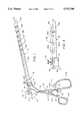
- FIG. 1is a perspective view of a preferred embodiment of the dissector device of the invention, with the outer covering for the dissector portion or element removed;
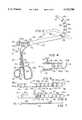
- FIG. 2is a perspective view similar to that of FIG. 1 showing vertical flexure or bending of the distal end of the dissector element in solid lines, and showing two other possible bending positions in dashed lines;
- FIG. 3is a side elevational view, partially broken away, of the dissector element and a portion of the remainder of the device and including the outer covering;
- FIG. 4is a an exploded cross section view of the components shown in FIG. 3;
- FIG. 5is a perspective view of the dissector element of FIG. 1, with parts removed;
- FIG. 6is a top plan view, partially broken away, of the dissector element of FIG. 1;
- FIG. 7is a side elevational view of the control rod or stent for the dissector element.
- FIG. 1there is shown a perspective view of a preferred embodiment of the blunt dissector device of the present invention.
- the devicewhich is generally denoted 10, basically comprises a handle portion 12, a control portion 14 and a finger-like dissector portion 16.
- handle portion 12basically comprises a handle portion 12, a control portion 14 and a finger-like dissector portion 16.
- control portion 14a control portion
- finger-like dissector portion 16As will appear, these designations are more or less arbitrary since, for example, the handle portion performs a control function, and are provided here for ease of description.
- the handle portion 12includes a pair of scissor elements 18 and 20 comprising a pair of elongate legs 18a and 20a terminating at one end on finger grips 18b and 20b and which are pivotably connected together at an intermediate location along the lengths thereof at a pivot element 22.
- a spring 24 disposed between and connected to the legs 18a and 20a distally of pivot elementbiases apart the finger grips or loops 18a and 20a while a locking or latching mechanism, denoted 26, is used to lock the scissor legs in position against the biasing force of spring 24.
- the locking mechanism 26comprises, in the illustrated embodiment, a pair of locking members 28 and 30 disposed on the respective legs 18a and 18b.
- Locking member 28includes a projecting tongue or latch 28a, a portion of which is visible in FIG. 1 and which is adapted to engage in one of a series of laterally spaced grooves 30a formed in locking member 30.
- the pivoting positioni.e., the amount of pivoting, of the scissor elements 18 and 20 is controlled by the groove 30a selected and that this position is releasably locked or latched when tongue or latch 28a is inserted into a selected groove 30a, as shown in FIG. 2.
- the locking or latching mechanism 26can take other forms and that, in general, any locking device or mechanism that will retain the scissor elements 18 and 20 in a selected position can be used.
- the control portion 14 of device 10includes a circular plate member or plate 32 disposed at the other end of scissor element 18 from finger loop or grip 18b.
- Plate 32includes a semicircular aperture 34 therein as well as a central opening 36.
- a control member (rod) or stent 38 including a finger control knob 38aextends through aperture 34 and provides control of the movement of dissector portion 16, as described below.
- a cannula or channel element 40extends through central opening 36 and along the dissector portion 16 to permit the insertion of various instruments required in specific procedures as well as the insertion of a light guide or fiber optic element to enable viewing of the operation site, as is also described below.
- Control rod or stent 38is best seen in FIG. 7 and, as illustrated, includes, in addition to control knob 38a, a non-flexible portion 38' and a flexible portion 38".
- Handle or scissor element 20terminates at the end thereof opposite to finger grip or loop 20b in a cylindrical or barrel member 42 having central cylindrical opening 42a therethrough (see FIG. 4).
- Barrel member 42is offset from the plate 32 and receives the proximal non-flexible end of the dissector portion 16.
- the control rod or stent 38 and the cannula or channel element 40extend through respective openings 38b and 40a in dissector portion 16.
- the dissector portionis freely rotatable within barrel 42 under the control of control rod or stent 38, between the limits defined by semicircular slot or aperture 34.
- barrel 42could be formed by a separate element releasably secured to scissor element 20 by a cylindrical spring or the like fitted around the circumference of barrel 42.
- the proximal, non-flexible end section 16a of dissector portion 16includes a circumferential groove 44 therein which enables a set screw 46 received in an threaded bore or aperture 48 in barrel 42 to engage in groove 44 and thus hold end section 16a in place. In this way the angular position of the dissector portion 16 can be fixed as desired, between the limits defined by semicircular slot 34.
- Dissector portion 16includes, in addition to non-flexible end section 16a, a series of further dissector elements 16b, 16c, 16d, 16e and 16f of like shape and distal or terminating element 16g which has the general shape of the end of a human finger and which includes a recess 50 in the upper (as viewed in FIGS. 1 and 2) surface thereof.
- Elements 16a to 16gare hinged together and, as an example, element 16b hinged to the non-flexible section 16a by a hinge arrangement 52 perhaps best seen in FIG. 5 and FIG. 6 (which is partially broken away to show this).
- Hinge arrangement 52includes a tongue 54 extending from element 16a into a slot or groove 56 in section 16b and held in place by a pin 58. Similar hinge arrangements corresponding to hinge 52 and including tongues 54 and pins 58 are used to connect the remaining elements together.
- the tapered shapes provided by the angled end faces of elements 16b to 16f(perhaps best seen in FIGS. 1, 2 and 5), and the hinging together of the elements described above, enable the elements to pivot about the respective hinges 52 and thus curl or bend away from the straight line or axial position shown in FIG. 1 to the curved position shown in solid lines in FIG. 2 wherein the flexible part of dissector element 16 is curved or curled upwardly.
- This movementis controlled by control rod or stent 38 and more particularly, by handle portion 12.
- plate 32pivots away from barrel 42 and thus causes the fixed end of the flexible portion of control rod 38 to exert a force on the distal end element 16g of dissector portion 16, and to also cause, in the orientation of control rod 38 that is illustrated, elements 16b to 16g to pivot in the same vertical plane to produce the curling or bending effect described above and illustrated in FIG. 2.
- the amount of curvature of the flexible section of dissector portion 16can be controlled by controlling the amount of closure or squeezing together of scissor elements 18a and 20a.
- the desired curvaturecan be "locked in” by virtue of the action of locking mechanism 26 described above.
- dissector 16can also be caused to rotate. Accordingly, if the knob 38a is moved to the endmost portion on the left (as viewed in FIGS. 1 and 2) defined by aperture 34, the flexible portion of dissector element 16 is caused to curl or bend to the left in a horizontal plane containing the fixed portion 16a, as indicated in dashed lines in FIG. 2, and if knob 38a is moved to the right endmost position, the dissector element 16 is caused to bend the to the right in the same plane, as is also indicated in dashed lines.
- the angular position of the dissector element 16can be fixed using set screw 46 which can be screwed into threaded bore 48 to engage in groove 44 in the proximal end of fixed dissector portion 16a and hence inhibit further rotation of the dissector element 16.
- intermediate angular positionscan, of course, be selected as well, depending on the amount of rotation of control rod 38 and thus of dissector 16.
- an outer covering or cuff 60made of silicone or a like material, is used to cover the non-flexible and flexible parts of the dissector element 16 to create a smooth surface and to eliminate or reduce abdominal insufflation in use of the dissector device 10.
- flexing of the flexible part of dissector 16can be carried out without any rotation of the handle portion 12, i.e., with handle portion 12 held stationary.
- the handles 18 and 20can be held by the surgeon in a comfortable position when the dissector portion 16 is rotated so as to direct the tip to the desired angle for dissection.
- Dissection of the anatomical tissueis achieved by suitable flexing (and unflexing) of the flexible part of dissector element 16 through the action of the scissor-like handles 18 and 20, when unlocked. This action is assisted by spring 24 which makes this movement very simple.
- an exemplary length of the flexible part of dissector 16is about 9 to 10 cm.
- the lengthcan vary from 2 to 5 or more centimeters.
- the dissector of the inventionserves to reduce the possibility of unintended perforation of dissected organs such as can occur with prior art devices and procedures and to assist in this, the diameter of the dissector is made relatively large as compared with dissectors presently in use.
- the diameter of the dissectoris on the order of 10 mm.
- the diameter of the dissectorcan be increased if the procedure to be undertaken demands this whereas, on the other hand, the diameter can also be decreased depending on the procedure.
- a small diametere.g., less than about 7 mm.
- the cannula or channel tube 40 provided in the center of the dissector 16may have to be dispensed with because of size considerations.
- the diameter of the dissector element 16is on the order of 5mm to 12 or more mm.
- the channel tube 40can be used to insert a fiber-optic light element, a specifically designed small diameter video camera or various instruments needed for dissection such as scissors, cautering devices, "grasps” and the like.
- the end of channel tube 40is caused to puncture the outer cuff 60 at the distal end to permit this to be done.
- the opening 40b as depicted in FIG. 6 at the tip or distal end of the dissector 16can be used to enable placement of ("hucking" in) the conventional device or drain that is placed around the dissected organ for traction or side manipulation.
Landscapes
- Health & Medical Sciences (AREA)
- Life Sciences & Earth Sciences (AREA)
- Engineering & Computer Science (AREA)
- Public Health (AREA)
- Animal Behavior & Ethology (AREA)
- Veterinary Medicine (AREA)
- General Health & Medical Sciences (AREA)
- Biomedical Technology (AREA)
- Heart & Thoracic Surgery (AREA)
- Hematology (AREA)
- Biophysics (AREA)
- Anesthesiology (AREA)
- Pulmonology (AREA)
- Surgery (AREA)
- Mechanical Engineering (AREA)
- Nuclear Medicine, Radiotherapy & Molecular Imaging (AREA)
- Medical Informatics (AREA)
- Molecular Biology (AREA)
- Surgical Instruments (AREA)
Abstract
Description
Claims (22)
Priority Applications (1)
| Application Number | Priority Date | Filing Date | Title |
|---|---|---|---|
| US08/329,453US5522788A (en) | 1994-10-26 | 1994-10-26 | Finger-like laparoscopic blunt dissector device |
Applications Claiming Priority (1)
| Application Number | Priority Date | Filing Date | Title |
|---|---|---|---|
| US08/329,453US5522788A (en) | 1994-10-26 | 1994-10-26 | Finger-like laparoscopic blunt dissector device |
Publications (1)
| Publication Number | Publication Date |
|---|---|
| US5522788Atrue US5522788A (en) | 1996-06-04 |
Family
ID=23285471
Family Applications (1)
| Application Number | Title | Priority Date | Filing Date |
|---|---|---|---|
| US08/329,453Expired - LifetimeUS5522788A (en) | 1994-10-26 | 1994-10-26 | Finger-like laparoscopic blunt dissector device |
Country Status (1)
| Country | Link |
|---|---|
| US (1) | US5522788A (en) |
Cited By (90)
| Publication number | Priority date | Publication date | Assignee | Title |
|---|---|---|---|---|
| WO1998056297A1 (en)* | 1997-06-11 | 1998-12-17 | Endius Incorporated | Surgical instrument |
| US6036636A (en)* | 1996-11-18 | 2000-03-14 | Olympus Optical Co., Ltd. | Endoscope with tip portion disposed on distal side of insertion portion |
| US6139563A (en)* | 1997-09-25 | 2000-10-31 | Allegiance Corporation | Surgical device with malleable shaft |
| WO2000067642A3 (en)* | 1999-05-06 | 2001-04-26 | Storz Karl Gmbh & Co Kg | Retractor for use in endoscopic surgery |
| US6248062B1 (en)* | 2000-11-09 | 2001-06-19 | Flexbar Machine Corp. | Laparoscopic retractor |
| US6371907B1 (en) | 1996-11-18 | 2002-04-16 | Olympus Optical Co., Ltd. | Endoscope apparatus driving manipulation wires with drive motor in drum portion |
| US6464711B1 (en)* | 1999-03-19 | 2002-10-15 | Medtronic Xomed, Inc. | Articulating mechanism for steerable surgical cutting instruments |
| US6596010B1 (en)* | 1995-05-22 | 2003-07-22 | General Surgical Innovations, Inc. | Balloon dissecting instruments |
| US20030195545A1 (en)* | 1995-05-22 | 2003-10-16 | Hermann George D. | Balloon dissecting instruments |
| US6743239B1 (en)* | 2000-05-25 | 2004-06-01 | St. Jude Medical, Inc. | Devices with a bendable tip for medical procedures |
| US20040225317A1 (en)* | 2003-05-05 | 2004-11-11 | Rehnke Robert D. | Apparatus for use in fascial cleft surgery for opening an anatomic space |
| US20040236316A1 (en)* | 2003-05-23 | 2004-11-25 | Danitz David J. | Articulating mechanism for remote manipulation of a surgical or diagnostic tool |
| US20040243176A1 (en)* | 2001-08-29 | 2004-12-02 | Hahnen Kevin F. | Medical instrument |
| US6858005B2 (en) | 2000-04-03 | 2005-02-22 | Neo Guide Systems, Inc. | Tendon-driven endoscope and methods of insertion |
| US20050090817A1 (en)* | 2003-10-22 | 2005-04-28 | Scimed Life Systems, Inc. | Bendable endoscopic bipolar device |
| US20050107667A1 (en)* | 2003-05-23 | 2005-05-19 | Novare Surgical Systems, Inc. | Hand-actuated device for remote manipulation of a grasping tool |
| US20050131457A1 (en)* | 2003-12-15 | 2005-06-16 | Ethicon, Inc. | Variable stiffness shaft |
| US20050203562A1 (en)* | 2004-03-09 | 2005-09-15 | Palmer Joetta R. | Lighted dissector and method for use |
| US20050203561A1 (en)* | 2004-03-09 | 2005-09-15 | Palmer Joetta R. | Lighted dissector and method for use |
| US20050222601A1 (en)* | 2004-04-06 | 2005-10-06 | Martin Erhard | Laparoscopic instrument |
| US20050273084A1 (en)* | 2004-06-07 | 2005-12-08 | Novare Surgical Systems, Inc. | Link systems and articulation mechanisms for remote manipulation of surgical or diagnostic tools |
| US20050273085A1 (en)* | 2004-06-07 | 2005-12-08 | Novare Surgical Systems, Inc. | Articulating mechanism with flex-hinged links |
| US20060025796A1 (en)* | 2004-07-30 | 2006-02-02 | Regeneration Technologies | Methods and apparatus for minimally invasive recovery of bone and/or other tissue |
| US20060052670A1 (en)* | 2002-10-04 | 2006-03-09 | Stearns Ralph A | Endoscopic retractor |
| US20060094933A1 (en)* | 2004-11-04 | 2006-05-04 | Goldfarb Michael A | Articulated surgical probe and method for use |
| US20060111615A1 (en)* | 2004-11-23 | 2006-05-25 | Novare Surgical Systems, Inc. | Articulating sheath for flexible instruments |
| US20060111210A1 (en)* | 2004-11-23 | 2006-05-25 | Novare Surgical Systems, Inc. | Articulating mechanisms and link systems with torque transmission in remote manipulation of instruments and tools |
| US20060111616A1 (en)* | 2004-11-24 | 2006-05-25 | Novare Surgical Systems, Inc. | Articulating mechanism components and system for easy assembly and disassembly |
| US20060153956A1 (en)* | 2002-12-16 | 2006-07-13 | Bernd Ullmann | Insert for a poressurized container of liquid |
| US20060201130A1 (en)* | 2005-01-31 | 2006-09-14 | Danitz David J | Articulating mechanisms with joint assembly and manual handle for remote manipulation of instruments and tools |
| US20070250113A1 (en)* | 2003-05-23 | 2007-10-25 | Hegeman David E | Tool with articulation lock |
| EP1864625A2 (en) | 2006-06-09 | 2007-12-12 | Ethicon Endo-Surgery, Inc. | Articulating blunt dissector/gastric band application device |
| US20070287993A1 (en)* | 2006-06-13 | 2007-12-13 | Hinman Cameron D | Tool with rotation lock |
| US20080091077A1 (en)* | 2004-11-17 | 2008-04-17 | Satiety, Inc. | Remote tissue retraction device |
| US20080245801A1 (en)* | 2004-07-09 | 2008-10-09 | Bernd Ullmann | Floating Multi-Chambered Insert for Liquid Containers |
| US20080255588A1 (en)* | 2007-04-16 | 2008-10-16 | Hinman Cameron D | Tool with multi-state ratcheted end effector |
| US20080255608A1 (en)* | 2007-04-16 | 2008-10-16 | Hinman Cameron D | Tool with end effector force limiter |
| WO2008131167A1 (en)* | 2007-04-18 | 2008-10-30 | Nmt Medical, Inc. | Flexible catheter system |
| US20080306335A1 (en)* | 2006-06-01 | 2008-12-11 | Origin Medsystems, Inc. | Endoscopic vessel harvesting system components |
| US7507235B2 (en) | 2001-01-13 | 2009-03-24 | Medtronic, Inc. | Method and system for organ positioning and stabilization |
| US7566334B2 (en) | 2004-06-02 | 2009-07-28 | Medtronic, Inc. | Ablation device with jaws |
| US7628780B2 (en) | 2001-01-13 | 2009-12-08 | Medtronic, Inc. | Devices and methods for interstitial injection of biologic agents into tissue |
| US20100041945A1 (en)* | 2008-08-18 | 2010-02-18 | Isbell Jr Lewis | Instrument with articulation lock |
| US20100094315A1 (en)* | 2006-09-08 | 2010-04-15 | Beardsley John W | Dissection Tip And Introducer For Surgical Instrument |
| US7740623B2 (en) | 2001-01-13 | 2010-06-22 | Medtronic, Inc. | Devices and methods for interstitial injection of biologic agents into tissue |
| US7744562B2 (en) | 2003-01-14 | 2010-06-29 | Medtronics, Inc. | Devices and methods for interstitial injection of biologic agents into tissue |
| US7862554B2 (en) | 2007-04-16 | 2011-01-04 | Intuitive Surgical Operations, Inc. | Articulating tool with improved tension member system |
| US7866523B1 (en)* | 2007-09-21 | 2011-01-11 | Cardica, Inc. | Soft-tipped anvil |
| US7871419B2 (en) | 2004-03-03 | 2011-01-18 | Nmt Medical, Inc. | Delivery/recovery system for septal occluder |
| US20110144420A1 (en)* | 2009-12-14 | 2011-06-16 | Woodruff Scott A | Apparatus for Completing Implantation of Gastric Band |
| US7967816B2 (en) | 2002-01-25 | 2011-06-28 | Medtronic, Inc. | Fluid-assisted electrosurgical instrument with shapeable electrode |
| US20110196199A1 (en)* | 2010-02-11 | 2011-08-11 | Intuitive Surgical Operations, Inc. | Method and system for automatically maintaining an operator selected roll orientation at a distal tip of a robotic endoscope |
| US20110257637A1 (en)* | 2008-11-27 | 2011-10-20 | Q Medical International Ag | Instrument for laparoscopic surgery |
| US8062212B2 (en) | 2000-04-03 | 2011-11-22 | Intuitive Surgical Operations, Inc. | Steerable endoscope and improved method of insertion |
| US20120010629A1 (en)* | 2010-07-08 | 2012-01-12 | Warsaw Orthopedic, Inc. | Surgical assembly with flexible arm |
| US8123103B2 (en) | 2003-10-17 | 2012-02-28 | Tyco Healthcare Group Lp | Adaptor for anvil delivery |
| US20120209070A1 (en)* | 2010-10-01 | 2012-08-16 | Cook Medical Technologies Llc | Port access visualization platform |
| US20120220894A1 (en)* | 2009-11-17 | 2012-08-30 | Melsheimer Jeffry S | Deflectable biopsy device |
| US8403196B2 (en) | 2006-09-08 | 2013-03-26 | Covidien Lp | Dissection tip and introducer for surgical instrument |
| US8419720B1 (en) | 2012-02-07 | 2013-04-16 | National Advanced Endoscopy Devices, Incorporated | Flexible laparoscopic device |
| US20140018732A1 (en)* | 2011-01-10 | 2014-01-16 | Spotlight Technology Partners Llc | Apparatus and Methods for Accessing and Treating a Body Cavity, Lumen, or Ostium |
| US20140031611A1 (en)* | 1999-08-12 | 2014-01-30 | Obtech Medical Ag | Anal incontinence disease treatment with controlled wireless energy supply |
| US8647363B2 (en) | 2000-08-30 | 2014-02-11 | Richard A. Hillstead, Inc. | Robotically controlled hydraulic end effector system |
| US8753362B2 (en) | 2003-12-09 | 2014-06-17 | W.L. Gore & Associates, Inc. | Double spiral patent foramen ovale closure clamp |
| US20140319197A1 (en)* | 2003-04-29 | 2014-10-30 | Covidien Lp | Dissecting tip for surgical stapler |
| US8888688B2 (en) | 2000-04-03 | 2014-11-18 | Intuitive Surgical Operations, Inc. | Connector device for a controllable instrument |
| US20150141746A1 (en)* | 2005-04-29 | 2015-05-21 | Ams Research Corporation | Pelvic floor health articles and procedures |
| CN104667413A (en)* | 2015-01-28 | 2015-06-03 | 深圳市科奕顿生物医疗科技有限公司 | Pusher |
| US9101373B2 (en) | 2012-10-15 | 2015-08-11 | Biomet Sports Medicine, Llc | Self-centering drill guide |
| US9161771B2 (en) | 2011-05-13 | 2015-10-20 | Intuitive Surgical Operations Inc. | Medical instrument with snake wrist structure |
| US9221179B2 (en) | 2009-07-23 | 2015-12-29 | Intuitive Surgical Operations, Inc. | Articulating mechanism |
| US9232962B2 (en) | 2009-10-02 | 2016-01-12 | Cook Medical Technologies Llc | Apparatus for single port access |
| US9427282B2 (en) | 2000-04-03 | 2016-08-30 | Intuitive Surgical Operations, Inc. | Apparatus and methods for facilitating treatment of tissue via improved delivery of energy based and non-energy based modalities |
| US9538995B2 (en) | 2012-04-28 | 2017-01-10 | Physcient, Inc. | Methods and devices for soft tissue dissection |
| US9592069B2 (en) | 2012-04-28 | 2017-03-14 | Physcient, Inc. | Methods and devices for soft tissue dissection |
| US9700312B2 (en) | 2014-01-28 | 2017-07-11 | Covidien Lp | Surgical apparatus |
| WO2017156618A1 (en)* | 2016-03-15 | 2017-09-21 | Titan Medical Inc. | Apparatus for removably receiving an end effector for performing surgical operations |
| US9808140B2 (en) | 2000-04-03 | 2017-11-07 | Intuitive Surgical Operations, Inc. | Steerable segmented endoscope and method of insertion |
| US9936952B2 (en) | 2014-02-03 | 2018-04-10 | Covidien Lp | Introducer assembly for a surgical fastener applying apparatus |
| US9936951B2 (en) | 2013-03-12 | 2018-04-10 | Covidien Lp | Interchangeable tip reload |
| US10182843B2 (en) | 2012-03-06 | 2019-01-22 | Phillip A. Williams | Medical device, method and system thereof |
| US10383651B2 (en) | 2014-04-22 | 2019-08-20 | Physcient, Inc. | Instruments, devices, and related methods for soft tissue dissection |
| US10512392B2 (en) | 2008-02-06 | 2019-12-24 | Intuitive Surgical Operations, Inc. | Segmented instrument having braking capabilities |
| US10582942B2 (en) | 2014-04-18 | 2020-03-10 | Physcient, Inc. | Methods and devices for soft tissue dissection |
| US10874412B2 (en) | 2018-08-23 | 2020-12-29 | Titan Medical Inc. | Surgical instrument and removable end effector apparatus |
| US11207098B2 (en)* | 2002-05-16 | 2021-12-28 | Applied Medical Resources Corporation | Blunt tip obturator |
| US20220031324A1 (en)* | 2020-07-28 | 2022-02-03 | Cilag Gmbh International | Surgical instruments with dual spherical articulation joint arrangements |
| US20220142664A1 (en)* | 2019-03-12 | 2022-05-12 | Kosuke UJIHIRA | Minimally-invasive surgery equipment |
| US20220313415A1 (en)* | 2019-06-24 | 2022-10-06 | Ooro Medical Ltd | Device system and method for blunt tissue dissection and stress urinary incontinence treatment |
| EP4463087A4 (en)* | 2022-02-09 | 2025-07-16 | Lsi Solutions Inc | Device for vessel harvesting |
Citations (10)
| Publication number | Priority date | Publication date | Assignee | Title |
|---|---|---|---|---|
| US3730185A (en)* | 1971-10-29 | 1973-05-01 | Cook Inc | Endarterectomy apparatus |
| US4271845A (en)* | 1978-07-01 | 1981-06-09 | Kabushiki Kaisha Medos Kenkyusho | Device for bending a medical instrument inserted into the body cavity |
| US4762120A (en)* | 1983-11-08 | 1988-08-09 | Laserscope, Inc. | Endoscopic device having handle assembly and catheter assembly |
| US4807626A (en)* | 1985-02-14 | 1989-02-28 | Mcgirr Douglas B | Stone extractor and method |
| US4911148A (en)* | 1989-03-14 | 1990-03-27 | Intramed Laboratories, Inc. | Deflectable-end endoscope with detachable flexible shaft assembly |
| US4998527A (en)* | 1989-07-27 | 1991-03-12 | Percutaneous Technologies Inc. | Endoscopic abdominal, urological, and gynecological tissue removing device |
| US5195968A (en)* | 1990-02-02 | 1993-03-23 | Ingemar Lundquist | Catheter steering mechanism |
| US5201752A (en)* | 1990-09-27 | 1993-04-13 | Pod, Inc. | Cholecystectomy dissector instrument |
| US5211655A (en)* | 1992-05-08 | 1993-05-18 | Hasson Harrith M | Multiple use forceps for endoscopy |
| US5284128A (en)* | 1992-01-24 | 1994-02-08 | Applied Medical Resources Corporation | Surgical manipulator |
- 1994
- 1994-10-26USUS08/329,453patent/US5522788A/ennot_activeExpired - Lifetime
Patent Citations (10)
| Publication number | Priority date | Publication date | Assignee | Title |
|---|---|---|---|---|
| US3730185A (en)* | 1971-10-29 | 1973-05-01 | Cook Inc | Endarterectomy apparatus |
| US4271845A (en)* | 1978-07-01 | 1981-06-09 | Kabushiki Kaisha Medos Kenkyusho | Device for bending a medical instrument inserted into the body cavity |
| US4762120A (en)* | 1983-11-08 | 1988-08-09 | Laserscope, Inc. | Endoscopic device having handle assembly and catheter assembly |
| US4807626A (en)* | 1985-02-14 | 1989-02-28 | Mcgirr Douglas B | Stone extractor and method |
| US4911148A (en)* | 1989-03-14 | 1990-03-27 | Intramed Laboratories, Inc. | Deflectable-end endoscope with detachable flexible shaft assembly |
| US4998527A (en)* | 1989-07-27 | 1991-03-12 | Percutaneous Technologies Inc. | Endoscopic abdominal, urological, and gynecological tissue removing device |
| US5195968A (en)* | 1990-02-02 | 1993-03-23 | Ingemar Lundquist | Catheter steering mechanism |
| US5201752A (en)* | 1990-09-27 | 1993-04-13 | Pod, Inc. | Cholecystectomy dissector instrument |
| US5284128A (en)* | 1992-01-24 | 1994-02-08 | Applied Medical Resources Corporation | Surgical manipulator |
| US5211655A (en)* | 1992-05-08 | 1993-05-18 | Hasson Harrith M | Multiple use forceps for endoscopy |
Cited By (230)
| Publication number | Priority date | Publication date | Assignee | Title |
|---|---|---|---|---|
| US7749241B2 (en) | 1995-05-22 | 2010-07-06 | General Surgical Innovations, Inc. | Balloon dissecting instruments |
| US20060058830A1 (en)* | 1995-05-22 | 2006-03-16 | Hermann George D | Balloon dissecting instruments |
| US7037317B2 (en) | 1995-05-22 | 2006-05-02 | United States Surgical Corporation | Balloon dissecting instruments |
| US6596010B1 (en)* | 1995-05-22 | 2003-07-22 | General Surgical Innovations, Inc. | Balloon dissecting instruments |
| US20030195545A1 (en)* | 1995-05-22 | 2003-10-16 | Hermann George D. | Balloon dissecting instruments |
| US6036636A (en)* | 1996-11-18 | 2000-03-14 | Olympus Optical Co., Ltd. | Endoscope with tip portion disposed on distal side of insertion portion |
| US6371907B1 (en) | 1996-11-18 | 2002-04-16 | Olympus Optical Co., Ltd. | Endoscope apparatus driving manipulation wires with drive motor in drum portion |
| DE19748795B4 (en)* | 1996-11-18 | 2006-08-17 | Olympus Corporation | endoscope |
| US5938678A (en)* | 1997-06-11 | 1999-08-17 | Endius Incorporated | Surgical instrument |
| WO1998056297A1 (en)* | 1997-06-11 | 1998-12-17 | Endius Incorporated | Surgical instrument |
| US6139563A (en)* | 1997-09-25 | 2000-10-31 | Allegiance Corporation | Surgical device with malleable shaft |
| US6464711B1 (en)* | 1999-03-19 | 2002-10-15 | Medtronic Xomed, Inc. | Articulating mechanism for steerable surgical cutting instruments |
| WO2000067642A3 (en)* | 1999-05-06 | 2001-04-26 | Storz Karl Gmbh & Co Kg | Retractor for use in endoscopic surgery |
| US6705989B2 (en) | 1999-05-06 | 2004-03-16 | Karl Storz Gmbh & Co. Kg | Retractor for use in endoscopic surgery and medical instrument for introducing a retractor and method for the use of a retractor in endoscopic surgery |
| US20170196670A1 (en)* | 1999-08-12 | 2017-07-13 | Peter Forsell | Anal incontinence disease treatment with controlled wireless energy supply |
| US9439744B2 (en)* | 1999-08-12 | 2016-09-13 | Obtech Medical Ag | Anal incontinence disease treatment with controlled wireless energy supply |
| US10667894B2 (en)* | 1999-08-12 | 2020-06-02 | Peter Forsell | Anal incontinence disease treatment with controlled wireless energy supply |
| US20140031611A1 (en)* | 1999-08-12 | 2014-01-30 | Obtech Medical Ag | Anal incontinence disease treatment with controlled wireless energy supply |
| US8062212B2 (en) | 2000-04-03 | 2011-11-22 | Intuitive Surgical Operations, Inc. | Steerable endoscope and improved method of insertion |
| US9427282B2 (en) | 2000-04-03 | 2016-08-30 | Intuitive Surgical Operations, Inc. | Apparatus and methods for facilitating treatment of tissue via improved delivery of energy based and non-energy based modalities |
| US9808140B2 (en) | 2000-04-03 | 2017-11-07 | Intuitive Surgical Operations, Inc. | Steerable segmented endoscope and method of insertion |
| US10893794B2 (en) | 2000-04-03 | 2021-01-19 | Intuitive Surgical Operations, Inc. | Steerable endoscope and improved method of insertion |
| US8721530B2 (en) | 2000-04-03 | 2014-05-13 | Intuitive Surgical Operations, Inc. | Tendon-driven endoscope and methods of use |
| US11026564B2 (en) | 2000-04-03 | 2021-06-08 | Intuitive Surgical Operations, Inc. | Apparatus and methods for facilitating treatment of tissue via improved delivery of energy based and non-energy based modalities |
| US8827894B2 (en) | 2000-04-03 | 2014-09-09 | Intuitive Surgical Operations, Inc. | Steerable endoscope and improved method of insertion |
| US8834354B2 (en) | 2000-04-03 | 2014-09-16 | Intuitive Surgical Operations, Inc. | Steerable endoscope and improved method of insertion |
| US6858005B2 (en) | 2000-04-03 | 2005-02-22 | Neo Guide Systems, Inc. | Tendon-driven endoscope and methods of insertion |
| US8888688B2 (en) | 2000-04-03 | 2014-11-18 | Intuitive Surgical Operations, Inc. | Connector device for a controllable instrument |
| US12076102B2 (en) | 2000-04-03 | 2024-09-03 | Intuitive Surgical Operations, Inc. | Connector device for a controllable instrument |
| US10327625B2 (en) | 2000-04-03 | 2019-06-25 | Intuitive Surgical Operations, Inc. | Apparatus and methods for facilitating treatment of tissue via improved delivery of energy based and non-energy based modalities |
| US9138132B2 (en) | 2000-04-03 | 2015-09-22 | Intuitive Surgical Operations, Inc. | Steerable endoscope and improved method of insertion |
| US10736490B2 (en) | 2000-04-03 | 2020-08-11 | Intuitive Surgical Operations, Inc. | Connector device for a controllable instrument |
| US10105036B2 (en) | 2000-04-03 | 2018-10-23 | Intuitive Surgical Operations, Inc. | Connector device for a controllable instrument |
| US8641602B2 (en) | 2000-04-03 | 2014-02-04 | Intuitive Surgical Operations, Inc. | Steerable endoscope and improved method of insertion |
| US6743239B1 (en)* | 2000-05-25 | 2004-06-01 | St. Jude Medical, Inc. | Devices with a bendable tip for medical procedures |
| US8647363B2 (en) | 2000-08-30 | 2014-02-11 | Richard A. Hillstead, Inc. | Robotically controlled hydraulic end effector system |
| US6248062B1 (en)* | 2000-11-09 | 2001-06-19 | Flexbar Machine Corp. | Laparoscopic retractor |
| US7740623B2 (en) | 2001-01-13 | 2010-06-22 | Medtronic, Inc. | Devices and methods for interstitial injection of biologic agents into tissue |
| US7628780B2 (en) | 2001-01-13 | 2009-12-08 | Medtronic, Inc. | Devices and methods for interstitial injection of biologic agents into tissue |
| US7507235B2 (en) | 2001-01-13 | 2009-03-24 | Medtronic, Inc. | Method and system for organ positioning and stabilization |
| US8043328B2 (en)* | 2001-08-29 | 2011-10-25 | Richard A. Hillstead, Inc. | Medical instrument |
| US20040243176A1 (en)* | 2001-08-29 | 2004-12-02 | Hahnen Kevin F. | Medical instrument |
| US7967816B2 (en) | 2002-01-25 | 2011-06-28 | Medtronic, Inc. | Fluid-assisted electrosurgical instrument with shapeable electrode |
| US11207098B2 (en)* | 2002-05-16 | 2021-12-28 | Applied Medical Resources Corporation | Blunt tip obturator |
| US20060052670A1 (en)* | 2002-10-04 | 2006-03-09 | Stearns Ralph A | Endoscopic retractor |
| US20060153956A1 (en)* | 2002-12-16 | 2006-07-13 | Bernd Ullmann | Insert for a poressurized container of liquid |
| US8007880B2 (en) | 2002-12-16 | 2011-08-30 | Ball Packaging Europe Gmbh | Insert for a pressurized container of liquid |
| US7744562B2 (en) | 2003-01-14 | 2010-06-29 | Medtronics, Inc. | Devices and methods for interstitial injection of biologic agents into tissue |
| US8273072B2 (en) | 2003-01-14 | 2012-09-25 | Medtronic, Inc. | Devices and methods for interstitial injection of biologic agents into tissue |
| US9522004B2 (en)* | 2003-04-29 | 2016-12-20 | Covidien Lp | Dissecting tip for surgical stapler |
| US20140319197A1 (en)* | 2003-04-29 | 2014-10-30 | Covidien Lp | Dissecting tip for surgical stapler |
| US20080045994A1 (en)* | 2003-05-05 | 2008-02-21 | Rehnke Robert D | Apparatus for use in fascial cleft surgery for opening an anatomic space |
| US7967835B2 (en) | 2003-05-05 | 2011-06-28 | Tyco Healthcare Group Lp | Apparatus for use in fascial cleft surgery for opening an anatomic space |
| US8048087B2 (en) | 2003-05-05 | 2011-11-01 | Tyco Healthcare Group Lp | Apparatus for use in fascial cleft surgery for opening an anatomic space |
| US20040225317A1 (en)* | 2003-05-05 | 2004-11-11 | Rehnke Robert D. | Apparatus for use in fascial cleft surgery for opening an anatomic space |
| US20100262161A1 (en)* | 2003-05-23 | 2010-10-14 | Danitz David J | Articulating instruments with joystick control |
| US9072427B2 (en) | 2003-05-23 | 2015-07-07 | Intuitive Surgical Operations, Inc. | Tool with articulation lock |
| US8535347B2 (en) | 2003-05-23 | 2013-09-17 | Intuitive Surgical Operations, Inc. | Articulating mechanisms with bifurcating control |
| US10342626B2 (en) | 2003-05-23 | 2019-07-09 | Intuitive Surgical Operations, Inc. | Surgical instrument |
| US20050251112A1 (en)* | 2003-05-23 | 2005-11-10 | Danitz David J | Articulating mechanism for remote manipulation of a surgical or diagnostic tool |
| US7682307B2 (en) | 2003-05-23 | 2010-03-23 | Novare Surgical Systems, Inc. | Articulating mechanism for remote manipulation of a surgical or diagnostic tool |
| US7615066B2 (en) | 2003-05-23 | 2009-11-10 | Novare Surgical Systems, Inc. | Articulating mechanism for remote manipulation of a surgical or diagnostic tool |
| US20080262538A1 (en)* | 2003-05-23 | 2008-10-23 | Novare Surgical Systems, Inc. | Articulating instrument |
| US10722314B2 (en) | 2003-05-23 | 2020-07-28 | Intuitive Surgical Operations, Inc. | Articulating retractors |
| US9085085B2 (en) | 2003-05-23 | 2015-07-21 | Intuitive Surgical Operations, Inc. | Articulating mechanisms with actuatable elements |
| US7410483B2 (en) | 2003-05-23 | 2008-08-12 | Novare Surgical Systems, Inc. | Hand-actuated device for remote manipulation of a grasping tool |
| US20050107667A1 (en)* | 2003-05-23 | 2005-05-19 | Novare Surgical Systems, Inc. | Hand-actuated device for remote manipulation of a grasping tool |
| US9370868B2 (en) | 2003-05-23 | 2016-06-21 | Intuitive Surgical Operations, Inc. | Articulating endoscopes |
| US20100261971A1 (en)* | 2003-05-23 | 2010-10-14 | Danitz David J | Articulating retractors |
| US20060094931A1 (en)* | 2003-05-23 | 2006-05-04 | Novare Surgical Systems, Inc. | Articulating mechanism for remote manipulation of a surgical or diagnostic tool |
| US20100262180A1 (en)* | 2003-05-23 | 2010-10-14 | Danitz David J | Articulating mechanisms with bifurcating control |
| US20100261964A1 (en)* | 2003-05-23 | 2010-10-14 | Danitz David J | Articulating endoscopes |
| US20100262075A1 (en)* | 2003-05-23 | 2010-10-14 | Danitz David J | Articulating catheters |
| US9434077B2 (en) | 2003-05-23 | 2016-09-06 | Intuitive Surgical Operations, Inc | Articulating catheters |
| US9737365B2 (en) | 2003-05-23 | 2017-08-22 | Intuitive Surgical Operations, Inc. | Tool with articulation lock |
| US20040236316A1 (en)* | 2003-05-23 | 2004-11-25 | Danitz David J. | Articulating mechanism for remote manipulation of a surgical or diagnostic tool |
| US8100824B2 (en) | 2003-05-23 | 2012-01-24 | Intuitive Surgical Operations, Inc. | Tool with articulation lock |
| US9440364B2 (en) | 2003-05-23 | 2016-09-13 | Intuitive Surgical Operations, Inc. | Articulating instrument |
| US9550300B2 (en) | 2003-05-23 | 2017-01-24 | Intuitive Surgical Operations, Inc. | Articulating retractors |
| US11547287B2 (en) | 2003-05-23 | 2023-01-10 | Intuitive Surgical Operations, Inc. | Surgical instrument |
| US7090637B2 (en) | 2003-05-23 | 2006-08-15 | Novare Surgical Systems, Inc. | Articulating mechanism for remote manipulation of a surgical or diagnostic tool |
| US9498888B2 (en) | 2003-05-23 | 2016-11-22 | Intuitive Surgical Operations, Inc. | Articulating instrument |
| US20070250113A1 (en)* | 2003-05-23 | 2007-10-25 | Hegeman David E | Tool with articulation lock |
| US8365974B2 (en) | 2003-10-17 | 2013-02-05 | Covidien Lp | Surgical stapling device |
| US8123103B2 (en) | 2003-10-17 | 2012-02-28 | Tyco Healthcare Group Lp | Adaptor for anvil delivery |
| US8590763B2 (en) | 2003-10-17 | 2013-11-26 | Covidien Lp | Surgical stapling device |
| US9492168B2 (en) | 2003-10-17 | 2016-11-15 | Covidien Lp | Surgical stapling device |
| US20050090817A1 (en)* | 2003-10-22 | 2005-04-28 | Scimed Life Systems, Inc. | Bendable endoscopic bipolar device |
| US8753362B2 (en) | 2003-12-09 | 2014-06-17 | W.L. Gore & Associates, Inc. | Double spiral patent foramen ovale closure clamp |
| US20050131457A1 (en)* | 2003-12-15 | 2005-06-16 | Ethicon, Inc. | Variable stiffness shaft |
| US8568431B2 (en) | 2004-03-03 | 2013-10-29 | W.L. Gore & Associates, Inc. | Delivery/recovery system for septal occluder |
| US7871419B2 (en) | 2004-03-03 | 2011-01-18 | Nmt Medical, Inc. | Delivery/recovery system for septal occluder |
| US8945158B2 (en) | 2004-03-03 | 2015-02-03 | W.L. Gore & Associates, Inc. | Delivery/recovery system for septal occluder |
| WO2005092200A1 (en)* | 2004-03-09 | 2005-10-06 | Atricure, Inc. | Lighted dissector and method for use |
| WO2005092201A1 (en)* | 2004-03-09 | 2005-10-06 | Atricure, Inc. | Lighted dissector and method for use |
| US20050203562A1 (en)* | 2004-03-09 | 2005-09-15 | Palmer Joetta R. | Lighted dissector and method for use |
| US20050203561A1 (en)* | 2004-03-09 | 2005-09-15 | Palmer Joetta R. | Lighted dissector and method for use |
| US20050222601A1 (en)* | 2004-04-06 | 2005-10-06 | Martin Erhard | Laparoscopic instrument |
| US7566334B2 (en) | 2004-06-02 | 2009-07-28 | Medtronic, Inc. | Ablation device with jaws |
| US7875028B2 (en) | 2004-06-02 | 2011-01-25 | Medtronic, Inc. | Ablation device with jaws |
| US8162941B2 (en) | 2004-06-02 | 2012-04-24 | Medtronic, Inc. | Ablation device with jaws |
| US9095253B2 (en) | 2004-06-07 | 2015-08-04 | Intuitive Surgical Operations, Inc. | Articulating mechanism with flex hinged links |
| US7678117B2 (en) | 2004-06-07 | 2010-03-16 | Novare Surgical Systems, Inc. | Articulating mechanism with flex-hinged links |
| US20100234831A1 (en)* | 2004-06-07 | 2010-09-16 | Hinman Cameron D | Articulating mechanism with flex-hinged links |
| US9517326B2 (en) | 2004-06-07 | 2016-12-13 | Intuitive Surgical Operations, Inc. | Link systems and articulation mechanisms for remote manipulation of surgical or diagnostic tools |
| US9861786B2 (en) | 2004-06-07 | 2018-01-09 | Intuitive Surgical Operations, Inc. | Articulating mechanism with flex hinged links |
| US20100249759A1 (en)* | 2004-06-07 | 2010-09-30 | Cameron Dale Hinman | Link systems and articulation mechanisms for remote manipulation of surgical of diagnostic tools |
| US8920429B2 (en) | 2004-06-07 | 2014-12-30 | Intuitive Surgical Operations, Inc. | Link systems and articulation mechanisms for remote manipulation of surgical or diagnostic tools |
| US11491310B2 (en) | 2004-06-07 | 2022-11-08 | Intuitive Surgical Operations, Inc. | Articulating mechanism with flex-hinged links |
| US20050273085A1 (en)* | 2004-06-07 | 2005-12-08 | Novare Surgical Systems, Inc. | Articulating mechanism with flex-hinged links |
| US8419747B2 (en) | 2004-06-07 | 2013-04-16 | Intuitive Surgical Operations, Inc. | Link systems and articulation mechanisms for remote manipulation of surgical or diagnostic tools |
| US20050273084A1 (en)* | 2004-06-07 | 2005-12-08 | Novare Surgical Systems, Inc. | Link systems and articulation mechanisms for remote manipulation of surgical or diagnostic tools |
| US8323297B2 (en) | 2004-06-07 | 2012-12-04 | Intuitive Surgical Operations, Inc. | Articulating mechanism with flex-hinged links |
| US7828808B2 (en) | 2004-06-07 | 2010-11-09 | Novare Surgical Systems, Inc. | Link systems and articulation mechanisms for remote manipulation of surgical or diagnostic tools |
| US10729885B2 (en) | 2004-06-07 | 2020-08-04 | Intuitive Surgical Operations, Inc. | Articulating mechanism with flex-hinged links |
| US8469221B2 (en) | 2004-07-09 | 2013-06-25 | Ball Packaging Europe Gmbh | Floating multi-chambered insert for liquid containers |
| US20080245801A1 (en)* | 2004-07-09 | 2008-10-09 | Bernd Ullmann | Floating Multi-Chambered Insert for Liquid Containers |
| US20060025796A1 (en)* | 2004-07-30 | 2006-02-02 | Regeneration Technologies | Methods and apparatus for minimally invasive recovery of bone and/or other tissue |
| US20060094932A1 (en)* | 2004-11-04 | 2006-05-04 | Goldfarb Michael A | Articulated surgical probe and method for use |
| US20060094933A1 (en)* | 2004-11-04 | 2006-05-04 | Goldfarb Michael A | Articulated surgical probe and method for use |
| US7963976B2 (en)* | 2004-11-04 | 2011-06-21 | Dynamic Surgical Inventions, Llc | Articulated surgical probe and method for use |
| US7976559B2 (en)* | 2004-11-04 | 2011-07-12 | Dynamic Surgical Inventions, Llc | Articulated surgical probe and method for use |
| US8454503B2 (en) | 2004-11-17 | 2013-06-04 | Ethicon Endo-Surgery, Inc. | Remote tissue retraction device |
| US8403839B2 (en) | 2004-11-17 | 2013-03-26 | Ethicon Endo-Surgery, Inc. | Remote tissue retraction device |
| US8092378B2 (en)* | 2004-11-17 | 2012-01-10 | Ethicon Endo-Surgery, Inc. | Remote tissue retraction device |
| US20080091079A1 (en)* | 2004-11-17 | 2008-04-17 | Satiety, Inc. | Remote tissue retraction device |
| US20080091077A1 (en)* | 2004-11-17 | 2008-04-17 | Satiety, Inc. | Remote tissue retraction device |
| US8403838B2 (en) | 2004-11-17 | 2013-03-26 | Ethicon Endo-Surgery, Inc. | Remote tissue retraction device |
| US8784306B2 (en) | 2004-11-17 | 2014-07-22 | Ethicon Endo-Surgery, Inc. | Remote tissue retraction device |
| US8795166B2 (en) | 2004-11-17 | 2014-08-05 | Ethicon Endo-Surgery, Inc. | Remote tissue retraction device |
| US8939902B2 (en) | 2004-11-17 | 2015-01-27 | Ethicon Endo-Surgery, Inc. | Remote tissue retraction device |
| JP2013081827A (en)* | 2004-11-23 | 2013-05-09 | Intuitive Surgical Operations Inc | Articulating mechanism |
| US7785252B2 (en) | 2004-11-23 | 2010-08-31 | Novare Surgical Systems, Inc. | Articulating sheath for flexible instruments |
| US20110087071A1 (en)* | 2004-11-23 | 2011-04-14 | Intuitive Surgical Operations, Inc. | Articulation sheath for flexible instruments |
| US20060111210A1 (en)* | 2004-11-23 | 2006-05-25 | Novare Surgical Systems, Inc. | Articulating mechanisms and link systems with torque transmission in remote manipulation of instruments and tools |
| US20060111615A1 (en)* | 2004-11-23 | 2006-05-25 | Novare Surgical Systems, Inc. | Articulating sheath for flexible instruments |
| US9700334B2 (en) | 2004-11-23 | 2017-07-11 | Intuitive Surgical Operations, Inc. | Articulating mechanisms and link systems with torque transmission in remote manipulation of instruments and tools |
| US11638590B2 (en) | 2004-11-23 | 2023-05-02 | Intuitive Surgical Operations, Inc. | Articulating mechanisms and link systems with torque transmission in remote manipulation of instruments and tools |
| US9155449B2 (en) | 2004-11-23 | 2015-10-13 | Intuitive Surgical Operations Inc. | Instrument systems and methods of use |
| US10321927B2 (en) | 2004-11-23 | 2019-06-18 | Intuitive Surgical Operations, Inc. | Articulating mechanisms and link systems with torque transmission in remote manipulation of instruments and tools |
| US8277375B2 (en) | 2004-11-23 | 2012-10-02 | Intuitive Surgical Operations, Inc. | Flexible segment system |
| US20060111616A1 (en)* | 2004-11-24 | 2006-05-25 | Novare Surgical Systems, Inc. | Articulating mechanism components and system for easy assembly and disassembly |
| US8182417B2 (en) | 2004-11-24 | 2012-05-22 | Intuitive Surgical Operations, Inc. | Articulating mechanism components and system for easy assembly and disassembly |
| US20060201130A1 (en)* | 2005-01-31 | 2006-09-14 | Danitz David J | Articulating mechanisms with joint assembly and manual handle for remote manipulation of instruments and tools |
| US10028816B2 (en)* | 2005-04-29 | 2018-07-24 | Boston Scientific Scimed, Inc. | Pelvic floor health articles and procedures |
| US20150141746A1 (en)* | 2005-04-29 | 2015-05-21 | Ams Research Corporation | Pelvic floor health articles and procedures |
| US11141055B2 (en) | 2006-06-01 | 2021-10-12 | Maquet Cardiovascular Llc | Endoscopic vessel harvesting system components |
| US11134835B2 (en) | 2006-06-01 | 2021-10-05 | Maquet Cardiovascular Llc | Endoscopic vessel harvesting system components |
| US20080306335A1 (en)* | 2006-06-01 | 2008-12-11 | Origin Medsystems, Inc. | Endoscopic vessel harvesting system components |
| US9770230B2 (en)* | 2006-06-01 | 2017-09-26 | Maquet Cardiovascular Llc | Endoscopic vessel harvesting system components |
| US10299770B2 (en) | 2006-06-01 | 2019-05-28 | Maquet Cardiovascular Llc | Endoscopic vessel harvesting system components |
| EP1864625A2 (en) | 2006-06-09 | 2007-12-12 | Ethicon Endo-Surgery, Inc. | Articulating blunt dissector/gastric band application device |
| US20070287993A1 (en)* | 2006-06-13 | 2007-12-13 | Hinman Cameron D | Tool with rotation lock |
| US9561045B2 (en) | 2006-06-13 | 2017-02-07 | Intuitive Surgical Operations, Inc. | Tool with rotation lock |
| US8136711B2 (en) | 2006-09-08 | 2012-03-20 | Tyco Healthcare Group Lp | Dissection tip and introducer for surgical instrument |
| US11123066B2 (en) | 2006-09-08 | 2021-09-21 | Covidien Lp | Dissection tip and introducer for surgical instrument |
| US9433416B2 (en) | 2006-09-08 | 2016-09-06 | Covidien Lp | Dissection tip and introducer for surgical instrument |
| US8690039B2 (en) | 2006-09-08 | 2014-04-08 | Covidien Lp | Dissection tip and introducer for surgical instrument |
| US8403196B2 (en) | 2006-09-08 | 2013-03-26 | Covidien Lp | Dissection tip and introducer for surgical instrument |
| US10080564B2 (en) | 2006-09-08 | 2018-09-25 | Covidien Lp | Dissection tip and introducer for surgical instrument |
| US8403195B2 (en) | 2006-09-08 | 2013-03-26 | Coviden Lp | Dissection tip and introducer for surgical instrument |
| US20100094315A1 (en)* | 2006-09-08 | 2010-04-15 | Beardsley John W | Dissection Tip And Introducer For Surgical Instrument |
| US20080255608A1 (en)* | 2007-04-16 | 2008-10-16 | Hinman Cameron D | Tool with end effector force limiter |
| US7862554B2 (en) | 2007-04-16 | 2011-01-04 | Intuitive Surgical Operations, Inc. | Articulating tool with improved tension member system |
| US20080255588A1 (en)* | 2007-04-16 | 2008-10-16 | Hinman Cameron D | Tool with multi-state ratcheted end effector |
| US8562640B2 (en) | 2007-04-16 | 2013-10-22 | Intuitive Surgical Operations, Inc. | Tool with multi-state ratcheted end effector |
| US8409244B2 (en) | 2007-04-16 | 2013-04-02 | Intuitive Surgical Operations, Inc. | Tool with end effector force limiter |
| WO2008131167A1 (en)* | 2007-04-18 | 2008-10-30 | Nmt Medical, Inc. | Flexible catheter system |
| US9138562B2 (en) | 2007-04-18 | 2015-09-22 | W.L. Gore & Associates, Inc. | Flexible catheter system |
| US8398653B2 (en) | 2007-09-21 | 2013-03-19 | Cardica, Inc. | Surgical method utilizing a soft-tipped anvil |
| US7866523B1 (en)* | 2007-09-21 | 2011-01-11 | Cardica, Inc. | Soft-tipped anvil |
| US10952594B2 (en) | 2008-02-06 | 2021-03-23 | Intuitive Surgical Operations, Inc. | Segmented instrument having braking capabilities |
| US10512392B2 (en) | 2008-02-06 | 2019-12-24 | Intuitive Surgical Operations, Inc. | Segmented instrument having braking capabilities |
| US9737298B2 (en) | 2008-08-18 | 2017-08-22 | Intuitive Surgical Operations, Inc. | Instrument with articulation lock |
| US11234694B2 (en) | 2008-08-18 | 2022-02-01 | Intuitive Surgical Operations, Inc. | Instrument with multiple articulation locks |
| US9033960B2 (en) | 2008-08-18 | 2015-05-19 | Intuitive Surgical Operations, Inc. | Instrument with multiple articulation locks |
| US8465475B2 (en) | 2008-08-18 | 2013-06-18 | Intuitive Surgical Operations, Inc. | Instrument with multiple articulation locks |
| US11998195B2 (en) | 2008-08-18 | 2024-06-04 | Intuitive Surgical Operations, Inc. | Instrument with multiple articulation locks |
| US20100041945A1 (en)* | 2008-08-18 | 2010-02-18 | Isbell Jr Lewis | Instrument with articulation lock |
| US8932277B2 (en)* | 2008-11-27 | 2015-01-13 | Q Medical International Ag | Instrument for laparoscopic surgery |
| US20110257637A1 (en)* | 2008-11-27 | 2011-10-20 | Q Medical International Ag | Instrument for laparoscopic surgery |
| US9221179B2 (en) | 2009-07-23 | 2015-12-29 | Intuitive Surgical Operations, Inc. | Articulating mechanism |
| US10076239B2 (en) | 2009-10-02 | 2018-09-18 | Cook Medical Technologies Llc | Port access visualization platform |
| US9232962B2 (en) | 2009-10-02 | 2016-01-12 | Cook Medical Technologies Llc | Apparatus for single port access |
| US20120220894A1 (en)* | 2009-11-17 | 2012-08-30 | Melsheimer Jeffry S | Deflectable biopsy device |
| US9247929B2 (en)* | 2009-11-17 | 2016-02-02 | Cook Medical Technologies Llc | Deflectable biopsy device |
| US20110144420A1 (en)* | 2009-12-14 | 2011-06-16 | Woodruff Scott A | Apparatus for Completing Implantation of Gastric Band |
| US8968180B2 (en) | 2009-12-14 | 2015-03-03 | Ethicon Endo-Surgery, Inc. | Apparatus for completing implantation of gastric band |
| WO2011075338A1 (en) | 2009-12-14 | 2011-06-23 | Ethicon Endo-Surgery, Inc. | Apparatus for completing implantation of gastric band |
| US9039608B2 (en) | 2010-02-11 | 2015-05-26 | Intuituve Surgical Operations, Inc. | Method and system for automatically maintaining an operator selected roll orientation at a distal tip of a robotic endoscope |
| US8668638B2 (en) | 2010-02-11 | 2014-03-11 | Intuitive Surgical Operations, Inc. | Method and system for automatically maintaining an operator selected roll orientation at a distal tip of a robotic endoscope |
| US20110196199A1 (en)* | 2010-02-11 | 2011-08-11 | Intuitive Surgical Operations, Inc. | Method and system for automatically maintaining an operator selected roll orientation at a distal tip of a robotic endoscope |
| US9486296B2 (en)* | 2010-07-08 | 2016-11-08 | Warsaw Orthopedic, Inc. | Surgical assembly with flexible arm |
| US20160331392A1 (en)* | 2010-07-08 | 2016-11-17 | Warsaw Orthopedic Inc. | Surgical assembly with flexible arm |
| US20120010629A1 (en)* | 2010-07-08 | 2012-01-12 | Warsaw Orthopedic, Inc. | Surgical assembly with flexible arm |
| US10238409B2 (en)* | 2010-07-08 | 2019-03-26 | Warsaw Orthopedic, Inc. | Surgical assembly with flexible arm |
| US20120209070A1 (en)* | 2010-10-01 | 2012-08-16 | Cook Medical Technologies Llc | Port access visualization platform |
| US9339264B2 (en)* | 2010-10-01 | 2016-05-17 | Cook Medical Technologies Llc | Port access visualization platform |
| US20140018732A1 (en)* | 2011-01-10 | 2014-01-16 | Spotlight Technology Partners Llc | Apparatus and Methods for Accessing and Treating a Body Cavity, Lumen, or Ostium |
| US9161771B2 (en) | 2011-05-13 | 2015-10-20 | Intuitive Surgical Operations Inc. | Medical instrument with snake wrist structure |
| US11357526B2 (en) | 2011-05-13 | 2022-06-14 | Intuitive Surgical Operations, Inc. | Medical instrument with snake wrist structure |
| US10335177B2 (en) | 2011-05-13 | 2019-07-02 | Intuitive Surgical Operations, Inc. | Medical instrument with snake wrist structure |
| US8419720B1 (en) | 2012-02-07 | 2013-04-16 | National Advanced Endoscopy Devices, Incorporated | Flexible laparoscopic device |
| US11793547B2 (en) | 2012-03-06 | 2023-10-24 | Southwest Gynmed, Llc | Medical device, method and system thereof |
| US11026720B2 (en) | 2012-03-06 | 2021-06-08 | Phillip A. Williams | Medical device, method and system thereof |
| US10182843B2 (en) | 2012-03-06 | 2019-01-22 | Phillip A. Williams | Medical device, method and system thereof |
| US10639056B2 (en) | 2012-04-28 | 2020-05-05 | Physcient, Inc. | Methods and devices for soft tissue dissection |
| US9592069B2 (en) | 2012-04-28 | 2017-03-14 | Physcient, Inc. | Methods and devices for soft tissue dissection |
| US9538995B2 (en) | 2012-04-28 | 2017-01-10 | Physcient, Inc. | Methods and devices for soft tissue dissection |
| US11253283B2 (en) | 2012-04-28 | 2022-02-22 | Physcient, Inc. | Methods and devices for soft tissue dissection |
| US9101373B2 (en) | 2012-10-15 | 2015-08-11 | Biomet Sports Medicine, Llc | Self-centering drill guide |
| US9936951B2 (en) | 2013-03-12 | 2018-04-10 | Covidien Lp | Interchangeable tip reload |
| US11331097B2 (en) | 2014-01-28 | 2022-05-17 | Covidien Lp | Surgical apparatus |
| US9700312B2 (en) | 2014-01-28 | 2017-07-11 | Covidien Lp | Surgical apparatus |
| US10582927B2 (en) | 2014-01-28 | 2020-03-10 | Covidien Lp | Surgical apparatus |
| US9936952B2 (en) | 2014-02-03 | 2018-04-10 | Covidien Lp | Introducer assembly for a surgical fastener applying apparatus |
| US10582942B2 (en) | 2014-04-18 | 2020-03-10 | Physcient, Inc. | Methods and devices for soft tissue dissection |
| US10383651B2 (en) | 2014-04-22 | 2019-08-20 | Physcient, Inc. | Instruments, devices, and related methods for soft tissue dissection |
| CN104667413A (en)* | 2015-01-28 | 2015-06-03 | 深圳市科奕顿生物医疗科技有限公司 | Pusher |
| WO2017156618A1 (en)* | 2016-03-15 | 2017-09-21 | Titan Medical Inc. | Apparatus for removably receiving an end effector for performing surgical operations |
| US11357528B2 (en) | 2016-03-15 | 2022-06-14 | Titan Medical Inc. | Apparatus for removably receiving an end effector for performing surgical operations |
| US10835275B2 (en) | 2016-03-15 | 2020-11-17 | Titan Medical Inc. | Apparatus for removably receiving an end effector for performing surgical operations |
| US10874412B2 (en) | 2018-08-23 | 2020-12-29 | Titan Medical Inc. | Surgical instrument and removable end effector apparatus |
| US12004764B2 (en) | 2018-08-23 | 2024-06-11 | Covidien Lp | Surgical instrument and removable end effector apparatus |
| US11642148B2 (en)* | 2019-03-12 | 2023-05-09 | Kosuke Ujihira | Minimally-invasive surgery equipment |
| US20220142664A1 (en)* | 2019-03-12 | 2022-05-12 | Kosuke UJIHIRA | Minimally-invasive surgery equipment |
| US20220313415A1 (en)* | 2019-06-24 | 2022-10-06 | Ooro Medical Ltd | Device system and method for blunt tissue dissection and stress urinary incontinence treatment |
| US11871925B2 (en)* | 2020-07-28 | 2024-01-16 | Cilag Gmbh International | Surgical instruments with dual spherical articulation joint arrangements |
| US20220031324A1 (en)* | 2020-07-28 | 2022-02-03 | Cilag Gmbh International | Surgical instruments with dual spherical articulation joint arrangements |
| EP4463087A4 (en)* | 2022-02-09 | 2025-07-16 | Lsi Solutions Inc | Device for vessel harvesting |
Similar Documents
| Publication | Publication Date | Title |
|---|---|---|
| US5522788A (en) | Finger-like laparoscopic blunt dissector device | |
| US10188372B2 (en) | Surgical instrument guide device | |
| US5511564A (en) | Laparoscopic stretching instrument and associated method | |
| US5860995A (en) | Laparoscopic endoscopic surgical instrument | |
| US5395367A (en) | Laparoscopic instrument with bendable shaft and removable actuator | |
| US5797939A (en) | Endoscopic scissors with longitudinal operating channel | |
| US5797958A (en) | Endoscopic grasping instrument with scissors | |
| ES2383269T3 (en) | Medical instrument | |
| US8409175B2 (en) | Surgical instrument guide device | |
| US5984939A (en) | Multifunctional grasping instrument with cutting member and operating channel for use in endoscopic and non-endoscopic procedures | |
| US5209747A (en) | Adjustable angle medical forceps | |
| US5772670A (en) | Forceps for the surgical introduction of catheters and the like | |
| US5899854A (en) | Speculum and method for inserting an elongated instrument into an animal's body | |
| US8409245B2 (en) | Surgical instrument | |
| US5467763A (en) | Surgical instruments | |
| JP5009251B2 (en) | Arthroscopic instruments | |
| EP0623004B1 (en) | Surgical instruments | |
| US20130053877A1 (en) | Multiple Function Surgical Instrument | |
| US20100249497A1 (en) | Surgical instrument | |
| EP2016908A2 (en) | Suturing articulating device for tissue and needle manipulation during minimally invasive endoscopic procedure | |
| US5993461A (en) | Laparoscopic instrument for manipulating the uterus during laparoscopic surgery | |
| US6454762B1 (en) | Instrument for applying light, especially laser light, to the human or animal body | |
| EP0630211A4 (en) | Surgical retractor and surgical method. | |
| JPH10174689A (en) | Surgical tool for endoscope | |
| US20110238108A1 (en) | Surgical instrument |
Legal Events
| Date | Code | Title | Description |
|---|---|---|---|
| FEPP | Fee payment procedure | Free format text:PAYOR NUMBER ASSIGNED (ORIGINAL EVENT CODE: ASPN); ENTITY STATUS OF PATENT OWNER: SMALL ENTITY | |
| STCF | Information on status: patent grant | Free format text:PATENTED CASE | |
| FEPP | Fee payment procedure | Free format text:PAYER NUMBER DE-ASSIGNED (ORIGINAL EVENT CODE: RMPN); ENTITY STATUS OF PATENT OWNER: SMALL ENTITY Free format text:PAYOR NUMBER ASSIGNED (ORIGINAL EVENT CODE: ASPN); ENTITY STATUS OF PATENT OWNER: SMALL ENTITY | |
| FPAY | Fee payment | Year of fee payment:4 | |
| AS | Assignment | Owner name:ETHICON ENDO-SURGERY, INC., OHIO Free format text:ASSIGNMENT OF ASSIGNORS INTEREST;ASSIGNOR:KUZMAK, LUBOMYR I;REEL/FRAME:012365/0792 Effective date:20011127 | |
| FPAY | Fee payment | Year of fee payment:8 | |
| AS | Assignment | Owner name:GENERAL ELECTRIC CAPITAL CORPORATION, NEW YORK Free format text:SECURITY AGREEMENT;ASSIGNOR:EXOPAC ADVANCED COATING, LLC;REEL/FRAME:020083/0138 Effective date:20071031 | |
| FPAY | Fee payment | Year of fee payment:12 |