US5522089A - Personal digital assistant module adapted for initiating telephone communications through DTMF dialing - Google Patents
Personal digital assistant module adapted for initiating telephone communications through DTMF dialingDownload PDFInfo
- Publication number
- US5522089A US5522089AUS08/304,266US30426694AUS5522089AUS 5522089 AUS5522089 AUS 5522089AUS 30426694 AUS30426694 AUS 30426694AUS 5522089 AUS5522089 AUS 5522089A
- Authority
- US
- United States
- Prior art keywords
- μpda
- host
- digital assistant
- user
- interface
- Prior art date
- Legal status (The legal status is an assumption and is not a legal conclusion. Google has not performed a legal analysis and makes no representation as to the accuracy of the status listed.)
- Expired - Lifetime
Links
Images


Classifications
- G—PHYSICS
- G06—COMPUTING OR CALCULATING; COUNTING
- G06F—ELECTRIC DIGITAL DATA PROCESSING
- G06F1/00—Details not covered by groups G06F3/00 - G06F13/00 and G06F21/00
- G06F1/16—Constructional details or arrangements
- G06F1/1613—Constructional details or arrangements for portable computers
- G06F1/1633—Constructional details or arrangements of portable computers not specific to the type of enclosures covered by groups G06F1/1615 - G06F1/1626
- G06F1/1656—Details related to functional adaptations of the enclosure, e.g. to provide protection against EMI, shock, water, or to host detachable peripherals like a mouse or removable expansions units like PCMCIA cards, or to provide access to internal components for maintenance or to removable storage supports like CDs or DVDs, or to mechanically mount accessories
- G—PHYSICS
- G06—COMPUTING OR CALCULATING; COUNTING
- G06F—ELECTRIC DIGITAL DATA PROCESSING
- G06F1/00—Details not covered by groups G06F3/00 - G06F13/00 and G06F21/00
- G06F1/16—Constructional details or arrangements
- G06F1/1613—Constructional details or arrangements for portable computers
- G06F1/1615—Constructional details or arrangements for portable computers with several enclosures having relative motions, each enclosure supporting at least one I/O or computing function
- G06F1/1616—Constructional details or arrangements for portable computers with several enclosures having relative motions, each enclosure supporting at least one I/O or computing function with folding flat displays, e.g. laptop computers or notebooks having a clamshell configuration, with body parts pivoting to an open position around an axis parallel to the plane they define in closed position
- G—PHYSICS
- G06—COMPUTING OR CALCULATING; COUNTING
- G06F—ELECTRIC DIGITAL DATA PROCESSING
- G06F1/00—Details not covered by groups G06F3/00 - G06F13/00 and G06F21/00
- G06F1/16—Constructional details or arrangements
- G06F1/1613—Constructional details or arrangements for portable computers
- G06F1/1626—Constructional details or arrangements for portable computers with a single-body enclosure integrating a flat display, e.g. Personal Digital Assistants [PDAs]
- G—PHYSICS
- G06—COMPUTING OR CALCULATING; COUNTING
- G06F—ELECTRIC DIGITAL DATA PROCESSING
- G06F1/00—Details not covered by groups G06F3/00 - G06F13/00 and G06F21/00
- G06F1/16—Constructional details or arrangements
- G06F1/1613—Constructional details or arrangements for portable computers
- G06F1/1632—External expansion units, e.g. docking stations
- G—PHYSICS
- G06—COMPUTING OR CALCULATING; COUNTING
- G06F—ELECTRIC DIGITAL DATA PROCESSING
- G06F1/00—Details not covered by groups G06F3/00 - G06F13/00 and G06F21/00
- G06F1/16—Constructional details or arrangements
- G06F1/1613—Constructional details or arrangements for portable computers
- G06F1/1633—Constructional details or arrangements of portable computers not specific to the type of enclosures covered by groups G06F1/1615 - G06F1/1626
- G06F1/1635—Details related to the integration of battery packs and other power supplies such as fuel cells or integrated AC adapter
- G—PHYSICS
- G06—COMPUTING OR CALCULATING; COUNTING
- G06F—ELECTRIC DIGITAL DATA PROCESSING
- G06F1/00—Details not covered by groups G06F3/00 - G06F13/00 and G06F21/00
- G06F1/16—Constructional details or arrangements
- G06F1/1613—Constructional details or arrangements for portable computers
- G06F1/1633—Constructional details or arrangements of portable computers not specific to the type of enclosures covered by groups G06F1/1615 - G06F1/1626
- G06F1/1684—Constructional details or arrangements related to integrated I/O peripherals not covered by groups G06F1/1635 - G06F1/1675
- G06F1/1688—Constructional details or arrangements related to integrated I/O peripherals not covered by groups G06F1/1635 - G06F1/1675 the I/O peripheral being integrated loudspeakers
- G—PHYSICS
- G06—COMPUTING OR CALCULATING; COUNTING
- G06F—ELECTRIC DIGITAL DATA PROCESSING
- G06F1/00—Details not covered by groups G06F3/00 - G06F13/00 and G06F21/00
- G06F1/16—Constructional details or arrangements
- G06F1/1613—Constructional details or arrangements for portable computers
- G06F1/1633—Constructional details or arrangements of portable computers not specific to the type of enclosures covered by groups G06F1/1615 - G06F1/1626
- G06F1/1684—Constructional details or arrangements related to integrated I/O peripherals not covered by groups G06F1/1635 - G06F1/1675
- G06F1/169—Constructional details or arrangements related to integrated I/O peripherals not covered by groups G06F1/1635 - G06F1/1675 the I/O peripheral being an integrated pointing device, e.g. trackball in the palm rest area, mini-joystick integrated between keyboard keys, touch pads or touch stripes
- G—PHYSICS
- G06—COMPUTING OR CALCULATING; COUNTING
- G06F—ELECTRIC DIGITAL DATA PROCESSING
- G06F1/00—Details not covered by groups G06F3/00 - G06F13/00 and G06F21/00
- G06F1/16—Constructional details or arrangements
- G06F1/18—Packaging or power distribution
- G06F1/183—Internal mounting support structures, e.g. for printed circuit boards, internal connecting means
- G—PHYSICS
- G06—COMPUTING OR CALCULATING; COUNTING
- G06F—ELECTRIC DIGITAL DATA PROCESSING
- G06F1/00—Details not covered by groups G06F3/00 - G06F13/00 and G06F21/00
- G06F1/16—Constructional details or arrangements
- G06F1/20—Cooling means
- G06F1/203—Cooling means for portable computers, e.g. for laptops
- G—PHYSICS
- G06—COMPUTING OR CALCULATING; COUNTING
- G06F—ELECTRIC DIGITAL DATA PROCESSING
- G06F1/00—Details not covered by groups G06F3/00 - G06F13/00 and G06F21/00
- G06F1/16—Constructional details or arrangements
- G06F1/20—Cooling means
- G06F1/206—Cooling means comprising thermal management
- G—PHYSICS
- G06—COMPUTING OR CALCULATING; COUNTING
- G06F—ELECTRIC DIGITAL DATA PROCESSING
- G06F13/00—Interconnection of, or transfer of information or other signals between, memories, input/output devices or central processing units
- G06F13/38—Information transfer, e.g. on bus
- G06F13/40—Bus structure
- G06F13/4063—Device-to-bus coupling
- G06F13/409—Mechanical coupling
- G—PHYSICS
- G06—COMPUTING OR CALCULATING; COUNTING
- G06F—ELECTRIC DIGITAL DATA PROCESSING
- G06F15/00—Digital computers in general; Data processing equipment in general
- G06F15/02—Digital computers in general; Data processing equipment in general manually operated with input through keyboard and computation using a built-in program, e.g. pocket calculators
- G06F15/0225—User interface arrangements, e.g. keyboard, display; Interfaces to other computer systems
- G—PHYSICS
- G06—COMPUTING OR CALCULATING; COUNTING
- G06F—ELECTRIC DIGITAL DATA PROCESSING
- G06F21/00—Security arrangements for protecting computers, components thereof, programs or data against unauthorised activity
- G06F21/30—Authentication, i.e. establishing the identity or authorisation of security principals
- G06F21/31—User authentication
- G—PHYSICS
- G06—COMPUTING OR CALCULATING; COUNTING
- G06F—ELECTRIC DIGITAL DATA PROCESSING
- G06F21/00—Security arrangements for protecting computers, components thereof, programs or data against unauthorised activity
- G06F21/60—Protecting data
- G06F21/62—Protecting access to data via a platform, e.g. using keys or access control rules
- G—PHYSICS
- G06—COMPUTING OR CALCULATING; COUNTING
- G06F—ELECTRIC DIGITAL DATA PROCESSING
- G06F3/00—Input arrangements for transferring data to be processed into a form capable of being handled by the computer; Output arrangements for transferring data from processing unit to output unit, e.g. interface arrangements
- G06F3/01—Input arrangements or combined input and output arrangements for interaction between user and computer
- G06F3/048—Interaction techniques based on graphical user interfaces [GUI]
- G06F3/0481—Interaction techniques based on graphical user interfaces [GUI] based on specific properties of the displayed interaction object or a metaphor-based environment, e.g. interaction with desktop elements like windows or icons, or assisted by a cursor's changing behaviour or appearance
- G06F3/0482—Interaction with lists of selectable items, e.g. menus
- G—PHYSICS
- G06—COMPUTING OR CALCULATING; COUNTING
- G06F—ELECTRIC DIGITAL DATA PROCESSING
- G06F3/00—Input arrangements for transferring data to be processed into a form capable of being handled by the computer; Output arrangements for transferring data from processing unit to output unit, e.g. interface arrangements
- G06F3/16—Sound input; Sound output
- H—ELECTRICITY
- H04—ELECTRIC COMMUNICATION TECHNIQUE
- H04L—TRANSMISSION OF DIGITAL INFORMATION, e.g. TELEGRAPHIC COMMUNICATION
- H04L63/00—Network architectures or network communication protocols for network security
- H04L63/10—Network architectures or network communication protocols for network security for controlling access to devices or network resources
- H—ELECTRICITY
- H04—ELECTRIC COMMUNICATION TECHNIQUE
- H04M—TELEPHONIC COMMUNICATION
- H04M1/00—Substation equipment, e.g. for use by subscribers
- H04M1/26—Devices for calling a subscriber
- H04M1/27—Devices whereby a plurality of signals may be stored simultaneously
- H—ELECTRICITY
- H04—ELECTRIC COMMUNICATION TECHNIQUE
- H04M—TELEPHONIC COMMUNICATION
- H04M1/00—Substation equipment, e.g. for use by subscribers
- H04M1/26—Devices for calling a subscriber
- H04M1/27—Devices whereby a plurality of signals may be stored simultaneously
- H04M1/274—Devices whereby a plurality of signals may be stored simultaneously with provision for storing more than one subscriber number at a time, e.g. using toothed disc
- H04M1/2745—Devices whereby a plurality of signals may be stored simultaneously with provision for storing more than one subscriber number at a time, e.g. using toothed disc using static electronic memories, e.g. chips
- H04M1/275—Devices whereby a plurality of signals may be stored simultaneously with provision for storing more than one subscriber number at a time, e.g. using toothed disc using static electronic memories, e.g. chips implemented by means of portable electronic directories
- H—ELECTRICITY
- H04—ELECTRIC COMMUNICATION TECHNIQUE
- H04M—TELEPHONIC COMMUNICATION
- H04M1/00—Substation equipment, e.g. for use by subscribers
- H04M1/26—Devices for calling a subscriber
- H04M1/30—Devices which can set up and transmit only one digit at a time
- H04M1/50—Devices which can set up and transmit only one digit at a time by generating or selecting currents of predetermined frequencies or combinations of frequencies
- H04M1/505—Devices which can set up and transmit only one digit at a time by generating or selecting currents of predetermined frequencies or combinations of frequencies signals generated in digital form
- H—ELECTRICITY
- H04—ELECTRIC COMMUNICATION TECHNIQUE
- H04M—TELEPHONIC COMMUNICATION
- H04M1/00—Substation equipment, e.g. for use by subscribers
- H04M1/72—Mobile telephones; Cordless telephones, i.e. devices for establishing wireless links to base stations without route selection
- H04M1/724—User interfaces specially adapted for cordless or mobile telephones
- H04M1/72403—User interfaces specially adapted for cordless or mobile telephones with means for local support of applications that increase the functionality
- H04M1/72409—User interfaces specially adapted for cordless or mobile telephones with means for local support of applications that increase the functionality by interfacing with external accessories
- H04M1/72415—User interfaces specially adapted for cordless or mobile telephones with means for local support of applications that increase the functionality by interfacing with external accessories for remote control of appliances
- H—ELECTRICITY
- H04—ELECTRIC COMMUNICATION TECHNIQUE
- H04M—TELEPHONIC COMMUNICATION
- H04M1/00—Substation equipment, e.g. for use by subscribers
- H04M1/72—Mobile telephones; Cordless telephones, i.e. devices for establishing wireless links to base stations without route selection
- H04M1/725—Cordless telephones
- H—ELECTRICITY
- H04—ELECTRIC COMMUNICATION TECHNIQUE
- H04M—TELEPHONIC COMMUNICATION
- H04M11/00—Telephonic communication systems specially adapted for combination with other electrical systems
- H04M11/06—Simultaneous speech and data transmission, e.g. telegraphic transmission over the same conductors
- H04M11/066—Telephone sets adapted for data transmision
- H—ELECTRICITY
- H04—ELECTRIC COMMUNICATION TECHNIQUE
- H04M—TELEPHONIC COMMUNICATION
- H04M3/00—Automatic or semi-automatic exchanges
- H04M3/42—Systems providing special services or facilities to subscribers
- H04M3/42314—Systems providing special services or facilities to subscribers in private branch exchanges
- H—ELECTRICITY
- H04—ELECTRIC COMMUNICATION TECHNIQUE
- H04N—PICTORIAL COMMUNICATION, e.g. TELEVISION
- H04N1/00—Scanning, transmission or reproduction of documents or the like, e.g. facsimile transmission; Details thereof
- H04N1/00127—Connection or combination of a still picture apparatus with another apparatus, e.g. for storage, processing or transmission of still picture signals or of information associated with a still picture
- H04N1/00204—Connection or combination of a still picture apparatus with another apparatus, e.g. for storage, processing or transmission of still picture signals or of information associated with a still picture with a digital computer or a digital computer system, e.g. an internet server
- H04N1/00236—Connection or combination of a still picture apparatus with another apparatus, e.g. for storage, processing or transmission of still picture signals or of information associated with a still picture with a digital computer or a digital computer system, e.g. an internet server using an image reading or reproducing device, e.g. a facsimile reader or printer, as a local input to or local output from a computer
- H04N1/00241—Connection or combination of a still picture apparatus with another apparatus, e.g. for storage, processing or transmission of still picture signals or of information associated with a still picture with a digital computer or a digital computer system, e.g. an internet server using an image reading or reproducing device, e.g. a facsimile reader or printer, as a local input to or local output from a computer using an image reading device as a local input to a computer
- H—ELECTRICITY
- H04—ELECTRIC COMMUNICATION TECHNIQUE
- H04N—PICTORIAL COMMUNICATION, e.g. TELEVISION
- H04N1/00—Scanning, transmission or reproduction of documents or the like, e.g. facsimile transmission; Details thereof
- H04N1/00127—Connection or combination of a still picture apparatus with another apparatus, e.g. for storage, processing or transmission of still picture signals or of information associated with a still picture
- H04N1/00326—Connection or combination of a still picture apparatus with another apparatus, e.g. for storage, processing or transmission of still picture signals or of information associated with a still picture with a data reading, recognizing or recording apparatus, e.g. with a bar-code apparatus
- H—ELECTRICITY
- H04—ELECTRIC COMMUNICATION TECHNIQUE
- H04N—PICTORIAL COMMUNICATION, e.g. TELEVISION
- H04N1/00—Scanning, transmission or reproduction of documents or the like, e.g. facsimile transmission; Details thereof
- H04N1/0035—User-machine interface; Control console
- H04N1/00405—Output means
- H04N1/00408—Display of information to the user, e.g. menus
- H04N1/00411—Display of information to the user, e.g. menus the display also being used for user input, e.g. touch screen
- H—ELECTRICITY
- H04—ELECTRIC COMMUNICATION TECHNIQUE
- H04R—LOUDSPEAKERS, MICROPHONES, GRAMOPHONE PICK-UPS OR LIKE ACOUSTIC ELECTROMECHANICAL TRANSDUCERS; DEAF-AID SETS; PUBLIC ADDRESS SYSTEMS
- H04R27/00—Public address systems
- H—ELECTRICITY
- H04—ELECTRIC COMMUNICATION TECHNIQUE
- H04R—LOUDSPEAKERS, MICROPHONES, GRAMOPHONE PICK-UPS OR LIKE ACOUSTIC ELECTROMECHANICAL TRANSDUCERS; DEAF-AID SETS; PUBLIC ADDRESS SYSTEMS
- H04R5/00—Stereophonic arrangements
- H04R5/02—Spatial or constructional arrangements of loudspeakers
- H—ELECTRICITY
- H05—ELECTRIC TECHNIQUES NOT OTHERWISE PROVIDED FOR
- H05K—PRINTED CIRCUITS; CASINGS OR CONSTRUCTIONAL DETAILS OF ELECTRIC APPARATUS; MANUFACTURE OF ASSEMBLAGES OF ELECTRICAL COMPONENTS
- H05K5/00—Casings, cabinets or drawers for electric apparatus
- H05K5/02—Details
- H05K5/0256—Details of interchangeable modules or receptacles therefor, e.g. cartridge mechanisms
- H05K5/026—Details of interchangeable modules or receptacles therefor, e.g. cartridge mechanisms having standardized interfaces
- H05K5/0265—Details of interchangeable modules or receptacles therefor, e.g. cartridge mechanisms having standardized interfaces of PCMCIA type
- H05K5/0273—Details of interchangeable modules or receptacles therefor, e.g. cartridge mechanisms having standardized interfaces of PCMCIA type having extensions for peripherals, e.g. LAN, antennas
- H—ELECTRICITY
- H04—ELECTRIC COMMUNICATION TECHNIQUE
- H04M—TELEPHONIC COMMUNICATION
- H04M1/00—Substation equipment, e.g. for use by subscribers
- H04M1/247—Telephone sets including user guidance or feature selection means facilitating their use
- H04M1/2473—Telephone terminals interfacing a personal computer, e.g. using an API (Application Programming Interface)
- H—ELECTRICITY
- H04—ELECTRIC COMMUNICATION TECHNIQUE
- H04M—TELEPHONIC COMMUNICATION
- H04M3/00—Automatic or semi-automatic exchanges
- H04M3/42—Systems providing special services or facilities to subscribers
- H04M3/42314—Systems providing special services or facilities to subscribers in private branch exchanges
- H04M3/42323—PBX's with CTI arrangements
- H—ELECTRICITY
- H04—ELECTRIC COMMUNICATION TECHNIQUE
- H04N—PICTORIAL COMMUNICATION, e.g. TELEVISION
- H04N1/00—Scanning, transmission or reproduction of documents or the like, e.g. facsimile transmission; Details thereof
- H04N1/04—Scanning arrangements, i.e. arrangements for the displacement of active reading or reproducing elements relative to the original or reproducing medium, or vice versa
- H04N1/19—Scanning arrangements, i.e. arrangements for the displacement of active reading or reproducing elements relative to the original or reproducing medium, or vice versa using multi-element arrays
- H04N1/195—Scanning arrangements, i.e. arrangements for the displacement of active reading or reproducing elements relative to the original or reproducing medium, or vice versa using multi-element arrays the array comprising a two-dimensional array or a combination of two-dimensional arrays
- H—ELECTRICITY
- H04—ELECTRIC COMMUNICATION TECHNIQUE
- H04N—PICTORIAL COMMUNICATION, e.g. TELEVISION
- H04N2201/00—Indexing scheme relating to scanning, transmission or reproduction of documents or the like, and to details thereof
- H04N2201/0008—Connection or combination of a still picture apparatus with another apparatus
- H04N2201/0034—Details of the connection, e.g. connector, interface
- H04N2201/0048—Type of connection
- H04N2201/0049—By wire, cable or the like
- H—ELECTRICITY
- H04—ELECTRIC COMMUNICATION TECHNIQUE
- H04N—PICTORIAL COMMUNICATION, e.g. TELEVISION
- H04N2201/00—Indexing scheme relating to scanning, transmission or reproduction of documents or the like, and to details thereof
- H04N2201/0008—Connection or combination of a still picture apparatus with another apparatus
- H04N2201/0034—Details of the connection, e.g. connector, interface
- H04N2201/0048—Type of connection
- H04N2201/0051—Card-type connector, e.g. PCMCIA card interface
- H—ELECTRICITY
- H04—ELECTRIC COMMUNICATION TECHNIQUE
- H04N—PICTORIAL COMMUNICATION, e.g. TELEVISION
- H04N2201/00—Indexing scheme relating to scanning, transmission or reproduction of documents or the like, and to details thereof
- H04N2201/0008—Connection or combination of a still picture apparatus with another apparatus
- H04N2201/0034—Details of the connection, e.g. connector, interface
- H04N2201/0048—Type of connection
- H04N2201/0053—Optical, e.g. using an infrared link
- H—ELECTRICITY
- H04—ELECTRIC COMMUNICATION TECHNIQUE
- H04N—PICTORIAL COMMUNICATION, e.g. TELEVISION
- H04N2201/00—Indexing scheme relating to scanning, transmission or reproduction of documents or the like, and to details thereof
- H04N2201/0008—Connection or combination of a still picture apparatus with another apparatus
- H04N2201/0063—Constructional details
- H—ELECTRICITY
- H04—ELECTRIC COMMUNICATION TECHNIQUE
- H04N—PICTORIAL COMMUNICATION, e.g. TELEVISION
- H04N2201/00—Indexing scheme relating to scanning, transmission or reproduction of documents or the like, and to details thereof
- H04N2201/0077—Types of the still picture apparatus
- H04N2201/0093—Facsimile machine
- H—ELECTRICITY
- H04—ELECTRIC COMMUNICATION TECHNIQUE
- H04W—WIRELESS COMMUNICATION NETWORKS
- H04W76/00—Connection management
- H04W76/10—Connection setup
- H—ELECTRICITY
- H04—ELECTRIC COMMUNICATION TECHNIQUE
- H04W—WIRELESS COMMUNICATION NETWORKS
- H04W88/00—Devices specially adapted for wireless communication networks, e.g. terminals, base stations or access point devices
- H04W88/02—Terminal devices
Definitions
- This inventionis in the area of portable computers and pertains more specifically to small portable computing devices known in the art as personal digital assistants.
- PDAPersonal Digital Assistant
- a big drawback of the PDA systems being offeredis the way they transfer data between a user's desktop unit, or other host, and the PDA.
- Known communicationis by modem, by infrared communication, and by serial connection, These all require manipulation by a user, modulation on one or both ends of the communication path, and the like, which can be time-consuming, error-prone, and hardware extensive (expensive).
- Presently the Newtonoffers a modem and/or LED communication as an option, adding to the overall cost.
- a PDA unit of this sortis the subject of the present invention, and is termed by the inventors a micro-PDA, or ⁇ PDA.
- a very important feature of the ⁇ PDA in an aspect of the present inventionis a direct parallel bus interface with a connector allowing the unit to be docked by plugging it into a docking bay in a host unit. Moreover, when the ⁇ PDA is docked in the host, there needs to be a means to effectively disable the CPU in the ⁇ PDA and to provide direct access to both the ⁇ PDA software and data storage by the host CPU. This direct access would provide immediate ability to communicate in the fastest available fashion between the ⁇ PDA and the host, and would also facilitate additional important features to be described below.
- the ⁇ PDAalso needs to have an optional compressed bus interface, including a connector separate from the host interface, so add-on devices may be utilized, such as a FAX modem, cellular communication, printer, and so on.
- add-on devicessuch as a FAX modem, cellular communication, printer, and so on.
- An additional feature that could be optionally provided in another aspect of the inventionis an interface at the host to allow a user to select pre-arranged software mixes for loading to the ⁇ PDA.
- This featurecomprises a set of control routines operating in conjunction with the host's display and input means, to allow the user to quickly select applications and perhaps data as well to be loaded to the ⁇ PDA satellite, to configure the smaller, more portable unit for specific itineraries and purposes.
- Another desirable featureis an ability to automatically update data files.
- data on the hostif carrying a later date and/or time stamp than the data on the ⁇ PDA, would be automatically updated on the ⁇ PDA and vice-versa.
- the hostgains access, determines the location of the latest files, and accomplishes the update.
- This featureneeds to have some built-in user prompting to be most effective. It makes the ⁇ PDA a true satellite system.
- a personal digital assistant modulecomprising an enclosure for enclosing and supporting internal elements, a microcontroller within the enclosure for performing digital operations to manage functions of the personal digital assistant module, and a memory means connected to the microcontroller by a memory bus structure for storing data and executable routines.
- a power supply meanswithin the enclosure for supplying power to functional elements of the personal digital assistant module, a display means operable by the microcontroller and implemented on a surface of the enclosure, and input means connected to the microcontroller for providing commands and data to the personal digital assistant module.
- a host interface meanscomprising a host interface bus structure, which may be configured as a PCMCIA bus interface, is connected to the microcontroller and to a first portion of a host interface connector at a surface of the enclosure, and the host interface means is configured to directly connect the microcontroller to a compatible bus structure of a host computer.
- the personal digital assistant modulehas an expansion bus interface comprising an expansion bus structure connected to the microcontroller and to a first portion of an expansion bus connector for connecting the microcontroller to a peripheral device.
- an expansion bus interfacecomprising an expansion bus structure connected to the microcontroller and to a first portion of an expansion bus connector for connecting the microcontroller to a peripheral device.
- the personal digital assistant modulealso has a nonvolatile storage device, such as an EEPROM connected to the microcontroller and containing one or more codes unique to the personal digital assistant, for uniquely identifying the personal digital assistant to digital devices connected on the host interface.
- a nonvolatile storage devicesuch as an EEPROM connected to the microcontroller and containing one or more codes unique to the personal digital assistant, for uniquely identifying the personal digital assistant to digital devices connected on the host interface.
- the display and input means for the personal digital assistantare configured as an overlaid touch screen and LCD display on a surface of the outer case of the personal digital assistant.
- a pointer deviceimplemented as a thumbwheel in one embodiment and as a pressure sensitive pad in another is provided as part of the input capability.
- the personal digital assistant moduleforms a unique combination with a general-purpose computer host having the personal digital assistant as a satellite unit.
- the hostin this instance has a docking bay especially configured to dock the personal digital assistant, making a direct bus connection between the local CPU of the personal digital assistant and the CPU of the host.
- the hostmay be a desktop unit, a notebook computer, or a smaller portable like a palmtop computer. This combination provides power and convenience not before available.
- Many other digital devicesare also provided according to various aspects of the invention, such as modems, scanners, data acquisition peripherals, cellular phones, and a software vending machine, and all of these devices may be appended to the personal digital assistant by the expansion bus interface or, in many cases, by the host interface.
- the personal digital assistant provided according to embodiments of the present inventionis a unit more compact than conventional PDAs. It represents a new dimension in computer application and applicability, in a form promising to be eminently usable by and useful to almost everyone; and at a price easily affordable. It solves the communication problem intrinsic to personal digital assistants relative to larger and more powerful computers, with a unit that fits into a user's breast pocket, and at a very low price.
- FIG. 1Ais an isometric view of a ⁇ PDA according to an embodiment of the present invention
- FIG. 1Bis a plan view of the ⁇ PDA of FIG. 1A.
- FIG. 2is a cross-sectional view of the ⁇ PDA of FIGS. 1A and 1B.
- FIG. 3is a block diagram of the ⁇ PDA of FIG. 1A and some peripheral elements.
- FIG. 4is a more detailed plan view of the ⁇ PDA of FIG. 1A showing in particular an LCD display and touch screen user interface in an aspect of the present invention.
- FIG. 5is an isometric view of a ⁇ PDA and a host notebook computer in an aspect of the present invention, with the ⁇ PDA about to be docked in a docking bay of the notebook computer.
- FIG. 6is a block diagram of a ⁇ PDA docked in a docking bay of a host computer according to an embodiment of the present invention.
- FIG. 7is a logic flow diagram of the steps in docking a ⁇ PDA in a host computer according to an embodiment of the present invention.
- FIG. 8is an isometric illustration of a ⁇ PDA software vending machine in an aspect of the present invention.
- FIG. 9is a top plan view of a ⁇ PDA enhanced user interface according to an embodiment of the present invention.
- FIG. 10is a top plan view of a ⁇ PDA with a microphone in an embodiment of the present invention.
- FIG. 11is an isometric drawing of a ⁇ PDA docked in a dedicated cellular or cordless telephone according to an embodiment of the present invention.
- FIG. 12is a plan view of a ⁇ PDA with a speaker and pager interface according to an embodiment of the present invention.
- FIG. 13is a plan view of a ⁇ PDA with an infrared communication interface according to an embodiment of the present invention.
- FIG. 14is a plan view of a ⁇ PDA with a scanner attachment according to an embodiment of the present invention.
- FIG. 15is a plan view of a ⁇ PDA with a fax-modem attached according to an embodiment of the present invention.
- FIG. 16is a plan view of a ⁇ PDA with a printer adapter interface according to an embodiment of the present invention.
- FIG. 17is an isometric drawing of a ⁇ PDA docked in a barcode reader providing a data acquisition peripheral according to an embodiment of the present invention
- FIG. 18is an isometric view of a ⁇ PDA with a solar charger according to an embodiment of the present invention.
- FIG. 19is a plan view of four ⁇ PDAs interfaced to a dedicated network console providing inter-PDA communication according to an embodiment of the present invention.
- FIG. 20is an isometric view of a ⁇ PDA according to the invention connected by the expansion port to a standard-sized keyboard.
- FIG. 21is an isometric view of a portable computer and phone interface according to an embodiment of the invention.
- FIG. 22Ashows an opening menu screen in an embodiment of the present invention.
- FIG. 22Bshows a Caller input screen for an embodiment of the invention.
- FIG. 22Cshows a Dial List screen for an embodiment of the invention.
- FIG. 22Dshows an Edit screen according to an embodiment of the invention.
- FIG. 22Eshows a Setup screen for an embodiment of the invention.
- FIG. 23Ashows a sound enhancement device for an embodiment of the present invention.
- FIG. 23Bis a diagram showing internal functional components of the sound enhancement device of FIG. 23A.
- FIG. 24shows an external speaker attached to a portable computer in an embodiment of the present invention.
- FIG. 25shows a headset used as an external speaker in an embodiment of the invention.
- FIG. 26shows a physical interface for blocking external noise in an embodiment of the present invention.
- FIG. 27is a pictorial representation of an embodiment of the present invention comprising coded information transfer from one computer to another.
- FIG. 28is a matrix relating ASCII code to DTMF signals for the embodiment of the invention depicted in FIG. 27.
- FIG. 29shows a Data Transfer screen for selecting a data transfer mode from a scrolling list of modes.
- FIG. 30shows an exemplary message screen for one mode of message operation according to an embodiment of the invention.
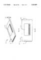
- FIG. 1Ais an isometric view of a ⁇ PDA 10 according to an embodiment of the present invention.
- the unitis modeled on the PCMCIA standard Type II form factor, having a height D1 of about 5 mm.
- Body 12is described in further detail below, and has a female portion 14 of a connector recessed at one end for engaging a mating male portion of the connector in a host computer, connecting the ⁇ PDA internal circuitry directly with a host internal bus.
- the host unitmay be a notebook computer having a docking bay for the ⁇ PDA. Docking bays may be provided in desktop and other types of computers, and even in other kinds of digital equipment, several examples of which are described below.
- a combination I/O interface 16implemented on one side of the ⁇ PDA, comprising a display overlaid with a touch-sensitive planar structure providing softkey operation in conjunction with interactive control routines operable on the ⁇ PDA in a stand-alone mode.
- FIG. 1Athere may also be guides implemented along the sides of the case of the device for guiding the module in and out of a docking bay in a host computer unit. There may also be one or more mechanical features facilitating engagement and disengagement of the module in a docking bay.
- FIG. 1Bis a top plan view of the ⁇ PDA of FIG. 1A, showing a thumbwheel 18 implemented in one corner of the ⁇ PDA.
- the thumbwheel in this embodimentis an input device capable of providing input, with both amplitude and directional characteristics, and in some cases rate characteristics as well.
- the thumbwheelhas many uses in combination with the ⁇ PDA and I/O interface 16. One such use is controlled scrolling of icons, characters, menus, and the like on the display of the device, The thumbwheel provides many of the functions of a pointer device.
- a second external connector portion 20is provided. This connector portion is for engaging peripheral devices as part of an expansion bus interface.
- FIG. 2is a simplified cross-sectional view of a means for constructing a ⁇ PDA according to the present invention in a Type II PCMCIA, or other relatively small package.
- ICs 34are encapsulated in a conformal material 36, and interconnection is accomplished by traces on a flexible polymer film 32 shown as overlaying the encapsulated structure.
- the ICsare not packaged in the conventional manner having solder leads for assembly to a printed circuit board, Rather, connections are made directly between the solder pads on the chip and the traces on the Kapton film.
- ICs indicated by element No. 34with specific functional ICs in a ⁇ PDA. This cross-section is illustrative of a method of construction only.
- LCD display 25is implemented on one side of the ⁇ PDA, and touch-sensitive interface 27 is provided overlaying at least a portion of the LCD display.
- a metal casing 38or other suitable material or combinations of material, surrounds the internal components and conforms to Type II PCMCIA form factors. This simplified cross-section illustrates some of the principles of construction that can allow the needed components to be inexpensively fitted into the small form factor needed.
- the ⁇ PDAis implemented in the form factor of a type III (10 mm thick) PCMCIA unit, using relatively conventional technology, such as PCB technology, rather than the encapsulated construction described immediately above.
- Various other constructions, form factors, and combinationsare possible, as well.
- FIG. 3is a simplified electrical block diagram of the ⁇ PDA of FIGS. 1A, 1B and 2.
- a unique microcontroller 11acts as the CPU of the ⁇ PDA in the stand-alone mode, that is, when the ⁇ PDA is not docked in a host unit.
- microcontroller 11acts as a slave unit, granting bus control to the CPU of the host.
- the CPU of the hostIn docked mode, the CPU of the host thus gains control of the memory contents of the ⁇ PDA, subject in most cases to security procedures which are described below.
- the host computercan transfer data and software into and out of a docked ⁇ PDA memory. In other embodiments many other cooperative operating modes may be accomplished between the two CPUs and accessible memory devices.
- Memory 13is preferably a nonvolatile device from 1 to 2 megabytes in this embodiment, and both control routines for applications and data files are stored in this memory.
- Memory 13may be flash memory, CMOS ROM, CMOS RAM with battery, or a combination, with the software stored in ROM and the data in the flash memory,
- the memory deviceis interfaced to microcontroller 11 via a dedicated bus structure 17, and microprocessor 11 is configured to drive memory bus 17.
- a battery 15is the power source in the stand-alone mode, and may be recharged in one or more of several ways.
- the power tracesare not shown in FIG. 3, but extend to all of the powered devices in the ⁇ PDA module,
- the host power sourcemay be connected to pins through the host interface to recharge the battery,
- an attached meanssuch as a solar panel may be configured to charge the battery and/or provide power to the ⁇ PDA, A solar panel for power is described elsewhere in this disclosure, Also the battery may be easily removed for periodic replacement.
- Host bus connector 14is a part of a host interface which comprises a bus structure 26 for providing connection to the host in docked mode, as described above.
- the host interfaceis according to PCMCIA Type II, Rev. 3 standard, which is capable of communication either in PCMCIA mode or in a mode similar to PCI mode.
- PCI moderefers to a high-speed intermediate bus protocol being developed by Intel corporation, expected to become a standard bus architecture and protocol in the industry.
- the physical interface at the host in this embodimentis a slot-like docking bay, as is typical of know docking bays for PCMCIA devices. This docking bay may be implemented as a docking box, a built-in unit like a floppy-drive unit, or it may take some other form.
- Connector portion 20is a part of the expansion bus interface described above, comprising a dedicated bus structure 40 connected to microcontroller 11.
- This interfacecan be implemented in a number of different ways.
- the purpose of the optional expansion bus interfaceis to connect to optional peripheral devices, such as a printer, a FAX modem, a host cellular phone, and others.
- the expansion bus interfaceis not an essential feature in a minimum embodiment of the present invention, but provides vastly enhanced functionality in many embodiments.
- the expansion interfacecan take any one of several forms.
- a preferred formis an extended enhanced parallel port and protocol based on an invention by the present inventors disclosed in a copending patent application.
- Another formis an indexed I/O port having 8-bit address and 8-bit data capability.
- the requirement of the expansion portis that the connection and communication protocol be compatible with expansion devices, such as telephone modems, fax modems, scanners, and the like. Many other configurations are possible.
- Optional equipmentsuch as devices listed in box 19 may be connected for use with the ⁇ PDA through the expansion bus. Selected ones of such devices may also be built in to the ⁇ PDA in various embodiments, providing variations of applicability. In the former case, connection is through path 21 and the expansion bus interface via connector portion 20. In the built-in case, connection is in the interconnection traces of the ⁇ PDA as indicated by path 23.
- I/O interface 16(also FIG. 1B) is for viewing ⁇ PDA application-related data and for touch-sensitive input via softkeys.
- softkeysis meant assignment by software of various functions to specific touch sensitive screen areas, which act as input keys.
- Labels in I/O interface 16identify functionality of the touch-sensitive areas in various operating modes according to installed machine control routines. LCD display 25 and the touch-sensitive area 27 together form the combination I/O interface 16 described also above.
- data and program securitycomprising an Electrically Erasable Programmable Read Only Memory (EEPROM) 31, which is connected by dedicated communication lines to microcontroller 11.
- EEPROM 31holds one or more codes installed at the point of manufacturing to provide security for information transfer between a host and a ⁇ PDA. The purpose is to control access by a host to the memory contents of a ⁇ PDA, so each ⁇ PDA may be configured to an individual. To accomplish this, clocking and bus mastering machine control routines are initiated at the point of docking, and this security process is described in more detail below.
- security codesmay be provided by a Read Only Memory (ROM) chip or other permanent or semi-permanent memory source.
- FIG. 4is a plan view similar to FIG. 1B, of a ⁇ PDA, showing in particular I/O interface 16.
- I/O interface 16may vary, but in general occupies a major portion of one of the sides of the module.
- I/O interface 16comprises an LCD display with a resolution of 256 by 144 pixels in a screen size that displays 32 by 12 characters. Each character in this embodiment is displayed in an area eight pixels wide and twelve pixels high. In another embodiment, the pixel resolution is 320 by 200, which corresponds to 40 by 16 characters.
- the touch-sensitive areas of the touch-sensitive screencorrespond to the character areas of the display. By touching an area with a finger or stylus, data call be entered quite quickly and with minimal CPU demand.
- thumbwheel 18provides a two-directional means of controlling the configuration of the display according to installed control routines.
- a menu 70is configured at one side to represent the current status of any application in progress and to provide appropriate user menu selections.
- input from thumbwheel 18is used for scrolling through menu 70, and active areas may be indicated by a cursor.
- a usermakes a menu selection by pressing the appropriate touch-sensitive area.
- a specific inputmay be provided to cause the menu area to be displayed on either side of the display according to a user's preference.
- thumbwheel 18may be configured to allow for scrolling and panning.
- a document window 72is provided in this embodiment at the top or bottom of I/O interface 16, A cursor locates the active position within the document for editing purposes.
- Menu 70provides selection of available fonts, and input by thumbwheel 18 controls cursor movement over the document.
- thumbwheel 18As a document will in almost all cases be much larger than the display capability of region 72, it is necessary to pan the document window in essentially the same manner as the keyboard window is panned, For example, rotating thumbwheel 18 in one direction may display horizontal strips of a document, while rotating the thumbwheel in the opposite direction moves the window vertically strips of the same document.
- a soft key or optional hard keymay be configured to switch between the document and keyboard window, and the same or another key may be configured to switch between scrolling left or right, up or down, document or keyboard.
- a switch keymay be used to change the thumbwheel mode of operation.
- a switch keymay also be used in combination with a floating pointer to select characters and menu items. In this embodiment, the user can keep his or her hands relatively stationary on just the thumbwheel and the switch key, making all possible selections, Use of a switch key in combination with a floating pointer facilitates the use of small fonts,
- a switch keymay also be incorporated as an additional hard key in a convenient location on the case 12.
- a further embodiment of the present inventionprovides an I/O set-up application wherein a user may completely customize features of I/O area displays.
- the four-way force-sensitive mouse buttoncan provide menu scrolling of a cursor and panning and/or indexing of keyboard and document windows, while the selector button is used to select and edit according to position of a cursor. This configuration minimizes hand movement and keeps the I/O area clear for viewing.
- thumbwheelsincluding the translation of mechanical motion and pressure to electrical signals and provision of such signals to a microcontroller. For this reason, details of such interfaces are not provided in this disclosure. Combinations of such inputs with displays and input areas may, however, be considered as inventive.
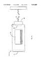
- FIG. 5is an isometric drawing of a ⁇ PDA 10 in position to be docked in a notebook computer 172 via a Type II PCMCIA docking port 105 according to an embodiment of the present invention.
- the ⁇ PDAis activated and a procedure is initiated with the host computer to manage communication and verify memory access rights (security).
- Access rightsare considered important by the inventors for a number of reasons. Firstly, through the expedient of one or more specific codes, unique to each ⁇ PDA, a user may protect files stored in his module from access by unauthorized persons.
- the codecan be used both to control access to data and files via I/O interface 16, and also through the host bus interface, so data and files may be secure from access by an unauthorized host system.
- an application routinecan query the user for an access code to be entered at I/O interface 16 FIG. 4). If the code is not entered properly, access is denied, and power goes off.
- Codes for the purposeare stored in EEPROM 31 (FIG. 3), or in whatever ROM device may be devoted to the purpose. In some embodiments, the code may by mask-programmed at manufacture, so it is not alterable. In others, the code may be accessible and changeable by special procedures in the field.
- a portable or desktop computermay have a docking port physically configured to receive a ⁇ PDA, yet not be configured to communicate with the ⁇ PDA. This certainly might be the case where the ⁇ PDA is in the PCMCIA form.
- this specification terms such a unita generic host. If the unit is configured to communicate with a ⁇ PDA it is an enabled host. If a host is configured for full access to a particular ⁇ PDA, it is a dedicated host.
- a docking unitis a generic host, there will be no communication unless the person presenting the ⁇ PDA provides the control routines to the host. This may be done for a generic host such as by transfer from a floppy disk, from a separate memory card through the docking port, or, in some embodiments, the communication software may be resident in memory 13 (FIG. 3) of a docked ⁇ PDA, transferrable to the host to facilitate further communication.
- the stored code or codes in EEPROM 31may be used to verify authorization for data and program transfer between the host and a ⁇ PDA.
- this procedureis in the following order: First, when one docks a ⁇ PDA in a compatible docking port, certain pin connections convey to both the ⁇ PDA microcontroller and to the host CPU that the module is docked. Assuming an enabled host, the fact of docking commences an initialization protocol on both systems.
- the docking unitis a non-host, that is, it is not capable of communication with the docked module, nothing happens, and the user may simply eject the docked module.
- the computeris an enabled host, an application is started to configure host access to the ⁇ PDA's data files through the ⁇ PDA microcontroller.
- a user interfaceis displayed on the host monitor 104 (FIG. 5).
- the host interface menuas well as other application menus, may be formatted in part as a display of the ⁇ PDA I/O interface 16 as seen in FIG. 4 and described in accompanying text.
- the docked ⁇ PDAcan be operated in situ by manipulating the input areas of the ⁇ PDA displayed on the host's screen.
- a visitor protocolis initiated.
- a visitor menuis displayed on host display 104 for further input, such as password queries for selections of limited data access areas in the docked module.
- a usermay gain full access to the docked module's memory registers by entering the proper password(s).
- full accessmay be immediately granted to the host to access memory contents of the docked module, including program areas; and both data and programs may be exchanged.
- the on-board module microcontrolleragain gains full control of the internal ⁇ PDA bus structures.
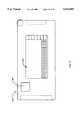
- FIG. 6is a simplified block diagram of a ⁇ PDA docked in a host computer
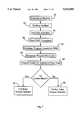
- FIG. 7is a basic logic flow diagram of the steps involved in docking a ⁇ PDA in a host computer 66 according to an embodiment of the present invention.
- Host computer 66is represented in a mostly generic form, having a host CPU 24, and input device 60, such as a keyboard, a mass storage device 28, such as a hard disk drive, and system RAM 62. It will be apparent to those with skill in the art that many hosts may have a much more sophisticated architecture, and the architecture shown is meant to be illustrative.
- connector 14' in FIG. 6comprises portion 14 shown in FIGS. 1B and 3 and a mating connector portion for engaging portion 14 in port 105 (FIG. 5).
- the engagement of the separate portions of the connectorcause bus 26 in the ⁇ PDA and bus 26' in the host to become directly connected. There is then a direct bus path between microcontroller 11 and host CPU 24 (FIG. 6).
- step 42represents insertion of a ⁇ PDA module into the docking port.
- step 44the signalling pin configuration signifies physical docking is accomplished.
- host interface bus 26is activated, including the mated host bus 26' in the host.
- microcontroller 11 in the ⁇ PDAstarts a preprogrammed POST procedure.
- Microcontroller 11 in this embodimenthas a page of RAM 68 implemented on the microcontroller chip. In other embodiments RAM may be used at other locations.
- the POST routineloads a bootstrap program to RAM 68, which includes a code or codes for security matching. This code or codes comprise, for example, a serial number.
- the bootstrap programbegins to execute in microcontroller 11, and at step 56 the microcontroller looks for a password from the host on host interface bus 26 (FIG. 6).
- the fact of dockingassuming an enabled or dedicated host, also causes a communication routine, which may be accessed from, for example, mass storage device 28 at the host, to display a user interface on monitor screen 104 of the host unit, as partly described above. It is this communication program that makes a generic host an enabled host.
- the user interfacewill query a user for input of one or more passwords, after successful entry of which the host will pass the input to microcontroller 11 for comparison with the serial number and perhaps other codes accessed from EEPROM 31 in the bootstrap of the ⁇ PDA.
- microcontroller 11will allow full access to memory 31 at function 52, FIG. 7, for the host CPU, or limited access at some level at function 58, defined by received codes (or no matching code at all).
- the access protocols and procedures allowing partial or direct access to ⁇ PDA memory 13are relatively well known procedures in the art, such as bus mastering techniques, and need not be reproduced in detail here.
- bus mastering techniquesIn addition to simple comparison of codes, there are other techniques that may be incorporated to improve the integrity of security in the communication between a ⁇ PDA and a host.
- executable codemight also be uploaded to onboard RAM 68, or code keys to be used with executable code from other sources, or relatively simple maps re-allocating memory positions and the like, so each ⁇ PDA may be a truly unique device.
- One such featureis automatic updating and cross-referencing of existing files and new files in both computers, under control of the host system, with the host having direct bus access to all memory systems.
- Auto-updatinghas various options, such as auto-updating by clock signature only, flagging new files before transfer, and an editing means that allows the user to review both older and newer versions of files before discarding the older in favor of the newer.
- This automatic or semiautomatic updating of files between the satellite and the hostaddresses a long-standing problem.
- the updating routinesmay also incorporate a backup option to save older files.
- Another useful feature in host/ ⁇ PDA communicationis a means for a user to select and compose a mix of executable program files for downloading to a ⁇ PDA, either replacing or supplementing those executable routines already resident.
- a usercan have several different program lists for downloading as a batch, conveniently configuring the applicability of a ⁇ PDA among a wide variety of expected work environments.
- Such applicationsas databases, spreadsheets, documents, travel files such as currency converters, faxing and other communications programs, time clocks, address and telephone records, and the like, may comprise customized lists of user-preferred applications.
- an undocked ⁇ PDAcan transfer data via the optional expansion bus 40 (FIG. 3) directly to a host.
- a ⁇ PDA userwithout access to a PCMCIA interface on his host (notebook or desk-top) computer, he or she can connect to a host via an auxiliary port on the host, such as a serial port, via the expansion bus interface, In this case, the ⁇ PDA still requests password(s) from the host, and controls access to its on-board memory according to the password(s) received.
- the optional expansion interfacemay also be used in some embodiments while a ⁇ PDA is mastered by a host, wherein the host may effectively send data through the bus structures of the ⁇ PDA.
- a Software Vending Machine with a very large electronic storage capacitywherein a ⁇ PDA user may dock a module and purchase and download software routines compatible with the ⁇ PDA environment.
- FIG. 8is an isometric view of such a vending machine 61 having a docking bay 63 for a ⁇ PDA, a credit card slot 65, and a paper money slot 67.
- a display 69provides a user interface for reviewing and purchasing software from the vending machine, along with selector buttons such as button 71 along the sides of the display.
- the displaymay also have a touch screen, and may, in some embodiments, emulate the ⁇ PDA I/O area on a larger scale.
- a usermay, in this embodiment, review software for sale simply by docking his ⁇ PDA unit in the vending machine and selecting from a menu on display 69.
- the menumay allow the user to browse all available applications, or list new applications since entered dates. The user can select certain applications, try them out, at least in simulation, and then select applications to purchase.
- the vending machineonce all the requirements are met, such as proper identification and payment, copies the selected application(s) to the memory of the ⁇ PDA, or, alternatively, to a floppy disk provided by either the user or the vending machine.
- a floppy disk drive 73in the vending machine and a port 75 for dispensing formatted floppies for a customer to use in the disk drive. This mode is useful for the instances where a user's ⁇ PDA is loaded beyond capacity to receive the desired software, or the user simply wishes to configure the software mix himself from his or her own host computer.
- each user's ⁇ PDAincludes an EEPROM or other storage uniquely identifying the ⁇ PDA by a serial number or other code(s), so the vending machine may be configured in this embodiment to provide the software in one of several modes.
- a usermay buy for a very nominal price a demo copy of an application, which does not provide full capability of the application, but will give the user an opportunity to test and become familiar with an application before purchase.
- the usermay buy a version of the same application, configured to the ID key of the ⁇ PDA to which it is loaded, and operable only on that ⁇ PDA.
- the softwareis transferable between a family of keyed ⁇ PDAs, or has the ability to "unlock" only a limited number of times. In these cases, the applications would be sold at a lesser price than an unlocked version.
- the unlocked versionworks on any ⁇ PDA and/or host/ ⁇ PDA system. The higher price for the unlocked version compensates for the likelihood of unauthorized sharing of the rended applications.
- the vending machinecould also offer a keyed version, customized to operate only on the ⁇ PDA docked in the software vending machine, or upon a family of ⁇ PDAs.
- This keyed versionis possible because of the individual and unique nature of each ⁇ PDA, which has, at a minimum, a unique serial number, and may also have other security programming, as described above, which allows a vending machine to prepare and download a customized copy of an application that will operate only on the particular module for which it is purchased.
- a standard version stored in the memory facility of a vending machinemight be recompiled, for example, on downloading, using a unique code from the docked or identified ⁇ PDA as a key in the compilation, so only the specific ⁇ PDA may run the program by using the same unique key to sequence the instructions while running.
- the key for scrambling or otherwise customizing an applicationmight also comprise other codes and/or executable code sequences stored uniquely in a ⁇ PDA.
- a printer outlet 77which prints a hardcopy manual for the user. It is, of course, not necessary that the software vended be specific to the ⁇ PDA. Applications may also be rended for other kinds of machines, and transported in the memory of the ⁇ PDA, or by floppy disk, etc. In this embodiment a non- ⁇ PDA user can acquire a wide assortment of software.
- the software vending machinemay also serve as an optional informational display center in such locations as airports, train stations, convention centers, and hotels.
- a usermay interface directly and upload current information including, but not limited to, local, national, and world news; stock quotes and financial reports; weather; transportation schedules; road maps; language translators; currency exchange applications; E-mail and other direct on-line services.
- a customized vending machinecould be tailored to business travelers and allow fast access to pertinent information, allowing the user to download files to send via E-mail.
- the vending machinesare linked to each other allowing users to send messages to associates travelling through locations of associated vending machines.
- Such dedicated ⁇ PDA E-mailis immediately downloaded to a specific ⁇ PDA as it is docked.
- the sendermay have the associate's ⁇ PDA unique encoded key as identification, or some other dedicated identifying means for E-mail.
- each business associatemay prompt the custom vending machine in that location via an optional installed infrared interface (not shown) in their ⁇ PDA.
- the custom vending machinealso equipped for infrared communication, receives the signal and sends/or receives any messages that are waiting.
- FIG. 9is a plan view of an enhanced I/O interface unit 79 according to an aspect of the present invention.
- Interface unit 79comprises a combination LCD display at least partially overlaid by a touch-sensitive input screen, providing an I/O area 80 in much the same manner as in a ⁇ PDA.
- Four docking bays 81, 83, 85, and 87are provided in the left and right edges of interface unit 79 in this embodiment, and are configured for PCMCIA type II modules.
- One of these baysmay be used for docking a ⁇ PDA according to the present invention, and the other three to provide a larger CPU, additional memory, battery power, peripheral devices such as modems, and the like by docking functional PCMCIA modules.
- Interface unit 79is a framework for assembling a specialty computer through docking PCMCIA units, including a ⁇ PDA according to the present invention.
- the docking baysmay be configured accordingly.
- a docked ⁇ PDA in this embodimentis configured to produce its I/O display on I/O area 80.
- the thumbwheel on the ⁇ PDAis accessible while docked and acts as described above in the stand-alone mode in this case.
- the enhanced displayhas a re-configured output that enables the user to manipulate the data from the touch-screen alone and/or additional hardware selector buttons and/or a standard keyboard attached to the enhanced display via a dedicated bus port, or even through the expansion port of a docked ⁇ PDA.
- the enhanced displayhas a dedicated mouse port and/or a dedicated thumbwheel.
- interface unit 79has an inexpensive, conventional, replaceable battery and/or a rechargeable battery. Also, in another aspect, interface unit 79 may dock two or more individual ⁇ PDAs and cross-reference data files between them according to control routines that can manipulate mutually unlocked files. Further still, interface unit 79 may be placed and structurally supported for easy viewing on a dedicated standard or smaller-sized keyboard, connecting to the keyboard as an input device. The keyboard would then automatically serve as the input device.
- Interface unit 79 for a ⁇ PDAis small and compact enough to slip into a pocket book or briefcase, providing a very portable, yet very powerful, computer.
- FIG. 10is a plan view of a ⁇ PDA 110 with an I/O interface 116, an expansion port 120, and a host interface connector 114.
- ⁇ PDA 110has all the features previously described and additionally a microphone 88.
- control routines in the ⁇ PDAuse a linear predictive coding (LPC) approach to convert analog input from the microphone to a digital voice recording.
- LPClinear predictive coding
- a two-step integratormay be used in order to separate the analog signal and synthesize a closer digital representation.
- a user's voice notescan be recorded and later uploaded to a host for processing.
- the digital signalsmay be converted to text or sent as voicemail on a network.
- the microphoneis integrated with a speaker for editing purposes.
- FIG. 11is an isometric view of a ⁇ PDA 10 docked in a dedicated cellular telephone 45 according to an embodiment of the present invention.
- Telephone 45has a docking port 49 for a ⁇ PDA according to the invention.
- port 49is on one side of telephone 45, and there is a window 51 to provide access to I/O interface 16 of the ⁇ PDA after it is docked.
- I/O interface 16the software and memory of the ⁇ PDA is available to the telephone and a user may operate the phone by I/O interface 16.
- unique control routines and display configurationsare provided to enhance use of the cellular phone. For example, all of the user's collection of phone numbers, associated credit card numbers, access codes, etc. are readily available and may be quickly and conveniently accessed and used.
- a simple inputdisplays alphabet letters to select, and once a letter is selected, a partial list of parties that might be called is displayed. One may scroll through the list by touch input or by use of the thumbwheel of the ⁇ PDA and select a highlighted entry. It is not required that the telephone numbers be displayed.
- the ⁇ PDAdials the call, including necessary credit card information stored in the memory of the ⁇ PDA for this purpose.
- the callsare timed and time-stamped and a comprehensive log, with areas for notes during and after, is recorded.
- conversationsare digitally recorded and filed for processing later.
- a future embodimentmay include a voice compression program at a host or within cellular phone 45.
- Compressed voice filessuch as, for example, messages to be distributed in a voicemail system, may be downloaded into the ⁇ PDA or carried in a larger memory format inside the cellular telephone.
- the ⁇ PDAcan then send the files via a host or dedicated modem attached at connector portion 20 to the optional expansion bus 40 (FIG. 6).
- the cellular telephonemay, in this particular embodiment, have a bus port for digital transmission.
- the compression algorithmalong with voice system control routines are also established at the receiving end of the transmission to uncompress the signal and distribute individual messages.
- voice messagesmay be sent in a wireless format from the cellular telephone in uncompressed digital synthesized form, distributing them automatically to dedicated receiving hosts, or semi-automatically by manually prompting individual voicemail systems before each individual message.
- a microphone/voicenote ⁇ PDA as in FIG. 10may send previously stored voicenotes after docking in a cellular telephone interface.
- a phone systemIn Europe and Asia a phone system is in use known as CT2, operating on a digital standard and comprising local substations where a party with a compatible cellular phone may access the station simply by being within the active area of the substation,
- a CT2 telephoneis provided with a docking bay for a ⁇ PDA, and configured to work with the ⁇ PDA.
- a compression utilityas disclosed above is provided to digitally compress messages before transmission on the CT2 telephone system,
- control routinesare provided to enable the microphone/voicenote ⁇ PDA as illustrated in FIG. 10 to carry digital voicenotes, either compressed or uncompressed.
- the ⁇ PDA in this embodimentcan transmit the digital voicenotes in compressed form.
- FIG. 12is a plan view of a ⁇ PDA 210 with a microphone/speaker area 90 and a pager interface 92 according to an embodiment of the present invention.
- This ⁇ PDAhas the ability to act as a standard pager, picking up pager signals with installed pager interface 92 and alerting a user through microphone/speaker 90, Once the signals are received, ⁇ PDA 210 can be docked in a compatible cellular telephone as illustrated in FIG. 11 and the ⁇ PDA will automatically dial the caller's telephone number. All other aspects are as described in the docked mode in the cellular telephone.
- the speaker/pager ⁇ PDAcan be prompted to generate DTMF tones.
- the DTMF tonesare generated from a caller's telephone number.
- the speaker/pager ⁇ PDAcan store pager requests in its onboard memory. It can also display all pager requests including time and date stamps, identification of the caller, if known, and other related information, on I/O interface 216.
- a usercan receive a page, respond immediately in digital voicenotes on the ⁇ PDA via speaker/microphone 90, and then send the response from a dedicated ⁇ PDA-compatible cellular telephone or conventional telephone.
- FIG. 13is a plan view of a ⁇ PDA 310 with an IR interface 94 according to an embodiment of the present invention.
- the ⁇ PDAmay communicate with an array of conventional appliances in the home or office for providing remote control.
- Unique signals for the appliancesare programmed into the ⁇ PDA in a learning/receive mode, and filed with user password protection.
- an icon-based menuis displayed on I/O area 316 in a user-friendly format.
- a master routinefirst queries a user for which device to access. For example, in a residential application, icons are displayed for such things as overhead garage doors, security systems, automatic gates, VCRs, television, and stereos.
- a receiving stationsuch as a host computer or peripheral interface has IR capabilities to communicate data directly from a nearby ⁇ PDA with an infrared interface.
- the ⁇ PDAmay interface in a cellular network and act as a wireless modem.
- a ⁇ PDAmay serve as the platform for various peripheral attachments via expansion port 20 (FIG. 1B and others).
- a dedicated pin or pins within expansion port 20signal microcontroller 11, and a peripheral boot-strap application is executed.
- Interfacing control routineswhich may reside in the peripheral or in the memory of the ⁇ PDA, are then executed, and the ⁇ PDA I/O interface displays the related menu-driven options after the linking is complete.
- FIG. 14is a plan view of a ⁇ PDA 10 with a scanner attachment 55 according to an embodiment of the present invention.
- the scanner attachmentis assembled to the ⁇ PDA, making electrical connection via expansion port 20.
- the physical interface of the scanneris shaped to securely attach to the ⁇ PDA.
- Scanner attachment 55has a roller wheel 57 or other translation sensor, which interfaces with wheel 18 of the ⁇ PDA, providing translation sensing in operation for the resulting hand-held scanner.
- scanner attachment 55has a translation device which transmits the proper signal through expansion port 20.
- the scanner oaris on the underside, and one or more batteries 59 are provided within the scanner attachment to provide the extra power needed for light generation.
- scanner attachments 55 of different width D2may be provided for different purposes.
- the barmay be no wider than the ⁇ PDA, or may be eight inches or more in width to scan the full width of U.S. letter size documents, or documents on international A4 paper.
- Unique control routinesdisplay operating information on the ⁇ PDA's I/O area 16 for scanning, providing a user interface for setup of various options, such as the width of the scanner bar, and providing identification for files created in the ⁇ PDA memory as a result of scan passes. Scanned data stored in the ⁇ PDA memory may be quickly transferred to the host via host interface 14 when the ⁇ PDA is docked.
- Unique routinesmay be provided to automate the process, so the user does not have to search for files and initiate all of the transfer processes.
- FIG. 15is a plan view of a ⁇ PDA with a fax-modem module 89 attached according to an embodiment of the present invention.
- a fax and telecommunication capabilityis provided via conventional telephone lines to the ⁇ PDA by fax-modem 89 interfacing to expansion bus interface 20.
- the fax-modemhas internal circuitry for translating from the bus states of the expansion bus to the fax protocol, and a phone plug interface 91.
- the ⁇ PDAcan be docked in a host and be used in combination with fax-modem 89 to provide faxing and file transfers of both host and ⁇ PDA data files. In this case, the fax-modem routines are displayed on the host monitor.
- FIG. 16is a plan view of a ⁇ PDA with a Centronics adapter interface according to an embodiment of the present invention.
- a printer connector 93engages expansion interface 20 by a connector 95 through a cable 97.
- Translation capabilityresides in circuitry in connector 93, which is configured physically as a Centronics connector to engage a standard port on a printer.
- FIG. 17is an isometric view of a ⁇ PDA 10 docked in a barcode reader and acquisition peripheral 100 according to an embodiment of the present invention.
- ⁇ PDA 10is docked in docking bay 149.
- I/O interface 16displays information through opening 147 according to specialized data acquisition applications.
- peripheral 100has an IR interface 94, a microphone 103, a scanner port 101 (not shown), battery pack 105, and a numeric keypad pad 96 implemented as a touch-sensitive array.
- Application routinesenable the data acquisition peripheral to operate as, for example, a mobile inventory management device.
- the usermay scan barcode labels with scanner 101 and enter information, such as counts, on keypad 96 or by voice input via microphone 103. Since applications of peripheral 100 are very specialized, only a limited voice recognition system is needed, The voice recognition system may prompt other command routines within the master applications as well.
- the databasemay be displayed and also manipulated directly via I/O area 16 in open bay 147, or information may be downloaded at a prompt to a nearby host via IR interface 94.
- datamay be stored or an auxiliary option memory location in peripheral 100.
- the data acquisition peripheralmay be interfaced to the analog output of a monitoring device, such as a strip chart recorder, and may digitize and store the incoming analog signals.
- a monitoring devicesuch as a strip chart recorder
- FIG. 18is an isometric view of the side of a ⁇ PDA 10 opposite the I/O interface with a solar charger panel 98 according to an embodiment of the present invention.
- Panel 98is positioned so that when ⁇ PDA 10 is in strong light, such as sunlight, the solar charger absorbs the solar energy and converts it to electricity to recharger battery 15 inside the ⁇ PDA.
- Solar charger 98may be permanently wired to the circuitry of the ⁇ PDA or attached by other means and connected to a dedicated electrical port, or the expansion port. The solar charger is placed so that the ⁇ PDA can be fully docked in a docking port with the panel in place.
- a detachable solar chargermay be unplugged before docking the ⁇ PDA, and the detachable charger may then be of a larger surface area.
- FIG. 19is a largely diagrammatic representation of a Games Center unit 33 according to an aspect of the invention for connecting several ⁇ PDA units (37, 39, 41, and 43) together to allow competitive and interactive games by more than one ⁇ PDA user.
- Games Center unit 33is controlled by an 80486 CPU in this particular embodiment.
- ⁇ PDAsmay be connected to the central unit by cable connection via the expansion bus or the host interface of each ⁇ PDA, through a connector such as connector 35.
- the drawingshows four connectors, but there could be as few as two, and any convenient number greater than two.
- the gaming centermay serve as a conference center where a number of ⁇ PDAs may exchange information.
- a managermay update a number of salespeoples' ⁇ PDAs, including but not limited to merchandise databases, spreadsheets, price sheets, work assignments, customer profiles, address books, telephone books, travel itineraries, and other related business information while in conference.
- FIG. 20is an isometric view of a keyboard 151 connected by a cord and connector 153 to a ⁇ PDA 10 via the expansion port 20.
- the keyboardis a mechanical keyboard having a full-size standard key array and an on-board controller and interface for communicating with the ⁇ PDA.
- the keyboardmay take many other forms, including a two-layer, flexible, roll-up keyboard as taught in U.S. Pat. No. 5,220,521.
- keyboardsIn addition to keyboards, other input devices, such as writing tablets and the like may also be interfaced to a ⁇ PDA via expansion port 20.
- an IR-equipped ⁇ PDA attached to scanner 55may transfer large graphic files in near real time to a host computer. If the files were of text, the host may further process the files automatically through an optical character recognition (OCR) application and send the greatly reduced ASCI files back to the ⁇ PDA.
- OCRoptical character recognition
- the ⁇ PDA family of devicesestablishes a protocol of software security and distribution as well as having the ability to be bus mastered by a host computer system for numerous applications.
- the ⁇ PDA in embodiments of the present inventionhas uses in interfacing with telephone equipment, as is described in detail below, both for purposes of facilitating telephone communication, and for facilitating communication between a ⁇ PDA and other computer equipment over phone lines,
- Dialer devicesare used to generate Dual Tone Multi-Frequency (DTMF) audio signals that are transmitted over telephone lines and used to activate switching equipment to route phone calls
- Small, portable dialer devicesconsist of an electronic tone generator coupled with a circular keying arrangement, They typically have a calculator-type integrated transistor circuitry and are encased with a sensitive microphone in a plastic holder. Such a dialer device replaces the transmitter element in a phone handset.
- DTMFDual Tone Multi-Frequency
- the top of the typical dialerhas a set of push-button, TouchtoneTM key pads which activate DTMF signals that cause automatic dialing of phone numbers, (Touchtone is trademarked by the American Telephone and Telephone Company.) There are twelve key pads corresponding to the digits 0 through 9, the star symbol (*), and the pound symbol (#), Some dialers have four additional keys, designated A, B, C, and D.
- Table 1is a matrix showing the high and low frequency pair, in Hz, required for each of the 16 characters in a full key pad configuration.
- Each character from the touchtone keypadis represented by a dual set of audio frequency signals, which when transmitted together are recognized by other electronic equipment as the unique representation of the keypad character.
- tone dial convertersalso known as tone dial converters
- branch office computersfrom rotary (pulse) lines.
- tone dial converterswere available from many phone outlet and hobby stores. Now that most public phone equipment has been converted to touchtone equipment, the use of these devices is not as common. However, the technology of DTMF tone conversion they perform may have other important applications.
- Coupling one computer to another in a distant locationusually involves some form of modem.
- a modemis circuitry that modulates a carrier wave so digital data can be transmitted over an analog communications line, typically computer-to-computer over a phone line. Modulation alters one or more of the frequency, amplitude, and phase of the carrier wave with respect to time according to a known protocol related to the digital values.
- a receiving modemreconverts (demodulates) the carrier wave to digital data for use by another computer or computerized receiving device.
- modemsare: voice-band--those that are used on voice-grade public phone lines (also known as as dialup modems); acoustic coupler--those that permit a user to dial a phone number, listen for a signal from the other end of the line, and press the telephone receiver into two cushioned cups on the acoustic coupler; and direct connect--those that plug directly into the phone network.
- voice-band--thosethat are used on voice-grade public phone lines (also known as as dialup modems); acoustic coupler--those that permit a user to dial a phone number, listen for a signal from the other end of the line, and press the telephone receiver into two cushioned cups on the acoustic coupler; and direct connect--those that plug directly into the phone network.
- What is needed in these instancesis a means of easily communicating by use of a portable computer, such as a ⁇ PDA according to an embodiment of the present invention, through a phone network without the need to set up a modem and physically secure a phone line connection.
- a portable computersuch as a ⁇ PDA according to an embodiment of the present invention
- the technology of converting DTMF tonesis presently limited to that of the 16 keys on a phone touchtone pad.
- the expansion of DTMF tone conversion to include the entire ASCII code setwould open the door to the transfer of computer code directly through such a portable computer-phone interface.
- FIG. 21is an isometric view of a notebook computer 1011 comprising an embodiment of the present invention.
- the general purpose computer system supporting the embodiment of the dialer inventionis conventional and preferably is in the form of a portable notebook, laptop, or palmtop computer, such as notebook computer 1011, or a ⁇ PDA as in the embodiments described above.
- the enhanced control routines of the inventionprovide a user interface display 1016.
- a usercan specify and select call numbers and other information by using keyboard 1017.
- Some portable computershave a built-in pointer device, such as trackball 1019, which selects menu items and moves a screen cursor on the interface display of the invention, more fully described below.
- the useractivates the dialer applications by input to keyboard 1017.
- the userselects a number to be called and initiates the call from interface display 1016.
- the invention's control routinesrecall the user's credit card information, previously programmed by in memory, and the selected call number.
- the systemtranslates the digital data into the corresponding DTMF signals necessary to dial the number.
- the DTMF signalsare those produced from a standard twelve-button touch-tone telephone key pad.
- the string of DTMF signalsis output in this embodiment through the computer's speaker 13 and are picked up through phone mouthpiece 21, held near the speaker, causing the call to be dialed.
- the computer-driven "dialer”requires no line connection with the phone. The user simply holds the phone handset's mouthpiece near the computer speaker to make the call.
- Thisprovides "on-the-road” portable computer users with a capability to conveniently dial and communicate from phone booths, motel phones, and in other up-to-now impossible situations without the use of a modem. For the traveler the inconvenience of having to set up a modem with electrical connections into a telephone network often will preclude its use, Also most motel rooms and public phones do not have phone jacks.
- the dialer inventiontherefore presents a considerable advantage to the computer user--there is no wiring setup required--and it can be used on any public phone without a phone jack.
- FIG. 21An important feature of the embodiment shown by FIG. 21 is user interface display 1016, which provides a flexible interface to easily operate and edit variable information for the dialer.
- the interfaceis provided in this embodiment through menus as presented in FIGS. 22A, 22B, 22C, 22D, and 22E.
- FIG. 22Ais a screen format for an opening menu in the present embodiment.
- the opening menuis presented when the dialer application is activated from the operating system by user signal.
- the usercan point and select by moving a cursor 1041 with pointer device 1019 or by using the keyboard arrow keys to move the cursor and pressing the ⁇ Enter> or ⁇ Return>) key to make the selection.
- the fieldis activated to accept keyboard input in the manner of an editor or word processor application.
- the mechanisms of these operationsare familiar to those with skill in the art.
- "Manual dial" box 1043can be selected if the user wants to manually enter the number for a call. Entry field 1045 becomes active and displays the number entered. When the correct number is displayed, the user initiates the call by selecting "Click Here to Dial" box 1053.
- Dial List menu 1063(as described below in FIG. 22C) to select a number to be called
- Adjunct items on the opening menuare date 1055, local time 1051, Help option 1057, and Exit option 1059.
- Other user aidsmay be provided in other embodiments as menu items.
- FIGS. 22B through 22Eare shown in FIGS. 22B through 22E.
- FIG. 22Bshows a CALLER INFO menu initiated by selecting 1061 in FIG. 22A, which lets the user specify or change his or her phone credit card information.
- the userselects one of the major carriers, such as "ATT,” “MCI,” or “SPRINT” in line 1069, In other embodiments the carrier list might be expanded.
- the systemresponds by automatically defining the carrier access number, which may be a 1-800 number, to be combined later with other data in dialing. If the user has a carrier other than the ones listed, he/she may select "Other” box 1071 and then enter the carrier access number in box 1072. The user enters his/her call credit card identification on "Credit Card ID" line 1073.
- a Help option 1075is available, The user can abandon the menu and any changes made to its items at any time by selecting Cancel option 1079. The user selects OK option 1077 to save the caller information entered. The specified carrier access number and credit card identification remain in effect unless changed through the CALLER INFO menu in this embodiment of the invention.
- FIG. 22Cshows a DIAL LIST menu activated by selecting 1063 in the menu of FIG. 22A, This menu allows the user to display the list of phone numbers currently stored in computer memory and select a number to be called.
- the listsare accessed in this embodiment by call area code.
- the userfirst enters the desired area code on "Area code:" line 1081.
- area codesare displayed in a scrolling list, and the user may select from the list.
- the usercan display the stored numbers for the selected area code either by phone number or alphabetically by name by selecting Display by Number box 1083 or Display by Name box 1085.
- Names and numbersare displayed in a scrolling list 1082 operated by a conventional scroll bar. Five phone number-name pairs are displayed numerically in order at a time.
- the namecan be that of an individual (last name, first name), company, or a code identifier--whatever the user chooses to identify the party to be called.
- the userscrolls through the list by moving the up/down scroll arrows with pointer device or keyboard. The user then selects the number to dial and the selected number-name pair is highlighted. A Help option 1087 is available.
- OK option 1089is selected.
- the screenmay be exited without altering dial number selection by selecting Cancel option 1091.
- the systemreturns the user to the opening menu (FIG. 22A).
- FIG. 22Dshows an Edit menu activated by selecting 1065 in the opening menu screen shown in FIG. 22A, which allows the user to add, delete, or change phone numbers and names for a specified area code.
- the userfirst types the area code in "Area code:" line 1093.
- the EDIT menuallows the user to display by number or by name by selecting box 1095 or 1097. Five number-name or name-number pairs are displayed in scrolling list 1096.
- Add box 1099To add a new pair, the user selects Add box 1099 and types the number and name in the "Phone number:" and “Name:” fields 1092 and 1094 respectively, and presses ⁇ Enter> or ⁇ Return>. The new number and name appears in order in scrolling list 1096.
- Change box 1101To change a name and/or number, the user selects Change box 1101 and then selects the appropriate pair to be changed from scrolling list 1096. The selected pair will be highlighted and the number and name will appear in fields 1100 and 1102 below the Change box. The user then edits the information in the fields and selects ⁇ Enter> or ⁇ Return>. The change appears in scrolling list 1096. If a mistake is made in entry, the user just selects the number-name pair again and corrects it through the Change option.
- a similar methodis used to delete a number and name pair.
- the userselects Delete box 1105 and then selects the pair to be deleted in scrolling list 1096.
- the systemwill query in a popup window whether the user really wants to delete the pair. The user can select "Yes” or “No.” If "Yes” is selected, the pair will no longer appear in the scrolling list.
- the verification pop-up windowis not shown here.
- a Help option 1107is available on the EDIT menu. Changes to the phone numbers and names can be abandoned at any time by selecting Cancel option 1111. To save all changes, the user selects OK option 1109.
- FIG. 22Eshows a SETUP screen initiated by selecting menu item 1067 in the screen of FIG. 22A, providing a means for the user to define the particular hardware setup he/she will be using in conjunction with the dialer application of the invention.
- the usercan select from three computer-phone configurations.
- Selecting box 1113sets the mode to use the invention's tone dialer with a computer having a built-in speaker.
- Selecting box 1117allows the user to use a conventional modem-phone connection with touch-tone dialing; and selecting box 1119 allows the user to utilize a conventional modem-phone connection with pulse dialing.
- One additional modecomprises a means to send computer-recognizable code to a computer in a remote location.
- Help 1125, OK 1127, and Cancel 1129are available on the SETUP menu.
- An additional embodiment of the inventioncomprises a sound enhancement device 1133 as depicted in FIG. 23A.
- Device 1133is configured to be placed over the computer's built-in speaker 1130.
- a suction cup interface or other convenient unit 1131may be used between the sound enhancement device and the computer so the device makes a snug fit against the computer's speaker.
- FIG. 23Bis a schematic diagram showing the principal components of the sound enhancement device. The sound enhancement device picks up DTMF tones from the computer speaker tones through a microphone 1135, sends the tones through an amplifier circuit 1137, and provides enhanced signals to the device's high-quality output speaker 1139.
- FIG. 24provides an external speaker 1144 to be connected with sound jack 1141 and cable 1143 through the computer's audio output port 1142.
- a sound jack 1146 and cable 1147could connect a computer's audio output port 1145 to a headset attachment 1148 to serve as the speaker.
- a secure fit of the external speaker with the phone mouthpieceis desirable. This can be achieved, as shown in FIG. 26, by adding an interface 1151 to external speaker 1149 so the speaker can be firmly interfaced to phone mouthpiece 1153, thereby mitigating external noise at the interface.
- This additional featureis desirable when using phones in busy, high noise environments such as airports, conference rooms, or phone booths on a busy street.
- control routinesprovide a unique means for sending code in DTMF tones from a portable computer and telephone interface 1157 as described above, over phone lines 1148 to a computer 1161 in a remote location, as shown in FIG. 27.
- the remote unit in this embodimenthas decoding ability to accept the DTMF tone-based data from a phone line and translate it into a digital representation interpretable as American Standard Code for Information Interchange (ASCII) computer code.
- FIG. 28provides a matrix that shows the DTMF tone values assigned to each character in the ASCII set.
- a decoderis implemented in the remote unit in this embodiment for receiving input DTMF data.
- the decodercan be implemented by an add-on card connected to the computer bus and to the phone line by a phone jack 1159.
- the userselects box 1121 in the screen of FIG. 22E, and the system then displays a selection screen shown in FIG. 29.
- the selection screenhas a scrolling list 1163 of formats for data transfer, each unique to a particular purpose. Such formats may be furnished with dialer applications in this embodiment, or, in alternative embodiments, an editor may be provided for creating new applications.
- An example of a data transfer formatis message format 1165 in the scrolling list of FIG. 29.
- the userselects the format, which is then highlighted in the scrolling list, and then selects "OK" box 1166.
- the systemdisplays the message format screen shown in FIG. 30.
- the systemprovides the user with an active scrolling entry field 1167, wherein text may be entered in the manner of a text editor or word processor.
- a checkbox 1173for activating an entry field 1177 to enter a recipient ID or destination for the massage, which may be decoded and used at the receiving end to direct the message to a specific recipient.
- selecting "OK" box 1169displays opening menu shown in FIG. 22A. The user simply selects the number and dials as in other embodiments. When the number is dialed and the connection made, if the "Remote Unit" selection is active in the screen shown in FIG. 22E, the system will transfer the text by DTMF code according to the table of FIG. 28.
- the remote unithave a receiving modem to decode the incoming DTMF tones and provide the resulting data on the receiving computer's bus.
- the modemhas a receiver capable of interpreting two simultaneous DTMF tones, a processor for managing operations, and a look-up table according to FIG. 28, as well as control routines for directing the CPU in managing the modem.
Landscapes
- Engineering & Computer Science (AREA)
- Theoretical Computer Science (AREA)
- General Engineering & Computer Science (AREA)
- Computer Hardware Design (AREA)
- Physics & Mathematics (AREA)
- General Physics & Mathematics (AREA)
- Signal Processing (AREA)
- Human Computer Interaction (AREA)
- Multimedia (AREA)
- Computing Systems (AREA)
- Computer Networks & Wireless Communication (AREA)
- Computer Security & Cryptography (AREA)
- Software Systems (AREA)
- Health & Medical Sciences (AREA)
- General Health & Medical Sciences (AREA)
- Power Engineering (AREA)
- Acoustics & Sound (AREA)
- Microelectronics & Electronic Packaging (AREA)
- Bioethics (AREA)
- Audiology, Speech & Language Pathology (AREA)
- Mathematical Physics (AREA)
- Calculators And Similar Devices (AREA)
- Mobile Radio Communication Systems (AREA)
- Telephonic Communication Services (AREA)
Abstract
Description
TABLE 1 ______________________________________ Lower Frequency Higher Frequency (Hz) (Hz) 1209 1336 1447 1633 ______________________________________ 697 1 2 3 A 770 4 5 6 B 852 7 8 9 C 941 * 0 # D ______________________________________
Claims (5)
Priority Applications (4)
| Application Number | Priority Date | Filing Date | Title |
|---|---|---|---|
| US08/304,266US5522089A (en) | 1993-05-07 | 1994-09-12 | Personal digital assistant module adapted for initiating telephone communications through DTMF dialing |
| EP95933183AEP0781429A4 (en) | 1994-09-12 | 1995-09-11 | PERSONAL DIGITAL MICROASSISTANT |
| PCT/US1995/012027WO1996008759A1 (en) | 1994-09-12 | 1995-09-11 | Micro personal digital assistant |
| JP8510413AJPH10508397A (en) | 1994-09-12 | 1995-09-11 | Ultra-compact personal portable information devices |
Applications Claiming Priority (3)
| Application Number | Priority Date | Filing Date | Title |
|---|---|---|---|
| US5892293A | 1993-05-07 | 1993-05-07 | |
| US08/144,231US5835732A (en) | 1993-10-28 | 1993-10-28 | Miniature digital assistant having enhanced host communication |
| US08/304,266US5522089A (en) | 1993-05-07 | 1994-09-12 | Personal digital assistant module adapted for initiating telephone communications through DTMF dialing |
Related Parent Applications (2)
| Application Number | Title | Priority Date | Filing Date |
|---|---|---|---|
| US5892293AContinuation-In-Part | 1993-05-07 | 1993-05-07 | |
| US08/144,231Continuation-In-PartUS5835732A (en) | 1992-06-29 | 1993-10-28 | Miniature digital assistant having enhanced host communication |
Publications (1)
| Publication Number | Publication Date |
|---|---|
| US5522089Atrue US5522089A (en) | 1996-05-28 |
Family
ID=23175775
Family Applications (1)
| Application Number | Title | Priority Date | Filing Date |
|---|---|---|---|
| US08/304,266Expired - LifetimeUS5522089A (en) | 1993-05-07 | 1994-09-12 | Personal digital assistant module adapted for initiating telephone communications through DTMF dialing |
Country Status (4)
| Country | Link |
|---|---|
| US (1) | US5522089A (en) |
| EP (1) | EP0781429A4 (en) |
| JP (1) | JPH10508397A (en) |
| WO (1) | WO1996008759A1 (en) |
Cited By (165)
| Publication number | Priority date | Publication date | Assignee | Title |
|---|---|---|---|---|
| WO1996027950A1 (en)* | 1995-03-07 | 1996-09-12 | Geotek Communications, Inc. | A subscriber unit for use in a multiple access communication system |
| US5619396A (en)* | 1995-02-21 | 1997-04-08 | Intel Corporation | Modular PCMCIA card |
| US5627974A (en)* | 1993-11-12 | 1997-05-06 | Texas Instruments Incorporated | Computer docking system with means for allowing a microprocessor in a docking station to talk to a central processing unit in a docked portable computer |
| US5640566A (en)* | 1994-08-01 | 1997-06-17 | Apple Computer, Inc. | Method of forming an editor |
| US5664228A (en)* | 1995-08-09 | 1997-09-02 | Microsoft Corporation | Portable information device and system and method for downloading executable instructions from a computer to the portable information device |
| US5684873A (en)* | 1995-01-09 | 1997-11-04 | Nokia Mobile Phones Limited | Quick dialing in personal mobile phone |
| WO1997050222A1 (en)* | 1996-06-27 | 1997-12-31 | Mci Communications Corporation | Wireless smart phone |
| US5710810A (en)* | 1995-01-05 | 1998-01-20 | Nokia Mobile Phones Limited | Quick dialing in a mobile phone |
| WO1998009250A1 (en)* | 1996-08-26 | 1998-03-05 | KÜHN, Günter, Ernstné | Card telephone apparatus with telephone card for publicity purposes |
| US5745733A (en)* | 1995-08-09 | 1998-04-28 | Ncr Corporation | Computer system including a portable portion and a stationary portion providing both uni-processing and multiprocessing capabilities |
| US5748512A (en)* | 1995-02-28 | 1998-05-05 | Microsoft Corporation | Adjusting keyboard |
| US5790897A (en)* | 1995-08-21 | 1998-08-04 | New Media Corp. | Plug-in computer card with internal audio speaker element |
| US5797089A (en)* | 1995-09-07 | 1998-08-18 | Telefonaktiebolaget Lm Ericsson (Publ) | Personal communications terminal having switches which independently energize a mobile telephone and a personal digital assistant |
| US5848298A (en)* | 1995-02-21 | 1998-12-08 | Intel Corporation | System having two PC cards in a hinged carrying case with battery compartment within in the hinge section |
| US5854828A (en)* | 1996-08-20 | 1998-12-29 | Dell U.S.A., L.P. | Telephone customer support utility |
| US5875307A (en)* | 1995-06-05 | 1999-02-23 | National Semiconductor Corporation | Method and apparatus to enable docking/undocking of a powered-on bus to a docking station |
| US5892971A (en)* | 1986-08-08 | 1999-04-06 | Norand Corporation | Portable data processing device having an indicia reader and a multi-tasking operating system capable of executing battery monitoring instructions while concurrently executing application programs |
| US5892975A (en)* | 1995-05-31 | 1999-04-06 | Intel Corporation | System for wake-up module on PC card detecting switches had actuated and causing image to display to appear that was displayed when turned off |
| US5896575A (en)* | 1997-02-28 | 1999-04-20 | Motorola, Inc. | Electronic device with display viewable from two opposite ends |
| US5903631A (en)* | 1997-03-12 | 1999-05-11 | Mitel Corporation | One-button intelligent CTI dialler |
| US5907815A (en)* | 1995-12-07 | 1999-05-25 | Texas Instruments Incorporated | Portable computer stored removable mobile telephone |
| WO1999037074A1 (en)* | 1997-01-15 | 1999-07-22 | Siemens Aktiengesellschaft | Storage device for a communications terminal |
| US5978654A (en)* | 1995-01-03 | 1999-11-02 | Ultratec, Inc. | Alphanumeric paging entry system |
| US5986568A (en)* | 1995-09-29 | 1999-11-16 | Kabushiki Kaisha Toshiba | Information transfer method, information transfer system, information inputting method, information input device, and system for supporting various operations |
| US6097375A (en)* | 1996-12-13 | 2000-08-01 | International Business Machines Corporation | System, method, and pointing device for remote operation of data processing apparatus |
| US6124826A (en)* | 1994-10-07 | 2000-09-26 | Mannesmann Aktiengesellschaft | Navigation device for people |
| US6134454A (en)* | 1995-12-18 | 2000-10-17 | At&T Corp. | System and method for maintaining personal communications information in a mobile communications system |
| US6141711A (en)* | 1996-12-19 | 2000-10-31 | National Semiconductor Corporation | Method and apparatus to enable insertion/ejection of a device in a computer system while maintaining operation of the computer system and application software |
| US6163274A (en)* | 1997-09-04 | 2000-12-19 | Ncr Corporation | Remotely updatable PDA |
| US6173041B1 (en) | 1997-11-13 | 2001-01-09 | Advanced Micro Devices, Inc. | System and method for reducing call interruptions on a telephone |
| US6178230B1 (en)* | 1997-11-13 | 2001-01-23 | Advanced Micro Devices, Inc. | System and method for identifying a callee of an incoming telephone call |
| WO2001023983A1 (en)* | 1999-09-30 | 2001-04-05 | Xiring | Device comprising a computer and a peripheral for remote communication by sound link |
| US6247074B1 (en) | 1997-10-02 | 2001-06-12 | Samsung Electronics Co., Ltd. | Portable computer with telephone line switching function and an expansion system and method for use therewith |
| US6259769B1 (en) | 1999-05-04 | 2001-07-10 | Cubic Corporation | Portable smart card communication device |
| US6266236B1 (en) | 1997-08-27 | 2001-07-24 | Vadem | Apparatus and method for connecting and articulating display in a portable computer having multiple display orientations |
| US6272545B1 (en) | 1997-10-24 | 2001-08-07 | Microsoft Corporation | System and method for interaction between one or more desktop computers and one or more mobile devices |
| US6275230B1 (en)* | 1997-08-22 | 2001-08-14 | Ncr Corporation | Method for managing states within activex controls simplifying CTI enabled application development |
| US20010021659A1 (en)* | 2000-03-08 | 2001-09-13 | Nec Corporation | Method and system for connecting a mobile communication unit to a personal computer |
| WO2001080530A1 (en)* | 2000-04-14 | 2001-10-25 | Walker James H | Telephonic transaction system |
| US20010034245A1 (en)* | 2000-02-01 | 2001-10-25 | Swartz Allen I. | Portable telephone interface for a laptop computer |
| US20020035581A1 (en)* | 2000-06-06 | 2002-03-21 | Microsoft Corporation | Application program interfaces for semantically labeling strings and providing actions based on semantically labeled strings |
| US6366787B1 (en)* | 1998-06-11 | 2002-04-02 | Sharp Kabushiki Kaisha | Cellular telephone |
| US6374245B1 (en)* | 1997-04-10 | 2002-04-16 | Samsung Electronics Co., Ltd. | Server system communicating with personal digital assistant and communication method thereof |
| US6373925B1 (en) | 1996-06-28 | 2002-04-16 | Siemens Aktiengesellschaft | Telephone calling party announcement system and method |
| US6385303B1 (en) | 1997-11-13 | 2002-05-07 | Legerity, Inc. | System and method for identifying and announcing a caller and a callee of an incoming telephone call |
| US6385202B1 (en)* | 1997-10-01 | 2002-05-07 | At&T Corp. | Method and system for allowing access to traditional voice mail and interactive voice response systems over internet-like networks |
| US20020060698A1 (en)* | 2000-09-18 | 2002-05-23 | Salla Laurikka | Method for forming an information element, and an electronic device |
| US6396921B1 (en) | 1997-11-07 | 2002-05-28 | Nortel Networks Limited | Method and system for encoding and decoding typographic characters |
| US6411503B1 (en) | 1996-10-11 | 2002-06-25 | Fujitsu Limited | Portable type information apparatus |
| US20020087591A1 (en)* | 2000-06-06 | 2002-07-04 | Microsoft Corporation | Method and system for providing restricted actions for recognized semantic categories |
| US6434403B1 (en) | 1999-02-19 | 2002-08-13 | Bodycom, Inc. | Personal digital assistant with wireless telephone |
| USD463424S1 (en) | 1999-02-19 | 2002-09-24 | Bodycom, Inc. | Personal digital assistant with wireless telephone |
| US20020169608A1 (en)* | 1999-10-04 | 2002-11-14 | Comsense Technologies Ltd. | Sonic/ultrasonic authentication device |
| US20020181442A1 (en)* | 2001-05-29 | 2002-12-05 | Purshotam Rajani | Multimode personal communication system and method |
| US20020186823A1 (en)* | 1996-08-13 | 2002-12-12 | Dan Kikinis | Electronic document answering machine |
| US6496979B1 (en) | 1997-10-24 | 2002-12-17 | Microsoft Corporation | System and method for managing application installation for a mobile device |
| US6505055B1 (en) | 1997-08-04 | 2003-01-07 | Starfish Software, Inc. | Camel-back digital organizer and communication protocol for a cellular phone device |
| US6523079B2 (en) | 1993-02-19 | 2003-02-18 | Elonex Ip Holdings Ltd | Micropersonal digital assistant |
| US6539358B1 (en)* | 2000-05-24 | 2003-03-25 | Delphi Technologies, Inc. | Voice-interactive docking station for a portable computing device |
| US20030078978A1 (en)* | 2001-10-23 | 2003-04-24 | Clifford Lardin | Firmware portable messaging units utilizing proximate communications |
| US6560100B1 (en) | 1996-10-24 | 2003-05-06 | Fujitsu Limited | Portable computer equipped with add-on battery |
| US20030125959A1 (en)* | 2001-12-31 | 2003-07-03 | Palmquist Robert D. | Translation device with planar microphone array |
| US6614547B1 (en)* | 1997-08-08 | 2003-09-02 | Samsung Electronics Co., Ltd. | Cordless facsimile system with telephone answering function and method for controlling the same |
| US6618578B1 (en) | 1997-02-14 | 2003-09-09 | Statsignal Systems, Inc | System and method for communicating with a remote communication unit via the public switched telephone network (PSTN) |
| US20030199288A1 (en)* | 1998-05-01 | 2003-10-23 | Starfish Software, Inc. | Enhanced companion digital organizer for a cellular phone device |
| US20030220795A1 (en)* | 2002-05-23 | 2003-11-27 | Microsoft Corporation | Method, system, and apparatus for converting currency values based upon semantically lableled strings |
| US6658268B1 (en) | 1998-05-01 | 2003-12-02 | Motorola, Inc. | Enhanced companion digital organizer for a cellular phone device |
| US6690949B1 (en)* | 1999-09-30 | 2004-02-10 | Skyworks Solutions, Inc. | System and process for supporting multiple wireless standards with a single circuit architecture |
| US20040031856A1 (en)* | 1998-09-16 | 2004-02-19 | Alon Atsmon | Physical presence digital authentication system |
| US6728812B1 (en)* | 1997-06-16 | 2004-04-27 | Citizen Watch Co., Ltd. | Portable information terminal |
| EP0932287A3 (en)* | 1998-01-26 | 2004-05-12 | Sharp Kabushiki Kaisha | Personal digital assistance device |
| US20040090473A1 (en)* | 2002-11-08 | 2004-05-13 | Bryan Scott | Performance enhancement and upgrade attachment for a handheld computer |
| US20040137938A1 (en)* | 2002-12-20 | 2004-07-15 | Deubler Donald L. | Method and system for emergency dialing of a wireless communication device |
| US20040162833A1 (en)* | 2003-02-13 | 2004-08-19 | Microsoft Corporation | Linking elements of a document to corresponding fields, queries and/or procedures in a database |
| US20040217992A1 (en)* | 2003-05-01 | 2004-11-04 | Oskulak Ray M | Tablet accessory for personal electronics devices |
| US20040217937A1 (en)* | 2003-05-01 | 2004-11-04 | Ray Moskalik | Distributed PDA processing and method for computational operating continuity |
| US20040230666A1 (en)* | 2003-05-14 | 2004-11-18 | Microsoft Corporation | Method, system, and computer-readable medium for communicating results to a data query in a computer network |
| US20040253945A1 (en)* | 1999-03-04 | 2004-12-16 | Janik Craig M. | System for providing content, management, and interactivity for thin client devices |
| US20040268237A1 (en)* | 2003-06-27 | 2004-12-30 | Microsoft Corporation | Leveraging markup language data for semantically labeling text strings and data and for providing actions based on semantically labeled text strings and data |
| EP1393457A4 (en)* | 2001-05-07 | 2005-01-05 | John F King | Modem function and usage of a personal digital assistant in wireless mode |
| US20050020305A1 (en)* | 1993-10-13 | 2005-01-27 | Callaghan Francis John | Data entry systems |
| US20050060123A1 (en)* | 1993-11-12 | 2005-03-17 | Entek Ird International Corporation | Portable, self-contained data collection systems and methods |
| US20050108195A1 (en)* | 2002-05-07 | 2005-05-19 | Microsoft Corporation | Method, system, and apparatus for processing information based on the discovery of semantically labeled strings |
| US6915332B1 (en)* | 1998-04-08 | 2005-07-05 | Opentv, Inc. | System and method for one touch e-mail reply |
| US20050182617A1 (en)* | 2004-02-17 | 2005-08-18 | Microsoft Corporation | Methods and systems for providing automated actions on recognized text strings in a computer-generated document |
| US20050210101A1 (en)* | 1999-03-04 | 2005-09-22 | Universal Electronics Inc. | System and method for providing content, management, and interactivity for client devices |
| US20050226394A1 (en)* | 2004-02-18 | 2005-10-13 | Engelke Robert M | Captioned telephone service |
| US6976217B1 (en)* | 2000-10-13 | 2005-12-13 | Palmsource, Inc. | Method and apparatus for integrating phone and PDA user interface on a single processor |
| US6982702B1 (en)* | 1998-06-12 | 2006-01-03 | Hewlett-Packard Development Company, L.P. | Portable computer system |
| US20060003770A1 (en)* | 2004-06-14 | 2006-01-05 | Seyong Park | Virtual phone service over wireless systems |
| US20060080471A1 (en)* | 2004-10-13 | 2006-04-13 | Microsoft Corporation | Offline caching of control transactions for storage devices |
| US20060080359A1 (en)* | 2004-10-13 | 2006-04-13 | Microsoft Corporation | Electronic labeling for offline management of storage devices |
| US20060149813A1 (en)* | 1999-03-04 | 2006-07-06 | Simple Devices | System and method for providing content, management, and interactivity for client devices |
| US7079810B2 (en) | 1997-02-14 | 2006-07-18 | Statsignal Ipc, Llc | System and method for communicating with a remote communication unit via the public switched telephone network (PSTN) |
| US7085591B2 (en) | 2001-01-27 | 2006-08-01 | Mitel Networks Corporation | PDA enabled telephone |
| US7103511B2 (en) | 1998-10-14 | 2006-09-05 | Statsignal Ipc, Llc | Wireless communication networks for providing remote monitoring of devices |
| US7123212B2 (en)* | 2000-12-22 | 2006-10-17 | Harman International Industries, Inc. | Information transmission and display method and system for a handheld computing device |
| US7137550B1 (en) | 1997-02-14 | 2006-11-21 | Statsignal Ipc, Llc | Transmitter for accessing automated financial transaction machines |
| US20060271646A1 (en)* | 1995-05-25 | 2006-11-30 | Janky James M | Enhanced delivery of audio data for portable playback |
| US20070006146A1 (en)* | 2005-06-24 | 2007-01-04 | Kwong Wah Y | Systems and apparatus for enhanced mobile computing platforms |
| US20070036282A1 (en)* | 2005-06-29 | 2007-02-15 | Ultratec, Inc. | Device independent text captioned telephone service |
| US20070103431A1 (en)* | 2005-10-24 | 2007-05-10 | Tabatowski-Bush Benjamin A | Handheld tilt-text computing system and method |
| US7263073B2 (en) | 1999-03-18 | 2007-08-28 | Statsignal Ipc, Llc | Systems and methods for enabling a mobile user to notify an automated monitoring system of an emergency situation |
| US20070223182A1 (en)* | 2006-03-23 | 2007-09-27 | Solution Technologies, Inc. | Modular protective housing with peripherals for a handheld communicatons device |
| US7295128B2 (en) | 1998-06-22 | 2007-11-13 | Sipco, Llc | Smoke detection methods, devices, and systems |
| US20080021886A1 (en)* | 2005-09-26 | 2008-01-24 | Microsoft Corporation | Lingtweight reference user interface |
| US7334735B1 (en)* | 1998-10-02 | 2008-02-26 | Beepcard Ltd. | Card for interaction with a computer |
| US7397907B2 (en) | 1997-02-14 | 2008-07-08 | Sipco, Llc | Multi-function general purpose transceiver |
| US20080166984A1 (en)* | 2007-01-09 | 2008-07-10 | Terrence John Shie | Multiband or multimode receiver with shared bias circuit |
| US20080187108A1 (en)* | 2005-06-29 | 2008-08-07 | Engelke Robert M | Device Independent Text Captioned Telephone Service |
| US20080215240A1 (en)* | 2006-12-18 | 2008-09-04 | Damian Howard | Integrating User Interfaces |
| US7424527B2 (en) | 2001-10-30 | 2008-09-09 | Sipco, Llc | System and method for transmitting pollution information over an integrated wireless network |
| US7451195B1 (en)* | 1998-11-16 | 2008-11-11 | Lucent Technologies Inc. | Method and system for operating a PDA for use with an IP phone device |
| US7480501B2 (en) | 2001-10-24 | 2009-01-20 | Statsignal Ipc, Llc | System and method for transmitting an emergency message over an integrated wireless network |
| US7480692B2 (en) | 1998-10-02 | 2009-01-20 | Beepcard Inc. | Computer communications using acoustic signals |
| US20090077203A1 (en)* | 1999-03-04 | 2009-03-19 | Ez4Media, Inc. | Clock with link to the internet |
| US20090088257A1 (en)* | 1994-12-19 | 2009-04-02 | Legal Igaming, Inc. | System and method for connecting gaming devices to a network for remote play |
| US7650425B2 (en) | 1999-03-18 | 2010-01-19 | Sipco, Llc | System and method for controlling communication between a host computer and communication devices associated with remote devices in an automated monitoring system |
| US7653687B2 (en) | 1994-05-31 | 2010-01-26 | Reisman Richard R | Method for distributing content to a user station |
| US7697492B2 (en) | 1998-06-22 | 2010-04-13 | Sipco, Llc | Systems and methods for monitoring and controlling remote devices |
| US7707496B1 (en) | 2002-05-09 | 2010-04-27 | Microsoft Corporation | Method, system, and apparatus for converting dates between calendars and languages based upon semantically labeled strings |
| US7711550B1 (en) | 2003-04-29 | 2010-05-04 | Microsoft Corporation | Methods and system for recognizing names in a computer-generated document and for providing helpful actions associated with recognized names |
| US7716676B2 (en) | 2002-06-25 | 2010-05-11 | Microsoft Corporation | System and method for issuing a message to a program |
| US7716163B2 (en) | 2000-06-06 | 2010-05-11 | Microsoft Corporation | Method and system for defining semantic categories and actions |
| US7742048B1 (en) | 2002-05-23 | 2010-06-22 | Microsoft Corporation | Method, system, and apparatus for converting numbers based upon semantically labeled strings |
| US7756086B2 (en) | 2004-03-03 | 2010-07-13 | Sipco, Llc | Method for communicating in dual-modes |
| US7770102B1 (en) | 2000-06-06 | 2010-08-03 | Microsoft Corporation | Method and system for semantically labeling strings and providing actions based on semantically labeled strings |
| US7778816B2 (en) | 2001-04-24 | 2010-08-17 | Microsoft Corporation | Method and system for applying input mode bias |
| US7788590B2 (en) | 2005-09-26 | 2010-08-31 | Microsoft Corporation | Lightweight reference user interface |
| US7805542B2 (en) | 1997-02-25 | 2010-09-28 | George W. Hindman | Mobile unit attached in a mobile environment that fully restricts access to data received via wireless signal to a separate computer in the mobile environment |
| US20100250789A1 (en)* | 2009-03-27 | 2010-09-30 | Qualcomm Incorporated | System and method of managing memory at a portable computing device and a portable computing device docking station |
| US20100251361A1 (en)* | 2009-03-27 | 2010-09-30 | Qualcomm Incorporated | System and method of managing security between a portable computing device and a portable computing device docking station |
| US20100250816A1 (en)* | 2009-03-27 | 2010-09-30 | Qualcomm Incorporated | System and method of managing displays at a portable computing device and a portable computing device docking station |
| US20100250817A1 (en)* | 2009-03-27 | 2010-09-30 | Qualcomm Incorporated | System and method of managing data communication at a portable computing device and a portable computing device docking station |
| US20100251243A1 (en)* | 2009-03-27 | 2010-09-30 | Qualcomm Incorporated | System and method of managing the execution of applications at a portable computing device and a portable computing device docking station |
| US7827546B1 (en) | 2002-06-05 | 2010-11-02 | Microsoft Corporation | Mechanism for downloading software components from a remote source for use by a local software application |
| US20110014947A1 (en)* | 2008-12-29 | 2011-01-20 | Hui-Hu Liang | System and Method for Transferring the Operation of an Image Device to an External Apparatus |
| US20110170672A1 (en)* | 2010-01-13 | 2011-07-14 | Engelke Robert M | Captioned telephone service |
| US8000314B2 (en) | 1996-12-06 | 2011-08-16 | Ipco, Llc | Wireless network system and method for providing same |
| US8013732B2 (en) | 1998-06-22 | 2011-09-06 | Sipco, Llc | Systems and methods for monitoring and controlling remote devices |
| US8019609B2 (en) | 1999-10-04 | 2011-09-13 | Dialware Inc. | Sonic/ultrasonic authentication method |
| US8031650B2 (en) | 2004-03-03 | 2011-10-04 | Sipco, Llc | System and method for monitoring remote devices with a dual-mode wireless communication protocol |
| US20110265156A1 (en)* | 2008-12-24 | 2011-10-27 | Gemalto Sa | Portable security device protection against keystroke loggers |
| US8064412B2 (en) | 1998-06-22 | 2011-11-22 | Sipco, Llc | Systems and methods for monitoring conditions |
| US8410931B2 (en) | 1998-06-22 | 2013-04-02 | Sipco, Llc | Mobile inventory unit monitoring systems and methods |
| US8489063B2 (en) | 2001-10-24 | 2013-07-16 | Sipco, Llc | Systems and methods for providing emergency messages to a mobile device |
| US8620938B2 (en) | 2002-06-28 | 2013-12-31 | Microsoft Corporation | Method, system, and apparatus for routing a query to one or more providers |
| US20140018175A1 (en)* | 1996-11-14 | 2014-01-16 | Bally Gaming, Inc. | Wireless gaming network |
| US8706708B2 (en) | 2002-06-06 | 2014-04-22 | Microsoft Corporation | Providing contextually sensitive tools and help content in computer-generated documents |
| US8787246B2 (en) | 2009-02-03 | 2014-07-22 | Ipco, Llc | Systems and methods for facilitating wireless network communication, satellite-based wireless network systems, and aircraft-based wireless network systems, and related methods |
| US8908838B2 (en) | 2001-08-23 | 2014-12-09 | Ultratec, Inc. | System for text assisted telephony |
| US9152196B2 (en) | 2009-03-27 | 2015-10-06 | Qualcomm Incorporated | System and method of managing power at a portable computing device and a portable computing device docking station |
| US9219708B2 (en) | 2001-03-22 | 2015-12-22 | DialwareInc. | Method and system for remotely authenticating identification devices |
| US9251649B2 (en) | 2002-10-09 | 2016-02-02 | Zynga Inc. | System and method for connecting gaming devices to a network for remote play |
| US20160057336A1 (en)* | 2000-07-26 | 2016-02-25 | Kdl Scan Designs Llc | Method and system for hosting entity-specific photo-sharing websites for entity-specific digital cameras |
| US9439126B2 (en) | 2005-01-25 | 2016-09-06 | Sipco, Llc | Wireless network protocol system and methods |
| US10389876B2 (en) | 2014-02-28 | 2019-08-20 | Ultratec, Inc. | Semiautomated relay method and apparatus |
| US10748523B2 (en) | 2014-02-28 | 2020-08-18 | Ultratec, Inc. | Semiautomated relay method and apparatus |
| US10878721B2 (en) | 2014-02-28 | 2020-12-29 | Ultratec, Inc. | Semiautomated relay method and apparatus |
| US10917519B2 (en) | 2014-02-28 | 2021-02-09 | Ultratec, Inc. | Semiautomated relay method and apparatus |
| US11030607B2 (en)* | 2011-12-19 | 2021-06-08 | Paypal, Inc. | System and method for facilitating electronic financial transactions during a phone call |
| US11258900B2 (en) | 2005-06-29 | 2022-02-22 | Ultratec, Inc. | Device independent text captioned telephone service |
| US11539900B2 (en) | 2020-02-21 | 2022-12-27 | Ultratec, Inc. | Caption modification and augmentation systems and methods for use by hearing assisted user |
| US11664029B2 (en) | 2014-02-28 | 2023-05-30 | Ultratec, Inc. | Semiautomated relay method and apparatus |
| US20230353551A1 (en)* | 2019-09-18 | 2023-11-02 | Bioconnect Inc. | Access control system |
Families Citing this family (6)
| Publication number | Priority date | Publication date | Assignee | Title |
|---|---|---|---|---|
| DE19724927A1 (en)* | 1997-06-12 | 1998-12-17 | Jean Denis Rochat | Device for processing data |
| FR2767434B1 (en)* | 1997-08-12 | 2002-02-08 | Gilles Maton | LOCALIZABLE MULTI-APPLICATION ACTIVE TERMINAL FOR READING IDENTIFIED PROGRAMS IN A PUNCTUAL LINK WITH A PERSONALIZED MANAGEMENT AND PROCESSING CENTER |
| BE1012308A3 (en)* | 1998-11-25 | 2000-09-05 | Minds Naamloze Vennootschap | Personal digital assistant device |
| US8707061B2 (en) | 2009-03-27 | 2014-04-22 | Qualcomm Incorporated | System and method of providing scalable computing between a portable computing device and a portable computing device docking station |
| US8630088B2 (en) | 2009-03-27 | 2014-01-14 | Qualcomm Incorporated | Portable docking station for a portable computing device |
| EP4557513A3 (en)* | 2013-05-15 | 2025-07-30 | TactoTek Oy | Enabling arrangement for an electronic device with housing-integrated functionalities and method therefor |
Citations (22)
| Publication number | Priority date | Publication date | Assignee | Title |
|---|---|---|---|---|
| US4016542A (en)* | 1974-04-23 | 1977-04-05 | Azurdata, Inc. | Electronic notebook for use in data gathering, formatting and transmitting system |
| US4534012A (en)* | 1980-07-16 | 1985-08-06 | Kabushiki Kaisha Suwa Seikosha | Portable programmable information device and external programming station |
| US4545023A (en)* | 1980-11-14 | 1985-10-01 | Engineering Project Development Limited | Hand-held computer |
| US4748656A (en)* | 1986-03-21 | 1988-05-31 | American Telephone And Telegraph Company | Personal computer--as an interface between a telephone station set and a business communication system |
| US4763356A (en)* | 1986-12-11 | 1988-08-09 | AT&T Information Systems, Inc. American Telephone and Telegraph Company | Touch screen form entry system |
| US4849674A (en)* | 1987-03-12 | 1989-07-18 | The Cherry Corporation | Electroluminescent display with interlayer for improved forming |
| US5029183A (en)* | 1989-06-29 | 1991-07-02 | Symbol Technologies, Inc. | Packet data communication network |
| US5133076A (en)* | 1989-06-12 | 1992-07-21 | Grid Systems Corporation | Hand held computer |
| US5164982A (en)* | 1990-09-27 | 1992-11-17 | Radish Communications Systems, Inc. | Telecommunication display system |
| US5195130A (en)* | 1988-05-05 | 1993-03-16 | Transaction Technology, Inc. | Computer and telephone apparatus with user friendly computer interface and enhanced integrity features |
| US5210854A (en)* | 1989-06-14 | 1993-05-11 | Digital Equipment Corporation | System for updating program stored in eeprom by storing new version into new location and updating second transfer vector to contain starting address of new version |
| US5231571A (en)* | 1990-08-14 | 1993-07-27 | Personal Financial Assistant, Inc. | Personal financial assistant computer method |
| US5283862A (en)* | 1989-10-11 | 1994-02-01 | Lund Alan K | Notebook computer with reversible cover for external use of membrane switch screen |
| US5324925A (en)* | 1992-09-25 | 1994-06-28 | Norand Corporation | Hand-held data terminal and communicator |
| US5335276A (en)* | 1992-12-16 | 1994-08-02 | Texas Instruments Incorporated | Communication system and methods for enhanced information transfer |
| US5365577A (en)* | 1990-09-27 | 1994-11-15 | Radish Communications Systems, Inc. | Telecommunication display system |
| US5375076A (en)* | 1993-09-10 | 1994-12-20 | Compaq Computer Corporation | Combined notepad and notebook computer |
| US5379057A (en)* | 1988-11-14 | 1995-01-03 | Microslate, Inc. | Portable computer with touch screen and computer system employing same |
| US5408382A (en)* | 1992-01-10 | 1995-04-18 | Norand Corporation | Terminal and docking mechanism with open channel members and guide rollers |
| US5465401A (en)* | 1992-12-15 | 1995-11-07 | Texas Instruments Incorporated | Communication system and methods for enhanced information transfer |
| US5468947A (en)* | 1986-08-08 | 1995-11-21 | Norand Corporation | Pocket size data capture unit with processor and shell modules |
| US5483581A (en)* | 1989-01-23 | 1996-01-09 | Intellicall, Inc. | Method and apparatus for performing an automated collect call |
Family Cites Families (2)
| Publication number | Priority date | Publication date | Assignee | Title |
|---|---|---|---|---|
| US4837811A (en)* | 1988-01-25 | 1989-06-06 | Communication Manufacturing Co. | Telephone technician's terminals |
| WO1994003865A1 (en)* | 1992-08-06 | 1994-02-17 | Abelow, Daniel, H. | Customer-based product design module |
- 1994
- 1994-09-12USUS08/304,266patent/US5522089A/ennot_activeExpired - Lifetime
- 1995
- 1995-09-11EPEP95933183Apatent/EP0781429A4/ennot_activeWithdrawn
- 1995-09-11WOPCT/US1995/012027patent/WO1996008759A1/ennot_activeApplication Discontinuation
- 1995-09-11JPJP8510413Apatent/JPH10508397A/enactivePending
Patent Citations (22)
| Publication number | Priority date | Publication date | Assignee | Title |
|---|---|---|---|---|
| US4016542A (en)* | 1974-04-23 | 1977-04-05 | Azurdata, Inc. | Electronic notebook for use in data gathering, formatting and transmitting system |
| US4534012A (en)* | 1980-07-16 | 1985-08-06 | Kabushiki Kaisha Suwa Seikosha | Portable programmable information device and external programming station |
| US4545023A (en)* | 1980-11-14 | 1985-10-01 | Engineering Project Development Limited | Hand-held computer |
| US4748656A (en)* | 1986-03-21 | 1988-05-31 | American Telephone And Telegraph Company | Personal computer--as an interface between a telephone station set and a business communication system |
| US5468947A (en)* | 1986-08-08 | 1995-11-21 | Norand Corporation | Pocket size data capture unit with processor and shell modules |
| US4763356A (en)* | 1986-12-11 | 1988-08-09 | AT&T Information Systems, Inc. American Telephone and Telegraph Company | Touch screen form entry system |
| US4849674A (en)* | 1987-03-12 | 1989-07-18 | The Cherry Corporation | Electroluminescent display with interlayer for improved forming |
| US5195130A (en)* | 1988-05-05 | 1993-03-16 | Transaction Technology, Inc. | Computer and telephone apparatus with user friendly computer interface and enhanced integrity features |
| US5379057A (en)* | 1988-11-14 | 1995-01-03 | Microslate, Inc. | Portable computer with touch screen and computer system employing same |
| US5483581A (en)* | 1989-01-23 | 1996-01-09 | Intellicall, Inc. | Method and apparatus for performing an automated collect call |
| US5133076A (en)* | 1989-06-12 | 1992-07-21 | Grid Systems Corporation | Hand held computer |
| US5210854A (en)* | 1989-06-14 | 1993-05-11 | Digital Equipment Corporation | System for updating program stored in eeprom by storing new version into new location and updating second transfer vector to contain starting address of new version |
| US5029183A (en)* | 1989-06-29 | 1991-07-02 | Symbol Technologies, Inc. | Packet data communication network |
| US5283862A (en)* | 1989-10-11 | 1994-02-01 | Lund Alan K | Notebook computer with reversible cover for external use of membrane switch screen |
| US5231571A (en)* | 1990-08-14 | 1993-07-27 | Personal Financial Assistant, Inc. | Personal financial assistant computer method |
| US5365577A (en)* | 1990-09-27 | 1994-11-15 | Radish Communications Systems, Inc. | Telecommunication display system |
| US5164982A (en)* | 1990-09-27 | 1992-11-17 | Radish Communications Systems, Inc. | Telecommunication display system |
| US5408382A (en)* | 1992-01-10 | 1995-04-18 | Norand Corporation | Terminal and docking mechanism with open channel members and guide rollers |
| US5324925A (en)* | 1992-09-25 | 1994-06-28 | Norand Corporation | Hand-held data terminal and communicator |
| US5465401A (en)* | 1992-12-15 | 1995-11-07 | Texas Instruments Incorporated | Communication system and methods for enhanced information transfer |
| US5335276A (en)* | 1992-12-16 | 1994-08-02 | Texas Instruments Incorporated | Communication system and methods for enhanced information transfer |
| US5375076A (en)* | 1993-09-10 | 1994-12-20 | Compaq Computer Corporation | Combined notepad and notebook computer |
Cited By (304)
| Publication number | Priority date | Publication date | Assignee | Title |
|---|---|---|---|---|
| US5892971A (en)* | 1986-08-08 | 1999-04-06 | Norand Corporation | Portable data processing device having an indicia reader and a multi-tasking operating system capable of executing battery monitoring instructions while concurrently executing application programs |
| US20050041385A1 (en)* | 1993-02-19 | 2005-02-24 | Dan Kikinis | Micro personal digital assistant with a compressed BIOS system |
| US6523079B2 (en) | 1993-02-19 | 2003-02-18 | Elonex Ip Holdings Ltd | Micropersonal digital assistant |
| US20090247225A2 (en)* | 1993-10-13 | 2009-10-01 | Dataquill Limited | Data Entry Systems |
| US7505785B2 (en) | 1993-10-13 | 2009-03-17 | Dataquill Limited | Data entry systems |
| US7139591B2 (en) | 1993-10-13 | 2006-11-21 | Dataquill Limited | Hand held telecommunications and data entry device |
| US20090111521A1 (en)* | 1993-10-13 | 2009-04-30 | Dataquill Limited | Data Entry Systems |
| US20050020305A1 (en)* | 1993-10-13 | 2005-01-27 | Callaghan Francis John | Data entry systems |
| US7920898B2 (en) | 1993-10-13 | 2011-04-05 | Dataquill Limited | Data entry systems |
| US8290538B2 (en) | 1993-10-13 | 2012-10-16 | Dataquill Limited | Data entry systems |
| US5627974A (en)* | 1993-11-12 | 1997-05-06 | Texas Instruments Incorporated | Computer docking system with means for allowing a microprocessor in a docking station to talk to a central processing unit in a docked portable computer |
| US6341320B1 (en)* | 1993-11-12 | 2002-01-22 | Texas Instruments Incorporated | Computer docking station with PCMCIA card slot |
| US20050060123A1 (en)* | 1993-11-12 | 2005-03-17 | Entek Ird International Corporation | Portable, self-contained data collection systems and methods |
| US9484077B2 (en) | 1994-05-31 | 2016-11-01 | Intellectual Ventures I Llc | Providing services from a remote computer system to a user station over a communications network |
| US9111604B2 (en) | 1994-05-31 | 2015-08-18 | Intellectual Ventures I Llc | Software and method that enables selection of on-line content from one of a plurality of network content service providers in a single action |
| US8719339B2 (en) | 1994-05-31 | 2014-05-06 | Intellectual Ventures I Llc | Software and method that enables selection of one of a plurality of online service providers |
| US8069204B2 (en) | 1994-05-31 | 2011-11-29 | Twintech E.U., Limited Liability Company | Providing and receiving content over a wireless communication system |
| US8812620B2 (en) | 1994-05-31 | 2014-08-19 | Intellectual Property I LLC | Software and method that enables selection of one of a plurality of online service providers |
| US8825872B2 (en) | 1994-05-31 | 2014-09-02 | Intellectual Ventures I Llc | Software and method for monitoring a data stream and for capturing desired data within the data stream |
| US8321499B2 (en) | 1994-05-31 | 2012-11-27 | Intellectual Ventures I Llc | Method for distributing content to a user station |
| US8407682B2 (en) | 1994-05-31 | 2013-03-26 | Intellectual Ventures I Llc | Software and method that enables selection of one of a plurality of online service providers |
| US8024399B2 (en) | 1994-05-31 | 2011-09-20 | Twintech E.U., Limited Liability Company | Software distribution over a network |
| US9484078B2 (en) | 1994-05-31 | 2016-11-01 | Intellectual Ventures I Llc | Providing services from a remote computer system to a user station over a communications network |
| US8635272B2 (en) | 1994-05-31 | 2014-01-21 | Intellectual Ventures I Llc | Method for distributing a list of updated content to a user station from a distribution server wherein the user station may defer installing the update |
| US8499030B1 (en)* | 1994-05-31 | 2013-07-30 | Intellectual Ventures I Llc | Software and method that enables selection of one of a plurality of network communications service providers |
| US7653687B2 (en) | 1994-05-31 | 2010-01-26 | Reisman Richard R | Method for distributing content to a user station |
| US8131883B1 (en) | 1994-05-31 | 2012-03-06 | Intellectual Ventures I, Limited Liability Company | Method for distributing content to a user station |
| US5640566A (en)* | 1994-08-01 | 1997-06-17 | Apple Computer, Inc. | Method of forming an editor |
| US6124826A (en)* | 1994-10-07 | 2000-09-26 | Mannesmann Aktiengesellschaft | Navigation device for people |
| US8959154B2 (en)* | 1994-12-19 | 2015-02-17 | Zynga Inc. | System and method for connecting gaming devices to a network for remote play |
| US20090088257A1 (en)* | 1994-12-19 | 2009-04-02 | Legal Igaming, Inc. | System and method for connecting gaming devices to a network for remote play |
| US5978654A (en)* | 1995-01-03 | 1999-11-02 | Ultratec, Inc. | Alphanumeric paging entry system |
| US5710810A (en)* | 1995-01-05 | 1998-01-20 | Nokia Mobile Phones Limited | Quick dialing in a mobile phone |
| US5684873A (en)* | 1995-01-09 | 1997-11-04 | Nokia Mobile Phones Limited | Quick dialing in personal mobile phone |
| US5848298A (en)* | 1995-02-21 | 1998-12-08 | Intel Corporation | System having two PC cards in a hinged carrying case with battery compartment within in the hinge section |
| US5619396A (en)* | 1995-02-21 | 1997-04-08 | Intel Corporation | Modular PCMCIA card |
| US5748512A (en)* | 1995-02-28 | 1998-05-05 | Microsoft Corporation | Adjusting keyboard |
| WO1996027950A1 (en)* | 1995-03-07 | 1996-09-12 | Geotek Communications, Inc. | A subscriber unit for use in a multiple access communication system |
| US20060271646A1 (en)* | 1995-05-25 | 2006-11-30 | Janky James M | Enhanced delivery of audio data for portable playback |
| US8423626B2 (en) | 1995-05-25 | 2013-04-16 | Mobilemedia Ideas Llc | Enhanced delivery of audio data for portable playback |
| US20090077204A1 (en)* | 1995-05-25 | 2009-03-19 | Sony Corporation | Enhanced delivery of audio data for portable playback |
| US5892975A (en)* | 1995-05-31 | 1999-04-06 | Intel Corporation | System for wake-up module on PC card detecting switches had actuated and causing image to display to appear that was displayed when turned off |
| US5875307A (en)* | 1995-06-05 | 1999-02-23 | National Semiconductor Corporation | Method and apparatus to enable docking/undocking of a powered-on bus to a docking station |
| US5878282A (en)* | 1995-08-09 | 1999-03-02 | Microsoft Corporation | Portable information device and system and method for downloading executable instruction from a computer to the portable information device |
| US5664228A (en)* | 1995-08-09 | 1997-09-02 | Microsoft Corporation | Portable information device and system and method for downloading executable instructions from a computer to the portable information device |
| US5745733A (en)* | 1995-08-09 | 1998-04-28 | Ncr Corporation | Computer system including a portable portion and a stationary portion providing both uni-processing and multiprocessing capabilities |
| US5790897A (en)* | 1995-08-21 | 1998-08-04 | New Media Corp. | Plug-in computer card with internal audio speaker element |
| US5797089A (en)* | 1995-09-07 | 1998-08-18 | Telefonaktiebolaget Lm Ericsson (Publ) | Personal communications terminal having switches which independently energize a mobile telephone and a personal digital assistant |
| US5986568A (en)* | 1995-09-29 | 1999-11-16 | Kabushiki Kaisha Toshiba | Information transfer method, information transfer system, information inputting method, information input device, and system for supporting various operations |
| US5907815A (en)* | 1995-12-07 | 1999-05-25 | Texas Instruments Incorporated | Portable computer stored removable mobile telephone |
| US6134454A (en)* | 1995-12-18 | 2000-10-17 | At&T Corp. | System and method for maintaining personal communications information in a mobile communications system |
| WO1997050222A1 (en)* | 1996-06-27 | 1997-12-31 | Mci Communications Corporation | Wireless smart phone |
| US6373925B1 (en) | 1996-06-28 | 2002-04-16 | Siemens Aktiengesellschaft | Telephone calling party announcement system and method |
| US6973167B2 (en)* | 1996-08-13 | 2005-12-06 | Lextron System, Inc. | Electronic document answering machine |
| US8666044B2 (en) | 1996-08-13 | 2014-03-04 | Yuzalla Investments Llc | Electronic document answering machine |
| US20040091087A1 (en)* | 1996-08-13 | 2004-05-13 | Dan Kikinis | Electronic document answering machine |
| US20020186823A1 (en)* | 1996-08-13 | 2002-12-12 | Dan Kikinis | Electronic document answering machine |
| US5854828A (en)* | 1996-08-20 | 1998-12-29 | Dell U.S.A., L.P. | Telephone customer support utility |
| WO1998009250A1 (en)* | 1996-08-26 | 1998-03-05 | KÜHN, Günter, Ernstné | Card telephone apparatus with telephone card for publicity purposes |
| US6804113B2 (en) | 1996-10-11 | 2004-10-12 | Fujitsu Limited | Portable-type information apparatus |
| US6948966B2 (en) | 1996-10-11 | 2005-09-27 | Fujitsu Limited | Portable-type information apparatus |
| US6411503B1 (en) | 1996-10-11 | 2002-06-25 | Fujitsu Limited | Portable type information apparatus |
| US6724615B2 (en) | 1996-10-11 | 2004-04-20 | Fujitsu Limited | Portable-type information apparatus |
| US6674637B2 (en) | 1996-10-24 | 2004-01-06 | Fujitsu Limited | Portable computer equipped with add-on battery |
| US20060034047A1 (en)* | 1996-10-24 | 2006-02-16 | Fujitsu Limited | Portable computer equipped with add-on battery |
| US6560100B1 (en) | 1996-10-24 | 2003-05-06 | Fujitsu Limited | Portable computer equipped with add-on battery |
| US7199999B2 (en) | 1996-10-24 | 2007-04-03 | Fujitsu Limited | Portable computer equipped with add-on battery |
| US6956734B2 (en) | 1996-10-24 | 2005-10-18 | Fujitsu Limited | Portable computer equipped with add-on battery |
| US6563702B1 (en) | 1996-10-24 | 2003-05-13 | Fujitsu Limited | Portable computer equipped with add-on battery |
| US20140018175A1 (en)* | 1996-11-14 | 2014-01-16 | Bally Gaming, Inc. | Wireless gaming network |
| US8000314B2 (en) | 1996-12-06 | 2011-08-16 | Ipco, Llc | Wireless network system and method for providing same |
| US8625496B2 (en) | 1996-12-06 | 2014-01-07 | Ipco, Llc | Wireless network system and method for providing same |
| US8233471B2 (en) | 1996-12-06 | 2012-07-31 | Ipco, Llc | Wireless network system and method for providing same |
| US8982856B2 (en) | 1996-12-06 | 2015-03-17 | Ipco, Llc | Systems and methods for facilitating wireless network communication, satellite-based wireless network systems, and aircraft-based wireless network systems, and related methods |
| US6097375A (en)* | 1996-12-13 | 2000-08-01 | International Business Machines Corporation | System, method, and pointing device for remote operation of data processing apparatus |
| US6141711A (en)* | 1996-12-19 | 2000-10-31 | National Semiconductor Corporation | Method and apparatus to enable insertion/ejection of a device in a computer system while maintaining operation of the computer system and application software |
| WO1999037074A1 (en)* | 1997-01-15 | 1999-07-22 | Siemens Aktiengesellschaft | Storage device for a communications terminal |
| US6618578B1 (en) | 1997-02-14 | 2003-09-09 | Statsignal Systems, Inc | System and method for communicating with a remote communication unit via the public switched telephone network (PSTN) |
| US7079810B2 (en) | 1997-02-14 | 2006-07-18 | Statsignal Ipc, Llc | System and method for communicating with a remote communication unit via the public switched telephone network (PSTN) |
| US7397907B2 (en) | 1997-02-14 | 2008-07-08 | Sipco, Llc | Multi-function general purpose transceiver |
| US7137550B1 (en) | 1997-02-14 | 2006-11-21 | Statsignal Ipc, Llc | Transmitter for accessing automated financial transaction machines |
| US7805542B2 (en) | 1997-02-25 | 2010-09-28 | George W. Hindman | Mobile unit attached in a mobile environment that fully restricts access to data received via wireless signal to a separate computer in the mobile environment |
| US5896575A (en)* | 1997-02-28 | 1999-04-20 | Motorola, Inc. | Electronic device with display viewable from two opposite ends |
| US5903631A (en)* | 1997-03-12 | 1999-05-11 | Mitel Corporation | One-button intelligent CTI dialler |
| US6374245B1 (en)* | 1997-04-10 | 2002-04-16 | Samsung Electronics Co., Ltd. | Server system communicating with personal digital assistant and communication method thereof |
| US6728812B1 (en)* | 1997-06-16 | 2004-04-27 | Citizen Watch Co., Ltd. | Portable information terminal |
| US6505055B1 (en) | 1997-08-04 | 2003-01-07 | Starfish Software, Inc. | Camel-back digital organizer and communication protocol for a cellular phone device |
| US6614547B1 (en)* | 1997-08-08 | 2003-09-02 | Samsung Electronics Co., Ltd. | Cordless facsimile system with telephone answering function and method for controlling the same |
| US6275230B1 (en)* | 1997-08-22 | 2001-08-14 | Ncr Corporation | Method for managing states within activex controls simplifying CTI enabled application development |
| US6266236B1 (en) | 1997-08-27 | 2001-07-24 | Vadem | Apparatus and method for connecting and articulating display in a portable computer having multiple display orientations |
| US6163274A (en)* | 1997-09-04 | 2000-12-19 | Ncr Corporation | Remotely updatable PDA |
| US6385202B1 (en)* | 1997-10-01 | 2002-05-07 | At&T Corp. | Method and system for allowing access to traditional voice mail and interactive voice response systems over internet-like networks |
| US6247074B1 (en) | 1997-10-02 | 2001-06-12 | Samsung Electronics Co., Ltd. | Portable computer with telephone line switching function and an expansion system and method for use therewith |
| US6496979B1 (en) | 1997-10-24 | 2002-12-17 | Microsoft Corporation | System and method for managing application installation for a mobile device |
| US6272545B1 (en) | 1997-10-24 | 2001-08-07 | Microsoft Corporation | System and method for interaction between one or more desktop computers and one or more mobile devices |
| US6396921B1 (en) | 1997-11-07 | 2002-05-28 | Nortel Networks Limited | Method and system for encoding and decoding typographic characters |
| US6704395B1 (en) | 1997-11-13 | 2004-03-09 | Legerity, Inc. | System and method for reducing call interruptions on a telephone |
| US6385303B1 (en) | 1997-11-13 | 2002-05-07 | Legerity, Inc. | System and method for identifying and announcing a caller and a callee of an incoming telephone call |
| US6711239B1 (en) | 1997-11-13 | 2004-03-23 | Legerity, Inc. | System and method for identifying a callee of an incoming telephone call |
| US6178230B1 (en)* | 1997-11-13 | 2001-01-23 | Advanced Micro Devices, Inc. | System and method for identifying a callee of an incoming telephone call |
| US6173041B1 (en) | 1997-11-13 | 2001-01-09 | Advanced Micro Devices, Inc. | System and method for reducing call interruptions on a telephone |
| EP0932287A3 (en)* | 1998-01-26 | 2004-05-12 | Sharp Kabushiki Kaisha | Personal digital assistance device |
| US6915332B1 (en)* | 1998-04-08 | 2005-07-05 | Opentv, Inc. | System and method for one touch e-mail reply |
| US20030199288A1 (en)* | 1998-05-01 | 2003-10-23 | Starfish Software, Inc. | Enhanced companion digital organizer for a cellular phone device |
| US6658268B1 (en) | 1998-05-01 | 2003-12-02 | Motorola, Inc. | Enhanced companion digital organizer for a cellular phone device |
| US7072688B2 (en) | 1998-05-01 | 2006-07-04 | Motorola, Inc. | Enhanced companion digital organizer for a cellular phone device |
| US6366787B1 (en)* | 1998-06-11 | 2002-04-02 | Sharp Kabushiki Kaisha | Cellular telephone |
| US6982702B1 (en)* | 1998-06-12 | 2006-01-03 | Hewlett-Packard Development Company, L.P. | Portable computer system |
| US9691263B2 (en) | 1998-06-22 | 2017-06-27 | Sipco, Llc | Systems and methods for monitoring conditions |
| US7697492B2 (en) | 1998-06-22 | 2010-04-13 | Sipco, Llc | Systems and methods for monitoring and controlling remote devices |
| US9571582B2 (en) | 1998-06-22 | 2017-02-14 | Sipco, Llc | Systems and methods for monitoring and controlling remote devices |
| US8212667B2 (en) | 1998-06-22 | 2012-07-03 | Sipco, Llc | Automotive diagnostic data monitoring systems and methods |
| US8064412B2 (en) | 1998-06-22 | 2011-11-22 | Sipco, Llc | Systems and methods for monitoring conditions |
| US8223010B2 (en) | 1998-06-22 | 2012-07-17 | Sipco Llc | Systems and methods for monitoring vehicle parking |
| US8964708B2 (en) | 1998-06-22 | 2015-02-24 | Sipco Llc | Systems and methods for monitoring and controlling remote devices |
| US8410931B2 (en) | 1998-06-22 | 2013-04-02 | Sipco, Llc | Mobile inventory unit monitoring systems and methods |
| US9430936B2 (en) | 1998-06-22 | 2016-08-30 | Sipco Llc | Systems and methods for monitoring and controlling remote devices |
| US7295128B2 (en) | 1998-06-22 | 2007-11-13 | Sipco, Llc | Smoke detection methods, devices, and systems |
| US9129497B2 (en) | 1998-06-22 | 2015-09-08 | Statsignal Systems, Inc. | Systems and methods for monitoring conditions |
| US8013732B2 (en) | 1998-06-22 | 2011-09-06 | Sipco, Llc | Systems and methods for monitoring and controlling remote devices |
| US8078136B2 (en) | 1998-09-16 | 2011-12-13 | Dialware Inc. | Physical presence digital authentication system |
| US8062090B2 (en) | 1998-09-16 | 2011-11-22 | Dialware Inc. | Interactive toys |
| US9830778B2 (en) | 1998-09-16 | 2017-11-28 | Dialware Communications, Llc | Interactive toys |
| US20040031856A1 (en)* | 1998-09-16 | 2004-02-19 | Alon Atsmon | Physical presence digital authentication system |
| US8425273B2 (en) | 1998-09-16 | 2013-04-23 | Dialware Inc. | Interactive toys |
| US8509680B2 (en) | 1998-09-16 | 2013-08-13 | Dialware Inc. | Physical presence digital authentication system |
| US8843057B2 (en) | 1998-09-16 | 2014-09-23 | Dialware Inc. | Physical presence digital authentication system |
| US20090264205A1 (en)* | 1998-09-16 | 2009-10-22 | Beepcard Ltd. | Interactive toys |
| US9275517B2 (en) | 1998-09-16 | 2016-03-01 | Dialware Inc. | Interactive toys |
| US7706838B2 (en) | 1998-09-16 | 2010-04-27 | Beepcard Ltd. | Physical presence digital authentication system |
| US9607475B2 (en) | 1998-09-16 | 2017-03-28 | Dialware Inc | Interactive toys |
| US7568963B1 (en) | 1998-09-16 | 2009-08-04 | Beepcard Ltd. | Interactive toys |
| US7480692B2 (en) | 1998-10-02 | 2009-01-20 | Beepcard Inc. | Computer communications using acoustic signals |
| US8935367B2 (en) | 1998-10-02 | 2015-01-13 | Dialware Inc. | Electronic device and method of configuring thereof |
| US7334735B1 (en)* | 1998-10-02 | 2008-02-26 | Beepcard Ltd. | Card for interaction with a computer |
| US20090067291A1 (en)* | 1998-10-02 | 2009-03-12 | Beepcard Inc. | Computer communications using acoustic signals |
| US8544753B2 (en) | 1998-10-02 | 2013-10-01 | Dialware Inc. | Card for interaction with a computer |
| US9361444B2 (en) | 1998-10-02 | 2016-06-07 | Dialware Inc. | Card for interaction with a computer |
| US7941480B2 (en) | 1998-10-02 | 2011-05-10 | Beepcard Inc. | Computer communications using acoustic signals |
| US7103511B2 (en) | 1998-10-14 | 2006-09-05 | Statsignal Ipc, Llc | Wireless communication networks for providing remote monitoring of devices |
| US7451195B1 (en)* | 1998-11-16 | 2008-11-11 | Lucent Technologies Inc. | Method and system for operating a PDA for use with an IP phone device |
| USD463424S1 (en) | 1999-02-19 | 2002-09-24 | Bodycom, Inc. | Personal digital assistant with wireless telephone |
| US6434403B1 (en) | 1999-02-19 | 2002-08-13 | Bodycom, Inc. | Personal digital assistant with wireless telephone |
| US20090077203A1 (en)* | 1999-03-04 | 2009-03-19 | Ez4Media, Inc. | Clock with link to the internet |
| US9042205B2 (en) | 1999-03-04 | 2015-05-26 | Viviana Research Llc | Clock with link to the internet |
| US20050210101A1 (en)* | 1999-03-04 | 2005-09-22 | Universal Electronics Inc. | System and method for providing content, management, and interactivity for client devices |
| US7937450B2 (en) | 1999-03-04 | 2011-05-03 | Viviana Research Llc | System for providing content, management, and interactivity for thin client devices |
| US20040253945A1 (en)* | 1999-03-04 | 2004-12-16 | Janik Craig M. | System for providing content, management, and interactivity for thin client devices |
| US20090298490A9 (en)* | 1999-03-04 | 2009-12-03 | Janik Craig M | System for providing content, management, and interactivity for thin client devices |
| US20060149813A1 (en)* | 1999-03-04 | 2006-07-06 | Simple Devices | System and method for providing content, management, and interactivity for client devices |
| US8930571B2 (en) | 1999-03-18 | 2015-01-06 | Sipco, LLP | Systems and methods for controlling communication between a host computer and communication devices |
| US8924588B2 (en) | 1999-03-18 | 2014-12-30 | Sipco, Llc | Systems and methods for controlling communication between a host computer and communication devices |
| US7650425B2 (en) | 1999-03-18 | 2010-01-19 | Sipco, Llc | System and method for controlling communication between a host computer and communication devices associated with remote devices in an automated monitoring system |
| US8924587B2 (en) | 1999-03-18 | 2014-12-30 | Sipco, Llc | Systems and methods for controlling communication between a host computer and communication devices |
| US7263073B2 (en) | 1999-03-18 | 2007-08-28 | Statsignal Ipc, Llc | Systems and methods for enabling a mobile user to notify an automated monitoring system of an emergency situation |
| US6259769B1 (en) | 1999-05-04 | 2001-07-10 | Cubic Corporation | Portable smart card communication device |
| FR2799330A1 (en)* | 1999-09-30 | 2001-04-06 | Xiring | DEVICE COMPRISING A COMPUTER AND A DEVICE COMMUNICATING REMOTELY BY SOUND CONNECTION |
| WO2001023983A1 (en)* | 1999-09-30 | 2001-04-05 | Xiring | Device comprising a computer and a peripheral for remote communication by sound link |
| US6690949B1 (en)* | 1999-09-30 | 2004-02-10 | Skyworks Solutions, Inc. | System and process for supporting multiple wireless standards with a single circuit architecture |
| US8447615B2 (en) | 1999-10-04 | 2013-05-21 | Dialware Inc. | System and method for identifying and/or authenticating a source of received electronic data by digital signal processing and/or voice authentication |
| US7280970B2 (en) | 1999-10-04 | 2007-10-09 | Beepcard Ltd. | Sonic/ultrasonic authentication device |
| US9489949B2 (en) | 1999-10-04 | 2016-11-08 | Dialware Inc. | System and method for identifying and/or authenticating a source of received electronic data by digital signal processing and/or voice authentication |
| US20020169608A1 (en)* | 1999-10-04 | 2002-11-14 | Comsense Technologies Ltd. | Sonic/ultrasonic authentication device |
| US8019609B2 (en) | 1999-10-04 | 2011-09-13 | Dialware Inc. | Sonic/ultrasonic authentication method |
| US20040220807A9 (en)* | 1999-10-04 | 2004-11-04 | Comsense Technologies Ltd. | Sonic/ultrasonic authentication device |
| US20010034245A1 (en)* | 2000-02-01 | 2001-10-25 | Swartz Allen I. | Portable telephone interface for a laptop computer |
| US20010021659A1 (en)* | 2000-03-08 | 2001-09-13 | Nec Corporation | Method and system for connecting a mobile communication unit to a personal computer |
| WO2001080530A1 (en)* | 2000-04-14 | 2001-10-25 | Walker James H | Telephonic transaction system |
| US6539358B1 (en)* | 2000-05-24 | 2003-03-25 | Delphi Technologies, Inc. | Voice-interactive docking station for a portable computing device |
| US7712024B2 (en) | 2000-06-06 | 2010-05-04 | Microsoft Corporation | Application program interfaces for semantically labeling strings and providing actions based on semantically labeled strings |
| US7788602B2 (en) | 2000-06-06 | 2010-08-31 | Microsoft Corporation | Method and system for providing restricted actions for recognized semantic categories |
| US20020035581A1 (en)* | 2000-06-06 | 2002-03-21 | Microsoft Corporation | Application program interfaces for semantically labeling strings and providing actions based on semantically labeled strings |
| US7770102B1 (en) | 2000-06-06 | 2010-08-03 | Microsoft Corporation | Method and system for semantically labeling strings and providing actions based on semantically labeled strings |
| US20020087591A1 (en)* | 2000-06-06 | 2002-07-04 | Microsoft Corporation | Method and system for providing restricted actions for recognized semantic categories |
| US7716163B2 (en) | 2000-06-06 | 2010-05-11 | Microsoft Corporation | Method and system for defining semantic categories and actions |
| US20160057336A1 (en)* | 2000-07-26 | 2016-02-25 | Kdl Scan Designs Llc | Method and system for hosting entity-specific photo-sharing websites for entity-specific digital cameras |
| US10462349B2 (en) | 2000-07-26 | 2019-10-29 | Chemtron Research Llc | Method and system for hosting entity-specific photo-sharing web sites for entity-specific digital cameras |
| US9906703B2 (en)* | 2000-07-26 | 2018-02-27 | Chemtron Research Llc | Method and system for hosting entity-specific photo-sharing websites for entity-specific digital cameras |
| US20020060698A1 (en)* | 2000-09-18 | 2002-05-23 | Salla Laurikka | Method for forming an information element, and an electronic device |
| US7813486B2 (en) | 2000-10-13 | 2010-10-12 | Access Systems Americas, Inc. | Method and apparatus for integrating phone and PDA user interfaces on a single processor |
| US6976217B1 (en)* | 2000-10-13 | 2005-12-13 | Palmsource, Inc. | Method and apparatus for integrating phone and PDA user interface on a single processor |
| US20110026694A1 (en)* | 2000-10-13 | 2011-02-03 | Access Systems Americas, Inc. | Method and apparatus for integrating phone and pda user interfaces on a single processor |
| US7123212B2 (en)* | 2000-12-22 | 2006-10-17 | Harman International Industries, Inc. | Information transmission and display method and system for a handheld computing device |
| US7085591B2 (en) | 2001-01-27 | 2006-08-01 | Mitel Networks Corporation | PDA enabled telephone |
| US9219708B2 (en) | 2001-03-22 | 2015-12-22 | DialwareInc. | Method and system for remotely authenticating identification devices |
| US7778816B2 (en) | 2001-04-24 | 2010-08-17 | Microsoft Corporation | Method and system for applying input mode bias |
| EP1393457A4 (en)* | 2001-05-07 | 2005-01-05 | John F King | Modem function and usage of a personal digital assistant in wireless mode |
| US20020181442A1 (en)* | 2001-05-29 | 2002-12-05 | Purshotam Rajani | Multimode personal communication system and method |
| US8908838B2 (en) | 2001-08-23 | 2014-12-09 | Ultratec, Inc. | System for text assisted telephony |
| US8917822B2 (en) | 2001-08-23 | 2014-12-23 | Ultratec, Inc. | System for text assisted telephony |
| US9967380B2 (en) | 2001-08-23 | 2018-05-08 | Ultratec, Inc. | System for text assisted telephony |
| US9961196B2 (en) | 2001-08-23 | 2018-05-01 | Ultratec, Inc. | System for text assisted telephony |
| US9131045B2 (en) | 2001-08-23 | 2015-09-08 | Ultratec, Inc. | System for text assisted telephony |
| US20030078978A1 (en)* | 2001-10-23 | 2003-04-24 | Clifford Lardin | Firmware portable messaging units utilizing proximate communications |
| US9615226B2 (en) | 2001-10-24 | 2017-04-04 | Sipco, Llc | System and method for transmitting an emergency message over an integrated wireless network |
| US10687194B2 (en) | 2001-10-24 | 2020-06-16 | Sipco, Llc | Systems and methods for providing emergency messages to a mobile device |
| US7480501B2 (en) | 2001-10-24 | 2009-01-20 | Statsignal Ipc, Llc | System and method for transmitting an emergency message over an integrated wireless network |
| US8489063B2 (en) | 2001-10-24 | 2013-07-16 | Sipco, Llc | Systems and methods for providing emergency messages to a mobile device |
| US10149129B2 (en) | 2001-10-24 | 2018-12-04 | Sipco, Llc | Systems and methods for providing emergency messages to a mobile device |
| US9282029B2 (en) | 2001-10-24 | 2016-03-08 | Sipco, Llc. | System and method for transmitting an emergency message over an integrated wireless network |
| US8666357B2 (en) | 2001-10-24 | 2014-03-04 | Sipco, Llc | System and method for transmitting an emergency message over an integrated wireless network |
| US9111240B2 (en) | 2001-10-30 | 2015-08-18 | Sipco, Llc. | System and method for transmitting pollution information over an integrated wireless network |
| US7424527B2 (en) | 2001-10-30 | 2008-09-09 | Sipco, Llc | System and method for transmitting pollution information over an integrated wireless network |
| US8171136B2 (en) | 2001-10-30 | 2012-05-01 | Sipco, Llc | System and method for transmitting pollution information over an integrated wireless network |
| US9515691B2 (en) | 2001-10-30 | 2016-12-06 | Sipco, Llc. | System and method for transmitting pollution information over an integrated wireless network |
| WO2003058606A1 (en)* | 2001-12-31 | 2003-07-17 | Speechgear, Inc. | Translation device with planar microphone array |
| US20030125959A1 (en)* | 2001-12-31 | 2003-07-03 | Palmquist Robert D. | Translation device with planar microphone array |
| US20050108195A1 (en)* | 2002-05-07 | 2005-05-19 | Microsoft Corporation | Method, system, and apparatus for processing information based on the discovery of semantically labeled strings |
| US7707496B1 (en) | 2002-05-09 | 2010-04-27 | Microsoft Corporation | Method, system, and apparatus for converting dates between calendars and languages based upon semantically labeled strings |
| US7707024B2 (en) | 2002-05-23 | 2010-04-27 | Microsoft Corporation | Method, system, and apparatus for converting currency values based upon semantically labeled strings |
| US7742048B1 (en) | 2002-05-23 | 2010-06-22 | Microsoft Corporation | Method, system, and apparatus for converting numbers based upon semantically labeled strings |
| US20030220795A1 (en)* | 2002-05-23 | 2003-11-27 | Microsoft Corporation | Method, system, and apparatus for converting currency values based upon semantically lableled strings |
| US7827546B1 (en) | 2002-06-05 | 2010-11-02 | Microsoft Corporation | Mechanism for downloading software components from a remote source for use by a local software application |
| US8706708B2 (en) | 2002-06-06 | 2014-04-22 | Microsoft Corporation | Providing contextually sensitive tools and help content in computer-generated documents |
| US7716676B2 (en) | 2002-06-25 | 2010-05-11 | Microsoft Corporation | System and method for issuing a message to a program |
| US8620938B2 (en) | 2002-06-28 | 2013-12-31 | Microsoft Corporation | Method, system, and apparatus for routing a query to one or more providers |
| US9251649B2 (en) | 2002-10-09 | 2016-02-02 | Zynga Inc. | System and method for connecting gaming devices to a network for remote play |
| US20040090473A1 (en)* | 2002-11-08 | 2004-05-13 | Bryan Scott | Performance enhancement and upgrade attachment for a handheld computer |
| US20040137939A1 (en)* | 2002-12-20 | 2004-07-15 | Deubler Donald L. | Method and system for wireless communication |
| US20040137938A1 (en)* | 2002-12-20 | 2004-07-15 | Deubler Donald L. | Method and system for emergency dialing of a wireless communication device |
| US8041396B2 (en) | 2002-12-20 | 2011-10-18 | Firefly Communications, Inc. | Method and system for emergency dialing of a wireless communication device |
| US20040162833A1 (en)* | 2003-02-13 | 2004-08-19 | Microsoft Corporation | Linking elements of a document to corresponding fields, queries and/or procedures in a database |
| US7783614B2 (en) | 2003-02-13 | 2010-08-24 | Microsoft Corporation | Linking elements of a document to corresponding fields, queries and/or procedures in a database |
| US7711550B1 (en) | 2003-04-29 | 2010-05-04 | Microsoft Corporation | Methods and system for recognizing names in a computer-generated document and for providing helpful actions associated with recognized names |
| US20040217992A1 (en)* | 2003-05-01 | 2004-11-04 | Oskulak Ray M | Tablet accessory for personal electronics devices |
| US20040217937A1 (en)* | 2003-05-01 | 2004-11-04 | Ray Moskalik | Distributed PDA processing and method for computational operating continuity |
| US7558841B2 (en) | 2003-05-14 | 2009-07-07 | Microsoft Corporation | Method, system, and computer-readable medium for communicating results to a data query in a computer network |
| US20040230666A1 (en)* | 2003-05-14 | 2004-11-18 | Microsoft Corporation | Method, system, and computer-readable medium for communicating results to a data query in a computer network |
| US7739588B2 (en) | 2003-06-27 | 2010-06-15 | Microsoft Corporation | Leveraging markup language data for semantically labeling text strings and data and for providing actions based on semantically labeled text strings and data |
| US20040268237A1 (en)* | 2003-06-27 | 2004-12-30 | Microsoft Corporation | Leveraging markup language data for semantically labeling text strings and data and for providing actions based on semantically labeled text strings and data |
| US20050182617A1 (en)* | 2004-02-17 | 2005-08-18 | Microsoft Corporation | Methods and systems for providing automated actions on recognized text strings in a computer-generated document |
| US20050226394A1 (en)* | 2004-02-18 | 2005-10-13 | Engelke Robert M | Captioned telephone service |
| US7660398B2 (en) | 2004-02-18 | 2010-02-09 | Ultratec, Inc. | Captioned telephone service |
| US10491746B2 (en) | 2004-02-18 | 2019-11-26 | Ultratec, Inc. | Captioned telephone service |
| US10587751B2 (en) | 2004-02-18 | 2020-03-10 | Ultratec, Inc. | Captioned telephone service |
| US11005991B2 (en) | 2004-02-18 | 2021-05-11 | Ultratec, Inc. | Captioned telephone service |
| US11190637B2 (en) | 2004-02-18 | 2021-11-30 | Ultratec, Inc. | Captioned telephone service |
| US7756086B2 (en) | 2004-03-03 | 2010-07-13 | Sipco, Llc | Method for communicating in dual-modes |
| US8031650B2 (en) | 2004-03-03 | 2011-10-04 | Sipco, Llc | System and method for monitoring remote devices with a dual-mode wireless communication protocol |
| US8379564B2 (en) | 2004-03-03 | 2013-02-19 | Sipco, Llc | System and method for monitoring remote devices with a dual-mode wireless communication protocol |
| US8446884B2 (en) | 2004-03-03 | 2013-05-21 | Sipco, Llc | Dual-mode communication devices, methods and systems |
| US20060003770A1 (en)* | 2004-06-14 | 2006-01-05 | Seyong Park | Virtual phone service over wireless systems |
| US7581036B2 (en)* | 2004-10-13 | 2009-08-25 | Microsoft Corporation | Offline caching of control transactions for storage devices |
| US7664796B2 (en) | 2004-10-13 | 2010-02-16 | Microsoft Corporation | Electronic labeling for offline management of storage devices |
| US20060080471A1 (en)* | 2004-10-13 | 2006-04-13 | Microsoft Corporation | Offline caching of control transactions for storage devices |
| US20060080359A1 (en)* | 2004-10-13 | 2006-04-13 | Microsoft Corporation | Electronic labeling for offline management of storage devices |
| US9439126B2 (en) | 2005-01-25 | 2016-09-06 | Sipco, Llc | Wireless network protocol system and methods |
| US9860820B2 (en) | 2005-01-25 | 2018-01-02 | Sipco, Llc | Wireless network protocol systems and methods |
| US10356687B2 (en) | 2005-01-25 | 2019-07-16 | Sipco, Llc | Wireless network protocol systems and methods |
| US11039371B2 (en) | 2005-01-25 | 2021-06-15 | Sipco, Llc | Wireless network protocol systems and methods |
| US20070006146A1 (en)* | 2005-06-24 | 2007-01-04 | Kwong Wah Y | Systems and apparatus for enhanced mobile computing platforms |
| US11258900B2 (en) | 2005-06-29 | 2022-02-22 | Ultratec, Inc. | Device independent text captioned telephone service |
| US20070036282A1 (en)* | 2005-06-29 | 2007-02-15 | Ultratec, Inc. | Device independent text captioned telephone service |
| US10469660B2 (en) | 2005-06-29 | 2019-11-05 | Ultratec, Inc. | Device independent text captioned telephone service |
| US20080187108A1 (en)* | 2005-06-29 | 2008-08-07 | Engelke Robert M | Device Independent Text Captioned Telephone Service |
| US10972604B2 (en) | 2005-06-29 | 2021-04-06 | Ultratec, Inc. | Device independent text captioned telephone service |
| US8416925B2 (en) | 2005-06-29 | 2013-04-09 | Ultratec, Inc. | Device independent text captioned telephone service |
| US12335437B2 (en) | 2005-06-29 | 2025-06-17 | Ultratec, Inc. | Device independent text captioned telephone service |
| US10015311B2 (en) | 2005-06-29 | 2018-07-03 | Ultratec, Inc. | Device independent text captioned telephone service |
| US7881441B2 (en) | 2005-06-29 | 2011-02-01 | Ultratec, Inc. | Device independent text captioned telephone service |
| US7788590B2 (en) | 2005-09-26 | 2010-08-31 | Microsoft Corporation | Lightweight reference user interface |
| US7992085B2 (en) | 2005-09-26 | 2011-08-02 | Microsoft Corporation | Lightweight reference user interface |
| US20080021886A1 (en)* | 2005-09-26 | 2008-01-24 | Microsoft Corporation | Lingtweight reference user interface |
| US20070103431A1 (en)* | 2005-10-24 | 2007-05-10 | Tabatowski-Bush Benjamin A | Handheld tilt-text computing system and method |
| US20070223182A1 (en)* | 2006-03-23 | 2007-09-27 | Solution Technologies, Inc. | Modular protective housing with peripherals for a handheld communicatons device |
| US7663878B2 (en)* | 2006-03-23 | 2010-02-16 | Harris Kent Swan | Modular protective housing with peripherals for a handheld communications device |
| US8077453B2 (en)* | 2006-03-23 | 2011-12-13 | Harris Kent Swan | Modular protective housing with peripherals for a handheld communications device |
| US20100208424A1 (en)* | 2006-03-23 | 2010-08-19 | Solution Technology, Inc. | Modular Protective Housing with Peripherals for a Handheld Communications Device |
| US20080215240A1 (en)* | 2006-12-18 | 2008-09-04 | Damian Howard | Integrating User Interfaces |
| US20080166984A1 (en)* | 2007-01-09 | 2008-07-10 | Terrence John Shie | Multiband or multimode receiver with shared bias circuit |
| US7729674B2 (en) | 2007-01-09 | 2010-06-01 | Skyworks Solutions, Inc. | Multiband or multimode receiver with shared bias circuit |
| US20110265156A1 (en)* | 2008-12-24 | 2011-10-27 | Gemalto Sa | Portable security device protection against keystroke loggers |
| US20110014947A1 (en)* | 2008-12-29 | 2011-01-20 | Hui-Hu Liang | System and Method for Transferring the Operation of an Image Device to an External Apparatus |
| US8787246B2 (en) | 2009-02-03 | 2014-07-22 | Ipco, Llc | Systems and methods for facilitating wireless network communication, satellite-based wireless network systems, and aircraft-based wireless network systems, and related methods |
| US9152196B2 (en) | 2009-03-27 | 2015-10-06 | Qualcomm Incorporated | System and method of managing power at a portable computing device and a portable computing device docking station |
| US20100250789A1 (en)* | 2009-03-27 | 2010-09-30 | Qualcomm Incorporated | System and method of managing memory at a portable computing device and a portable computing device docking station |
| US20100251243A1 (en)* | 2009-03-27 | 2010-09-30 | Qualcomm Incorporated | System and method of managing the execution of applications at a portable computing device and a portable computing device docking station |
| US20100250817A1 (en)* | 2009-03-27 | 2010-09-30 | Qualcomm Incorporated | System and method of managing data communication at a portable computing device and a portable computing device docking station |
| US9128669B2 (en)* | 2009-03-27 | 2015-09-08 | Qualcomm Incorporated | System and method of managing security between a portable computing device and a portable computing device docking station |
| US9201593B2 (en) | 2009-03-27 | 2015-12-01 | Qualcomm Incorporated | System and method of managing displays at a portable computing device and a portable computing device docking station |
| US20100250816A1 (en)* | 2009-03-27 | 2010-09-30 | Qualcomm Incorporated | System and method of managing displays at a portable computing device and a portable computing device docking station |
| US20100251361A1 (en)* | 2009-03-27 | 2010-09-30 | Qualcomm Incorporated | System and method of managing security between a portable computing device and a portable computing device docking station |
| US8515024B2 (en) | 2010-01-13 | 2013-08-20 | Ultratec, Inc. | Captioned telephone service |
| US20110170672A1 (en)* | 2010-01-13 | 2011-07-14 | Engelke Robert M | Captioned telephone service |
| US12314930B2 (en) | 2011-12-19 | 2025-05-27 | Paypal, Inc. | System and method for facilitating electronic financial transactions during a communication session |
| US11687908B2 (en) | 2011-12-19 | 2023-06-27 | Paypal, Inc. | System and method for facilitating electronic financial transactions during a phone call |
| US11030607B2 (en)* | 2011-12-19 | 2021-06-08 | Paypal, Inc. | System and method for facilitating electronic financial transactions during a phone call |
| US10878721B2 (en) | 2014-02-28 | 2020-12-29 | Ultratec, Inc. | Semiautomated relay method and apparatus |
| US12136425B2 (en) | 2014-02-28 | 2024-11-05 | Ultratec, Inc. | Semiautomated relay method and apparatus |
| US10389876B2 (en) | 2014-02-28 | 2019-08-20 | Ultratec, Inc. | Semiautomated relay method and apparatus |
| US11368581B2 (en) | 2014-02-28 | 2022-06-21 | Ultratec, Inc. | Semiautomated relay method and apparatus |
| US12400660B2 (en) | 2014-02-28 | 2025-08-26 | Ultratec, Inc. | Semiautomated relay method and apparatus |
| US11627221B2 (en) | 2014-02-28 | 2023-04-11 | Ultratec, Inc. | Semiautomated relay method and apparatus |
| US11664029B2 (en) | 2014-02-28 | 2023-05-30 | Ultratec, Inc. | Semiautomated relay method and apparatus |
| US10748523B2 (en) | 2014-02-28 | 2020-08-18 | Ultratec, Inc. | Semiautomated relay method and apparatus |
| US11741963B2 (en) | 2014-02-28 | 2023-08-29 | Ultratec, Inc. | Semiautomated relay method and apparatus |
| US10542141B2 (en) | 2014-02-28 | 2020-01-21 | Ultratec, Inc. | Semiautomated relay method and apparatus |
| US10742805B2 (en) | 2014-02-28 | 2020-08-11 | Ultratec, Inc. | Semiautomated relay method and apparatus |
| US12137183B2 (en) | 2014-02-28 | 2024-11-05 | Ultratec, Inc. | Semiautomated relay method and apparatus |
| US12136426B2 (en) | 2014-02-28 | 2024-11-05 | Ultratec, Inc. | Semiautomated relay method and apparatus |
| US10917519B2 (en) | 2014-02-28 | 2021-02-09 | Ultratec, Inc. | Semiautomated relay method and apparatus |
| US20230353551A1 (en)* | 2019-09-18 | 2023-11-02 | Bioconnect Inc. | Access control system |
| US12035070B2 (en) | 2020-02-21 | 2024-07-09 | Ultratec, Inc. | Caption modification and augmentation systems and methods for use by hearing assisted user |
| US11539900B2 (en) | 2020-02-21 | 2022-12-27 | Ultratec, Inc. | Caption modification and augmentation systems and methods for use by hearing assisted user |
Also Published As
| Publication number | Publication date |
|---|---|
| EP0781429A1 (en) | 1997-07-02 |
| EP0781429A4 (en) | 1997-12-29 |
| WO1996008759A1 (en) | 1996-03-21 |
| JPH10508397A (en) | 1998-08-18 |
Similar Documents
| Publication | Publication Date | Title |
|---|---|---|
| US5522089A (en) | Personal digital assistant module adapted for initiating telephone communications through DTMF dialing | |
| EP0746822B1 (en) | Micro-personal digital assistant | |
| US5812870A (en) | Personal organizer with interface for recording digital voice files | |
| US5600800A (en) | Personal computer system having a docking bay and a hand-held portable computer adapted to dock in the docking bay by a full-service parallel bus | |
| US6523079B2 (en) | Micropersonal digital assistant | |
| US5579489A (en) | Hand-held portable computer having capability for external expansion of an internal bus | |
| US5708840A (en) | Micro personal digital assistant | |
| US5799068A (en) | Smart phone integration with computer systems | |
| US5615393A (en) | Computer system having a cordless keyboard and an induction coil in a plug-in electronic card module | |
| US5799067A (en) | Smart phone integration with computer systems | |
| US5537343A (en) | Digital assistant system having a host computer with a docking bay and a moveable heat sink for cooling a docked module | |
| US5689654A (en) | Digital assistant system including a host computer with a docking bay for the digital assistant wherein a heat sink is moved into contact with a docked digital assistant for cooling the digital assistant | |
| US5721837A (en) | Micro-personal digital assistant including a temperature managed CPU | |
| US5822230A (en) | Personal digital assistant module having a broadcast pointer device | |
| US5628031A (en) | Personal digital assistant module implemented as a low-profile printed circuit assembly having a rigid substrate wherein IC devices are mounted within openings wholly between opposite plane surfaces of the rigid substrate | |
| US5634080A (en) | Hand-held portable computer having an electroluminescent flat-panel display with pixel elements at right angles to the plane of the display and an excitation direction parallel to the plane of the display | |
| US5692199A (en) | Personal digital assistant module having a host interconnect bus without an interrupt line and which handles interrupts as addresses associated with specific interrupts in memory | |
| EP0767936A1 (en) | Micro personal digital assistant | |
| US5590382A (en) | Personal digital assistant module having a multi-portion keyboard with inductive coupling | |
| JP3999056B2 (en) | Smartphone integrated with computer system | |
| WO1996014615A1 (en) | Micro personal digital assistant with integrated cpu interface to system memory | |
| WO1996002036A1 (en) | Micro personal digital assistant | |
| HK1052394A (en) | Digital assistant | |
| WO1996004600A1 (en) | Micro personal digital assistant |
Legal Events
| Date | Code | Title | Description |
|---|---|---|---|
| AS | Assignment | Owner name:ELONEX TECHNOLOGIES, INC., CALIFORNIA Free format text:ASSIGNMENT OF ASSIGNORS INTEREST;ASSIGNOR:SEILER, WILLIAM J.;REEL/FRAME:007522/0447 Effective date:19950622 | |
| AS | Assignment | Owner name:ELONEX TECHNOLOGIES, INC., CALIFORNIA Free format text:ASSIGNMENT OF ASSIGNORS INTEREST;ASSIGNOR:DORNIER, PASCAL;REEL/FRAME:007536/0762 Effective date:19950621 | |
| AS | Assignment | Owner name:ELONEX TECHNOLOGIES, INC., CALIFORNIA Free format text:ASSIGNMENT OF ASSIGNORS INTEREST;ASSIGNOR:KIKINIS, DAN;REEL/FRAME:007934/0100 Effective date:19960110 Owner name:ELONEX IP HOLDINGS LTD., ENGLAND Free format text:ASSIGNMENT OF ASSIGNORS INTEREST;ASSIGNOR:ELONEX TECHNOLOGIES, INC.;REEL/FRAME:007934/0541 Effective date:19960501 | |
| STCF | Information on status: patent grant | Free format text:PATENTED CASE | |
| FEPP | Fee payment procedure | Free format text:PAT HLDR NO LONGER CLAIMS SMALL ENT STAT AS SMALL BUSINESS (ORIGINAL EVENT CODE: LSM2); ENTITY STATUS OF PATENT OWNER: LARGE ENTITY | |
| FPAY | Fee payment | Year of fee payment:4 | |
| AS | Assignment | Owner name:INPRO II LICENSING SARL, GERMANY Free format text:ASSIGNMENT OF ASSIGNORS INTEREST;ASSIGNOR:PDACO LIMITED;REEL/FRAME:013678/0360 Effective date:20030417 | |
| AS | Assignment | Owner name:PDACO LIMITED, ENGLAND Free format text:ASSIGNMENT OF ASSIGNORS INTEREST;ASSIGNOR:ELONEX IP HOLDINGS, LTD.;REEL/FRAME:013678/0597 Effective date:20030416 | |
| FPAY | Fee payment | Year of fee payment:8 | |
| AS | Assignment | Owner name:INPRO II LICENSING SARL, LUXEMBOURG Free format text:ASSIGNMENT OF ASSIGNORS INTEREST;ASSIGNOR:ELONEX IP HOLDINGS, LTD.;REEL/FRAME:019704/0033 Effective date:20070804 | |
| FPAY | Fee payment | Year of fee payment:12 | |
| REMI | Maintenance fee reminder mailed |