US5521970A - Arrangement for extending call-coverage across a network of nodes - Google Patents
Arrangement for extending call-coverage across a network of nodesDownload PDFInfo
- Publication number
- US5521970A US5521970AUS08/413,141US41314195AUS5521970AUS 5521970 AUS5521970 AUS 5521970AUS 41314195 AUS41314195 AUS 41314195AUS 5521970 AUS5521970 AUS 5521970A
- Authority
- US
- United States
- Prior art keywords
- call
- switch
- endpoint
- covering
- signaling
- Prior art date
- Legal status (The legal status is an assumption and is not a legal conclusion. Google has not performed a legal analysis and makes no representation as to the accuracy of the status listed.)
- Expired - Lifetime
Links
Images


Classifications
- H—ELECTRICITY
- H04—ELECTRIC COMMUNICATION TECHNIQUE
- H04Q—SELECTING
- H04Q3/00—Selecting arrangements
- H04Q3/58—Arrangements providing connection between main exchange and sub-exchange or satellite
- H04Q3/62—Arrangements providing connection between main exchange and sub-exchange or satellite for connecting to private branch exchanges
- H04Q3/622—Circuit arrangements therefor
- H—ELECTRICITY
- H04—ELECTRIC COMMUNICATION TECHNIQUE
- H04M—TELEPHONIC COMMUNICATION
- H04M3/00—Automatic or semi-automatic exchanges
- H04M3/42—Systems providing special services or facilities to subscribers
- H04M3/46—Arrangements for calling a number of substations in a predetermined sequence until an answer is obtained
- H—ELECTRICITY
- H04—ELECTRIC COMMUNICATION TECHNIQUE
- H04M—TELEPHONIC COMMUNICATION
- H04M3/00—Automatic or semi-automatic exchanges
- H04M3/42—Systems providing special services or facilities to subscribers
- H04M3/54—Arrangements for diverting calls for one subscriber to another predetermined subscriber
- H—ELECTRICITY
- H04—ELECTRIC COMMUNICATION TECHNIQUE
- H04Q—SELECTING
- H04Q3/00—Selecting arrangements
- H04Q3/64—Distributing or queueing
- H04Q3/66—Traffic distributors
- H—ELECTRICITY
- H04—ELECTRIC COMMUNICATION TECHNIQUE
- H04M—TELEPHONIC COMMUNICATION
- H04M7/00—Arrangements for interconnection between switching centres
Definitions
- This inventionrelates generally to telecommunications, and relates specifically to user features in telecommunications networks.
- Call coverage(also sometimes referred to as call forwarding or call redirection from one endpoint to another) is a common feature of many telecommunications switches, particularly private branch exchanges (PBXs).
- PBXsprivate branch exchanges
- An illustrative implementation of a call coverage featureis described in U.S. Pat. No. 4,436,962.
- routing nodese.g., switches
- the call coverage featurehas been a specific focus of some of these efforts, as illustrated by U.S. Pat. Nos. 5,313,459 and 5,369,695, for example.
- the call coverage featuretypically provides the covered endpoint with a coverage path which consists of a sequence of a plurality of alternative endpoints to which calls may be directed.
- a coverage pathwhich consists of a sequence of a plurality of alternative endpoints to which calls may be directed.
- a first switchredirects a call for coverage to a covering switch but the covering endpoint served by the covering switch is unable to cover the call, the first switch is not able to regain control of the call and redirect it to the next covering endpoint specified by the applicable coverage path.
- the first switchcan try to obtain information from the covering switch regarding whether or not the covering endpoint served by the covering switch is available, prior to connecting the covered call thereto.
- thisoften requires that the switches of the network be interconnected by a separate control network through or from which the switches may obtain control and status information about each other and each other's endpoints.
- the first switchmay receive an indication from the covering switch that a remote coverage endpoint is available, but by the time it connects the covered call to the covering switch, the remote coverage endpoint may no longer be available. And, since the call has now been connected to the covering switch, the first switch has lost control thereof.
- This inventionis directed to solving the problems and meeting the needs of the art.
- an arrangementis provided which enables a first switch to redirect a to-be-covered call to a remote covering endpoint served by another switch without losing control over the call. Therefore, if the covering endpoint fails to cover the call, the first switch can redirect the call to the next covering endpoint within the applicable coverage path--just as if the remote covering endpoint had been a local endpoint.
- the first switchin response to invocation of call coverage for a call that is connected to a first switch, connects the call to a second switch that serves a call-covering endpoint of the call, and also the first switch signals the second switch that the call is a coverage call.
- the second switchdetermines the availability of the call-covering endpoint to receive the call. If the call-covering endpoint is available, the second switch alerts (e.g., rings) the call-covering endpoint of the call, and also signals the first switch that the call-covering endpoint is available.
- the second switchsignals the first switch to that effect.
- the first switchdisconnects the call from the second switch.
- the callis again merely connected to the first switch as it was prior to commencement of the coverage efforts, the first switch has not lost control of the call to the second switch, and hence the first switch can continue to attempt to cover the call as dictated by the coverage path of the endpoint that was the original destination of the call.
- the total net effect of the inventionis that call coverage works--from a user viewpoint--identically across a network of switches as it does on a single switch.
- FIG. 1is a block diagram of an example of a telecommunications network that includes an illustrative embodiment of the invention
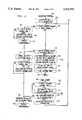
- FIGS. 2-3are a flow diagram of a network call coverage procedure of a PBX of FIG. 1 which is sending a call to coverage;
- FIG. 4is a flow diagram of a network call coverage procedure of a PBX of FIG. 1 which is receiving a call for coverage;
- FIG. 5is a flow diagram of bridging-related procedures of the sending and receiving PBXs of FIG. 1 for a covered network call.
- FIG. 6is a flow diagram of the procedures of the sending and receiving PBXs of FIG. 1 in effecting a CONSULT call for a covered network call.
- FIG. 1shows a network of telecommunications switches.
- the networkis illustratively a private telecommunications network made up of private branch exchanges (PBXs) 10 and 20, such as the AT&T Definity® G3 PBXs.
- PBXsprivate branch exchanges
- the networkcould just as well be a public network made up of central office switches, a hybrid :network, a data network, or any other telecommunications network that comprises a plurality of nodes.
- the illustrative networkincludes at least two switches (also called switching systems) that are interconnected by a network 9.
- Network 9could be a straight-through interconnection between the two switches, or a tandem switch, or a network of a plurality of interconnected switches such as the public telephone network, etc.
- the form of network 9is irrelevant for purposes of this invention.
- each PBX 10 and 20serves its own complement of communications endpoints, also called terminals, 11-12 and 21-22, respectively.
- Each PBX 10 and 20is connected to network 9 by a plurality of user-communications links 15 and 25, and control data signaling links 16 and 26, respectively.
- Links 15, 16, 25, and 26may take any form. Examples of possible links 15 and 25 are telephony trunks and ISDN bearer channels. Examples of possible links 16 and 26 are the AT&T DCIU link, a PBX application programmer interface (API) link, a DCS protocol link, or the ISDN D channel.
- links 15, 16, 25, and 26may be either separate physical links or separate channels on the same physical link.
- PBXs 10 and 20are illustratively stored-program-controlled entities; each PBX 10, 20 includes a processor 13, 23 which controls the operation of the PBX 10, 20, and a memory 14, 24 which stores control programs and data for use by processor 13, 23.
- Each coverage pathis associated with a different terminal 11-12, 21-22.
- Each coverage pathincludes a sequence of a plurality of entries 99.
- Each entry 99identifies a different endpoint or terminal to which incoming calls destined for the associated endpoint or terminal may be redirected.
- Included among the control programs stored in each of the memories 14 and 24are call coverage functions 130. Except for the functions 130, the telecommunications network shown in FIG. 1 is conventional. Hence, only the functions 130 will be described in any detail.
- FIGS. 2-6The operations carried out by PBXs 10 and 20 under control of functions 130 are diagrammed in FIGS. 2-6.
- PBX 10For purposes of illustration, assume that PBX 10 has received an incoming call for terminal 11, the call cannot be completed to or is not answered by terminal 11, and terminal 11 has call coverage activated. In response, call coverage is invoked for the call by covered PBX 10, at step 200 of FIG. 2, in order to determine where this covered call should be redirected to. Since redirection will be dictated by coverage path 110 that is associated with the original call destination--the covered terminal 11--coverage path 110 will henceforth be referred to as the coverage path "of the call". Covered PBX 10 accesses the first entry 99 in that coverage path 110 of the call in order to determine from its contents the--endpoint the covering terminal--to which the call should be redirected, at step 202.
- Covered PBX 10determines whether the covering terminal is local or remote, in a conventional manner, at step 204. If the covering terminal is local, i.e., directly served by covered PBX 10, covered PBX 10 checks whether there is a previous covering point for the call, at step 205. Since this is the first attempt at call coverage for this call, the determination at step 205 is negative. However, for all subsequent attempts, the determination will be affirmative, causing covered PBX 10 to tear down any call path that it had set up for the covered call to that previous covering point, at step 206. Following step 205 or 206, covered PBX 10 proceeds to try and redirect the call to the local covering terminal in the conventional manner, at step 207. If the coverage attempt at step 207 should not succeed, covered PBX 10 will proceed to steps 232 et seq.
- covered PBX 10determines at step 204 that the covering terminal is remote, i.e., served by another switch--PBX 20 in this illustrative example--covered PBX 10 proceeds to determine whether the covering switch is a "cooperating" switch, at step 210.
- a "cooperating" switchis one that has been configured to effect network call coverage, like PBX 10.
- covered PBX 10makes the determination based on whether the covering terminal has a telephone number (decoded extension) that is within the same network numbering plan as is implemented on covered PBX 10: all switches within the network numbering plan are assumed to be "cooperating" switches.
- each entry 99may contain an explicit indicator, e.g., a flag, that indicates whether the covering endpoint is served by a "cooperating" switch.
- an explicit indicatore.g., a flag
- itestablishes a call connection for the call to covering PBX 20 over trunks 15, 25, and connects the call therethrough to covering PBX 20, at step 212, in a conventional manner.
- Covered PBX 10also checks whether there is a previous covering point for the call, at step 214. The answer is negative for the first coverage endpoint in the call's coverage path, and affirmative for all subsequent endpoints.
- covered PBX 10tears down the call path that it had set up for the covered call to that previous covering point, at step 216.
- covering PBX 20conventionally takes over control of the call, causing covered PBX 10 to relinquish control thereover, at step 244.
- the callis now handled conventionally, like any other inter-PBX call, at step 246.
- covered PBX 10determines at step 210 that covering PBX 20 is a "cooperating" switch, it sends a data message to covering PBX 20 over control data signaling links 16, 26, which identifies the call as a network coverage call and conveys a call ID for the call, at step 220.
- covered PBX 10establishes a call connection for the call to covering PBX 20 over trunks 15, 25, and connects the call therethrough to covering PBX 20, at step 222. Covered PBX 10 then starts a response timer, at step 224, and waits for a response from covering PBX 20, at step 226.
- covered PBX 10checks whether there is a previous covering point for the call, at step 230. If so, covered PBX 10 tears down the call path that it had set up for the covered call at step 222 to the present covering PBX 20, at step 231, and then proceeds to step 232. If there is not a previous covering point for the call, covered PBX 10 proceeds directly to step 232. At step 232, covered PBX 10 checks the call's coverage path 110 to determine if it contains any more entries 99.
- the call's coverage pathcontains no more entries 99
- covered PBX 10relinquishes control of the call to covering PBX 20, at step 244, in the same manner as it would for any inter-PBX call that it has connected to PBX 20.
- the callis henceforth handled conventionally, as any other inter-PBX call, at step 246.
- covered PBX 10accesses the next entry 99 in the call's coverage path 110, at step 236, and proceeds to repeat steps 204 et seq. to cover the call to the next covering terminal.
- the message which covered PBX 10 sent to covering PBX 20 at step 220is received by covering PBX 20 at step 400 of FIG. 4.
- covering PBX 20tries to interpret it, at step 402. If it cannot interpret the message, covering PBX 20 merely discards it, at step 404. Since, as a consequence, covering PBX 20 does not know that the call that is being extended by PBX 10 to PBX 20 is a network coverage call, covering PBX 20 will handle the call conventionally, like any other inter-PBX call. However, if covering PBX 20 can interpret the message from covered PBX 10 at step 402, it learns that the extended call is a network coverage call.
- covering PBX 20determines the destination--the covering terminal--of the extended call, at step 406. Assuming that terminal 22 is specified as the covering terminal, covering PBX 20 then checks in a conventional manner whether the covering terminal 22 is available to receive the call, at step 408. If the covering terminal 22 is not available, covering PBX 20 returns a reply message to covered PBX 10 via control data signaling links 26, 16, indicating the unavailable status and also the endpoint type of covering terminal 22, at step 410. Control of the call is thereby relinquished by covering PBX 20 and is passed back to covered PBX 10, at step 412, and involvement of covering PBX 20 in the call coverage ends, at step 414.
- covering PBX 20determines whether the covering terminal 22 is a member of a coverage group, e.g., a hunt group, at step 418. If it is a member of a hunt group, no further coverage is needed for the covered call. Covering PBX 20 then returns a reply message to covered PBX 10 via control data signaling links 26, 16 indicating the available status and the endpoint type of the covering terminal 22, and whether or not further coverage is needed for the covered call, at step 420. Covering PBX 20 also turns off call coverage for the covering terminal 22 on PBX 20, at step 422, in a conventional manner.
- a coverage groupe.g., a hunt group
- Covering PBX 20then undertakes to connect the covered call to the covering terminal 22, at step 424. This includes ringing the covering terminal 22 to alert it to the presence of the call.
- the callis henceforth handled conventionally, like any other inter-PBX call, at step 426.
- covered PBX 10checks whether the reply message indicates that the covering terminal is available, at step 302. If the reply message indicates that the covering terminal is not available, covered PBX 10 tears down the call path that it has set up for the call to covering PBX 20 at step 222, at step 380, so as to disconnect the call from the covering PBX 20. Covered PBX 10 then checks whether there are more entries 99 in the call's coverage path 110, at step 382. If not, covered PBX 10 proceeds conventionally as it would proceed if there were no coverage path for the call, at step 384. This normally involves terminating the call. If there are more entries 99 in the call's coverage path, covered PBX 10 accesses the next entry 99, at step 386, and then returns to steps 204 et seq. to cover the call to the next covering terminal.
- covered PBX 10checks whether there is a previous covering point for the call, at step 303. If so, covered PBX 10 tears down the call path that it had set up for the covered call to that previous covering point, at step 304. Following step 303 or 304, covered PBX 10 checks the contents of the message that it had received at step 300 to determine whether further coverage is needed for this call, at step 305. If further coverage is not needed, covered PBX 10 proceeds to step 312 to complete the call in a conventional manner like any other inter-PBX call. If further coverage is needed, covered PBX 10 starts a ringing timer, at step 306, and waits, at step 308.
- the ringing timerlimits how long the covering terminal is allowed to keep the covered call unanswered. If, before the ringing timer expires, covered PBX 10 detects, in a conventional manner such as from signaling on trunks 25, 15, that the call has been answered by the covering terminal, at step 310, covered PBX 10 proceeds to complete the call conventionally like any other answered inter-PBX call, at step 312. If, however, the ringing timer expires before call answer is detected, at step 320, covered PBX 10 checks whether there are more entries 99 in the coverage path 110 of the call, at step 322.
- covered PBX 10proceeds to treat the call conventionally like as any other inter-PBX call, at step 326, relinquishing control of the call to covering PBX 20 in the process, at step 324. If covered PBX 10 finds at step 322 that there are more entries 99 in the coverage path 110, it accesses the next entry 99 in the coverage path 110, at step 328, and checks whether the covering terminal designated by that accessed entry 99 is local or remote, at step 330. (This terminal now becomes the new "present" covering terminal in the terminology of the Figures.) If this covering terminal is local, covered PBX 10 checks whether this covering terminal is available to receive the call, at step 332.
- covered PBX 10If the local covering terminal is not available, covered PBX 10 returns to step 322. If the local covering terminal is available, covered PBX 10 covers the call to the local covering terminal at step 333, and then tears down the call path to PBX 20, at step 334, so as to disconnect the call from PBX 20. Covered PBX 10 then handles the call to the local covering terminal conventionally as a local call, at step 336.
- PBX 10determines there that the specified covering terminal is a remote endpoint, it checks at step 340 whether the covering switch that serves this remote covering endpoint is a "cooperating" switch, in the manner described above for step 210 of FIG. 2. (The new covering switch may again be PBX 20.) If the covering switch is determined not to be a "cooperating" switch, covered PBX 10 tears down the call path to the previous covering switch (PBX 20) that it had established at step 222 of FIG. 2, at step 342, so as to disconnect the call from the previous covering switch, and instead extends the call's path to the new covering switch, at step 344, in order to cover the call to the remote covering endpoint. The new covering switch now conventionally takes over control of the call, causing covered PBX 10 to relinquish control thereover, at step 346. The call is now handled conventionally, like any other inter-switch call, at step 348.
- covered PBX 10determines at step 340 that the new covering switch is a "cooperating" switch, it sends a data message thereto over the control data signaling link 16, which message identifies the call as a network coverage call and conveys a call ID for the call, at step 350.
- covered PBX 10establishes a call connection for the call to this covering switch over trunk 15, and connects the call therethrough to this covering switch, at step 352.
- Covered PBX 10then starts the response timer, at step 354, and waits for a response from this covering switch, at step 356.
- the covering switchresponds to the message from covered PBX 10 in the manner shown in FIG. 4 and described above in conjunction therewith. If the response timer expires before covered PBX 10 receives a reply message from the covering switch, at step 360, covered PBX 10 tears down the call path that it has set up for the call to the previous covering switch (PBX 20) at step 222, at step 362, in order to disconnect the call from the previous covering switch, and then proceeds to steps 346 et seq. If the reply is received before the response timer expires, at step 370, covered PBX 10 analyzes the reply to determine if the covering terminal is available, at step 372. If the covering terminal is available, covered PBX 10 returns to steps 303 et seq.
- covered PBX 10tears down the call path that it had set up for the call to the new covering switch at step 352, at step 374, in order to disconnect the call from the new covering switch, and then returns to steps 322 et seq.
- covered PBX 10If the call is eventually answered by a covering terminal, whether local or remote, covered PBX 10 detects it, at step 500 of FIG. 5, and in response covered PBX 10 sets up the capability to bridge a call appearance of the original destination terminal 11 onto the call, at step 502, in a conventional manner via a bridging arrangement 100. This is shown in FIG. 1, where terminal 12 is assumed to be the call-originating terminal.
- covered PBX 10responds by sending a message via control data signaling link 16 to the covering switch--assume PBX 20--that serves the covering terminal--assume terminal 22--that answered the call, at step 506, to inform it that the covered terminal has been bridged onto the call.
- Covering PBX 20receives the message, at step 510, and tries to interpret it, at step 512. If covering PBX 20 cannot interpret the message, it discards it, at step 514.
- covering PBX 20can interpret the message, it responds by checking its administration data 170, at step 516, to determine, at step 518, whether it is administered to drop the covering terminal from a covered call when the covered terminal bridges onto the call. If not, it discards the message, at step 520; if so, it checks, at step 519, whether the covered call is on hold at covering terminal 22. If the covered call is not on hold, covering PBX 20 merely discards the message that it received at step 510, at step 520.
- covering PBX 20drops the covering terminal 22 and terminates the call at covering PBX 20, i.e., terminates the portion of the call extending between covered PBX 10 and covering PBX 20, at step 522, in a conventional manner in cooperation with covered PBX 10.
- Some terminalssuch as terminal 22 whose principal function is to serve as covering terminals, are each conventionally equipped with a CONSULT button 190. While endpoint terminal 22 is connected to a covered call, pressing of the CONSULT button results in a special priority call being established between terminal 22 and the original destination terminal of the covered call, whereby the party that answered the covered call at terminal 22 can consult about the covered call with the intended recipient of the call and obtain instructions about how to handle the covered call. While the use of the CONSULT button for calls that are covered on the same switch as serves the originate call destination is conventional, according to a further aspect of the invention, the CONSULT capability is also extended to network coverage calls. This is illustrated in FIG. 6.
- covering PBX 20places the covered call on hold (as a part of the TRANSFER or CONFERENCE function), at step 602, and examines the call record 180 of this call, at step 604, to determine if its origin is local or remote, at step 606. If the call is local, covering PBX 20 processes it in the conventional manner for a CONSULT call, at step 608.
- covering PBX 20examines the call record 180 further to determine if the remote switch is a "cooperating" switch, at step 610. If the call is not indicated to be a cooperating switch, covering PBX 20 indicates to terminal 22 its inability to comply with the CONSULT request, at step 612. Such an indication may be, for example, flashing of a lamp on the terminal's CONSULT button, or an intercept tone, or a recorded message. Covering PBX 20 then continues to handle the covered call conventionally, at step 614.
- covering PBX 20knows, from the message about the covered call that it had received from covered PBX 10 at step 400 of FIG. 4, that covered PBX 10 is also a "cooperating" switch, and it knows the call ID of the call. Covering PBX 20 therefore sets up a new call from terminal 22 to covered PBX 10 over trunks 25, 15, at step 620, and at the same time sends a message to covered PBX 10 over control data signal links 26, 16, identifying the new call as a CONSULT call for the covered call whose ID it also includes in the message, at step 622.
- Covered PBX 10receives the message, at step 630 and in response it drops the bridge connection of the covered terminal 11 from the covered call, at step 632 and rings the terminal 11, at step 634. If terminal 11 answers, at step 640, covered PBX 10 connects the CONSULT call to terminal 11, at step 642. Henceforth, covered PBX 10 handles the CONSULT call conventionally, like any other inter-PBX call, at step 644.
- terminal 11 or 22hangs up, at steps 650 or 652, respectively, or when the party at covering terminal 22 presses the line appearance button of the covered call, at step 654, covering PBX 20 tears down the CONSULT call in conventional cooperation with covered PBX 10, at step 656, and reconnects the covered call to terminal 22, at step 658. Covering PBX 20 then proceeds with conventional handling of the covered call, at step 660.
- the covered callcan be transferred by the covering party to the covered terminal, or the covering party can conference in the covered terminal and then either remain on the call or drop out.
- the covering partycan conference in the covered terminal and then either remain on the call or drop out.
Landscapes
- Engineering & Computer Science (AREA)
- Computer Networks & Wireless Communication (AREA)
- Signal Processing (AREA)
- Physics & Mathematics (AREA)
- Astronomy & Astrophysics (AREA)
- General Physics & Mathematics (AREA)
- Exchange Systems With Centralized Control (AREA)
- Data Exchanges In Wide-Area Networks (AREA)
- Telephonic Communication Services (AREA)
Abstract
Description
Claims (33)
Priority Applications (2)
| Application Number | Priority Date | Filing Date | Title |
|---|---|---|---|
| US08/413,141US5521970A (en) | 1995-03-29 | 1995-03-29 | Arrangement for extending call-coverage across a network of nodes |
| CA002167236ACA2167236C (en) | 1995-03-29 | 1996-01-15 | Arrangement for extending call-coverage across a network of nodes |
Applications Claiming Priority (1)
| Application Number | Priority Date | Filing Date | Title |
|---|---|---|---|
| US08/413,141US5521970A (en) | 1995-03-29 | 1995-03-29 | Arrangement for extending call-coverage across a network of nodes |
Publications (1)
| Publication Number | Publication Date |
|---|---|
| US5521970Atrue US5521970A (en) | 1996-05-28 |
Family
ID=23636018
Family Applications (1)
| Application Number | Title | Priority Date | Filing Date |
|---|---|---|---|
| US08/413,141Expired - LifetimeUS5521970A (en) | 1995-03-29 | 1995-03-29 | Arrangement for extending call-coverage across a network of nodes |
Country Status (2)
| Country | Link |
|---|---|
| US (1) | US5521970A (en) |
| CA (1) | CA2167236C (en) |
Cited By (15)
| Publication number | Priority date | Publication date | Assignee | Title |
|---|---|---|---|---|
| WO1998015134A1 (en)* | 1996-09-30 | 1998-04-09 | Siemens Aktiengesellschaft | Communications system consisting of at least two private branch exchanges with team function |
| WO1998015104A1 (en)* | 1996-09-30 | 1998-04-09 | Siemens Aktiengesellschaft | Communications system consisting of at least two private branch exchanges (pbx) with team function |
| US5818921A (en)* | 1996-03-14 | 1998-10-06 | Siemens Business Communication Systems, Inc. | Signaling system and method for enabling PBX-PBX feature transparency across a switched public network |
| US5867568A (en)* | 1996-08-22 | 1999-02-02 | Lucent Technologies Inc. | Coverage of redirected calls |
| GB2339110A (en)* | 1998-07-02 | 2000-01-12 | Siemens Inf & Comm Networks | Network call parking service |
| US6023505A (en)* | 1997-07-11 | 2000-02-08 | Bellsouth Intellectual Property Corporation | System and method for providing a busy signal to a communication |
| EP0966142A3 (en)* | 1998-06-15 | 2000-04-05 | Lucent Technologies Inc. | Apparatus method and system for controlling secondary treatment by a distant switch for multiple leg telecommunication sessions |
| US20020009186A1 (en)* | 2000-03-31 | 2002-01-24 | Ian Catley | Method for call forwarding in a communications network |
| US6393016B2 (en)* | 1995-09-18 | 2002-05-21 | Net2Phone, Inc. | Telephony signal transmission over a data communications network |
| US20030091028A1 (en)* | 1997-07-25 | 2003-05-15 | Chang Gordon K. | Apparatus and method for integrated voice gateway |
| US20030114147A1 (en)* | 2001-12-13 | 2003-06-19 | Goss Stephen C. | Hold service on wireless calls |
| CN1118199C (en)* | 1996-09-30 | 2003-08-13 | 西门子公司 | Communication system consisting of at least two private branch exchanges (PBX) with team function |
| US6633591B2 (en)* | 1997-02-26 | 2003-10-14 | Fujitsu Limited | Switch device and system |
| US20060126382A1 (en)* | 2004-12-09 | 2006-06-15 | Eduardo Maayan | Method for reading non-volatile memory cells |
| US7492887B1 (en)* | 1998-12-22 | 2009-02-17 | Siemens Communications | Network group pickup |
Citations (23)
| Publication number | Priority date | Publication date | Assignee | Title |
|---|---|---|---|---|
| US4150257A (en)* | 1977-10-31 | 1979-04-17 | Bell Telephone Laboratories, Incorporated | Communication system call coverage arrangements |
| US4313036A (en)* | 1980-02-19 | 1982-01-26 | Rolm Corporation | Distributed CBX system employing packet network |
| US4436963A (en)* | 1982-03-30 | 1984-03-13 | Bell Telephone Laboratories, Incorporated | Implied principal addressing in a call coverage arrangement |
| US4436962A (en)* | 1982-03-30 | 1984-03-13 | Bell Telephone Laboratories, Incorporated | Call coverage arrangement |
| US4488004A (en)* | 1982-03-30 | 1984-12-11 | At&T Bell Laboratories | Providing feature transparency between a plurality of PBXs |
| US5062103A (en)* | 1988-12-29 | 1991-10-29 | At&T Bell Laboratories | Telephone agent call management system |
| US5206901A (en)* | 1991-12-23 | 1993-04-27 | At&T Bell Laboratories | Method and apparatus for alerting multiple telephones for an incoming call |
| US5237604A (en)* | 1991-06-28 | 1993-08-17 | At&T Bell Laboratories | Arrangement for serving a telephone office code from two switching systems |
| US5247571A (en)* | 1992-02-28 | 1993-09-21 | Bell Atlantic Network Services, Inc. | Area wide centrex |
| US5282244A (en)* | 1991-06-24 | 1994-01-25 | At&T Bell Laboratories | Virtual signaling network method |
| US5311585A (en)* | 1992-04-14 | 1994-05-10 | At&T Bell Laboratories | Carrier proportioned routing |
| US5313459A (en)* | 1992-10-08 | 1994-05-17 | Newton Communications, Inc. | Private branch exchange system and methods for operating same |
| US5329581A (en)* | 1991-12-23 | 1994-07-12 | At&T Bell Laboratories | Target area calling system |
| US5329578A (en)* | 1992-05-26 | 1994-07-12 | Northern Telecom Limited | Personal communication service with mobility manager |
| US5335268A (en)* | 1992-10-22 | 1994-08-02 | Mci Communications Corporation | Intelligent routing of special service telephone traffic |
| US5353339A (en)* | 1992-05-20 | 1994-10-04 | At&T Bell Laboratories | Simplified uniform network provisioning and restoration |
| US5369695A (en)* | 1992-01-06 | 1994-11-29 | At&T Corp. | Method of redirecting a telephone call to an alternate destination |
| US5377262A (en)* | 1991-12-30 | 1994-12-27 | At&T Corp. | Telecommunication switching system having adaptive routing switching nodes |
| US5390242A (en)* | 1991-12-30 | 1995-02-14 | At&T Corp. | Rerouting in a distributed telecommunication system |
| US5404350A (en)* | 1993-04-22 | 1995-04-04 | At&T Corp. | Routing calls destined for inaccessible destinations |
| US5450482A (en)* | 1992-12-29 | 1995-09-12 | At&T Corp. | Dynamic network automatic call distribution |
| US5455855A (en)* | 1993-02-12 | 1995-10-03 | Nec Corporation | System for connecting public network subscriber and private network subscriber |
| US5459779A (en)* | 1994-02-25 | 1995-10-17 | At&T Ipm Corp. | Method for switching telephone calls to information service providers |
- 1995
- 1995-03-29USUS08/413,141patent/US5521970A/ennot_activeExpired - Lifetime
- 1996
- 1996-01-15CACA002167236Apatent/CA2167236C/ennot_activeExpired - Fee Related
Patent Citations (23)
| Publication number | Priority date | Publication date | Assignee | Title |
|---|---|---|---|---|
| US4150257A (en)* | 1977-10-31 | 1979-04-17 | Bell Telephone Laboratories, Incorporated | Communication system call coverage arrangements |
| US4313036A (en)* | 1980-02-19 | 1982-01-26 | Rolm Corporation | Distributed CBX system employing packet network |
| US4436963A (en)* | 1982-03-30 | 1984-03-13 | Bell Telephone Laboratories, Incorporated | Implied principal addressing in a call coverage arrangement |
| US4436962A (en)* | 1982-03-30 | 1984-03-13 | Bell Telephone Laboratories, Incorporated | Call coverage arrangement |
| US4488004A (en)* | 1982-03-30 | 1984-12-11 | At&T Bell Laboratories | Providing feature transparency between a plurality of PBXs |
| US5062103A (en)* | 1988-12-29 | 1991-10-29 | At&T Bell Laboratories | Telephone agent call management system |
| US5282244A (en)* | 1991-06-24 | 1994-01-25 | At&T Bell Laboratories | Virtual signaling network method |
| US5237604A (en)* | 1991-06-28 | 1993-08-17 | At&T Bell Laboratories | Arrangement for serving a telephone office code from two switching systems |
| US5206901A (en)* | 1991-12-23 | 1993-04-27 | At&T Bell Laboratories | Method and apparatus for alerting multiple telephones for an incoming call |
| US5329581A (en)* | 1991-12-23 | 1994-07-12 | At&T Bell Laboratories | Target area calling system |
| US5390242A (en)* | 1991-12-30 | 1995-02-14 | At&T Corp. | Rerouting in a distributed telecommunication system |
| US5377262A (en)* | 1991-12-30 | 1994-12-27 | At&T Corp. | Telecommunication switching system having adaptive routing switching nodes |
| US5369695A (en)* | 1992-01-06 | 1994-11-29 | At&T Corp. | Method of redirecting a telephone call to an alternate destination |
| US5247571A (en)* | 1992-02-28 | 1993-09-21 | Bell Atlantic Network Services, Inc. | Area wide centrex |
| US5311585A (en)* | 1992-04-14 | 1994-05-10 | At&T Bell Laboratories | Carrier proportioned routing |
| US5353339A (en)* | 1992-05-20 | 1994-10-04 | At&T Bell Laboratories | Simplified uniform network provisioning and restoration |
| US5329578A (en)* | 1992-05-26 | 1994-07-12 | Northern Telecom Limited | Personal communication service with mobility manager |
| US5313459A (en)* | 1992-10-08 | 1994-05-17 | Newton Communications, Inc. | Private branch exchange system and methods for operating same |
| US5335268A (en)* | 1992-10-22 | 1994-08-02 | Mci Communications Corporation | Intelligent routing of special service telephone traffic |
| US5450482A (en)* | 1992-12-29 | 1995-09-12 | At&T Corp. | Dynamic network automatic call distribution |
| US5455855A (en)* | 1993-02-12 | 1995-10-03 | Nec Corporation | System for connecting public network subscriber and private network subscriber |
| US5404350A (en)* | 1993-04-22 | 1995-04-04 | At&T Corp. | Routing calls destined for inaccessible destinations |
| US5459779A (en)* | 1994-02-25 | 1995-10-17 | At&T Ipm Corp. | Method for switching telephone calls to information service providers |
Non-Patent Citations (12)
| Title |
|---|
| "G3V2 Feature Description", AT&T document No. 555-230-204, Issue 1, Jul. 1993, pp. 3-301-3-314. |
| "G3V2 Implementation", AT&T document No. 555-230-653, Issue 1, Jul. 1993, pp. 3-113-3-118. |
| "G3V2 Implementation", AT&T document No. 555-230-653, Issue 1, Jul. 1993, pp. 3-169-3-172. |
| "G3V3 Implementation" AT&T document No. 555-230-653, Issue 1, Jul. 1993, (Addendum to AT&T 555-230-653), pp. 5-251-5-252; 3-432a-3-432d. |
| "G3V3 Implementation", AT&T document No. 555-230-653B, Issue 2, Mar. 1994, pp. 413-416. |
| Excerpts from "Based on DefinityR Generic 2.1, Issue 3.1 Health, Education and Safety Package, Feature Package PG-3W104", AT&T Specification No. SD 6213, May 4, 1992, pp. 11-13; 19-21; 26-27. |
| Excerpts from Based on Definity R Generic 2.1, Issue 3.1 Health, Education and Safety Package, Feature Package PG 3W104 , AT&T Specification No. SD 6213, May 4, 1992, pp. 11 13; 19 21; 26 27.* |
| G3V2 Feature Description , AT&T document No. 555 230 204, Issue 1, Jul. 1993, pp. 3 301 3 314.* |
| G3V2 Implementation , AT&T document No. 555 230 653, Issue 1, Jul. 1993, pp. 3 113 3 118.* |
| G3V2 Implementation , AT&T document No. 555 230 653, Issue 1, Jul. 1993, pp. 3 169 3 172.* |
| G3V3 Implementation , AT&T document No. 555 230 653B, Issue 2, Mar. 1994, pp. 413 416.* |
| G3V3 Implementation AT&T document No. 555 230 653, Issue 1, Jul. 1993, (Addendum to AT&T 555 230 653), pp. 5 251 5 252; 3 432a 3 432d.* |
Cited By (24)
| Publication number | Priority date | Publication date | Assignee | Title |
|---|---|---|---|---|
| US6393016B2 (en)* | 1995-09-18 | 2002-05-21 | Net2Phone, Inc. | Telephony signal transmission over a data communications network |
| US5818921A (en)* | 1996-03-14 | 1998-10-06 | Siemens Business Communication Systems, Inc. | Signaling system and method for enabling PBX-PBX feature transparency across a switched public network |
| EP0836336A3 (en)* | 1996-08-22 | 2000-05-10 | Lucent Technologies Inc. | Coverage of redirected calls |
| US5867568A (en)* | 1996-08-22 | 1999-02-02 | Lucent Technologies Inc. | Coverage of redirected calls |
| US6320954B1 (en) | 1996-09-30 | 2001-11-20 | Siemens Aktiengesellschaft | Communication system consisting of at least two private branch exchanges with a team function |
| WO1998015134A1 (en)* | 1996-09-30 | 1998-04-09 | Siemens Aktiengesellschaft | Communications system consisting of at least two private branch exchanges with team function |
| DE19640265B4 (en)* | 1996-09-30 | 2007-11-29 | Siemens Ag | Communication system consisting of at least two private branch exchanges with team function |
| CN1118199C (en)* | 1996-09-30 | 2003-08-13 | 西门子公司 | Communication system consisting of at least two private branch exchanges (PBX) with team function |
| WO1998015104A1 (en)* | 1996-09-30 | 1998-04-09 | Siemens Aktiengesellschaft | Communications system consisting of at least two private branch exchanges (pbx) with team function |
| CN1109445C (en)* | 1996-09-30 | 2003-05-21 | 西门子公司 | Communications system consisting of at least private branch exchanges with team function |
| US6633591B2 (en)* | 1997-02-26 | 2003-10-14 | Fujitsu Limited | Switch device and system |
| US6023505A (en)* | 1997-07-11 | 2000-02-08 | Bellsouth Intellectual Property Corporation | System and method for providing a busy signal to a communication |
| US7280530B2 (en) | 1997-07-25 | 2007-10-09 | Starvox Communications Inc. | Apparatus and method for integrated voice gateway |
| US20030091028A1 (en)* | 1997-07-25 | 2003-05-15 | Chang Gordon K. | Apparatus and method for integrated voice gateway |
| US20030095541A1 (en)* | 1997-07-25 | 2003-05-22 | Chang Gordon K. | Apparatus and method for integrated voice gateway |
| US20030095542A1 (en)* | 1997-07-25 | 2003-05-22 | Chang Gordon K. | Apparatus and method for integrated voice gateway |
| EP0966142A3 (en)* | 1998-06-15 | 2000-04-05 | Lucent Technologies Inc. | Apparatus method and system for controlling secondary treatment by a distant switch for multiple leg telecommunication sessions |
| GB2339110B (en)* | 1998-07-02 | 2003-08-20 | Siemens Inf & Comm Networks | Network call park service |
| US6473437B2 (en) | 1998-07-02 | 2002-10-29 | Siemens Information And Communication Networks, Inc. | Network call park service |
| GB2339110A (en)* | 1998-07-02 | 2000-01-12 | Siemens Inf & Comm Networks | Network call parking service |
| US7492887B1 (en)* | 1998-12-22 | 2009-02-17 | Siemens Communications | Network group pickup |
| US20020009186A1 (en)* | 2000-03-31 | 2002-01-24 | Ian Catley | Method for call forwarding in a communications network |
| US20030114147A1 (en)* | 2001-12-13 | 2003-06-19 | Goss Stephen C. | Hold service on wireless calls |
| US20060126382A1 (en)* | 2004-12-09 | 2006-06-15 | Eduardo Maayan | Method for reading non-volatile memory cells |
Also Published As
| Publication number | Publication date |
|---|---|
| CA2167236C (en) | 1999-03-30 |
| CA2167236A1 (en) | 1996-09-30 |
Similar Documents
| Publication | Publication Date | Title |
|---|---|---|
| US5850434A (en) | Telecommunications network | |
| US5099509A (en) | Integration of voice store and forward facility | |
| US5583929A (en) | Customer oriented telecommunications network | |
| EP0510861B1 (en) | Method of rerouting telecommunications traffic | |
| EP0550975B1 (en) | A method of redirecting a telephone call to an alternate destination | |
| US5416834A (en) | Redirection of calls by a communication terminal | |
| US5521970A (en) | Arrangement for extending call-coverage across a network of nodes | |
| US5598458A (en) | Telecommunication switching system having transparent wireless features | |
| US4445211A (en) | Arrangement for multiple custom calling | |
| US5390241A (en) | Shared line appearance across a plurality of switching systems | |
| US5867568A (en) | Coverage of redirected calls | |
| JPH07273902A (en) | Call origination of audio and data independently switched for use in simultaneous audio and data modem | |
| US5937035A (en) | Interswitch telephone status monitoring | |
| US5249219A (en) | Integration of voice store and forward facility | |
| CA2238169C (en) | A system for connecting calls on physically distinct servers on an advanced intelligent network | |
| EP0430534B1 (en) | Control of non-locally switched telecommunication services | |
| US5303290A (en) | System for elminating glare in virtual private line circuits | |
| US5644632A (en) | Distributed key telephone station network | |
| US4446553A (en) | Arrangement for multiple custom calling | |
| JP2708152B2 (en) | Dial tone detection method with detection notification function | |
| EP1269769B1 (en) | Computer telephony integration | |
| US5608790A (en) | Trunk utilization in a telecommunications network | |
| EP0748133B1 (en) | Method for operating a telecommunications network and associated network | |
| CA2212311C (en) | Coverage of redirected calls | |
| US6427007B1 (en) | System and method for completing a call while at least one call is established using analog interface to telephone network |
Legal Events
| Date | Code | Title | Description |
|---|---|---|---|
| AS | Assignment | Owner name:AT&T IPM CORP., FLORIDA Free format text:ASSIGNMENT OF ASSIGNORS INTEREST;ASSIGNORS:HERRICK, DONNA W.;MEIS, RICKIE EUGENE;REEL/FRAME:007424/0710 Effective date:19950329 | |
| STCF | Information on status: patent grant | Free format text:PATENTED CASE | |
| FEPP | Fee payment procedure | Free format text:PAYOR NUMBER ASSIGNED (ORIGINAL EVENT CODE: ASPN); ENTITY STATUS OF PATENT OWNER: LARGE ENTITY | |
| FPAY | Fee payment | Year of fee payment:4 | |
| AS | Assignment | Owner name:LUCENT TECHNOLOGIES, INC., NEW JERSEY Free format text:ASSIGNMENT OF ASSIGNORS INTEREST;ASSIGNOR:AT&T CORP.;REEL/FRAME:012754/0365 Effective date:19960329 Owner name:AVAYA TECHNOLOGY CORP., NEW JERSEY Free format text:ASSIGNMENT OF ASSIGNORS INTEREST;ASSIGNOR:LUCENT TECHNOLOGIES INC.;REEL/FRAME:012754/0770 Effective date:20000929 | |
| AS | Assignment | Owner name:BANK OF NEW YORK, THE, NEW YORK Free format text:SECURITY AGREEMENT;ASSIGNOR:AVAYA TECHNOLOGY CORP.;REEL/FRAME:012775/0149 Effective date:20020405 | |
| FPAY | Fee payment | Year of fee payment:8 | |
| FPAY | Fee payment | Year of fee payment:12 | |
| AS | Assignment | Owner name:CITIBANK, N.A., AS ADMINISTRATIVE AGENT, NEW YORK Free format text:SECURITY AGREEMENT;ASSIGNORS:AVAYA, INC.;AVAYA TECHNOLOGY LLC;OCTEL COMMUNICATIONS LLC;AND OTHERS;REEL/FRAME:020156/0149 Effective date:20071026 Owner name:CITIBANK, N.A., AS ADMINISTRATIVE AGENT,NEW YORK Free format text:SECURITY AGREEMENT;ASSIGNORS:AVAYA, INC.;AVAYA TECHNOLOGY LLC;OCTEL COMMUNICATIONS LLC;AND OTHERS;REEL/FRAME:020156/0149 Effective date:20071026 | |
| AS | Assignment | Owner name:CITICORP USA, INC., AS ADMINISTRATIVE AGENT, NEW Y Free format text:SECURITY AGREEMENT;ASSIGNORS:AVAYA, INC.;AVAYA TECHNOLOGY LLC;OCTEL COMMUNICATIONS LLC;AND OTHERS;REEL/FRAME:020166/0705 Effective date:20071026 Owner name:CITICORP USA, INC., AS ADMINISTRATIVE AGENT, NEW YORK Free format text:SECURITY AGREEMENT;ASSIGNORS:AVAYA, INC.;AVAYA TECHNOLOGY LLC;OCTEL COMMUNICATIONS LLC;AND OTHERS;REEL/FRAME:020166/0705 Effective date:20071026 Owner name:CITICORP USA, INC., AS ADMINISTRATIVE AGENT,NEW YO Free format text:SECURITY AGREEMENT;ASSIGNORS:AVAYA, INC.;AVAYA TECHNOLOGY LLC;OCTEL COMMUNICATIONS LLC;AND OTHERS;REEL/FRAME:020166/0705 Effective date:20071026 | |
| AS | Assignment | Owner name:AVAYA INC., NEW JERSEY Free format text:REASSIGNMENT;ASSIGNOR:AVAYA TECHNOLOGY LLC;REEL/FRAME:021158/0290 Effective date:20080625 | |
| AS | Assignment | Owner name:AVAYA TECHNOLOGY LLC, NEW JERSEY Free format text:CONVERSION FROM CORP TO LLC;ASSIGNOR:AVAYA TECHNOLOGY CORP.;REEL/FRAME:022071/0420 Effective date:20051004 | |
| AS | Assignment | Owner name:BANK OF NEW YORK MELLON TRUST, NA, AS NOTES COLLATERAL AGENT, THE, PENNSYLVANIA Free format text:SECURITY AGREEMENT;ASSIGNOR:AVAYA INC., A DELAWARE CORPORATION;REEL/FRAME:025863/0535 Effective date:20110211 Owner name:BANK OF NEW YORK MELLON TRUST, NA, AS NOTES COLLAT Free format text:SECURITY AGREEMENT;ASSIGNOR:AVAYA INC., A DELAWARE CORPORATION;REEL/FRAME:025863/0535 Effective date:20110211 | |
| AS | Assignment | Owner name:BANK OF NEW YORK MELLON TRUST COMPANY, N.A., THE, PENNSYLVANIA Free format text:SECURITY AGREEMENT;ASSIGNOR:AVAYA, INC.;REEL/FRAME:030083/0639 Effective date:20130307 Owner name:BANK OF NEW YORK MELLON TRUST COMPANY, N.A., THE, Free format text:SECURITY AGREEMENT;ASSIGNOR:AVAYA, INC.;REEL/FRAME:030083/0639 Effective date:20130307 | |
| AS | Assignment | Owner name:AVAYA INC., CALIFORNIA Free format text:BANKRUPTCY COURT ORDER RELEASING ALL LIENS INCLUDING THE SECURITY INTEREST RECORDED AT REEL/FRAME 025863/0535;ASSIGNOR:THE BANK OF NEW YORK MELLON TRUST, NA;REEL/FRAME:044892/0001 Effective date:20171128 Owner name:AVAYA INC. (FORMERLY KNOWN AS AVAYA TECHNOLOGY COR Free format text:BANKRUPTCY COURT ORDER RELEASING ALL LIENS INCLUDING THE SECURITY INTEREST RECORDED AT REEL/FRAME 012775/0149;ASSIGNOR:THE BANK OF NEW YORK;REEL/FRAME:044893/0266 Effective date:20171128 Owner name:AVAYA INC., CALIFORNIA Free format text:BANKRUPTCY COURT ORDER RELEASING ALL LIENS INCLUDING THE SECURITY INTEREST RECORDED AT REEL/FRAME 030083/0639;ASSIGNOR:THE BANK OF NEW YORK MELLON TRUST COMPANY, N.A.;REEL/FRAME:045012/0666 Effective date:20171128 | |
| AS | Assignment | Owner name:SIERRA HOLDINGS CORP., NEW JERSEY Free format text:RELEASE BY SECURED PARTY;ASSIGNOR:CITICORP USA, INC.;REEL/FRAME:045032/0213 Effective date:20171215 Owner name:AVAYA TECHNOLOGY, LLC, NEW JERSEY Free format text:RELEASE BY SECURED PARTY;ASSIGNOR:CITICORP USA, INC.;REEL/FRAME:045032/0213 Effective date:20171215 Owner name:OCTEL COMMUNICATIONS LLC, CALIFORNIA Free format text:RELEASE BY SECURED PARTY;ASSIGNOR:CITICORP USA, INC.;REEL/FRAME:045032/0213 Effective date:20171215 Owner name:AVAYA, INC., CALIFORNIA Free format text:RELEASE BY SECURED PARTY;ASSIGNOR:CITICORP USA, INC.;REEL/FRAME:045032/0213 Effective date:20171215 Owner name:VPNET TECHNOLOGIES, INC., NEW JERSEY Free format text:RELEASE BY SECURED PARTY;ASSIGNOR:CITICORP USA, INC.;REEL/FRAME:045032/0213 Effective date:20171215 |