US5521392A - Light cure system with closed loop control and work piece recording - Google Patents
Light cure system with closed loop control and work piece recordingDownload PDFInfo
- Publication number
- US5521392A US5521392AUS08/235,621US23562194AUS5521392AUS 5521392 AUS5521392 AUS 5521392AUS 23562194 AUS23562194 AUS 23562194AUS 5521392 AUS5521392 AUS 5521392A
- Authority
- US
- United States
- Prior art keywords
- light
- control
- intensity
- signals
- exposure
- Prior art date
- Legal status (The legal status is an assumption and is not a legal conclusion. Google has not performed a legal analysis and makes no representation as to the accuracy of the status listed.)
- Expired - Lifetime
Links
- 239000000463materialSubstances0.000claimsabstractdescription7
- 238000004519manufacturing processMethods0.000claimsdescription10
- 239000000835fiberSubstances0.000claimsdescription8
- 238000000034methodMethods0.000claimsdescription7
- 239000007788liquidSubstances0.000claimsdescription6
- 238000012544monitoring processMethods0.000claimsdescription3
- 238000013500data storageMethods0.000claims6
- 230000001276controlling effectEffects0.000claims4
- 230000002596correlated effectEffects0.000claims4
- 238000007789sealingMethods0.000claims3
- 238000003825pressingMethods0.000description22
- 239000000126substanceSubstances0.000description10
- 238000001723curingMethods0.000description9
- 239000000853adhesiveSubstances0.000description8
- 230000001070adhesive effectEffects0.000description8
- 230000015556catabolic processEffects0.000description6
- 238000006731degradation reactionMethods0.000description6
- 238000010586diagramMethods0.000description6
- 238000004891communicationMethods0.000description5
- 230000006870functionEffects0.000description5
- 230000004044responseEffects0.000description5
- 238000006243chemical reactionMethods0.000description2
- 230000001419dependent effectEffects0.000description2
- QSHDDOUJBYECFT-UHFFFAOYSA-NmercuryChemical compound[Hg]QSHDDOUJBYECFT-UHFFFAOYSA-N0.000description2
- 229910052753mercuryInorganic materials0.000description2
- 230000003287optical effectEffects0.000description2
- 238000000016photochemical curingMethods0.000description2
- 238000002428photodynamic therapyMethods0.000description2
- 238000001126phototherapyMethods0.000description2
- 238000006116polymerization reactionMethods0.000description2
- 229910052724xenonInorganic materials0.000description2
- FHNFHKCVQCLJFQ-UHFFFAOYSA-Nxenon atomChemical compound[Xe]FHNFHKCVQCLJFQ-UHFFFAOYSA-N0.000description2
- 150000001875compoundsChemical class0.000description1
- 230000003247decreasing effectEffects0.000description1
- 238000013461designMethods0.000description1
- 230000000694effectsEffects0.000description1
- 238000005516engineering processMethods0.000description1
- 239000013305flexible fiberSubstances0.000description1
- 229910052736halogenInorganic materials0.000description1
- 150000002367halogensChemical class0.000description1
- 230000000977initiatory effectEffects0.000description1
- 239000004973liquid crystal related substanceSubstances0.000description1
- 230000003647oxidationEffects0.000description1
- 238000007254oxidation reactionMethods0.000description1
- 230000002093peripheral effectEffects0.000description1
- 239000010453quartzSubstances0.000description1
- VYPSYNLAJGMNEJ-UHFFFAOYSA-Nsilicon dioxideInorganic materialsO=[Si]=OVYPSYNLAJGMNEJ-UHFFFAOYSA-N0.000description1
- 239000007787solidSubstances0.000description1
- 238000012360testing methodMethods0.000description1
- 238000012795verificationMethods0.000description1
Images


Classifications
- A—HUMAN NECESSITIES
- A61—MEDICAL OR VETERINARY SCIENCE; HYGIENE
- A61N—ELECTROTHERAPY; MAGNETOTHERAPY; RADIATION THERAPY; ULTRASOUND THERAPY
- A61N5/00—Radiation therapy
- A61N5/06—Radiation therapy using light
- A61N5/0613—Apparatus adapted for a specific treatment
- A61N5/062—Photodynamic therapy, i.e. excitation of an agent
- A—HUMAN NECESSITIES
- A61—MEDICAL OR VETERINARY SCIENCE; HYGIENE
- A61N—ELECTROTHERAPY; MAGNETOTHERAPY; RADIATION THERAPY; ULTRASOUND THERAPY
- A61N5/00—Radiation therapy
- A61N5/06—Radiation therapy using light
- A61N2005/0635—Radiation therapy using light characterised by the body area to be irradiated
- A61N2005/0643—Applicators, probes irradiating specific body areas in close proximity
- A61N2005/0644—Handheld applicators
Definitions
- the present inventionrelates to a light cure system for photosensitive compounds. More particularly, it relates to a light cure system with closed loop control of the light energy delivered to a work piece and including data recording and work piece tracking.
- the substances of interestgenerally fall into two classes.
- the first classcomprises substances which undergo polymerization in response to applied light energy.
- the second classcomprise substances which produce a "singlet oxidation molecule" in response to applied light energy.
- the second class of substancescan be found in "photodynamic therapy” or "phototherapy” applications, while the first class of photo-sensitive substances are typically found in UV polymerization and photochemical curing of adhesives.
- the time it takes to cure a photosensitive adhesiveis influenced by two principal factors.
- the first factorencompasses the type of adhesive and amount which is required for the application. Once determined for the particular application, this factor remains fixed for the application.
- the second factor affecting the cure timeinvolves the amount of light energy being delivered to the cure the adhesive. It is also known that the intensity level produced by the light source will decrease over the life of the source. As the intensity level degrades so will the amount of light energy being delivered to cure the adhesive and therefore a longer exposure time is needed to properly cure the adhesive.
- the intensity levelinstead of the exposure time in order to provide an light energy output which is optimum for the curing application.
- the light energy output levelshould be maintained at a consistent level over the operable life of the light source.
- the present inventionprovides an apparatus for producing a preselected amount of light energy for use with photosensitive materials, said apparatus comprising: (a) a source for producing light; (b) means for delivering the light produced by said source to a work site; (c) sensing means for detecting the intensity of the light produced by said source; and (d) a controller having means for determining a preselected amount of light energy for said work site and including light control means responsive to the detected intensity of the light produced by said source for controlling the amount of light delivered to said work site so that the preselected amount of light energy is delivered to said work site.
- the system according to the present inventionprovides continuous intensity monitoring.
- the systemalso features the capability to adjust the exposure time or intensity level or both to compensate for output degradation in the light source and thereby provide a constant light energy output.
- the systemalso includes the capability to map the life of the light source and record or log system Usage, and also to track work pieces and exposure cycles.
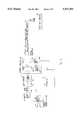
- FIG. 1is a block diagram showing a spot cure system according to the present invention
- FIG. 2is a block diagram showing in more detail the light delivery and sensing aspect of the system shown in FIG. 1;
- FIG. 3is a diagram showing the system of FIG. 1 implemented as a work station
- FIGS. 4(a) to 4(d)show the "Warm Up” and "calibration" screens for the user interface provided by the system of FIG. 1;
- FIG. 5shows the "Previous Set Up Selection” screen which is provided by the system of FIG. 1;
- FIGS. 6(a) and 6(b)show the "Main Menu” and “Set Up” screens comprising the user interface
- FIGS. 7(a) and 7(b)show the "Set Mode” and “Manual Set Up” screens comprising the user interface
- FIGS. 8(a) and 8(b)show the screen sequence produced by the system of FIG. 1 for setting the intensity level
- FIGS. 9(a) to 9(d)show the screen sequence produced by the system for setting the exposure time
- FIGS. 10(a) to 10(c)show the screen sequence produced by the system for selecting the adjustment mode
- FIGS. 11(a) to 11(e)show the screen sequence produced by the system for entering a light dosage value for the system according to the present invention
- FIGS. 12(a) to 12(e)show the screen sequence produced by the system for selecting manual control of the shutter
- FIG. 13shows the "Download Data” screen produced by the system of FIG. 1;
- FIGS. 14(a) to 14(k)shows the screen sequence produced by the system for an on-line routine to determine application specific dosage requirements
- FIG. 15is a logical flow diagram showing the method steps performed to monitor and adjust the light energy delivered by the system of FIG. 1.
- FIG. 1shows in block diagram form a system 10 according to the present invention.
- the system 10is described in the context of spot cure system for use curing photo-sensitive adhesives.
- the system 10 according to the inventionis suitable for other applications involving photo-sensitive substances which require a pre-determined amount of light energy to cause a reaction, e.g. photodynamic therapy or phototherapy.
- the spot cure system 10comprises a light source 12, an intensity level and exposure time control module 14, a light source delivery device 16, and a light sensor 18.
- a controller 20oversees and controls the operation of the system 10.
- the controller 20executes a program (e.g. firmware) which is stored in program memory 22.
- the light source 12produces light energy which is delivered by the light delivery device 14 to a work piece 24.
- the spot cure system 10provides a pre-determined amount of light energy to the work piece or object 24.
- the work piece 24includes a photochemical substance which is sensitive and reacts to the applied light energy. The reaction is controlled by the amount of the light energy which is applied.
- the controller 20controls the amount of light energy applied to the work piece 24 according to pre-selected parameters which have been inputted by a user or by an automated system. According to the invention, a consistent energy level is maintained by adjusting the exposure time and/or the intensity level to compensate for output degradation in the light source 12. As will be described in more detail below, the user can enter the desired energy level to be produced for the work object 24 and select which parameter is to be adjusted, i.e. intensity level or exposure time.
- the controller 20also includes memory 26 (e.g. RAM) which is used to store data records and other information associated with the operation of the system 10, for example, number of exposures, average exposure time, average daily run of the system 10, and a map of bulb life (intensity vs. time).
- memory 26e.g. RAM
- the system 10can include a scanner 28, e.g. a bar-code scanner, which scans or reads a bar-code identifier 30 located on the work piece 24 as shown in FIG. 1.
- the bar code scanner 28couples to the controller 20 in known manner. When the scanner 28 detects the bar code identifier 30, an ASCII character string is produced and fed to the controller 20.
- the controller 20can then generate a data record for the work piece 24 using the ASCII code as an index and comprising the exposure information, e.g. intensity level, exposure time.
- the data recordsare stored in memory 26 and can be downloaded through a communications interface 32.
- the communication interface 32can comprise a conventional serial port, e.g. RS-232 interface, which connects the controller 20 to an external printer 34 or a personal computer 36.
- the system 10includes a user interface 38 comprising a display device 40 (e.g. a Liquid Crystal Display or LCD) and an input device 42 (e.g. keypad).
- the display 40comprises a 2-line by 40-character LCD which is coupled to the controller 20 in known manner.
- the input device 42comprises a five key pad which is mapped to the bottom line of the display 40 as "soft" keys.
- "soft" keysare context-dependent and can be integrated into a "user friendly” interface.
- the user interface 38according to the present invention is described in more detail below with reference to FIGS. 5 to 14.
- the system 10also includes a PLC (Programmable Logic Control) interface 44 which allows the system 10 to be operated in a semi-automated or automated mode.
- the PLC interface 44couples the controller 20 to a program logic control 46 which in turn is programmed to control a conveyor 48.
- the conveyor 48carries work pieces 24 from station to station in an assembly line, for example, and one of the stations comprises the system 10.
- the system 10can be operate in an automated mode under the control of the PLC 46.
- the PLC 46controls operation of the system 10 by issuing commands and status requests to the controller 20 through the PLC interface 44.
- the nature of the interface and command interface between the PLC 46 and controller 20is dependent on the operational parameters of the automated assembly line and will be within the understanding of one skilled in the art. For example, the maximum exposure time or dwell time, minimum intensity level and energy dosage can be downloaded by the PLC 46 and the controller 20 will issue a dwell time update command when the exposure time is increased.
- the system 10 according to the inventioncan also be operated in a manual mode.
- the system 10is configured by a user to run as a "stand-alone" system, i.e. without the PLC 46.
- each exposure cyclei.e. curing cycle
- the external signalcan comprise an electronic signal which is generated by a switch activated by the operator.
- FIG. 2shows in more detail the intensity monitoring and control portions of the system 10 according to the invention.
- Like reference numbers in FIGS. 1 to 3refer to like elements.
- the intensity control module 12comprises a dimmer assembly 52 and a shutter 54.
- the dimmer assembly 52comprises an adjustable dimmer 56 which is coupled to an output port the controller 20 through an actuator, for example, a stepper motor 58 as will be within the understanding of one skilled in the art.
- the shutter 54is also coupled to an output port on the controller 20 through an actuator, for example a solenoid 60.
- the controller 20uses the dimmer assembly 52 to control the intensity level of the light delivered to the work piece 24 and the shutter 54 to control the time the work object 24 is exposed by the light emitted by the source 12 through the dimmer 56.
- the light output from the shutter 54 and dimmer 56are coupled to the light delivery device 16 through an optical connector 57.
- the optical connector 57is selected according to the type of light delivery device 16.
- the light delivery device 16comprises a fiber optic cable or a liquid light guide.
- the delivery device 16can be maneuvered around the work piece 24, either manually or by machine, e.g. a robotic arm.
- the fiber optic cable or liquid light guidecan be eliminated, for example, where the light source 12 comprises a LED array which illuminates an area.
- the light source 12comprises a light chamber 62 which houses a light bulb 64.
- the light bulb 64can comprise known devices such as an arc source (e.g. mercury, xenon, or mercury/xenon), an incandescent source (e.g. quartz halogen), an "electrode-less” source (e.g. microwave source), or a solid state light source, e.g. a single light emitting diode (LED) or a multiple array device.
- the type of light bulb 64 which is selecteddepends on the characteristics of the photo-reactive substance on the work object 24, e.g. wavelength of the bulb 64, and the operational parameters for the system 10, e.g. maximum intensity level.
- the light chamber 62couples the bulb 64 to the intensity control module 12 (i.e. dimmer 56 and shutter 54) and also to the light sensor module 18.
- the light sensor module 18 in the preferred embodimentcomprises a radiometer.
- the radiometeris a precision light measuring instrument.
- the radiometer 18 as shown in FIG. 2is coupled to the controller 20 and includes two photodiodes 66 and 63.
- the first photodiode 66is optically coupled to the light chamber 62.
- the controller 20uses the output from the first photodiode 66 to monitor the intensity level of the light output from the bulb 64.
- the second photodiode 68is optically coupled to an external calibration port 70.
- the calibration port 70is used to measure the light delivered to the work object 24 at the emitting end of the fiber optic cable or liquid light-guide 16.
- the controller 20can use the light measured by the second photodiode 68 and the first photodiode 66 to detect degradation in the light delivery capability of the fiber optic cable or light guide 16.
- the controller 20measures the current intensity level of the bulb 64. If the desired light energy amount cannot be maintained by the current intensity level, the controller 24 will make an adjustment in the intensity level output by opening the dimmer 56). The controller 20 can also compensate for the degradation of the bulb 24 by increasing the exposure time by opening the shutter 54 for a longer time. Both of these adjustment modes are described below with reference to FIG. 10. The operator selects the adjustment mode, i.e. exposure time adjustment or intensity adjustment as will also be described below with reference to FIGS. 10(a) to 10(c).
- FIG. 3shows in diagrammatic form an implementation of the system 10 of FIG. 1 as an integrated work station 72.
- the work station 72comprises a cabinet 74 which houses the components of the system 10.
- the display 40 and key pad 42are mounted on the front panel of the cabinet 74.
- the front panel of the cabinet 74includes the fiber optic connector port 57 and the external calibration port 70.
- the front panel of the a cabinetalso includes a power on/off switch 76.
- the cabinet 74also includes appropriate connectors for the communication interface 32 and the PLC interface 44.
- the radiometer 18is packaged as a detachable module 80.
- the detachable designallows the radiometer 80 to be easily removed for calibration. Since it is desirable to calibrate the radiometer 80 according to industry standards, e.g. NIST (National Institute of Standards Technology) parameters, calibration will typically be off-site and thus it is convenient and useful to remove the module 80 for testing and plug a spare radiometer (not shown) which has been calibrated.
- industry standardse.g. NIST (National Institute of Standards Technology) parameters
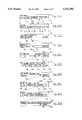
- FIG. 4(a)shows a "Warm Up" screen 100 which is produced by the controller 20 when the system 10 is being initialized, e.g. when the power if first turned on.
- the screens produced by the system 10 according to the inventioncomprise a first line 102 and a second line 104, which correspond to the two lines on the LCD 40 (FIGS. 1 and 3).
- the first line 102is reserved for prompt messages or status messages.
- the second line 104is used to display the soft key functions which have been assigned to the corresponding soft keys in the key pad 42.
- the functions of the keys in the pad 42change depending on the screen, i.e. context, and the function associated with a softkey is displayed on the second line in a portion above the key. Pressing a key causes the controller 20 to execute the function currently associated with that key in the screen.
- a portion of the second line 104can be made available to display a prompt message which overflows the first line 102, e.g. more than 40 characters.
- the controller 20executes an initialization routine.
- the initialization routineinvolves initializing the peripherals coupled to the controller 10, e.g. the display 40, communications interface 32 and the PLC interface 44, performing a "RAM" or memory check and other self diagnostics.
- the controller 20sets the dimmer 56 to a default position of wide open, i.e. maximum intensity.
- a DONE softkey 108is activated on the display 40 and key pad 42.
- the controller 20In response to the user pressing the DONE key 108, the controller 20 displays a "Calibrate" prompt screen 110 which comprises a CONTINUE softkey 112 as shown in FIG. 4(b).
- the system 10must obtain an intensity reading from the end of the fiber optic cable or liquid light guide 16 before it will proceed further.
- the controller 20displays another screen 114 when the CONTINUE softkey 112 is pressed.
- the screen 114comprises a prompt 116 on the top line 102 and two softkeys GO 118 and RETURN 120.
- the prompt 116notifies the user to insert the emitting end of the fiber optic cable 16 into the calibration port 70 (FIGS. 1 and 3) and then press the GO key 118.
- the controller 20determines the intensity level (via the photodiode 68 in the radiometer 18) and the measured intensity level is displayed on the top line of another screen 122 as shown in FIG. 4(d).
- the screen 112includes a CONTINUE softkey 124 and a RETURN softkey 126. Pressing the RETURN key 126, returns the user to the CALIBRATE screen 110.
- the controller 20checks if a previous set up has been entered. If yes, the controller 20 displays a screen 128 as shown in FIG. 5. The screen 128 includes a prompt on the top line as shown and two softkeys YES 130 and NO 132. If YES 130 is pressed, the controller 20 retrieves the previously stored set up. If NO 132 is pressed, the controller 20 displays a "MAIN MENU" screen 134 as shown in FIG. 6(a).
- the Main Menu screen 134includes a SETUP softkey 136, a RUN softkey 138, a CALIBRATE softkey 140, a STATUS softkey 142 and a DATA softkey 144.
- the RUN key 138is used to control the "manual" mode of operation and is described in more detail below with reference to FIGS. 12(a) to 12(e).
- the CALIBRATE key 140allows the user to initiate a calibration and the controller 20 produces a sequence of screens as shown in FIGS. 4(b) to 4(d) described above.
- the STATUS key 142produces a status screen which displays the current intensity level, exposure time, the lamp hours, the energy level, and the mode, i.e. manual or automated.
- the DATA key 144is used to access a PC/Printer download screen which is described in more detail with reference to FIG. 13.
- the controller 20displays a SET UP sub-menu screen 146 as shown in FIG. 6(b).
- the sub-menu screen 146includes another five softkeys which provide the user with various set up functions.
- the softkeyscomprise a LANGUAGE softkey 148, a DOSAGE softkey 150, a MODE softkey 152, a CONTROL softkey 154 and a RETURN softkey 156.
- Pressing the LANGUAGE key 154causes the controller 20 to display a screen (not shown) which allows the user to select the Language, e.g. English, French, German or Spanish.
- Languagee.g. English, French, German or Spanish.
- the DOSAGE softkey 150is used by the operator to access an on-line routine which helps the operator determine the dosage for a specific application. The operation of the DOSAGE softkey 150 is described in more detail below with reference to FIGS. 14(a) to (k).
- the MODE softkey 152allows the user to select the "Manual" or "Automated” mode of operation.
- a curing or light cycleis initiated by an external signal source, such as a foot pedal coupled to the manual input port 50, or a user entry on the key pad 42.
- an external signal sourcesuch as a foot pedal coupled to the manual input port 50, or a user entry on the key pad 42.
- a curing or light cycleis initiated by another external signal source, for example, the output from the PLC 46. It will be appreciated that in both Manual and Automated modes, the curing cycle is initiated by an external signal, and the difference lies in the source of the external signal and the degree of the control exercised e.g. full external control in automated mode.
- the CONTROL softkey 154allows the user to select the parameter which will be adjusted in order to maintain the predetermined energy level which is delivered to the work piece 24.
- the controller 20can maintain a constant energy level by varying the exposure time or by varying the intensity level.
- the controller 20uses the shutter 54 to control the exposure time, e.g. exposure time is increased by opening the shutter 54 for a longer period.
- the controller 20operates the dimmer 56. For example, if the output from the bulb 64 has decreased, the controller 20 can increase the intensity level by further opening the dimmer 56. It will be appreciated by those skilled in the art that there are certain photo-reactive applications where a lower intensity over a longer period is useful and preferable to high intensity over a shorter period.
- pressing the RETURN key 156causes the controller 20 return to the Main Menu screen 134 shown in FIG. 6(a).
- Pressing the MODE key 152 in the Set Up screen 146causes the controller 20 to display a screen 158 as shown in FIG. 7(a).
- the screen 158comprises a prompt 160 on the top line and two softkeys MANUAL 160 and AUTOMATED 162. Pressing the MANUAL key 160 causes the controller to display a Manual Set Up screen 164 as shown in FIG. 7(b).
- the Manual Set Up screen 164comprises four softkeys: TIME 166, INTENSITY 168, DOSE 170 and RETURN 172.
- the operatoruses the TIME 166 key to enter the exposure time for the curing application, and the INTENSITY key 168 to enter the intensity level.
- the DOSE key 170is for entering the amount of energy (in milliJoules) which is required for the curing cycle.
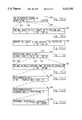
- Pressing the INTENSITY key 168causes the controller 20 to display a Set Intensity screen 174 as shown in FIG. 8(a).
- the screen 174comprises a prompt 176 on the top line and two softkeys: USE MAX 178 and SET 180.
- the prompt 176displays the current intensity level measured by the radiometer 18 and controller 20, and corresponds to the maximum intensity available, i.e. the dimmer 56 is wide open.
- To enter a value for the intensity levelthe user presses the SET key 180.
- the controller 20displays a Set Desired Intensity screen 182 as shown in FIG. 8(b).
- the Set Desired Intensity screen 182comprises a prompt 184 and five softkeys: +10000 key 186, +1000 key 188, +100 key 190, an OK key 192 and a RETURN key 194.
- the prompt 184displays the current intensity level which has been entered by the user through the softkeys 186 to 190.
- the userpushes the OK key 192 to save the intensity setting.
- the controller 20uses the intensity setting to determine the amount the dimmer 56 should be opened (or closed). Pressing the RETURN key 194 causes the controller 20 to return to the previous screen without saving the user entered intensity level.
- pressing the TIME key 166causes the controller 20 to display a Set Exposure Time screen 196 as shown in FIG. 9(a).
- the screen 196comprises a prompt on the top line and a CONTINUAL softkey 198, a SET softkey 200 and a RETURN softkey 202. Pressing the CONTINUAL key 198 causes the controller 20 to set the shutter 54 open. If the user presses the SET key 200, the controller 20 displays an Exposure Time Input screen 204 as shown in FIG. 9(b).
- the Exposure Time Input screen 204comprises a prompt 206 and five softkeys: +1 Hr key 208, +10 Mins key 210, +1 Min key 212, a SECONDS key 214 and an OK key 216.
- the operatoruses the three keys 208,210,212 to enter the exposure time which is displayed as the prompt 206. If the user wishes to enter the "seconds" portion for the exposure time, the user presses the SECONDS key 214 which causes the controller 20 to display an input screen 218 as shown in FIG. 9(c). To save the exposure time entry, the screen 218 includes an OK key 220. Pressing the OK key 220 causes the controller 20 to save the time entered by user and vary the operating parameters for the shutter 56 accordingly.
- the controller 20displays a screen 222 as shown in FIG. 9(d).
- the screen 222shows the current settings (on the top line) which have been entered and provides an OK softkey 224 for verifying the settings or a RESET key 226 for clearing the settings.
- pressing the DOSE key 170causes the controller 20 to display a Dosage input screen 240 as shown in FIG. 11(a).
- the screen 240comprises a prompt 242 which shows the desired dosage currently entered.
- the screen 240also includes three softkeys: +10000 key 244, +1000 key 246, and +100 key 248 for entering the dosage value, and an OK softkey 250.
- Pressing the OK key 250causes the controller 20 to display a screen 252 for setting the maximum allowable exposure time for the dosage value entered in the previous screen 240.
- the userenters the maximum exposure time using screens 254 and 256 as shown in FIGS. 11(c) and 11(d) respectively.
- the userverifies the entered dosage value and maximum exposure time using screen 258 shown in FIG. 11(e).
- Pressing the CONTROL key 154causes the controller 20 to display a screen 228 as shown in FIG. 10(a).
- the screen 228 shown in FIG. 10(a)comprises an INTENSITY softkey 230, a TIME softkey 232 and a RETURN softkey 234. Pressing the TIME key 232 causes the controller 20 to display a screen 236 as shown in FIG. 10(b) which allows the user select the time adjustment mode.
- the controller 20increases the exposure time up to a pre-determined maximum value (via the shutter 56) as the output of the bulb 64 degrades.
- Pressing the INTENSITY key 230causes the controller 20 to display a screen 238 as shown in FIG. 10(c).
- the screen 238allows the user to select the intensity adjustment mode, i.e. the controller 20 increases the opening of the dimmer 54 to compensate for degradation in the bulb 64 and maintain a consistent energy output level to the work piece 24.
- the usercan start the system 10 by pressing the RUN key 138 in the Main Menu 134 shown in FIG. 6(a). Pressing the RUN key 138 causes the controller 20 to display a screen 260 as shown in FIG. 12(a).
- the screen 260allows the user to select the source of the manual input signal for initiating the curing cycle.
- the screen 260includes a softkey 262 for selecting a PEDAL input (coupled to the manual input port 50--FIG. 1) and a softkey 264 for selecting a key pad for the trigger input. Pressing the PEDAL key 262 causes the controller 20 to display a verification screen 266 as shown in FIG.
- the controller 20displays a screen 268 as shown in FIG. 12(c). If the user selects the key pad 42 as the manual input, the controller 20 displays a screen 270 as shown in FIG. 12(d) and generates a screen 272 as shown in FIG. 12(e) when the user verifies the selection.
- the userpresses the DATA key 144 in the Main Menu 134. Pressing the DATA key 144 causes the controller 20 to display a Download Control screen 274 as shown in FIG. 13.
- the Download Control screen 274provides the user with a PC softkey 276 for downloading the data to another computer 36 (FIG. 1) or a PRINTER softkey 278 for "dumping" the data to the printer 34 coupled to the communications interface 32.
- FIGS. 14(a) to 14(k)show the screen sequence produced by the system 10 for the on-line routine which is used to determine application specific dosage requirements. For example, there may be instances where the operator does not know the dosage for a particular type of adhesive or application. By following the prompts and steps in the screens as shown in FIGS. 14(a) to (k), the system 10 helps the operator determine the dosage for a particular application.
- the on-line routine shown in FIG. 14is accessed by pressing the DOSAGE softkey 150 in the Set Up screen 146 shown in FIG. 6(b).
- FIG. 15provides a logical flow diagram for the steps executed by the controller 20 to maintain a consistent energy output level according to the pre-determined set up and operating parameters (e.g. maximum exposure time and intensity adjustment mode) and the current intensity output level of the light source.
- the pre-determined set up and operating parameterse.g. maximum exposure time and intensity adjustment mode
Landscapes
- Health & Medical Sciences (AREA)
- Biomedical Technology (AREA)
- Life Sciences & Earth Sciences (AREA)
- Engineering & Computer Science (AREA)
- Nuclear Medicine, Radiotherapy & Molecular Imaging (AREA)
- Pathology (AREA)
- Biophysics (AREA)
- Radiology & Medical Imaging (AREA)
- Animal Behavior & Ethology (AREA)
- General Health & Medical Sciences (AREA)
- Public Health (AREA)
- Veterinary Medicine (AREA)
- Circuit Arrangement For Electric Light Sources In General (AREA)
Abstract
Description
Claims (25)
Priority Applications (1)
| Application Number | Priority Date | Filing Date | Title |
|---|---|---|---|
| US08/235,621US5521392A (en) | 1994-04-29 | 1994-04-29 | Light cure system with closed loop control and work piece recording |
Applications Claiming Priority (1)
| Application Number | Priority Date | Filing Date | Title |
|---|---|---|---|
| US08/235,621US5521392A (en) | 1994-04-29 | 1994-04-29 | Light cure system with closed loop control and work piece recording |
Publications (1)
| Publication Number | Publication Date |
|---|---|
| US5521392Atrue US5521392A (en) | 1996-05-28 |
Family
ID=22886287
Family Applications (1)
| Application Number | Title | Priority Date | Filing Date |
|---|---|---|---|
| US08/235,621Expired - LifetimeUS5521392A (en) | 1994-04-29 | 1994-04-29 | Light cure system with closed loop control and work piece recording |
Country Status (1)
| Country | Link |
|---|---|
| US (1) | US5521392A (en) |
Cited By (104)
| Publication number | Priority date | Publication date | Assignee | Title |
|---|---|---|---|---|
| US5742718A (en)* | 1996-08-13 | 1998-04-21 | Eclipse Surgical Technologies, Inc. | Proprietary fiber connector and electronic security system |
| US5759200A (en)* | 1996-09-04 | 1998-06-02 | Azar; Zion | Method of selective photothermolysis |
| US5975895A (en)* | 1997-11-12 | 1999-11-02 | Coltene/Whaledent | Strobe light curing apparatus and method |
| US6124599A (en)* | 1996-06-12 | 2000-09-26 | Canon Kabushiki Kaisha | Electron beam exposure system and method of manufacturing devices using the same |
| US6200134B1 (en) | 1998-01-20 | 2001-03-13 | Kerr Corporation | Apparatus and method for curing materials with radiation |
| US6214034B1 (en) | 1996-09-04 | 2001-04-10 | Radiancy, Inc. | Method of selective photothermolysis |
| WO2001045471A1 (en) | 1999-12-14 | 2001-06-21 | Efos Inc. | Smart lamp |
| US6331111B1 (en) | 1999-09-24 | 2001-12-18 | Cao Group, Inc. | Curing light system useful for curing light activated composite materials |
| US6350071B1 (en) | 2000-06-21 | 2002-02-26 | Intermec Ip Corp. | On demand printer apparatus and method with integrated UV curing |
| WO2001097912A3 (en)* | 2000-06-21 | 2002-06-20 | Raymond A Hartman | Targeted uv phototherapy apparatus and method |
| US20020163317A1 (en)* | 1999-09-24 | 2002-11-07 | Densen Cao | Curing light |
| US20020168608A1 (en)* | 1999-09-24 | 2002-11-14 | Densen Cao | Curing light |
| US20020172914A1 (en)* | 1999-09-24 | 2002-11-21 | Densen Cao | Curing light |
| US20020177099A1 (en)* | 1999-09-24 | 2002-11-28 | Cao Group, Inc. | Light for activating light-activated materials, the light including a plurality of individual chips and providing a particular spectral profile |
| US20020182561A1 (en)* | 1999-09-24 | 2002-12-05 | Densen Cao | Curing light |
| US20020181947A1 (en)* | 1999-09-24 | 2002-12-05 | Densen Cao | Method for curing composite materials |
| US6574501B2 (en) | 1998-07-13 | 2003-06-03 | Childrens Hospital Los Angeles | Assessing blood brain barrier dynamics or identifying or measuring selected substances or toxins in a subject by analyzing Raman spectrum signals of selected regions in the eye |
| US20030133298A1 (en)* | 1999-09-24 | 2003-07-17 | Densen Cao | Light for use in activating light-activated materials, the light having a plurality of chips mounted in a gross well of a heat sink, and a dome covering the chips |
| US20030142413A1 (en)* | 2002-01-11 | 2003-07-31 | Ultradent Products, Inc. | Cone-shaped lens having increased forward light intensity and kits incorporating such lenses |
| US20030148242A1 (en)* | 2002-02-05 | 2003-08-07 | Fischer Dan E. | Lightweight hand held dental curing device |
| US20030165398A1 (en)* | 1999-06-03 | 2003-09-04 | Waldo Jeffrey M. | Apparatus, systems and methods for processing and treating a biological fluid with light |
| US20030230377A1 (en)* | 2002-06-14 | 2003-12-18 | Turvey Robert R. | Apparatus and method for automated splicing of closer tape |
| US20040012665A1 (en)* | 2000-08-02 | 2004-01-22 | Taylor Jeffrey F. | Methods of thermal transfer printing and thermal transfer printers |
| US20040019283A1 (en)* | 1998-07-13 | 2004-01-29 | Lambert James L. | Assessing blood brain barrier dynamics or identifying or measuring selected substances, including ethanol or toxins, in a subject by analyzing Raman spectrum signals |
| US6716252B2 (en) | 2000-06-30 | 2004-04-06 | Wit Ip Corporation | Prostatic stent with localized tissue engaging anchoring means and methods for inhibiting obstruction of the prostatic urethra |
| US6719559B2 (en) | 1999-09-24 | 2004-04-13 | Densen Cao | Curing light |
| US6719558B2 (en) | 1999-09-24 | 2004-04-13 | Densen Cao | Curing light |
| US20040094727A1 (en)* | 2001-03-01 | 2004-05-20 | Mark Holmes | Integral filter support and shutter stop for uv curing system |
| US20040101802A1 (en)* | 2002-11-21 | 2004-05-27 | Scott Robert R. | Wide bandwidth led curing light |
| US20040121280A1 (en)* | 2002-12-18 | 2004-06-24 | Fischer Dan E. | Light curing device with detachable power supply |
| US20040121281A1 (en)* | 2002-12-18 | 2004-06-24 | Fischer Dan E. | Cooling system for hand-held curing light |
| US6755649B2 (en) | 1999-09-24 | 2004-06-29 | Cao Group, Inc. | Curing light |
| US6755648B2 (en) | 1999-09-24 | 2004-06-29 | Cao Group, Inc. | Curing light |
| US20040127778A1 (en)* | 2001-01-09 | 2004-07-01 | Lambert James L. | Identifying or measuring selected substances or toxins in a subject using resonant raman signals |
| US6780010B2 (en) | 1999-09-24 | 2004-08-24 | Cao Group, Inc. | Curing light |
| US6783810B2 (en) | 2000-03-15 | 2004-08-31 | Dentsply Research & Development Corp. | Reducing polymerization stress by controlled segmental curing |
| US6799967B2 (en) | 2001-07-10 | 2004-10-05 | Cao Group, Inc. | Light for use in activating light-activated materials, the light having a plurality of light emitting single chip arrays |
| US20040214131A1 (en)* | 2003-04-25 | 2004-10-28 | Ultradent Products, Inc., | Spot curing lens used to spot cure a dental appliance adhesive and systems and methods employing such lenses |
| US6853394B2 (en) | 2000-08-02 | 2005-02-08 | Sony Chemicals Corporation Of America | Radiation-curable thermal printing ink and ink ribbons and methods of making, using and printing using the same |
| US20050042570A1 (en)* | 2003-08-20 | 2005-02-24 | Fischer Dan E. | Dental curing light adapted to emit light at a desired angle |
| US6910886B2 (en) | 1999-09-24 | 2005-06-28 | Cao Group, Inc. | Curing light |
| US20050142514A1 (en)* | 2003-12-30 | 2005-06-30 | Scott Robert R. | Dental curing device having a heat sink for dissipating heat |
| US20050167580A1 (en)* | 2004-02-02 | 2005-08-04 | Kurt Scott | Accelerated weathering test apparatus with full spectrum calibration, monitoring and control |
| US6929472B2 (en) | 1999-09-24 | 2005-08-16 | Cao Group, Inc. | Curing light |
| US20050231983A1 (en)* | 2002-08-23 | 2005-10-20 | Dahm Jonathan S | Method and apparatus for using light emitting diodes |
| US6971876B2 (en) | 1999-09-24 | 2005-12-06 | Cao Group, Inc. | Curing light |
| US6971875B2 (en) | 1999-09-24 | 2005-12-06 | Cao Group, Inc. | Dental curing light |
| US6979193B2 (en) | 1999-09-24 | 2005-12-27 | Cao Group, Inc. | Curing light |
| US6981867B2 (en) | 1999-09-24 | 2006-01-03 | Cao Group, Inc. | Curing light |
| US6988891B2 (en) | 1999-09-24 | 2006-01-24 | Cao Group, Inc. | Curing light |
| US6988890B2 (en) | 1999-09-24 | 2006-01-24 | Cao Group, Inc. | Curing light |
| US20060088797A1 (en)* | 2004-10-26 | 2006-04-27 | Scott Robert R | Heat sink for dental curing light comprising a plurality of different materials |
| US7066732B2 (en) | 1999-09-24 | 2006-06-27 | Cao Group, Inc. | Method for curing light-curable materials |
| US20060139722A1 (en)* | 2004-12-23 | 2006-06-29 | Roy Kayser | Method of calibrating light delivery systems, light delivery systems and radiometer for use therewith |
| US7074040B2 (en) | 2004-03-30 | 2006-07-11 | Ultradent Products, Inc. | Ball lens for use with a dental curing light |
| US7098465B1 (en)* | 2004-06-25 | 2006-08-29 | Henkel Corporation | Integrated inert gas for electromagnetic energy spot curing system |
| US7106523B2 (en) | 2002-01-11 | 2006-09-12 | Ultradent Products, Inc. | Optical lens used to focus led light |
| US7108504B2 (en) | 2001-07-10 | 2006-09-19 | Cao Group, Inc. | Light for use in activating light-activated materials, the light having insulators and an air jacket |
| USD529613S1 (en) | 2003-02-18 | 2006-10-03 | Ultradent Products, Inc. | Dental illumination device |
| USD530013S1 (en) | 2003-02-18 | 2006-10-10 | Ultradent Products, Inc. | Dental illumination device |
| US20060269897A1 (en)* | 2005-05-27 | 2006-11-30 | Gill Owen J | Curing light instrument |
| US7144250B2 (en) | 2003-12-17 | 2006-12-05 | Ultradent Products, Inc. | Rechargeable dental curing light |
| US7148498B1 (en)* | 2004-06-25 | 2006-12-12 | Henkel Corporation | Externally controlled electromagnetic energy spot curing system |
| US20070020578A1 (en)* | 2005-07-19 | 2007-01-25 | Scott Robert R | Dental curing light having a short wavelength LED and a fluorescing lens for converting wavelength light to curing wavelengths and related method |
| US20070037113A1 (en)* | 2005-08-10 | 2007-02-15 | Scott Robert R | Dental curing light including a light integrator for providing substantially equal distribution of each emitted wavelength |
| US7182597B2 (en) | 2002-08-08 | 2007-02-27 | Kerr Corporation | Curing light instrument |
| US20070128577A1 (en)* | 2005-12-05 | 2007-06-07 | Ultradent Products, Inc. | Dental curing lights including a capacitor power source |
| US20070185553A1 (en)* | 2006-02-06 | 2007-08-09 | John Kennedy | Therapy device and system and method for reducing harmful exposure to electromagnetic radiation |
| US20070206901A1 (en)* | 2006-03-02 | 2007-09-06 | Bonitatibus Michael H | Sunlight simulator apparatus |
| US7320593B2 (en) | 2000-03-08 | 2008-01-22 | Tir Systems Ltd. | Light emitting diode light source for curing dental composites |
| US20080026339A1 (en)* | 2006-07-31 | 2008-01-31 | Ivoclar Vivadent Ag | Hand-held light curing device |
| US20080023625A1 (en)* | 2006-07-31 | 2008-01-31 | Ivoclar Vivadent Ag | Light Measurement apparatus |
| US20080177359A1 (en)* | 2002-05-03 | 2008-07-24 | Advanced Light Technology, Llc. | Differential photochemical and photomechanical processing |
| USD575407S1 (en) | 2005-10-26 | 2008-08-19 | Pharos Life Corporation | Phototherapy device |
| US20080197300A1 (en)* | 2004-12-23 | 2008-08-21 | Roy Kayser | Method of calibrating light delivery systems, light delivery systems and radiometer for use therewith |
| US20080208294A1 (en)* | 2003-02-28 | 2008-08-28 | Advanced Light Technology, Llc | Disinfection, destruction of neoplastic growth, and sterilization by differential absorption of electromagnetic energy |
| US20080273329A1 (en)* | 2004-06-15 | 2008-11-06 | Belek Ronald E | High Power Led Electro-Optic Assembly |
| US20080274436A1 (en)* | 2007-05-04 | 2008-11-06 | Den-Mat Corporation | Optically regulated dental light unit |
| US20090130328A1 (en)* | 2004-11-01 | 2009-05-21 | Uview Ultraviolet Systems Inc. | Apparatus and method for curing surface coated materials |
| US20090159779A1 (en)* | 2007-12-24 | 2009-06-25 | Hon Hai Precision Industry Co., Ltd. | Light curing apparatus |
| US20090159442A1 (en)* | 2007-12-20 | 2009-06-25 | Gordon Bruce Collier | Formation of immobilized biological layers for sensing |
| US7645056B1 (en) | 1997-09-25 | 2010-01-12 | Koninklijke Philips Electronics N V | Optical irradiation device having LED and heat pipe |
| US20100016849A1 (en)* | 2008-07-16 | 2010-01-21 | Avner Rosenberg | Rf electrode for aesthetic and body shaping devices and method of using same |
| US20100016761A1 (en)* | 2008-07-16 | 2010-01-21 | Avner Rosenberg | Applicator for skin treatement with automatic regulation of skin protrusion magnitude |
| US20100154244A1 (en)* | 2008-12-19 | 2010-06-24 | Exfo Photonic Solutions Inc. | System, Method, and Adjustable Lamp Head Assembly, for Ultra-Fast UV Curing |
| US20100196214A1 (en)* | 2009-02-05 | 2010-08-05 | Eugene Graff | Air purifying luminaire |
| US20100255120A1 (en)* | 2007-12-20 | 2010-10-07 | Gordon Bruce Collier | Compositions for forming immobilized biological layers for sensing |
| US7837091B2 (en) | 2005-05-20 | 2010-11-23 | Laserscope | Laser system and delivery device operation logging method and kit |
| US20110015549A1 (en)* | 2005-01-13 | 2011-01-20 | Shimon Eckhouse | Method and apparatus for treating a diseased nail |
| US20110040295A1 (en)* | 2003-02-28 | 2011-02-17 | Photometics, Inc. | Cancer treatment using selective photo-apoptosis |
| US20110144410A1 (en)* | 2004-08-06 | 2011-06-16 | John Kennedy | Therapy Device and Related Accessories, Compositions, and Treatment Methods |
| US8047686B2 (en) | 2006-09-01 | 2011-11-01 | Dahm Jonathan S | Multiple light-emitting element heat pipe assembly |
| US8771263B2 (en) | 2008-01-24 | 2014-07-08 | Syneron Medical Ltd | Device, apparatus, and method of adipose tissue treatment |
| US8778003B2 (en) | 2008-09-21 | 2014-07-15 | Syneron Medical Ltd | Method and apparatus for personal skin treatment |
| US8900231B2 (en) | 2004-09-01 | 2014-12-02 | Syneron Medical Ltd | Method and system for invasive skin treatment |
| US9066777B2 (en) | 2009-04-02 | 2015-06-30 | Kerr Corporation | Curing light device |
| US9072572B2 (en) | 2009-04-02 | 2015-07-07 | Kerr Corporation | Dental light device |
| US9084587B2 (en) | 2009-12-06 | 2015-07-21 | Syneron Medical Ltd | Method and apparatus for personal skin treatment |
| US9278230B2 (en) | 2009-02-25 | 2016-03-08 | Syneron Medical Ltd | Electrical skin rejuvenation |
| US9301588B2 (en) | 2008-01-17 | 2016-04-05 | Syneron Medical Ltd | Hair removal apparatus for personal use and the method of using same |
| US9504826B2 (en) | 2009-02-18 | 2016-11-29 | Syneron Medical Ltd | Skin treatment apparatus for personal use and method for using same |
| US9726435B2 (en) | 2002-07-25 | 2017-08-08 | Jonathan S. Dahm | Method and apparatus for using light emitting diodes for curing |
| KR20190033478A (en)* | 2016-06-17 | 2019-03-29 | 쏘흐본느 유니베흐시테 | Apparatus and related method for illuminating an object with controlled luminous intensity |
| US11116616B2 (en) | 2014-09-17 | 2021-09-14 | Garrison Dental Solutions, L.L.C. | Dental curing light |
Citations (23)
| Publication number | Priority date | Publication date | Assignee | Title |
|---|---|---|---|---|
| US3614682A (en)* | 1970-06-22 | 1971-10-19 | Firestone Tire & Rubber Co | Digital computer control of polymerization process |
| US3679903A (en)* | 1970-10-30 | 1972-07-25 | Western Electric Co | Apparatus for controlling the intensity of radiant energy on a strip |
| US3705787A (en)* | 1969-07-21 | 1972-12-12 | Snam Progetti | Method for regulating the temperature and the conversion in a polymerization reactor and apparatus suitable to realize the same |
| US4024428A (en)* | 1975-05-19 | 1977-05-17 | Optical Associates, Incorporated | Radiation-sensitive control circuit for driving lamp at various power levels |
| US4032817A (en)* | 1974-12-12 | 1977-06-28 | Harris Corporation | Wide range power control for electric discharge lamp and press using the same |
| US4033263A (en)* | 1974-12-12 | 1977-07-05 | Harris Corporation | Wide range power control for electric discharge lamp and press using the same |
| USRE30571E (en)* | 1979-04-18 | 1981-04-07 | Optical Associates, Inc. | Radiation-sensitive control circuit for driving lamp at various power levels |
| US4396872A (en)* | 1981-03-30 | 1983-08-02 | General Mills, Inc. | Ballast circuit and method for optimizing the operation of high intensity discharge lamps in the growing of plants |
| US4399100A (en)* | 1980-12-29 | 1983-08-16 | Lockheed Corporation | Automatic process control system and method for curing polymeric materials |
| US4417179A (en)* | 1981-05-08 | 1983-11-22 | Hitachi, Ltd. | Light quantity control device |
| US4636071A (en)* | 1985-11-05 | 1987-01-13 | Northern Telecom Limited | Method and apparatus for measuring single mode fiber mode field radius |
| US4641033A (en)* | 1984-12-19 | 1987-02-03 | Fusion Systems Corporation | Apparatus and method preventing radiation induced degradation of optical elements |
| US4665627A (en)* | 1985-11-01 | 1987-05-19 | Research, Incorporated | Dry film curing machine with ultraviolet lamp controls |
| US4716097A (en)* | 1986-02-03 | 1987-12-29 | E. I. Du Pont De Nemours And Company | Increased photopolymer photospeed employing yellow light preexposure |
| US4742131A (en)* | 1985-12-27 | 1988-05-03 | Mitsui Toatsu Chemicals, Incorporated | Method of controlling polymerization temperature |
| US4819177A (en)* | 1987-06-19 | 1989-04-04 | Systran Corporation | Method for curing rubber articles |
| US4819842A (en)* | 1987-09-03 | 1989-04-11 | Dymax Corporation | Radiation supply and adhesive dispensing system |
| US4842404A (en)* | 1988-01-13 | 1989-06-27 | Ilc Technology, Inc. | Dual detector laser beam power monitor |
| US4930504A (en)* | 1987-11-13 | 1990-06-05 | Diamantopoulos Costas A | Device for biostimulation of tissue and method for treatment of tissue |
| US5137800A (en)* | 1989-02-24 | 1992-08-11 | Stereographics Limited Partnership | Production of three dimensional bodies by photopolymerization |
| US5139331A (en)* | 1991-04-29 | 1992-08-18 | John Gentile | Radiometer including means for alternately measuring both power and energy with one pyroelectric detector |
| US5395591A (en)* | 1988-05-02 | 1995-03-07 | Zimlich, Jr.; William C. | Apparatus of irradiating biological specimens |
| US5418369A (en)* | 1993-03-12 | 1995-05-23 | At&T Corp. | System for continuously monitoring curing energy levels within a curing unit |
- 1994
- 1994-04-29USUS08/235,621patent/US5521392A/ennot_activeExpired - Lifetime
Patent Citations (24)
| Publication number | Priority date | Publication date | Assignee | Title |
|---|---|---|---|---|
| US3705787A (en)* | 1969-07-21 | 1972-12-12 | Snam Progetti | Method for regulating the temperature and the conversion in a polymerization reactor and apparatus suitable to realize the same |
| US3614682A (en)* | 1970-06-22 | 1971-10-19 | Firestone Tire & Rubber Co | Digital computer control of polymerization process |
| US3679903A (en)* | 1970-10-30 | 1972-07-25 | Western Electric Co | Apparatus for controlling the intensity of radiant energy on a strip |
| US4032817A (en)* | 1974-12-12 | 1977-06-28 | Harris Corporation | Wide range power control for electric discharge lamp and press using the same |
| US4033263A (en)* | 1974-12-12 | 1977-07-05 | Harris Corporation | Wide range power control for electric discharge lamp and press using the same |
| US4024428A (en)* | 1975-05-19 | 1977-05-17 | Optical Associates, Incorporated | Radiation-sensitive control circuit for driving lamp at various power levels |
| US4117375A (en)* | 1975-05-19 | 1978-09-26 | Optical Associates, Incorporated | Exposure system |
| USRE30571E (en)* | 1979-04-18 | 1981-04-07 | Optical Associates, Inc. | Radiation-sensitive control circuit for driving lamp at various power levels |
| US4399100A (en)* | 1980-12-29 | 1983-08-16 | Lockheed Corporation | Automatic process control system and method for curing polymeric materials |
| US4396872A (en)* | 1981-03-30 | 1983-08-02 | General Mills, Inc. | Ballast circuit and method for optimizing the operation of high intensity discharge lamps in the growing of plants |
| US4417179A (en)* | 1981-05-08 | 1983-11-22 | Hitachi, Ltd. | Light quantity control device |
| US4641033A (en)* | 1984-12-19 | 1987-02-03 | Fusion Systems Corporation | Apparatus and method preventing radiation induced degradation of optical elements |
| US4665627A (en)* | 1985-11-01 | 1987-05-19 | Research, Incorporated | Dry film curing machine with ultraviolet lamp controls |
| US4636071A (en)* | 1985-11-05 | 1987-01-13 | Northern Telecom Limited | Method and apparatus for measuring single mode fiber mode field radius |
| US4742131A (en)* | 1985-12-27 | 1988-05-03 | Mitsui Toatsu Chemicals, Incorporated | Method of controlling polymerization temperature |
| US4716097A (en)* | 1986-02-03 | 1987-12-29 | E. I. Du Pont De Nemours And Company | Increased photopolymer photospeed employing yellow light preexposure |
| US4819177A (en)* | 1987-06-19 | 1989-04-04 | Systran Corporation | Method for curing rubber articles |
| US4819842A (en)* | 1987-09-03 | 1989-04-11 | Dymax Corporation | Radiation supply and adhesive dispensing system |
| US4930504A (en)* | 1987-11-13 | 1990-06-05 | Diamantopoulos Costas A | Device for biostimulation of tissue and method for treatment of tissue |
| US4842404A (en)* | 1988-01-13 | 1989-06-27 | Ilc Technology, Inc. | Dual detector laser beam power monitor |
| US5395591A (en)* | 1988-05-02 | 1995-03-07 | Zimlich, Jr.; William C. | Apparatus of irradiating biological specimens |
| US5137800A (en)* | 1989-02-24 | 1992-08-11 | Stereographics Limited Partnership | Production of three dimensional bodies by photopolymerization |
| US5139331A (en)* | 1991-04-29 | 1992-08-18 | John Gentile | Radiometer including means for alternately measuring both power and energy with one pyroelectric detector |
| US5418369A (en)* | 1993-03-12 | 1995-05-23 | At&T Corp. | System for continuously monitoring curing energy levels within a curing unit |
Non-Patent Citations (8)
| Title |
|---|
| James Isaacson, "Medical Applications for UV Adhesives", presented Dec. 9-10, 1992. |
| James Isaacson, Medical Applications for UV Adhesives , presented Dec. 9 10, 1992.* |
| Reprint from Adhesive Age, Apr. 1990 UV Spot Curing Is Safe and Has Space and Cost Benefits , by Beverley Barber; includes product brochure for Ultracure 100SS on last page.* |
| Reprint from Adhesive Age, Apr. 1990--"UV Spot Curing Is Safe and Has Space and Cost Benefits", by Beverley Barber; includes product brochure for Ultracure 100SS on last page. |
| Reprint from Adhesives Age, Apr. 1988 UV Curing Cuts Time and Costs for Solenoid Manufacturer , by Michael Moreau; includes product brochure for Ultracure 100 on last page.* |
| Reprint from Adhesives Age, Apr. 1988--"UV Curing Cuts Time and Costs for Solenoid Manufacturer", by Michael Moreau; includes product brochure for Ultracure 100 on last page. |
| Reprint from Adhesives Age, Apr. 1992, "UV Spot Cure Applications Enhance Electronic Processing", by John Beasley; includes product brochure for Ultracure 100SS on last page. |
| Reprint from Adhesives Age, Apr. 1992, UV Spot Cure Applications Enhance Electronic Processing , by John Beasley; includes product brochure for Ultracure 100SS on last page.* |
Cited By (184)
| Publication number | Priority date | Publication date | Assignee | Title |
|---|---|---|---|---|
| US6124599A (en)* | 1996-06-12 | 2000-09-26 | Canon Kabushiki Kaisha | Electron beam exposure system and method of manufacturing devices using the same |
| US6472674B1 (en) | 1996-06-12 | 2002-10-29 | Canon Kabushiki Kaisha | Electron beam exposure system and method of manufacturing devices using the same |
| US5742718A (en)* | 1996-08-13 | 1998-04-21 | Eclipse Surgical Technologies, Inc. | Proprietary fiber connector and electronic security system |
| US6214034B1 (en) | 1996-09-04 | 2001-04-10 | Radiancy, Inc. | Method of selective photothermolysis |
| US5759200A (en)* | 1996-09-04 | 1998-06-02 | Azar; Zion | Method of selective photothermolysis |
| US8096691B2 (en) | 1997-09-25 | 2012-01-17 | Koninklijke Philips Electronics N V | Optical irradiation device |
| US20100073957A1 (en)* | 1997-09-25 | 2010-03-25 | Koninklijke Philips Electronics N V | Optical irradiation device |
| US7645056B1 (en) | 1997-09-25 | 2010-01-12 | Koninklijke Philips Electronics N V | Optical irradiation device having LED and heat pipe |
| US5975895A (en)* | 1997-11-12 | 1999-11-02 | Coltene/Whaledent | Strobe light curing apparatus and method |
| US7066733B2 (en) | 1998-01-20 | 2006-06-27 | Kerr Corporation | Apparatus and method for curing materials with light radiation |
| US8568140B2 (en) | 1998-01-20 | 2013-10-29 | Jozef Kovac | Apparatus and method for curing materials with radiation |
| US6200134B1 (en) | 1998-01-20 | 2001-03-13 | Kerr Corporation | Apparatus and method for curing materials with radiation |
| US6692251B1 (en) | 1998-01-20 | 2004-02-17 | Kerr Corporation | Apparatus and method for curing materials with light radiation |
| US7210930B2 (en) | 1998-01-20 | 2007-05-01 | Kerr Corporation | Apparatus and method for curing materials with radiation |
| US20040043351A1 (en)* | 1998-01-20 | 2004-03-04 | Kerr Corporation | Apparatus and method for curing materials with radiation |
| US20050003322A1 (en)* | 1998-01-20 | 2005-01-06 | Kerr Corporation | Apparatus and method for curing materials with light radiation |
| US9622839B2 (en) | 1998-01-20 | 2017-04-18 | Kerr Corporation | Apparatus and method for curing materials with radiation |
| US9572643B2 (en) | 1998-01-20 | 2017-02-21 | Kerr Corporation | Apparatus and method for curing materials with radiation |
| US7398119B2 (en) | 1998-07-13 | 2008-07-08 | Childrens Hospital Los Angeles | Assessing blood brain barrier dynamics or identifying or measuring selected substances, including ethanol or toxins, in a subject by analyzing Raman spectrum signals |
| US6574501B2 (en) | 1998-07-13 | 2003-06-03 | Childrens Hospital Los Angeles | Assessing blood brain barrier dynamics or identifying or measuring selected substances or toxins in a subject by analyzing Raman spectrum signals of selected regions in the eye |
| US20040019283A1 (en)* | 1998-07-13 | 2004-01-29 | Lambert James L. | Assessing blood brain barrier dynamics or identifying or measuring selected substances, including ethanol or toxins, in a subject by analyzing Raman spectrum signals |
| US20030165398A1 (en)* | 1999-06-03 | 2003-09-04 | Waldo Jeffrey M. | Apparatus, systems and methods for processing and treating a biological fluid with light |
| US7068361B2 (en)* | 1999-06-03 | 2006-06-27 | Baxter International | Apparatus, systems and methods for processing and treating a biological fluid with light |
| US6780010B2 (en) | 1999-09-24 | 2004-08-24 | Cao Group, Inc. | Curing light |
| US6910886B2 (en) | 1999-09-24 | 2005-06-28 | Cao Group, Inc. | Curing light |
| US7077648B2 (en) | 1999-09-24 | 2006-07-18 | Cao Group, Inc. | Curing light |
| US6331111B1 (en) | 1999-09-24 | 2001-12-18 | Cao Group, Inc. | Curing light system useful for curing light activated composite materials |
| US7066732B2 (en) | 1999-09-24 | 2006-06-27 | Cao Group, Inc. | Method for curing light-curable materials |
| US6988890B2 (en) | 1999-09-24 | 2006-01-24 | Cao Group, Inc. | Curing light |
| US20030133298A1 (en)* | 1999-09-24 | 2003-07-17 | Densen Cao | Light for use in activating light-activated materials, the light having a plurality of chips mounted in a gross well of a heat sink, and a dome covering the chips |
| US20020190660A1 (en)* | 1999-09-24 | 2002-12-19 | Cao Group, Inc. | Light for use in activating light-activated materials, the light having at least one light emitting semiconductor chip, the chip being attached to a primary heat sink that is attached to a secondary heat sink using heat conductive and electrically insulative adhesive |
| US6988891B2 (en) | 1999-09-24 | 2006-01-24 | Cao Group, Inc. | Curing light |
| US6719559B2 (en) | 1999-09-24 | 2004-04-13 | Densen Cao | Curing light |
| US6719558B2 (en) | 1999-09-24 | 2004-04-13 | Densen Cao | Curing light |
| US6981867B2 (en) | 1999-09-24 | 2006-01-03 | Cao Group, Inc. | Curing light |
| US6979193B2 (en) | 1999-09-24 | 2005-12-27 | Cao Group, Inc. | Curing light |
| US20020190659A1 (en)* | 1999-09-24 | 2002-12-19 | Cao Group, Inc. | Light for use in activating light-activated materials, the light having a plurality of light emitting semiconductor chips emitting light of differing peak wavelengths to provide a wide light spectrum profile |
| US20020181947A1 (en)* | 1999-09-24 | 2002-12-05 | Densen Cao | Method for curing composite materials |
| US6755649B2 (en) | 1999-09-24 | 2004-06-29 | Cao Group, Inc. | Curing light |
| US6755648B2 (en) | 1999-09-24 | 2004-06-29 | Cao Group, Inc. | Curing light |
| US6979194B2 (en) | 1999-09-24 | 2005-12-27 | Cao Group, Inc. | Light for activating light-activated materials, the light including a plurality of individual chips and providing a particular spectral profile |
| US6974319B2 (en) | 1999-09-24 | 2005-12-13 | Cao Group, Inc. | Curing light |
| US6971875B2 (en) | 1999-09-24 | 2005-12-06 | Cao Group, Inc. | Dental curing light |
| US6971876B2 (en) | 1999-09-24 | 2005-12-06 | Cao Group, Inc. | Curing light |
| US20020180368A1 (en)* | 1999-09-24 | 2002-12-05 | Cao Group, Inc. | Light for use in activating light-activated materials, the light having a detachable light module containing a heat sink and a semiconductor chip |
| US6824294B2 (en) | 1999-09-24 | 2004-11-30 | Cao Group, Inc. | Light for use in activating light-activated materials, the light having a plurality of chips mounted in a gross well of a heat sink, and a dome covering the chips |
| US20020182561A1 (en)* | 1999-09-24 | 2002-12-05 | Densen Cao | Curing light |
| US6969253B2 (en) | 1999-09-24 | 2005-11-29 | Cao Group, Inc. | Light for use in activating light-activated materials, the light having at least one light emitting semiconductor chip, the chip being attached to a primary heat sink that is attached to a secondary heat sink using heat conductive and electrically insulative adhesive |
| US20020163317A1 (en)* | 1999-09-24 | 2002-11-07 | Densen Cao | Curing light |
| US6955537B2 (en) | 1999-09-24 | 2005-10-18 | Cao Group, Inc. | Light for use in activating light-activated materials, the light having a plurality of light emitting semiconductor chips emitting light of differing peak wavelengths to provide a wide light spectrum profile |
| US6953340B2 (en) | 1999-09-24 | 2005-10-11 | Cao Group, Inc. | Light for use in activating light-activated materials, the light having a detachable light module containing a heat sink and a semiconductor chip |
| US20020177099A1 (en)* | 1999-09-24 | 2002-11-28 | Cao Group, Inc. | Light for activating light-activated materials, the light including a plurality of individual chips and providing a particular spectral profile |
| US20030151376A9 (en)* | 1999-09-24 | 2003-08-14 | Densen Cao | Curing light |
| US20020172914A1 (en)* | 1999-09-24 | 2002-11-21 | Densen Cao | Curing light |
| US20020168608A1 (en)* | 1999-09-24 | 2002-11-14 | Densen Cao | Curing light |
| US6926524B2 (en) | 1999-09-24 | 2005-08-09 | Cao Group, Inc. | Curing light |
| US6929472B2 (en) | 1999-09-24 | 2005-08-16 | Cao Group, Inc. | Curing light |
| US6932600B2 (en) | 1999-09-24 | 2005-08-23 | Cao Group, Inc. | Curing light |
| WO2001045471A1 (en) | 1999-12-14 | 2001-06-21 | Efos Inc. | Smart lamp |
| US7320593B2 (en) | 2000-03-08 | 2008-01-22 | Tir Systems Ltd. | Light emitting diode light source for curing dental composites |
| US6783810B2 (en) | 2000-03-15 | 2004-08-31 | Dentsply Research & Development Corp. | Reducing polymerization stress by controlled segmental curing |
| US6350071B1 (en) | 2000-06-21 | 2002-02-26 | Intermec Ip Corp. | On demand printer apparatus and method with integrated UV curing |
| WO2001097912A3 (en)* | 2000-06-21 | 2002-06-20 | Raymond A Hartman | Targeted uv phototherapy apparatus and method |
| US6716252B2 (en) | 2000-06-30 | 2004-04-06 | Wit Ip Corporation | Prostatic stent with localized tissue engaging anchoring means and methods for inhibiting obstruction of the prostatic urethra |
| US20040012665A1 (en)* | 2000-08-02 | 2004-01-22 | Taylor Jeffrey F. | Methods of thermal transfer printing and thermal transfer printers |
| US6850263B2 (en) | 2000-08-02 | 2005-02-01 | Sony Chemicals Corporation Of America | Methods of thermal transfer printing and thermal transfer printers |
| US6853394B2 (en) | 2000-08-02 | 2005-02-08 | Sony Chemicals Corporation Of America | Radiation-curable thermal printing ink and ink ribbons and methods of making, using and printing using the same |
| US20040127778A1 (en)* | 2001-01-09 | 2004-07-01 | Lambert James L. | Identifying or measuring selected substances or toxins in a subject using resonant raman signals |
| US6961599B2 (en) | 2001-01-09 | 2005-11-01 | Childrens Hospital Los Angeles | Identifying or measuring selected substances or toxins in a subject using resonant raman signals |
| US20040094727A1 (en)* | 2001-03-01 | 2004-05-20 | Mark Holmes | Integral filter support and shutter stop for uv curing system |
| US6881964B2 (en) | 2001-03-01 | 2005-04-19 | Henkel Corporation | Integral filter support and shutter stop for UV curing system |
| US6799967B2 (en) | 2001-07-10 | 2004-10-05 | Cao Group, Inc. | Light for use in activating light-activated materials, the light having a plurality of light emitting single chip arrays |
| US7108504B2 (en) | 2001-07-10 | 2006-09-19 | Cao Group, Inc. | Light for use in activating light-activated materials, the light having insulators and an air jacket |
| US6940659B2 (en) | 2002-01-11 | 2005-09-06 | Ultradent Products, Inc. | Cone-shaped lens having increased forward light intensity and kits incorporating such lenses |
| US7106523B2 (en) | 2002-01-11 | 2006-09-12 | Ultradent Products, Inc. | Optical lens used to focus led light |
| US20030142413A1 (en)* | 2002-01-11 | 2003-07-31 | Ultradent Products, Inc. | Cone-shaped lens having increased forward light intensity and kits incorporating such lenses |
| US20030148242A1 (en)* | 2002-02-05 | 2003-08-07 | Fischer Dan E. | Lightweight hand held dental curing device |
| US20080177359A1 (en)* | 2002-05-03 | 2008-07-24 | Advanced Light Technology, Llc. | Differential photochemical and photomechanical processing |
| US20030230377A1 (en)* | 2002-06-14 | 2003-12-18 | Turvey Robert R. | Apparatus and method for automated splicing of closer tape |
| US9726435B2 (en) | 2002-07-25 | 2017-08-08 | Jonathan S. Dahm | Method and apparatus for using light emitting diodes for curing |
| US20070134616A1 (en)* | 2002-08-08 | 2007-06-14 | Owen Gill | Curing Light Instrument |
| US8231383B2 (en) | 2002-08-08 | 2012-07-31 | Kerr Corporation | Curing light instrument |
| US7182597B2 (en) | 2002-08-08 | 2007-02-27 | Kerr Corporation | Curing light instrument |
| US7989839B2 (en) | 2002-08-23 | 2011-08-02 | Koninklijke Philips Electronics, N.V. | Method and apparatus for using light emitting diodes |
| US20050231983A1 (en)* | 2002-08-23 | 2005-10-20 | Dahm Jonathan S | Method and apparatus for using light emitting diodes |
| US7345320B2 (en) | 2002-08-23 | 2008-03-18 | Dahm Jonathan S | Light emitting apparatus |
| US20040101802A1 (en)* | 2002-11-21 | 2004-05-27 | Scott Robert R. | Wide bandwidth led curing light |
| US20040121280A1 (en)* | 2002-12-18 | 2004-06-24 | Fischer Dan E. | Light curing device with detachable power supply |
| US20040121281A1 (en)* | 2002-12-18 | 2004-06-24 | Fischer Dan E. | Cooling system for hand-held curing light |
| US6994546B2 (en) | 2002-12-18 | 2006-02-07 | Ultradent Products, Inc. | Light curing device with detachable power supply |
| US6890175B2 (en) | 2002-12-18 | 2005-05-10 | Ultradent Products, Inc. | Cooling system for hand-held curing light |
| USD530013S1 (en) | 2003-02-18 | 2006-10-10 | Ultradent Products, Inc. | Dental illumination device |
| USD529613S1 (en) | 2003-02-18 | 2006-10-03 | Ultradent Products, Inc. | Dental illumination device |
| US8790381B2 (en) | 2003-02-28 | 2014-07-29 | Photometics, Inc. | Disinfection, destruction of neoplastic growth, and sterilization by differential absorption of electromagnetic energy |
| US20110040295A1 (en)* | 2003-02-28 | 2011-02-17 | Photometics, Inc. | Cancer treatment using selective photo-apoptosis |
| US20080208294A1 (en)* | 2003-02-28 | 2008-08-28 | Advanced Light Technology, Llc | Disinfection, destruction of neoplastic growth, and sterilization by differential absorption of electromagnetic energy |
| US20040214131A1 (en)* | 2003-04-25 | 2004-10-28 | Ultradent Products, Inc., | Spot curing lens used to spot cure a dental appliance adhesive and systems and methods employing such lenses |
| US7192276B2 (en) | 2003-08-20 | 2007-03-20 | Ultradent Products, Inc. | Dental curing light adapted to emit light at a desired angle |
| US20050042570A1 (en)* | 2003-08-20 | 2005-02-24 | Fischer Dan E. | Dental curing light adapted to emit light at a desired angle |
| US7144250B2 (en) | 2003-12-17 | 2006-12-05 | Ultradent Products, Inc. | Rechargeable dental curing light |
| US20050142514A1 (en)* | 2003-12-30 | 2005-06-30 | Scott Robert R. | Dental curing device having a heat sink for dissipating heat |
| US7195482B2 (en) | 2003-12-30 | 2007-03-27 | Ultradent Products, Inc. | Dental curing device having a heat sink for dissipating heat |
| US20050167580A1 (en)* | 2004-02-02 | 2005-08-04 | Kurt Scott | Accelerated weathering test apparatus with full spectrum calibration, monitoring and control |
| US7038196B2 (en) | 2004-02-02 | 2006-05-02 | Atlas Material Testing Technology Llc | Accelerated weathering test apparatus with full spectrum calibration, monitoring and control |
| US7074040B2 (en) | 2004-03-30 | 2006-07-11 | Ultradent Products, Inc. | Ball lens for use with a dental curing light |
| US7540634B2 (en) | 2004-06-15 | 2009-06-02 | Henkel Corporation | High power LED electro-optic assembly |
| US20080273329A1 (en)* | 2004-06-15 | 2008-11-06 | Belek Ronald E | High Power Led Electro-Optic Assembly |
| US7098465B1 (en)* | 2004-06-25 | 2006-08-29 | Henkel Corporation | Integrated inert gas for electromagnetic energy spot curing system |
| US7148498B1 (en)* | 2004-06-25 | 2006-12-12 | Henkel Corporation | Externally controlled electromagnetic energy spot curing system |
| US20110144410A1 (en)* | 2004-08-06 | 2011-06-16 | John Kennedy | Therapy Device and Related Accessories, Compositions, and Treatment Methods |
| US8900231B2 (en) | 2004-09-01 | 2014-12-02 | Syneron Medical Ltd | Method and system for invasive skin treatment |
| US8906015B2 (en) | 2004-09-01 | 2014-12-09 | Syneron Medical, Ltd | Method and system for invasive skin treatment |
| US20060088797A1 (en)* | 2004-10-26 | 2006-04-27 | Scott Robert R | Heat sink for dental curing light comprising a plurality of different materials |
| US7056116B2 (en) | 2004-10-26 | 2006-06-06 | Ultradent Products, Inc. | Heat sink for dental curing light comprising a plurality of different materials |
| US8193514B2 (en)* | 2004-11-01 | 2012-06-05 | Uview Ultraviolet Systems, Inc. | Apparatus and method for curing surface coated materials |
| US20090130328A1 (en)* | 2004-11-01 | 2009-05-21 | Uview Ultraviolet Systems Inc. | Apparatus and method for curing surface coated materials |
| US20080197300A1 (en)* | 2004-12-23 | 2008-08-21 | Roy Kayser | Method of calibrating light delivery systems, light delivery systems and radiometer for use therewith |
| US20060139722A1 (en)* | 2004-12-23 | 2006-06-29 | Roy Kayser | Method of calibrating light delivery systems, light delivery systems and radiometer for use therewith |
| US7335901B2 (en) | 2004-12-23 | 2008-02-26 | Exfo Photonic Solutions Inc. | Method of calibrating light delivery systems, light delivery systems and radiometer for use therewith |
| US7835057B2 (en)* | 2004-12-23 | 2010-11-16 | Exfo Photonic Solutions Inc. | Method of calibrating light delivery systems, light delivery systems and radiometer for use therewith |
| US20110015549A1 (en)* | 2005-01-13 | 2011-01-20 | Shimon Eckhouse | Method and apparatus for treating a diseased nail |
| US7837091B2 (en) | 2005-05-20 | 2010-11-23 | Laserscope | Laser system and delivery device operation logging method and kit |
| US20060269897A1 (en)* | 2005-05-27 | 2006-11-30 | Gill Owen J | Curing light instrument |
| US8113830B2 (en) | 2005-05-27 | 2012-02-14 | Kerr Corporation | Curing light instrument |
| US20070020578A1 (en)* | 2005-07-19 | 2007-01-25 | Scott Robert R | Dental curing light having a short wavelength LED and a fluorescing lens for converting wavelength light to curing wavelengths and related method |
| US20070037113A1 (en)* | 2005-08-10 | 2007-02-15 | Scott Robert R | Dental curing light including a light integrator for providing substantially equal distribution of each emitted wavelength |
| USD575407S1 (en) | 2005-10-26 | 2008-08-19 | Pharos Life Corporation | Phototherapy device |
| US20070128577A1 (en)* | 2005-12-05 | 2007-06-07 | Ultradent Products, Inc. | Dental curing lights including a capacitor power source |
| US20070185553A1 (en)* | 2006-02-06 | 2007-08-09 | John Kennedy | Therapy device and system and method for reducing harmful exposure to electromagnetic radiation |
| US8620451B2 (en) | 2006-02-06 | 2013-12-31 | Syneron Beauty Inc. | Therapy device and system and method for reducing harmful exposure to electromagnetic radiation |
| US8571374B2 (en) | 2006-03-02 | 2013-10-29 | Solar Light Company, Inc. | Attenuator apparatus |
| WO2007103019A3 (en)* | 2006-03-02 | 2008-05-02 | Solar Light Company Inc | Sunlight simulator apparatus |
| US7657147B2 (en) | 2006-03-02 | 2010-02-02 | Solar Light Company, Inc. | Sunlight simulator apparatus |
| US20070206901A1 (en)* | 2006-03-02 | 2007-09-06 | Bonitatibus Michael H | Sunlight simulator apparatus |
| US20100158461A1 (en)* | 2006-03-02 | 2010-06-24 | Bonitatibus Michael H | Sunlight Simulator Apparatus |
| US8559780B2 (en) | 2006-03-02 | 2013-10-15 | Solar Light Company, Inc. | Optical homogenizer unit |
| US20100158462A1 (en)* | 2006-03-02 | 2010-06-24 | Bonitatibus Michael H | Sunlight Simulator Apparatus |
| US20100158468A1 (en)* | 2006-03-02 | 2010-06-24 | Bonitatibus Michael H | Sunlight Simulator Apparatus |
| US20080023625A1 (en)* | 2006-07-31 | 2008-01-31 | Ivoclar Vivadent Ag | Light Measurement apparatus |
| US20080026339A1 (en)* | 2006-07-31 | 2008-01-31 | Ivoclar Vivadent Ag | Hand-held light curing device |
| US8113831B2 (en)* | 2006-07-31 | 2012-02-14 | Ivoclar Vivadent Ag | Hand-held light curing device |
| DE102006035657B3 (en)* | 2006-07-31 | 2008-04-03 | Ivoclar Vivadent Ag | Light measuring device |
| US7629571B2 (en) | 2006-07-31 | 2009-12-08 | Ivoclar Vivadent Ag | Light measurement apparatus |
| US8047686B2 (en) | 2006-09-01 | 2011-11-01 | Dahm Jonathan S | Multiple light-emitting element heat pipe assembly |
| US20080274436A1 (en)* | 2007-05-04 | 2008-11-06 | Den-Mat Corporation | Optically regulated dental light unit |
| US9441259B2 (en)* | 2007-12-20 | 2016-09-13 | Abbott Point Of Care Inc. | Formation of immobilized biological layers for sensing |
| US8389042B2 (en) | 2007-12-20 | 2013-03-05 | Abbott Point Of Care Inc. | Formation of immobilized biological layers for sensing |
| US8986526B2 (en) | 2007-12-20 | 2015-03-24 | Abbott Point Of Care Inc. | Formation of immobilized biological layers for sensing |
| US8268604B2 (en) | 2007-12-20 | 2012-09-18 | Abbott Point Of Care Inc. | Compositions for forming immobilized biological layers for sensing |
| CN101971012A (en)* | 2007-12-20 | 2011-02-09 | 雅培医护站股份有限公司 | Formation of immobilized biological layers for sensing |
| US8241697B2 (en) | 2007-12-20 | 2012-08-14 | Abbott Point Of Care Inc. | Formation of immobilized biological layers for sensing |
| US20090159442A1 (en)* | 2007-12-20 | 2009-06-25 | Gordon Bruce Collier | Formation of immobilized biological layers for sensing |
| WO2009105145A1 (en)* | 2007-12-20 | 2009-08-27 | I-Stat Corporation | Formation of immobilized biological layers for sensing |
| US20100255120A1 (en)* | 2007-12-20 | 2010-10-07 | Gordon Bruce Collier | Compositions for forming immobilized biological layers for sensing |
| US20150275261A1 (en)* | 2007-12-20 | 2015-10-01 | Abbott Point Of Care Inc. | Formation of immobilized biological layers for sensing |
| CN101971012B (en)* | 2007-12-20 | 2015-02-25 | 雅培医护站股份有限公司 | Formation of immobilized biological layers for sensing |
| US20090159779A1 (en)* | 2007-12-24 | 2009-06-25 | Hon Hai Precision Industry Co., Ltd. | Light curing apparatus |
| US9301588B2 (en) | 2008-01-17 | 2016-04-05 | Syneron Medical Ltd | Hair removal apparatus for personal use and the method of using same |
| US8771263B2 (en) | 2008-01-24 | 2014-07-08 | Syneron Medical Ltd | Device, apparatus, and method of adipose tissue treatment |
| US8936593B2 (en) | 2008-01-24 | 2015-01-20 | Syneron Medical Ltd. | Device, apparatus, and method of adipose tissue treatment |
| US9314293B2 (en) | 2008-07-16 | 2016-04-19 | Syneron Medical Ltd | RF electrode for aesthetic and body shaping devices and method of using same |
| US20100016761A1 (en)* | 2008-07-16 | 2010-01-21 | Avner Rosenberg | Applicator for skin treatement with automatic regulation of skin protrusion magnitude |
| US9295858B2 (en) | 2008-07-16 | 2016-03-29 | Syneron Medical, Ltd | Applicator for skin treatment with automatic regulation of skin protrusion magnitude |
| US20100016849A1 (en)* | 2008-07-16 | 2010-01-21 | Avner Rosenberg | Rf electrode for aesthetic and body shaping devices and method of using same |
| US9271793B2 (en) | 2008-09-21 | 2016-03-01 | Syneron Medical Ltd. | Method and apparatus for personal skin treatment |
| US8778003B2 (en) | 2008-09-21 | 2014-07-15 | Syneron Medical Ltd | Method and apparatus for personal skin treatment |
| US10267563B2 (en) | 2008-12-19 | 2019-04-23 | Excelitas Canada, Inc. | System, method, and adjustable lamp head assembly, for ultra-fast UV curing |
| US20100154244A1 (en)* | 2008-12-19 | 2010-06-24 | Exfo Photonic Solutions Inc. | System, Method, and Adjustable Lamp Head Assembly, for Ultra-Fast UV Curing |
| US20100196214A1 (en)* | 2009-02-05 | 2010-08-05 | Eugene Graff | Air purifying luminaire |
| US9308289B2 (en) | 2009-02-05 | 2016-04-12 | Koninklijke Philips N.V. | Air purifying luminaire |
| US9504826B2 (en) | 2009-02-18 | 2016-11-29 | Syneron Medical Ltd | Skin treatment apparatus for personal use and method for using same |
| US9278230B2 (en) | 2009-02-25 | 2016-03-08 | Syneron Medical Ltd | Electrical skin rejuvenation |
| US9730778B2 (en) | 2009-04-02 | 2017-08-15 | Kerr Corporation | Curing light device |
| US9693846B2 (en) | 2009-04-02 | 2017-07-04 | Kerr Corporation | Dental light device |
| US9066777B2 (en) | 2009-04-02 | 2015-06-30 | Kerr Corporation | Curing light device |
| US9987110B2 (en) | 2009-04-02 | 2018-06-05 | Kerr Corporation | Dental light device |
| US9072572B2 (en) | 2009-04-02 | 2015-07-07 | Kerr Corporation | Dental light device |
| US9084587B2 (en) | 2009-12-06 | 2015-07-21 | Syneron Medical Ltd | Method and apparatus for personal skin treatment |
| US11116616B2 (en) | 2014-09-17 | 2021-09-14 | Garrison Dental Solutions, L.L.C. | Dental curing light |
| US12011331B2 (en) | 2014-09-17 | 2024-06-18 | Garrison Dental Solutions, L.L.C. | Dental curing light |
| KR20190033478A (en)* | 2016-06-17 | 2019-03-29 | 쏘흐본느 유니베흐시테 | Apparatus and related method for illuminating an object with controlled luminous intensity |
| JP2019524390A (en)* | 2016-06-17 | 2019-09-05 | ソルボンヌ・ユニヴェルシテSorbonne Universite | Apparatus and associated method for illuminating an object with controlled light intensity |
| US11400311B2 (en)* | 2016-06-17 | 2022-08-02 | Gensight Biologics | Device for illuminating an object with a controlled light intensity and associated method |
| US20220296915A1 (en)* | 2016-06-17 | 2022-09-22 | Gensight Biologics | Device for illuminating an object with a controlled light intensity and associated method |
Similar Documents
| Publication | Publication Date | Title |
|---|---|---|
| US5521392A (en) | Light cure system with closed loop control and work piece recording | |
| US7835057B2 (en) | Method of calibrating light delivery systems, light delivery systems and radiometer for use therewith | |
| US5561290A (en) | Optical detector calibrator system | |
| US6485301B1 (en) | Photo-curing light assembly having calibratable light intensity control | |
| EP1265059B1 (en) | System and method of measuring and controlling temperature of optical fiber tip in a laser system | |
| US7940388B2 (en) | Spectrophotometer | |
| US20100140450A1 (en) | Automatic photopolymerisation device | |
| US20050167580A1 (en) | Accelerated weathering test apparatus with full spectrum calibration, monitoring and control | |
| US4323309A (en) | Spectro-photometer with arithmetic and control unit | |
| JP4528487B2 (en) | Projection apparatus having semiconductor laser and adjustment method thereof | |
| KR100479893B1 (en) | Irradiation apparatus for irradiating dicing tape and its irradiation method | |
| CN100470232C (en) | Control of UV Radiation Source in Weathering Device Based on Average Radiation Intensity | |
| US7335901B2 (en) | Method of calibrating light delivery systems, light delivery systems and radiometer for use therewith | |
| JP2004537063A5 (en) | ||
| EP1498709A1 (en) | Laser system | |
| US5627362A (en) | Portable light source unit for simulating fires having an adjustable aperture | |
| US7175436B2 (en) | Optical composite cure radiometer and method | |
| US20080274436A1 (en) | Optically regulated dental light unit | |
| US4498140A (en) | Automated self calibrating exposure computer | |
| US6795180B2 (en) | Spectrophotometer | |
| JPH03278524A (en) | Heating apparatus of semiconductor device | |
| US6392746B1 (en) | Electronic fiberoptic power and wavelength measuring instrument | |
| KR0128224B1 (en) | Light quantity control device and method of optical distance measuring device | |
| US12385845B2 (en) | Optical measurement device and liquid chromatograph system | |
| CN118074800B (en) | Automatic test method and system for receiving sensitivity of optical transceiver |
Legal Events
| Date | Code | Title | Description |
|---|---|---|---|
| AS | Assignment | Owner name:EFOS CANADA, INC., CANADA Free format text:ASSIGNMENT OF ASSIGNORS INTEREST;ASSIGNORS:KENNEDY, JOHN;BARBER, BEVERLEY;ZUBRICKY, GARY;REEL/FRAME:007088/0075;SIGNING DATES FROM 19940620 TO 19940628 | |
| STCF | Information on status: patent grant | Free format text:PATENTED CASE | |
| FEPP | Fee payment procedure | Free format text:PAT HLDR NO LONGER CLAIMS SMALL ENT STAT AS SMALL BUSINESS (ORIGINAL EVENT CODE: LSM2); ENTITY STATUS OF PATENT OWNER: LARGE ENTITY Free format text:PAYOR NUMBER ASSIGNED (ORIGINAL EVENT CODE: ASPN); ENTITY STATUS OF PATENT OWNER: LARGE ENTITY | |
| FPAY | Fee payment | Year of fee payment:4 | |
| AS | Assignment | Owner name:EFOS INC., CANADA Free format text:CHANGE OF NAME;ASSIGNOR:EFOS CANADA INC.;REEL/FRAME:011627/0677 Effective date:19971110 Owner name:EXFO ELECTRO-OPTICAL ENGINEERING INC., CANADA Free format text:ASSIGNMENT OF ASSIGNORS INTEREST;ASSIGNOR:EFOS INC.;REEL/FRAME:011627/0702 Effective date:20010315 | |
| FPAY | Fee payment | Year of fee payment:8 | |
| FPAY | Fee payment | Year of fee payment:12 |