US5520190A - Cardiac blood flow sensor and method - Google Patents
Cardiac blood flow sensor and methodDownload PDFInfo
- Publication number
- US5520190A US5520190AUS08/331,416US33141694AUS5520190AUS 5520190 AUS5520190 AUS 5520190AUS 33141694 AUS33141694 AUS 33141694AUS 5520190 AUS5520190 AUS 5520190A
- Authority
- US
- United States
- Prior art keywords
- light
- sensitive element
- temperature sensitive
- photodetector
- patient
- Prior art date
- Legal status (The legal status is an assumption and is not a legal conclusion. Google has not performed a legal analysis and makes no representation as to the accuracy of the status listed.)
- Expired - Fee Related
Links
Images

Classifications
- G—PHYSICS
- G01—MEASURING; TESTING
- G01K—MEASURING TEMPERATURE; MEASURING QUANTITY OF HEAT; THERMALLY-SENSITIVE ELEMENTS NOT OTHERWISE PROVIDED FOR
- G01K11/00—Measuring temperature based upon physical or chemical changes not covered by groups G01K3/00, G01K5/00, G01K7/00 or G01K9/00
- G01K11/32—Measuring temperature based upon physical or chemical changes not covered by groups G01K3/00, G01K5/00, G01K7/00 or G01K9/00 using changes in transmittance, scattering or luminescence in optical fibres
- G01K11/3206—Measuring temperature based upon physical or chemical changes not covered by groups G01K3/00, G01K5/00, G01K7/00 or G01K9/00 using changes in transmittance, scattering or luminescence in optical fibres at discrete locations in the fibre, e.g. using Bragg scattering
- G01K11/3213—Measuring temperature based upon physical or chemical changes not covered by groups G01K3/00, G01K5/00, G01K7/00 or G01K9/00 using changes in transmittance, scattering or luminescence in optical fibres at discrete locations in the fibre, e.g. using Bragg scattering using changes in luminescence, e.g. at the distal end of the fibres
- A—HUMAN NECESSITIES
- A61—MEDICAL OR VETERINARY SCIENCE; HYGIENE
- A61B—DIAGNOSIS; SURGERY; IDENTIFICATION
- A61B5/00—Measuring for diagnostic purposes; Identification of persons
- A61B5/02—Detecting, measuring or recording for evaluating the cardiovascular system, e.g. pulse, heart rate, blood pressure or blood flow
- A61B5/026—Measuring blood flow
- A61B5/0261—Measuring blood flow using optical means, e.g. infrared light
- G—PHYSICS
- G01—MEASURING; TESTING
- G01F—MEASURING VOLUME, VOLUME FLOW, MASS FLOW OR LIQUID LEVEL; METERING BY VOLUME
- G01F1/00—Measuring the volume flow or mass flow of fluid or fluent solid material wherein the fluid passes through a meter in a continuous flow
- G01F1/68—Measuring the volume flow or mass flow of fluid or fluent solid material wherein the fluid passes through a meter in a continuous flow by using thermal effects
- G01F1/684—Structural arrangements; Mounting of elements, e.g. in relation to fluid flow
- G01F1/688—Structural arrangements; Mounting of elements, e.g. in relation to fluid flow using a particular type of heating, cooling or sensing element
- G01F1/6884—Structural arrangements; Mounting of elements, e.g. in relation to fluid flow using a particular type of heating, cooling or sensing element making use of temperature dependence of optical properties
- G—PHYSICS
- G01—MEASURING; TESTING
- G01P—MEASURING LINEAR OR ANGULAR SPEED, ACCELERATION, DECELERATION, OR SHOCK; INDICATING PRESENCE, ABSENCE, OR DIRECTION, OF MOVEMENT
- G01P5/00—Measuring speed of fluids, e.g. of air stream; Measuring speed of bodies relative to fluids, e.g. of ship, of aircraft
- G01P5/10—Measuring speed of fluids, e.g. of air stream; Measuring speed of bodies relative to fluids, e.g. of ship, of aircraft by measuring thermal variables
Definitions
- This inventionrelates to implantable cardioverter/defibrillators and more particularly to apparatus and method for discrimination of pathologic tachycardia from physiologic tachycardia.
- the human heartmay surlier from two classes of rhythmic disorders or arrhythmias: Bradycardia and tachyarrhythmia. Bradycardia occurs when the heart beats too slowly, and may be treated by a common pacemaker delivering low voltage (about 1 V) pacing pulses. Of concern here is tachyarrhythmia, which involves an abnormally high heart rate between about 100 to 200 beats per minute, but without hemodynamic or blood flow efficiency. Of particular concern is a ventricular tachycardia, in which the ventricles have not completely filled before they contract, thus diminishing the voltime of blood pumped. The pumping inefficiency is generally proportional to the heart rate. A severe form of tachyarrhythmia is fibrillation, which occurs at heart rates of 180 to 300 beats per minute, and involves erratic, disorganized beating that pumps virtually no blood.
- Implantable cardioverters/defibrillatorsor pulse generators are used for antitachycardia pacing to correct rapid heart rates by delivering a rapid sequence of pacing pulses of 1 to 10 volts to break the arrhythmia.
- ICD devicestreat severe tachycardia with cardioversion, by delivering a shock of 100 to 750 volts synchronously with the peak of the heart's R-wave signal as detected by an electrocardiogram (ECG). Heart fibrillation receives similar therapy, but the erratic ECG signal may not provide a clear R-wave peak for synchronization.
- ECGelectrocardiogram
- the spacing between successive R-wave peaksis used to determine the heart rate. Extremely high or irregular heart rates clearly require therapy. Moderately elevated heart rates may be of ambiguous origin, either from healthy exercise, or from the disorders discussed above. To distinguish between these causes, treatment techniques have included measurement of blood pressure, oxygen saturation, Doppler ultrasound parameters, and ECG morphology. These techniques have limited accuracy and practicality, particularly outside of a clinical setting.
- the present inventionavoids the limitations of existing techniques and devices by providing a cardiac blood flow sensor that measures blood flow within the heart.
- the apparatusincludes a light source and a photodetector within an implanted housing.
- the light sourceprojects a beam through a flexible elongated light conduit having a first end optically connected to the housing and having a distal tip positioned within the patient's heart.
- the distal tipincludes a ruby having fluorescent characteristics that vary with temperature.
- the temperature of the rubyis determined initially from the ruby fluorescence decay time.
- the beamis activated for a period of time to elevate the temperature of the ruby well above the ambient blood temperature.
- the temperature of the rubyis again determined from its fluorescence decay time.
- the elevated temperature difference from the initial temperaturedepends on the cooling effect of the blood flow.
- the cooling effectis greater during healthy blood flow than during tachyarrhythmia.
- the fluorescent lightis transmitted back through the conduit to the photodetector, which generates a signal that may be analyzed by a controller to determine whether a tachycardia is physiologic or pathologic in origin.
- the flow sensormay be contained in a common housing with a defibrillator that is implanted in a patient.
- the sensormay remain inactive until a tachycardia is detected, upon which the light source is activated.
- the defibrillatormay be activated only if the flow sensor has detected a blood flow rate below a predetermined level.
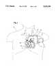
- FIG. 1is an anterior view of a patient implanted with a preferred embodiment of the invention.
- FIG. 2is a schematic view of the embodiment of FIG. 1.
- FIG. 3is an enlarged view of the embodiment of FIG. 1.
- FIG. 1shows an Implantable Cardioverter/Defibrillator (ICD) and flow sensor unit 10, including a single housing 12 and a flexible fiber optic line 14.
- the optic lineserves as a light conduit extending from the housing, and terminates at a distal tip 16.
- the entire unit 10is implanted in a patient 20, with the housing 12 located in the patient's pectoral or abdominal region.
- the optic line 14extends from the housing to an incision 21 in the patient's subclavian vein 22.
- the optic line 14passes through the incision, and extends downwardly through the vein into the heart 24, with the distal tip 16 positioned within the right ventricle 26.
- the optic linemay be secured to a wall of the right ventricle with the distal tip extending away from the wall.
- a sensing/pacing lead 27extends from the housing 12 into the ventricle 26, and is secured to the apex of the right ventricle using tines or a screw tip.
- Surgical implantationmay be achieved by encasing the optic line 14 in a semi-rigid hollow catheter, which may be inserted transvenously. The catheter is removed alter the line is positioned.
- the fiber optic line 14 and the sensing/pacing lead 27may be integrated into a single lead, with each component passing through a respective lumen of a multi-lumen lead, facilitating implantation.
- Such leadcould also include one or more defibrillation conductors, one or more sensing/pacing conductors, and may include an additional lumen through which a stylet may be inserted to facilitate implantation without the use of a catheter.
- the illustrated embodimentshows separate leads to provide clarity.
- FIG. 2shows the ICD and flow sensor unit 10.
- a green light-emitting diode (LED) 28emits a beam of light along a first beam path 30, through a collimating lens 32 that generates a beam of parallel rays. The beam then passes through a dichroic beam splitter 34, which transmits the green collimated beam, while reflecting primarily red light wavelengths. The transmitted beam then encounters a concentrating lens 40.
- a first end 39 of the optic line 14is positioned at the focal point of tile lens 40, so that the parallel rays of the beam are focused into the core of the optic line 14. The green beam is then transmitted through the line toward the line's distal tip 16.
- FIG. 3shows the optical details of the distal tip 16 of the optic line 14.
- the optic line 14includes a sheath 41 formed of silicone or other biocompatible material to permit long term use in the blood stream.
- a ruby 42is positioned over the terminus 44 of the line 14, and is sized so that at least a majority of green light transmitted through the line is intercepted and absorbed by the ruby 42.
- a protective coating 46surrounds the ruby, and minimizes tissue growth over time.
- a portion of the red fluorescent light emitted by the rubyis transmitted back up the optic line 14 to the housing 12.
- the red fluorescent lightre-enters the housing 12, and is collimated by lens 40 so that it follows a returning beam path 54.
- the returning beamencounters the dichroic beam splitter 34, which reflects the red returning beam.
- the returning beamthen passes through a lens 58, which focuses the light onto a silicon photodetector 60 that generates an electrical signal corresponding to the intensity of tile incident light as a function of time.
- a filter transmitting at 694 nmmay be used before or after lens 58 to improve the signal to noise performance of the sensor.
- the photodetectorhas an electrical output line 62 that carries the signal.
- a processor 66is connected to line 62, and processes the signal from the photodetector to determine the fluorescence duration, and thereby the temperature, of the ruby before and after heating. From the difference in ruby temperatures, the processor may estimate the blood flow within the ventricle, or at least determine whether the blood flow is likely above or below a predetermined threshold indicating that therapy may be required.
- the processoris electrically connected to conventional ICD circuitry 70, which provides cardiac therapy by selectably applying a voltage to the connected electrode sensing/pacing lead 27, or to a defibrillation lead electrode (not shown).
- the lead 27is capable of sensing the heart rate and providing Brady pacing or antitachycardia pacing.
- An additional return electrode(not shown) providing a "ground" for the high voltage shocks may be placed in the superior vena cava, or may use the housing of a pectorally implanted device.
- the therapy provided by the defibrillatoris not necessarily a defibrillation shock, but is frequently antitachycardia pacing or a cardioversion shock.
- the defibrillatorincludes a heart rate sensor (not shown) that permits activation of the flow sensor light source 28 only when the heart rate exceeds a rate that may be problematic.
- the devicemay be programmed to provide therapy only if the flow sensor processor 66 indicates a blood flow below the preselected rate.
- the processor 66 or ICD circuitry 70may also be programmed to apply therapy in response to the satisfaction of more complex conditions.
- a complex function of the heart rate, measured flow rate, characteristics of the patient, and other interacting variablesmay be used to determine when therapy is indicated.
- the method of operationoccurs in a preferred sequence. Basically, a baseline temperature is determined, the ruby is heated, and a second temperature is determined for comparison and analysis.
- the specific sequenceis as follows:
- the processorsenses a heart rate above a predetermined rate associated with tachyarrhythmia, the operation is initiated.
- Photodetectormeasures the decay time of the fluorescence received from the ruby.
- D. Processorintegrates the fluorescent signal to determine the fluorescent decay time, and calculates the baseline temperature.
- Photodetectormeasures the decay time of the fluorescence received from the ruby.
- D. Processorintegrates the fluorescent signal to determine the fluorescent decay time, and calculates the second temperature.
- A. Processorcompares the baseline and second temperatures to determine whether blood flow is below a predetermined threshold (as would be indicated by a relatively high second temperature due to a lack of cooling blood flow during the heating and subsequent steps.)
- the blood flow rate for a subject experiencing tachyarrhythmiais between 1 and 5 L/min, but generally less than 3 L/min.
- the difference between the flow rates of physiologic and pathological tachycardiais at least about a factor of five, which permits the disclosed method and apparatus to clearly distinguish between these conditions to determine whether to apply therapy.
- the rubyfluoresces red light at about 694 nm, and absorbs green light from 500 to 600 nm.
- Alternatives to the rubyinclude any material that has an emission that varies with temperature. These may include Neodymium YAG, Neodymium glass, and fluoroptic materials such as those offered by Luxtron Company of Santa Clara, Calif.
- the light sourcemay be provided by a green light-emitting diode emitting light at a wavelength of 500 to 600 nm.
- Alternativessuch as lasers, or other conventional sources emitting at similar wavelengths within the ruby's absorption bands may be used.
- a laser diode emitting at 780 or 830 nmwould be suitable for use with Neodymium YAG and Neodymium glass materials mentioned above.
- An alternative embodimentmeasures the ratio of emitted fluorescent spectral lines to determine the initial temperature and the final temperature of the temperature sensitive element.
- lightis not intended to limit the invention to visible wavelengths; a wider range of wavelengths may be used.
- the ruby's coating 46is preferably formed of a material formulated to prevent an accumulation of platelets on the distal tip from blocking the heat transfer path.
- a material formulated to prevent an accumulation of platelets on the distal tip from blocking the heat transfer pathis preferred.
- One suitable coatingis ParyleneTM, from Specialty Coating Systems of Indianapolis, Ind. A coating thickness of 2 ⁇ m and coefficient of friction of 0.05 to 0.10 is preferred.
- the optic lineis preferably a large core type having a functional diameter of 0.5 to 2.0 mm, permitting significant light flux for heating the ruby.
Landscapes
- Health & Medical Sciences (AREA)
- Physics & Mathematics (AREA)
- General Physics & Mathematics (AREA)
- Life Sciences & Earth Sciences (AREA)
- Engineering & Computer Science (AREA)
- Biophysics (AREA)
- Medical Informatics (AREA)
- Cardiology (AREA)
- Physiology (AREA)
- Aviation & Aerospace Engineering (AREA)
- Fluid Mechanics (AREA)
- Pathology (AREA)
- Biomedical Technology (AREA)
- Heart & Thoracic Surgery (AREA)
- Hematology (AREA)
- Molecular Biology (AREA)
- Surgery (AREA)
- Animal Behavior & Ethology (AREA)
- General Health & Medical Sciences (AREA)
- Public Health (AREA)
- Veterinary Medicine (AREA)
- Measuring Pulse, Heart Rate, Blood Pressure Or Blood Flow (AREA)
Abstract
Description
This invention relates to implantable cardioverter/defibrillators and more particularly to apparatus and method for discrimination of pathologic tachycardia from physiologic tachycardia.
The human heart may surlier from two classes of rhythmic disorders or arrhythmias: Bradycardia and tachyarrhythmia. Bradycardia occurs when the heart beats too slowly, and may be treated by a common pacemaker delivering low voltage (about 1 V) pacing pulses. Of concern here is tachyarrhythmia, which involves an abnormally high heart rate between about 100 to 200 beats per minute, but without hemodynamic or blood flow efficiency. Of particular concern is a ventricular tachycardia, in which the ventricles have not completely filled before they contract, thus diminishing the voltime of blood pumped. The pumping inefficiency is generally proportional to the heart rate. A severe form of tachyarrhythmia is fibrillation, which occurs at heart rates of 180 to 300 beats per minute, and involves erratic, disorganized beating that pumps virtually no blood.
Implantable cardioverters/defibrillators (ICD) or pulse generators are used for antitachycardia pacing to correct rapid heart rates by delivering a rapid sequence of pacing pulses of 1 to 10 volts to break the arrhythmia. ICD devices treat severe tachycardia with cardioversion, by delivering a shock of 100 to 750 volts synchronously with the peak of the heart's R-wave signal as detected by an electrocardiogram (ECG). Heart fibrillation receives similar therapy, but the erratic ECG signal may not provide a clear R-wave peak for synchronization.
Normally, the spacing between successive R-wave peaks is used to determine the heart rate. Extremely high or irregular heart rates clearly require therapy. Moderately elevated heart rates may be of ambiguous origin, either from healthy exercise, or from the disorders discussed above. To distinguish between these causes, treatment techniques have included measurement of blood pressure, oxygen saturation, Doppler ultrasound parameters, and ECG morphology. These techniques have limited accuracy and practicality, particularly outside of a clinical setting.
The present invention avoids the limitations of existing techniques and devices by providing a cardiac blood flow sensor that measures blood flow within the heart. The apparatus includes a light source and a photodetector within an implanted housing. The light source projects a beam through a flexible elongated light conduit having a first end optically connected to the housing and having a distal tip positioned within the patient's heart. The distal tip includes a ruby having fluorescent characteristics that vary with temperature. The temperature of the ruby is determined initially from the ruby fluorescence decay time. Then the beam is activated for a period of time to elevate the temperature of the ruby well above the ambient blood temperature. The temperature of the ruby is again determined from its fluorescence decay time. The elevated temperature difference from the initial temperature depends on the cooling effect of the blood flow. The cooling effect is greater during healthy blood flow than during tachyarrhythmia.
The fluorescent light is transmitted back through the conduit to the photodetector, which generates a signal that may be analyzed by a controller to determine whether a tachycardia is physiologic or pathologic in origin.
The flow sensor may be contained in a common housing with a defibrillator that is implanted in a patient. The sensor may remain inactive until a tachycardia is detected, upon which the light source is activated. The defibrillator may be activated only if the flow sensor has detected a blood flow rate below a predetermined level.
FIG. 1 is an anterior view of a patient implanted with a preferred embodiment of the invention.
FIG. 2 is a schematic view of the embodiment of FIG. 1.
FIG. 3 is an enlarged view of the embodiment of FIG. 1.
FIG. 1 shows an Implantable Cardioverter/Defibrillator (ICD) andflow sensor unit 10, including asingle housing 12 and a flexible fiberoptic line 14. The optic line serves as a light conduit extending from the housing, and terminates at adistal tip 16. Theentire unit 10 is implanted in apatient 20, with thehousing 12 located in the patient's pectoral or abdominal region. Theoptic line 14 extends from the housing to anincision 21 in the patient'ssubclavian vein 22. Theoptic line 14 passes through the incision, and extends downwardly through the vein into theheart 24, with thedistal tip 16 positioned within theright ventricle 26. The optic line may be secured to a wall of the right ventricle with the distal tip extending away from the wall. This configuration provides an angle that is more likely perpendicular to the direction ofblood flow 25, and may thereby improve the efficiency of the system. A sensing/pacing lead 27 extends from thehousing 12 into theventricle 26, and is secured to the apex of the right ventricle using tines or a screw tip. Surgical implantation may be achieved by encasing theoptic line 14 in a semi-rigid hollow catheter, which may be inserted transvenously. The catheter is removed alter the line is positioned. The fiberoptic line 14 and the sensing/pacing lead 27 may be integrated into a single lead, with each component passing through a respective lumen of a multi-lumen lead, facilitating implantation. Such lead could also include one or more defibrillation conductors, one or more sensing/pacing conductors, and may include an additional lumen through which a stylet may be inserted to facilitate implantation without the use of a catheter. The illustrated embodiment shows separate leads to provide clarity.
FIG. 2 shows the ICD andflow sensor unit 10. A green light-emitting diode (LED) 28 emits a beam of light along afirst beam path 30, through a collimatinglens 32 that generates a beam of parallel rays. The beam then passes through adichroic beam splitter 34, which transmits the green collimated beam, while reflecting primarily red light wavelengths. The transmitted beam then encounters a concentratinglens 40. A first end 39 of theoptic line 14 is positioned at the focal point oftile lens 40, so that the parallel rays of the beam are focused into the core of theoptic line 14. The green beam is then transmitted through the line toward the line'sdistal tip 16.
FIG. 3 shows the optical details of thedistal tip 16 of theoptic line 14. Theoptic line 14 includes asheath 41 formed of silicone or other biocompatible material to permit long term use in the blood stream. Aruby 42 is positioned over theterminus 44 of theline 14, and is sized so that at least a majority of green light transmitted through the line is intercepted and absorbed by theruby 42. Aprotective coating 46 surrounds the ruby, and minimizes tissue growth over time. A portion of the red fluorescent light emitted by the ruby is transmitted back up theoptic line 14 to thehousing 12. Returning to FIG. 2, the red fluorescent light re-enters thehousing 12, and is collimated bylens 40 so that it follows a returningbeam path 54. The returning beam encounters thedichroic beam splitter 34, which reflects the red returning beam. The returning beam then passes through alens 58, which focuses the light onto asilicon photodetector 60 that generates an electrical signal corresponding to the intensity of tile incident light as a function of time. A filter transmitting at 694 nm may be used before or afterlens 58 to improve the signal to noise performance of the sensor.
The photodetector has anelectrical output line 62 that carries the signal. Aprocessor 66 is connected toline 62, and processes the signal from the photodetector to determine the fluorescence duration, and thereby the temperature, of the ruby before and after heating. From the difference in ruby temperatures, the processor may estimate the blood flow within the ventricle, or at least determine whether the blood flow is likely above or below a predetermined threshold indicating that therapy may be required. The processor is electrically connected toconventional ICD circuitry 70, which provides cardiac therapy by selectably applying a voltage to the connected electrode sensing/pacing lead 27, or to a defibrillation lead electrode (not shown). Thelead 27 is capable of sensing the heart rate and providing Brady pacing or antitachycardia pacing. An additional return electrode (not shown) providing a "ground" for the high voltage shocks may be placed in the superior vena cava, or may use the housing of a pectorally implanted device. The therapy provided by the defibrillator is not necessarily a defibrillation shock, but is frequently antitachycardia pacing or a cardioversion shock. The defibrillator includes a heart rate sensor (not shown) that permits activation of the flowsensor light source 28 only when the heart rate exceeds a rate that may be problematic. The device may be programmed to provide therapy only if theflow sensor processor 66 indicates a blood flow below the preselected rate.
Theprocessor 66 orICD circuitry 70 may also be programmed to apply therapy in response to the satisfaction of more complex conditions. A complex function of the heart rate, measured flow rate, characteristics of the patient, and other interacting variables may be used to determine when therapy is indicated.
The method of operation occurs in a preferred sequence. Basically, a baseline temperature is determined, the ruby is heated, and a second temperature is determined for comparison and analysis. The specific sequence is as follows:
I. Initiation of Operation
A. If the processor senses a heart rate above a predetermined rate associated with tachyarrhythmia, the operation is initiated.
II. Baseline Temperature Determination
A. Brief illumination of the LED with an initial excitation pulse of 10 to 100 μsec duration.
B. Blanking pause of 10 μsec after brief illumination ceases, permitting the LED light to decay to dark after shutoff.
C. Photodetector measures the decay time of the fluorescence received from the ruby.
D. Processor integrates the fluorescent signal to determine the fluorescent decay time, and calculates the baseline temperature.
III. Heating of the Ruby
A. Prolonged illumination or heating pulse of the LED for approximately 1 second.
B. Blanking pause of 3 msec after brief illumination ceases, permitting dissipation of ruby fluorescence due to the heating pulse.
IV. Second Temperature Determination
A. Brief illumination of the LED with a final excitation pulse of 10 to 100 μsec duration.
B. Blanking pause of 10 μsec after brief illumination ceases, permitting the LED light to decay to dark after shutoff.
C. Photodetector measures the decay time of the fluorescence received from the ruby.
D. Processor integrates the fluorescent signal to determine the fluorescent decay time, and calculates the second temperature.
V. Analysis and Therapy
A. Processor compares the baseline and second temperatures to determine whether blood flow is below a predetermined threshold (as would be indicated by a relatively high second temperature due to a lack of cooling blood flow during the heating and subsequent steps.)
B. If blood flow is below the predetermined threshold, therapy in the form of an electrical pulse delivered via the sensing/pacing lead to the patient's heart.
It is not necessary to obtain an absolute temperature measurement. Only a relative difference between the fluorescent decay times before and after the heating step is needed to determine whether a tachycardia is physiologic or pathologic in origin. The vastly different blood flow characteristics between these two conditions permits useful analysis even with estimates that are accurate only to an order of magnitude, although the apparatus and method disclosed herein may be capable of more accurate measurements than are required. Normal blood flow rates vary among subjects at rest between 4 and 8 liters per minute (L/min); normal rates for exercising subjects (physiologic tachycardia) are about five times higher, typically about 15 to 30 L/min. The blood flow rate for a subject experiencing tachyarrhythmia (pathologic tachycardia) is between 1 and 5 L/min, but generally less than 3 L/min. The difference between the flow rates of physiologic and pathological tachycardia is at least about a factor of five, which permits the disclosed method and apparatus to clearly distinguish between these conditions to determine whether to apply therapy.
In the preferred embodiment, the ruby fluoresces red light at about 694 nm, and absorbs green light from 500 to 600 nm. Alternatives to the ruby include any material that has an emission that varies with temperature. These may include Neodymium YAG, Neodymium glass, and fluoroptic materials such as those offered by Luxtron Company of Santa Clara, Calif.
The light source may be provided by a green light-emitting diode emitting light at a wavelength of 500 to 600 nm. Alternatives such as lasers, or other conventional sources emitting at similar wavelengths within the ruby's absorption bands may be used. A laser diode emitting at 780 or 830 nm would be suitable for use with Neodymium YAG and Neodymium glass materials mentioned above.
An alternative embodiment measures the ratio of emitted fluorescent spectral lines to determine the initial temperature and the final temperature of the temperature sensitive element.
The use of the term "light" is not intended to limit the invention to visible wavelengths; a wider range of wavelengths may be used.
The ruby'scoating 46 is preferably formed of a material formulated to prevent an accumulation of platelets on the distal tip from blocking the heat transfer path. One suitable coating is Parylene™, from Specialty Coating Systems of Indianapolis, Ind. A coating thickness of 2 μm and coefficient of friction of 0.05 to 0.10 is preferred. The optic line is preferably a large core type having a functional diameter of 0.5 to 2.0 mm, permitting significant light flux for heating the ruby.
While the invention is described in terms of a preferred embodiment, the claims are not intended to be so limited.
Claims (19)
1. A method for discrimination between a pathologic tachycardia and a physiologic tachycardia in a patient comprising the steps of:
selecting a predetermined threshold indicative of tachycardia;
detecting the patient's heart rate;
comparing said detected heart rate with said predetermined threshold;
in response to detection of a heart rate above said predetermined threshold, illuminating a temperature sensitive element positioned within the patient's blood stream, then sensing the duration of fluorescent light emitted;
heating the temperature sensitive element;
waiting a predetermined period of time following said heating step;
after said predetermined period following the heating of the temperature sensitive element, illuminating the temperature sensitive element and then sensing the duration of fluorescent light emitted to measure the temperature of the temperature sensitive element to obtain a relative measure of blood flow; and
determining whether the tachycardia is physiologic or pathologic in origin based on the relative measure of blood flow.
2. The method of claim 1 wherein the step of heating the temperature sensitive element includes projecting light onto the temperature sensitive element.
3. The method of claim 1 wherein the step of measuring the temperature of the temperature sensitive element includes sensing fluorescent light emitted from the temperature sensitive element.
4. The method of claim 1 including the step of comparing emissions of fluorescent light from the temperature sensitive element before and after the heating step.
5. The method of claim 1 including the step of applying electrical therapy to the patient's heart in response to detection of a pathologic tachycardia.
6. An implantable cardiac therapy apparatus comprising:
a housing having a port for transmitting light between the housing interior and exterior;
a light source within the housing and in optical communication with the port, such that at least a portion of light emitted by the light source is transmitted along a first beam path between the light source and the port;
a photodetector having an electrical output, the photodetector being responsive to the intensity of light impinging thereon, the photodetector being positioned within the housing and in optical communication with the port, such that at least a portion of light entering the port is transmitted along a second beam path between the port and the detector to impinge on the photodetector;
a processor connected to the photodetector's electrical output;
a flexible elongated light conduit having a first end optically connected to the housing port, and a distal tip including a temperature sensitive element, such that light from the light source is transmitted through the conduit to the distal tip, and such that at least a portion of any light generated by the distal tip is transmitted to the photodetector to generate a signal;
means for illuminating the temperature sensitive element before heating the temperature sensitive element, then sensing the duration of fluorescent light emitted;
means for waiting a predetermined time after heating the temperature sensitive element, then illuminating the temperature sensitive element and sensing the duration of fluorescent light emitted; and
a pulse generator having an input connected to the processor for generating an electric pulse in a lead extending from an output port of the pulse generator.
7. The apparatus of claim 6 wherein the pulse generator is an implantable cardioverter/defibrillator.
8. The apparatus of claim 6 wherein the pulse generator is contained within the housing.
9. The apparatus of claim 6 wherein the temperature sensitive element emits light in proportion to its temperature after excitation with electromagnetic radiation.
10. The apparatus of claim 6 wherein the conduit comprises a fiber optic line.
11. The apparatus of claim 6 wherein at least a portion of the conduit is enclosed by a biocompatible sheath.
12. The apparatus of claim 6 wherein the processor includes means for calculating a blood flow rate.
13. The apparatus of claim 6 including a dichroic beam splitter within the housing and within the first and second beam paths, such that portions of the beam paths are coextensive with each other between the beam splitter and the port, and are separate from each other adjacent the respective light source and photodetector.
14. The apparatus of claim 6 including a heart rate sensor.
15. A method of measuring blood flow in the blood stream of a patient, the method comprising the steps:
determining a first baseline temperature by illuminating a light-emitting temperature sensitive element within the blood stream through a flexible conduit having a distal tip immersed in the patient's blood stream and analyzing light emitted therefrom;
heating the light-emitting temperature sensitive element;
waiting a predetermined time after heating the light-emitting temperature sensitive element;
determining a second temperature by illuminating a light-emitting temperature sensitive element and analyzing light emitted therefrom; and
analyzing the temperature change to determine the blood flow rate.
16. The method of claim 15 wherein the step of projecting the light includes stimulating fluorescence of the temperature sensitive element.
17. The method of claim 15 wherein the step of projecting the light includes projecting the light within the patient's heart.
18. The method of claim 15 including the step of detecting the patient's heart rate.
19. The method of claim 18 wherein the step of generating the light occurs in response to a detected heart rate above a preselected rate.
Priority Applications (1)
| Application Number | Priority Date | Filing Date | Title |
|---|---|---|---|
| US08/331,416US5520190A (en) | 1994-10-31 | 1994-10-31 | Cardiac blood flow sensor and method |
Applications Claiming Priority (1)
| Application Number | Priority Date | Filing Date | Title |
|---|---|---|---|
| US08/331,416US5520190A (en) | 1994-10-31 | 1994-10-31 | Cardiac blood flow sensor and method |
Publications (1)
| Publication Number | Publication Date |
|---|---|
| US5520190Atrue US5520190A (en) | 1996-05-28 |
Family
ID=23293875
Family Applications (1)
| Application Number | Title | Priority Date | Filing Date |
|---|---|---|---|
| US08/331,416Expired - Fee RelatedUS5520190A (en) | 1994-10-31 | 1994-10-31 | Cardiac blood flow sensor and method |
Country Status (1)
| Country | Link |
|---|---|
| US (1) | US5520190A (en) |
Cited By (63)
| Publication number | Priority date | Publication date | Assignee | Title |
|---|---|---|---|---|
| US5984954A (en)* | 1997-10-01 | 1999-11-16 | Boston Medical Technologies, Inc. | Methods and apparatus for R-wave detection |
| US6106481A (en)* | 1997-10-01 | 2000-08-22 | Boston Medical Technologies, Inc. | Method and apparatus for enhancing patient compliance during inspiration measurements |
| US20020091419A1 (en)* | 2000-07-13 | 2002-07-11 | Firlik Andrew D. | Methods and apparatus for effectuating a change in a neural-function of a patient |
| US6436053B1 (en) | 1997-10-01 | 2002-08-20 | Boston Medical Technologies, Inc. | Method and apparatus for enhancing patient compliance during inspiration measurements |
| US20020128689A1 (en)* | 2001-02-20 | 2002-09-12 | Connelly Patrick R. | Electromagnetic interference immune tissue invasive system |
| US20030055457A1 (en)* | 2001-08-30 | 2003-03-20 | Macdonald Stuart G. | Pulsewidth electrical stimulation |
| US20030074032A1 (en)* | 2001-10-15 | 2003-04-17 | Gliner Bradford Evan | Neural stimulation system and method responsive to collateral neural activity |
| US20030083728A1 (en)* | 2001-10-31 | 2003-05-01 | Wilson Greatbatch | Hermetic component housing for photonic catheter |
| US20030088274A1 (en)* | 2001-09-28 | 2003-05-08 | Vertis Neuroscience, Inc. | Method and apparatus for electrically stimulating cells implanted in the nervous system |
| US20030097161A1 (en)* | 2000-07-13 | 2003-05-22 | Firlik Andrew D. | Methods and apparatus for effectuating a lasting change in a neural-function of a patient |
| US20030125786A1 (en)* | 2000-07-13 | 2003-07-03 | Gliner Bradford Evan | Methods and apparatus for effectuating a lasting change in a neural-function of a patient |
| US20030144717A1 (en)* | 2002-01-28 | 2003-07-31 | Hagele Richard J. | Ceramic cardiac electrodes |
| US20030187490A1 (en)* | 2002-03-28 | 2003-10-02 | Gliner Bradford Evan | Electrode geometries for efficient neural stimulation |
| US20040015211A1 (en)* | 2002-06-04 | 2004-01-22 | Nurmikko Arto V. | Optically-connected implants and related systems and methods of use |
| US6711440B2 (en) | 2002-04-11 | 2004-03-23 | Biophan Technologies, Inc. | MRI-compatible medical device with passive generation of optical sensing signals |
| US20040061997A1 (en)* | 2002-09-30 | 2004-04-01 | Skinner David N. | Light-emitting lock device control element and electronic device including the same |
| US20040073270A1 (en)* | 2000-07-13 | 2004-04-15 | Firlik Andrew D. | Methods and apparatus for effectuating a lasting change in a neural-function of a patient |
| US6725092B2 (en) | 2002-04-25 | 2004-04-20 | Biophan Technologies, Inc. | Electromagnetic radiation immune medical assist device adapter |
| US6731979B2 (en) | 2001-08-30 | 2004-05-04 | Biophan Technologies Inc. | Pulse width cardiac pacing apparatus |
| US20040111127A1 (en)* | 2002-12-10 | 2004-06-10 | Gliner Bradford Evan | Systems and methods for enhancing or optimizing neural stimulation therapy for treating symptoms of Parkinson's disease and/or other movement disorders |
| US20040158298A1 (en)* | 2000-07-13 | 2004-08-12 | Gliner Bradford Evan | Systems and methods for automatically optimizing stimulus parameters and electrode configurations for neuro-stimulators |
| US20040181263A1 (en)* | 2001-03-08 | 2004-09-16 | Jeffrey Balzer | System and method for treating Parkinson's Disease and other movement disorders |
| US6795730B2 (en) | 2000-04-20 | 2004-09-21 | Biophan Technologies, Inc. | MRI-resistant implantable device |
| GB2401430A (en)* | 2003-04-23 | 2004-11-10 | Sensor Highway Ltd | Fluid flow measurement |
| US6829509B1 (en) | 2001-02-20 | 2004-12-07 | Biophan Technologies, Inc. | Electromagnetic interference immune tissue invasive system |
| US20050021107A1 (en)* | 2001-03-08 | 2005-01-27 | Firlik Andrew D. | Methods and apparatus for effectuating a lasting change in a neural-function of a patient |
| EP1266623B1 (en)* | 2000-03-23 | 2005-02-23 | Noriyasu Sakamoto | Diagnosis device and treatment device |
| US6925328B2 (en) | 2000-04-20 | 2005-08-02 | Biophan Technologies, Inc. | MRI-compatible implantable device |
| US20050171446A1 (en)* | 1999-02-02 | 2005-08-04 | Transonic Systems, Inc | Method and apparatus for determining a blood flow during a vascular access dysfunction corrective procedure |
| US20050197563A1 (en)* | 2002-07-25 | 2005-09-08 | Helfer Jeffrey L. | Optical MRI catheter system |
| US20050274589A1 (en)* | 2004-05-07 | 2005-12-15 | Vanderlande Industries Nederland B.V. | Device for sorting products |
| US20050277839A1 (en)* | 2004-06-10 | 2005-12-15 | Honeywell International, Inc. | Wireless flow measurement in arterial stent |
| US20060106431A1 (en)* | 2004-11-12 | 2006-05-18 | Allen Wyler | Systems and methods for selecting stimulation sites and applying treatment, including treatment of symptoms of Parkinson's disease, other movement disorders, and/or drug side effects |
| US20060174255A1 (en)* | 2005-02-03 | 2006-08-03 | Lite-On It Corporation | Apparatus for positioning clamper of optical disc device |
| US20070015981A1 (en)* | 2003-08-29 | 2007-01-18 | Benaron David A | Device and methods for the detection of locally-weighted tissue ischemia |
| US20070027371A1 (en)* | 2005-07-29 | 2007-02-01 | Spectros Corporation | Implantable tissue ischemia sensor |
| US20070043392A1 (en)* | 2000-07-13 | 2007-02-22 | Northstar Neuroscience, Inc. | Systems and methods for reducing the likelihood of inducing collateral neural activity during neural stimulation threshold test procedures |
| US20070088403A1 (en)* | 2005-10-19 | 2007-04-19 | Allen Wyler | Methods and systems for establishing parameters for neural stimulation |
| US20070088404A1 (en)* | 2005-10-19 | 2007-04-19 | Allen Wyler | Methods and systems for improving neural functioning, including cognitive functioning and neglect disorders |
| US20070179534A1 (en)* | 2005-10-19 | 2007-08-02 | Firlik Andrew D | Systems and methods for patient interactive neural stimulation and/or chemical substance delivery |
| US7302298B2 (en) | 2002-11-27 | 2007-11-27 | Northstar Neuroscience, Inc | Methods and systems employing intracranial electrodes for neurostimulation and/or electroencephalography |
| US20080009689A1 (en)* | 2002-04-09 | 2008-01-10 | Benaron David A | Difference-weighted somatic spectroscopy |
| US20080077190A1 (en)* | 2006-09-21 | 2008-03-27 | Cardiac Pacemakers, Inc. | Implantable Medical Device Header With Optical Interface |
| US20080130311A1 (en)* | 2001-08-31 | 2008-06-05 | Smith & Nephew, Inc., A Delaware Corporation | Solid-State Light Source |
| US20080139951A1 (en)* | 2006-12-08 | 2008-06-12 | Cardiac Pacemakers, Inc. | Detection of Stenosis |
| US20080188727A1 (en)* | 2002-04-09 | 2008-08-07 | Benaron David A | Broadband solid-state spectroscopy illuminator and method |
| US20080249591A1 (en)* | 2007-04-06 | 2008-10-09 | Northstar Neuroscience, Inc. | Controllers for implantable medical devices, and associated methods |
| US7483747B2 (en) | 2004-07-15 | 2009-01-27 | Northstar Neuroscience, Inc. | Systems and methods for enhancing or affecting neural stimulation efficiency and/or efficacy |
| US20090076567A1 (en)* | 2004-11-12 | 2009-03-19 | Northstar Neuroscience, Inc. | Electrode Configurations for Reducing Invasiveness and/or Enhancing Neural Stimulation Efficacy, and Associated Methods |
| US7565199B2 (en) | 2002-12-09 | 2009-07-21 | Advanced Neuromodulation Systems, Inc. | Methods for treating and/or collecting information regarding neurological disorders, including language disorders |
| US20090306735A1 (en)* | 2006-01-31 | 2009-12-10 | St. Jude Medial Ab | Implantable cardiac stimulator, device and system for monitoring the status of a cardiac lead |
| US7684866B2 (en) | 2003-08-01 | 2010-03-23 | Advanced Neuromodulation Systems, Inc. | Apparatus and methods for applying neural stimulation to a patient |
| US7729773B2 (en) | 2005-10-19 | 2010-06-01 | Advanced Neuromodualation Systems, Inc. | Neural stimulation and optical monitoring systems and methods |
| US7756584B2 (en) | 2000-07-13 | 2010-07-13 | Advanced Neuromodulation Systems, Inc. | Methods and apparatus for effectuating a lasting change in a neural-function of a patient |
| WO2013061280A1 (en)* | 2011-10-28 | 2013-05-02 | Hemodynamix Medical Systems Inc. | Fluid temperature and flow sensor apparatus and system for cardiovascular and other medical applications |
| US8527046B2 (en) | 2000-04-20 | 2013-09-03 | Medtronic, Inc. | MRI-compatible implantable device |
| US8718777B2 (en) | 2002-11-27 | 2014-05-06 | Advanced Neuromodulation Systems, Inc. | Methods and systems for intracranial neurostimulation and/or sensing |
| US8929991B2 (en) | 2005-10-19 | 2015-01-06 | Advanced Neuromodulation Systems, Inc. | Methods for establishing parameters for neural stimulation, including via performance of working memory tasks, and associated kits |
| US10463259B2 (en) | 2011-10-28 | 2019-11-05 | Three Rivers Cardiovascular Systems Inc. | System and apparatus comprising a multi-sensor catheter for right heart and pulmonary artery catheterization |
| US10722175B2 (en) | 2014-07-13 | 2020-07-28 | Hemocath Ltd. | System and apparatus comprising a multisensor guidewire for use in interventional cardiology |
| CN111486913A (en)* | 2020-04-26 | 2020-08-04 | 上海集迦电子科技有限公司 | Optical fiber flowmeter with fluorescent material and control method |
| US11272847B2 (en) | 2016-10-14 | 2022-03-15 | Hemocath Ltd. | System and apparatus comprising a multi-sensor catheter for right heart and pulmonary artery catheterization |
| US12402797B2 (en) | 2019-09-30 | 2025-09-02 | Hemocath Ltd. | Multi-sensor catheter for right heart and pulmonary artery catheterization |
Citations (12)
| Publication number | Priority date | Publication date | Assignee | Title |
|---|---|---|---|---|
| US4542987A (en)* | 1983-03-08 | 1985-09-24 | Regents Of The University Of California | Temperature-sensitive optrode |
| US4560286A (en)* | 1977-12-07 | 1985-12-24 | Luxtron Corporation | Optical temperature measurement techniques utilizing phosphors |
| US4621929A (en)* | 1983-10-12 | 1986-11-11 | Luxtron Corporation | Fiber optic thermal anemometer |
| US4688573A (en)* | 1984-05-24 | 1987-08-25 | Intermedics, Inc. | Temperature driven rate responsive cardiac pacemaker |
| US4729668A (en)* | 1986-04-22 | 1988-03-08 | The United States Of America As Represented By The United States Department Of Energy | Method and apparatus for optical temperature measurements |
| US4752141A (en)* | 1985-10-25 | 1988-06-21 | Luxtron Corporation | Fiberoptic sensing of temperature and/or other physical parameters |
| US4986671A (en)* | 1989-04-12 | 1991-01-22 | Luxtron Corporation | Three-parameter optical fiber sensor and system |
| US5005574A (en)* | 1989-11-28 | 1991-04-09 | Medical Engineering And Development Institute, Inc. | Temperature-based, rate-modulated cardiac therapy apparatus and method |
| US5040538A (en)* | 1989-09-05 | 1991-08-20 | Siemens-Pacesetter, Inc. | Pulsed light blood oxygen content sensor system and method of using same |
| US5174299A (en)* | 1991-08-12 | 1992-12-29 | Cardiac Pacemakers, Inc. | Thermocouple-based blood flow sensor |
| US5336244A (en)* | 1992-10-07 | 1994-08-09 | Medtronic, Inc. | Temperature sensor based capture detection for a pacer |
| US5370667A (en)* | 1992-04-03 | 1994-12-06 | Intermedics, Inc. | Device and method for automatically adjusting tachycardia recognition criteria based on detected parameter |
- 1994
- 1994-10-31USUS08/331,416patent/US5520190A/ennot_activeExpired - Fee Related
Patent Citations (12)
| Publication number | Priority date | Publication date | Assignee | Title |
|---|---|---|---|---|
| US4560286A (en)* | 1977-12-07 | 1985-12-24 | Luxtron Corporation | Optical temperature measurement techniques utilizing phosphors |
| US4542987A (en)* | 1983-03-08 | 1985-09-24 | Regents Of The University Of California | Temperature-sensitive optrode |
| US4621929A (en)* | 1983-10-12 | 1986-11-11 | Luxtron Corporation | Fiber optic thermal anemometer |
| US4688573A (en)* | 1984-05-24 | 1987-08-25 | Intermedics, Inc. | Temperature driven rate responsive cardiac pacemaker |
| US4752141A (en)* | 1985-10-25 | 1988-06-21 | Luxtron Corporation | Fiberoptic sensing of temperature and/or other physical parameters |
| US4729668A (en)* | 1986-04-22 | 1988-03-08 | The United States Of America As Represented By The United States Department Of Energy | Method and apparatus for optical temperature measurements |
| US4986671A (en)* | 1989-04-12 | 1991-01-22 | Luxtron Corporation | Three-parameter optical fiber sensor and system |
| US5040538A (en)* | 1989-09-05 | 1991-08-20 | Siemens-Pacesetter, Inc. | Pulsed light blood oxygen content sensor system and method of using same |
| US5005574A (en)* | 1989-11-28 | 1991-04-09 | Medical Engineering And Development Institute, Inc. | Temperature-based, rate-modulated cardiac therapy apparatus and method |
| US5174299A (en)* | 1991-08-12 | 1992-12-29 | Cardiac Pacemakers, Inc. | Thermocouple-based blood flow sensor |
| US5370667A (en)* | 1992-04-03 | 1994-12-06 | Intermedics, Inc. | Device and method for automatically adjusting tachycardia recognition criteria based on detected parameter |
| US5336244A (en)* | 1992-10-07 | 1994-08-09 | Medtronic, Inc. | Temperature sensor based capture detection for a pacer |
Cited By (156)
| Publication number | Priority date | Publication date | Assignee | Title |
|---|---|---|---|---|
| US6106481A (en)* | 1997-10-01 | 2000-08-22 | Boston Medical Technologies, Inc. | Method and apparatus for enhancing patient compliance during inspiration measurements |
| US6161037A (en)* | 1997-10-01 | 2000-12-12 | Boston Medical Technologies, Inc. | Methods and apparatus for R-wave detection |
| US6436053B1 (en) | 1997-10-01 | 2002-08-20 | Boston Medical Technologies, Inc. | Method and apparatus for enhancing patient compliance during inspiration measurements |
| US6740046B2 (en) | 1997-10-01 | 2004-05-25 | Boston Medical Technologies, Inc. | Method and apparatus for enhancing patient compliance during inspiration measurements |
| US5984954A (en)* | 1997-10-01 | 1999-11-16 | Boston Medical Technologies, Inc. | Methods and apparatus for R-wave detection |
| US20050171446A1 (en)* | 1999-02-02 | 2005-08-04 | Transonic Systems, Inc | Method and apparatus for determining a blood flow during a vascular access dysfunction corrective procedure |
| US6986744B1 (en) | 1999-02-02 | 2006-01-17 | Transonic Systems, Inc. | Method and apparatus for determining blood flow during a vascular corrective procedure |
| EP1266623B1 (en)* | 2000-03-23 | 2005-02-23 | Noriyasu Sakamoto | Diagnosis device and treatment device |
| US8527046B2 (en) | 2000-04-20 | 2013-09-03 | Medtronic, Inc. | MRI-compatible implantable device |
| US6795730B2 (en) | 2000-04-20 | 2004-09-21 | Biophan Technologies, Inc. | MRI-resistant implantable device |
| US6925328B2 (en) | 2000-04-20 | 2005-08-02 | Biophan Technologies, Inc. | MRI-compatible implantable device |
| US7305268B2 (en) | 2000-07-13 | 2007-12-04 | Northstar Neurscience, Inc. | Systems and methods for automatically optimizing stimulus parameters and electrode configurations for neuro-stimulators |
| US7146217B2 (en) | 2000-07-13 | 2006-12-05 | Northstar Neuroscience, Inc. | Methods and apparatus for effectuating a change in a neural-function of a patient |
| US7577481B2 (en) | 2000-07-13 | 2009-08-18 | Advanced Neuromodulation Systems, Inc. | Methods and apparatus for effectuating a lasting change in a neural-function of a patient |
| US20080161881A1 (en)* | 2000-07-13 | 2008-07-03 | Northstar Neuroscience, Inc. | Methods and apparatus for effectuating a lasting change in a neural-function of a patient |
| US20080161882A1 (en)* | 2000-07-13 | 2008-07-03 | Northstar Neuroscience, Inc. | Methods and apparatus for effectuating a lasting change in a neural-function of a patient |
| US20040158298A1 (en)* | 2000-07-13 | 2004-08-12 | Gliner Bradford Evan | Systems and methods for automatically optimizing stimulus parameters and electrode configurations for neuro-stimulators |
| US7236831B2 (en) | 2000-07-13 | 2007-06-26 | Northstar Neuroscience, Inc. | Methods and apparatus for effectuating a lasting change in a neural-function of a patient |
| US20030097161A1 (en)* | 2000-07-13 | 2003-05-22 | Firlik Andrew D. | Methods and apparatus for effectuating a lasting change in a neural-function of a patient |
| US20030125786A1 (en)* | 2000-07-13 | 2003-07-03 | Gliner Bradford Evan | Methods and apparatus for effectuating a lasting change in a neural-function of a patient |
| US8433414B2 (en) | 2000-07-13 | 2013-04-30 | Advanced Neuromodulation Systems, Inc. | Systems and methods for reducing the likelihood of inducing collateral neural activity during neural stimulation threshold test procedures |
| US20070043392A1 (en)* | 2000-07-13 | 2007-02-22 | Northstar Neuroscience, Inc. | Systems and methods for reducing the likelihood of inducing collateral neural activity during neural stimulation threshold test procedures |
| US7620456B2 (en) | 2000-07-13 | 2009-11-17 | Advanced Neuromodulation Systems, Inc. | Systems and methods for reducing the likelihood of inducing collateral neural activity during neural stimulation threshold test procedures |
| US20060200206A1 (en)* | 2000-07-13 | 2006-09-07 | Northstar Neuroscience, Inc. | Methods and apparatus for effectuating a lasting change in a neural-function of a patient |
| US20060195155A1 (en)* | 2000-07-13 | 2006-08-31 | Northstar Neuroscience, Inc. | Methods and apparatus for effectuating a lasting change in a neural-function of a patient |
| US7756584B2 (en) | 2000-07-13 | 2010-07-13 | Advanced Neuromodulation Systems, Inc. | Methods and apparatus for effectuating a lasting change in a neural-function of a patient |
| US8412335B2 (en) | 2000-07-13 | 2013-04-02 | Advanced Neuromodulation Systems, Inc. | Systems and methods for automatically optimizing stimulus parameters and electrode configurations for neuro-stimulators |
| US20040073270A1 (en)* | 2000-07-13 | 2004-04-15 | Firlik Andrew D. | Methods and apparatus for effectuating a lasting change in a neural-function of a patient |
| US8195300B2 (en) | 2000-07-13 | 2012-06-05 | Advanced Neuromodulation Systems, Inc. | Systems and methods for automatically optimizing stimulus parameters and electrode configurations for neuro-stimulators |
| US8065012B2 (en) | 2000-07-13 | 2011-11-22 | Advanced Neuromodulation Systems, Inc. | Methods and apparatus for effectuating a lasting change in a neural-function of a patient |
| US8073546B2 (en) | 2000-07-13 | 2011-12-06 | Advanced Neuromodulation Systems, Inc. | Methods and apparatus for effectuating a lasting change in a neural-function of a patient |
| US20020091419A1 (en)* | 2000-07-13 | 2002-07-11 | Firlik Andrew D. | Methods and apparatus for effectuating a change in a neural-function of a patient |
| US6760628B2 (en) | 2001-02-20 | 2004-07-06 | Biophan Technologies, Inc. | Electromagnetic interference immune tissue invasive system |
| US20020138124A1 (en)* | 2001-02-20 | 2002-09-26 | Helfer Jeffrey L. | Electromagnetic interference immune tissue invasive system |
| US6763268B2 (en) | 2001-02-20 | 2004-07-13 | Biophan Technologies, Inc. | Electromagnetic interference immune tissue invasive system |
| US6757566B2 (en) | 2001-02-20 | 2004-06-29 | Biophan Technologies, Inc. | Electromagnetic interference immune tissue invasive system |
| US6778856B2 (en) | 2001-02-20 | 2004-08-17 | Biophan Technologies, Inc. | Electromagnetic interference immune tissue invasive system |
| US20020138113A1 (en)* | 2001-02-20 | 2002-09-26 | Connelly Patrick R. | Electromagnetic interference immune tissue invasive system |
| WO2002065895A3 (en)* | 2001-02-20 | 2002-10-31 | Biophan Technologies Inc | An electromagnetic interference immune tissue invasive system |
| US6795736B2 (en) | 2001-02-20 | 2004-09-21 | Biophan Technologies, Inc. | Electromagnetic interference immune tissue invasive system |
| US6799069B2 (en) | 2001-02-20 | 2004-09-28 | Biophan Technologies, Inc. | Electromagnetic interference immune tissue invasive system |
| US20020133086A1 (en)* | 2001-02-20 | 2002-09-19 | Connelly Patrick R. | Electromagnetic interference immune tissue invasive system |
| US6819954B2 (en) | 2001-02-20 | 2004-11-16 | Biophan Technologies, Inc. | Electromagnetic interference immune tissue invasive system |
| US6819958B2 (en) | 2001-02-20 | 2004-11-16 | Biophan Technologies, Inc. | Electromagnetic interference immune tissue invasive system |
| US6829509B1 (en) | 2001-02-20 | 2004-12-07 | Biophan Technologies, Inc. | Electromagnetic interference immune tissue invasive system |
| US6845266B2 (en) | 2001-02-20 | 2005-01-18 | Biophan Technologies, Inc. | Electromagnetic interference immune tissue invasive system |
| US20020143258A1 (en)* | 2001-02-20 | 2002-10-03 | Weiner Michael L. | Electromagnetic interference immune tissue invasive system |
| US6850805B2 (en) | 2001-02-20 | 2005-02-01 | Biophan Technologies, Inc. | Electromagnetic interference immune tissue invasive system |
| US20020138108A1 (en)* | 2001-02-20 | 2002-09-26 | Weiner Michael L. | Electromagnetic interference immune tissue invasive system |
| US20050090886A1 (en)* | 2001-02-20 | 2005-04-28 | Biophan Technologies, Inc. | Medical device with an electrically conductive anti-antenna geometrical shaped member |
| US6901290B2 (en) | 2001-02-20 | 2005-05-31 | Biophan Technologies, Inc. | Electromagnetic interference immune tissue invasive system |
| US20020133202A1 (en)* | 2001-02-20 | 2002-09-19 | Connelly Patrick R. | Electromagnetic interference immune tissue invasive system |
| US6718203B2 (en) | 2001-02-20 | 2004-04-06 | Biophan Technologies, Inc. | Electromagnetic interference immune tissue invasive system |
| US7047074B2 (en) | 2001-02-20 | 2006-05-16 | Biophan Technologies, Inc. | Electromagnetic interference immune tissue invasive system |
| US20020138110A1 (en)* | 2001-02-20 | 2002-09-26 | Connelly Patrick R. | Electromagnetic interference immune tissue invasive system |
| US7013174B2 (en) | 2001-02-20 | 2006-03-14 | Biophan Technologies, Inc. | Electromagnetic interference immune tissue invasive system |
| US6954674B2 (en) | 2001-02-20 | 2005-10-11 | Biophan Technologies, Inc. | Electromagnetic interference immune tissue invasive system |
| US7010357B2 (en) | 2001-02-20 | 2006-03-07 | Biophan Technologies, Inc. | Electromagnetic interference immune tissue invasive system |
| US6993387B2 (en) | 2001-02-20 | 2006-01-31 | Biophan Technologies, Inc. | Electromagnetic interference immune tissue invasive system |
| US20020128689A1 (en)* | 2001-02-20 | 2002-09-12 | Connelly Patrick R. | Electromagnetic interference immune tissue invasive system |
| US7450996B2 (en) | 2001-02-20 | 2008-11-11 | Medtronic, Inc. | Medical device with an electrically conductive anti-antenna geometrical shaped member |
| US6718207B2 (en) | 2001-02-20 | 2004-04-06 | Biophan Technologies, Inc. | Electromagnetic interference immune tissue invasive system |
| US7672730B2 (en) | 2001-03-08 | 2010-03-02 | Advanced Neuromodulation Systems, Inc. | Methods and apparatus for effectuating a lasting change in a neural-function of a patient |
| US7299096B2 (en) | 2001-03-08 | 2007-11-20 | Northstar Neuroscience, Inc. | System and method for treating Parkinson's Disease and other movement disorders |
| US20040181263A1 (en)* | 2001-03-08 | 2004-09-16 | Jeffrey Balzer | System and method for treating Parkinson's Disease and other movement disorders |
| US20050021107A1 (en)* | 2001-03-08 | 2005-01-27 | Firlik Andrew D. | Methods and apparatus for effectuating a lasting change in a neural-function of a patient |
| US7054686B2 (en) | 2001-08-30 | 2006-05-30 | Biophan Technologies, Inc. | Pulsewidth electrical stimulation |
| US20030055457A1 (en)* | 2001-08-30 | 2003-03-20 | Macdonald Stuart G. | Pulsewidth electrical stimulation |
| US6731979B2 (en) | 2001-08-30 | 2004-05-04 | Biophan Technologies Inc. | Pulse width cardiac pacing apparatus |
| US8545077B2 (en) | 2001-08-31 | 2013-10-01 | Smith & Nephew, Inc. | Solid-state light source |
| US20110205751A1 (en)* | 2001-08-31 | 2011-08-25 | Smith & Nephew, Inc. | Solid-state light source |
| US20080130311A1 (en)* | 2001-08-31 | 2008-06-05 | Smith & Nephew, Inc., A Delaware Corporation | Solid-State Light Source |
| US7959338B2 (en)* | 2001-08-31 | 2011-06-14 | Smith & Nephew, Inc. | Solid-state light source |
| US20150346427A1 (en)* | 2001-08-31 | 2015-12-03 | Smith & Nephew, Inc. | Solid-state light source |
| US20030088274A1 (en)* | 2001-09-28 | 2003-05-08 | Vertis Neuroscience, Inc. | Method and apparatus for electrically stimulating cells implanted in the nervous system |
| US20030074032A1 (en)* | 2001-10-15 | 2003-04-17 | Gliner Bradford Evan | Neural stimulation system and method responsive to collateral neural activity |
| US7831305B2 (en) | 2001-10-15 | 2010-11-09 | Advanced Neuromodulation Systems, Inc. | Neural stimulation system and method responsive to collateral neural activity |
| US20030083728A1 (en)* | 2001-10-31 | 2003-05-01 | Wilson Greatbatch | Hermetic component housing for photonic catheter |
| US6988001B2 (en) | 2001-10-31 | 2006-01-17 | Biophan Technologies, Inc. | Hermetic component housing for photonic catheter |
| US20030144717A1 (en)* | 2002-01-28 | 2003-07-31 | Hagele Richard J. | Ceramic cardiac electrodes |
| US6968236B2 (en) | 2002-01-28 | 2005-11-22 | Biophan Technologies, Inc. | Ceramic cardiac electrodes |
| US20070179584A1 (en)* | 2002-03-28 | 2007-08-02 | Northstar Neuroscience, Inc. | Electrode geometries for efficient neural stimulation |
| US20030187490A1 (en)* | 2002-03-28 | 2003-10-02 | Gliner Bradford Evan | Electrode geometries for efficient neural stimulation |
| US8126568B2 (en) | 2002-03-28 | 2012-02-28 | Advanced Neuromodulation Systems, Inc. | Electrode geometries for efficient neural stimulation |
| US7221981B2 (en) | 2002-03-28 | 2007-05-22 | Northstar Neuroscience, Inc. | Electrode geometries for efficient neural stimulation |
| US20100198030A1 (en)* | 2002-04-09 | 2010-08-05 | Spectros Corporation | Solid-State General Illumination With Broadband White LED And Integrated Heat Sink |
| US20080287758A1 (en)* | 2002-04-09 | 2008-11-20 | Benaron David A | Illuminator probe with memory device and method |
| US20090187086A1 (en)* | 2002-04-09 | 2009-07-23 | Benaron David A | Integrated White LED Illuminator and Color Sensor Detector System and Method |
| US20080188727A1 (en)* | 2002-04-09 | 2008-08-07 | Benaron David A | Broadband solid-state spectroscopy illuminator and method |
| US20080009689A1 (en)* | 2002-04-09 | 2008-01-10 | Benaron David A | Difference-weighted somatic spectroscopy |
| US6711440B2 (en) | 2002-04-11 | 2004-03-23 | Biophan Technologies, Inc. | MRI-compatible medical device with passive generation of optical sensing signals |
| US6725092B2 (en) | 2002-04-25 | 2004-04-20 | Biophan Technologies, Inc. | Electromagnetic radiation immune medical assist device adapter |
| US20040015211A1 (en)* | 2002-06-04 | 2004-01-22 | Nurmikko Arto V. | Optically-connected implants and related systems and methods of use |
| US7280870B2 (en)* | 2002-06-04 | 2007-10-09 | Brown University Research Foundation | Optically-connected implants and related systems and methods of use |
| US20050197563A1 (en)* | 2002-07-25 | 2005-09-08 | Helfer Jeffrey L. | Optical MRI catheter system |
| US20050203378A1 (en)* | 2002-07-25 | 2005-09-15 | Helfer Jeffrey L. | Optical MRI catheter system |
| US7389137B2 (en) | 2002-07-25 | 2008-06-17 | Biophan Technologies, Inc. | Optical MRI catheter system |
| US6980848B2 (en) | 2002-07-25 | 2005-12-27 | Biopham Technologies Inc. | Optical MRI catheter system |
| US20040061997A1 (en)* | 2002-09-30 | 2004-04-01 | Skinner David N. | Light-emitting lock device control element and electronic device including the same |
| US9427585B2 (en) | 2002-11-01 | 2016-08-30 | Advanced Neuromodulation Systems, Inc. | Systems and methods for enhancing or optimizing neural stimulation therapy for treating symptoms of parkinsons disease and or other movement disorders |
| US8718777B2 (en) | 2002-11-27 | 2014-05-06 | Advanced Neuromodulation Systems, Inc. | Methods and systems for intracranial neurostimulation and/or sensing |
| US7302298B2 (en) | 2002-11-27 | 2007-11-27 | Northstar Neuroscience, Inc | Methods and systems employing intracranial electrodes for neurostimulation and/or electroencephalography |
| US20080071323A1 (en)* | 2002-11-27 | 2008-03-20 | Lowry David W | Methods and Systems Employing Intracranial Electrodes for Neurostimulation and/or Electroencephalography |
| US7565199B2 (en) | 2002-12-09 | 2009-07-21 | Advanced Neuromodulation Systems, Inc. | Methods for treating and/or collecting information regarding neurological disorders, including language disorders |
| US20070112393A1 (en)* | 2002-12-10 | 2007-05-17 | Northstar Neuroscience, Inc. | Systems and methods for enhancing or optimizing neural stimulation therapy for treating symptoms of parkinson's disease and/or other movement disorders |
| US7236830B2 (en) | 2002-12-10 | 2007-06-26 | Northstar Neuroscience, Inc. | Systems and methods for enhancing or optimizing neural stimulation therapy for treating symptoms of Parkinson's disease and/or other movement disorders |
| US7353064B2 (en) | 2002-12-10 | 2008-04-01 | Northstar Neuroscience, Inc. | Systems and methods for enhancing or optimizing neural stimulation therapy for treating symptoms of movement disorders and/or other neurologic dysfunction |
| US20040111127A1 (en)* | 2002-12-10 | 2004-06-10 | Gliner Bradford Evan | Systems and methods for enhancing or optimizing neural stimulation therapy for treating symptoms of Parkinson's disease and/or other movement disorders |
| GB2401430B (en)* | 2003-04-23 | 2005-09-21 | Sensor Highway Ltd | Fluid flow measurement |
| GB2401430A (en)* | 2003-04-23 | 2004-11-10 | Sensor Highway Ltd | Fluid flow measurement |
| US7684866B2 (en) | 2003-08-01 | 2010-03-23 | Advanced Neuromodulation Systems, Inc. | Apparatus and methods for applying neural stimulation to a patient |
| US20070015981A1 (en)* | 2003-08-29 | 2007-01-18 | Benaron David A | Device and methods for the detection of locally-weighted tissue ischemia |
| US20050274589A1 (en)* | 2004-05-07 | 2005-12-15 | Vanderlande Industries Nederland B.V. | Device for sorting products |
| US20050277839A1 (en)* | 2004-06-10 | 2005-12-15 | Honeywell International, Inc. | Wireless flow measurement in arterial stent |
| US8606361B2 (en) | 2004-07-15 | 2013-12-10 | Advanced Neuromodulation Systems, Inc. | Systems and methods for enhancing or affecting neural stimulation efficiency and/or efficacy |
| US7983762B2 (en) | 2004-07-15 | 2011-07-19 | Advanced Neuromodulation Systems, Inc. | Systems and methods for enhancing or affecting neural stimulation efficiency and/or efficacy |
| US7483747B2 (en) | 2004-07-15 | 2009-01-27 | Northstar Neuroscience, Inc. | Systems and methods for enhancing or affecting neural stimulation efficiency and/or efficacy |
| US11786729B2 (en) | 2004-07-15 | 2023-10-17 | Advanced Neuromodulation Systems, Inc. | Systems and methods for enhancing or affecting neural stimulation efficiency and/or efficacy |
| US20060253170A1 (en)* | 2004-11-12 | 2006-11-09 | Northstar Neuroscience, Inc. | Systems and methods for selecting stimulation sites and applying treatment, including treatment of symptoms of parkinson's disease, other movement disorders, and/or drug side effects |
| US7908009B2 (en) | 2004-11-12 | 2011-03-15 | Advanced Neuromodulation Systems, Inc. | Systems and methods for selecting stimulation sites and applying treatment, including treatment of symptoms of Parkinson's disease, other movement disorders, and/or drug side effects |
| US20090076567A1 (en)* | 2004-11-12 | 2009-03-19 | Northstar Neuroscience, Inc. | Electrode Configurations for Reducing Invasiveness and/or Enhancing Neural Stimulation Efficacy, and Associated Methods |
| US20060106431A1 (en)* | 2004-11-12 | 2006-05-18 | Allen Wyler | Systems and methods for selecting stimulation sites and applying treatment, including treatment of symptoms of Parkinson's disease, other movement disorders, and/or drug side effects |
| US7437196B2 (en) | 2004-11-12 | 2008-10-14 | Northstar Neuroscience, Inc. | Systems and methods for selecting stimulation sites and applying treatment, including treatment of symptoms of Parkinson's disease, other movement disorders, and/or drug side effects |
| US7565200B2 (en) | 2004-11-12 | 2009-07-21 | Advanced Neuromodulation Systems, Inc. | Systems and methods for selecting stimulation sites and applying treatment, including treatment of symptoms of Parkinson's disease, other movement disorders, and/or drug side effects |
| US20060259095A1 (en)* | 2004-11-12 | 2006-11-16 | Northstar Neuroscience, Inc. | Systems and methods for selecting stimulation sites and applying treatment, including treatment of symptoms of Parkinson's disease, other movement disorders, and/or drug side effects |
| US7742820B2 (en) | 2004-11-12 | 2010-06-22 | Advanced Neuromodulation Systems, Inc. | Systems and methods for selecting stimulation sites and applying treatment, including treatment of symptoms of parkinson's disease, other movement disorders, and/or drug side effects |
| US7917225B2 (en) | 2004-11-12 | 2011-03-29 | Advanced Neuromodulation Systems, Inc. | Systems and methods for selecting stimulation sites and applying treatment, including treatment of symptoms of parkinson's disease, other movement disorders, and/or drug side effects |
| US20060174255A1 (en)* | 2005-02-03 | 2006-08-03 | Lite-On It Corporation | Apparatus for positioning clamper of optical disc device |
| US20070027371A1 (en)* | 2005-07-29 | 2007-02-01 | Spectros Corporation | Implantable tissue ischemia sensor |
| US20100312081A1 (en)* | 2005-07-29 | 2010-12-09 | Spectros Corporation | Implantable Tissue Ischemia Sensor |
| JP2009502360A (en)* | 2005-07-29 | 2009-01-29 | スペクトロス コーポレイション | Implantable tissue ischemia sensor |
| US7813778B2 (en)* | 2005-07-29 | 2010-10-12 | Spectros Corporation | Implantable tissue ischemia sensor |
| WO2007016437A3 (en)* | 2005-07-29 | 2007-05-31 | Spectros Corp | Implantable tissue ischemia sensor |
| US20070088403A1 (en)* | 2005-10-19 | 2007-04-19 | Allen Wyler | Methods and systems for establishing parameters for neural stimulation |
| US8706241B2 (en) | 2005-10-19 | 2014-04-22 | Advanced Neuromodulation Systems, Inc. | System for patent interactive neural stimulation with robotic facilitation of limb movement |
| US20070179534A1 (en)* | 2005-10-19 | 2007-08-02 | Firlik Andrew D | Systems and methods for patient interactive neural stimulation and/or chemical substance delivery |
| US8929991B2 (en) | 2005-10-19 | 2015-01-06 | Advanced Neuromodulation Systems, Inc. | Methods for establishing parameters for neural stimulation, including via performance of working memory tasks, and associated kits |
| US7856264B2 (en) | 2005-10-19 | 2010-12-21 | Advanced Neuromodulation Systems, Inc. | Systems and methods for patient interactive neural stimulation and/or chemical substance delivery |
| US7729773B2 (en) | 2005-10-19 | 2010-06-01 | Advanced Neuromodualation Systems, Inc. | Neural stimulation and optical monitoring systems and methods |
| US20110092882A1 (en)* | 2005-10-19 | 2011-04-21 | Firlik Andrew D | Systems and methods for patient interactive neural stimulation and/or chemical substance delivery |
| US20070088404A1 (en)* | 2005-10-19 | 2007-04-19 | Allen Wyler | Methods and systems for improving neural functioning, including cognitive functioning and neglect disorders |
| US20090306735A1 (en)* | 2006-01-31 | 2009-12-10 | St. Jude Medial Ab | Implantable cardiac stimulator, device and system for monitoring the status of a cardiac lead |
| EP1981588A4 (en)* | 2006-01-31 | 2010-03-31 | St Jude Medical | IMPLANTABLE CARDIAC STIMULATOR, DEVICE AND SYSTEM FOR MONITORING THE CONDITION OF A CARDIAC BYPASS |
| US8224421B2 (en) | 2006-01-31 | 2012-07-17 | St. Jude Medical Ab | Implantable cardiac stimulator, device and system for monitoring the status of a cardiac lead |
| US8290592B2 (en) | 2006-09-21 | 2012-10-16 | Cardiac Pacemakers, Inc. | Implantable medical device header with optical interface |
| US20080077190A1 (en)* | 2006-09-21 | 2008-03-27 | Cardiac Pacemakers, Inc. | Implantable Medical Device Header With Optical Interface |
| US20080139951A1 (en)* | 2006-12-08 | 2008-06-12 | Cardiac Pacemakers, Inc. | Detection of Stenosis |
| US20080249591A1 (en)* | 2007-04-06 | 2008-10-09 | Northstar Neuroscience, Inc. | Controllers for implantable medical devices, and associated methods |
| WO2013061280A1 (en)* | 2011-10-28 | 2013-05-02 | Hemodynamix Medical Systems Inc. | Fluid temperature and flow sensor apparatus and system for cardiovascular and other medical applications |
| US10463259B2 (en) | 2011-10-28 | 2019-11-05 | Three Rivers Cardiovascular Systems Inc. | System and apparatus comprising a multi-sensor catheter for right heart and pulmonary artery catheterization |
| US11197619B2 (en) | 2011-10-28 | 2021-12-14 | Three Rivers Cardiovascular Systems Inc. | System and apparatus comprising a multi-sensor catheter for right heart and pulmonary artery catheterization |
| US9504392B2 (en) | 2011-10-28 | 2016-11-29 | Three Rivers Cardiovascular Systems Inc. | Apparatus, system and methods for measuring a blood pressure gradient |
| US10722175B2 (en) | 2014-07-13 | 2020-07-28 | Hemocath Ltd. | System and apparatus comprising a multisensor guidewire for use in interventional cardiology |
| US11272847B2 (en) | 2016-10-14 | 2022-03-15 | Hemocath Ltd. | System and apparatus comprising a multi-sensor catheter for right heart and pulmonary artery catheterization |
| US12402797B2 (en) | 2019-09-30 | 2025-09-02 | Hemocath Ltd. | Multi-sensor catheter for right heart and pulmonary artery catheterization |
| CN111486913A (en)* | 2020-04-26 | 2020-08-04 | 上海集迦电子科技有限公司 | Optical fiber flowmeter with fluorescent material and control method |
Similar Documents
| Publication | Publication Date | Title |
|---|---|---|
| US5520190A (en) | Cardiac blood flow sensor and method | |
| US5601611A (en) | Optical blood flow measurement apparatus and method and implantable defibrillator incorporating same | |
| US8165676B2 (en) | Optical sensor and method for detecting a patient condition | |
| US5174299A (en) | Thermocouple-based blood flow sensor | |
| US8260415B2 (en) | Optical sensor and method for detecting a patient condition | |
| US5354318A (en) | Method and apparatus for monitoring brain hemodynamics | |
| EP2548616B1 (en) | Evaluation device | |
| US4967748A (en) | O2 level responsive system for and method of treating a malfunctioning heart | |
| EP2001356B1 (en) | Apparatus for using an optical hemodynamic sensor to identify an unstable arrhythmia | |
| EP1145737B1 (en) | Medical device | |
| CN102015018B (en) | Hemodynamic Stability Identification Based on Pressure and Impedance | |
| EP1620173B1 (en) | History-dependent pacing interval determination for antitachycardia pacing | |
| US5431172A (en) | Method for detecting tachyarrhythmia of a heart by measuring patient activity and partial pressure of blood oxygen | |
| EP2548615A1 (en) | Determination device and determination method | |
| EP2640266B1 (en) | Coefficent determination for total hemoglobin concentration indices | |
| EP2548614A1 (en) | Calculation device and calculation method | |
| BR112020005143B1 (en) | METHOD AND PROVISION FOR CLEANING A CHANNEL | |
| WO2009123951A1 (en) | Temperature based systems and methods for tachycardia discrimination and therapy | |
| US7563231B2 (en) | Rapid thermal detection of cardiac output change | |
| Res et al. | P wave recognition and atrial stimulation with fractally iridium coated VDD single pass leads | |
| Hynes et al. | An evaluation of long‐term stimulation thresholds by measurement of chronic strength duration curves | |
| US20130225947A1 (en) | Implantable medical device | |
| WO2007095578A2 (en) | Rapid thermal detection of cardiac output change |
Legal Events
| Date | Code | Title | Description |
|---|---|---|---|
| AS | Assignment | Owner name:VENTRITEX, INC., CALIFORNIA Free format text:ASSIGNMENT OF ASSIGNORS INTEREST;ASSIGNORS:BENEDICT, GEORGE JOHN;FAYRAM, TIMOTHY ALAN;REEL/FRAME:007217/0194;SIGNING DATES FROM 19941026 TO 19941030 | |
| AS | Assignment | Owner name:PACESETTER, INC., CALIFORNIA Free format text:MERGER;ASSIGNOR:VENTRITEX, INC.;REEL/FRAME:008842/0454 Effective date:19970515 | |
| FPAY | Fee payment | Year of fee payment:4 | |
| FEPP | Fee payment procedure | Free format text:PAYOR NUMBER ASSIGNED (ORIGINAL EVENT CODE: ASPN); ENTITY STATUS OF PATENT OWNER: LARGE ENTITY Free format text:PAYER NUMBER DE-ASSIGNED (ORIGINAL EVENT CODE: RMPN); ENTITY STATUS OF PATENT OWNER: LARGE ENTITY | |
| FPAY | Fee payment | Year of fee payment:8 | |
| REMI | Maintenance fee reminder mailed | ||
| LAPS | Lapse for failure to pay maintenance fees | ||
| STCH | Information on status: patent discontinuation | Free format text:PATENT EXPIRED DUE TO NONPAYMENT OF MAINTENANCE FEES UNDER 37 CFR 1.362 | |
| FP | Lapsed due to failure to pay maintenance fee | Effective date:20080528 |