US5519804A - Universal splice tray - Google Patents
Universal splice trayDownload PDFInfo
- Publication number
- US5519804A US5519804AUS08/263,705US26370594AUS5519804AUS 5519804 AUS5519804 AUS 5519804AUS 26370594 AUS26370594 AUS 26370594AUS 5519804 AUS5519804 AUS 5519804A
- Authority
- US
- United States
- Prior art keywords
- splice
- channels
- base member
- tray
- holder
- Prior art date
- Legal status (The legal status is an assumption and is not a legal conclusion. Google has not performed a legal analysis and makes no representation as to the accuracy of the status listed.)
- Expired - Fee Related
Links
- 239000000835fiberSubstances0.000claimsabstractdescription119
- 239000013307optical fiberSubstances0.000claimsabstractdescription24
- 238000003491arrayMethods0.000claimsabstract2
- 239000004033plasticSubstances0.000claimsdescription17
- 239000000463materialSubstances0.000claimsdescription16
- 239000012858resilient materialSubstances0.000claimsdescription4
- 238000005452bendingMethods0.000claimsdescription3
- 230000001681protective effectEffects0.000description21
- 238000004873anchoringMethods0.000description7
- 210000005069earsAnatomy0.000description4
- 238000007789sealingMethods0.000description4
- 239000006260foamSubstances0.000description3
- 230000004927fusionEffects0.000description3
- 238000003780insertionMethods0.000description3
- 230000037431insertionEffects0.000description3
- 230000013011matingEffects0.000description3
- 229920004142LEXAN™Polymers0.000description2
- 230000004075alterationEffects0.000description2
- 230000005540biological transmissionEffects0.000description2
- 238000004891communicationMethods0.000description2
- 238000013461designMethods0.000description2
- 238000000034methodMethods0.000description2
- 230000035939shockEffects0.000description2
- JOYRKODLDBILNP-UHFFFAOYSA-NEthyl urethaneChemical compoundCCOC(N)=OJOYRKODLDBILNP-UHFFFAOYSA-N0.000description1
- 229910000831SteelInorganic materials0.000description1
- NIXOWILDQLNWCW-UHFFFAOYSA-Nacrylic acid groupChemical groupC(C=C)(=O)ONIXOWILDQLNWCW-UHFFFAOYSA-N0.000description1
- 230000001154acute effectEffects0.000description1
- 230000000712assemblyEffects0.000description1
- 238000000429assemblyMethods0.000description1
- 230000004888barrier functionEffects0.000description1
- 239000006185dispersionSubstances0.000description1
- 239000008393encapsulating agentSubstances0.000description1
- 238000005516engineering processMethods0.000description1
- 230000007613environmental effectEffects0.000description1
- 239000011521glassSubstances0.000description1
- 239000003365glass fiberSubstances0.000description1
- 239000012510hollow fiberSubstances0.000description1
- 238000007654immersionMethods0.000description1
- 230000001771impaired effectEffects0.000description1
- 239000007788liquidSubstances0.000description1
- 230000007246mechanismEffects0.000description1
- 238000012986modificationMethods0.000description1
- 230000004048modificationEffects0.000description1
- 229920000515polycarbonatePolymers0.000description1
- 239000004417polycarbonateSubstances0.000description1
- 230000008707rearrangementEffects0.000description1
- 238000011084recoveryMethods0.000description1
- 230000008439repair processEffects0.000description1
- 230000003763resistance to breakageEffects0.000description1
- 230000000284resting effectEffects0.000description1
- 239000012812sealant materialSubstances0.000description1
- 239000007787solidSubstances0.000description1
- 239000010959steelSubstances0.000description1
- XLYOFNOQVPJJNP-UHFFFAOYSA-NwaterSubstancesOXLYOFNOQVPJJNP-UHFFFAOYSA-N0.000description1
Images


Classifications
- G—PHYSICS
- G02—OPTICS
- G02B—OPTICAL ELEMENTS, SYSTEMS OR APPARATUS
- G02B6/00—Light guides; Structural details of arrangements comprising light guides and other optical elements, e.g. couplings
- G02B6/24—Coupling light guides
- G02B6/36—Mechanical coupling means
- G02B6/38—Mechanical coupling means having fibre to fibre mating means
- G02B6/3807—Dismountable connectors, i.e. comprising plugs
- G02B6/3873—Connectors using guide surfaces for aligning ferrule ends, e.g. tubes, sleeves, V-grooves, rods, pins, balls
- G02B6/3874—Connectors using guide surfaces for aligning ferrule ends, e.g. tubes, sleeves, V-grooves, rods, pins, balls using tubes, sleeves to align ferrules
- G02B6/3878—Connectors using guide surfaces for aligning ferrule ends, e.g. tubes, sleeves, V-grooves, rods, pins, balls using tubes, sleeves to align ferrules comprising a plurality of ferrules, branching and break-out means
- G—PHYSICS
- G02—OPTICS
- G02B—OPTICAL ELEMENTS, SYSTEMS OR APPARATUS
- G02B6/00—Light guides; Structural details of arrangements comprising light guides and other optical elements, e.g. couplings
- G02B6/44—Mechanical structures for providing tensile strength and external protection for fibres, e.g. optical transmission cables
- G02B6/4439—Auxiliary devices
- G02B6/4471—Terminating devices ; Cable clamps
- G02B6/44765—Terminating devices ; Cable clamps with means for strain-relieving to exterior cable layers
Definitions
- This inventionrelates to an optical fiber cable closure and to the component parts thereof. More particularly, the invention relates to a closure capable of accepting and anchoring any of a large number of different fiber optic cables and of holding and protecting a large number of optical fiber splices regardless of the particular commercially available splices used.
- the cablesmay take any of a number of forms such as a plurality of fibers contained within a tubular protective member, thereby forming a core or bundled together in protective loose tubes surrounding a central strength member.
- the fibersmay be arrayed side by side on a ribbon member, with a plurality of such ribbons being stacked to form a high fiber count cable, and which are then enclosed in a protective plastic tube or jacket.
- splicesare necessary for joining the ends of cables, and the fibers contained within them. It is necessary, therefore, to enclose the splices in a closure to contain and protect the splices of two or more fiber optic cables.
- a splice closureis used wherein the wire splices are stored and protected. Because of the innate strength of wire, it can be sharply bent to meet space limitations, and slack wire within the enclosure may be tightly coiled. Glass optical fibers, on the other hand, are of extremely small diameter and are relatively fragile, therefore, optical fibers must be treated more carefully in placing them, and their splices, within an enclosure. Thus, transmission capabilities may be impaired if the fiber is bent to less than an allowable bending radius to the point where the transmitted light is no longer completely contained within the fiber. In addition, the fibers are brittle and do not possess the strength and resistance to breakage that metallic wire does, hence, when bent too sharply, the fibers may break.
- optical fiber cableis not amenable to splicing using techniques applicable to wire type splicing.
- the glass fiberscannot be twisted, tied, or tightly coiled in the same manner as individual wires, nor can they be crimped or tightly bent without breakage.
- the closureInasmuch as, at the splice point, the cable is opened up and the base fibers exposed, the only protection afforded the fibers is provided by the closure, which can provide only one or two layers of protection from the outside environment, the requirements therefor are more stringent than for the cable, which normally provides several layers of protection.
- the closuremust anchor all cables stored therewithin, and it must be capable of withstanding torsional and axial loads transmitted by the cable to the closure so that the splices are protected from these loads.
- the closuremust also seal the inner and outer sheaths of the cables and maintain the seal integrity under extreme environmental conditions. The sealing must also provide a moisture barrier sufficient to prevent any moisture from reaching the fiber optic splices.
- Additional requirements for the closureare its ability to provide adequate fiber storage for slack fiber without damaging the fibers and without increasing signal attenuation; the ability to store any type of splice, such as, for example, discrete or mass mechanical, or discrete or mass fusion type splices while dampening and reducing vibration and other forces that tend to damage the splice or splices; and the ability to provide adequate grounding for the metallic strength members of the cables.
- the closuremust also have the capacity to accept the highest fiber count cables available on the market.
- the closureitself is offered to customers as a basic shell without the components for anchoring and sealing the cables, for routing and positioning the fibers, for housing and protecting the splices, for grounding the metallic strength members of the cables, and for encapsulating the closure itself within a protective shell.
- the various components to be used with the closuremust be ordered separately.
- each customerorders specific kits designed to accommodate the particular size cables, number of fibers, and splices to be used.
- the present inventionis directed to a splice closure having the various components to form a complete closure assembly, wherein the components are capable of handling a wide range of cable sizes and splice configurations.
- the inventionis described hereinafter in terms of an assembly comprising the basic UCBI closure shell with a plurality of components of novel design and universal utility, but it is to be understood that the principles of the invention are applicable to other types of closures, that being discussed hereinafter being by way of example only.
- the splice closureitself comprises a metallic base member and a cover which, when assembled, form an enclosure open at each end for receiving fiber optic cables to be spliced to each other.
- each openingcan accommodate two cables.
- Each of the cables entering and leaving the closureis anchored to the closure member by means of a grip block assembly which firmly grips the cable and which is mounted within the closure by means of a threaded stud and nut.
- the grip block assemblycomprises a lower grip member having first and second pivoted arms and an upper grip member having first and second depending actuating pins which is mounted on the lower grip member by means of a clamping bolt.
- a grounding plateis attached to the upper grip member by means of the clamping bolt and bears against a grounding strap which, in the fully assembled state, bears against the metallic armor or strength member of the cable being gripped.
- the clamping boltis tightened, forcing the upper grip member toward the lower grip member.
- the grip block assemblyis mounted on the cable between an inboard and an outboard grommet which are, in turn mounted in racetrack grommets forming part of a gasket between the base member and the cover of the closure housing.
- the stripped end of the cableincludes a large numbers of fiber bundles, either of the ribbon base type or the fiber base type, which must be separated and organized so that the individual fibers may be spliced to corresponding fibers in the exit cable.
- a fiber splitteris used to separate and route the fiber bundles.
- the splitter of the inventioncomprises a body portion of a clear or transparent rigid plastic material having, at one end, a plurality of hollow fiber bundle receiving axially extending hollow fingers arranged in two rows of six fingers each, with the fingers of one row being staggered relative to the fingers of the other row.
- the fiber bundlesare each encased in plastic protection sleeves which fit over the fingers.
- a fiber finger insert having two more rows of similarly staggered fingershas depending ears with openings therein which are adapted to snap over projections on the splitter body to lock the insert in place over the first set of fingers thereby increasing splitter capacity to twenty-four bundles.
- the end of the splitterhas a plurality of upstanding, spaced teeth defining fiber ribbon receiving spaces therebetween.
- Each ribbonis encased in an oval shaped sleeve, and the sleeves can be stacked vertically with vertical orientation in the spaces between the teeth.
- each splittercan accommodate twenty-four fiber bundles in the one embodiment, or twenty fiber ribbons in the other embodiment.
- the other end of the body portion of the splitteri.e., the cable end, has a split neck portion for receiving therein one end of a core tube insert.
- a pair of slots in the interior walls of the neck portionare adapted to receive projections on the core tube insert to hold the core tube in position.
- the external diameter of the core tube insertis stepped, with a first, smaller diameter portion being adapted to fit inside of the core tube of the cable, with the end of the core tube butting against the step at the start of the larger diameter portion of the insert.
- a plastic protective sleeve having an inner diameter slightly greater than the outside diameter of the larger diameter portion of the insertis fitted over the core tube and is adapted to receive and hold the larger diameter portion of the insert.
- the stepped, tubular portion of the insert as noted beforeis split to form a slot extending along the length thereof to facilitate positioning the fiber bundles and to insure that the insert fits within the protective sleeve.
- the coveris a flat member of preferably clear plastic having first and second depending slotted arms which are adapted to fit within corresponding recesses in the side walls of the splitter body. Within each recess is a projecting lug which is adapted to engage the slot in the corresponding arm of cover member to hold it firmly in place on the splitter body.
- the individual fibersare then spliced to corresponding fibers in the cable which either enters from the other end of the splice closure to form an in-line closure splice or the same end to form a butt splice.
- the fibersAfter the fibers have been spliced together it is necessary to store them in a container or splice tray for protection of the splices.
- the splice traymust also store the existing slack fiber that leads to and exits from the splice, without exceeding the maximum allowable bend (or minimum allowable bend radius) of the fiber.
- the splice traymust be capable of holding both splices and slack fibers in place against vibration, sudden impact, twisting, and the like.
- an elongated splice traywhich is mounted within the base member upon first and second leaf extension support members, which are bolted to the interior of the base member and form supporting brackets for each end of the splice tray.
- Each extension memberhas, at one end thereof, a transverse pin which, in position, extends parallel to the longitudinal axis of the closure.
- a leaf memberAt each end of the splice tray, at one bottom corner thereof, is a leaf member having a hole therein adapted to receive the pin on the extension member for holding the tray in place on the extension member.
- a pinoriented the same as the pin on the extension member so that a second splice tray may be mounted above and affixed to the first place tray. In this way, splice trays may be stacked within the enclosure.
- the splice trayhas, at each end thereof, a circular fiber storage hub with overlying retainers around which slack fiber is wound to prevent any slack fibers from lying loose in the tray.
- Centrally located in the trayare a pair of receptacles for receiving and retaining protective splice inserts which are adapted to be snapped into place within the tray.
- the insertshave a plurality of protective slots into which the individual splices are to be inserted and held in place by resilient means, and a plurality of fiber pass through channels for aligning and protecting the fibers leading to the splices.
- the splice trayis provided with a hinged transparent lid which completely covers the fibers and splices within the tray.
- the assembly of splice closureis completed by the addition of the closure cover which is sealed and bolted to the closure base.
- the coverhas resilient inserts therein which bear against the components mounted in the base to protect them from shock and other forces to which they might be subjected.
- a protective shellwhich comprises a base portion and a cover portion which fit over and completely cover the closure within a defined interior space having a volume greater than the volume occupied by the closure.
- Both the base portion and the cover portion of the shellhave longitudinally extending mating flanges adapted to be sealed together with a resilient grommet between the mating surfaces of the flanges.
- the splice closure assembly of the present inventionas described in the foregoing, is universal in the sense that the components thereof can accommodate cables, fibers, and splices of varying sizes and configurations without alteration, thereby eliminating the necessity of "customizing" the splice closure for the particular use to which it is to be put.
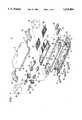
- FIG. 1is an exploded perspective view of the splice closure of the present invention
- FIG. 2is an exploded perspective view of the grip block of the present invention
- FIGS. 3A and 3Bare elevation views of the grip block of FIG. 2;
- FIG. 4is a detail of the cable grounding lug disposition in the grip block of FIG. 2;
- FIG. 5is an exploded perspective view of the splitter of the present invention.
- FIG. 6is a perspective view of a portion of the splitter of FIG. 5, with optical fibers in place;
- FIG. 7is a detail of a ribbon type optical fiber assembly
- FIG. 8is a perspective view of the splitter as adapted to handle ribbon fibers of the type shown in FIG. 7;
- FIG. 9is a perspective view of the modified splitter of FIG. 8 with the ribbons in place;
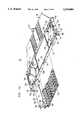
- FIG. 10is a perspective view of the splice tray of the present invention.
- FIG. 11is a plan view of the splice tray of FIG. 10;
- FIG. 12is a front elevation view of the splice tray of FIGS. 10 and 11;
- FIG. 13is a plan view of the underside of the lid or cover of the splice tray of FIG. 10;
- FIG. 14is a plan view of the splice holder for use in the splice tray of FIG. 10;
- FIG. 15is a plan view of one component of the splice holder of FIG. 14.
- FIG. 16is a plan view of another component of the splice holder of FIG. 14;
- FIG. 17is a perspective view of the component depicted in FIG. 16;
- FIG. 18is a diagrammatic depiction of a typical rotary mechanical splice
- FIG. 19is a plan view of a splice holder for the splice of FIG. 18.
- FIG. 20is a perspective view of the splice holder of FIG. 19.
- FIG. 1there is shown an exploded view of a splice closure 11, more particularly, an AT&T UCB1 type of closure, and the various component parts which, when assembled, make up a complete closure assembly.
- Closure 11comprises a base portion 12 and a cover portion 13 which is designed to be bolted to base portion 12 after the components have been assembled with the cables, fibers, and splices, none of which are shown, in their assigned positions.
- Base 12has a trough-like configuration with first and second longitudinally extruding flanges 14 and 16 having a plurality of bolt holes 17,17 which match corresponding bolt holes 18, 18 in flanges 19 and 21 of cover 13 for securing the latter thereto.
- First and second end compartments 22 and 23are formed in base 12 by means of walls or septa 24 and 26, respectively, which have semi-circular cut-outs therein for receiving universal grommet receiving seal members 27 and 28 of a race-track grommet 29.
- Grommet 29which is made of a suitable flexible, compressible urethane material, also functions as a sealing gasket between the flanges 14 and 19 and 16 and 21 of the base 12 and cover 13.
- Grommet receiving members 27 and 28are spaced apart and studs 31 and 32 extend therebetween.
- grommet receiving member 27is adapted to receive outboard grommets 33 and 34, which hold optical fiber cables 36 and 37
- grommet receiving member 28is adapted to receive inboard grommets 38 and 39, which hold optical fiber bundles 41 and 42.
- first and second universal grip blocks 43 and 44which are mounted to studs 31 and 32 respectively, as will be discussed more fully hereinafter, and which both anchor cables 36 and 37 and supply a grounding path for the metallic parts thereof.
- An additional grounding member, plate 46is mounted as by bolting to base 12 and functions primarily to ground the central strength member of those cables which have such.
- the other end of base portion 12has first and second grommet plugs 47 and 48 which are insertable in the receiving members 27 and 28 to help seal that end of the assembly. It is equally possible that cables may be introduced into that end of the base 12, in which case plugs 47 and 48 are not used, and a grommet and grip block assembly like that at the other end is used for anchoring, grounding, and sealing the ends of the closure.
- first and second leaf extension support members 51 and 52which are adapted to receive and support a splice tray 53, or a stack of such trays, as will be discussed more fully hereinafter.
- first and second fiber splitters 54 and 56Interposed between fiber bundles 41 and 42, and splice tray 53, are first and second fiber splitters 54 and 56 which, as pointed out hereinbefore, are used to separate and route the individual fibers and fiber bundles. As with the other components shown in FIG. 1, the splitters 54 and 56 will be discussed in greater detail hereinafter.
- the fibers thus arranged and segregatedare then inserted in splice tray 53, with the splices themselves, whether of the rotary type or the butt type, being contained in either one of two splice tray inserts 57 or 58, depending upon the type of splice used, and the lid 59 of tray 53 is snapped shut.
- First and second clamp members 61 and 62are bolted to base portion 12 and cover and seal the regions 22 and 23 with the grommets and grip blocks in place.
- a pair of blocks 63 and 64 of resilient materialare inserted into cover 13 which is then bolted in place onto base member 12, thereby completing the splice closure assembly 11.
- the splice closure assembly 11 of FIG. 1, with the various components shown,is a universal closure in the sense that it is capable of insuring a sealed protective environment for splices of varying sizes and configurations without the necessity of "customizing" the various components, and can accommodate a wide range of cable and fiber sizes and configurations.
- certain key ones of the componentsare also universal in the same sense and contribute to the overall versatility and utility of the splice closure.
- the mechanism used to anchor cables in the splice closure 11 of FIG. 1 as well as other types of such closuresis the grip block assembly, depicted as elements 43 and 44 in FIG. 1. Torsional or axial loads transmitted by the fiber optic cable are isolated by the grip block assembly and prevented from reaching and disturbing the fiber optic splices. The grip block also must ground the metallic parts of the cable to the metallic closure.
- the grip blocks 43 and/or 44in addition to withstanding one hundred pounds (100 lbs.) pull out cable load and one hundred eighty degrees (180°) cable rotation, must be capable of anchoring all fiber optic cables from approximately 0.40 inches diameter to 0.96 inches diameter with the cable, regardless of size, centered in the grip block so as to be coaxial with the grommet receiving members 27 and 28.
- the grip blocksmust be capable of grounding all fiber optic cables within the aforementioned range having metallic shielding or metallic strength members, or both.
- FIG. 2there is shown a perspective view of a portion of the grip block assembly 43. It is to be understood that all grip blocks to be used with splice closure 11 are identical with the possible exception of the cable grounding arrangement, as will be discussed hereinafter. It should be understood further that the grip block assembly 43 is adaptable for use with splice closures other than the UCB1 or UCB2 closures, although the following discussion is directed to use of the grip block with either the UCB1 or UCB2 closures.
- Grip block 43comprises a base member 66, preferably of suitable plastic material, first and second cable engaging pivoted levers 67 and 68 (for clarity only lever 67 is shown in FIG. 2), and a cap member 69.
- Base member 66has arcuate bearing surfaces 71, 72, 73, and 74 formed thereon upon which partially circular lobes 76,76 of levers 67 and 68 ride, as best seen in FIGS. 3A and 3B.
- Member 66also has cut out portions 77 and 78, the ends of which are shaped to accommodate tangs 79, 79 on levers 67 and 68.
- Base member 66also has an arcuate cut-out portion 65 upon which the cable to be gripped initially rests, as best seen in FIG. 3A.
- First and second columns 81 and 82 and third and fourth columns 83 and 84extend upwards from base 66, with columns 81 and 82 positioned on either side of a bolt hole 86 and columns 83 and 84 on either side of a bolt hole 87. Both holes 86 and 87 extend completely through base member 66.
- Columns 81, 82, 83 and 84have bores 88,88 therein, only two of which are shown, to receive pivot pins 89,89 which extend through bores 91,91 in levers 67 and 68, thereby pivotally mounting levers 67 and 68 to the columns 81, 82, 83, and 84.
- the front surfaces of the tangs 79,79 of levers 67 and 68have first and second arcuate portions 92,92 which, as best seen in FIG. 3B, are adapted to engage the cable being gripped by grip block assembly 43.
- the lobes 76,76are connected by a first transverse member 93 having cut out portions 94,94 which provide access to camming surfaces 96,96 on the tops of lobes 76,76, only one of which is shown in FIG. 2.
- Lobes 76,76are also joined by a strength member 97.
- Cap member 69comprises a rectangular member having four depending actuating pins 98, 99 (not shown) 101, and 102 at the comers thereof, which are pointed, as shown, and which are adapted to bear against the camming surfaces 96,96 of levers 67 and 68.
- the top surface of cap member 69has an arcuate recess 103 extending along its length, the purpose of which will be discussed hereinafter.
- Bolt holes 104,104extend through cap 69 and are adapted to be aligned with holes 86 and 87 when cap member 69 is in place in the assembly.
- the top of cap member 69also has a transverse recess 106 extending thereacross which will also be discussed hereinafter.
- a pair of holes 107,107are drilled through cap member 69 and are aligned with recess 106, as shown.
- the bottom surface of cap member 69has a transverse toothed serrated arcuate cut-out portion or groove 108 which is adapted to grip the cable being held by grip block 43, as best seen in FIG. 3B.
- the serrationsare shown as extending longitudinally of cut-out 108, they may, and preferably do, extend transversely thereof, i.e., normal to the longitudinal axis of the cable, thereby resisting axial stress on the cable.
- the serrationsmay be of knurled configuration, thereby affording maximum resistance to both transverse and axial stresses on the cable.
- FIG. 3Ais an elevation view of grip block 43 prior to its assembly, with a cable, shown in dashed lines, in place resting in cut-out portion 65.
- the grip block assembly 43includes a bonding plate 109 having bent ends 111 and 112 which fit into cut-out portions 113,113 in cap 69.
- Plate 109has a longitudinally extending V-shaped rib 114 which rides in arcuate cut-out portion 103 of cap 69.
- Bolt holes 116,116align with bolt holes 104, 104 in cap 69, and an assembly bolt 117 passes holes 116, 104, and 86, and mates with a nut 118 which rests in a shaped recess 119 in base 66.
- the other bolt holes 116, 104, and 87permit passage of one of the threaded studs 31 or 32 for anchoring the grip block assembly to the base portion 12 of closure 11 by means of a nut, not shown.
- pins 98, 99, 101 and 102bear against the camming surfaces 96,96 of levers 67 and 68, forcing the levers to pivot around pins 89,89 to bring surfaces 92,92 into engagement with the cable.
- FIG. 4there is shown a partial cross-sectional view of a grounding arrangement for use with a cable having a metallic shielding member 118 and steel strength members 119, only one of which is shown.
- a grounding clip 121is crimped around member 118 after the cable has been stripped to expose member 118, and one end of a grounding lug 122 is inserted between member 118 of the cable and clip 121, making good metallic contact with each.
- the grounding clip 121is not necessary and the end of the grounding lug 122 is inserted between member 118 and the next adjacent outer layer of the cable.
- lug 122is bent upward and into slot or recess 106 and then bent back upon itself, as shown.
- cap 69When cap 69 is tightened down, the V-shaped rib 114 of plate 109 bears against the folded lug 122, deforming it into cut-out portion 103 and thereby insuring positive metallic contact between plate 109 and lug 122.
- a solid ground pathis established between metallic member 118 and closure base 12 through lug 122, plate 109, and stud 31 with its nut in place.
- Strength members 119,119are bent upward into holes 107 as shown, and, because of their relative rigidity, function to assist in holding the grip block from shifting or otherwise moving.
- the grip closure and the grip block assemblyare the subject of U.S.
- the splitterWhen the end of an optical fiber cable is opened and prepared for splicing, it is essential that the individual fibers be protected and organized for easy accessibility when the closure is re-entered. Additionally, they must be protected from possible damage resulting from subsequent splicing procedures. These desiderata are best achieved through the use of a fiber splitter, which fits onto the end of the cable and separates and routes the fibers along individual paths. Heretofore, separate or individual splitters, depending upon the number and type of fibers to be organized, have been made available upon order. In accordance with the universatility concept of the present invention, the splitter is made to accept, without, alteration, any number of fibers up to a maximum, in multiples of twelve.
- FIG. 5there is shown a first embodiment of the splitter of the invention for separating and routing twenty-four fibers.
- the splitter 54comprises a base member 127 of preferably a clear plastic material such as a hard transparent polycarbonate, having affixed thereto a first set of twelve hollow split, substantially tubular fingers 128,128 arranged in two rows, one superposed over the other, wherein the fingers in one row are laterally offset from the fingers in the other row, as shown.
- Each of the fingers 128is in the form of a split hollow cylinder and is adapted to receive an individual fiber, as shown in FIG. 6.
- a second set of fingers in the form of a fiber insert member 129having two rows of split fingers 131,131, staggered in the same manner as fingers 128, has first and second depending latching members or ears 132, 133.
- ear 133is bifurcated to form a roughly U-shaped member which is adapted to fit over a projecting wedge shaped lug 134 on base member 127.
- Ear 132is constructed in the same manner to fit over a lug 136, not shown, so that insert 129 can be snapped into place in superposed relationship to the first set of fingers 128, 128 and firmly held by the projecting lugs 134 and 136 which bear against the transverse portion of the U-shaped member.
- Base 127has a neck portion 137 which has first and second opposed vertical slots 138 and 139, each slot being bridged at the top thereof by bridges 141 and 142.
- the slotsform opposed channels, as shown in FIG. 5.
- a core tube insert member 143has a body portion 144 having a substantially U-shape, and a tube insert member 146 extending therefrom.
- Insert member 146has a first section 147 in the shape of a split hollow cylinder and extending therefrom a second section 148 of lesser diameter or cross-section than cylinder 147.
- Section 148is adapted to be slipped into the core tube of the cable, as shown in FIG. 6, with the end of the core tube butting against the step formed between sections 147 and 148.
- Body portion 144has first and second protruding ribs 149 and 151 having notched ends 152 and 153 respectively. Ribs 149 and 151, when insert member 143 is joined to base member 127, are inserted into vertical slots 138 and 139, and notches 152 and 153 snap under bridges 142 and 141 respectively to hold the two parts firmly together.
- insert 143is positioned under the fiber core tube as shown in FIG. 6, and the individual fibers of the cable are routed to the proper fingers 128, 128 and 131, 131. Suitable plastic tubes 154, 154 are placed over the fingers 128, 128 to protect the bare fibers from possible damage.
- a transparent cap 156is mounted on base member 127. Cap 156 has first and second latching members 157 and 158, only 157 being shown in FIG. 5, which as in the manner of latching ears 132 and 133 are bifurcated to form a U-shaped latching member 127.
- Base memberhas first and second wedge shaped projections, not shown, over which ears 157 and 158 snap when cap 156 is pressed down onto base member 127, and which hold cap 156 firmly in place.
- the wedge shaped projectionsare located in channels 159 and 161 formed in the upstanding side walls 162 and 163 of base member 127.
- FIGS. 8 and 9there is shown a splitter 168 as modified to accommodate ribbon type optical fiber groupings, as shown in FIG. 7.
- Each such ribbon 166has twelve fibers aligned in a side by side arrangement, and the ribbon 166 is encased in a suitable oval shaped protective tube 167.
- the principal aim of the splitter 168 of FIG. 8is to allow the individual ribbons 166 to be separated and organized for subsequent splicing and, to this end, splitter 168 has a base member 170 having, at the exit end thereof, a comb-like structure of a plurality of upstanding spaced fingers 169, 169 forming slots for receiving the encased ribbons.
- FIGS. 8As shown in FIGS.
- splitter 168is substantially identical to splitter 54 of FIGS. 5 and 6.
- the bases 127 and 170, the insert 143, the member 129 and the cap 156are cast of clear or transparent acrylic, for example, in a parts tree from which they are individually removable.
- the userhas available all of the necessary components for a splitter accommodating a plurality of individual fibers or a splitter accommodating a plurality of fiber ribbons.
- the splitter of the inventionis extremely compact, in those cases where large number of fibers or ribbons are to be sorted and routed, a plurality of splitters may be used, there being sufficient space in the splice case 11 to accommodate such a plurality of splitters.
- FIGS. 5 through 9The splitter as shown in FIGS. 5 through 9 is the subject of U.S. patent application Ser. No. 08/263,707, filed concurrently herewith on Jun. 22, 1994 in the names of Denis E. Burek, Marc D. Jones and Philip M. Thomas.
- optical fibersAfter optical fibers have been spliced, it is necessary that they be stored and protected, and that the slack fiber on either side of the splice be stored in a manner such that the critical bend radius of the fiber is not exceeded, i.e., that the bend radius not be too small, thereby making sharp bends. Both the splices and the slack fibers must be held in a place despite vibration, impact shock, twisting, and water immersion, for example. To this end, the splice tray 53 depicted in FIG. 1 is used.
- the splice tray 53as will be discussed more fully hereinafter, is designed to accept mechanical, fusion, and rotary splices, with a capacity of twenty-four splices. Further, the splice tray 53 is designed to hold and protect virtually any commercially available splice.
- FIG. 10there is shown an exploded perspective view of the splice tray 53 of the invention, which comprises a base member 171 of suitable rigid plastic material having a longitudinal axis as seen in FIG. 11, the lid or top plate 59 of clear Lexan® plastic, for example, and a splice holder 173 (either element 57 or 58 in FIG. 1) adapted to be snapped into place and firmly held in base member 171.
- a splice holder 173either element 57 or 58 in FIG. 1
- the lidimparts a twist to the fibers leading to the splice, which is undesirable.
- the front wall 208 of base member 171has a cut-out portion 174 having a bridge 176 across the top thereof for receiving a latch member 177 on lid 59.
- Lid 59is pivotally mounted on base member 171 in a manner to be discussed hereinafter, and when lid 59 is pivoted over base member 171 to close the case or tray 53, the wedge shaped latch member 177 engages bridge 176 and opening 174 to latch the cover to the base.
- splice tray 53is, in use, mounted on support members 51 and 52, support member 51 being shown in FIG. 10.
- the end wallhas a split 178, 178 therein, thereby forming leaves 179, 179, each of which has a depending leaf 181,181 with a bore 182, 182 extending therethrough.
- Support member 51, and identical support member 52, not shown,comprises a flat plate 183 at the front end of which is a transversely extending pivot pin 184, which is adapted to fit within bore 182 on leaf 181 of member 179.
- Plate 183has cut outs 186, 186 immediately adjacent pin 184 to allow leaf 181 to fit therein.
- either end of plate 183is a depending mounting bracket or stand-off 187, which is bored (as shown) to permit passage of a mounting bolt for mounting support member 51 on base member 12.
- a latch member 188configured in a manner similar to latch 177.
- tray 53which is the configuration of all trays to be used, has, at the front comers thereof directly above leaves 181, 181, mounting pins 191,191, which perform the same function as pins 184, 184 on support members 51 and 52.
- top members 192, 192At the rear upper corners of base 171 are top members 192, 192, each having a rear edge 193 which is adapted to receive latch 188 to lock each succeeding tray to the immediately preceding one.
- a plurality of traysmay, where the number of splices dictates, be stacked on top of each other and locked in place.
- the resiliency of leaf members 179, 179 and latches 188, 188is such that the stack of trays can readily be disassembled when necessary.
- lid 59comprises a transparent sheet of material such as Lexan® having a forward or front edge 194 upon which latch member 177 is mounted to depend therefrom, and a rear edge 196, with the sheet having a trapezoidal shape, as shown.
- edge 196At each end of the edge 196 are pins 197, 197 which are adapted to fit within slots 198, 198 at the rear of base member 171.
- a cylindrically shaped member 199depends from the central portion of edge 196 and the ends thereof terminate in pins 201,201, which are adapted to fit within spaced slots 202, 202 in the rear wall of base member 171.
- cover 172is mounted to the rear wall of base member 171, but is free to pivot with respect thereto to allow opening and closing of cover 172.
- each end of the base member 171are circular hubs 206 and 207 the radius of which is greater than the critical bend radius for the optical fibers.
- the front wall 208 of base member 171extends part way around the hubs 206 and 207 to form inner tracks or channels 209 and 211 seen in FIG. 11, and the end portions 212 and 213 of base member 171 form, together with wall 208, arcuate outer tracks or channels 214 and 216, respectively.
- Front wall 208is formed with protective tabs 217, 217 and 218, 18 which extend from the top of the wall over the inner channels 209 and 211, and the rear wall 219 of base member 171 has formed thereon protective tabs 221,221 which also extend over inner channels 209 and 211.
- tabs 217, 217 and 218, 218function to retain them within the channels 209 and 211, thereby minimizing possible damage that would result in the fibers.
- the hubs 206 and 207prevent the fibers from being bent to a radius equal to or less than the critical bend radius, below which the fibers can crack or break.
- Rear wall 219also has formed, extending from the top thereof, protective tabs 222, 222 which perform a similar function as the fibers are passed into the splice area 223.
- Outer channels 214 and 216serve to introduce the fibers from the splitters 54 and 56, for example, into the inner channels 209 and 211, respectively.
- the fibers from the splittersare encased in plastic protective sleeves entering channels 214 and 216, with the sleeves extending part way along the outside channels 214 and 216.
- Hub 206has a stepped top surface which results in an upper surface 224 and a lower surface 226.
- hub 207has an upper surface 227 and a lower surface 228.
- the step in hubs 206 and 207are angled relative to the longitudinal axis of the tray to accommodate the angled sides of cover or lid 59, so that it rests on surfaces 226 and 228 and is flush with surfaces 224 and 227 as seen in FIG. 12.
- Base member 171has, extending from front to back, a pair of spaced ribs 231 and 232, which define the splice area 223, and which serve to locate and fix the splice holder 173 in position within the splice area 223 of tray 53.
- Splice holder 173may be either one of two configurations, depending upon the types of splices to be held in place. There is a large number of different commercially available splices in use today, and each user of the optical fiber closure has its own preferences. For the most part, different splices are housed in protective enclosures of differing cross-sections and dispersions. Among the preferred types of splices are the AT&T CSL Mechanical, 3M Fiberlok® Mechanical, Amp Mechanical, Seicor Mechanical, and a variety of fusion type splices. Less common, but still used to some extent, are the AT&T Rotary Mechanical and GTE Mechanical splices, both of which are physically larger than the listed more common splices.
- a splice holdercomprises a base member and a resilient insert member of a foam plastic material which is adapted to grip and hold a plurality of splices in side-by-side relationship.
- the insertis capable of accommodating several different types of splices, with the splices themselves extending transversely of the splice tray.
- the foam insertprovides positioning of the splice and protection thereto, yet allows easy insertion and removal.
- the splice holder 173, as shown in FIG. 14has a first row of twelve channels 236, 236 and a second row of twelve more channels 237, 237, each of the channels being capable of holding a single splice with its protective housing.
- the channelsextend parallel to the longitudinal axis of base member 171 and hence of splice tray 53.
- a plurality of rigid pass through channels 238, 238are provided which alternate with the channels 236, 236 as shown.
- a plurality of rigid pass through channels 239, 239alternate with channels 237, 237.
- the base 241 of the splice holdercomprises a rigid member of suitable plastic material, for example, having a length equal to the spacing of ribs 231 and 232 in base 171 of the tray, a width approximately equal to the spacing between the front wall 208 and the rear wall 219 of base member 171 and a longitudinal axis which coincides with the longitudinal axis of base 171.
- Arrayed across the width of member 241are a plurality of equally spaced pass through channels 238, 238 and 239, 239, formed by upstanding longitudinally extending rigid ribs 242, 242 and 243, 243.
- Base 241is designed to fit within the space 223 between ribs 231 and 232 and front and rear walls 208 and 219, respectively.
- a latch member 244is provided at the front thereof which latches into opening 174 of base 171.
- protrusions 246 and 247At the rear of member 241 are protrusions 246 and 247, which are designed to fit within openings 248 and 249, respectively of rear wall 219. With such an arrangement, the splice holder base 241 can be snapped into place in area or region 223 and securely held there.
- the splice holding channels 236 and 237are formed in splice holder 173 by means of two foamed plastic or other suitable resilient material inserts 251 which, in some respects, is somewhat similar to the insert shown in the aforementioned U.S. Pat. No. 5,185,845 of Jones.
- Insert 251comprises first and second spaced runners 252 and 253 which are spaced by a plurality of gripping members 254, 254. The spacing of the gripping members 254, 254 is such that a splice holding channel 236 or 237 is formed on either side of a pass through channel 238 or 239 when insert 251 is cemented in place on member 241, as best seen in FIG. 14.
- FIG. 17is a perspective view of the insert 251 for illustrating the configurations of the elements thereof.
- each splice holding channel 236 and 237has a resilient wall along only one side thereof, and a rigid wall along the other side.
- a two resilient wall gripping arrangement as shown in the aforementioned Jones patentwould require the pass through channels to be made of resilient material which would have to be longitudinally split to receive the pass through fiber.
- the splice holder of the inventionis capable of holding twenty-four splices of the more commonly used splices, listed hereinbefore. Only the AT&T Rotary Mechanical splice, shown diagrammatically in FIG. 18, and the GTE Mechanical splice do not fit well in the holder of FIGS. 14 through 17. As a consequence, a single splice holder capable of accommodating either or both of these two splices and which fits readily into base 171 of the splice tray is necessary. A preferred form of such a splice holder is shown in FIGS. 19 and 20. In FIG.
- the spliceis encapsulated in a container 258 having slidable end caps 259 and 261 which are spring biased by coil springs 262 and 263.
- a container 258having slidable end caps 259 and 261 which are spring biased by coil springs 262 and 263.
- Such an arrangementis considerably larger in cross-section than the commercially available splices and splice housings which can be used in the holder 173 of FIG. 14, and makes it impossible to array twelve such splice housings across the width of the region 223.
- FIG. 19there is shown a splice holder 264 which comprises a single molded body 266 having the same exterior dimensions as member 241 of FIG. 15.
- Body 266has formed therein a plurality of receptacles 267, 267 and 268, 268 forming splice channels for receiving the splice container.
- Each receptacleis formed by U-shaped end members 269 and 271, each of which has a step 272 and 273 on the inner surface thereof against which the spring biased caps 259 and 261 bear.
- each of the end members 269 and 271is formed with upstanding walls 274 and 276 which are separated from the upstanding walls of the adjacent receptacle, thereby forming pass through channels 277, 277.
- Body 266has tabs 278 and 279 and a latch member 281 which function, as explained in connection with FIG. 15, to hold member 264 in place within the splice tray.
- cap or lid member 59has formed on the inner surface thereof a plurality of spaced, longitudinally extending ribs 282, 282.
- the spacing of the ribs 282, 282is such that when the lid 59 is in the closed position, the ribs overly the pass through channels 238 and 239, thereby insuring that the fibers in the channels cannot slip out.
- the spacing of the ribs 282, 282is the same as the spacing of the pass-through channels 238 and 239, but the spacing of the pass-through channels 277, 277 in the holder of FIG. 19 is different, hence ribs 282, 282 overly only some of those channels.
- some of the ribsoverly and bear against gripping members 254, 254.
Landscapes
- Physics & Mathematics (AREA)
- General Physics & Mathematics (AREA)
- Optics & Photonics (AREA)
- Light Guides In General And Applications Therefor (AREA)
Abstract
Description
Claims (26)
Priority Applications (1)
| Application Number | Priority Date | Filing Date | Title |
|---|---|---|---|
| US08/263,705US5519804A (en) | 1994-06-22 | 1994-06-22 | Universal splice tray |
Applications Claiming Priority (1)
| Application Number | Priority Date | Filing Date | Title |
|---|---|---|---|
| US08/263,705US5519804A (en) | 1994-06-22 | 1994-06-22 | Universal splice tray |
Publications (1)
| Publication Number | Publication Date |
|---|---|
| US5519804Atrue US5519804A (en) | 1996-05-21 |
Family
ID=23002913
Family Applications (1)
| Application Number | Title | Priority Date | Filing Date |
|---|---|---|---|
| US08/263,705Expired - Fee RelatedUS5519804A (en) | 1994-06-22 | 1994-06-22 | Universal splice tray |
Country Status (1)
| Country | Link |
|---|---|
| US (1) | US5519804A (en) |
Cited By (95)
| Publication number | Priority date | Publication date | Assignee | Title |
|---|---|---|---|---|
| US5677975A (en)* | 1995-12-27 | 1997-10-14 | Lucent Technologies Inc. | Cable grip block assembly |
| US5732180A (en)* | 1995-06-09 | 1998-03-24 | Multilink, Inc. | Method and apparatus for sealing fiber optic entryways to a sealed enclosure |
| US5758002A (en)* | 1996-12-31 | 1998-05-26 | Siecor Corporation | Routing and storage apparatus for optical fibers |
| US5796908A (en)* | 1996-09-11 | 1998-08-18 | Lucent Technologies Inc. | Optical fiber organizing tray |
| US5824961A (en)* | 1997-04-30 | 1998-10-20 | Lucent Technologies Inc. | Central strength member anchor for optical fiber cables |
| US5838871A (en)* | 1995-05-03 | 1998-11-17 | Alcatel Submarcom | Device for organizing optical fiber cable connections and optical cable joint box |
| US5862290A (en)* | 1997-05-01 | 1999-01-19 | Lucent Technologies Inc. | Optical fiber cable splice closure |
| US5870519A (en)* | 1994-09-28 | 1999-02-09 | Telephone Cables Limited | Slice tray with an adaptor having windows |
| US5886300A (en)* | 1996-04-30 | 1999-03-23 | The Whitaker Corporation | Plug for a sealing grommet |
| EP0903594A1 (en)* | 1997-09-18 | 1999-03-24 | PIRELLI CAVI E SISTEMI S.p.A. | Method for performing fixing inside a container for optical connection components |
| US5896486A (en)* | 1997-05-01 | 1999-04-20 | Lucent Technologies Inc. | Mass splice tray for optical fibers |
| US5907653A (en)* | 1997-05-01 | 1999-05-25 | Lucent Technologies Inc. | Racetrack grommet for optical fiber cable splice closure |
| US5956449A (en)* | 1997-02-26 | 1999-09-21 | Nec Corporation | Structure for mounting an optical circuit |
| US6215938B1 (en) | 1998-09-21 | 2001-04-10 | Adc Telecommunications, Inc. | Fiber optic cabinet and tray |
| GB2355740A (en)* | 1999-09-23 | 2001-05-02 | Baker Hughes Inc | A downhole fibre optic protection system |
| US6263141B1 (en) | 1998-09-09 | 2001-07-17 | Adc Telecommunications, Inc. | Optical fiber cable management device including storage tray |
| US6269212B1 (en) | 1997-09-18 | 2001-07-31 | Pirelli Cavi E Sistemi S.P.A. | Method for performing fixing inside a container for optical connection components |
| US6322019B1 (en)* | 1999-09-08 | 2001-11-27 | Tycom (Us) Inc. | Device for covering a jacketed fiber storage space |
| US6347760B1 (en) | 1999-05-25 | 2002-02-19 | Tycom (Us) Inc. | Device for storing optical fibers |
| US6353697B1 (en)* | 1999-07-30 | 2002-03-05 | Lucent Technologies, Inc. | Modular layered splice holder |
| US6367730B1 (en) | 1999-05-25 | 2002-04-09 | Tycom (Us) Inc. | Device for storing optical fibers |
| US6377743B1 (en)* | 1999-02-23 | 2002-04-23 | Sumitomo Electric Industries, Ltd. | Optical fiber holder |
| AU751741B2 (en)* | 1998-08-31 | 2002-08-29 | Whitaker Corporation, The | Fibre optic splice holder |
| GB2376309A (en)* | 2001-06-07 | 2002-12-11 | M M Telecables Ltd | Optical fibre manifold for ribbon array |
| US6496640B1 (en) | 1999-12-16 | 2002-12-17 | Corning Cable Systems Llc | Splice closure with removable and pivotable splice trays, and associated methods |
| US6597845B2 (en)* | 2001-11-07 | 2003-07-22 | Molex Incorporated | Method and apparatus of cross-connecting optical fibers with layered substrates forming fiber optic ribbons |
| US6612515B1 (en) | 2000-08-28 | 2003-09-02 | Adc Telecommunications, Inc. | Telecommunications cable storage spool |
| US6625374B2 (en) | 2001-03-07 | 2003-09-23 | Adc Telecommunications, Inc. | Cable storage spool |
| US20030230756A1 (en)* | 2002-03-18 | 2003-12-18 | Prees Ian C. | Technique for packaging an optical module |
| US20040152929A1 (en)* | 2002-05-08 | 2004-08-05 | Clarke William D | Process for vinyl chloride manufacture from ethane and ethylene with air feed and alternative hcl processing methods |
| US6819857B2 (en) | 2001-10-12 | 2004-11-16 | Adc Telecommunications, Inc. | Rotating vertical fiber tray and methods |
| US20060093302A1 (en)* | 2004-11-03 | 2006-05-04 | James Solheid | Optical fiber slack storage tray for distribution cabinet |
| US20060215980A1 (en)* | 2005-03-24 | 2006-09-28 | Yilmaz Bayazit | Splice tray arrangement |
| US20070047892A1 (en)* | 2005-08-25 | 2007-03-01 | Yilmaz Bayazit | Splice chip device |
| US20070047891A1 (en)* | 2005-08-25 | 2007-03-01 | Yilmaz Bayazit | Stackable splice chip device |
| US20070140641A1 (en)* | 2005-12-16 | 2007-06-21 | Alex Sirihongsuwan | Dual-Optical Fiber Coupler Enclosure |
| US20070172192A1 (en)* | 2005-12-02 | 2007-07-26 | Adc Telecommunications, Inc. | Splice tray arrangement |
| US20080175553A1 (en)* | 2006-12-27 | 2008-07-24 | Daniel Hendrickson | Axial overpackaging and routing apparatus for optical fiber power splitter devices |
| US20080219632A1 (en)* | 2007-03-09 | 2008-09-11 | Smith Trevor D | Telecommunication rack unit tray |
| US20100054683A1 (en)* | 2008-08-29 | 2010-03-04 | Cooke Terry L | Rear-Installable Fiber Optic Modules and Equipment |
| US20100054682A1 (en)* | 2008-08-29 | 2010-03-04 | Cooke Terry L | Independently Translatable Modules and Fiber Optic Equipment Trays in Fiber Optic Equipment |
| USD626122S1 (en) | 2009-07-07 | 2010-10-26 | Commscope, Inc. Of North Carolina | Stackable optical module enclosure |
| EP2251727A1 (en)* | 2000-08-28 | 2010-11-17 | ADC Telecommunications, Inc. | Cable Management Panel with Sliding Drawer |
| US20100296790A1 (en)* | 2009-05-21 | 2010-11-25 | Cooke Terry L | Fiber Optic Equipment Supporting Moveable Fiber Optic Equipment Tray(s) and Module(s), and Related Equipment and Methods |
| US20100329624A1 (en)* | 2008-02-27 | 2010-12-30 | Junsheng Zhou | High density fiber distribution hub |
| US20110044600A1 (en)* | 2007-09-25 | 2011-02-24 | Ksaria Corporation | Apparatus for shaping the end of an optical fiber |
| EP1102095B1 (en)* | 1999-11-18 | 2011-07-06 | Tomoegawa Co., Ltd. | Fabrication process of optical interconnection apparatuses and optical interconnection apparatus |
| US20110299823A1 (en)* | 2008-04-21 | 2011-12-08 | Bran De Leon Oscar Fernando | Fiber optic splice tray |
| US20110299820A1 (en)* | 2008-04-21 | 2011-12-08 | Afl Telecommunications Llc. | Fiber optic splice tray |
| US8254738B2 (en) | 2010-08-27 | 2012-08-28 | Ksaria Corporation | Methods and systems for efficient installation of cables in watercraft |
| US8385711B2 (en) | 2010-04-30 | 2013-02-26 | Corning Cable Systems Llc | Multi-configurable splice holder |
| US8433171B2 (en) | 2009-06-19 | 2013-04-30 | Corning Cable Systems Llc | High fiber optic cable packing density apparatus |
| US8542973B2 (en) | 2010-04-23 | 2013-09-24 | Ccs Technology, Inc. | Fiber optic distribution device |
| US8593828B2 (en) | 2010-02-04 | 2013-11-26 | Corning Cable Systems Llc | Communications equipment housings, assemblies, and related alignment features and methods |
| US8625950B2 (en) | 2009-12-18 | 2014-01-07 | Corning Cable Systems Llc | Rotary locking apparatus for fiber optic equipment trays and related methods |
| US8660397B2 (en) | 2010-04-30 | 2014-02-25 | Corning Cable Systems Llc | Multi-layer module |
| US8662760B2 (en) | 2010-10-29 | 2014-03-04 | Corning Cable Systems Llc | Fiber optic connector employing optical fiber guide member |
| US8699838B2 (en) | 2009-05-14 | 2014-04-15 | Ccs Technology, Inc. | Fiber optic furcation module |
| US8705926B2 (en) | 2010-04-30 | 2014-04-22 | Corning Optical Communications LLC | Fiber optic housings having a removable top, and related components and methods |
| US8712206B2 (en) | 2009-06-19 | 2014-04-29 | Corning Cable Systems Llc | High-density fiber optic modules and module housings and related equipment |
| US8718436B2 (en) | 2010-08-30 | 2014-05-06 | Corning Cable Systems Llc | Methods, apparatuses for providing secure fiber optic connections |
| US8879881B2 (en) | 2010-04-30 | 2014-11-04 | Corning Cable Systems Llc | Rotatable routing guide and assembly |
| WO2014189719A1 (en)* | 2013-05-21 | 2014-11-27 | Corning Optical Communications LLC | Optical cable splice cassettes with hingedly attached device holder |
| US8913866B2 (en) | 2010-03-26 | 2014-12-16 | Corning Cable Systems Llc | Movable adapter panel |
| US20150023634A1 (en)* | 2013-07-19 | 2015-01-22 | Hon Hai Precision Industry Co., Ltd. | Optical fiber connector having clamping element |
| US8953924B2 (en) | 2011-09-02 | 2015-02-10 | Corning Cable Systems Llc | Removable strain relief brackets for securing fiber optic cables and/or optical fibers to fiber optic equipment, and related assemblies and methods |
| US8985862B2 (en) | 2013-02-28 | 2015-03-24 | Corning Cable Systems Llc | High-density multi-fiber adapter housings |
| US8989547B2 (en) | 2011-06-30 | 2015-03-24 | Corning Cable Systems Llc | Fiber optic equipment assemblies employing non-U-width-sized housings and related methods |
| US8995812B2 (en) | 2012-10-26 | 2015-03-31 | Ccs Technology, Inc. | Fiber optic management unit and fiber optic distribution device |
| US9008485B2 (en) | 2011-05-09 | 2015-04-14 | Corning Cable Systems Llc | Attachment mechanisms employed to attach a rear housing section to a fiber optic housing, and related assemblies and methods |
| US9020320B2 (en) | 2008-08-29 | 2015-04-28 | Corning Cable Systems Llc | High density and bandwidth fiber optic apparatuses and related equipment and methods |
| US9022814B2 (en) | 2010-04-16 | 2015-05-05 | Ccs Technology, Inc. | Sealing and strain relief device for data cables |
| US9042702B2 (en) | 2012-09-18 | 2015-05-26 | Corning Cable Systems Llc | Platforms and systems for fiber optic cable attachment |
| US9038832B2 (en) | 2011-11-30 | 2015-05-26 | Corning Cable Systems Llc | Adapter panel support assembly |
| US9059578B2 (en) | 2009-02-24 | 2015-06-16 | Ccs Technology, Inc. | Holding device for a cable or an assembly for use with a cable |
| US9075217B2 (en) | 2010-04-30 | 2015-07-07 | Corning Cable Systems Llc | Apparatuses and related components and methods for expanding capacity of fiber optic housings |
| US9075216B2 (en) | 2009-05-21 | 2015-07-07 | Corning Cable Systems Llc | Fiber optic housings configured to accommodate fiber optic modules/cassettes and fiber optic panels, and related components and methods |
| US9213161B2 (en) | 2010-11-05 | 2015-12-15 | Corning Cable Systems Llc | Fiber body holder and strain relief device |
| US9239428B2 (en) | 2011-09-28 | 2016-01-19 | Ksaria Corporation | Epoxy dispensing system and dispensing tip used therewith |
| US9250409B2 (en) | 2012-07-02 | 2016-02-02 | Corning Cable Systems Llc | Fiber-optic-module trays and drawers for fiber-optic equipment |
| US9279951B2 (en) | 2010-10-27 | 2016-03-08 | Corning Cable Systems Llc | Fiber optic module for limited space applications having a partially sealed module sub-assembly |
| US9513446B2 (en)* | 2013-01-31 | 2016-12-06 | Hon Hai Precision Industry Co., Ltd. | Assembling device for assembling plurality of optical fibers in optical fiber connector |
| US9519118B2 (en) | 2010-04-30 | 2016-12-13 | Corning Optical Communications LLC | Removable fiber management sections for fiber optic housings, and related components and methods |
| US20170038547A1 (en)* | 2014-04-15 | 2017-02-09 | Adc Telecommunications (Shanghai) Distribution Co., Ltd. | Fiber optic splice protection device and method for mounting the same |
| US9632270B2 (en) | 2010-04-30 | 2017-04-25 | Corning Optical Communications LLC | Fiber optic housings configured for tool-less assembly, and related components and methods |
| US9645317B2 (en) | 2011-02-02 | 2017-05-09 | Corning Optical Communications LLC | Optical backplane extension modules, and related assemblies suitable for establishing optical connections to information processing modules disposed in equipment racks |
| US9720195B2 (en) | 2010-04-30 | 2017-08-01 | Corning Optical Communications LLC | Apparatuses and related components and methods for attachment and release of fiber optic housings to and from an equipment rack |
| US20180074262A1 (en)* | 2016-05-19 | 2018-03-15 | Uraseal, Inc. | Fiber optic wire splice enclosure |
| US10001618B2 (en) | 2014-04-15 | 2018-06-19 | ADC Telecommunications (Shanghai) Distribution Co. Ltd. | Fiber optic splice protection device and method for mounting the same |
| US10036864B2 (en) | 2014-04-15 | 2018-07-31 | Adc Telecommunications (Shanghai) Distribution Co., Ltd. | Fiber optic splice protection device and method for mounting the same |
| US20180259738A1 (en)* | 2012-10-31 | 2018-09-13 | Commscope Technologies Llc | Anchoring cables to rack with cable clamp arrangements |
| WO2019231597A1 (en)* | 2018-05-30 | 2019-12-05 | Corning Research & Development Corporation | Modular optical fiber splice tray system |
| US10641980B2 (en) | 2018-02-15 | 2020-05-05 | Panduit Corp. | Rack-mountable fiber optic splice enclosure |
| US10955621B2 (en)* | 2017-10-17 | 2021-03-23 | Corning Research & Development Corporation | Splice tray for optical fibers |
| US11294135B2 (en) | 2008-08-29 | 2022-04-05 | Corning Optical Communications LLC | High density and bandwidth fiber optic apparatuses and related equipment and methods |
Citations (4)
| Publication number | Priority date | Publication date | Assignee | Title |
|---|---|---|---|---|
| US4754876A (en)* | 1987-11-23 | 1988-07-05 | Northern Telecom Limited | Storage arrangements for optical fiber connections |
| US5115489A (en)* | 1988-03-02 | 1992-05-19 | British Telecommunications Public Limited Company | Splice tray |
| US5185845A (en)* | 1990-12-13 | 1993-02-09 | At&T Bell Laboratories | Optical fiber closure having enhanced storage capability |
| US5285515A (en)* | 1992-02-21 | 1994-02-08 | Mars Actel | Adaptable cassette for coiling and splicing optical fibers |
- 1994
- 1994-06-22USUS08/263,705patent/US5519804A/ennot_activeExpired - Fee Related
Patent Citations (4)
| Publication number | Priority date | Publication date | Assignee | Title |
|---|---|---|---|---|
| US4754876A (en)* | 1987-11-23 | 1988-07-05 | Northern Telecom Limited | Storage arrangements for optical fiber connections |
| US5115489A (en)* | 1988-03-02 | 1992-05-19 | British Telecommunications Public Limited Company | Splice tray |
| US5185845A (en)* | 1990-12-13 | 1993-02-09 | At&T Bell Laboratories | Optical fiber closure having enhanced storage capability |
| US5285515A (en)* | 1992-02-21 | 1994-02-08 | Mars Actel | Adaptable cassette for coiling and splicing optical fibers |
Cited By (158)
| Publication number | Priority date | Publication date | Assignee | Title |
|---|---|---|---|---|
| US5870519A (en)* | 1994-09-28 | 1999-02-09 | Telephone Cables Limited | Slice tray with an adaptor having windows |
| US5838871A (en)* | 1995-05-03 | 1998-11-17 | Alcatel Submarcom | Device for organizing optical fiber cable connections and optical cable joint box |
| US5732180A (en)* | 1995-06-09 | 1998-03-24 | Multilink, Inc. | Method and apparatus for sealing fiber optic entryways to a sealed enclosure |
| US5677975A (en)* | 1995-12-27 | 1997-10-14 | Lucent Technologies Inc. | Cable grip block assembly |
| US5886300A (en)* | 1996-04-30 | 1999-03-23 | The Whitaker Corporation | Plug for a sealing grommet |
| US5796908A (en)* | 1996-09-11 | 1998-08-18 | Lucent Technologies Inc. | Optical fiber organizing tray |
| US5758002A (en)* | 1996-12-31 | 1998-05-26 | Siecor Corporation | Routing and storage apparatus for optical fibers |
| US5956449A (en)* | 1997-02-26 | 1999-09-21 | Nec Corporation | Structure for mounting an optical circuit |
| US5824961A (en)* | 1997-04-30 | 1998-10-20 | Lucent Technologies Inc. | Central strength member anchor for optical fiber cables |
| US5862290A (en)* | 1997-05-01 | 1999-01-19 | Lucent Technologies Inc. | Optical fiber cable splice closure |
| US5896486A (en)* | 1997-05-01 | 1999-04-20 | Lucent Technologies Inc. | Mass splice tray for optical fibers |
| US5907653A (en)* | 1997-05-01 | 1999-05-25 | Lucent Technologies Inc. | Racetrack grommet for optical fiber cable splice closure |
| EP0903594A1 (en)* | 1997-09-18 | 1999-03-24 | PIRELLI CAVI E SISTEMI S.p.A. | Method for performing fixing inside a container for optical connection components |
| US6269212B1 (en) | 1997-09-18 | 2001-07-31 | Pirelli Cavi E Sistemi S.P.A. | Method for performing fixing inside a container for optical connection components |
| AU753526B2 (en)* | 1997-09-18 | 2002-10-17 | Corning O.T.I Inc. | Method for performing fixing inside a container for optical connection components |
| AU751741B2 (en)* | 1998-08-31 | 2002-08-29 | Whitaker Corporation, The | Fibre optic splice holder |
| US6263141B1 (en) | 1998-09-09 | 2001-07-17 | Adc Telecommunications, Inc. | Optical fiber cable management device including storage tray |
| US6480660B1 (en)* | 1998-09-21 | 2002-11-12 | Adc Telecommunications, Inc. | Fiber optic cabinet and tray |
| US6215938B1 (en) | 1998-09-21 | 2001-04-10 | Adc Telecommunications, Inc. | Fiber optic cabinet and tray |
| US6377743B1 (en)* | 1999-02-23 | 2002-04-23 | Sumitomo Electric Industries, Ltd. | Optical fiber holder |
| US6347760B1 (en) | 1999-05-25 | 2002-02-19 | Tycom (Us) Inc. | Device for storing optical fibers |
| US6367730B1 (en) | 1999-05-25 | 2002-04-09 | Tycom (Us) Inc. | Device for storing optical fibers |
| US6353697B1 (en)* | 1999-07-30 | 2002-03-05 | Lucent Technologies, Inc. | Modular layered splice holder |
| US6322019B1 (en)* | 1999-09-08 | 2001-11-27 | Tycom (Us) Inc. | Device for covering a jacketed fiber storage space |
| GB2355740A (en)* | 1999-09-23 | 2001-05-02 | Baker Hughes Inc | A downhole fibre optic protection system |
| US6571046B1 (en) | 1999-09-23 | 2003-05-27 | Baker Hughes Incorporated | Protector system for fiber optic system components in subsurface applications |
| GB2355740B (en)* | 1999-09-23 | 2004-04-07 | Baker Hughes Inc | Protector system for fiber optic system components in subsurface applications |
| EP1102095B1 (en)* | 1999-11-18 | 2011-07-06 | Tomoegawa Co., Ltd. | Fabrication process of optical interconnection apparatuses and optical interconnection apparatus |
| US6496640B1 (en) | 1999-12-16 | 2002-12-17 | Corning Cable Systems Llc | Splice closure with removable and pivotable splice trays, and associated methods |
| US6612515B1 (en) | 2000-08-28 | 2003-09-02 | Adc Telecommunications, Inc. | Telecommunications cable storage spool |
| EP2251727A1 (en)* | 2000-08-28 | 2010-11-17 | ADC Telecommunications, Inc. | Cable Management Panel with Sliding Drawer |
| US6625374B2 (en) | 2001-03-07 | 2003-09-23 | Adc Telecommunications, Inc. | Cable storage spool |
| GB2376309B (en)* | 2001-06-07 | 2003-07-30 | M M Telecables Ltd | Optical fibre manifold for ribbon array |
| GB2376309A (en)* | 2001-06-07 | 2002-12-11 | M M Telecables Ltd | Optical fibre manifold for ribbon array |
| US7127148B2 (en) | 2001-06-07 | 2006-10-24 | M.M. Telecables Limited | Optical fibre manifold |
| US6819857B2 (en) | 2001-10-12 | 2004-11-16 | Adc Telecommunications, Inc. | Rotating vertical fiber tray and methods |
| US6597845B2 (en)* | 2001-11-07 | 2003-07-22 | Molex Incorporated | Method and apparatus of cross-connecting optical fibers with layered substrates forming fiber optic ribbons |
| WO2003081290A3 (en)* | 2002-03-18 | 2004-01-22 | Confluent Photonics Corp | Technique for packaging an optical module |
| US20030230756A1 (en)* | 2002-03-18 | 2003-12-18 | Prees Ian C. | Technique for packaging an optical module |
| US20040152929A1 (en)* | 2002-05-08 | 2004-08-05 | Clarke William D | Process for vinyl chloride manufacture from ethane and ethylene with air feed and alternative hcl processing methods |
| US20060093302A1 (en)* | 2004-11-03 | 2006-05-04 | James Solheid | Optical fiber slack storage tray for distribution cabinet |
| US7171100B2 (en) | 2004-11-03 | 2007-01-30 | Adc Telecommunications, Inc. | Optical fiber slack storage tray for distribution cabinet |
| US7295747B2 (en) | 2004-11-03 | 2007-11-13 | Adc Telecommunications, Inc. | Optical fiber slack storage tray for a distribution cabinet |
| US20070092195A1 (en)* | 2004-11-03 | 2007-04-26 | Adc Telecommunications, Inc. | Optical fiber slack storage tray for a distribution cabinet |
| US20060215980A1 (en)* | 2005-03-24 | 2006-09-28 | Yilmaz Bayazit | Splice tray arrangement |
| US20080181569A1 (en)* | 2005-08-25 | 2008-07-31 | Adc Telecommunications, Inc. | Stackable splice chip device |
| US7463810B2 (en) | 2005-08-25 | 2008-12-09 | Adc Telecommunications, Inc. | Splice chip device |
| US7764858B2 (en) | 2005-08-25 | 2010-07-27 | Adc Telecommunications, Inc. | Stackable splice chip device |
| US20090136185A1 (en)* | 2005-08-25 | 2009-05-28 | Adc Telecommunications, Inc. | Splice chip device |
| US7310471B2 (en) | 2005-08-25 | 2007-12-18 | Adc Telecommunications, Inc. | Stackable splice chip device |
| US7272291B2 (en) | 2005-08-25 | 2007-09-18 | Adc Telecommunications, Inc. | Splice chip device |
| US20070047892A1 (en)* | 2005-08-25 | 2007-03-01 | Yilmaz Bayazit | Splice chip device |
| US7421182B2 (en) | 2005-08-25 | 2008-09-02 | Adc Telecommunications, Inc. | Stackable splice chip device |
| US20070047891A1 (en)* | 2005-08-25 | 2007-03-01 | Yilmaz Bayazit | Stackable splice chip device |
| US7684669B2 (en) | 2005-08-25 | 2010-03-23 | Adc Telecommunications, Inc. | Splice chip device |
| US7457504B2 (en) | 2005-12-02 | 2008-11-25 | Adc Telecommunications, Inc. | Splice tray arrangement |
| US20090136195A1 (en)* | 2005-12-02 | 2009-05-28 | Adc Telecommunications, Inc. | Splice tray arrangement |
| US20070172192A1 (en)* | 2005-12-02 | 2007-07-26 | Adc Telecommunications, Inc. | Splice tray arrangement |
| US7620288B2 (en) | 2005-12-02 | 2009-11-17 | Adc Telecommunications, Inc. | Splice tray arrangement |
| US7274852B1 (en) | 2005-12-02 | 2007-09-25 | Adc Telecommunications, Inc. | Splice tray arrangement |
| US7885504B2 (en)* | 2005-12-16 | 2011-02-08 | Fci Americas Technology, Inc. | Dual-optical fiber coupler enclosure |
| US20070140641A1 (en)* | 2005-12-16 | 2007-06-21 | Alex Sirihongsuwan | Dual-Optical Fiber Coupler Enclosure |
| US20080175553A1 (en)* | 2006-12-27 | 2008-07-24 | Daniel Hendrickson | Axial overpackaging and routing apparatus for optical fiber power splitter devices |
| US7974509B2 (en) | 2007-03-09 | 2011-07-05 | Adc Telecommunications, Inc. | Telecommunication rack unit tray |
| US7509016B2 (en)* | 2007-03-09 | 2009-03-24 | Adc Telecommunications, Inc. | Telecommunication rack unit tray |
| US7813612B2 (en) | 2007-03-09 | 2010-10-12 | Adc Telecommunications, Inc. | Telecommunication rack unit tray |
| US20080219632A1 (en)* | 2007-03-09 | 2008-09-11 | Smith Trevor D | Telecommunication rack unit tray |
| US20110097053A1 (en)* | 2007-03-09 | 2011-04-28 | Adc Telecommunications, Inc. | Telecommunication rack unit tray |
| US20090238532A1 (en)* | 2007-03-09 | 2009-09-24 | Adc Telecommunications, Inc. | Telecommunication rack unit tray |
| US20110044600A1 (en)* | 2007-09-25 | 2011-02-24 | Ksaria Corporation | Apparatus for shaping the end of an optical fiber |
| US8406598B2 (en) | 2007-09-25 | 2013-03-26 | Ksaria Corporation | Apparatus for shaping the end of an optical fiber |
| US20100329624A1 (en)* | 2008-02-27 | 2010-12-30 | Junsheng Zhou | High density fiber distribution hub |
| US8488934B2 (en)* | 2008-02-27 | 2013-07-16 | 3M Innovative Properties Company | High density fiber distribution hub |
| US8554044B2 (en)* | 2008-04-21 | 2013-10-08 | Adc Telecommunications, Inc. | Fiber optic splice tray |
| US8761563B2 (en)* | 2008-04-21 | 2014-06-24 | Afl Telecommunications Llc | Fiber optic splice tray |
| US20110299823A1 (en)* | 2008-04-21 | 2011-12-08 | Bran De Leon Oscar Fernando | Fiber optic splice tray |
| US20110299820A1 (en)* | 2008-04-21 | 2011-12-08 | Afl Telecommunications Llc. | Fiber optic splice tray |
| US11294135B2 (en) | 2008-08-29 | 2022-04-05 | Corning Optical Communications LLC | High density and bandwidth fiber optic apparatuses and related equipment and methods |
| US10564378B2 (en) | 2008-08-29 | 2020-02-18 | Corning Optical Communications LLC | High density and bandwidth fiber optic apparatuses and related equipment and methods |
| US9020320B2 (en) | 2008-08-29 | 2015-04-28 | Corning Cable Systems Llc | High density and bandwidth fiber optic apparatuses and related equipment and methods |
| US11294136B2 (en) | 2008-08-29 | 2022-04-05 | Corning Optical Communications LLC | High density and bandwidth fiber optic apparatuses and related equipment and methods |
| US8184938B2 (en) | 2008-08-29 | 2012-05-22 | Corning Cable Systems Llc | Rear-installable fiber optic modules and equipment |
| US20100054682A1 (en)* | 2008-08-29 | 2010-03-04 | Cooke Terry L | Independently Translatable Modules and Fiber Optic Equipment Trays in Fiber Optic Equipment |
| US8452148B2 (en) | 2008-08-29 | 2013-05-28 | Corning Cable Systems Llc | Independently translatable modules and fiber optic equipment trays in fiber optic equipment |
| US11092767B2 (en) | 2008-08-29 | 2021-08-17 | Corning Optical Communications LLC | High density and bandwidth fiber optic apparatuses and related equipment and methods |
| US11754796B2 (en) | 2008-08-29 | 2023-09-12 | Corning Optical Communications LLC | Independently translatable modules and fiber optic equipment trays in fiber optic equipment |
| US11086089B2 (en) | 2008-08-29 | 2021-08-10 | Corning Optical Communications LLC | High density and bandwidth fiber optic apparatuses and related equipment and methods |
| US10852499B2 (en) | 2008-08-29 | 2020-12-01 | Corning Optical Communications LLC | High density and bandwidth fiber optic apparatuses and related equipment and methods |
| US20100054683A1 (en)* | 2008-08-29 | 2010-03-04 | Cooke Terry L | Rear-Installable Fiber Optic Modules and Equipment |
| US10606014B2 (en) | 2008-08-29 | 2020-03-31 | Corning Optical Communications LLC | Independently translatable modules and fiber optic equipment trays in fiber optic equipment |
| US11609396B2 (en) | 2008-08-29 | 2023-03-21 | Corning Optical Communications LLC | High density and bandwidth fiber optic apparatuses and related equipment and methods |
| US10459184B2 (en) | 2008-08-29 | 2019-10-29 | Corning Optical Communications LLC | High density and bandwidth fiber optic apparatuses and related equipment and methods |
| US10444456B2 (en) | 2008-08-29 | 2019-10-15 | Corning Optical Communications LLC | High density and bandwidth fiber optic apparatuses and related equipment and methods |
| US10422971B2 (en) | 2008-08-29 | 2019-09-24 | Corning Optical Communicatinos LLC | High density and bandwidth fiber optic apparatuses and related equipment and methods |
| US9910236B2 (en) | 2008-08-29 | 2018-03-06 | Corning Optical Communications LLC | High density and bandwidth fiber optic apparatuses and related equipment and methods |
| US10416405B2 (en) | 2008-08-29 | 2019-09-17 | Corning Optical Communications LLC | Independently translatable modules and fiber optic equipment trays in fiber optic equipment |
| US10222570B2 (en) | 2008-08-29 | 2019-03-05 | Corning Optical Communications LLC | Independently translatable modules and fiber optic equipment trays in fiber optic equipment |
| US10126514B2 (en) | 2008-08-29 | 2018-11-13 | Corning Optical Communications, Llc | Independently translatable modules and fiber optic equipment trays in fiber optic equipment |
| US12072545B2 (en) | 2008-08-29 | 2024-08-27 | Corning Optical Communications LLC | High density and bandwidth fiber optic apparatuses and related equipment and methods |
| US10120153B2 (en) | 2008-08-29 | 2018-11-06 | Corning Optical Communications, Llc | Independently translatable modules and fiber optic equipment trays in fiber optic equipment |
| US10094996B2 (en) | 2008-08-29 | 2018-10-09 | Corning Optical Communications, Llc | Independently translatable modules and fiber optic equipment trays in fiber optic equipment |
| US9059578B2 (en) | 2009-02-24 | 2015-06-16 | Ccs Technology, Inc. | Holding device for a cable or an assembly for use with a cable |
| US8699838B2 (en) | 2009-05-14 | 2014-04-15 | Ccs Technology, Inc. | Fiber optic furcation module |
| US8280216B2 (en) | 2009-05-21 | 2012-10-02 | Corning Cable Systems Llc | Fiber optic equipment supporting moveable fiber optic equipment tray(s) and module(s), and related equipment and methods |
| US20100296790A1 (en)* | 2009-05-21 | 2010-11-25 | Cooke Terry L | Fiber Optic Equipment Supporting Moveable Fiber Optic Equipment Tray(s) and Module(s), and Related Equipment and Methods |
| US8538226B2 (en) | 2009-05-21 | 2013-09-17 | Corning Cable Systems Llc | Fiber optic equipment guides and rails configured with stopping position(s), and related equipment and methods |
| US9075216B2 (en) | 2009-05-21 | 2015-07-07 | Corning Cable Systems Llc | Fiber optic housings configured to accommodate fiber optic modules/cassettes and fiber optic panels, and related components and methods |
| US8712206B2 (en) | 2009-06-19 | 2014-04-29 | Corning Cable Systems Llc | High-density fiber optic modules and module housings and related equipment |
| US8433171B2 (en) | 2009-06-19 | 2013-04-30 | Corning Cable Systems Llc | High fiber optic cable packing density apparatus |
| USD626122S1 (en) | 2009-07-07 | 2010-10-26 | Commscope, Inc. Of North Carolina | Stackable optical module enclosure |
| US8625950B2 (en) | 2009-12-18 | 2014-01-07 | Corning Cable Systems Llc | Rotary locking apparatus for fiber optic equipment trays and related methods |
| US8992099B2 (en) | 2010-02-04 | 2015-03-31 | Corning Cable Systems Llc | Optical interface cards, assemblies, and related methods, suited for installation and use in antenna system equipment |
| US8593828B2 (en) | 2010-02-04 | 2013-11-26 | Corning Cable Systems Llc | Communications equipment housings, assemblies, and related alignment features and methods |
| US8913866B2 (en) | 2010-03-26 | 2014-12-16 | Corning Cable Systems Llc | Movable adapter panel |
| US9022814B2 (en) | 2010-04-16 | 2015-05-05 | Ccs Technology, Inc. | Sealing and strain relief device for data cables |
| US8542973B2 (en) | 2010-04-23 | 2013-09-24 | Ccs Technology, Inc. | Fiber optic distribution device |
| US8660397B2 (en) | 2010-04-30 | 2014-02-25 | Corning Cable Systems Llc | Multi-layer module |
| US9075217B2 (en) | 2010-04-30 | 2015-07-07 | Corning Cable Systems Llc | Apparatuses and related components and methods for expanding capacity of fiber optic housings |
| US8385711B2 (en) | 2010-04-30 | 2013-02-26 | Corning Cable Systems Llc | Multi-configurable splice holder |
| US8879881B2 (en) | 2010-04-30 | 2014-11-04 | Corning Cable Systems Llc | Rotatable routing guide and assembly |
| US9720195B2 (en) | 2010-04-30 | 2017-08-01 | Corning Optical Communications LLC | Apparatuses and related components and methods for attachment and release of fiber optic housings to and from an equipment rack |
| US8705926B2 (en) | 2010-04-30 | 2014-04-22 | Corning Optical Communications LLC | Fiber optic housings having a removable top, and related components and methods |
| US9632270B2 (en) | 2010-04-30 | 2017-04-25 | Corning Optical Communications LLC | Fiber optic housings configured for tool-less assembly, and related components and methods |
| US9519118B2 (en) | 2010-04-30 | 2016-12-13 | Corning Optical Communications LLC | Removable fiber management sections for fiber optic housings, and related components and methods |
| US8254738B2 (en) | 2010-08-27 | 2012-08-28 | Ksaria Corporation | Methods and systems for efficient installation of cables in watercraft |
| US8577194B2 (en) | 2010-08-27 | 2013-11-05 | Ksaria Corporation | Methods and systems for efficient installation of cables in watercraft |
| US8478096B2 (en) | 2010-08-27 | 2013-07-02 | Ksaria Corporation | Methods and systems for efficient installation of cables in watercraft |
| US8718436B2 (en) | 2010-08-30 | 2014-05-06 | Corning Cable Systems Llc | Methods, apparatuses for providing secure fiber optic connections |
| US9279951B2 (en) | 2010-10-27 | 2016-03-08 | Corning Cable Systems Llc | Fiber optic module for limited space applications having a partially sealed module sub-assembly |
| US8662760B2 (en) | 2010-10-29 | 2014-03-04 | Corning Cable Systems Llc | Fiber optic connector employing optical fiber guide member |
| US9213161B2 (en) | 2010-11-05 | 2015-12-15 | Corning Cable Systems Llc | Fiber body holder and strain relief device |
| US9645317B2 (en) | 2011-02-02 | 2017-05-09 | Corning Optical Communications LLC | Optical backplane extension modules, and related assemblies suitable for establishing optical connections to information processing modules disposed in equipment racks |
| US10481335B2 (en) | 2011-02-02 | 2019-11-19 | Corning Optical Communications, Llc | Dense shuttered fiber optic connectors and assemblies suitable for establishing optical connections for optical backplanes in equipment racks |
| US9008485B2 (en) | 2011-05-09 | 2015-04-14 | Corning Cable Systems Llc | Attachment mechanisms employed to attach a rear housing section to a fiber optic housing, and related assemblies and methods |
| US8989547B2 (en) | 2011-06-30 | 2015-03-24 | Corning Cable Systems Llc | Fiber optic equipment assemblies employing non-U-width-sized housings and related methods |
| US8953924B2 (en) | 2011-09-02 | 2015-02-10 | Corning Cable Systems Llc | Removable strain relief brackets for securing fiber optic cables and/or optical fibers to fiber optic equipment, and related assemblies and methods |
| US9239428B2 (en) | 2011-09-28 | 2016-01-19 | Ksaria Corporation | Epoxy dispensing system and dispensing tip used therewith |
| US9038832B2 (en) | 2011-11-30 | 2015-05-26 | Corning Cable Systems Llc | Adapter panel support assembly |
| US9250409B2 (en) | 2012-07-02 | 2016-02-02 | Corning Cable Systems Llc | Fiber-optic-module trays and drawers for fiber-optic equipment |
| US9042702B2 (en) | 2012-09-18 | 2015-05-26 | Corning Cable Systems Llc | Platforms and systems for fiber optic cable attachment |
| US8995812B2 (en) | 2012-10-26 | 2015-03-31 | Ccs Technology, Inc. | Fiber optic management unit and fiber optic distribution device |
| US20180259738A1 (en)* | 2012-10-31 | 2018-09-13 | Commscope Technologies Llc | Anchoring cables to rack with cable clamp arrangements |
| US9513446B2 (en)* | 2013-01-31 | 2016-12-06 | Hon Hai Precision Industry Co., Ltd. | Assembling device for assembling plurality of optical fibers in optical fiber connector |
| US8985862B2 (en) | 2013-02-28 | 2015-03-24 | Corning Cable Systems Llc | High-density multi-fiber adapter housings |
| WO2014189719A1 (en)* | 2013-05-21 | 2014-11-27 | Corning Optical Communications LLC | Optical cable splice cassettes with hingedly attached device holder |
| US9383538B2 (en) | 2013-05-21 | 2016-07-05 | Corning Optical Communications LLC | Optical cable splice cassettes with device holder |
| CN105324697A (en)* | 2013-05-21 | 2016-02-10 | 康宁光电通信有限责任公司 | Optical cable splice cassettes with hingedly attached device holder |
| US20150023634A1 (en)* | 2013-07-19 | 2015-01-22 | Hon Hai Precision Industry Co., Ltd. | Optical fiber connector having clamping element |
| US10001618B2 (en) | 2014-04-15 | 2018-06-19 | ADC Telecommunications (Shanghai) Distribution Co. Ltd. | Fiber optic splice protection device and method for mounting the same |
| US20170038547A1 (en)* | 2014-04-15 | 2017-02-09 | Adc Telecommunications (Shanghai) Distribution Co., Ltd. | Fiber optic splice protection device and method for mounting the same |
| US10036864B2 (en) | 2014-04-15 | 2018-07-31 | Adc Telecommunications (Shanghai) Distribution Co., Ltd. | Fiber optic splice protection device and method for mounting the same |
| US10067307B2 (en)* | 2014-04-15 | 2018-09-04 | Adc Telecommunications (Shanghai) Distribution Co., Ltd. | Fiber optic splice protection device and method for mounting the same |
| US9958611B2 (en)* | 2016-05-19 | 2018-05-01 | Uraseal, Inc. | Fiber optic wire splice enclosure |
| US20180074262A1 (en)* | 2016-05-19 | 2018-03-15 | Uraseal, Inc. | Fiber optic wire splice enclosure |
| US10955621B2 (en)* | 2017-10-17 | 2021-03-23 | Corning Research & Development Corporation | Splice tray for optical fibers |
| US10641980B2 (en) | 2018-02-15 | 2020-05-05 | Panduit Corp. | Rack-mountable fiber optic splice enclosure |
| US11391901B2 (en) | 2018-05-30 | 2022-07-19 | Corning Research & Development Corporation | Modular optical fiber splice tray system |
| WO2019231597A1 (en)* | 2018-05-30 | 2019-12-05 | Corning Research & Development Corporation | Modular optical fiber splice tray system |
Similar Documents
| Publication | Publication Date | Title |
|---|---|---|
| US5519804A (en) | Universal splice tray | |
| US5440666A (en) | Splice closure and grip block | |
| US5420957A (en) | Optical fiber cable splitter | |
| EP0490644B1 (en) | Optical fiber cable closure having enhanced storage capability | |
| JP3034788B2 (en) | Fiber optic cable closure | |
| US5862290A (en) | Optical fiber cable splice closure | |
| CA2061911C (en) | Space-saving optical fiber cable closure | |
| US5907653A (en) | Racetrack grommet for optical fiber cable splice closure | |
| EP0367477B1 (en) | Optical fiber cable closure | |
| US5896486A (en) | Mass splice tray for optical fibers | |
| US5450518A (en) | Optical fiber cable splice closure | |
| US5995700A (en) | Mass fusion splice tray | |
| US6507691B1 (en) | Fiber optic splice organizer with splicing tray and associated method | |
| US5796908A (en) | Optical fiber organizing tray | |
| US5689607A (en) | Device for holding at least one optical fiber cable, and a splice box making use of the device | |
| US6542688B1 (en) | Optical fiber splicing and connecting assembly | |
| US7756378B2 (en) | Splice revolver, splice module and method of organizing fiber strands in the splice module | |
| KR19980703325A (en) | Closure to reduce strain on cable | |
| US11860433B2 (en) | Optical splice and termination module | |
| KR19980703282A (en) | Dome type closure for optical fiber | |
| US4802724A (en) | Reserve device for optical fibers | |
| CA2272192C (en) | Optical fiber interconnection closure having a fiber management frame | |
| US5824961A (en) | Central strength member anchor for optical fiber cables | |
| JPH09101421A (en) | Method and apparatus for accommodating optical fiber cable connection extra long core wire | |
| EP0891571A1 (en) | Device for organizing optical fibres |
Legal Events
| Date | Code | Title | Description |
|---|---|---|---|
| AS | Assignment | Owner name:AT&T CORP., NEW YORK Free format text:ASSIGNMENT OF ASSIGNORS INTEREST;ASSIGNORS:BUREK, DENIS E.;JONES, MARC D.;JONES, WESLEY W.;REEL/FRAME:007069/0506 Effective date:19940620 | |
| FEPP | Fee payment procedure | Free format text:PAYOR NUMBER ASSIGNED (ORIGINAL EVENT CODE: ASPN); ENTITY STATUS OF PATENT OWNER: LARGE ENTITY | |
| FPAY | Fee payment | Year of fee payment:4 | |
| AS | Assignment | Owner name:LUCENT TECHNOLOGIES INC., NEW JERSEY Free format text:ASSIGNMENT OF ASSIGNORS INTEREST;ASSIGNOR:AT&T CORP.;REEL/FRAME:012059/0893 Effective date:19960329 | |
| AS | Assignment | Owner name:FITEL USA CORPORATION, GEORGIA Free format text:ASSIGNMENT OF ASSIGNORS INTEREST;ASSIGNOR:LUCENT TECHNOLOGIES;REEL/FRAME:012946/0578 Effective date:20011116 | |
| FEPP | Fee payment procedure | Free format text:PAYOR NUMBER ASSIGNED (ORIGINAL EVENT CODE: ASPN); ENTITY STATUS OF PATENT OWNER: LARGE ENTITY Free format text:PAYER NUMBER DE-ASSIGNED (ORIGINAL EVENT CODE: RMPN); ENTITY STATUS OF PATENT OWNER: LARGE ENTITY | |
| LAPS | Lapse for failure to pay maintenance fees | ||
| FP | Lapsed due to failure to pay maintenance fee | Effective date:20040521 | |
| STCH | Information on status: patent discontinuation | Free format text:PATENT EXPIRED DUE TO NONPAYMENT OF MAINTENANCE FEES UNDER 37 CFR 1.362 |