US5518370A - Portable electric fan with swivel mount - Google Patents
Portable electric fan with swivel mountDownload PDFInfo
- Publication number
- US5518370A US5518370AUS08/415,917US41591795AUS5518370AUS 5518370 AUS5518370 AUS 5518370AUS 41591795 AUS41591795 AUS 41591795AUS 5518370 AUS5518370 AUS 5518370A
- Authority
- US
- United States
- Prior art keywords
- portable electric
- electric fan
- fan according
- support
- base
- Prior art date
- Legal status (The legal status is an assumption and is not a legal conclusion. Google has not performed a legal analysis and makes no representation as to the accuracy of the status listed.)
- Expired - Fee Related
Links
Images


Classifications
- F—MECHANICAL ENGINEERING; LIGHTING; HEATING; WEAPONS; BLASTING
- F04—POSITIVE - DISPLACEMENT MACHINES FOR LIQUIDS; PUMPS FOR LIQUIDS OR ELASTIC FLUIDS
- F04D—NON-POSITIVE-DISPLACEMENT PUMPS
- F04D29/00—Details, component parts, or accessories
- F04D29/60—Mounting; Assembling; Disassembling
- F04D29/601—Mounting; Assembling; Disassembling specially adapted for elastic fluid pumps
- F—MECHANICAL ENGINEERING; LIGHTING; HEATING; WEAPONS; BLASTING
- F04—POSITIVE - DISPLACEMENT MACHINES FOR LIQUIDS; PUMPS FOR LIQUIDS OR ELASTIC FLUIDS
- F04D—NON-POSITIVE-DISPLACEMENT PUMPS
- F04D25/00—Pumping installations or systems
- F04D25/02—Units comprising pumps and their driving means
- F04D25/08—Units comprising pumps and their driving means the working fluid being air, e.g. for ventilation
- F04D25/10—Units comprising pumps and their driving means the working fluid being air, e.g. for ventilation the unit having provisions for automatically changing direction of output air
Definitions
- the present inventionrelates generally to a portable electric fan and, more particularly, to a portable electric fan having a base that facilitates selective positioning of a fan housing to provide varied air flow paths.
- Portable electric fansare used extensively to enhance personal comfort by inducing air movement. Included among the wide variety of existing fans are so called table fans arranged for mounting on planar surfaces of tables, desks and the like. Table fans can be moved easily to different locations in which air movement is desired and many include mechanisms for selective adjustment in the direction of air flow produced. However, prior adjustment mechanisms have suffered certain deficiencies such as limited flexibility, structural complexity, and high cost.
- the object of this inventionis to provide a portable electric fan with an improved mechanism for accommodating selective directional air flow.
- the inventionis a portable electric fan including a base having an upwardly directed coupling surface and a bottom surface for mounting on a foundation; a support having a downwardly directed coupling surface rotatably mounted on the upwardly directed coupling surface; a housing fixed to the support so as to be movable therewith, a fan blade retained by the housing; and an electric motor operatively coupled to said fan blade and energizable to produce rotation thereof.
- the coupling surfacesare shaped and arranged to produce in response to rotation of the support relative to the base, movement of the housing having both horizontal and vertical components. Selective orientation of the fan housing to establish a desired direction of air flow is obtained easily by producing relative rotational movement between the coupling surfaces.
- each of the coupling surfacesis inclined.
- the inclined coupling surfacesproduce the desired horizontal and vertical components of movement.
- the fanincludes a detent mechanism for establishing a plurality of predetermined different relative rotational positions between the coupling surfaces in response to rotation of the support relative to the base.
- the detent mechanismfacilitates establishment of a stable selected fan housing orientation.
- the detent mechanismincludes a rack gear having a plurality of annularly spaced apart teeth, and another gear having at least one tooth sequentially engageable with the teeth during rotation of the support relative to the base.
- the desired detenting functionis provided efficiently by the engaging gears.
- the fanincludes a stop preventing more than 360° of relative rotational movement between the coupling surfaces.
- the stoplimits rotation to prevent entanglement of electrical wires.
- the supportincludes a cylindrical outer support surface having an elliptical cross-section
- the baseincludes a cylindrical outer base surface having an elliptical cross-section and aligned with the support surface.
- the elliptical support and base surfacesremain aligned during relative rotation between the coupling surfaces.
- each of the outer base surface and the outer support surfaceis a truncated cylinder
- the fanincludes an on-off electrical switch operatively connected to the electric motor
- the truncated outer support surfacehas longitudinally projecting portions of length uniformly varying between maximum and minimum values, and the switch is retained by the portion having the length of maximum value. This feature insures ready accessibility of the switch in all rotational positions of the support.
- FIG. 1is a front view of a portable fan
- FIG. 2is a side view of the fan shown in FIG. 1;
- FIG. 3is a top view of the fan shown in FIG. 1;
- FIG. 4is a rear view of the fan shown in FIG. 1;
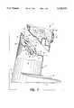
- FIG. 5is a cross-sectional view taken along lines 5--5 of FIG. 4;
- FIG. 6is a partial sectional view of the fan shown in FIG. 1 with a fan housing portion in a different operating position;
- FIG. 7is an exploded view illustrating a detent mechanism of the fan.
- a fan 11includes a housing 12 supported on a base 13 by a support member 14.
- the housing 12is fixed to the support member 14 so as to be movable therewith.
- Formed by the housing 12is a fan enclosure 16 that defines an inlet opening 17 covered by an inlet grill 18 and an outlet opening 21 covered by an outlet grill 22.
- a fan blade 24is mounted for rotation within the fan enclosure 16 to produce air flow between the inlet opening 17 and the outlet opening 21.
- an electric motor 25Operatively coupled to the fan blade 24 is an electric motor 25.
- the base 13includes a pedestal portion 28 having a bottom surface 29 for mounting on a suitable foundation such as a table or desk and an upwardly projecting upright portion 31 having vent openings 30 that communicate with the fan enclosure 16 through the support member 14.
- a cylindrical outer base surface 32having a non-circular cross-section in the form of an ellipse as shown in FIG. 5.
- the cylindrical upright portion 31is truncated at its upper end closed by a wall 33 forming an upwardly directed inclined coupling surface 35.
- Formed in the upwardly directed surface 35is an annular recess 36 having diametrically spaced apart opening 38, 39 and surrounding a central opening 41 illustrated in FIG. 7.
- the support member 14also is in the form of a truncated cylinder with an outer support surface 43 having a non-circular cross-section in the shape of an ellipse matching the ellipse formed by the upright portion 31. Longitudinally projecting portions of the outer support surface 43 have lengths uniformly varying between a minimum length portion 45 and a maximum length portion 46. Retained by the maximum length portion 46 is an electrical on-off switch 47 connected by control circuitry (not shown) to the electric motor 25.
- the lower end of the truncated cylindrical support member 14is closed by a wall 48 forming an inclined, downwardly directed, coupling surface 49 rotatably mounted on the upwardly directed coupling surface 25 of the base upright portion 31.
- the wall 48Defined by the wall 48 is an upwardly stepped portion 51 having an opening 52 and a downwardly stepped portion 53 received by the annular recess 36 in the upwardly directed coupling surface 35.
- a pair of internally threaded bosses 55project upwardly from the stepped portion 51 on opposite sides of the opening 52.
- Formed on a wafer 62is a base stop 58 (FIGS. 6 and 7) that engages a support stop 59 on a retainer 66: described hereinafter.
- the stops 58, 59limit rotation of the support member 14 on the base 13 to 360°. That prevents undesirable entanglement of electrical cords (not shown) retained within cavities formed in the upright portion 31 and the support member 14.
- the detent mechanism 61includes the first wafer rack gear member 62 having a central hole 63. Formed on a bottom surface of the wafer gear 62 are a plurality of annularly spaced apart gear teeth 64. Another component of the detent mechanism 61 is a retainer 66 having a cup-shaped central portion 65 and an outwardly directed flange portion 67 projecting radially outwardly from an open end thereof. Defined by the central portion 65 is a central opening 69 aligned with the hole 63 in the wafer 62 and the opening 41 in the coupling surface 35.
- a pair of gear teeth 72are formed in diametrically opposed positions on the annular flange 67 and project upwardly therefrom to engage the gear teeth 64 of the wafer gear 62.
- the gear wafer 62is sandwiched between a lower surface portion of the wall 33 and an upper surface of the flange portion 67 of the retainer 66. Screws (not shown) accommodated by the bosses 55 on the wall 48 and the bosses 71 on the cup shaped portion 65 to securely fix the retainer 66 to the support member 14.
- the wafer gear 62is fixed by means (not shown) to the wall 33 of the upright portion 31.
- the bottom surface 29 of the base 13is placed on a suitable foundation.
- the attached combination of the housing 12 and the support member 14then can be rotated on the upright portion 31 into a position wherein the rotating fan blade 24 produces air flow in a desired direction out of the outlet opening 21.
- the downwardly stepped portion 53 of the coupling surface 49rides in the annular seat formed by the annular recess 36 of the upwardly directed coupling surface 35.
- the rotary motionmoves the second gear teeth 72 of the retainer 66 into sequential engagement with the teeth 64 of the first gear 62 so as to establish stable, manually releaseable different rotational positions of a housing 12 on the upright member 31.
- the on-off switch 47 retained on the maximum length portion 46 of the outer support surface 43is directed upwardly so as to be readily accessible to a user.
- the outer support surface 43 of the support member 14 and the outer base surface 32 of the upright portion 31remain aligned in all operating positions so as to prevent undesirable displacements therebetween. Also air movement produced by the rotating fan blade 24 in response to energization of the electric motor 25 induces between the vent openings 30 and the outlet opening 21 of the housing 12 air flow that cools the motor 25.
Landscapes
- Engineering & Computer Science (AREA)
- Mechanical Engineering (AREA)
- General Engineering & Computer Science (AREA)
- Structures Of Non-Positive Displacement Pumps (AREA)
Abstract
Description
Claims (20)
Priority Applications (4)
| Application Number | Priority Date | Filing Date | Title |
|---|---|---|---|
| US08/415,917US5518370A (en) | 1995-04-03 | 1995-04-03 | Portable electric fan with swivel mount |
| CA002156094ACA2156094C (en) | 1995-04-03 | 1995-08-15 | Portable electric fan with swivel mount |
| EP95308973AEP0736693A1 (en) | 1995-04-03 | 1995-12-11 | Portable electric fan with swivel mount |
| JP7350206AJPH08277797A (en) | 1995-04-03 | 1995-12-22 | Portable type air-direction type electric fan |
Applications Claiming Priority (1)
| Application Number | Priority Date | Filing Date | Title |
|---|---|---|---|
| US08/415,917US5518370A (en) | 1995-04-03 | 1995-04-03 | Portable electric fan with swivel mount |
Publications (1)
| Publication Number | Publication Date |
|---|---|
| US5518370Atrue US5518370A (en) | 1996-05-21 |
Family
ID=23647763
Family Applications (1)
| Application Number | Title | Priority Date | Filing Date |
|---|---|---|---|
| US08/415,917Expired - Fee RelatedUS5518370A (en) | 1995-04-03 | 1995-04-03 | Portable electric fan with swivel mount |
Country Status (4)
| Country | Link |
|---|---|
| US (1) | US5518370A (en) |
| EP (1) | EP0736693A1 (en) |
| JP (1) | JPH08277797A (en) |
| CA (1) | CA2156094C (en) |
Cited By (83)
| Publication number | Priority date | Publication date | Assignee | Title |
|---|---|---|---|---|
| US5993417A (en)* | 1998-01-06 | 1999-11-30 | Yerfino; Daniel Alberto | Disposable syringe with an automatically retractable hypodermic needle |
| US6382865B1 (en) | 1999-06-21 | 2002-05-07 | Richard C. Paxman | Base-mounted lubricated ball joint |
| US6682308B1 (en) | 2002-08-01 | 2004-01-27 | Kaz, Inc. | Fan with adjustable mount |
| US7088913B1 (en) | 2004-06-28 | 2006-08-08 | Jcs/Thg, Llc | Baseboard/upright heater assembly |
| US20080069694A1 (en)* | 2006-09-19 | 2008-03-20 | Hector Ray Hernandez | Electric fan |
| US20080087315A1 (en)* | 2006-10-13 | 2008-04-17 | Aspen Systems, Inc. | Thermoelectric Fan for Radiation-Based Heaters, and Methods Related Thereto |
| US20090012003A1 (en)* | 1998-03-17 | 2009-01-08 | Genentech, Inc. | Polypeptides homologous to vegf and bmp1 |
| US20100096855A1 (en)* | 2007-04-25 | 2010-04-22 | Aerodyn Engineering Gmbh | Wind Power Plant |
| US20100226754A1 (en)* | 2009-03-04 | 2010-09-09 | Dyson Technology Limited | Fan assembly |
| US20100226753A1 (en)* | 2009-03-04 | 2010-09-09 | Dyson Technology Limited | Fan assembly |
| US20100226801A1 (en)* | 2009-03-04 | 2010-09-09 | Dyson Technology Limited | Fan assembly |
| US20100225012A1 (en)* | 2009-03-04 | 2010-09-09 | Dyson Technology Limited | Humidifying apparatus |
| US20100226787A1 (en)* | 2009-03-04 | 2010-09-09 | Dyson Technology Limited | Fan assembly |
| US20100226751A1 (en)* | 2009-03-04 | 2010-09-09 | Dyson Technology Limited | Fan assembly |
| US20100226763A1 (en)* | 2009-03-04 | 2010-09-09 | Dyson Technology Limited | Fan assembly |
| US20100226797A1 (en)* | 2009-03-04 | 2010-09-09 | Dyson Technology Limited | Fan assembly |
| US20100226750A1 (en)* | 2009-03-04 | 2010-09-09 | Dyson Technology Limited | Fan assembly |
| US20100226758A1 (en)* | 2009-03-04 | 2010-09-09 | Dyson Technology Limited | Fan assembly |
| US20100226749A1 (en)* | 2009-03-04 | 2010-09-09 | Dyson Technology Limited | Fan assembly |
| US20100226764A1 (en)* | 2009-03-04 | 2010-09-09 | Dyson Technology Limited | Fan |
| US20100226769A1 (en)* | 2009-03-04 | 2010-09-09 | Dyson Technology Limited | Fan assembly |
| US20100226752A1 (en)* | 2009-03-04 | 2010-09-09 | Dyson Technology Limited | Fan assembly |
| US20110058935A1 (en)* | 2007-09-04 | 2011-03-10 | Dyson Technology Limited | Fan |
| US20110110805A1 (en)* | 2009-11-06 | 2011-05-12 | Dyson Technology Limited | Fan |
| US20110164959A1 (en)* | 2008-09-23 | 2011-07-07 | Dyson Technology Limited | Fan |
| US20110223014A1 (en)* | 2009-03-04 | 2011-09-15 | Dyson Technology Limited | Fan assembly |
| US20110236229A1 (en)* | 2010-03-23 | 2011-09-29 | Dyson Technology Limited | Accessory for a fan |
| US20120014785A1 (en)* | 2010-07-14 | 2012-01-19 | Hsin-Hong Chen | Structure of circulation fan |
| US8366403B2 (en) | 2010-08-06 | 2013-02-05 | Dyson Technology Limited | Fan assembly |
| AU2013100647B4 (en)* | 2010-05-27 | 2013-09-12 | Dyson Technology Limited | Device for blowing air by means of narrow slit nozzle assembly |
| AU2011257733B2 (en)* | 2010-05-27 | 2013-11-21 | Dyson Technology Limited | Device for blowing air by means of narrow slit nozzle assembly |
| US8734094B2 (en) | 2010-08-06 | 2014-05-27 | Dyson Technology Limited | Fan assembly |
| US8873940B2 (en) | 2010-08-06 | 2014-10-28 | Dyson Technology Limited | Fan assembly |
| US8882451B2 (en) | 2010-03-23 | 2014-11-11 | Dyson Technology Limited | Fan |
| US8894354B2 (en) | 2010-09-07 | 2014-11-25 | Dyson Technology Limited | Fan |
| US8967979B2 (en) | 2010-10-18 | 2015-03-03 | Dyson Technology Limited | Fan assembly |
| US8967980B2 (en) | 2010-10-18 | 2015-03-03 | Dyson Technology Limited | Fan assembly |
| USD728092S1 (en) | 2013-08-01 | 2015-04-28 | Dyson Technology Limited | Fan |
| USD728769S1 (en) | 2013-08-01 | 2015-05-05 | Dyson Technology Limited | Fan |
| USD728770S1 (en) | 2013-08-01 | 2015-05-05 | Dyson Technology Limited | Fan |
| USD729375S1 (en) | 2013-03-07 | 2015-05-12 | Dyson Technology Limited | Fan |
| USD729373S1 (en) | 2013-03-07 | 2015-05-12 | Dyson Technology Limited | Fan |
| USD729376S1 (en) | 2013-03-07 | 2015-05-12 | Dyson Technology Limited | Fan |
| USD729374S1 (en) | 2013-03-07 | 2015-05-12 | Dyson Technology Limited | Fan |
| USD729372S1 (en) | 2013-03-07 | 2015-05-12 | Dyson Technology Limited | Fan |
| USD729925S1 (en) | 2013-03-07 | 2015-05-19 | Dyson Technology Limited | Fan |
| US9127855B2 (en) | 2011-07-27 | 2015-09-08 | Dyson Technology Limited | Fan assembly |
| US9151299B2 (en) | 2012-02-06 | 2015-10-06 | Dyson Technology Limited | Fan |
| USD746425S1 (en) | 2013-01-18 | 2015-12-29 | Dyson Technology Limited | Humidifier |
| USD746966S1 (en) | 2013-01-18 | 2016-01-05 | Dyson Technology Limited | Humidifier |
| USD747450S1 (en) | 2013-01-18 | 2016-01-12 | Dyson Technology Limited | Humidifier |
| US9249809B2 (en) | 2012-02-06 | 2016-02-02 | Dyson Technology Limited | Fan |
| USD749231S1 (en) | 2013-01-18 | 2016-02-09 | Dyson Technology Limited | Humidifier |
| US9283573B2 (en) | 2012-02-06 | 2016-03-15 | Dyson Technology Limited | Fan assembly |
| US9328739B2 (en) | 2012-01-19 | 2016-05-03 | Dyson Technology Limited | Fan |
| US9366449B2 (en) | 2012-03-06 | 2016-06-14 | Dyson Technology Limited | Humidifying apparatus |
| US9410711B2 (en) | 2013-09-26 | 2016-08-09 | Dyson Technology Limited | Fan assembly |
| US9458853B2 (en) | 2011-07-27 | 2016-10-04 | Dyson Technology Limited | Fan assembly |
| US9568021B2 (en) | 2012-05-16 | 2017-02-14 | Dyson Technology Limited | Fan |
| US9568006B2 (en) | 2012-05-16 | 2017-02-14 | Dyson Technology Limited | Fan |
| US9599356B2 (en) | 2014-07-29 | 2017-03-21 | Dyson Technology Limited | Humidifying apparatus |
| US9677565B1 (en) | 2013-11-18 | 2017-06-13 | Michael W. Rodriguez | Hand crank-powered fan |
| US9732763B2 (en) | 2012-07-11 | 2017-08-15 | Dyson Technology Limited | Fan assembly |
| US9745996B2 (en) | 2010-12-02 | 2017-08-29 | Dyson Technology Limited | Fan |
| US9745981B2 (en) | 2011-11-11 | 2017-08-29 | Dyson Technology Limited | Fan assembly |
| US9752789B2 (en) | 2012-03-06 | 2017-09-05 | Dyson Technology Limited | Humidifying apparatus |
| US9797612B2 (en) | 2013-01-29 | 2017-10-24 | Dyson Technology Limited | Fan assembly |
| US9797613B2 (en) | 2012-03-06 | 2017-10-24 | Dyson Technology Limited | Humidifying apparatus |
| US9797414B2 (en) | 2013-07-09 | 2017-10-24 | Dyson Technology Limited | Fan assembly |
| US9816531B2 (en) | 2008-10-25 | 2017-11-14 | Dyson Technology Limited | Fan utilizing coanda surface |
| US9822778B2 (en) | 2012-04-19 | 2017-11-21 | Dyson Technology Limited | Fan assembly |
| US9903602B2 (en) | 2014-07-29 | 2018-02-27 | Dyson Technology Limited | Humidifying apparatus |
| US9927136B2 (en) | 2012-03-06 | 2018-03-27 | Dyson Technology Limited | Fan assembly |
| US9926804B2 (en) | 2010-11-02 | 2018-03-27 | Dyson Technology Limited | Fan assembly |
| US9982677B2 (en) | 2014-07-29 | 2018-05-29 | Dyson Technology Limited | Fan assembly |
| US10094392B2 (en) | 2011-11-24 | 2018-10-09 | Dyson Technology Limited | Fan assembly |
| US10100836B2 (en) | 2010-10-13 | 2018-10-16 | Dyson Technology Limited | Fan assembly |
| US10145583B2 (en) | 2012-04-04 | 2018-12-04 | Dyson Technology Limited | Heating apparatus |
| US10408478B2 (en) | 2012-03-06 | 2019-09-10 | Dyson Technology Limited | Humidifying apparatus |
| US10428837B2 (en) | 2012-05-16 | 2019-10-01 | Dyson Technology Limited | Fan |
| US10465928B2 (en) | 2012-03-06 | 2019-11-05 | Dyson Technology Limited | Humidifying apparatus |
| US10612565B2 (en) | 2013-01-29 | 2020-04-07 | Dyson Technology Limited | Fan assembly |
| US11378100B2 (en) | 2020-11-30 | 2022-07-05 | E. Mishan & Sons, Inc. | Oscillating portable fan with removable grille |
Citations (3)
| Publication number | Priority date | Publication date | Assignee | Title |
|---|---|---|---|---|
| US3591309A (en)* | 1969-06-30 | 1971-07-06 | Beckman Instruments Inc | Mixer and filter combination for discrete simple containers |
| JPS60197767A (en)* | 1984-03-21 | 1985-10-07 | Mitsui Toatsu Chem Inc | Coating material for heat-resistant precoated metal |
| US5429481A (en)* | 1994-08-24 | 1995-07-04 | Liu; Su-Liang | Angle-adjustable joint for electric fans |
Family Cites Families (6)
| Publication number | Priority date | Publication date | Assignee | Title |
|---|---|---|---|---|
| DE7328317U (en)* | 1975-01-30 | Siemens Ag | Downdraft extractor | |
| US1635768A (en)* | 1924-05-17 | 1927-07-12 | Rodgers Dominick | Fan |
| US2395167A (en)* | 1944-10-18 | 1946-02-19 | Torrington Mfg Co | Electric fan assembly |
| DE1095452B (en)* | 1957-12-09 | 1960-12-22 | Licentia Gmbh | Table fan |
| US4457672A (en)* | 1981-03-23 | 1984-07-03 | Mitsubishi Denki Kabushiki Kaisha | Fan with variable axis impeller |
| US5018951A (en)* | 1989-08-09 | 1991-05-28 | Duracraft Corporation | Portable electrical fan |
- 1995
- 1995-04-03USUS08/415,917patent/US5518370A/ennot_activeExpired - Fee Related
- 1995-08-15CACA002156094Apatent/CA2156094C/ennot_activeExpired - Fee Related
- 1995-12-11EPEP95308973Apatent/EP0736693A1/ennot_activeWithdrawn
- 1995-12-22JPJP7350206Apatent/JPH08277797A/enactivePending
Patent Citations (3)
| Publication number | Priority date | Publication date | Assignee | Title |
|---|---|---|---|---|
| US3591309A (en)* | 1969-06-30 | 1971-07-06 | Beckman Instruments Inc | Mixer and filter combination for discrete simple containers |
| JPS60197767A (en)* | 1984-03-21 | 1985-10-07 | Mitsui Toatsu Chem Inc | Coating material for heat-resistant precoated metal |
| US5429481A (en)* | 1994-08-24 | 1995-07-04 | Liu; Su-Liang | Angle-adjustable joint for electric fans |
Cited By (134)
| Publication number | Priority date | Publication date | Assignee | Title |
|---|---|---|---|---|
| US5993417A (en)* | 1998-01-06 | 1999-11-30 | Yerfino; Daniel Alberto | Disposable syringe with an automatically retractable hypodermic needle |
| US20090012003A1 (en)* | 1998-03-17 | 2009-01-08 | Genentech, Inc. | Polypeptides homologous to vegf and bmp1 |
| US20090264370A9 (en)* | 1998-03-17 | 2009-10-22 | Genentech, Inc. | Polypeptides homologous to vegf and bmp1 |
| US6382865B1 (en) | 1999-06-21 | 2002-05-07 | Richard C. Paxman | Base-mounted lubricated ball joint |
| US6682308B1 (en) | 2002-08-01 | 2004-01-27 | Kaz, Inc. | Fan with adjustable mount |
| US7088913B1 (en) | 2004-06-28 | 2006-08-08 | Jcs/Thg, Llc | Baseboard/upright heater assembly |
| US20080069694A1 (en)* | 2006-09-19 | 2008-03-20 | Hector Ray Hernandez | Electric fan |
| US20080087315A1 (en)* | 2006-10-13 | 2008-04-17 | Aspen Systems, Inc. | Thermoelectric Fan for Radiation-Based Heaters, and Methods Related Thereto |
| US20100096855A1 (en)* | 2007-04-25 | 2010-04-22 | Aerodyn Engineering Gmbh | Wind Power Plant |
| US8426993B2 (en)* | 2007-04-25 | 2013-04-23 | Aerodyn Engineering Gmbh | Wind power plant |
| US20110058935A1 (en)* | 2007-09-04 | 2011-03-10 | Dyson Technology Limited | Fan |
| US9249810B2 (en) | 2007-09-04 | 2016-02-02 | Dyson Technology Limited | Fan |
| US8764412B2 (en) | 2007-09-04 | 2014-07-01 | Dyson Technology Limited | Fan |
| US8403650B2 (en) | 2007-09-04 | 2013-03-26 | Dyson Technology Limited | Fan |
| US8348629B2 (en) | 2008-09-23 | 2013-01-08 | Dyston Technology Limited | Fan |
| US20110164959A1 (en)* | 2008-09-23 | 2011-07-07 | Dyson Technology Limited | Fan |
| US9816531B2 (en) | 2008-10-25 | 2017-11-14 | Dyson Technology Limited | Fan utilizing coanda surface |
| US10145388B2 (en) | 2008-10-25 | 2018-12-04 | Dyson Technology Limited | Fan with a filter |
| CN102493960A (en)* | 2009-03-04 | 2012-06-13 | 戴森技术有限公司 | A fan assembly |
| US8403640B2 (en) | 2009-03-04 | 2013-03-26 | Dyson Technology Limited | Fan assembly |
| US20100226764A1 (en)* | 2009-03-04 | 2010-09-09 | Dyson Technology Limited | Fan |
| US20100226769A1 (en)* | 2009-03-04 | 2010-09-09 | Dyson Technology Limited | Fan assembly |
| US20100226752A1 (en)* | 2009-03-04 | 2010-09-09 | Dyson Technology Limited | Fan assembly |
| US20100226758A1 (en)* | 2009-03-04 | 2010-09-09 | Dyson Technology Limited | Fan assembly |
| US20100226754A1 (en)* | 2009-03-04 | 2010-09-09 | Dyson Technology Limited | Fan assembly |
| US20100226750A1 (en)* | 2009-03-04 | 2010-09-09 | Dyson Technology Limited | Fan assembly |
| AU2011100444B4 (en)* | 2009-03-04 | 2011-08-11 | Dyson Technology Limited | A fan assembly |
| AU2011100445B4 (en)* | 2009-03-04 | 2011-08-11 | Dyson Technology Limited | A fan assembly |
| US20110223014A1 (en)* | 2009-03-04 | 2011-09-15 | Dyson Technology Limited | Fan assembly |
| US10221860B2 (en) | 2009-03-04 | 2019-03-05 | Dyson Technology Limited | Fan assembly |
| US8052379B2 (en) | 2009-03-04 | 2011-11-08 | Dyson Technology Limited | Fan assembly |
| US20100226797A1 (en)* | 2009-03-04 | 2010-09-09 | Dyson Technology Limited | Fan assembly |
| CN102425575A (en)* | 2009-03-04 | 2012-04-25 | 戴森技术有限公司 | Fan assembly |
| US8197226B2 (en) | 2009-03-04 | 2012-06-12 | Dyson Technology Limited | Fan assembly |
| US8932028B2 (en) | 2009-03-04 | 2015-01-13 | Dyson Technology Limited | Fan assembly |
| US8246317B2 (en) | 2009-03-04 | 2012-08-21 | Dyson Technology Limited | Fan assembly |
| US8308432B2 (en) | 2009-03-04 | 2012-11-13 | Dyson Technology Limited | Fan assembly |
| US8348597B2 (en) | 2009-03-04 | 2013-01-08 | Dyson Technology Limited | Fan assembly |
| US8348596B2 (en) | 2009-03-04 | 2013-01-08 | Dyson Technology Limited | Fan assembly |
| US20100226763A1 (en)* | 2009-03-04 | 2010-09-09 | Dyson Technology Limited | Fan assembly |
| US8356804B2 (en) | 2009-03-04 | 2013-01-22 | Dyson Technology Limited | Humidifying apparatus |
| US10006657B2 (en) | 2009-03-04 | 2018-06-26 | Dyson Technology Limited | Fan assembly |
| US20100226751A1 (en)* | 2009-03-04 | 2010-09-09 | Dyson Technology Limited | Fan assembly |
| US20100226749A1 (en)* | 2009-03-04 | 2010-09-09 | Dyson Technology Limited | Fan assembly |
| US8408869B2 (en) | 2009-03-04 | 2013-04-02 | Dyson Technology Limited | Fan assembly |
| US20100226787A1 (en)* | 2009-03-04 | 2010-09-09 | Dyson Technology Limited | Fan assembly |
| US8430624B2 (en) | 2009-03-04 | 2013-04-30 | Dyson Technology Limited | Fan assembly |
| US9127689B2 (en) | 2009-03-04 | 2015-09-08 | Dyson Technology Limited | Fan assembly |
| US8469660B2 (en) | 2009-03-04 | 2013-06-25 | Dyson Technology Limited | Fan assembly |
| US8469658B2 (en) | 2009-03-04 | 2013-06-25 | Dyson Technology Limited | Fan |
| US8469655B2 (en) | 2009-03-04 | 2013-06-25 | Dyson Technology Limited | Fan assembly |
| US8529203B2 (en) | 2009-03-04 | 2013-09-10 | Dyson Technology Limited | Fan assembly |
| US20100225012A1 (en)* | 2009-03-04 | 2010-09-09 | Dyson Technology Limited | Humidifying apparatus |
| US9599368B2 (en) | 2009-03-04 | 2017-03-21 | Dyson Technology Limited | Nozzle for bladeless fan assembly with heater |
| US8613601B2 (en) | 2009-03-04 | 2013-12-24 | Dyson Technology Limited | Fan assembly |
| US8684687B2 (en) | 2009-03-04 | 2014-04-01 | Dyson Technology Limited | Fan assembly |
| US8708650B2 (en) | 2009-03-04 | 2014-04-29 | Dyson Technology Limited | Fan assembly |
| US8714937B2 (en) | 2009-03-04 | 2014-05-06 | Dyson Technology Limited | Fan assembly |
| US8721286B2 (en) | 2009-03-04 | 2014-05-13 | Dyson Technology Limited | Fan assembly |
| US9513028B2 (en)* | 2009-03-04 | 2016-12-06 | Dyson Technology Limited | Fan assembly |
| US20100226801A1 (en)* | 2009-03-04 | 2010-09-09 | Dyson Technology Limited | Fan assembly |
| US20100226753A1 (en)* | 2009-03-04 | 2010-09-09 | Dyson Technology Limited | Fan assembly |
| US8784071B2 (en) | 2009-03-04 | 2014-07-22 | Dyson Technology Limited | Fan assembly |
| US8783663B2 (en) | 2009-03-04 | 2014-07-22 | Dyson Technology Limited | Humidifying apparatus |
| US8784049B2 (en) | 2009-03-04 | 2014-07-22 | Dyson Technology Limited | Fan |
| CN102493960B (en)* | 2009-03-04 | 2014-09-10 | 戴森技术有限公司 | A fan assembly |
| US8454322B2 (en) | 2009-11-06 | 2013-06-04 | Dyson Technology Limited | Fan having a magnetically attached remote control |
| US20110110805A1 (en)* | 2009-11-06 | 2011-05-12 | Dyson Technology Limited | Fan |
| US9004878B2 (en) | 2009-11-06 | 2015-04-14 | Dyson Technology Limited | Fan having a magnetically attached remote control |
| US8882451B2 (en) | 2010-03-23 | 2014-11-11 | Dyson Technology Limited | Fan |
| US8770946B2 (en) | 2010-03-23 | 2014-07-08 | Dyson Technology Limited | Accessory for a fan |
| US20110236229A1 (en)* | 2010-03-23 | 2011-09-29 | Dyson Technology Limited | Accessory for a fan |
| AU2011257733B2 (en)* | 2010-05-27 | 2013-11-21 | Dyson Technology Limited | Device for blowing air by means of narrow slit nozzle assembly |
| AU2013100647B4 (en)* | 2010-05-27 | 2013-09-12 | Dyson Technology Limited | Device for blowing air by means of narrow slit nozzle assembly |
| US9011116B2 (en) | 2010-05-27 | 2015-04-21 | Dyson Technology Limited | Device for blowing air by means of a nozzle assembly |
| US20120014785A1 (en)* | 2010-07-14 | 2012-01-19 | Hsin-Hong Chen | Structure of circulation fan |
| US8734094B2 (en) | 2010-08-06 | 2014-05-27 | Dyson Technology Limited | Fan assembly |
| US8366403B2 (en) | 2010-08-06 | 2013-02-05 | Dyson Technology Limited | Fan assembly |
| US10344773B2 (en) | 2010-08-06 | 2019-07-09 | Dyson Technology Limited | Fan assembly |
| US8873940B2 (en) | 2010-08-06 | 2014-10-28 | Dyson Technology Limited | Fan assembly |
| US9745988B2 (en) | 2010-09-07 | 2017-08-29 | Dyson Technology Limited | Fan |
| US8894354B2 (en) | 2010-09-07 | 2014-11-25 | Dyson Technology Limited | Fan |
| US10100836B2 (en) | 2010-10-13 | 2018-10-16 | Dyson Technology Limited | Fan assembly |
| US8967980B2 (en) | 2010-10-18 | 2015-03-03 | Dyson Technology Limited | Fan assembly |
| US8967979B2 (en) | 2010-10-18 | 2015-03-03 | Dyson Technology Limited | Fan assembly |
| US9926804B2 (en) | 2010-11-02 | 2018-03-27 | Dyson Technology Limited | Fan assembly |
| US9745996B2 (en) | 2010-12-02 | 2017-08-29 | Dyson Technology Limited | Fan |
| US9291361B2 (en) | 2011-07-27 | 2016-03-22 | Dyson Technology Limited | Fan assembly |
| US9335064B2 (en) | 2011-07-27 | 2016-05-10 | Dyson Technology Limited | Fan assembly |
| US10094581B2 (en) | 2011-07-27 | 2018-10-09 | Dyson Technology Limited | Fan assembly |
| US9127855B2 (en) | 2011-07-27 | 2015-09-08 | Dyson Technology Limited | Fan assembly |
| US9458853B2 (en) | 2011-07-27 | 2016-10-04 | Dyson Technology Limited | Fan assembly |
| US9745981B2 (en) | 2011-11-11 | 2017-08-29 | Dyson Technology Limited | Fan assembly |
| US10094392B2 (en) | 2011-11-24 | 2018-10-09 | Dyson Technology Limited | Fan assembly |
| US9328739B2 (en) | 2012-01-19 | 2016-05-03 | Dyson Technology Limited | Fan |
| US9283573B2 (en) | 2012-02-06 | 2016-03-15 | Dyson Technology Limited | Fan assembly |
| US9151299B2 (en) | 2012-02-06 | 2015-10-06 | Dyson Technology Limited | Fan |
| US9249809B2 (en) | 2012-02-06 | 2016-02-02 | Dyson Technology Limited | Fan |
| US9366449B2 (en) | 2012-03-06 | 2016-06-14 | Dyson Technology Limited | Humidifying apparatus |
| US10465928B2 (en) | 2012-03-06 | 2019-11-05 | Dyson Technology Limited | Humidifying apparatus |
| US10563875B2 (en) | 2012-03-06 | 2020-02-18 | Dyson Technology Limited | Humidifying apparatus |
| US9927136B2 (en) | 2012-03-06 | 2018-03-27 | Dyson Technology Limited | Fan assembly |
| US10408478B2 (en) | 2012-03-06 | 2019-09-10 | Dyson Technology Limited | Humidifying apparatus |
| US9797613B2 (en) | 2012-03-06 | 2017-10-24 | Dyson Technology Limited | Humidifying apparatus |
| US9752789B2 (en) | 2012-03-06 | 2017-09-05 | Dyson Technology Limited | Humidifying apparatus |
| US10145583B2 (en) | 2012-04-04 | 2018-12-04 | Dyson Technology Limited | Heating apparatus |
| US9822778B2 (en) | 2012-04-19 | 2017-11-21 | Dyson Technology Limited | Fan assembly |
| US9568006B2 (en) | 2012-05-16 | 2017-02-14 | Dyson Technology Limited | Fan |
| US9568021B2 (en) | 2012-05-16 | 2017-02-14 | Dyson Technology Limited | Fan |
| US10428837B2 (en) | 2012-05-16 | 2019-10-01 | Dyson Technology Limited | Fan |
| US10309420B2 (en) | 2012-05-16 | 2019-06-04 | Dyson Technology Limited | Fan |
| US9732763B2 (en) | 2012-07-11 | 2017-08-15 | Dyson Technology Limited | Fan assembly |
| USD746425S1 (en) | 2013-01-18 | 2015-12-29 | Dyson Technology Limited | Humidifier |
| USD749231S1 (en) | 2013-01-18 | 2016-02-09 | Dyson Technology Limited | Humidifier |
| USD747450S1 (en) | 2013-01-18 | 2016-01-12 | Dyson Technology Limited | Humidifier |
| USD746966S1 (en) | 2013-01-18 | 2016-01-05 | Dyson Technology Limited | Humidifier |
| US10612565B2 (en) | 2013-01-29 | 2020-04-07 | Dyson Technology Limited | Fan assembly |
| US9797612B2 (en) | 2013-01-29 | 2017-10-24 | Dyson Technology Limited | Fan assembly |
| USD729373S1 (en) | 2013-03-07 | 2015-05-12 | Dyson Technology Limited | Fan |
| USD729375S1 (en) | 2013-03-07 | 2015-05-12 | Dyson Technology Limited | Fan |
| USD729925S1 (en) | 2013-03-07 | 2015-05-19 | Dyson Technology Limited | Fan |
| USD729372S1 (en) | 2013-03-07 | 2015-05-12 | Dyson Technology Limited | Fan |
| USD729374S1 (en) | 2013-03-07 | 2015-05-12 | Dyson Technology Limited | Fan |
| USD729376S1 (en) | 2013-03-07 | 2015-05-12 | Dyson Technology Limited | Fan |
| US9797414B2 (en) | 2013-07-09 | 2017-10-24 | Dyson Technology Limited | Fan assembly |
| USD728770S1 (en) | 2013-08-01 | 2015-05-05 | Dyson Technology Limited | Fan |
| USD728769S1 (en) | 2013-08-01 | 2015-05-05 | Dyson Technology Limited | Fan |
| USD728092S1 (en) | 2013-08-01 | 2015-04-28 | Dyson Technology Limited | Fan |
| US9410711B2 (en) | 2013-09-26 | 2016-08-09 | Dyson Technology Limited | Fan assembly |
| US9677565B1 (en) | 2013-11-18 | 2017-06-13 | Michael W. Rodriguez | Hand crank-powered fan |
| US9599356B2 (en) | 2014-07-29 | 2017-03-21 | Dyson Technology Limited | Humidifying apparatus |
| US9982677B2 (en) | 2014-07-29 | 2018-05-29 | Dyson Technology Limited | Fan assembly |
| US9903602B2 (en) | 2014-07-29 | 2018-02-27 | Dyson Technology Limited | Humidifying apparatus |
| US11378100B2 (en) | 2020-11-30 | 2022-07-05 | E. Mishan & Sons, Inc. | Oscillating portable fan with removable grille |
Also Published As
| Publication number | Publication date |
|---|---|
| JPH08277797A (en) | 1996-10-22 |
| CA2156094C (en) | 2002-08-13 |
| EP0736693A1 (en) | 1996-10-09 |
| CA2156094A1 (en) | 1996-10-04 |
Similar Documents
| Publication | Publication Date | Title |
|---|---|---|
| US5518370A (en) | Portable electric fan with swivel mount | |
| US5304040A (en) | Tri-pod portable fan | |
| US5547343A (en) | Table fan with vise clamp | |
| US4457672A (en) | Fan with variable axis impeller | |
| US5273358A (en) | Quiet and efficient motor cooling fan assembly for a blender | |
| US6953278B2 (en) | Mixing machine with accessible internal control unit | |
| US20050123392A1 (en) | Multi-directional tower fan | |
| CA2360344C (en) | Pivotable heater | |
| CN110374903B (en) | Floor folding fan | |
| CA2022525C (en) | Portable electrical fan | |
| US5411373A (en) | Convertible floor fan | |
| US3493214A (en) | Electric blender | |
| US6244823B1 (en) | Dual positionable oscillating fan | |
| JPS62164408A (en) | Air outlet assembly of dryer | |
| CN111059487A (en) | A professional desk lamp | |
| WO2022083519A1 (en) | Neck fan | |
| JPS6160999B2 (en) | ||
| CN221347351U (en) | Dual-purpose small fan capable of being hung on wall and used vertically | |
| US6476334B1 (en) | Switch box structure of a ceiling fan | |
| US12359678B1 (en) | Ceiling fan | |
| CN222879928U (en) | Fan with adjustable angle | |
| CN217462628U (en) | Fan with cooling device | |
| CN212226510U (en) | Rotatory every single move platform of camera | |
| CN222584233U (en) | Pot assembly and automatic cooking device | |
| CN222880739U (en) | Equipment support |
Legal Events
| Date | Code | Title | Description |
|---|---|---|---|
| AS | Assignment | Owner name:DURACRAFT CORPORATION, MASSACHUSETTS Free format text:ASSIGNMENT OF ASSIGNORS INTEREST;ASSIGNORS:WANG, JUI-SHANG;JANE, RODNEY;LONGAN, JOHN;REEL/FRAME:007487/0387 Effective date:19950505 | |
| FP | Expired due to failure to pay maintenance fee | Effective date:19961030 | |
| AS | Assignment | Owner name:HONEYWELL CONSUMER PRODUCTS, INC., MASSACHUSETTS Free format text:CHANGE OF NAME;ASSIGNOR:DURACRAFT CORPORATION;REEL/FRAME:008854/0440 Effective date:19961121 | |
| FPAY | Fee payment | Year of fee payment:4 | |
| AS | Assignment | Owner name:KAZ HOME ENVIRONMENT, INC., MASSACHUSETTS Free format text:CHANGE OF NAME;ASSIGNOR:HONEYWELL CONSUMER PRODUCTS, INC.;REEL/FRAME:013897/0758 Effective date:20020827 Owner name:KAZ, INC., NEW YORK Free format text:ASSIGNMENT OF ASSIGNORS INTEREST;ASSIGNOR:KAZ HOME ENVIRONMENT, INC.;REEL/FRAME:013868/0187 Effective date:20030328 | |
| FPAY | Fee payment | Year of fee payment:8 | |
| AS | Assignment | Owner name:BANK OF AMERICA, N.A., AS AGENT, MASSACHUSETTS Free format text:SECURITY AGREEMENT;ASSIGNORS:KAZ, INC.;KAZ USA, INC.;KAZ CANADA, INC.;REEL/FRAME:017215/0696 Effective date:20060131 | |
| REMI | Maintenance fee reminder mailed | ||
| LAPS | Lapse for failure to pay maintenance fees | ||
| STCH | Information on status: patent discontinuation | Free format text:PATENT EXPIRED DUE TO NONPAYMENT OF MAINTENANCE FEES UNDER 37 CFR 1.362 | |
| FP | Expired due to failure to pay maintenance fee | Effective date:20080521 |