US5518276A - Quick connector with pull back verification method - Google Patents
Quick connector with pull back verification methodDownload PDFInfo
- Publication number
- US5518276A US5518276AUS08/308,087US30808794AUS5518276AUS 5518276 AUS5518276 AUS 5518276AUS 30808794 AUS30808794 AUS 30808794AUS 5518276 AUS5518276 AUS 5518276A
- Authority
- US
- United States
- Prior art keywords
- legs
- male member
- connector body
- bore
- verification
- Prior art date
- Legal status (The legal status is an assumption and is not a legal conclusion. Google has not performed a legal analysis and makes no representation as to the accuracy of the status listed.)
- Expired - Lifetime
Links
- 238000012795verificationMethods0.000titleclaimsabstractdescription47
- 238000000034methodMethods0.000titleclaimsdescription14
- 230000008878couplingEffects0.000claimsabstractdescription44
- 238000010168coupling processMethods0.000claimsabstractdescription44
- 238000005859coupling reactionMethods0.000claimsabstractdescription44
- 239000012530fluidSubstances0.000claimsabstractdescription21
- 230000014759maintenance of locationEffects0.000claimsabstractdescription18
- 230000000007visual effectEffects0.000claimsabstractdescription11
- 238000003780insertionMethods0.000description9
- 230000037431insertionEffects0.000description9
- 125000006850spacer groupChemical group0.000description9
- 229920001973fluoroelastomerPolymers0.000description4
- 230000007246mechanismEffects0.000description4
- 230000008569processEffects0.000description4
- 238000004891communicationMethods0.000description3
- 239000002184metalSubstances0.000description3
- 230000000717retained effectEffects0.000description3
- 229920002449FKMPolymers0.000description2
- JHWNWJKBPDFINM-UHFFFAOYSA-NLaurolactamChemical compoundO=C1CCCCCCCCCCCN1JHWNWJKBPDFINM-UHFFFAOYSA-N0.000description2
- 229920000299Nylon 12Polymers0.000description2
- 238000001514detection methodMethods0.000description2
- 238000006073displacement reactionMethods0.000description2
- 239000011521glassSubstances0.000description2
- 238000009434installationMethods0.000description2
- 230000036961partial effectEffects0.000description2
- 230000002829reductive effectEffects0.000description2
- 229910001220stainless steelInorganic materials0.000description2
- 239000010935stainless steelSubstances0.000description2
- YCKRFDGAMUMZLT-UHFFFAOYSA-NFluorine atomChemical compound[F]YCKRFDGAMUMZLT-UHFFFAOYSA-N0.000description1
- 244000208734Pisonia aculeataSpecies0.000description1
- 230000015556catabolic processEffects0.000description1
- 230000008859changeEffects0.000description1
- 238000005520cutting processMethods0.000description1
- 230000003247decreasing effectEffects0.000description1
- 230000002950deficientEffects0.000description1
- 230000000694effectsEffects0.000description1
- 229910052731fluorineInorganic materials0.000description1
- 239000011737fluorineSubstances0.000description1
- 230000006870functionEffects0.000description1
- 238000004519manufacturing processMethods0.000description1
- 239000007769metal materialSubstances0.000description1
- 239000000203mixtureSubstances0.000description1
- 230000004048modificationEffects0.000description1
- 238000012986modificationMethods0.000description1
- 238000000053physical methodMethods0.000description1
- 229920003023plasticPolymers0.000description1
- 238000003825pressingMethods0.000description1
- 230000004044responseEffects0.000description1
- 230000002441reversible effectEffects0.000description1
- 238000007789sealingMethods0.000description1
- 239000007787solidSubstances0.000description1
Images


Classifications
- F—MECHANICAL ENGINEERING; LIGHTING; HEATING; WEAPONS; BLASTING
- F16—ENGINEERING ELEMENTS AND UNITS; GENERAL MEASURES FOR PRODUCING AND MAINTAINING EFFECTIVE FUNCTIONING OF MACHINES OR INSTALLATIONS; THERMAL INSULATION IN GENERAL
- F16L—PIPES; JOINTS OR FITTINGS FOR PIPES; SUPPORTS FOR PIPES, CABLES OR PROTECTIVE TUBING; MEANS FOR THERMAL INSULATION IN GENERAL
- F16L37/00—Couplings of the quick-acting type
- F16L37/08—Couplings of the quick-acting type in which the connection between abutting or axially overlapping ends is maintained by locking members
- F16L37/084—Couplings of the quick-acting type in which the connection between abutting or axially overlapping ends is maintained by locking members combined with automatic locking
- F16L37/098—Couplings of the quick-acting type in which the connection between abutting or axially overlapping ends is maintained by locking members combined with automatic locking by means of flexible hooks
- F16L37/0985—Couplings of the quick-acting type in which the connection between abutting or axially overlapping ends is maintained by locking members combined with automatic locking by means of flexible hooks the flexible hook extending radially inwardly from an outer part and engaging a bead, recess or the like on an inner part
- F16L37/0987—Couplings of the quick-acting type in which the connection between abutting or axially overlapping ends is maintained by locking members combined with automatic locking by means of flexible hooks the flexible hook extending radially inwardly from an outer part and engaging a bead, recess or the like on an inner part the flexible hook being progressively compressed by axial tensile loads acting on the coupling
- F—MECHANICAL ENGINEERING; LIGHTING; HEATING; WEAPONS; BLASTING
- F16—ENGINEERING ELEMENTS AND UNITS; GENERAL MEASURES FOR PRODUCING AND MAINTAINING EFFECTIVE FUNCTIONING OF MACHINES OR INSTALLATIONS; THERMAL INSULATION IN GENERAL
- F16L—PIPES; JOINTS OR FITTINGS FOR PIPES; SUPPORTS FOR PIPES, CABLES OR PROTECTIVE TUBING; MEANS FOR THERMAL INSULATION IN GENERAL
- F16L2201/00—Special arrangements for pipe couplings
- F16L2201/10—Indicators for correct coupling
- Y—GENERAL TAGGING OF NEW TECHNOLOGICAL DEVELOPMENTS; GENERAL TAGGING OF CROSS-SECTIONAL TECHNOLOGIES SPANNING OVER SEVERAL SECTIONS OF THE IPC; TECHNICAL SUBJECTS COVERED BY FORMER USPC CROSS-REFERENCE ART COLLECTIONS [XRACs] AND DIGESTS
- Y10—TECHNICAL SUBJECTS COVERED BY FORMER USPC
- Y10S—TECHNICAL SUBJECTS COVERED BY FORMER USPC CROSS-REFERENCE ART COLLECTIONS [XRACs] AND DIGESTS
- Y10S285/00—Pipe joints or couplings
- Y10S285/921—Snap-fit
Definitions
- This inventionrelates to fluid line systems which include quick connector couplings, and more particularly to a quick connector coupling having means to visually indicate whether a proper connection has been made between the male and female portions of the quick connector.
- quick connector couplingsare often utilized to provide a fluid connection between two components or conduits, thus establishing a fluid line between the two components, usually a rigid tube and a system element contained within a metal housing.
- Use of quick connector couplingsis advantageous in that a sufficiently sealed and secured fluid line may be established with a minimum amount of time and expense.
- Audible verification of a proper connectionis sometimes possible.
- an audible "click”is heard when the male member locks into place.
- the clickresults from resilient arms of a retainer contained within the female connector body snapping into place behind an enlarged upset portion formed on the male member.
- Reliance on audible verificationis generally ill-advised.
- the clickmay be very quiet or inaudible, making its detection difficult. Background noise in the workplace can make the task even more difficult. And, of course, this method of verification is inherently limited by the quality of the installer's hearing.
- a proper couplingmay be physically verified by tugging or pulling on the male member.
- An improper connectionis obvious if the male member disengages the female connector body.
- Physical verificationmay also be deficient in several respects. The pulling or tugging force exerted on the male member may not be enough to cause the male member to disengage the connector body even though an improper connection in fact exists.
- the pull back to check for proper connectionis not a necessary step in the assembly process, assemblers often miss or skip the pull back verification step.
- the quick connector coupling of the present inventionmeets this need.
- the present inventionprovides a quick connector coupling having a visual method of verification which does not require added components and which is a required step in the assembly process.
- the couplingincludes a female connector body defining a bore which extends axially inwardly into the connector body from an entrance.
- a radial rim formed in the connector body adjacent the entrancedefines an interior abutment surface and an exterior abutment surface.
- a male memberis received within the bore of the connector body and has an enlarged upset portion.
- a retaineris disposed within the bore of the connector body. It includes retention legs which have members that extend between the upset portion of the male member and the interior abutment surface to retain the male member within the bore.
- the retaineralso has latching verification legs having portions which extend outwardly of the bore and engage the exterior abutment surface to fix the axial position of the retainer and to provide visual verification of a proper connection.
- the retaineris inserted into the bore of the connector body such that the latch portions of the latching verification legs are spaced axially inwardly of the exterior abutment surface.
- the male memberis then inserted into the bore until the upset portion is axially inwardly of the terminating portions of the retention legs and is thus retained in the bore.
- the male memberis then displaced or pulled axially outwardly until the latch portions of the latching verification legs engage the exterior abutment surface of the connector body, indicating a proper coupling.
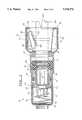
- FIG. 1is a partial sectional view of a quick connector coupling which embodies the present invention, shown in a fully assembled position;
- FIG. 2is front elevation view of a pull back retainer which is a part of the quick connector coupling of FIG. 1;
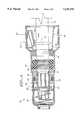
- FIGS. 3-5are a series of partial sectional views illustrating assembly steps for the quick connector coupling depicted in FIG. 1.
- a quick connector coupling formed in a fluid line systemis designated as 10 in FIG. 1.
- Quick connector coupling 10is comprised of a female connector body 20 and a male member 12 formed at an end of a tube 14 which forms a part of a fluid line system.
- connector body 20is, in turn, connected to flexible tubing (not shown) which is also a component of the fluid line system.
- Female connector body 20 and male member 12are connectable to form a permanent, but severable, joint.
- Female connector body 20is hollow and defines an axial bore 21 extending inwardly from an entrance 24.
- Connector body 20is preferably made of a metallic material, such as stainless steel.
- Entrance 24is defined by a radial annular rim 26, which in turn defines an interior abutment surface 28 and an exterior abutment surface 30.
- Enlarged retainer housing portion 22is formed in connector body 20 inwardly of rim 26.
- Seal housing portion 32is formed in connector body 20 inwardly of retainer housing portion 22. Seal housing portion 32 is of reduced diameter relative to retainer housing portion 22 and extends between a first conical shoulder 34 adjacent retainer housing portion 22 and a second conical shoulder 36 remote from retainer housing portion 22.
- Check valve housing portion 38is formed in connector body 20 inwardly of seal housing portion 32.
- Valve housing portion 38is of reduced diameter relative to seal housing portion 32 and extends between second conical shoulder 36 and an annular spring seating surface 40.
- Tubing connection portion 42is formed at an end of connector body 20 remote from entrance 24. Connection portion 42 is only partially illustrated in FIG. 1. Typically, barbs will be formed in its exterior to facilitate connection to flexible tubing and an open end will provide communication with the flexible tubing. Connection portion 42 could be configured in alternative ways for connection to other system arrangements. For example, threads could be formed in its outer periphery to facilitate connection within a threaded bore of a housing containing a system component.
- Male member 12is received within connector body 20 and includes an enlarged upset 16 formed a given distance from an open end 18. Open end 18 is in fluid communication with bore 21 of connector body 20. A cylindrical surface 17 extends between upset 16 and end 18. Male member 12 is typically formed at the end of a rigid, metal tube 14.
- seal housing portion 32Disposed within seal housing portion 32 are an outer annular "O” ring seal 44 and an inner annular “O” ring seal 46.
- "O” ring seals 44 and 46surround male member 12, forming a fluid-tight seal between cylindrical surface 17 of male member 12 and seal housing portion 32 of connector body 20.
- "O” ring seals 44 and 46are secured within bore 21 between outer spacer 48 and check valve guidance sleeve 50.
- Outer "O” ring seal 44is preferably made of toughened fluorosilicone and inner “O” ring seal 46 is preferably made of a fluorosilicone-fluorocarbon blend.
- Spacer 48 and sleeve 50also surround male member 12, having inner diameters just slightly larger than the outer diameter of cylindrical surface 17 of male member 12.
- Spacer 48 and sleeve 50preferably made of 23% glass-filled nylon-12, fit tightly and snugly within bore 21.
- Outer spacer 48includes a conical seat 52 which seats against conical shoulder 34 of connector body 20 to position spacer 48 within bore 21.
- Spacer 48also includes a chamfered guide portion 54 to assist and guide the insertion of male member 12.
- Check valve sleeve 50extends into check valve housing portion 38 of connector body 20 and includes a conical seat 56 which seats against second conical shoulder 36 to position sleeve 50 within bore 21.
- a third annular “O" ring 58is disposed in a groove 60 formed in the exterior of sleeve 50.
- "O" ring 58provides a fluid seal between sleeve 50 and check valve housing portion 38. It is preferably made of a fluoroelastomer, such as fluoroelastomers manufactured under the trademark "Viton”.
- a ring-shaped valve seat 62is formed on the innermost end of sleeve 50.
- a spring 66 and a plunger 68are also disposed in check valve portion 38 of connector body 20.
- Spring 66is preferably formed of stainless steel and plunger 68 is preferably formed of 23% glass-filled nylon-12.
- Plunger 68comprises a solid central portion 70, a hollow outer cylindrical portion 72 extending outwardly from central portion 70 and into sleeve 50, and a hollow inner cylindrical portion 74 extending inwardly from central portion 70.
- a seal in the form of an "O" ring 76surrounds, and is retained on, central portion 70 between a flange 77 and outer cylindrical portion 72.
- O ring 76has a square cross-section and is preferably made of a high fluorine fluoroelastomer, such as fluoroelastomers manufactured under the trademark "Viton”.
- the outer diameters of seal 76 and flange 77are less than the inner diameter of check valve housing portion 38, allowing fluid to flow around central portion 70 of plunger 68.
- Spring 66is conically-shaped, extending between a larger diameter end which seats against spring seating surface 40 of connector body 20, and a smaller diameter end which surrounds inner cylindrical portion 74 of plunger 68.
- the smaller diameter end of spring 66is retained on inner cylindrical portion 74 between flange 77 of central portion 70 and a barb 78 formed on the exterior of inner cylindrical portion 74.
- Axially-extending windows, or cut-out portions, 80extend through cylindrical portions 72 and 74 of plunger 68.
- the check valveWhen coupling 10 is fully assembled, as in FIG. 1, the check valve is open and permits fluid flow through the coupling. End 18 of male member 12 contacts the open end of outer cylindrical portion 72 of plunger 68, pushing plunger 68 inwardly and compressing spring 66. Windows 80 of cylinder 72 extend beyond sleeve 50, permitting fluid communication between male member 12 and tubing connection portion 42 of connector body 20.
- a pull back retainer 90is disposed within retainer housing section 22 of connector body 20.
- Retainer 90may be made of metal or, depending on its application, plastic.
- Retainer 90includes a hollow, annular ring 92 which surrounds male member 12. Ring 92 has an interior diameter which is approximately the same as the exterior diameter of cylindrical surface 17 of male member 12. Four legs are spaced equidistantly about the circumference of ring 92: a pair of 180 degree opposed retention legs 94 and a pair of 180 degree opposed latching verification legs 96. In FIGS. 1 and 3-5, a latching verification leg is shown 90 degrees out of alignment so that both legs may be illustrated.
- Each retention leg 94includes a support member 95, a retaining member 101 and two wings 104.
- Support members 95extend away from ring 92 to first bends 98.
- Legs 94reverse direction at bends 98.
- Retaining members 101continuous with support members 95 extend from bends 98 back toward ring 92 to second leg bends 100. Bends 100 are spaced from ring 92 and contact upset 16 to secure male member 12 in connector body 20.
- Retaining members 101are positioned "underneath" support members 95.
- Ramped bumps 102may be formed on retaining members 101 to provide enhanced stiffness to members 101 and enhanced resistance to insertion of male member 12.
- Wings 104extend circumferentially from the lateral edges of retaining members 101. They extend between an outer wing bend 103, remote from ring 92, and an inner wing bend 105, adjacent second leg bends 100.
- Wings 104extend to a position more remote from retainer ring 92 than do retaining members 101. Stated another way, wing bends 103 are spaced further from ring 92 than are leg bends 98. Thus, in operation, outer wing bends 103 contatct interior abutment surface 28 defined by annular rim 26 of connector body 20 to secure retainer 90 within bore 21. Leg bends 98 are held out of contact with body 20 during normal operation. Inner wing bends 105 contact upset 16 to assist second leg bends 100 in retaining male member 12 within connector body 20.
- Latching verification legs 96extend axially and radially outwardly of retainer ring 92 to latches 106. Apertures 108 may be formed in legs 96 to facilitate use of a tool to install retainer 90.
- latches 106When fully assembled as shown in FIG. 1, latches 106 are positioned outwardly of entrance 24 and engage exterior abutment surface 30 defined by rim 26 of connector body 20. The method by which latches 106 arrive at this position is a very important part of the present invention, and is described in detail below.
- Verification legs 96serve two functions: (1) they provide a visual indication that a proper coupling has been achieved; and (2) they prevent inward axial displacement of retainer 90.
- check valve, seal and retainer elementsPrior to insertion of male member 12 into connector body 20, the check valve, seal and retainer elements are installed in connector body bore 21.
- Spring 66is inserted into bore 21 and seated against seating surface 40.
- Plunger 68, with seal 76 fitted on,is then inserted until spring 66 snaps into place around inner cylindrical portion 74 between barb 78 and flange 77 of central portion 70.
- check valve sleeve 50is fit into bore 21 against second conical shoulder 36.
- "O" rings 44 and 46are inserted to rest against sleeve 50.
- Outer spacer 48is then fit against first conical shoulder 34 to secure the "O" rings in place.
- retainer 90is inserted into retainer housing portions 22. Legs 94 and 96 are flexed inwardly to clear rim 26 and gain entry into bore 21. An installation tool having prongs may be used in conjunction with apertures 108 formed on latching verification legs 96 to assist in this endeavor.
- Retainer 90should be initially inserted into bore 21 as far as possible until ring 92 abuts outer spacer 48. In this initial position (FIG. 3), outer wing bends 103 will be spaced inwardly from interior abutment surface 28, and latches 106 of latching verification legs 96 will be spaced inwardly of exterior abutment surface 30 and in radial alignment with rim 26.
- FIGS. 3-5illustrate the steps in installation leading to the fully assembled coupling of FIG. 1.
- insertion of male member 12has begun but open end 18 has not yet reached outer cylindrical portion 72 of plunger 68.
- end 18 of member 12contacts plunger 68 and pushes it forward, coupling 10 remains in a checked position as illustrated in FIG. 3.
- tube end 18has moved past "O" ring seals 44 and 46 to contact plunger 68.
- Plunger 68guided by sleeve 50, is moved axially inwardly.
- the guidance provide by sleeve 50is important as radial instability of plunger 68 could cause leakage and/or breakdown of the check valve.
- Spring 66is compressed in response. Seal 76 is unseated from valve seat 62 and windows 80 are exposed to bore 21. Thus, two-directional flow through the coupling may begin. It is important to note that no flow through the coupling occurs until tube end 18 has moved fully past "O" ring seals 44 and 46, fully sealing coupling 10.
- Latching verification legs 96have a greater internal diameter than the external diameter of upset 16. Thus, the presence of legs 96 does not hinder or affect insertion of male member 12. Likewise, inward insertion of male member 12 does not affect or change the position of legs 96. In the assembly steps illustrated in FIGS. 3 and 4 the position of legs 94 changes (they have flexed outwardly) while the position of legs 96 remains unchanged.
- male member 12has been inserted to a maximum inward axial position. Upset 16 abuts retainer ring 92 which, in turn, abuts outer spacer 48 to prevent further insertion of male member 12. End 18 of member 12 has moved plunger 68 to a fully open position. Seal 76 is separated from valve seat 62, and windows 80 of outer cylindrical portion 72 extend inwardly of sleeve 50. Retention leg members 101 have snapped back into place outward of upset 16. The position of latching verification legs 96, however, remains unchanged.
- the final assembly stepconsists of "pulling back” on male member 12 until upset 16 abuts second bends 100 of retention legs 94 and inner wing bends 105.
- the contact between second bends 100 and upset 16causes outward axial displacement of retainer 90 until outer wing bends 103 contact interior abutment surface 28 of connector body 20.
- male member 12cannot be pulled back any further, providing a physical verification of a proper coupling.
- latching verification legs 96are displaced outwardly along with retainer 90. This motion leads to the fully assembled position shown in FIG. 1.
- the check valveremains open even after the pull-back operation.
- latches 106move outwardly of entrance 24 to wrap around rim 26 and engage exerior abutment surface 30 of connector body 20.
- a proper couplingmay be visually verified by the presence of latches 106.
- Latches 106are of functional significance as well--the engagement of latches 106 with exterior abutment surface 30, in conjunction with the engagement of outer wing bends 103 with interior abutment surface 28, fixes the axial position of retainer 90.
Landscapes
- Engineering & Computer Science (AREA)
- General Engineering & Computer Science (AREA)
- Mechanical Engineering (AREA)
- Quick-Acting Or Multi-Walled Pipe Joints (AREA)
Abstract
Description
Claims (8)
Priority Applications (8)
| Application Number | Priority Date | Filing Date | Title |
|---|---|---|---|
| US08/308,087US5518276A (en) | 1994-09-16 | 1994-09-16 | Quick connector with pull back verification method |
| EP95306246AEP0702185A1 (en) | 1994-09-16 | 1995-09-07 | Quick connector, with pull back verification method |
| CA002157716ACA2157716C (en) | 1994-09-16 | 1995-09-07 | Quick connector with pull back verification method |
| JP7232178AJPH08303658A (en) | 1994-09-16 | 1995-09-11 | Quick connector fitting that allows visual confirmation of connection |
| MXPA95003906AMXPA95003906A (en) | 1994-09-16 | 1995-09-13 | Quick connector with pull back verification method. |
| AU30654/95AAU690310B2 (en) | 1994-09-16 | 1995-09-14 | Quick connector with pull back verification method |
| KR1019950030245AKR100349810B1 (en) | 1994-09-16 | 1995-09-15 | Quick connector with rear towing test |
| BR9504039ABR9504039A (en) | 1994-09-16 | 1995-09-15 | Quick connector coupling and method and formation of a quick connector coupling joint |
Applications Claiming Priority (1)
| Application Number | Priority Date | Filing Date | Title |
|---|---|---|---|
| US08/308,087US5518276A (en) | 1994-09-16 | 1994-09-16 | Quick connector with pull back verification method |
Publications (1)
| Publication Number | Publication Date |
|---|---|
| US5518276Atrue US5518276A (en) | 1996-05-21 |
Family
ID=23192492
Family Applications (1)
| Application Number | Title | Priority Date | Filing Date |
|---|---|---|---|
| US08/308,087Expired - LifetimeUS5518276A (en) | 1994-09-16 | 1994-09-16 | Quick connector with pull back verification method |
Country Status (8)
| Country | Link |
|---|---|
| US (1) | US5518276A (en) |
| EP (1) | EP0702185A1 (en) |
| JP (1) | JPH08303658A (en) |
| KR (1) | KR100349810B1 (en) |
| AU (1) | AU690310B2 (en) |
| BR (1) | BR9504039A (en) |
| CA (1) | CA2157716C (en) |
| MX (1) | MXPA95003906A (en) |
Cited By (26)
| Publication number | Priority date | Publication date | Assignee | Title |
|---|---|---|---|---|
| US5779278A (en)* | 1995-12-27 | 1998-07-14 | Itt Automotive, Inc. | Pop off insertion indicator for metal quick connectors |
| US5785358A (en)* | 1994-09-26 | 1998-07-28 | Bundy Corporation | Connection verifier for a quick connector coupling |
| US6257626B1 (en) | 1999-04-27 | 2001-07-10 | Flow-Rite Controls, Ltd. | Connector for fluid handling system |
| US6340180B1 (en) | 1999-01-19 | 2002-01-22 | David M. Wisniewski | Releasable coupling assembly for securing a vehicle fuel line |
| US20030184088A1 (en)* | 2002-03-29 | 2003-10-02 | Akira Takayanagi | Quick connector |
| US20040240940A1 (en)* | 2003-05-29 | 2004-12-02 | Ericksen Kent C. | Irrigation coupling apparatus and method |
| US20050197646A1 (en)* | 2002-02-11 | 2005-09-08 | Brian Connell | Dialysis connector with retention and feedback features |
| US20070020973A1 (en)* | 2005-07-20 | 2007-01-25 | Ims Connector Systems Gmbh | Connector plug and mating plug |
| US20070075542A1 (en)* | 2004-05-19 | 2007-04-05 | Glaze Alan R | Pipe fitting |
| US20090160178A1 (en)* | 2003-05-29 | 2009-06-25 | Ericksen Kent C | Centering system for coupling for irrigation system |
| US20090160179A1 (en)* | 2003-05-29 | 2009-06-25 | Ericksen Kent C | Coupling release mechanism for irrigation system |
| US20100088869A1 (en)* | 2007-02-01 | 2010-04-15 | Ibp Ipr Limited | Insertion and release tool for pipe fitting arrangement and method using such tool |
| US20100130919A1 (en)* | 2008-11-21 | 2010-05-27 | Baxter International Inc. | Systems and methods for removing air from the patient's peritoneal cavity |
| US20100130918A1 (en)* | 2008-11-21 | 2010-05-27 | Baxter International Inc. | Systems and methods for removing air from supply containers and associated fill tubing |
| US7862090B1 (en) | 2007-12-28 | 2011-01-04 | R.L. Hudson & Company | Plug-in fitting for direct connection to housing |
| US20120284980A1 (en)* | 2009-10-21 | 2012-11-15 | Turnau Iii William Franklin | Supply stop with connection verification |
| USD687702S1 (en) | 2011-05-09 | 2013-08-13 | Joy Mm Delaware, Inc. | Hose clip |
| USD711516S1 (en)* | 2011-12-09 | 2014-08-19 | John Guest International Limited | Fluid connector |
| USD712014S1 (en)* | 2011-12-09 | 2014-08-26 | John Guest International Limited | Fluid connector |
| USD732359S1 (en) | 2012-08-21 | 2015-06-23 | Orbit Irrigation Products, Inc. | Conduit removal tool |
| US9429262B2 (en) | 2003-05-29 | 2016-08-30 | Orbit Irrigation Products, Inc. | Conduit coupling apparatus and method |
| US9604404B2 (en) | 2003-05-29 | 2017-03-28 | Orbit Irrigation Products, Inc. | Conduit coupling apparatus and method |
| US9816652B2 (en)* | 2013-04-17 | 2017-11-14 | A. Raymond Et Cie | Lock for a tubular connection |
| CN107910818A (en)* | 2017-12-29 | 2018-04-13 | 郑州拽亘电子科技有限公司 | A kind of cable stripping tool |
| US11384872B1 (en) | 2011-05-24 | 2022-07-12 | Husqvarna Ab | Conduit coupling apparatus and method |
| US20230383879A1 (en)* | 2022-05-24 | 2023-11-30 | RB Distribution, Inc. | Double sided connector |
Families Citing this family (7)
| Publication number | Priority date | Publication date | Assignee | Title |
|---|---|---|---|---|
| US5499848A (en)* | 1994-09-26 | 1996-03-19 | Bundy Corporation | Connection verifier for a quick connector coupling |
| US7014224B1 (en) | 1999-04-06 | 2006-03-21 | Optimum Innovations Australia | Fluid line connector |
| KR100479637B1 (en)* | 2002-02-01 | 2005-03-31 | 한국화학연구원 | Oral dosage form comprising Lansoprazole and preparation method for the same |
| JP4826727B2 (en)* | 2005-09-28 | 2011-11-30 | 日立金属株式会社 | Pipe fitting |
| JP5444678B2 (en)* | 2008-10-10 | 2014-03-19 | セイコーエプソン株式会社 | Flow path connection joint |
| NL1036410C2 (en)* | 2009-01-12 | 2010-07-13 | Wavin Bv | Push-fit pipe connector with improved gripping assembly. |
| KR101984278B1 (en)* | 2017-06-19 | 2019-05-30 | 조재훈 | Pipe connector |
Citations (27)
| Publication number | Priority date | Publication date | Assignee | Title |
|---|---|---|---|---|
| US2661768A (en)* | 1949-10-29 | 1953-12-08 | Standard Oil Dev Co | Indicating orifice plate for threaded orifice union |
| US4035005A (en)* | 1976-05-24 | 1977-07-12 | General Motors Corporation | Quick connect coupling with weather seal |
| US4712810A (en)* | 1985-11-25 | 1987-12-15 | Pozzi Gian C | Quick action self-locking pipe fittings |
| US4753458A (en)* | 1986-08-28 | 1988-06-28 | Harvard Industries, Inc. | Quick connector assembly |
| US4781400A (en)* | 1987-07-01 | 1988-11-01 | General Motors Corporation | Quick connect tube coupling |
| US4875715A (en)* | 1988-04-22 | 1989-10-24 | Itt Corporation | Quick connect connector |
| US4895396A (en)* | 1988-03-08 | 1990-01-23 | Usui Kokusai Sangyo Kaisha Ltd. | Connector for connecting small diameter pipe |
| US4913467A (en)* | 1988-03-03 | 1990-04-03 | Usui Kokusai Sangyo Kaisha Ltd. | Connector for connecting small diameter pipe |
| US4915420A (en)* | 1988-03-05 | 1990-04-10 | Usui Kokusai Sangyo Kaisha Ltd. | Connector for connecting pipe |
| US4925217A (en)* | 1988-10-24 | 1990-05-15 | Huron Products Corporation | Quick connector with visual checking method |
| US4936544A (en)* | 1980-10-29 | 1990-06-26 | Proprietary Technology, Inc. | Swivelable quick connector assembly |
| US4946205A (en)* | 1988-03-01 | 1990-08-07 | Usui Kokusai Sangyo Kaisha Ltd. | Connector for connecting small diameter pipe |
| US4948176A (en)* | 1987-09-14 | 1990-08-14 | Proprietary Technology, Inc. | Swivelable quick connector assembly |
| US4979765A (en)* | 1980-10-29 | 1990-12-25 | Proprietary Technology, Inc. | Swivelable quick connector assembly |
| US4981586A (en)* | 1980-10-29 | 1991-01-01 | Proprietary Technology, Inc. | Swivelable quick connector assembly |
| US5069424A (en)* | 1990-10-17 | 1991-12-03 | Itt Corporation | Quick connector |
| US5112084A (en)* | 1989-02-07 | 1992-05-12 | Usui Kokusai Sangyo Kaisha, Ltd. | Connector for small-diameter piping |
| US5131691A (en)* | 1989-08-23 | 1992-07-21 | Usui Kokusai Sangyo Kaisha Ltd. | Snap-fit connector for connecting slender piping members at end portions |
| US5152555A (en)* | 1991-03-26 | 1992-10-06 | Itt Corporation | Quick connect insertion indicator clip |
| US5161833A (en)* | 1991-08-29 | 1992-11-10 | Huron Products Industries, Inc. | Positive transition quick connect coupling |
| US5163720A (en)* | 1989-12-04 | 1992-11-17 | Kabushiki Kaisha Daikin Seisakusho | Pipe joint |
| US5178424A (en)* | 1991-07-01 | 1993-01-12 | Itt Corporation | Pop-off quick connect indicator |
| US5226679A (en)* | 1991-05-16 | 1993-07-13 | Itt Corporation | Quick connect insertion indicator |
| US5228728A (en)* | 1991-12-17 | 1993-07-20 | Huron Products Industries, Inc. | Tube retainer release sleeve |
| US5297818A (en)* | 1991-12-18 | 1994-03-29 | Itt Corporation | Retainer for pop-top indicator |
| US5303963A (en)* | 1992-03-27 | 1994-04-19 | Bundy Corporation | Tube coupling with secondary retainer clip |
| US5342099A (en)* | 1992-02-25 | 1994-08-30 | Rasmussen Gmbh | Fluid coupling with condition indicator |
Family Cites Families (3)
| Publication number | Priority date | Publication date | Assignee | Title |
|---|---|---|---|---|
| US4601497A (en)* | 1980-10-29 | 1986-07-22 | Proprietary Technology | Swivelable quick connector assembly |
| US4793637A (en) | 1987-09-14 | 1988-12-27 | Aeroquip Corporation | Tube connector with indicator and release |
| JP2530220Y2 (en)* | 1990-01-10 | 1997-03-26 | 臼井国際産業株式会社 | Connector for small-diameter piping connection |
- 1994
- 1994-09-16USUS08/308,087patent/US5518276A/ennot_activeExpired - Lifetime
- 1995
- 1995-09-07EPEP95306246Apatent/EP0702185A1/ennot_activeWithdrawn
- 1995-09-07CACA002157716Apatent/CA2157716C/ennot_activeExpired - Fee Related
- 1995-09-11JPJP7232178Apatent/JPH08303658A/enactivePending
- 1995-09-13MXMXPA95003906Apatent/MXPA95003906A/enunknown
- 1995-09-14AUAU30654/95Apatent/AU690310B2/ennot_activeCeased
- 1995-09-15BRBR9504039Apatent/BR9504039A/ennot_activeIP Right Cessation
- 1995-09-15KRKR1019950030245Apatent/KR100349810B1/ennot_activeExpired - Fee Related
Patent Citations (27)
| Publication number | Priority date | Publication date | Assignee | Title |
|---|---|---|---|---|
| US2661768A (en)* | 1949-10-29 | 1953-12-08 | Standard Oil Dev Co | Indicating orifice plate for threaded orifice union |
| US4035005A (en)* | 1976-05-24 | 1977-07-12 | General Motors Corporation | Quick connect coupling with weather seal |
| US4981586A (en)* | 1980-10-29 | 1991-01-01 | Proprietary Technology, Inc. | Swivelable quick connector assembly |
| US4979765A (en)* | 1980-10-29 | 1990-12-25 | Proprietary Technology, Inc. | Swivelable quick connector assembly |
| US4936544A (en)* | 1980-10-29 | 1990-06-26 | Proprietary Technology, Inc. | Swivelable quick connector assembly |
| US4712810A (en)* | 1985-11-25 | 1987-12-15 | Pozzi Gian C | Quick action self-locking pipe fittings |
| US4753458A (en)* | 1986-08-28 | 1988-06-28 | Harvard Industries, Inc. | Quick connector assembly |
| US4781400A (en)* | 1987-07-01 | 1988-11-01 | General Motors Corporation | Quick connect tube coupling |
| US4948176A (en)* | 1987-09-14 | 1990-08-14 | Proprietary Technology, Inc. | Swivelable quick connector assembly |
| US4946205A (en)* | 1988-03-01 | 1990-08-07 | Usui Kokusai Sangyo Kaisha Ltd. | Connector for connecting small diameter pipe |
| US4913467A (en)* | 1988-03-03 | 1990-04-03 | Usui Kokusai Sangyo Kaisha Ltd. | Connector for connecting small diameter pipe |
| US4915420A (en)* | 1988-03-05 | 1990-04-10 | Usui Kokusai Sangyo Kaisha Ltd. | Connector for connecting pipe |
| US4895396A (en)* | 1988-03-08 | 1990-01-23 | Usui Kokusai Sangyo Kaisha Ltd. | Connector for connecting small diameter pipe |
| US4875715A (en)* | 1988-04-22 | 1989-10-24 | Itt Corporation | Quick connect connector |
| US4925217A (en)* | 1988-10-24 | 1990-05-15 | Huron Products Corporation | Quick connector with visual checking method |
| US5112084A (en)* | 1989-02-07 | 1992-05-12 | Usui Kokusai Sangyo Kaisha, Ltd. | Connector for small-diameter piping |
| US5131691A (en)* | 1989-08-23 | 1992-07-21 | Usui Kokusai Sangyo Kaisha Ltd. | Snap-fit connector for connecting slender piping members at end portions |
| US5163720A (en)* | 1989-12-04 | 1992-11-17 | Kabushiki Kaisha Daikin Seisakusho | Pipe joint |
| US5069424A (en)* | 1990-10-17 | 1991-12-03 | Itt Corporation | Quick connector |
| US5152555A (en)* | 1991-03-26 | 1992-10-06 | Itt Corporation | Quick connect insertion indicator clip |
| US5226679A (en)* | 1991-05-16 | 1993-07-13 | Itt Corporation | Quick connect insertion indicator |
| US5178424A (en)* | 1991-07-01 | 1993-01-12 | Itt Corporation | Pop-off quick connect indicator |
| US5161833A (en)* | 1991-08-29 | 1992-11-10 | Huron Products Industries, Inc. | Positive transition quick connect coupling |
| US5228728A (en)* | 1991-12-17 | 1993-07-20 | Huron Products Industries, Inc. | Tube retainer release sleeve |
| US5297818A (en)* | 1991-12-18 | 1994-03-29 | Itt Corporation | Retainer for pop-top indicator |
| US5342099A (en)* | 1992-02-25 | 1994-08-30 | Rasmussen Gmbh | Fluid coupling with condition indicator |
| US5303963A (en)* | 1992-03-27 | 1994-04-19 | Bundy Corporation | Tube coupling with secondary retainer clip |
Cited By (43)
| Publication number | Priority date | Publication date | Assignee | Title |
|---|---|---|---|---|
| US5785358A (en)* | 1994-09-26 | 1998-07-28 | Bundy Corporation | Connection verifier for a quick connector coupling |
| US5779278A (en)* | 1995-12-27 | 1998-07-14 | Itt Automotive, Inc. | Pop off insertion indicator for metal quick connectors |
| US6340180B1 (en) | 1999-01-19 | 2002-01-22 | David M. Wisniewski | Releasable coupling assembly for securing a vehicle fuel line |
| US6257626B1 (en) | 1999-04-27 | 2001-07-10 | Flow-Rite Controls, Ltd. | Connector for fluid handling system |
| US20050197646A1 (en)* | 2002-02-11 | 2005-09-08 | Brian Connell | Dialysis connector with retention and feedback features |
| US7708714B2 (en) | 2002-02-11 | 2010-05-04 | Baxter International Inc. | Dialysis connector with retention and feedback features |
| US7108297B2 (en)* | 2002-03-29 | 2006-09-19 | Tokai Rubber Industries, Inc. | Quick connector |
| US20030184088A1 (en)* | 2002-03-29 | 2003-10-02 | Akira Takayanagi | Quick connector |
| US7021672B2 (en) | 2003-05-29 | 2006-04-04 | Orbit Irrigation Products, Inc. | Irrigation coupling apparatus and method |
| US20040240940A1 (en)* | 2003-05-29 | 2004-12-02 | Ericksen Kent C. | Irrigation coupling apparatus and method |
| US20090160178A1 (en)* | 2003-05-29 | 2009-06-25 | Ericksen Kent C | Centering system for coupling for irrigation system |
| US20090160179A1 (en)* | 2003-05-29 | 2009-06-25 | Ericksen Kent C | Coupling release mechanism for irrigation system |
| US10724661B2 (en) | 2003-05-29 | 2020-07-28 | Orbit Irrigation Products, Llc | Conduit coupling apparatus and method |
| US9604404B2 (en) | 2003-05-29 | 2017-03-28 | Orbit Irrigation Products, Inc. | Conduit coupling apparatus and method |
| US9429262B2 (en) | 2003-05-29 | 2016-08-30 | Orbit Irrigation Products, Inc. | Conduit coupling apparatus and method |
| US20070075542A1 (en)* | 2004-05-19 | 2007-04-05 | Glaze Alan R | Pipe fitting |
| US20070020973A1 (en)* | 2005-07-20 | 2007-01-25 | Ims Connector Systems Gmbh | Connector plug and mating plug |
| US7238047B2 (en)* | 2005-07-20 | 2007-07-03 | Ims Connector Systems Gmbh | Connector plug and mating plug |
| US8424179B2 (en) | 2007-02-01 | 2013-04-23 | Conex Universal Limited | Insertion and release tool for pipe fitting arrangement and method using such tool |
| US20100088869A1 (en)* | 2007-02-01 | 2010-04-15 | Ibp Ipr Limited | Insertion and release tool for pipe fitting arrangement and method using such tool |
| US7862090B1 (en) | 2007-12-28 | 2011-01-04 | R.L. Hudson & Company | Plug-in fitting for direct connection to housing |
| US20100130918A1 (en)* | 2008-11-21 | 2010-05-27 | Baxter International Inc. | Systems and methods for removing air from supply containers and associated fill tubing |
| US20100130919A1 (en)* | 2008-11-21 | 2010-05-27 | Baxter International Inc. | Systems and methods for removing air from the patient's peritoneal cavity |
| US9555180B2 (en) | 2008-11-21 | 2017-01-31 | Baxter International Inc. | Systems and methods for removing air from the patient's peritoneal cavity |
| US20120284980A1 (en)* | 2009-10-21 | 2012-11-15 | Turnau Iii William Franklin | Supply stop with connection verification |
| US9506592B2 (en)* | 2009-10-21 | 2016-11-29 | Brass-Craft Manufacturing Company | Supply stop with connection verification |
| USD687702S1 (en) | 2011-05-09 | 2013-08-13 | Joy Mm Delaware, Inc. | Hose clip |
| US11384872B1 (en) | 2011-05-24 | 2022-07-12 | Husqvarna Ab | Conduit coupling apparatus and method |
| USD731627S1 (en) | 2011-12-09 | 2015-06-09 | John Guest International Limited | Fluid connector |
| USD731628S1 (en) | 2011-12-09 | 2015-06-09 | John Guest International Limited | Fluid connector |
| USD741459S1 (en) | 2011-12-09 | 2015-10-20 | John Guest International Limited | Fluid connector |
| USD741458S1 (en) | 2011-12-09 | 2015-10-20 | John Guest International Limited | Fluid connector |
| USD733846S1 (en) | 2011-12-09 | 2015-07-07 | John Guest International Limited | Fluid connector |
| USD711516S1 (en)* | 2011-12-09 | 2014-08-19 | John Guest International Limited | Fluid connector |
| USD712014S1 (en)* | 2011-12-09 | 2014-08-26 | John Guest International Limited | Fluid connector |
| USD741457S1 (en) | 2011-12-09 | 2015-10-20 | John Guest Internaitonal Limited | Fluid connector |
| USD811182S1 (en) | 2012-08-21 | 2018-02-27 | Orbit Irrigation Products, Inc. | Conduit removal tool |
| USD732359S1 (en) | 2012-08-21 | 2015-06-23 | Orbit Irrigation Products, Inc. | Conduit removal tool |
| USD776998S1 (en) | 2012-08-21 | 2017-01-24 | Orbit Irrigation Products, Inc. | Conduit removal tool |
| US9816652B2 (en)* | 2013-04-17 | 2017-11-14 | A. Raymond Et Cie | Lock for a tubular connection |
| CN107910818A (en)* | 2017-12-29 | 2018-04-13 | 郑州拽亘电子科技有限公司 | A kind of cable stripping tool |
| CN107910818B (en)* | 2017-12-29 | 2023-10-27 | 河南卓迈电力科技有限公司 | Wire stripping tool for cable |
| US20230383879A1 (en)* | 2022-05-24 | 2023-11-30 | RB Distribution, Inc. | Double sided connector |
Also Published As
| Publication number | Publication date |
|---|---|
| CA2157716C (en) | 2001-07-31 |
| KR960011237A (en) | 1996-04-20 |
| EP0702185A1 (en) | 1996-03-20 |
| KR100349810B1 (en) | 2002-11-07 |
| MXPA95003906A (en) | 2006-02-28 |
| BR9504039A (en) | 1996-09-24 |
| CA2157716A1 (en) | 1996-03-17 |
| AU690310B2 (en) | 1998-04-23 |
| JPH08303658A (en) | 1996-11-22 |
| AU3065495A (en) | 1996-03-28 |
Similar Documents
| Publication | Publication Date | Title |
|---|---|---|
| US5518276A (en) | Quick connector with pull back verification method | |
| US5485982A (en) | Quick connector with tube activated check valve | |
| CA2140423C (en) | Quick connect tubing connector and method of assembly | |
| US5441313A (en) | Insertion indicator for quick connector | |
| US6086118A (en) | Quick connect tubing connector | |
| US5695224A (en) | Pipe joint assembly | |
| EP1098127B1 (en) | Insertion verifier dust cap | |
| EP0901592B1 (en) | Connection verifier for a quick connector coupling | |
| JP3648644B2 (en) | Quick connector fitting with visual connection confirmation | |
| CA2310179C (en) | Coupling assemblies for providing fluid connection | |
| US5368275A (en) | Fluid line adapter | |
| EP1559945B1 (en) | False insertion protection top hat for fluid quick connectors | |
| US6412826B1 (en) | High pressure quick connector | |
| MXPA95003908A (en) | Fast connector with control valve or retensionactivated by t | |
| EP0800630A1 (en) | Connector assemblies which compensate for thermal expansion and contraction of tubular conduits | |
| MXPA00007494A (en) | Coupling assemblies for providing fluid connection |
Legal Events
| Date | Code | Title | Description |
|---|---|---|---|
| AS | Assignment | Owner name:BUNDY CORPORATION, MICHIGAN Free format text:ASSIGNMENT OF ASSIGNORS INTEREST;ASSIGNOR:GUNDERSON, STEPHEN H.;REEL/FRAME:007155/0328 Effective date:19940913 | |
| STCF | Information on status: patent grant | Free format text:PATENTED CASE | |
| FPAY | Fee payment | Year of fee payment:4 | |
| AS | Assignment | Owner name:TI GROUP AUTOMOTIVE SYSTEMS CORPORATION, MICHIGAN Free format text:CHANGE OF NAME;ASSIGNOR:BUNDY CORPORATION;REEL/FRAME:010859/0541 Effective date:19991012 | |
| AS | Assignment | Owner name:TI GROUP AUTOMOTIVE SYSTEMS, LLC, MICHIGAN Free format text:MERGER;ASSIGNOR:TI GROUP AUTOMOTIVE SYSTEMS CORPORATION;REEL/FRAME:012407/0436 Effective date:20010625 | |
| FPAY | Fee payment | Year of fee payment:8 | |
| FEPP | Fee payment procedure | Free format text:PAYOR NUMBER ASSIGNED (ORIGINAL EVENT CODE: ASPN); ENTITY STATUS OF PATENT OWNER: LARGE ENTITY | |
| AS | Assignment | Owner name:JPMORGAN CHASE BANK, N.A., NEW YORK Free format text:SECURITY AGREEMENT;ASSIGNORS:HANIL USA, L.L.C.;TI AUTOMOTIVE, L.L.C.;TI GROUP AUTOMOTIVE SYSTEMS, L.L.C.;REEL/FRAME:019733/0933 Effective date:20070629 Owner name:JPMORGAN CHASE BANK, N.A.,NEW YORK Free format text:SECURITY AGREEMENT;ASSIGNORS:HANIL USA, L.L.C.;TI AUTOMOTIVE, L.L.C.;TI GROUP AUTOMOTIVE SYSTEMS, L.L.C.;REEL/FRAME:019733/0933 Effective date:20070629 | |
| FPAY | Fee payment | Year of fee payment:12 | |
| REMI | Maintenance fee reminder mailed | ||
| AS | Assignment | Owner name:WILMINGTON TRUST (LONDON) LIMITED,UNITED KINGDOM Free format text:ASSIGNMENT OF SECURITY INTEREST;ASSIGNOR:JP MORGAN CHASE BANK, N.A.;REEL/FRAME:024055/0633 Effective date:20100208 Owner name:WILMINGTON TRUST (LONDON) LIMITED, UNITED KINGDOM Free format text:ASSIGNMENT OF SECURITY INTEREST;ASSIGNOR:JP MORGAN CHASE BANK, N.A.;REEL/FRAME:024055/0633 Effective date:20100208 | |
| AS | Assignment | Owner name:TI GROUP AUTOMOTIVE SYSTEMS, L.L.C., MICHIGAN Free format text:RELEASE AND TERMINATION OF PATENT SECURITY INTEREST;ASSIGNOR:WILMINGTON TRUST (LONDON) LIMITED (AS SUCCESSOR IN INTEREST TO JP MORGAN CHASE BANK, N.A.);REEL/FRAME:024891/0671 Effective date:20100825 Owner name:CITIBANK N.A., DELAWARE Free format text:ABL PATENT SECURITY AGREEMENT;ASSIGNOR:TI GROUP AUTOMOTIVE SYSTEMS, L.L.C.;REEL/FRAME:024895/0956 Effective date:20100825 Owner name:CITIBANK N.A., DELAWARE Free format text:TERM PATENT SECURITY AGREEMENT;ASSIGNOR:TI GROUP AUTOMOTIVE SYSTEMS, L.L.C.;REEL/FRAME:024896/0057 Effective date:20100825 Owner name:HANIL USA, L.L.C., MICHIGAN Free format text:RELEASE AND TERMINATION OF PATENT SECURITY INTEREST;ASSIGNOR:WILMINGTON TRUST (LONDON) LIMITED (AS SUCCESSOR IN INTEREST TO JP MORGAN CHASE BANK, N.A.);REEL/FRAME:024891/0671 Effective date:20100825 Owner name:TI AUTOMOTIVE, L.L.C., MICHIGAN Free format text:RELEASE AND TERMINATION OF PATENT SECURITY INTEREST;ASSIGNOR:WILMINGTON TRUST (LONDON) LIMITED (AS SUCCESSOR IN INTEREST TO JP MORGAN CHASE BANK, N.A.);REEL/FRAME:024891/0671 Effective date:20100825 | |
| AS | Assignment | Owner name:JPMORGAN CHASE BANK, N.A., NEW YORK Free format text:SECURITY AGREEMENT;ASSIGNORS:TI GROUP AUTOMOTIVE SYSTEMS, L.L.C.;TI AUTOMOTIVE LIMITED;TI AUTOMOTIVE CANADA, INC.;AND OTHERS;REEL/FRAME:027864/0968 Effective date:20120314 Owner name:TI GROUP AUTOMOTIVE SYSTEMS, L.L.C., MICHIGAN Free format text:RELEASE BY SECURED PARTY;ASSIGNOR:CITIBANK, N.A.;REEL/FRAME:027865/0016 Effective date:20120314 | |
| AS | Assignment | Owner name:TI GROUP AUTOMOTIVE SYSTEMS, L.L.C., MICHIGAN Free format text:TERMINATION AND RELEASE;ASSIGNOR:JPMORGAN CHASE BANK, N.A., AS ADMINISTRATIVE AGENT;REEL/FRAME:036013/0775 Effective date:20150630 Owner name:TI AUTOMOTIVE CANADA, INC., CANADA Free format text:TERMINATION AND RELEASE;ASSIGNOR:JPMORGAN CHASE BANK, N.A., AS ADMINISTRATIVE AGENT;REEL/FRAME:036013/0775 Effective date:20150630 Owner name:JPMORGAN CHASE BANK, N.A., AS THE COLLATERAL AGENT Free format text:SECURITY AGREEMENT;ASSIGNORS:TI GROUP AUTOMOTIVE SYSTEMS, L.L.C.;HANIL USA, L.L.C.;TI AUTOMOTIVE, L.L.C.;REEL/FRAME:036013/0666 Effective date:20150630 Owner name:TI GROUP AUTOMOTIVE SYSTEMS S DE R.L. DE C.V., MEX Free format text:TERMINATION AND RELEASE;ASSIGNOR:JPMORGAN CHASE BANK, N.A., AS ADMINISTRATIVE AGENT;REEL/FRAME:036013/0775 Effective date:20150630 Owner name:TI AUTOMOTIVE LIMITED, UNITED KINGDOM Free format text:TERMINATION AND RELEASE;ASSIGNOR:JPMORGAN CHASE BANK, N.A., AS ADMINISTRATIVE AGENT;REEL/FRAME:036013/0775 Effective date:20150630 Owner name:HANIL USA L.L.C., ALABAMA Free format text:TERMINATION AND RELEASE;ASSIGNOR:JPMORGAN CHASE BANK, N.A., AS ADMINISTRATIVE AGENT;REEL/FRAME:036013/0775 Effective date:20150630 Owner name:TI AUTOMOTIVE, L.L.C., MICHIGAN Free format text:TERMINATION AND RELEASE;ASSIGNOR:JPMORGAN CHASE BANK, N.A., AS ADMINISTRATIVE AGENT;REEL/FRAME:036013/0775 Effective date:20150630 | |
| AS | Assignment | Owner name:MILLENIUM INDUSTRIES CORPORATION, MICHIGAN Free format text:RELEASE OF SECURITY INTEREST (REEL 036013, FRAME 0666);ASSIGNOR:JPMORGAN CHASE BANK, N.A., AS COLLATERAL AGENT;REEL/FRAME:070917/0957 Effective date:20250422 Owner name:TI AUTOMOTIVE, L.L.C., MICHIGAN Free format text:RELEASE OF SECURITY INTEREST (REEL 036013, FRAME 0666);ASSIGNOR:JPMORGAN CHASE BANK, N.A., AS COLLATERAL AGENT;REEL/FRAME:070917/0957 Effective date:20250422 Owner name:HANIL USA, L.L.C., ALABAMA Free format text:RELEASE OF SECURITY INTEREST (REEL 036013, FRAME 0666);ASSIGNOR:JPMORGAN CHASE BANK, N.A., AS COLLATERAL AGENT;REEL/FRAME:070917/0957 Effective date:20250422 Owner name:TI GROUP AUTOMOTIVE SYSTEMS, L.L.C., MICHIGAN Free format text:RELEASE OF SECURITY INTEREST (REEL 036013, FRAME 0666);ASSIGNOR:JPMORGAN CHASE BANK, N.A., AS COLLATERAL AGENT;REEL/FRAME:070917/0957 Effective date:20250422 |