US5518257A - Seal device for flow line applications - Google Patents
Seal device for flow line applicationsDownload PDFInfo
- Publication number
- US5518257A US5518257AUS08/110,562US11056293AUS5518257AUS 5518257 AUS5518257 AUS 5518257AUS 11056293 AUS11056293 AUS 11056293AUS 5518257 AUS5518257 AUS 5518257A
- Authority
- US
- United States
- Prior art keywords
- seal
- annular
- retainer
- seal device
- compressed
- Prior art date
- Legal status (The legal status is an assumption and is not a legal conclusion. Google has not performed a legal analysis and makes no representation as to the accuracy of the status listed.)
- Expired - Lifetime
Links
- 239000012530fluidSubstances0.000claimsabstractdescription57
- 125000006850spacer groupChemical group0.000claimsabstractdescription53
- 239000000463materialSubstances0.000claimsabstractdescription47
- 238000007789sealingMethods0.000claimsabstractdescription21
- 230000002093peripheral effectEffects0.000claimsabstractdescription11
- 238000001125extrusionMethods0.000claimsdescription30
- 229920001971elastomerPolymers0.000claimsdescription28
- 239000000806elastomerSubstances0.000claimsdescription28
- 230000007797corrosionEffects0.000claimsdescription19
- 238000005260corrosionMethods0.000claimsdescription19
- 239000012528membraneSubstances0.000claimsdescription17
- 229920001343polytetrafluoroethylenePolymers0.000claimsdescription10
- -1perfluorelastomersPolymers0.000claimsdescription9
- 229910001069Ti alloyInorganic materials0.000claimsdescription7
- 229910001256stainless steel alloyInorganic materials0.000claimsdescription7
- 229920000642polymerPolymers0.000claimsdescription4
- 239000004696Poly ether ether ketoneSubstances0.000claimsdescription3
- 229920002530polyetherether ketonePolymers0.000claimsdescription3
- 210000004779membrane envelopeAnatomy0.000claims2
- 229910052751metalInorganic materials0.000description10
- 239000002184metalSubstances0.000description10
- 230000002706hydrostatic effectEffects0.000description8
- 239000013536elastomeric materialSubstances0.000description7
- 230000006835compressionEffects0.000description5
- 238000007906compressionMethods0.000description5
- 230000008602contractionEffects0.000description5
- RTAQQCXQSZGOHL-UHFFFAOYSA-NTitaniumChemical compound[Ti]RTAQQCXQSZGOHL-UHFFFAOYSA-N0.000description4
- 229910001220stainless steelInorganic materials0.000description4
- 239000010935stainless steelSubstances0.000description4
- 239000010936titaniumSubstances0.000description4
- 229910052719titaniumInorganic materials0.000description4
- 238000013461designMethods0.000description3
- 238000004886process controlMethods0.000description3
- VEXZGXHMUGYJMC-UHFFFAOYSA-NHydrochloric acidChemical compoundClVEXZGXHMUGYJMC-UHFFFAOYSA-N0.000description2
- MHAJPDPJQMAIIY-UHFFFAOYSA-NHydrogen peroxideChemical compoundOOMHAJPDPJQMAIIY-UHFFFAOYSA-N0.000description2
- 238000005516engineering processMethods0.000description2
- 239000007789gasSubstances0.000description2
- 238000004519manufacturing processMethods0.000description2
- 238000012545processingMethods0.000description2
- 239000000126substanceSubstances0.000description2
- 239000004593EpoxySubstances0.000description1
- 230000002378acidificating effectEffects0.000description1
- 239000006227byproductSubstances0.000description1
- 239000003518causticsSubstances0.000description1
- 239000011248coating agentSubstances0.000description1
- 238000000576coating methodMethods0.000description1
- 238000002485combustion reactionMethods0.000description1
- 238000004891communicationMethods0.000description1
- 150000001875compoundsChemical class0.000description1
- 238000011982device technologyMethods0.000description1
- 230000003292diminished effectEffects0.000description1
- 230000000694effectsEffects0.000description1
- 230000007613environmental effectEffects0.000description1
- 238000009434installationMethods0.000description1
- 238000012423maintenanceMethods0.000description1
- 229910001092metal group alloyInorganic materials0.000description1
- 150000002739metalsChemical class0.000description1
- 238000012986modificationMethods0.000description1
- 230000004048modificationEffects0.000description1
- 230000009972noncorrosive effectEffects0.000description1
- 239000003921oilSubstances0.000description1
- 239000002861polymer materialSubstances0.000description1
- 238000003825pressingMethods0.000description1
- 230000000153supplemental effectEffects0.000description1
- XLYOFNOQVPJJNP-UHFFFAOYSA-NwaterSubstancesOXLYOFNOQVPJJNP-UHFFFAOYSA-N0.000description1
Images


Classifications
- F—MECHANICAL ENGINEERING; LIGHTING; HEATING; WEAPONS; BLASTING
- F16—ENGINEERING ELEMENTS AND UNITS; GENERAL MEASURES FOR PRODUCING AND MAINTAINING EFFECTIVE FUNCTIONING OF MACHINES OR INSTALLATIONS; THERMAL INSULATION IN GENERAL
- F16L—PIPES; JOINTS OR FITTINGS FOR PIPES; SUPPORTS FOR PIPES, CABLES OR PROTECTIVE TUBING; MEANS FOR THERMAL INSULATION IN GENERAL
- F16L23/00—Flanged joints
- F16L23/16—Flanged joints characterised by the sealing means
- F16L23/18—Flanged joints characterised by the sealing means the sealing means being rings
- F—MECHANICAL ENGINEERING; LIGHTING; HEATING; WEAPONS; BLASTING
- F16—ENGINEERING ELEMENTS AND UNITS; GENERAL MEASURES FOR PRODUCING AND MAINTAINING EFFECTIVE FUNCTIONING OF MACHINES OR INSTALLATIONS; THERMAL INSULATION IN GENERAL
- F16J—PISTONS; CYLINDERS; SEALINGS
- F16J15/00—Sealings
- F16J15/02—Sealings between relatively-stationary surfaces
- F16J15/06—Sealings between relatively-stationary surfaces with solid packing compressed between sealing surfaces
- F16J15/10—Sealings between relatively-stationary surfaces with solid packing compressed between sealing surfaces with non-metallic packing
- F16J15/12—Sealings between relatively-stationary surfaces with solid packing compressed between sealing surfaces with non-metallic packing with metal reinforcement or covering
- F16J15/121—Sealings between relatively-stationary surfaces with solid packing compressed between sealing surfaces with non-metallic packing with metal reinforcement or covering with metal reinforcement
- F16J15/127—Sealings between relatively-stationary surfaces with solid packing compressed between sealing surfaces with non-metallic packing with metal reinforcement or covering with metal reinforcement the reinforcement being a compression stopper
- F—MECHANICAL ENGINEERING; LIGHTING; HEATING; WEAPONS; BLASTING
- F16—ENGINEERING ELEMENTS AND UNITS; GENERAL MEASURES FOR PRODUCING AND MAINTAINING EFFECTIVE FUNCTIONING OF MACHINES OR INSTALLATIONS; THERMAL INSULATION IN GENERAL
- F16L—PIPES; JOINTS OR FITTINGS FOR PIPES; SUPPORTS FOR PIPES, CABLES OR PROTECTIVE TUBING; MEANS FOR THERMAL INSULATION IN GENERAL
- F16L23/00—Flanged joints
- F16L23/16—Flanged joints characterised by the sealing means
- Y—GENERAL TAGGING OF NEW TECHNOLOGICAL DEVELOPMENTS; GENERAL TAGGING OF CROSS-SECTIONAL TECHNOLOGIES SPANNING OVER SEVERAL SECTIONS OF THE IPC; TECHNICAL SUBJECTS COVERED BY FORMER USPC CROSS-REFERENCE ART COLLECTIONS [XRACs] AND DIGESTS
- Y10—TECHNICAL SUBJECTS COVERED BY FORMER USPC
- Y10S—TECHNICAL SUBJECTS COVERED BY FORMER USPC CROSS-REFERENCE ART COLLECTIONS [XRACs] AND DIGESTS
- Y10S277/00—Seal for a joint or juncture
- Y10S277/935—Seal made of a particular material
- Y10S277/939—Containing metal
- Y10S277/94—Alloy
- Y—GENERAL TAGGING OF NEW TECHNOLOGICAL DEVELOPMENTS; GENERAL TAGGING OF CROSS-SECTIONAL TECHNOLOGIES SPANNING OVER SEVERAL SECTIONS OF THE IPC; TECHNICAL SUBJECTS COVERED BY FORMER USPC CROSS-REFERENCE ART COLLECTIONS [XRACs] AND DIGESTS
- Y10—TECHNICAL SUBJECTS COVERED BY FORMER USPC
- Y10S—TECHNICAL SUBJECTS COVERED BY FORMER USPC CROSS-REFERENCE ART COLLECTIONS [XRACs] AND DIGESTS
- Y10S277/00—Seal for a joint or juncture
- Y10S277/935—Seal made of a particular material
- Y10S277/944—Elastomer or plastic
- Y10S277/945—Containing fluorine
- Y10S277/946—PTFE
Definitions
- the present inventionbroadly relates to seals which are adapted to be interposed and compressed between joined pieces in a flow line that is operative to convey a flow of fluid. More particularly, the present invention is directed to a seal device whereby, within certain design limitations, the sealing characteristics of the present invention improve as the hydrodynamic and hydrostatic forces of the fluid contained in the flow line increase. Furthermore, the present invention can be adapted for use in a high corrosion environment.
- Seal deviceshave been used in a variety of applications to prevent fluid from leaking between joined pieces.
- a seal deviceis interposed and compressed between flanged end-connections of a flow line where in-line process control equipment is installed.
- In-line process control equipmentincludes valves, pumps, flow meters, temperature and pressure controllers and the like. This equipment usually cannot be welded into the flow line because time-scheduled maintenance requires temporary removal of this equipment and, occasionally, depleted equipment must be removed for replacement.
- In-line process control equipmentis used in a variety of industries such as the chemical industry for processing, transporting and dispensing a myriad of chemicals and chemical compounds as well as the oil and gas industry for recovering, distributing and processing oil, gas and by-products thereof.
- seal deviceThere are several reasons why the efficacy of a seal device is important to the user. First, failure of the seal device could cause significant environmental damage. Second, a high capital investment is typically associated with transporting fluids through a flow line system and leakage of the fluid must be prevented to protect this expensive system from potential damage. Third, a high labor cost is often associated with repair of a damaged flow line system. Numerous problems cause seal devices to leak. Such problems include corrosion, over-torqueing, under-torqueing, temperature, pressure and velocity of the fluid, to name a few.
- any fluidcan be considered corrosive.
- watermight be considered slightly corrosive if its pH deviates from 7.0; hydrochloric acid having a low pH and hydrogen peroxide having a high pH might be considered highly corrosive.
- the material used to fabricate the seal deviceis not compatible with the corrosive nature of the fluid contained in the flow line. Corrosion causes the seal device to deteriorate and, unless it is timely replaced, fluid leakage or subsequent seal blow-out can occur. Also, the temperature and pressure of the corrosive fluid could accelerate the rate by which the seal device deteriorates.
- Sometimes a single flow lineis used to transport two or more types of fluids at different times. The material used to fabricate the seal device might be compatible with one type of fluid but not the other. Thus, one fluid could cause the seal device to corrode and, subsequently, it could fail.
- fastenerssuch as a common nut and bolt combination
- installation instructions of a particular seal devicemight include specific torque requirements for proper sealing, an installer still might apply too much torque or too little torque. It is also possible that even if the correct range of torque is applied to the fasteners, the amount of compression force is distributed unevenly around the seal device. When compressed, the seal device then may not deform in a uniform manner. Thus, improper torqueing of the fasteners to compress the seal device may result in leakage of the fluid from the flow line.
- a seal deviceis not recommended for re-use after it has been removed from operations. This is due to the fact that the material used to fabricate the seal device deforms when it is compressed between the joined pieces in a flow line. The material deforms within its modulus of elasticity during operations but does not recover fully thereafter. If this used seal device is placed back into operation, it is possible that further compression of it will extend beyond its modulus of elasticity thus destroying its sealing capabilities.
- the seal deviceis acted upon by the hydrodynamic and hydrostatic forces exerted by the fluid.
- such forcesact on commonly known seal devices in a manner that cause the seal device to expand radially outwardly, that is, in the plane of the flanges. Little, if any, of these forces is directed towards improving the sealing characteristics of the seal device.
- the temperature and/or the pressure of the fluidmight fluctuate throughout a range. Temperature and/or pressure fluctuations can cause thermal and mechanical expansion and contraction of the material comprising the seal device. Unless the material chosen for fabrication of the seal device has been selected with these design considerations in mind, it is possible that the sealing device could lose its sealing capabilities due to material fatigue caused by numerous cycles of thermal and mechanical expansion and contraction.
- an improved seal devicecould be designed for improved sealing capability by utilizing the hydrodynamic and hydrostatic forces of the fluid contained in the flow line. It would also be advantageous if the sealing device could be fabricated from corrosion resistant materials which could resist corrosion in a highly corrosive environment. Another need in the current seal technology would be to provide a seal device that is less sensitive to exacting torqueing requirements so that there is no effect upon the performance of the seal device as a result thereof. Another need would be to provide a seal device that can be reused even though it has been used in prior operations.
- Another needwould be to provide an improved seal device that would be generally insensitive to expansion and contraction cycles due to fluctuations in temperature and/or pressure. Another need would be to produce a seal device which would be compatible with a variety of fluids regardless of their corrosive nature, temperature and/or pressure. The present invention is directed to such an improved seal device.
- Yet another object of the present inventionis to provide a seal device fabricated from a corrosion resistant material so that a single seal device can be compatible with more than one fluid contained in the flow line.
- Still a further object of the present inventionis to provide a seal device which can be reused after being used in prior operations.
- Yet another object of the present inventionis to provide a seal device which is generally insensitive to cycles of expansion and contraction caused by fluctuations in temperature and/or pressure.
- a seal devicewhich is adapted to be interposed and compressed between joined pieces in a flow line that is operative to convey a flowing fluid.
- the seal devicecomprises an inner seal member and an outer seal retainer member.
- the inner seal memberhas a central opening extending therethrough to accommodate the flow of the fluid and has a channel structure that provides a channel opening facing the central opening and extending therearound.
- the inner seal memberprovide a pair of lip-like structures which are disposed opposite each other and extend around an inner peripheral portion of the inner seal member. The lips operate to apply a sealing force against the joined pieces when interposed and compressed therebetween.
- the outer seal retainer membersurrounds the inner seal member.
- the inner seal member and the outer seal retainer memberare sized and adapted to seal a space between the joined pieces in the flow line when interposed and compressed between the joined pieces to allow fluid to flow therethrough.
- the inner seal memberis operative to prevent contact of the fluid with the outer seal retainer member when interposed and compressed between the joined pieces.
- the outer seal retainer memberhas a select outer seal retainer member thickness and the inner seal member has a select inner seal member thickness greater than the select outer seal retainer member thickness when the seal device is in a relaxed state.
- the inner seal retainer member thicknessis substantially equal to the outer seal retainer member thickness when the seal is interposed and compressed into a compressed state between the joined pieces in the flow line.
- the inner seal memberincludes an outer seal portion and the outer seal retainer member includes an inner seal retainer portion adapted to contact the outer seal portion of the inner seal member.
- the inner seal memberincludes a seal jacket element adapted to grip the inner seal retainer portion of the outer seal retainer member. It is preferable that the inner seal member include a spring element deposed within and around the seal jacket element which spring element operates to bias the seal jacket element coaxially outwardly against the joined pieces.
- the spring elementmay be configured in cross-section as a V-shape or a U-shape.
- the spring elementcan be either a V-shaped finger spring or a pair of bellvilles which are in contact at respective outer peripheral edges to define a vertex.
- the spring elementcan also be an O-ring.
- the inner seal memberincludes a spacer element which is preferably resilient and is disposed within and around the seal jacket element.
- the spacer elementhas a first side adapted to receive a spring vertex portion when the V-shaped spring element is included, and a second side of the spacer element opposite the first side is adapted to abut the inner seal retainer portion of the outer seal retainer member.
- the spacer elementis sized to provide a resilient force coaxially outwardly against the inner seal member.
- the inner seal membercan be membrane.
- the inner seal memberwould include a spacer element which is enveloped by the formed as a membrane-like piece.
- the spacer elementwould have a first spacer element side configured to define a channel so that the membrane piece is configured to provide the channel opening to the fluid flow.
- a second spacer element sideis disposed opposite the first spacer element side and adapted to abut the outer seal retainer member.
- the membranecould envelope a pair of bellville springs which are in contact at respective outer peripheral edges and are operative to bias the membrane coaxially outwardly.
- the inner seal memberis an elastomer extrusion.
- the elastomer extrusioncould include a spring part which is embedded in the elastomer extrusion.
- the elastomer extrusionhas an outer extruded wall and the inner seal retainer portion of the outer seal retainer member would include an inner seal retainer wall whereby the outer extruded wall of the elastomer extrusion and the inner seal retainer wall of the outer seal member abut each other.
- the inner seal memberbe fabricated from a corrosion-resistant material.
- the particular corrosion-resistant materialis selected from a group consisting of: polymers, polytetrafluorethylene, polyetheretherketone, perfluorelastomers, stainless steel alloys and titanium alloys.
- the outer seal retainer memberis preferably fabricated from a rigid material. Although other configurations can be employed, it is preferable that the inner seal member and the outer seal retainer member are annular in shape.
- FIG. 1is a perspective view of a seal device according to a first exemplary embodiment of the present invention
- FIG. 2is a side view in elevation of the seal device shown in FIG. 1;
- FIG. 3is a front and rear view in elevation of the seal device shown in FIGS. 1 and 2;
- FIG. 4is an enlarged view in cross-section taken along lines 4--4 of the seal device shown in FIG. 3 in a relaxed state;
- FIG. 5is a side view in elevation, partially broken-away, showing the seal device of FIGS. 1-4 interposed and compressed between a pair of pipe sections in a flow line according to the first exemplary embodiment of the present invention
- FIG. 6is an enlarged partial view in cross-sectional of the seal device of FIG. 5 interposed and compressed into a compressed state between the pair of pipe sections in the flow line;
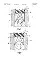
- FIG. 7is an enlarged partial view in cross-section of the seal device shown in FIGS. 5 and 6 depicting the operation of the seal device when the fluid contained within the flow line is in a hydrostatic state;
- FIG. 8is an enlarged partial view in cross-section of the seal device shown in FIGS. 5 and 6 depicting the operation of the seal device when the fluid contained within the flow line is in a hydrodynamtic state;
- FIG. 9is an enlarged partial view in cross-section of a seal device according to a second exemplary embodiment of the present invention in a relaxed state and showing a seal jacket element fabricated from a polymer material;
- FIG. 10is an enlarged partial view in cross-section showing the second exemplary embodiment of the present invention shown in FIG. 9 interposed and compressed into a compressed state between joined pieces of the flow line;
- FIG. 11is an enlarged partial view in cross-section showing a third exemplary embodiment of the present invention similar to FIG. 4 but without a spacer element and shown in a compressed state;
- FIG. 12is an enlarged partial view in cross-section similar to FIG. 11 but without a V-shaped spring element
- FIG. 13is an enlarged partial view in cross-section of a fifth exemplary embodiment of the present invention employing a elastomeric spacer element and a polymeric seal jacket element;
- FIG. 14is an enlarged partial view in cross-section of a sixth exemplary embodiment of the present invention having an elastomeric spacer element which matably receives a seal jacket element fabricated from metal;
- FIG. 15is an enlarged partial view in cross-section of a seventh exemplary embodiment of the present invention showing a spring element as a pair of bellville springs and a seal jacket element as a polymeric membrane;
- FIG. 16is an enlarged partial view in cross-section of an eighth exemplary embodiment of the present invention showing an elastomeric spacer element configured to define a channel opening and a seal jacket element as a polymeric membrane;
- FIG. 17is an enlarged partial view in cross-section of a ninth exemplary embodiment of the present invention showing an inner seal retainer portion of an outer seal retainer configured to define a channel opening and a seal jacket element as a polymeric membrane;
- FIG. 18is an enlarged partial view in cross-section of a tenth exemplary embodiment of the present invention showing a spacer element as an elastomeric O-ring and a seal jacket element as a polymeric material;
- FIG. 19is an enlarged partial view in cross-section of an eleventh exemplary embodiment of the present invention showing an inner seal member which is extruded from an elastomeric material and configured to define a substantially V-shaped channel opening;
- FIG. 20is an enlarged partial view in cross-section of a twelfth exemplary embodiment of the present invention showing an inner seal member extruded from an elastomeric material and configured to define a skewed V-shaped channel opening;
- FIG. 21is an enlarged partial view in cross-section of a thirteenth exemplary embodiment of the present invention showing an inner seal member extruded from an elastomeric material and configured to defined a truncated and skewed V-shaped channel opening;
- FIG. 22is an enlarged partial view in cross-section of a fourteenth exemplary embodiment of the present invention showing a seal jacket element fabricated from an elastomeric extrusion molded around a spring element;
- FIG. 23is an enlarged partial view in cross-section of a fifteenth exemplary embodiment of the present invention showing an inner seal member molded around a spring element;
- FIG. 24is an enlarged partial view in cross-section of a sixteenth exemplary embodiment of the present invention showing a seal jacket element as an elastomeric extrusion and a spring element formed as an elastomeric O-ring in combination the configuration of a channel opening;
- FIG. 25is an enlarged partial view in cross-section of a seventeenth exemplary embodiment of the present invention showing a polymeric seal jacket element and a spring element as an elastomeric O-ring coated in a polymeric material which form in combination the configuration of a channel opening;
- FIG. 26is an enlarged partial view in cross-section of an eighteenth exemplary embodiment of the present invention showing a seal jacket element fabricated from a polymeric material and a spring element which form in combination the configuration of the channel opening;
- FIG. 27is an enlarged partial view in cross-section of a nineteenth exemplary embodiment of the present invention showing a seal jacket element fabricated from a polymeric material with an O-ring and with an inner seal retainer member that forms the channel opening;
- FIG. 28is an enlarged partial view in cross-section of a twentieth exemplary embodiment of the present invention showing a seal jacket element fabricated from a polymeric material with an O-ring and with an inner seal retainer member that forms the channel opening with the inner seal retainer member having radial passageways therethrough; and
- FIG. 29is an enlarged partial view in cross-section of a twenty-first embodiment of the present invention that is similar to FIG. 27 but with the inner seal retainer member sized to float even when the seal device is in the compressed state.
- the present inventiongenerally concerns seal devices which may be inserted between joint connections in a flow line system and is specifically directed to seal devices which are corrosion resistant and affected by hydrodynamic and hydrostatic forces of the fluid contained in a flow line system. It should be appreciated, however, that the seal device technology described herein could be used for seal device applications other than in flow lines. While the exemplary embodiments of the present invention are further described with respect to an annular seal device to be interposed and compressed between flanged-end connections of adjacent pipe sections, it should be understood at the outset of this description that the features and benefits encompassed in the present invention may be applied to seal devices having other configurations, other flow line applications and other joint connections.
- seal device of the present inventionmay be applied to a seal device to be interposed and compressed between an oil pan and block of an internal combustion engine.
- seal deviceto be interposed and compressed between an oil pan and block of an internal combustion engine.
- One of ordinary skill in the artshould readily be able to implement the features and benefits described with respect to the present invention in numerous situations requiring the use of seal devices.
- FIGS. 1-8A first exemplary embodiment of an annular seal device according to the present invention is generally shown in FIGS. 1-8.
- the seal deviceWhen not in use, that is, in a relaxed state, the seal device is best shown in FIGS. 1-4.
- the seal deviceWhen in use, that is, in a compressed state the seal device is best shown in FIGS. 5-6.
- FIGS. 7 and 8illustrate a general theory how the seal device of the present invention operates when compressed and when fluid is present in the flow line.
- seal device 10has a shape of an annulus having a circular central opening 12 which extends therethrough about a central axis "C" which also represents the direction of fluid flow.
- annular seal device 10comprises an annular inner seal member 14 and an annular outer seal retainer member 16.
- Annular inner seal member 14is W-shaped in cross-section and thus has a channel structure 18 that provides a channel opening 20 which faces circular central opening 12 and extends therearound.
- Annular inner seal member 14also is configured to provide a pair of lip structures 21 and 23 which are disposed opposite of each other and extend around an inner annular portion of annular inner seal member 14.
- Annular outer seal retainer member 16surrounds annular inner seal member 14.
- annular outer seal retainer member 16has a select outer seal retainer member thickness "t 1 " and annular inner seal member 14 has a select inner seal member thickness "t 2 " which is greater than the outer seal retainer member thickness "t 1 " when in the relaxed state.
- the inner seal member thickness "t' 2 "is substantially equal to the outer seal retainer member thickness "t 1 " when interposed and compressed into a compressed state between the joined pieces in the flow line.
- the annular inner seal member 14includes an outer seal portion 22 and annular outer seal retainer member 16 includes an inner seal retainer portion 24 which is adapted to contact outer seal portion 22 of annular inner seal retainer member 14.
- Annular inner seal member 14 in this first exemplary embodimentincludes a seal jacket element 26, a spring element 28 and a spacer element 30.
- Seal jacket element 26is adapted to grip inner seal retainer portion 24 of outer seal retainer member 16.
- seal jacket element 26is fabricated from a metal or metal alloy. If the first exemplary embodiment of the seal device 10 is to be used in a highly corrosive environment, a corrosion-resistant metal such as stainless steel, stainless steel alloys, titanium or titanium alloys can be used.
- Spring element 28is disposed within and around seal jacket element 26 and is operative to bias seal jacket element 26 coaxially outwardly.
- Spring element 28is configured in cross section as a V-shape.
- Spacer element 30is disposed within and annularly around seal jacket element 26.
- Spacer element 30has a first side 32 which is adapted to receive a spring vertex portion 34 of V-shaped spring element 28.
- Spacer element 30has a second side 36 which is positioned opposite first side 32 of spacer element 30 and is adapted to abut annular inner seal retainer portion 24 of annular outer seal retainer member 16.
- Spacer element 30is sized to provide a resilient force coaxially outwardly against annular inner seal member 14 when compressed.
- Annular seal device 10is adapted to be interposed and compressed between joined pieces in a flow line that is operative to convey a flowing fluid.
- annular seal device 10is shown in FIG. 5 as being interposed in a flanged-end connections between two adjacent sections of pipe.
- a first section of pipe 38has a first annular flange 40 which is adapted to be placed in opposed, facing relation with a second annular flange 42 of a second section of pipe 44.
- First section of pipe 38has an interior passage way 46 which is axially aligned with a second interior passageway 48 of second section of pipe 44.
- First annular flange 40is provided with a plurality of bolt openings 50 which axially align with bolt openings 52 of second annular flange 42 in order to receive connecting tie-rods or bolts 54 which, in turn, receive nuts 56 to compressively join first and second sections of pipe 38 and 44 together.
- annular seal device 10is adapted to be compressed between the first and second annular flanges 40 and 42 so as to seal the joint between first and second sections of pipe 38 and 44 thereby preventing leakage of the fluid contained in the flow line.
- circular central opening 12 of annular seal device 10is sized to similarly align with first and second interior passageways 46 and 48 to permit the fluid to flow therethrough.
- Annular inner seal member 14 and annular outer seal retainer member 16are sized and adapted to seal a space between joined pieces of pipe to allow fluid to flow therethrough without leakage. Additionally, annular inner seal member 14 is operative to prevent contact of the fluid with annular outer seal retainer member 16 when interposed and compressed between joined pieces of pipe.
- outer seal retainer member 16be fabricated from a corrosion resistant material when the annular seal device 10 is used in a highly corrosive environment. It is preferred, however, that outer seal retainer member 16 be fabricated from a rigid material selected from a group of materials consisting of metal and glass-reinforced epoxy which resist compression forces.
- annular outer seal retainer member 16acts as a compression limiter so that regardless of the amount of torque applied to nuts 56 on bolts 54, over-torqueing will not destroy the sealing properties of annular inner seal member 14. Therefore, one ordinary skill in the art would appreciate that, with reference to FIG. 6, inner seal member thickness "t' 2 " becomes substantially equal to outer seal retainer member thickness "t 1 " when annular seal device 10 is interposed and compressed between the joined pieces in the flow line.
- each of lips 21 and 23operates to apply a sealing force against the joined pieces, i.e. first and second circular flanges 40 and 42 respectively, when annular seal device 10 is interposed and compressed therebetween.
- This sealing forceis generated in three ways. First, compressing annular inner seal member 14 from its greater thickness "t 2 " to its lesser thickness "t' 2 " generates a resilient sealing force at the lips 21 and 23 against the joint pieces. Second, spring element 28 which is resiliently biased coaxially outwardly has also been compressed which, in turn, applies yet a supplemental sealing force to the pair of lips 21 and 23 against first and second circular flanges 40 and 42 respectively. Finally, any radially outward pressure from the fluid carried by the flow line will exert an axial component pressing lips 21 and 23 against the flanges of the joined pieces.
- annular seal device 10any requirement of precision in the torque used to compress annular seal device 10 between joined pieces of pipe are now less critical because the outer seal retainer member 16 is fabricated from a rigid material that, in practice, limits the amount of compression force on annular inner seal member 14. Also, because annular seal device 10 deforms mechanically as well as within its inherent modulus of elasticity characteristics, it is expected that annular seal device 10 can be re-used without loss of its performance. Additionally, since annular seal device 10 employs both mechanical resilient properties as well as inherent modulus of elasticity properties of the material, it is believed that annular seal device 10 could be unaffected by cycles of expansion and contraction caused by fluctuations of temperature and/or pressure.
- FIGS. 9 and 10A second exemplary embodiment of an annular seal device 210 of the present invention is shown in FIGS. 9 and 10.
- An inner seal retainer portion 224includes a first pair of spaced apart grooves 258 and 260 which extends circumferentially along a first side of inner seal retainer portion 224 and a second pair of spaced apart grooves 262 and 264 which extend circumferentially about a second side of inner seal retainer portion 224.
- a seal jacket element 226is W-shaped in cross-section and is fabricated from a polymeric material, such as polytetrafluorethylene, which is generally considered anti-corrosive in nature. Note that seal jacket element 226 is contoured to contact a V-shaped spring element 228 thereby defining channel opening 220.
- seal jacket element 226, which is fabricated from selected polymetric material, with spring element 228assures that radial force R generated from the fluid contained in the flow line will not cause seal jacket element 226 to expand and subsequently rupture.
- spacer element 230occupies substantially all empty space between inner seal retainer portion 224 and spring element 228.
- annular inner seal member 314includes a seal jacket element 326 fabricated from metal and a spring element 328 also fabricated from metal. A spring vertex portion 344 abuts an inner seal retainer portion 324. If this third exemplary embodiment was required for use in a highly corrosive environment, seal jacket element 326 could be fabricated from stainless steel, stainless steel alloys, titanium or titanium alloys which are also generally considered anti-corrosive metals. In a slightly corrosive or non-corrosive environment, any suitable metal compatible with the fluid can be selected.
- FIG. 12A fourth exemplary embodiment of the present invention is shown in FIG. 12.
- a seal jacket element 426 fabricated from metalgrips an inner seal retainer portion 424 of an annular outer seal retainer member 416.
- a vertex portion 466 of a channel structure 418abuts inner seal retainer portion 424, and edges 425 of channel structure 418 contact shoulders 417 of retainer member 416 when in the compressed state.
- Annular inner seal member 514includes a seal jacket element 526 fabricated from a polymeric material and a spacer element 530 which is fabricated from an elastomeric material.
- Spacer element 530has a first spacer element side 532 which is configured in a manner to define channel structure 518 which is formed to define channel opening 520.
- Annular inner seal element 514also includes a pair of lips 521 and 523.
- FIG. 14A sixth exemplary embodiment of an annular seal device 610 is shown in FIG. 14.
- An annular inner seal member 614includes a seal jacket element 626 fabricated from metal, and a thick V-shaped spacer element 630 is fabricated from an elastomeric material.
- An inner seal retainer portion 624 of an annular outer seal retainer member 616is formed to have a groove 617 configured similarly to vertex portion 631 of spacer element 630 so that spacer element 630 is matably received therein.
- FIG. 15A seventh exemplary embodiment of an annular seal device 710 of the present invention is shown in FIG. 15.
- An annular inner seal member 714is shown to include a membrane 768 and a pair of bellville springs 770 and 772.
- a common bellvilles 770 or 772are frustoconical washer-like devices.
- the pair of bellvilles 770 and 772are in contact at respective outer peripheral edges 774 and are operative to bias membrane 768 coaxially outwardly.
- Membrane 768has an outer seal portion 722 which contacts an inner seal retainer portion 724 of annular outer seal retainer member 716.
- Channel structure 718contacts an outer surface area 776 of the pair of bellvilles 770 and 772.
- annular inner seal member 814includes a membrane 868 which is typically fabricated from a relatively thin, pliable polymeric material again such as polytetrafluroethylene and a spacer element 830 which is fabricated from an elastomeric material.
- Spacer element 830is enveloped by membrane 868.
- Spacer element 830has a first spacer element side 832 which is configured to define a channel opening 820 and has a second spacer element side 836 which is disposed opposite first spacer element side 832 and is adapted to abut an inner seal retainer portion 824 of an outer seal retainer member 816.
- FIG. 17A ninth exemplary embodiment of an annular seal device 910 is shown in FIG. 17.
- An annular inner seal member 914is a membrane 968 which is typically fabricated from a relatively thin, pliable anti-corrosive polymeric material.
- An inner seal retainer portion 924 of an annular outer seal member 916is formed to define a channel opening 920.
- a channel structure 918 of membrane 968is adapted to conform to the configuration of inner seal retainer portion 924. It may be appreciated that this embodiment eliminates the spacer element.
- FIG. 18A tenth exemplary embodiment of an annular seal device 1010 of the present invention is depicted in FIG. 18.
- a seal jacket element 1026is fabricated from a polymeric material.
- a spring element 1028is an O-ring which is fabricated from an elastomeric material. Spring element 1028 extends within and circumferentially around seal jacket element 1026.
- Channel structure 1018is located between a pair of lips 1021 and 1023 and has an arcuate central portion 1019 shaped at a radius to conform with the curvature of the circular cross-section of spring element 1028 to define a channel opening 1020.
- FIG. 19An eleventh exemplary embodiment of an annular seal device 1110 is shown in FIG. 19.
- An annular inner seal member 1114is an elastomer extrusion and has an outer extruded wall 1178.
- An inner seal retainer portion 1124 of an annular outer retainer seal member 1116includes an inner seal retainer wall 1180.
- Outer extruded wall 1178 of the elastomer extrusion and inner seal retainer wall 1180 of inner seal retainer portion 1124abut each other.
- a V-shaped structure 1118forms V-shaped channel opening 1120.
- FIG. 20A twelfth exemplary embodiment of an annular seal device 1210 of the present invention is depicted in FIG. 20.
- An annular inner seal member 1214is an elastomer extrusion similar to the annular inner seal member 1114 shown in FIG. 19. The only difference is that a channel structure 1218 forms a skewed V-shaped channel opening 1220. Lip structures 1221 and 1223 are integrally formed on inner seal member 1214.
- FIG. 21A thirteenth exemplary embodiment of an annular seal device 1310 of the present invention is depicted in FIG. 21.
- An annular inner seal member 1314is an elastomer extrusion similar to the annular inner seal member 1114 of FIG. 19 and annular seal member 1214 of FIG. 20.
- a channel structure 1318defines a skewed V-shaped channel opening 1320 which is positioned between a pair of annular walls 1382 and 1384.
- the lip structures 1321 and 1323are truncated.
- annular inner seal member 1414is an elastomer extrusion which includes a spring part 1486 adapted to be embedded in, i.e., to extend within and around, the elastomer extrusion.
- Annular inner seal member 1414is substantially V-shaped and, as a result, an inner seal retainer portion 1424 of annular outer seal retainer member 1416 is configured to receive the V-shaped elastomer extrusion in a mated relationship.
- FIG. 23A fifteenth exemplary embodiment of an annular seal device of the present invention is depicted in FIG. 23.
- An annular inner seal member 1514is an elastomer extrusion having a coil spring element 1528 embedded in the elastomer extrusion. When the elastomer extrusion is viewed in cross-section, an extruded wall 1578 forms a U-shape.
- An inner seal retainer portion 1424 of an annular outer seal retainer member 1516is adapted to matably receive the elastomer extrusion and contact extruded wall 1578.
- FIG. 24A sixteenth exemplary embodiment of an annular seal device 1610 of the present invention is depicted in FIG. 24.
- An annular inner seal member 1614is an elastomer extrusion which includes an elastomeric O-ring extending circumferentially within and around a groove 1629 in the elastomer extrusion.
- a channel structure 1618includes a pair of lips 1621 and 1623 and an arcuate portion 1686 of O-ring element 1628 which, in combination, define channel opening 1620.
- FIG. 25A seventeenth exemplary embodiment of an annular seal device 1710 of the present invention is depicted in FIG. 25.
- An annular inner seal member 1714includes a seal jacket element 1726 fabricated from a polymeric material such as polytetrafluroethylene and a spring element 1728.
- Spring element 1728is an elastomeric O-ring which is enclosed in a coating 1788 of a polymeric material such as polytetrafluroethylene to protect against corrosive fluids.
- a channel structure 1718includes a pair of lips 1721, 1723 and a portion 1786 of spring element 1728 which, in combination, define channel opening 1720.
- An eighteenth exemplary embodiment of an annular seal device 1810is depicted in FIG. 26.
- An annular inner seal member 1814includes a seal jacket element 1826 fabricated from an anti-corrosive polymeric material, and a spring element 1828 which is a V-shaped finger spring. Alternatively, spring element 1828 could be configured in cross-section as a U-shape.
- Seal jacket element 1826is adapted to receive spring element 1828 which extends within and circumferentially about seal jacket element 1826.
- a pair of shoulders 1890 and 1892are operative to retain a pair of inner peripheral edges 1894 and 1896 of spring element 1828.
- a channel opening 1820is substantially defined by an inner arcuate surface 1898 of spring element 1828 that extends circumferentially therearound. If this exemplary embodiment of the present invention is to be used in a corrosive environment, spring element 1828 is fabricated from a corrosive resistant material such as stainless steel, stainless steel alloys, titanium or titanium alloys.
- an inner retainer memberas shown in FIGS. 27-29 can be used to prevent the polymeric seal jacket element from flowing into the channel opening when placed in a high temperature environment.
- FIG. 27A nineteenth exemplary embodiment of an annular seal device 1910 interposed and compressed between a first annular flange 1940 and a second annular flange 1942 is shown in FIG. 27.
- An annular inner seal member 1914includes a polymeric seal jacket element 1926, a spring element 1928 being an elastomeric O-ring and an inner retainer member 1981.
- Inner retainer member 1981has a first inner retainer side 1983 which is adapted to be received into a channel opening 1920 and operative to contact lip structures 1921 and 1923.
- Inner retainer member 1981has a second inner retainer side 1985 which is opposite first inner retainer side 1983 and is oriented toward a central opening 1912. It is preferred that inner retainer member 1981 is annular in configuration.
- FIG. 28A twentieth exemplary embodiment of an annular seal device 2010 interposed and compressed between a first annular flange 2040 and a second annular flange 2042 is shown in FIG. 28.
- An annular inner seal member 2014includes a polymeric seal jacket element 2026, a spring element 2028 being an elastomeric O-ring and an inner retainer member 2081, which is substantially similar to annular seal device 1910 shown in FIG. 27.
- a difference between these two exemplary embodimentsis that a plurality of spaced apart, radially extending passageways, such as passageway 2087 extend between a first inner retainer side 2083 and a second inner retainer side 2085.
- these passagewaysare equiangularly spaced around inner retainer member 2081, and the purpose of these passageways is to allow fluid communication between a channel opening 2020 and a central opening 2012.
- FIG. 29A twenty-first exemplary embodiment of an annular seal device 2110 interposed and compressed between a first annular flange 2140 and a second annular flange 2142 is shown in FIG. 29.
- An annular inner seal member 2114includes a polymeric seal jacket element 2126, a spring element 2128 being an elastomeric O-ring and an inner retainer member 2181. Note that although annular inner seal member 2114 is compressed between first and second annular flanges 2140 and 2142, inner retainer member 2181 is permitted to "float” therebetween. Permitting inner retainer member 2181 to "float" between first and second annular flanges 2140 and 2142 allows the fluid to communicate between a channel opening 2120 and a central opening 2112.
- a seal devicecan be fabricated in accordance with specific performance requirements depending upon, inter alia, temperature, pressure and corrosive nature of the fluid contained in the flow line.
- corrosion resistant materialssuch as polymers e.g., Polytetrafluorethylene, stainless steel, stainless steel alloys, titanium or titanium alloys can be used.
- a specific one or perhaps several of the above-described exemplary embodimentsmay be optimally suitable for that particular application.
Landscapes
- Engineering & Computer Science (AREA)
- General Engineering & Computer Science (AREA)
- Mechanical Engineering (AREA)
- Gasket Seals (AREA)
Abstract
Description
Claims (45)
Priority Applications (1)
| Application Number | Priority Date | Filing Date | Title |
|---|---|---|---|
| US08/110,562US5518257A (en) | 1993-08-23 | 1993-08-23 | Seal device for flow line applications |
Applications Claiming Priority (1)
| Application Number | Priority Date | Filing Date | Title |
|---|---|---|---|
| US08/110,562US5518257A (en) | 1993-08-23 | 1993-08-23 | Seal device for flow line applications |
Publications (1)
| Publication Number | Publication Date |
|---|---|
| US5518257Atrue US5518257A (en) | 1996-05-21 |
Family
ID=22333701
Family Applications (1)
| Application Number | Title | Priority Date | Filing Date |
|---|---|---|---|
| US08/110,562Expired - LifetimeUS5518257A (en) | 1993-08-23 | 1993-08-23 | Seal device for flow line applications |
Country Status (1)
| Country | Link |
|---|---|
| US (1) | US5518257A (en) |
Cited By (66)
| Publication number | Priority date | Publication date | Assignee | Title |
|---|---|---|---|---|
| WO1997044602A1 (en)* | 1996-05-17 | 1997-11-27 | Beckswift Limited | A pipe joint and a gasket therefor |
| US5713582A (en)* | 1997-01-03 | 1998-02-03 | Eg&G Pressure Science, Inc. | Seal retainer |
| US5722668A (en)* | 1994-04-29 | 1998-03-03 | Applied Materials, Inc. | Protective collar for vacuum seal in a plasma etch reactor |
| US5730448A (en)* | 1997-01-03 | 1998-03-24 | Eg&G Pressure Science, Inc. | Seal retainer plate |
| US5735532A (en)* | 1997-01-03 | 1998-04-07 | Eg&G Pressure Science, Inc. | Seal compression limiting retainer |
| US5735533A (en)* | 1997-01-03 | 1998-04-07 | Eg&G Pressure Science, Inc. | Cavity depth increasing retainer |
| WO1998045638A1 (en)* | 1997-04-08 | 1998-10-15 | Kohn Gary A | Dielectric gasket |
| US5851109A (en)* | 1997-01-22 | 1998-12-22 | Warren Rupp, Inc. | Spacer and shim assembly for fluid powered diaphragm pumps |
| EP0915273A3 (en)* | 1997-11-04 | 2000-01-19 | Penberthy, Inc. | Dual sealing gasket |
| US6092811A (en)* | 1996-04-30 | 2000-07-25 | Jamco Products, Llc | Hybrid gasket |
| US6241253B1 (en)* | 1998-06-08 | 2001-06-05 | Interface Solutions, Inc. | Edge coated soft gasket |
| US6247703B1 (en)* | 1997-08-29 | 2001-06-19 | Interface Solutions, Inc. | High-pressure compression-failure resistant and high sealing gasket |
| US6268020B1 (en) | 1997-08-29 | 2001-07-31 | Interface Solutions, Inc. | Method of fabricating high sealing gaskets |
| US6340162B1 (en)* | 1999-08-13 | 2002-01-22 | Trw Inc. | Seal for integral power steering gear |
| US6402159B1 (en) | 1997-04-08 | 2002-06-11 | Gary A. Kohn | Dielectric gasket |
| US20030071424A1 (en)* | 2001-10-11 | 2003-04-17 | Colin Chen | Spring back fire ring |
| US6565124B2 (en) | 1996-05-17 | 2003-05-20 | Beckswift Limited | Pipe joint and a gasket therefor |
| US6626439B1 (en) | 1997-08-29 | 2003-09-30 | Interface Solutions, Inc. | Edge coated gaskets and method of making same |
| US6669205B2 (en) | 2001-03-28 | 2003-12-30 | Parker-Hannifin Corporation | Retainer gasket with pressure relief vents |
| US6695357B2 (en) | 2001-03-28 | 2004-02-24 | Parker-Hannifin Corporation | Threaded pipe connection having a retainer gasket with pressure relief vents |
| US6702296B2 (en) | 2000-07-26 | 2004-03-09 | Interface Solutions, Inc. | Gaskets with selectively positioned seal enhancement zones |
| US6733015B2 (en)* | 2000-03-06 | 2004-05-11 | Interface Solutions, Inc. | Gaskets with controlled flange surface adhesion properties |
| US20040108204A1 (en)* | 1999-05-10 | 2004-06-10 | Ineos Chlor Limited | Gasket with curved configuration at peripheral edge |
| US6776439B2 (en) | 1999-11-18 | 2004-08-17 | David E. Albrecht | Flange plates for fluid port interfaces |
| US20040201180A1 (en)* | 2002-04-19 | 2004-10-14 | Shah Kanu G. | Exhaust pipe flange ring gasket |
| US20040239047A1 (en)* | 2001-08-16 | 2004-12-02 | Kent Edwin J. | Composite fuel permeation barrier seal |
| US20050012279A1 (en)* | 2003-07-15 | 2005-01-20 | Hodges James W. | Gasket having an inner edge with coined angles and method of manufacture |
| US20050014368A1 (en)* | 2002-06-21 | 2005-01-20 | Junichiro Yoshioka | Substrate holder and plating apparatus |
| US20050046121A1 (en)* | 2003-08-26 | 2005-03-03 | Jones Jay M. | Retainer gasket construction |
| US20050044689A1 (en)* | 2003-08-26 | 2005-03-03 | Yetter William P. | Retainer gasket construction |
| US20050194750A1 (en)* | 2004-03-05 | 2005-09-08 | Wallace Thomas C. | Seal device |
| US20060038357A1 (en)* | 2004-08-23 | 2006-02-23 | Kamibayashiyama Julian F | Wedging retainer gasket construction |
| US20070001404A1 (en)* | 2005-07-04 | 2007-01-04 | Nichias Corproation | O-ring and clamp-type joint for vacuum apparatus |
| US20070001403A1 (en)* | 2005-07-04 | 2007-01-04 | Nichias Corporation | Outer ring and clamp-type joint for vacuum apparatus |
| US20080029966A1 (en)* | 2005-06-14 | 2008-02-07 | More Dominick G | Seal assembly |
| WO2008141388A1 (en)* | 2007-05-22 | 2008-11-27 | Simmons Group Investments Pty Ltd | Sealed joint assembly |
| US20090072495A1 (en)* | 2006-09-27 | 2009-03-19 | Wilhelm Kullen | Sealing system, in particular for attachment connections on flow paths for hot gases |
| US20100052268A1 (en)* | 2006-04-25 | 2010-03-04 | Fred Georg Schroeder | Block fitting and seal structure |
| US20100059988A1 (en)* | 2007-08-27 | 2010-03-11 | Nowla Engineering Co., Ltd. | Loose flange pipe joint |
| US20100123292A1 (en)* | 2008-11-20 | 2010-05-20 | Toyota Jidosha Kabushiki Kaisha | Gasket |
| US20110072634A1 (en)* | 2005-04-08 | 2011-03-31 | Kamibayashiyama Julian F | Wedging retainer gasket construction |
| US20110101623A1 (en)* | 2008-06-21 | 2011-05-05 | Rolf Prehn | Flat seal |
| US20110156352A1 (en)* | 2009-12-24 | 2011-06-30 | Stephen Peter Bond | Gasket |
| US20130020768A1 (en)* | 2009-12-09 | 2013-01-24 | Robert Bosch Gmbh | Arrangement and method for sealing off a joint area between a first joint partner and a second joint partner |
| US20130099451A1 (en)* | 2011-10-25 | 2013-04-25 | Judson B. Estes | Self-sealing gasket |
| WO2014074387A1 (en)* | 2012-11-12 | 2014-05-15 | Vetco Gray Inc. | Shrinkage compensated seal assembly and related methods |
| US20140312570A1 (en)* | 2013-04-18 | 2014-10-23 | Bal Seal Engineering, Inc. | Interlocking face seal assemblies and related methods |
| US20150023764A1 (en)* | 2011-12-12 | 2015-01-22 | Carl Freudenberg Kg | Seal, screw connection having the seal, and use thereof |
| US9016675B2 (en)* | 2012-07-06 | 2015-04-28 | Asm Technology Singapore Pte Ltd | Apparatus and method for supporting a workpiece during processing |
| US20160040810A1 (en)* | 2014-08-08 | 2016-02-11 | Rohr, Inc. | Bolted duct joints |
| US9464718B2 (en)* | 2015-03-13 | 2016-10-11 | Kuk Il Inntot Co., Ltd. | Gasket and the manufacturing method thereof |
| US20170059041A1 (en)* | 2015-08-28 | 2017-03-02 | Doosan Infracore Co., Ltd. | Dust preventing seal and construction machine having the same |
| RU169119U1 (en)* | 2016-10-26 | 2017-03-03 | Федеральное государственное бюджетное учреждение "Национальный исследовательский центр "Курчатовский институт" | SUPER HIGH VACUUM SEALING CONNECTION |
| US9593430B2 (en) | 2002-07-22 | 2017-03-14 | Ebara Corporation | Electrochemical deposition method |
| US20180058616A1 (en)* | 2016-08-25 | 2018-03-01 | Marc Rowley | Non-metallic high pressure high temperature high chemical compatibility flange isolation gasket |
| KR20180047095A (en)* | 2016-10-31 | 2018-05-10 | 주식회사 포스코건설 | Gasket apparatus for self sealing |
| US20180299044A1 (en)* | 2016-10-05 | 2018-10-18 | Garlock Pipeline Technologies, Inc. | Gasket with electrical isolating coatings |
| US10125872B2 (en) | 2011-08-18 | 2018-11-13 | Bal Seal Engineering, Inc. | Reciprocating seal for high pulsating pressure |
| JP2018533702A (en)* | 2015-11-11 | 2018-11-15 | グリーン, ツイード テクノロジーズ, インコーポレイテッド | Seal ring and seal ring assembly for high temperature end use applications |
| DE102019105984B3 (en)* | 2019-03-08 | 2020-02-27 | Dr. Ing. H.C. F. Porsche Aktiengesellschaft | Sealing ring for connecting two fluid-carrying elements, cooling system with such a sealing ring for a traction battery of an electrically operated vehicle and method for producing such a cooling system |
| US10753521B1 (en) | 2019-05-31 | 2020-08-25 | Advance Products & Systems, Llc | Inner diameter seal gasket |
| US11129624B2 (en) | 2009-12-22 | 2021-09-28 | Cook Medical Technologies Llc | Medical devices with detachable pivotable jaws |
| WO2022152811A1 (en)* | 2021-01-15 | 2022-07-21 | General Electric Technology Gmbh | Improved compression sealing gasket and sealing system |
| US20230133675A1 (en)* | 2016-10-05 | 2023-05-04 | Garlock Pipeline Technologies, Inc. | Gasket with electrical isolating coatings |
| US12070224B2 (en) | 2009-12-22 | 2024-08-27 | Cook Medical Technologies Llc | Medical devices with detachable pivotable jaws |
| US12422067B1 (en)* | 2023-07-31 | 2025-09-23 | Michael Gulyansky | Methods structures devices assemblies systems and functionally associated machine executable instructions for industrial processing of material |
Citations (8)
| Publication number | Priority date | Publication date | Assignee | Title |
|---|---|---|---|---|
| US2196953A (en)* | 1938-04-04 | 1940-04-09 | Flexitallic Gasket Co Inc | Gasket pressure control |
| US2339479A (en)* | 1942-12-28 | 1944-01-18 | Frederick W Goetze | Composite gasket |
| US2827320A (en)* | 1955-11-30 | 1958-03-18 | Gen Electric | Seal |
| US3302953A (en)* | 1963-02-25 | 1967-02-07 | Clarence O Glasgow | Gasket ring and conduit coupling |
| DE2048569A1 (en)* | 1970-10-02 | 1972-04-06 | Kempchen & Co Gmbh | poetry |
| US3857572A (en)* | 1973-10-18 | 1974-12-31 | Pressure Science Inc | E-ring seal assembly |
| US4348032A (en)* | 1981-03-19 | 1982-09-07 | The Fluorocarbon Company | Head gasket having resilient seal with Belleville springs |
| US4585239A (en)* | 1984-09-05 | 1986-04-29 | Nicholson Terence P | Channeled ring seals with spring rings |
- 1993
- 1993-08-23USUS08/110,562patent/US5518257A/ennot_activeExpired - Lifetime
Patent Citations (8)
| Publication number | Priority date | Publication date | Assignee | Title |
|---|---|---|---|---|
| US2196953A (en)* | 1938-04-04 | 1940-04-09 | Flexitallic Gasket Co Inc | Gasket pressure control |
| US2339479A (en)* | 1942-12-28 | 1944-01-18 | Frederick W Goetze | Composite gasket |
| US2827320A (en)* | 1955-11-30 | 1958-03-18 | Gen Electric | Seal |
| US3302953A (en)* | 1963-02-25 | 1967-02-07 | Clarence O Glasgow | Gasket ring and conduit coupling |
| DE2048569A1 (en)* | 1970-10-02 | 1972-04-06 | Kempchen & Co Gmbh | poetry |
| US3857572A (en)* | 1973-10-18 | 1974-12-31 | Pressure Science Inc | E-ring seal assembly |
| US4348032A (en)* | 1981-03-19 | 1982-09-07 | The Fluorocarbon Company | Head gasket having resilient seal with Belleville springs |
| US4585239A (en)* | 1984-09-05 | 1986-04-29 | Nicholson Terence P | Channeled ring seals with spring rings |
Non-Patent Citations (2)
| Title |
|---|
| Exhibit "A"-Graphite-Filled, Spiral-Wound Seal, Houston, Texas no date of author available. |
| Exhibit A Graphite Filled, Spiral Wound Seal, Houston, Texas no date of author available.* |
Cited By (116)
| Publication number | Priority date | Publication date | Assignee | Title |
|---|---|---|---|---|
| US5722668A (en)* | 1994-04-29 | 1998-03-03 | Applied Materials, Inc. | Protective collar for vacuum seal in a plasma etch reactor |
| US6092811A (en)* | 1996-04-30 | 2000-07-25 | Jamco Products, Llc | Hybrid gasket |
| WO1997044602A1 (en)* | 1996-05-17 | 1997-11-27 | Beckswift Limited | A pipe joint and a gasket therefor |
| US6565124B2 (en) | 1996-05-17 | 2003-05-20 | Beckswift Limited | Pipe joint and a gasket therefor |
| AU728321B2 (en)* | 1996-05-17 | 2001-01-04 | Beckswift Limited | A pipe joint and a gasket therefor |
| US5730448A (en)* | 1997-01-03 | 1998-03-24 | Eg&G Pressure Science, Inc. | Seal retainer plate |
| US6015152A (en)* | 1997-01-03 | 2000-01-18 | Eg&G Pressure Science, Inc. | Seal retainer having an indicator |
| US5735533A (en)* | 1997-01-03 | 1998-04-07 | Eg&G Pressure Science, Inc. | Cavity depth increasing retainer |
| US5735532A (en)* | 1997-01-03 | 1998-04-07 | Eg&G Pressure Science, Inc. | Seal compression limiting retainer |
| US5713582A (en)* | 1997-01-03 | 1998-02-03 | Eg&G Pressure Science, Inc. | Seal retainer |
| US5851109A (en)* | 1997-01-22 | 1998-12-22 | Warren Rupp, Inc. | Spacer and shim assembly for fluid powered diaphragm pumps |
| WO1998045638A1 (en)* | 1997-04-08 | 1998-10-15 | Kohn Gary A | Dielectric gasket |
| US6402159B1 (en) | 1997-04-08 | 2002-06-11 | Gary A. Kohn | Dielectric gasket |
| US6268020B1 (en) | 1997-08-29 | 2001-07-31 | Interface Solutions, Inc. | Method of fabricating high sealing gaskets |
| US20040007828A1 (en)* | 1997-08-29 | 2004-01-15 | Interface Solutions, Inc. | Edge coated gaskets and method of making same |
| US6247703B1 (en)* | 1997-08-29 | 2001-06-19 | Interface Solutions, Inc. | High-pressure compression-failure resistant and high sealing gasket |
| US6923998B2 (en) | 1997-08-29 | 2005-08-02 | Interface Solutions, Inc. | Edge coated gaskets and method of making same |
| US6626439B1 (en) | 1997-08-29 | 2003-09-30 | Interface Solutions, Inc. | Edge coated gaskets and method of making same |
| US20030230856A1 (en)* | 1997-08-29 | 2003-12-18 | Interface Solutions, Inc. | Edge coated gaskets and method of making same |
| US7278639B2 (en) | 1997-08-29 | 2007-10-09 | Interface Solutions, Inc. | Edge coated gaskets and method of making same |
| EP0915273A3 (en)* | 1997-11-04 | 2000-01-19 | Penberthy, Inc. | Dual sealing gasket |
| US6241253B1 (en)* | 1998-06-08 | 2001-06-05 | Interface Solutions, Inc. | Edge coated soft gasket |
| US7363110B2 (en)* | 1999-05-10 | 2008-04-22 | Ineos Chlor Enterprises Limited | Gasket with curved configuration at peripheral edge |
| US20070187906A1 (en)* | 1999-05-10 | 2007-08-16 | Ineos Chlor Limited | Gasket with curved configuration at peripheral edge |
| US20040108204A1 (en)* | 1999-05-10 | 2004-06-10 | Ineos Chlor Limited | Gasket with curved configuration at peripheral edge |
| US6340162B1 (en)* | 1999-08-13 | 2002-01-22 | Trw Inc. | Seal for integral power steering gear |
| US6776439B2 (en) | 1999-11-18 | 2004-08-17 | David E. Albrecht | Flange plates for fluid port interfaces |
| US20040239045A1 (en)* | 1999-11-18 | 2004-12-02 | Albrecht David E. | Flange plates for fluid port interfaces |
| US6733015B2 (en)* | 2000-03-06 | 2004-05-11 | Interface Solutions, Inc. | Gaskets with controlled flange surface adhesion properties |
| US6702296B2 (en) | 2000-07-26 | 2004-03-09 | Interface Solutions, Inc. | Gaskets with selectively positioned seal enhancement zones |
| US7014193B2 (en) | 2000-07-26 | 2006-03-21 | Interface Solutions, Inc. | Gasket with selectively positioned seal enhancement zones |
| US20040140627A1 (en)* | 2000-07-26 | 2004-07-22 | Interface Solutions, Inc. | Gasket with selectively positioned seal enhancement zones |
| US6669205B2 (en) | 2001-03-28 | 2003-12-30 | Parker-Hannifin Corporation | Retainer gasket with pressure relief vents |
| US6695357B2 (en) | 2001-03-28 | 2004-02-24 | Parker-Hannifin Corporation | Threaded pipe connection having a retainer gasket with pressure relief vents |
| US20040239047A1 (en)* | 2001-08-16 | 2004-12-02 | Kent Edwin J. | Composite fuel permeation barrier seal |
| US20100019455A1 (en)* | 2001-08-16 | 2010-01-28 | Kent Jr Edwin J | Composite fuel permeation barrier seal |
| US6719301B2 (en)* | 2001-10-11 | 2004-04-13 | Dana Corporation | Spring back fire ring |
| US20030071424A1 (en)* | 2001-10-11 | 2003-04-17 | Colin Chen | Spring back fire ring |
| US20040201180A1 (en)* | 2002-04-19 | 2004-10-14 | Shah Kanu G. | Exhaust pipe flange ring gasket |
| US8936705B2 (en) | 2002-06-21 | 2015-01-20 | Ebara Corporation | Electrochemical deposition apparatus |
| US8337680B2 (en) | 2002-06-21 | 2012-12-25 | Ebara Corporation | Substrate holder and plating apparatus |
| US20110127159A1 (en)* | 2002-06-21 | 2011-06-02 | Junichiro Yoshioka | Substrate holder and plating apparatus |
| US7901551B2 (en) | 2002-06-21 | 2011-03-08 | Ebara Corporation | Substrate holder and plating apparatus |
| US7601248B2 (en)* | 2002-06-21 | 2009-10-13 | Ebara Corporation | Substrate holder and plating apparatus |
| US9388505B2 (en) | 2002-06-21 | 2016-07-12 | Ebara Corporation | Electrochemical deposition method |
| US9506162B2 (en) | 2002-06-21 | 2016-11-29 | Ebara Corporation | Electrochemical deposition method |
| US20050014368A1 (en)* | 2002-06-21 | 2005-01-20 | Junichiro Yoshioka | Substrate holder and plating apparatus |
| US20100000858A1 (en)* | 2002-06-21 | 2010-01-07 | Junichiro Yoshioka | Substrate Holder and Plating Apparatus |
| US9624596B2 (en) | 2002-07-22 | 2017-04-18 | Ebara Corporation | Electrochemical deposition method |
| US9593430B2 (en) | 2002-07-22 | 2017-03-14 | Ebara Corporation | Electrochemical deposition method |
| US20050012279A1 (en)* | 2003-07-15 | 2005-01-20 | Hodges James W. | Gasket having an inner edge with coined angles and method of manufacture |
| US20050044689A1 (en)* | 2003-08-26 | 2005-03-03 | Yetter William P. | Retainer gasket construction |
| US7401404B2 (en) | 2003-08-26 | 2008-07-22 | Parker-Hannifin Corporation | Retainer gasket construction |
| US20050046121A1 (en)* | 2003-08-26 | 2005-03-03 | Jones Jay M. | Retainer gasket construction |
| US20050194750A1 (en)* | 2004-03-05 | 2005-09-08 | Wallace Thomas C. | Seal device |
| WO2005086747A3 (en)* | 2004-03-05 | 2009-04-02 | Corrosion Control Corp | Seal device |
| US20060038357A1 (en)* | 2004-08-23 | 2006-02-23 | Kamibayashiyama Julian F | Wedging retainer gasket construction |
| US20110072634A1 (en)* | 2005-04-08 | 2011-03-31 | Kamibayashiyama Julian F | Wedging retainer gasket construction |
| US20080029966A1 (en)* | 2005-06-14 | 2008-02-07 | More Dominick G | Seal assembly |
| US8764021B2 (en)* | 2005-06-14 | 2014-07-01 | Parker-Hannifin Corporation | Seal assembly |
| US7722053B2 (en)* | 2005-07-04 | 2010-05-25 | Nichias Corporation | Outer ring and clamp-type joint for vacuum apparatus |
| US20070001403A1 (en)* | 2005-07-04 | 2007-01-04 | Nichias Corporation | Outer ring and clamp-type joint for vacuum apparatus |
| US7520511B2 (en)* | 2005-07-04 | 2009-04-21 | Nichias Corporation | O-ring and clamp-type joint for vacuum apparatus |
| US20070001404A1 (en)* | 2005-07-04 | 2007-01-04 | Nichias Corproation | O-ring and clamp-type joint for vacuum apparatus |
| US8104773B2 (en)* | 2006-04-25 | 2012-01-31 | Visteon Global Technologies, Inc. | Block fitting and seal structure |
| US8523244B2 (en) | 2006-04-25 | 2013-09-03 | Visteon Global Technologies, Inc. | Block fitting and seal structure |
| US20100052268A1 (en)* | 2006-04-25 | 2010-03-04 | Fred Georg Schroeder | Block fitting and seal structure |
| US20090072495A1 (en)* | 2006-09-27 | 2009-03-19 | Wilhelm Kullen | Sealing system, in particular for attachment connections on flow paths for hot gases |
| WO2008141388A1 (en)* | 2007-05-22 | 2008-11-27 | Simmons Group Investments Pty Ltd | Sealed joint assembly |
| US20100059988A1 (en)* | 2007-08-27 | 2010-03-11 | Nowla Engineering Co., Ltd. | Loose flange pipe joint |
| US20110101623A1 (en)* | 2008-06-21 | 2011-05-05 | Rolf Prehn | Flat seal |
| US20100123292A1 (en)* | 2008-11-20 | 2010-05-20 | Toyota Jidosha Kabushiki Kaisha | Gasket |
| US8967626B2 (en)* | 2009-12-09 | 2015-03-03 | Robert Bosch Gmbh | Arrangement and method for sealing off a joint area between a first joint partner and a second joint partner |
| US20130020768A1 (en)* | 2009-12-09 | 2013-01-24 | Robert Bosch Gmbh | Arrangement and method for sealing off a joint area between a first joint partner and a second joint partner |
| US12070224B2 (en) | 2009-12-22 | 2024-08-27 | Cook Medical Technologies Llc | Medical devices with detachable pivotable jaws |
| US11129624B2 (en) | 2009-12-22 | 2021-09-28 | Cook Medical Technologies Llc | Medical devices with detachable pivotable jaws |
| US9885435B2 (en)* | 2009-12-24 | 2018-02-06 | Flexitallic Investments, Inc. | Gasket |
| US20110156352A1 (en)* | 2009-12-24 | 2011-06-30 | Stephen Peter Bond | Gasket |
| US9551422B2 (en)* | 2009-12-24 | 2017-01-24 | Flexitallic Investments, Inc. | Gasket |
| US10125872B2 (en) | 2011-08-18 | 2018-11-13 | Bal Seal Engineering, Inc. | Reciprocating seal for high pulsating pressure |
| US20130099451A1 (en)* | 2011-10-25 | 2013-04-25 | Judson B. Estes | Self-sealing gasket |
| US9239074B2 (en)* | 2011-12-12 | 2016-01-19 | Carl Freudenberg Kg | Seal, screw connection having the seal, and use thereof |
| US20150023764A1 (en)* | 2011-12-12 | 2015-01-22 | Carl Freudenberg Kg | Seal, screw connection having the seal, and use thereof |
| US9016675B2 (en)* | 2012-07-06 | 2015-04-28 | Asm Technology Singapore Pte Ltd | Apparatus and method for supporting a workpiece during processing |
| WO2014074387A1 (en)* | 2012-11-12 | 2014-05-15 | Vetco Gray Inc. | Shrinkage compensated seal assembly and related methods |
| JP2014211233A (en)* | 2013-04-18 | 2014-11-13 | バル・シール・エンジニアリング・インコーポレイテッドBal Seal Engineering,Inc. | Interlocking face seal assemblies and related methods |
| EP2796753A1 (en)* | 2013-04-18 | 2014-10-29 | Bal Seal Engineering Co., Inc. | Interlocking face seal assemblies and related methods |
| US20140312570A1 (en)* | 2013-04-18 | 2014-10-23 | Bal Seal Engineering, Inc. | Interlocking face seal assemblies and related methods |
| US10801622B2 (en)* | 2013-04-18 | 2020-10-13 | Bal Seal Engineering, Llc | Interlocking face seal assemblies and related methods |
| US20160040810A1 (en)* | 2014-08-08 | 2016-02-11 | Rohr, Inc. | Bolted duct joints |
| US11118513B2 (en) | 2014-08-08 | 2021-09-14 | Rohr, Inc. | Bolted duct joints |
| US10287990B2 (en)* | 2014-08-08 | 2019-05-14 | Rohr, Inc. | Bleed system bolted duct with recessed seals |
| US9664286B2 (en) | 2015-03-13 | 2017-05-30 | Kuk Il Inntot Co., Ltd. | Gasket and the manufacturing method thereof |
| US9464718B2 (en)* | 2015-03-13 | 2016-10-11 | Kuk Il Inntot Co., Ltd. | Gasket and the manufacturing method thereof |
| US10428951B2 (en)* | 2015-08-28 | 2019-10-01 | Doosan Infracore Co., Ltd. | Dust preventing seal and construction machine having the same |
| US20170059041A1 (en)* | 2015-08-28 | 2017-03-02 | Doosan Infracore Co., Ltd. | Dust preventing seal and construction machine having the same |
| JP2018533702A (en)* | 2015-11-11 | 2018-11-15 | グリーン, ツイード テクノロジーズ, インコーポレイテッド | Seal ring and seal ring assembly for high temperature end use applications |
| US10738921B2 (en)* | 2016-08-25 | 2020-08-11 | Marc Rowley | Non-metallic high pressure high temperature high chemical compatibility flange isolation gasket |
| US11454340B2 (en)* | 2016-08-25 | 2022-09-27 | Marc Rowley | Non-metallic high pressure high temperature high chemical compatibility flange isolation gasket |
| US20180058616A1 (en)* | 2016-08-25 | 2018-03-01 | Marc Rowley | Non-metallic high pressure high temperature high chemical compatibility flange isolation gasket |
| US11898637B2 (en)* | 2016-10-05 | 2024-02-13 | Gpt Industries, Llc | Gasket with electrical isolating coatings |
| US20230133675A1 (en)* | 2016-10-05 | 2023-05-04 | Garlock Pipeline Technologies, Inc. | Gasket with electrical isolating coatings |
| US11015710B2 (en)* | 2016-10-05 | 2021-05-25 | Garlock Pipeline Technologies, Inc. | Gasket with electrical isolating coatings |
| US20180299044A1 (en)* | 2016-10-05 | 2018-10-18 | Garlock Pipeline Technologies, Inc. | Gasket with electrical isolating coatings |
| US12253172B2 (en) | 2016-10-05 | 2025-03-18 | Gpt Industries, Llc | Gasket with electrical isolating coatings |
| US11543030B2 (en) | 2016-10-05 | 2023-01-03 | Garlock Pipeline Technologies, Inc. | Gasket with electrical isolating coatings |
| RU169119U1 (en)* | 2016-10-26 | 2017-03-03 | Федеральное государственное бюджетное учреждение "Национальный исследовательский центр "Курчатовский институт" | SUPER HIGH VACUUM SEALING CONNECTION |
| KR20180047095A (en)* | 2016-10-31 | 2018-05-10 | 주식회사 포스코건설 | Gasket apparatus for self sealing |
| KR101885831B1 (en)* | 2016-10-31 | 2018-08-06 | 주식회사 포스코건설 | Gasket apparatus for self sealing |
| DE102019105984B3 (en)* | 2019-03-08 | 2020-02-27 | Dr. Ing. H.C. F. Porsche Aktiengesellschaft | Sealing ring for connecting two fluid-carrying elements, cooling system with such a sealing ring for a traction battery of an electrically operated vehicle and method for producing such a cooling system |
| US10753521B1 (en) | 2019-05-31 | 2020-08-25 | Advance Products & Systems, Llc | Inner diameter seal gasket |
| WO2022152811A1 (en)* | 2021-01-15 | 2022-07-21 | General Electric Technology Gmbh | Improved compression sealing gasket and sealing system |
| US20240068569A1 (en)* | 2021-01-15 | 2024-02-29 | Ge Infrastructure Technology Llc | Improved compression sealing gasket and sealing system |
| EP4030084B1 (en)* | 2021-01-15 | 2024-07-24 | General Electric Technology GmbH | Improved compression sealing gasket and sealing system |
| US12104697B2 (en)* | 2021-01-15 | 2024-10-01 | Ge Infrastructure Technology Llc | Compression sealing gasket and sealing system |
| US12422067B1 (en)* | 2023-07-31 | 2025-09-23 | Michael Gulyansky | Methods structures devices assemblies systems and functionally associated machine executable instructions for industrial processing of material |
Similar Documents
| Publication | Publication Date | Title |
|---|---|---|
| US5518257A (en) | Seal device for flow line applications | |
| US8191933B2 (en) | Extrusion resistant gasket face seal | |
| US3656769A (en) | Fluid sealing joint and gasket | |
| US5645284A (en) | Gasket | |
| US20070102926A1 (en) | Flanged connection device | |
| WO1995010720A1 (en) | Tandem seal device for flow line applications | |
| US3467120A (en) | Burst disk arrangement | |
| WO2007053328A2 (en) | A seal for use with pipe and flange assemblies | |
| KR101362046B1 (en) | Sealed flange joint for high pressure and high purity gas channels | |
| US20170009918A1 (en) | Gasket with compression and rotation control | |
| US5716083A (en) | Joint assembly and backing mechanism therefor | |
| US20010045709A1 (en) | Seal ring and joint | |
| US4486002A (en) | Combined metallic and flexible non-metallic pressure seal | |
| EP0060620B1 (en) | Fire safe seat for a valve | |
| JP6709256B2 (en) | Metal seal fitting assembly and heat exchanger assembly for in-tank transmission oil cooler | |
| US10753521B1 (en) | Inner diameter seal gasket | |
| US20040135322A1 (en) | Flat sealing ring | |
| US20050194750A1 (en) | Seal device | |
| US20160003385A1 (en) | Gasket with compression and rotation control | |
| JP6962729B2 (en) | Leakage prevention device | |
| SE524724C2 (en) | Flanged element provided with a radially concave end surface and joints comprising flanged elements | |
| US10364929B2 (en) | Pipe coupling encapsulation assembly | |
| US4909548A (en) | Compound-taper flange assembly | |
| EP2472159A1 (en) | Flange seal | |
| JP5719529B2 (en) | Union joint and seal structure of union joint |
Legal Events
| Date | Code | Title | Description |
|---|---|---|---|
| AS | Assignment | Owner name:CORROSION CONTROL CORP., COLORADO Free format text:ASSIGNMENT OF ASSIGNORS INTEREST;ASSIGNOR:BREAKER, JOHN V.;REEL/FRAME:006664/0514 Effective date:19930821 | |
| STCF | Information on status: patent grant | Free format text:PATENTED CASE | |
| FP | Lapsed due to failure to pay maintenance fee | Effective date:19961030 | |
| FPAY | Fee payment | Year of fee payment:4 | |
| FPAY | Fee payment | Year of fee payment:8 | |
| AS | Assignment | Owner name:BANK OF AMERICA, N.A., GEORGIA Free format text:SECURITY AGREEMENT;ASSIGNOR:CORROSION CONTROL CORPORATION;REEL/FRAME:014754/0587 Effective date:20031114 | |
| FEPP | Fee payment procedure | Free format text:PAT HOLDER NO LONGER CLAIMS SMALL ENTITY STATUS, ENTITY STATUS SET TO UNDISCOUNTED (ORIGINAL EVENT CODE: STOL); ENTITY STATUS OF PATENT OWNER: LARGE ENTITY | |
| FPAY | Fee payment | Year of fee payment:12 | |
| AS | Assignment | Owner name:BANK OF AMERICA, N.A., AS AGENT, GEORGIA Free format text:SECURITY AGREEMENT;ASSIGNORS:CORROSION CONTROL CORPORATION;GGB, INC.;REEL/FRAME:026114/0477 Effective date:20110331 | |
| AS | Assignment | Owner name:GARLOCK PIPELINE TECHNOLOGIES, INC. (F/K/A CORROSION CONTROL CORPORATION), NEW YORK Free format text:TERMINATION AND RELEASE OF SECURITY INTEREST IN PATENTS;ASSIGNOR:BANK OF AMERICA, N.A., AS AGENT;REEL/FRAME:062571/0806 Effective date:20230130 Owner name:GARLOCK PIPELINE TECHNOLOGIES, INC. (F/K/A CORROSION CONTROL CORPORATION), NEW YORK Free format text:TERMINATION AND RELEASE OF SECURITY INTEREST IN PATENTS;ASSIGNOR:BANK OF AMERICA, N.A., AS AGENT;REEL/FRAME:062571/0739 Effective date:20230130 |