US5517251A - Acquisition of video images simultaneously with analog signals - Google Patents
Acquisition of video images simultaneously with analog signalsDownload PDFInfo
- Publication number
- US5517251A US5517251AUS08/234,300US23430094AUS5517251AUS 5517251 AUS5517251 AUS 5517251AUS 23430094 AUS23430094 AUS 23430094AUS 5517251 AUS5517251 AUS 5517251A
- Authority
- US
- United States
- Prior art keywords
- video
- analog
- signals
- analog signals
- signal
- Prior art date
- Legal status (The legal status is an assumption and is not a legal conclusion. Google has not performed a legal analysis and makes no representation as to the accuracy of the status listed.)
- Expired - Lifetime
Links
- 230000003139buffering effectEffects0.000claimsabstractdescription26
- 238000012545processingMethods0.000claimsabstractdescription20
- 239000000872bufferSubstances0.000claimsabstractdescription17
- 238000005070samplingMethods0.000claimsabstractdescription11
- 230000000694effectsEffects0.000claimsabstractdescription10
- 238000011084recoveryMethods0.000claimsabstract7
- 238000000034methodMethods0.000claimsdescription34
- 230000002123temporal effectEffects0.000claimsdescription12
- 230000004044responseEffects0.000claimsdescription4
- 230000000007visual effectEffects0.000claimsdescription4
- 230000002708enhancing effectEffects0.000claims3
- 230000005540biological transmissionEffects0.000claims1
- 230000006835compressionEffects0.000description16
- 238000007906compressionMethods0.000description16
- 238000012544monitoring processMethods0.000description10
- 238000004458analytical methodMethods0.000description7
- 230000008901benefitEffects0.000description6
- 230000006399behaviorEffects0.000description5
- 238000010586diagramMethods0.000description5
- 230000008569processEffects0.000description5
- 208000034972Sudden Infant DeathDiseases0.000description4
- 206010042440Sudden infant death syndromeDiseases0.000description4
- 230000000241respiratory effectEffects0.000description4
- 238000012546transferMethods0.000description4
- 230000001037epileptic effectEffects0.000description3
- 230000007774longtermEffects0.000description3
- 230000003287optical effectEffects0.000description3
- 230000002093peripheral effectEffects0.000description3
- 239000004065semiconductorSubstances0.000description3
- 206010010904ConvulsionDiseases0.000description2
- 230000003542behavioural effectEffects0.000description2
- 238000013329compoundingMethods0.000description2
- 230000000875corresponding effectEffects0.000description2
- 238000011156evaluationMethods0.000description2
- 230000006870functionEffects0.000description2
- 230000010354integrationEffects0.000description2
- 238000005259measurementMethods0.000description2
- 230000035790physiological processes and functionsEffects0.000description2
- 230000000750progressive effectEffects0.000description2
- 230000009467reductionEffects0.000description2
- 241001470502Auzakia danavaSpecies0.000description1
- 238000012935AveragingMethods0.000description1
- 238000000149argon plasma sinteringMethods0.000description1
- 239000007853buffer solutionSubstances0.000description1
- 238000004364calculation methodMethods0.000description1
- 230000000747cardiac effectEffects0.000description1
- 230000015556catabolic processEffects0.000description1
- 230000001413cellular effectEffects0.000description1
- 230000008859changeEffects0.000description1
- 238000006243chemical reactionMethods0.000description1
- 230000001010compromised effectEffects0.000description1
- 230000002596correlated effectEffects0.000description1
- 238000007405data analysisMethods0.000description1
- 238000006731degradation reactionMethods0.000description1
- 238000005516engineering processMethods0.000description1
- 238000002474experimental methodMethods0.000description1
- 238000003306harvestingMethods0.000description1
- 210000003128headAnatomy0.000description1
- 230000001709ictal effectEffects0.000description1
- 238000010191image analysisMethods0.000description1
- 238000003706image smoothingMethods0.000description1
- 238000003384imaging methodMethods0.000description1
- 230000003993interactionEffects0.000description1
- 230000004807localizationEffects0.000description1
- 239000000463materialSubstances0.000description1
- 238000000386microscopyMethods0.000description1
- 230000001537neural effectEffects0.000description1
- 238000000059patterningMethods0.000description1
- 230000001766physiological effectEffects0.000description1
- 230000035479physiological effects, processes and functionsEffects0.000description1
- 238000009877renderingMethods0.000description1
- 238000012552reviewMethods0.000description1
- 208000019116sleep diseaseDiseases0.000description1
- 239000000243solutionSubstances0.000description1
- 230000000392somatic effectEffects0.000description1
- 230000005236sound signalEffects0.000description1
- 230000003595spectral effectEffects0.000description1
- 230000003068static effectEffects0.000description1
- 238000012109statistical procedureMethods0.000description1
- 230000001360synchronised effectEffects0.000description1
- 210000000779thoracic wallAnatomy0.000description1
- 230000001052transient effectEffects0.000description1
- 230000007704transitionEffects0.000description1
- 230000001960triggered effectEffects0.000description1
Images


Classifications
- H—ELECTRICITY
- H04—ELECTRIC COMMUNICATION TECHNIQUE
- H04N—PICTORIAL COMMUNICATION, e.g. TELEVISION
- H04N7/00—Television systems
- H04N7/14—Systems for two-way working
- H04N7/141—Systems for two-way working between two video terminals, e.g. videophone
- H04N7/147—Communication arrangements, e.g. identifying the communication as a video-communication, intermediate storage of the signals
- G—PHYSICS
- G16—INFORMATION AND COMMUNICATION TECHNOLOGY [ICT] SPECIALLY ADAPTED FOR SPECIFIC APPLICATION FIELDS
- G16H—HEALTHCARE INFORMATICS, i.e. INFORMATION AND COMMUNICATION TECHNOLOGY [ICT] SPECIALLY ADAPTED FOR THE HANDLING OR PROCESSING OF MEDICAL OR HEALTHCARE DATA
- G16H40/00—ICT specially adapted for the management or administration of healthcare resources or facilities; ICT specially adapted for the management or operation of medical equipment or devices
- G16H40/60—ICT specially adapted for the management or administration of healthcare resources or facilities; ICT specially adapted for the management or operation of medical equipment or devices for the operation of medical equipment or devices
- G16H40/67—ICT specially adapted for the management or administration of healthcare resources or facilities; ICT specially adapted for the management or operation of medical equipment or devices for the operation of medical equipment or devices for remote operation
- H—ELECTRICITY
- H04—ELECTRIC COMMUNICATION TECHNIQUE
- H04N—PICTORIAL COMMUNICATION, e.g. TELEVISION
- H04N5/00—Details of television systems
- H04N5/76—Television signal recording
- H04N5/91—Television signal processing therefor
- H04N5/92—Transformation of the television signal for recording, e.g. modulation, frequency changing; Inverse transformation for playback
- H04N5/9201—Transformation of the television signal for recording, e.g. modulation, frequency changing; Inverse transformation for playback involving the multiplexing of an additional signal and the video signal
- H—ELECTRICITY
- H04—ELECTRIC COMMUNICATION TECHNIQUE
- H04N—PICTORIAL COMMUNICATION, e.g. TELEVISION
- H04N7/00—Television systems
- H04N7/08—Systems for the simultaneous or sequential transmission of more than one television signal, e.g. additional information signals, the signals occupying wholly or partially the same frequency band, e.g. by time division
Definitions
- This inventionrelates to obtaining, storing, and analyzing video and analog signals.
- the inventionis concerned with the simultaneous processing of such signals.
- Synchronous video and analog signal acquisitionare required for visual determination of sleep state, body or limb position, or somatic activity together with collection of electroencephalographic, electrocardiographic, respiratory or electromyographic activity. Examination of cellular optical properties that are associated with unique electrophysiological patterns is also a consideration.
- Concurrent video and analog recordingsare useful for evaluation of electrophysiological signals associated with sleep disorders, simultaneous monitoring of seizure activity and limb movements, and comparison of electrophysiological signals with changes in optical properties of neural tissue.
- video images and physiological signalsare acquired and stored on separate media with common synchronizing signals.
- physiological dataare captured in digital format, with video data stored on analog media.
- the signalsare temporally aligned using synchronizing pulses.
- processing data with analog technologyis cumbersome and time consuming. If frame accuracy is required, synchronization demands specialized video recorders. Even if video data are stored digitally, synchronizing digitized physiological signals with images is often difficult.
- An ideal physiological monitoring system for acquiring datawould have facilities for collecting multiple channels of physiological signals gathered at high temporal resolution.
- the systemwould also store video indications of body position, movements, or other somatomotor characteristics. Such characteristics are usually noted by an observer using handwritten notes or specially-coded signals.
- Observer-based encoding methodslack detailed description, suffer from errors introduced by fatigue and observational lapses, and lack high temporal resolution. Behavioral measurements should minimally interfere with normal physiological functions, and should provide near-instantaneous access to both video and physiological data on a computer-readable format for analysis.
- SIDSsudden infant death syndrome
- the classical procedure for simultaneous video and physiological signal acquisitionusually stores video images on videotape media, and physiological signals on other media.
- physiological and video signalsare stored on separate tapes.
- the two signal sourcesare then coordinated by using a synchronizing code.
- integration of physiological signals with video datarequires substantial manual intervention which is costly, frequently not accurately time-synchronized, and exceptionally unwieldy to use.
- signals from a video camera viewing the subjectis mixed with signals from a second video camera viewing the polygraph record.
- the combined video signalsare displayed on a split screen, and video-taped for correlation of image and electrophysiological events.
- Procedures which use videotape as a primary medium for storage of video signalshave several handicaps. Such storage is typically in a non-computer retrievable format, and the physiological signals lack sufficient resolution for analysis.
- This inventionprovides an effective system for acquiring and interleaving a large number of physiological channels together with a video signal.
- the interleaved datacan be stored on conventional videotape.
- the signalsinclude a video signal representative of a camera image and the video signal is represented by multiple horizontal lines.
- the mixed video and analog signalsare integrated in a manner such that the output can be digitized and stored on computer or stored on video tape.
- Analog signalsare preferably represented on the video image as a vertical band, the vertical band being composed of multiple horizontal lines.
- the bandmay be of any selected thickness and can be varied as necessary.
- the bandcan be located in a selected portion of a screen representing the video signal.
- Bufferingcan be used so that the analog signal can be repeated a selected multiple number of times within each screen representative of the video signal for a selected frame. As such, the analog signals can be repeated or refreshed a multiple selected number of times within each video frame.
- the mixed video images and physiological signalscan be stored together in a computer-retrievable format with 16 ms accuracy using a framegrabber and a computer.
- Also according to the inventionthere is means for and a procedure of integrating digitized video and digitized physiological analog signals on a computer-readable format within a single file.
- the proceduresimplifies analysis of signals which require synchronization and integration of both video and physiological data for interpretation.
- the invented methodis useful for clinical monitoring, and can also be applied to microscopic or videostroboscopic applications, where video events require high temporal resolution for correlation with electrical events.
- the signal acquisition packageis integrated with several analytic packages for a variety of time-series analyses, non-linear manipulations and statistical procedures.
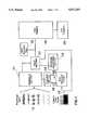
- FIG. 1is a block diagram of a multiplexer system illustrating the circuitry for simultaneous acquisition of video and electrophysiological input signals.
- FIG. 2is a schematic diagram of the multiplexer circuit configured for 16 input channels.
- FIG. 3Ais an illustration of a digitized video image mixed with 240 sampled physiological analog values.
- FIG. 3Billustrates six of the multiple reconstructed traces from FIG. 3A calculated by analytic routines from the digitized physiological data, sampled at 60 Hz.
- FIG. 4Ais a sample playback screen which shows the subject with eyes open. The subject was instructed to look right, causing a deflection in the EOG traces.
- FIG. 4Bis a sample playback screen which shows the subject with eyes closed. The subject was instructed to move his foot, causing the high frequency burst in the TIB EMG trace.
- FIG. 4Cillustrates a block diagram of the video and analog acquisition system used with the method as applied in the method of FIGS. 4A and 4B.
- FIG. 5illustrates a schematic diagram with a buffer system for use with the circuit.
- a system for processing multiple signalscomprises means for receiving a video signal representative of a camera image.
- the video signalis represented by pixels on horizontal lines.
- the analog signalsare representative of different analog inputs, and preferably physiological data.
- Meansis provided for mixing in a multiplexer the analog signals with the video signal.
- the analog signalsare contained on at least some of the horizontal lines of the video signal.
- Meansis provided for outputting the mixed integrated video signal and analog signals.
- the means for outputting the integrated signalis selectively at least one of a video digitizer onto which the video signal and analog signals have been integrated and mixed. Additionally or alternatively, the integrated signal can be stored on a video recorder, and/or tape, and/or stored on a host computer.
- the analog signalis represented by a vertical band as portion of the video image on a screen. Each line on the vertical band would be representative of a different analog signal. Where there are 240 horizontal lines representing the video image, there can be up to 240 analog signals. The intensity of the horizontal line on the portion of the band would be representative of the intensity of the analog signal. In this manner the analog signals are integrated into the video signal. Since the video signal is refreshed every 60 cycles per second, the analog signals are similarly refreshed every 60 cycles per second.
- the number of lines representative of the video signalis divided to repeat a selected number of analog signals for each video screen representation.
- a first predetermined number of linesnamely 240 would represent the video signal.
- a second predetermined number of signalsnamely 240 can represent 240 analog signals.
- a third number of linesbeing a lesser number than the second predetermined number can represent the analog signals.
- 120 analog signalscan be represented, each, twice in the 240 lines of the video signal.
- the analog signalsare inputted at twice the frequency of the video signal.
- Different multiplesnamely more, 4, 8 or 16 repetition times can be used, as necessary.
- the greater the frequency of repetitionthe fewer the number of analog signals available per video screen frame.
- a disadvantageis a 2 msec gap between fields which causes a timing error for reconstructing the analog signals with equal sample intervals.
- the diagram in FIG. 5illustrates signal buffering to solve timing errors.
- up to 8 physiological signals 10can be selected by a single analog-switch multiplexer 11, which is selected by two 4-bit binary counters 12. Up to 240 channels can be acquired with additional multiplexer circuits.
- Horizontal synchronizing signals (HS) 13 from the camera video input 14are used to increment the counters 12.
- the signal 13serves as a reference for the physiological data position circuit 15 to limit the portion of the horizontal line which is occupied by physiological data.
- Vertical synchronizing signals (VS) 16are used to reset the counters 12.
- a mixer 17is an analog-switch, which selects either video or physiological data.
- the output of the mixer 17is fed into the video digitizer 18, which samples video and physiological data simultaneously.
- the output of the mixer 17can be directed to a conventional video recorder 19.
- the video digitizerfeeds a host computer 20 for signal analysis as required.
- buffer amplifiers U1 through U4are used to isolate the physiological signals from circuit switching noise.
- Analog switches U5 and U6are 8 channel analog switches which select the physiological inputs in sequential order, based on the state of the counters U7 and U8.
- the countersare driven by the horizontal synchronizing pulses from sync-separator U11.
- Two decoders, U13 and U14,are used to select 1 of up to 30 multiplexer chips.
- the first two decoder outputsare not used, since the video digitizer or tape recorder may not process the first 16 horizonal lines which occur after the vertical synchronizing pulse.
- Each multiplexer chipcan select one of eight physiological inputs. Thus, a total of 240 inputs can be incorporated by using a total of thirty multiplexer circuits. Since the vertical synchronizing pulse resets the counter, each video field begins with physiological channel 0.
- the outputs of the multiplexersare selected for a short time by the X switch of the mixer which contains three independent switches: X, Y, and Z.
- the X switchis used for the sample-and-hold circuit
- the Y switchis used for the mixer
- the Z switchis not used.
- the X switchis closed, such that the selected physiological channel is sampled by the sample and hold circuit U15.
- the amplitude of the sample-and-hold outputcan be adjusted with VR1, and the offset adjusted with VR2.
- a re-triggerable one-shot U10is used to select the portion of the video screen occupied by the physiological channels. The left screen position is selected by VR3, and the duration of the displayed sample is selected by VR4.
- the one-shot U10waits a specified time, set by VR3, to turn on (physiological data selected) the Y switch of the mixer U9. This selects the output to be either camera video, or multiplexed physiological data.
- the second half of the one-shot U10waits a specified time, set by VR4, until switch Y is turned off, and the video data is selected.
- the systemconsists of several components.
- the first componentdetects horizontal synchronizing pulses from the input video signal of an NTSC (National Telecommunications Standards Committee) camera used to acquire images.
- the horizontal synchronizing pulsesincrement an eight-bit counter that sequentially selects each of 240 electrophysiological input analog signal channels to a sample-and-hold multiplexer.
- the output of the multiplexers U5 and U6represents a portion of each horizontal line composed of the sampled value from each electrophysiological channel.
- the multiplexer outputis mixed with the video signal.
- the intensity of a portion of each horizontal scan linerepresents the amplitude value of one physiological signal.
- the remainder of the scan linecontains video information. Typically, only a small portion of the video scan line is used to represent the physiological data.
- the mixed signalis then fed to a conventional video recorder for storage or to the input of a video digitizer 18. This simultaneously digitizes the physiological and video data as a 256 (8 bit) grey level signal.
- An LM1881 (National Semiconductor, Santa Clara, Calif.) sync-separator U11detects vertical synchronizing pulses (VS) and horizontal synchronizing pulses (HS) from the camera video input signal.
- the horizontal synchronizing pulsesare connected to the clock input of two four-bit counters U7 and U8.
- the falling edge of the horizontal synchronizing pulseselects one of the electrophysiological input signals through two or more multiplexer switches U5 and U6.
- Two sixteen-channel decoders U13 and U14are used to select the appropriate multiplexer chips U5, U6.
- the vertical synchronizing pulsesreset the counters U7 and U8 so that the count begins on the same channel for each field of the video signal.
- the outputs of the multiplexersare sampled by a switch U9. These outputs are amplified for adjustment of offset and gain of the physiological signals, and mixed to select either video or physiological data to be placed on the horizontal line.
- a one-shot circuit U10is driven by the horizontal synchronizing pulses to select the time window in which each physiological signal occupies the horizontal line.
- the digitizer board(Rambrandt, Progressive Peripherals, Denver, Colo.) incorporates a TMS34020 video processing chip (Texas Instruments Inc., Dallas, Tex.) that allows simultaneous acquisition and processing of 24 bit RGB or NTSC video.
- TMS34020 video processing chipTexas Instruments Inc., Dallas, Tex.
- data on the video portion of the lineare transferred to a host computer (A3000, Commodore Business Machines, West Chester, Pa.) together with one pixel from each horizontal line of the physiological data.
- a wide range of laboratory computerscould be used with an appropriate framegrabbing board capable of 8 bits or greater signal digitizing resolution.
- An Intel 80486 based computer33 MHz or 66 MHz clock rate with a high throughput framegrabber (ComputerEyes/RT; Digital Vision Inc., Dedham, Mass.) is effective to achieve equivalent results.
- the 486 based processorsrequire a fast-caching hard-disk controller to reduce processor time used for storage device access.
- one of the analog input channelsis connected to ground. Once a ground reference signal is acquired, the output from other channels is adjusted for DC shifts by a summing amplifier. For digitized data, the output of the physiological channels are offset by the digitized value of the ground reference channel.
- the physiological signalsare low-pass filtered at 30 Hz before the multiplexer to prevent aliasing. This facilitates monitoring slow-changing or relatively static conditions at the same time as monitoring fast-changing signals. For example, slow changes in temperature or light can be monitored as the ECG signals change.
- the IFFPHYS format(Interleaved File Format, Physical Data), a variation of the IFF format (Interleaved File Format, Electronic Arts, San Mateo, Calif.) is used for images, sound, and text storage. Details of the IFFPHYS is disclosed in D. Sirag, IFFPHYS: Interleaved File Formata, Physical Data, by David Sirag of 7215 So Harvest Avenue, Cerritos, Calif. 90701 and obtainable from Internet Number HARPER@AUNIX.LONI.UCLA.EDU, the contents of which are incorporated by reference herein.
- An analytic routineprovides retrieval of selected image frames by frame number and provides basic image analysis processes, such as averaging, image subtraction, and statistical processing of selected or all pixels in an image.
- FIG. 3AA sample multiplexed image is shown in FIG. 3A.
- the analog dataappear as short lines 30 towards the left portion of the field in FIG. 3A indicated by the arrow 31.
- the position of the sampled valuescan be placed anywhere in the video field 32.
- the intensity of each line 30represents the amplitude of the corresponding physiological channel.
- the width of the band or strip 33can be varied as required.
- the system and circuitryare used for simultaneous acquisition of up to 240 channels of electrophysiological data with video signals.
- the interleaved signalsare saved on conventional videotape recorders and retrieved through a de-multiplexing circuit or digitized at a later time.
- the analog-to-digital conversion resolution of typical video framegrabbersis 8 bits (one part in 256), which is comparable to the signal resolution obtained on FM-based instrumentation recorders. These recorders provide 44-48 Db signal to noise ratio. Within a 2 V signal range, the digitizer resolution is better than 10 My, an accuracy adequate for most physiological signals. The resolution requires care in monitoring the dynamic range of data to prevent distortion from coarse sampling resolution, or from exceeding the digitizer input range. A compounding amplifier may be used to convert the signals to log values to improve dynamic range but reduces resolution.
- a restrictionis the sampling rate. This is limited by the 60 Hz field refresh rate of the video signal. This restriction results from the limitation of storing only one sequence of 240 samples per field, namely one channel per line, to ensure equi-spaced samples of the electrophysiological inputs.
- the restriction in sample rateis removed with buffering of the incoming physiological signals, as illustrated in FIG. 5.
- the multiplexer circuitincreases the temporal resolution of mixed analog and video signals over the multiplexer of FIG. 2.
- the circuit of FIG. 2placed one value from each input channel on the image. This limited the sampling resolution to 60 Hz for each channel. 60 Hz is the combined repetition rate of the two video fields.
- 60 Hzis the combined repetition rate of the two video fields.
- Up to 256 channels of input 40are selected by a multiplexer 41 and converted to a 12-bit digital word by an analog-to-digital converter 42.
- the multiplexer 41is controlled by a counter and timing circuit 43 which is driven at a specific rate determined by a phase-locked-loop circuit 44, which is locked to the vertical sync of the video signal 45.
- This master clockis an integral multiple of the vertical refresh rate of the video signal 46.
- the timing circuit 43also gates the tristate data buffers 146 and address buffers 47 which store the digitized words into a memory block 48.
- the memory 48is divided into two buffers. While one buffer is being filled by the analog-to-digital converter, the second is read out by the output circuit. This implies that the analog data will always be offset in time by one video field.
- the vertical and horizontal sync signals 49 and 50also drive the output timing circuit 51 which reads out the buffer which has just been filed by the analog-to-digital circuit 42. Since the data are stored in digital form in memory 48, the values can be read at a faster rate than they were captured. This allows the digital-to-analog converter 52, the capability to represent each digitized value in any configuration on the output image.
- each horizontal linerepresents a particular channel. Pixels on the same line can represent each channel at a different point in time.
- the number of channels and sampling rateis limited only by the number of pixels which are available on the video image, and by the speed of the analog to digital converter.
- the datacan be encoded onto the video signal in at least two fashions.
- One processencodes the digital value of the analog signal as a proportionate intensity of the video signal. Each sample would be represented as a single pixel. This procedure is limited by signal-to-noise characteristics of standard video recorders, which for commercial units is approximately 46 db (approximately 7 bits of resolution). Recorders based on S-VHS principles have slightly better characteristics, with approximately 8 bits of resolution.
- Another encoding processis to encode each bit as a single "on” or “off” pixel (i.e., full black or full white level). By this means, little degradation of the signal occurs when encoding the digital value of the analog signal onto the video signal.
- a 12 bit samplefor example, would be represented as a string of 12 pixels, each of which would be "on” or "off”. Signal reconstruction is greatly enhanced because the resolution is not limited by the video digitizer.
- the bufferingadds to the complexity of the circuit.
- a 60 Hz sampling rateis sufficient for a variety of physiological signals, including respiratory signals, integrated electromyograph signals, movement signals, and EEG signals where the principal focus is activity below 30 Hz.
- the benefit of this systemincludes a large channel capacity for low bandwidth signals stored simultaneously with video at low cost.
- the recording time and digital storage capacity requiredis a function of image size and any compression performed on the video frame.
- the compressionshould be lossless to preserve the integrity of the physiological signals.
- the physiological signalscould be extracted before compression.
- the image sizeshould be sufficiently large to acquire the number of lines required for the physiological inputs; for example, at least 240 lines are needed for 240 physiological channels.
- the simplest imagescontain 256 grey levels from a monochrome camera. A color video is possible, but requires 24 bit RGB storage or 12 bit YUV encoding per digitized pixel to preserve the physiological data.
- FIGS. 4A and 4Bthere are two sample playback screens. Tick marks under the physiological traces of FIGS. 4A and 4B indicate 500 ms intervals (A).
- RESPRespiratory activity via chest wall expansion
- EEGElectroencephalogram
- TIB EMGTibialis Electromyogram.
- Each playback screen of FIGS. 4A and 4Bis drawn with 800 by 640 resolution.
- Each electrophysiological signalis plotted with a maximal 16 pixel amplitude. To achieve higher vertical discrimination of the analog traces, fewer channels could be displayed, leaving more pixels per channel.
- the hardware components used for the example illustrated in FIGS. 4A and 4Bare outlined in FIG. 4C.
- the video digitizer 60samples and compresses the images 61 and 62 from the video signal 63, and sends the data to the host computer 64 over the system bus 65.
- the analog digitizer 66samples the electrophysiological signals 67, 68 which are fed through lines 69 to the digitizer 66.
- the analog signalsare digitized and the data is transmitted over the parallel port 70.
- the host computer 64interleaves the two signals, and stores the digital information as a single file on a mass storage device 71.
- the procedureincorporated a microprocessor-based analog acquisition subsystem, a video framegrabber/processor board, a laboratory computer which served as host for the video board, and a large-capacity mass storage device.
- the framegrabber portion of the video boardwas an NTSC (National Telecommunications Standards Committee) device, capable of realtime digitizing at 60 fields/sec (Progressive Peripherals and Software, Denver, Colo.).
- the boardcontained a TI34020 processor (Texas Instruments Inc., Dallas, Tex.), math co-processor, 8 megabytes video ram, and 4 megabytes dynamic ram. A large number of comparable off-the-shelf boards are available.
- the boardwas used with an A3000 personal computer equipped with a Motorola 68030 or 68040 processor (Motorola Semiconductor Products Inc., Phoenix, Ariz.), modest amounts (2-4 megabyte) of memory, and a large mass storage device, typically a 2.5 gigabyte 8 mm helical scan tape.
- An analog-to-digital convertercurrently comprised of input amplifiers and a Motorola 68HC11 processor, was used for analog acquisition, and for data transfer to the host computer over a parallel interface.
- the video signalwas acquired with 8-bit (256 levels) grey scale resolution at a maximum 60 fields/sec by the framegrabber.
- a monochrome camerawas used for video which restricts the images to grey scale images.
- the signal definitionwas adequate for most observations, particularly at low light levels.
- the video processing boardis capable of high speed compression using the JPEG (Joint Photographic Engineering Group) algorithm, which reduces the image by a factor of 20 or more.
- the JPEG algorithmcan be constant or variable, and can be adjusted to alter compression over a wide range of factors, with increasing image quality loss at high degrees of compression. Compression is necessary for conditions of limited storage space and large image size requirements at high acquisition rates (greater than 3 fields/sec).
- the compression rateis determined by the acceptable level of image smoothing before identifying features of the image are lost. In some studies, such as imaging of subtle light scattering changes over time, only lossless compression is acceptable. Experiments which require only gross image assessment allow high compression rates; typically, image quality is compromised with compression factors greater than 50. Compression factors under 20 are usually indistinguishable from videotaped storage.
- the maximal acquisition rateis determined by many factors including pixel resolution, compression rate, computer processor speed, and average disk write speed. Typically, a 160 ⁇ 100 pixel resolution image is digitized at 3 fields/sec (48,000 bytes/sec) without compression, and is sufficient for distinguishing motor events such as large limb movements. Adequate reconstruction of the video field for identification of body movements can be achieved by this resolution, which reduces the throughput to the mass storage device considerably over higher resolution images. On a 2.5 gigabyte tape drive (capable of transfer rates of 250,000 bytes/sec), this acquisition rate provides storage for 41,667 sec (11.6 hr) of data.
- Up to 8 analog signalsare multiplexed and digitized under the control of a Motorola 68HC11 processor.
- An algorithmdeveloped under the FORTH programming language, stores the digitized values in one of two 8 kilobyte buffers and transfers full buffers over a parallel port to the host computer.
- Other devicesallow for 16 or 32 channels of analog data. Acquisition rates are up to 3000 samples/sec/channel.
- the intermixed video and analog dataare then transmitted through the bus of the host, plotted on the computer screen for real-time display, and stored on the mass storage device simultaneously in an interleaved format as a single file.
- the host computeralso outputs an incrementing binary-coded time code at 10 sec intervals through one digital-to-analog channel (normally used for audio output on the host computer) to synchronize polygraph or other recordings.
- An analytic programretrieves the physiological data and stores the data in IFFPHYS (Interleaved File Format, Physical Data; D. Sirag) format for analysis by a large number of previously developed routines.
- the IFFPHYS formatis based on the EA IFF (Electronic Arts, Interleaved File Format) standard developed for interchange of data, including graphics, sound and text material, between different computer systems (Electronic Arts, San Jose, Calif.).
- the IFFPHYS specificationprovides for text comments, includes a description of byte orientation (i.e., orientation of most significant bit), and stores file placement indications of analog, event, and video data for analytic routines.
- a single fileconsists of alternating blocks of video and electrophysiological data together with other notations.
- the analytic routines of the acquisition software and hardwareallow real-time display of the video images above the electrophysiological data in a polygraph format, and allow transfer to other analytic routines for spectral, cross-correlation and other calculations. Since the video and analog data are stored together in one file, examination of the relationship of physiological characteristics to video signals is facilitated. Thus, a compressed display showing median heart rate across an 11 hr recording might indicate, for example, an anomaly 4 hours into the record. The corresponding video acquired at that time is displayed immediately.
- FIGS. 3, 4A and 4BTwo screen displays from a single image 4.5 sec period of 8 physiological input channels acquired with this procedure are shown in FIGS. 3, 4A and 4B.
- the procedureacquires 8 channels of electrophysiological data, together with video images for prolonged periods of time.
- image acquisitioncan be reduced to rates appropriate for the study.
- acquisition at 3 to 15 fields/secis frequently used for some infant studies where only body position is of concern.
- higher acquisition ratescan be used to obtain smoother transitions between movements during review.
- An acquisition rateis necessary to achieve appropriate assessment of changes in the image.
- An advantage of the procedureis storage of video and analog data in a standard file format, the IFFPHYS format.
- This formatallows for storage of analog data with or without accompanying video, and provides a uniform format for analytic routines.
- considerable storage spacecan be saved by reducing the capture rate of the video signal.
- substantial reductions in image acquisitioncan be tolerated.
- Reduced image acquisition ratesobviously limit the temporal resolution for defining behavioral events.
- the procedureallows rapid access to video images, and easy examination of associated physiological data with observed events. Simultaneous acquisition and data interleaving obviates the need to synchronize computer-acquired physiological data with video data stored on tape, and the considerable operator costs involved in such observational data correlation.
- the procedureallows a degree of temporal synchronization (1/60 sec) which is difficult to achieve in conventional videotape acquisition without costly frame-accurate video recorders.
- the limitation of 8-bit resolution for the physiological signalscan be easily overcome by compounding with a logarithmic amplifier to achieve extended dynamic range.
- the 8 bit (1 part in 256) resolutionis comparable to the dynamic range of commercial instrumentation recorders, and judicious gain and offset settings will ensure adequate signal resolution.
- the combined video-analog acquisition featuresprovide substantial advantages when determination of the subject's behavior is of concern, or when correlation of physiological activity with behavior must be performed.
- the systemis of particular value when effective acquisition of video and physiological signals is necessary.
- the systemobviates a need for a separate analog-to-digital converter circuit for computer data acquisition, since such a converter is provided in the video framegrabber.
- a substantial benefitis the capability to store video and physiological signals simultaneously. This provides for rapid computer access to the interleaved data, without a need to align digitized information from separate sources. If computer storage is not required, the signals can be saved on videotape for later digitization.
- the system described hereis ideal for monitoring of infant sleep states and physiology in studies related to SIDS, for long-term monitoring of epileptic patients where both motor events and electrophysiological activity are of interest, and for studies of optical properties of tissue, where simultaneous video and electrophysiological signals are obtained.
- the vertical band of the analog signalis represented in FIG. 3A as being towards the left-hand side of the video image, it is possible to move this vertical band to different positions of the video screen as required.
- the thickness of the bandcan be varied as desired. The narrower the band, the better is the video image.
- the bandmay be represented by only a portion of the height of the video image. In such situations, the band can be located in a selected portion of the video screen as necessary.
- the representation of the analog signalscan be chosen for location on the video screen as desired.
- Any NTSC video digitizing board with the capacity for real time image acquisitioncan accomplish effective acquisition and processing of the video and analog signals.
- PAL video formatscan also be used with a consequent reduction in temporal resolution to 50 samples per second.
- the display of the analog datacan be confined to half or less than the full height of the video screen.
- a slower refresh rateis required, there would be fewer inputs of analog data, since the 240 inputs would be used repetitively.
- each of the 240 data lineswould be used twice, and the refresh would be twice as fast, namely 120 cycles/sec. This can be changed by various multiples as required.
- the inventionhas been described largely with regard to psychological data, there are clearly other applications. For instance, in scientific microscopy where video and analog data are obtained, the system will have useful advantages. Further, the video camera can be set up for microscopic viewing of tissues or events in a living or inanimate body.
Landscapes
- Engineering & Computer Science (AREA)
- Multimedia (AREA)
- Signal Processing (AREA)
- Health & Medical Sciences (AREA)
- Biomedical Technology (AREA)
- General Health & Medical Sciences (AREA)
- General Business, Economics & Management (AREA)
- Epidemiology (AREA)
- Business, Economics & Management (AREA)
- Medical Informatics (AREA)
- Primary Health Care (AREA)
- Public Health (AREA)
- Measuring And Recording Apparatus For Diagnosis (AREA)
- Closed-Circuit Television Systems (AREA)
- Television Signal Processing For Recording (AREA)
- Television Systems (AREA)
Abstract
Description
Claims (35)
Priority Applications (7)
| Application Number | Priority Date | Filing Date | Title |
|---|---|---|---|
| US08/234,300US5517251A (en) | 1994-04-28 | 1994-04-28 | Acquisition of video images simultaneously with analog signals |
| AU22975/95AAU693192B2 (en) | 1994-04-28 | 1995-04-25 | Acquisition of video images simultaneously with analog signals |
| EP95916489AEP0757874A4 (en) | 1994-04-28 | 1995-04-25 | SIMULTANEOUS ACQUISITION OF VIDEO IMAGES AND ANALOG SIGNALS |
| PCT/US1995/005073WO1995030304A1 (en) | 1994-04-28 | 1995-04-25 | Acquisition of video images simultaneously with analog signals |
| JP7528333AJPH10504144A (en) | 1994-04-28 | 1995-04-25 | Simultaneous capture of video image and analog signal |
| CA002187905ACA2187905A1 (en) | 1994-04-28 | 1995-04-25 | Acquisition of video images simultaneously with analog signals |
| US08/607,236US5798798A (en) | 1994-04-28 | 1996-02-26 | Simultaneously acquiring video images and analog signals |
Applications Claiming Priority (1)
| Application Number | Priority Date | Filing Date | Title |
|---|---|---|---|
| US08/234,300US5517251A (en) | 1994-04-28 | 1994-04-28 | Acquisition of video images simultaneously with analog signals |
Related Child Applications (1)
| Application Number | Title | Priority Date | Filing Date |
|---|---|---|---|
| US08/607,236Continuation-In-PartUS5798798A (en) | 1994-04-28 | 1996-02-26 | Simultaneously acquiring video images and analog signals |
Publications (1)
| Publication Number | Publication Date |
|---|---|
| US5517251Atrue US5517251A (en) | 1996-05-14 |
Family
ID=22880794
Family Applications (2)
| Application Number | Title | Priority Date | Filing Date |
|---|---|---|---|
| US08/234,300Expired - LifetimeUS5517251A (en) | 1994-04-28 | 1994-04-28 | Acquisition of video images simultaneously with analog signals |
| US08/607,236Expired - LifetimeUS5798798A (en) | 1994-04-28 | 1996-02-26 | Simultaneously acquiring video images and analog signals |
Family Applications After (1)
| Application Number | Title | Priority Date | Filing Date |
|---|---|---|---|
| US08/607,236Expired - LifetimeUS5798798A (en) | 1994-04-28 | 1996-02-26 | Simultaneously acquiring video images and analog signals |
Country Status (6)
| Country | Link |
|---|---|
| US (2) | US5517251A (en) |
| EP (1) | EP0757874A4 (en) |
| JP (1) | JPH10504144A (en) |
| AU (1) | AU693192B2 (en) |
| CA (1) | CA2187905A1 (en) |
| WO (1) | WO1995030304A1 (en) |
Cited By (22)
| Publication number | Priority date | Publication date | Assignee | Title |
|---|---|---|---|---|
| WO1997026823A1 (en)* | 1996-01-23 | 1997-07-31 | University Of Kansas | Systems for prediction, rapid detection, warning, prevention or control of changes in activity states in the brain |
| US5680176A (en)* | 1995-06-28 | 1997-10-21 | Daewoo Electronics, Co., Ltd. | Apparatus for controlling caption display on a wide aspect ratio |
| WO1997046972A1 (en)* | 1996-06-04 | 1997-12-11 | The Regents Of The University Of California | Video data representation of physiological data |
| US20040187167A1 (en)* | 1996-09-16 | 2004-09-23 | Discoverwhy Inc. | Data correlation and analysis tool |
| US20040183517A1 (en)* | 2003-03-17 | 2004-09-23 | Reilly James P. | Generation and measurement of timing delays by digital phase error compensation |
| US20050053262A1 (en)* | 2003-07-22 | 2005-03-10 | Joseph Szuba | Method of monitoring sleeping infant |
| US20050197590A1 (en)* | 1997-01-06 | 2005-09-08 | Ivan Osorio | System for the prediction, rapid detection, warning, prevention, or control of changes in activity states in the brain of a subject |
| US20050213442A1 (en)* | 2003-01-21 | 2005-09-29 | Sony Corporation | Data recording medium, recording method and recorder, reproducing method and reproducer, and data transmitting method and transmitter |
| US20060050930A1 (en)* | 2003-07-22 | 2006-03-09 | Ranjo Company | Method of monitoring sleeping infant |
| US20060140098A1 (en)* | 2004-12-29 | 2006-06-29 | Champion Mark A | Recording audio broadcast program |
| US20070270659A1 (en)* | 2006-05-03 | 2007-11-22 | Giegerich Gary D | Apparatus and Method for Remotely Detecting Deception |
| US20100070550A1 (en)* | 2008-09-12 | 2010-03-18 | Cardinal Health 209 Inc. | Method and apparatus of a sensor amplifier configured for use in medical applications |
| US20160246936A1 (en)* | 2011-02-16 | 2016-08-25 | Justin Kahn | Systems and methods for network-based counseling |
| US9704266B2 (en) | 2014-12-11 | 2017-07-11 | Rdi, Llc | Non-contacting monitor for bridges and civil structures |
| US10062411B2 (en) | 2014-12-11 | 2018-08-28 | Jeffrey R. Hay | Apparatus and method for visualizing periodic motions in mechanical components |
| CN109445347A (en)* | 2018-11-16 | 2019-03-08 | 美钻深海能源科技研发(上海)有限公司 | A kind of digital display unit and its display methods of collection in worksite signal |
| CN112826493A (en)* | 2020-12-29 | 2021-05-25 | 深圳市联影高端医疗装备创新研究院 | Physiological signal storage method, device, equipment and medium in medical imaging equipment |
| US11282213B1 (en) | 2020-06-24 | 2022-03-22 | Rdi Technologies, Inc. | Enhanced analysis techniques using composite frequency spectrum data |
| US11322182B1 (en) | 2020-09-28 | 2022-05-03 | Rdi Technologies, Inc. | Enhanced visualization techniques using reconstructed time waveforms |
| US11373317B1 (en) | 2020-01-24 | 2022-06-28 | Rdi Technologies, Inc. | Measuring the speed of rotation or reciprocation of a mechanical component using one or more cameras |
| US11423551B1 (en) | 2018-10-17 | 2022-08-23 | Rdi Technologies, Inc. | Enhanced presentation methods for visualizing motion of physical structures and machinery |
| US12300273B2 (en) | 2014-12-11 | 2025-05-13 | Rdi Technologies, Inc. | Apparatus and method for visualizing periodic motions in mechanical components |
Families Citing this family (99)
| Publication number | Priority date | Publication date | Assignee | Title |
|---|---|---|---|---|
| FR2786683B1 (en)* | 1998-12-02 | 2001-03-30 | Iodp | METHOD AND DEVICE FOR SYNCHRONOUS RECORDING OF ELECTROCARDIOGRAMS AND VIDEO IMAGES |
| US6415188B1 (en)* | 1998-12-23 | 2002-07-02 | Dennis Sunga Fernandez | Method and apparatus for multi-sensor processing |
| SE522856C2 (en)* | 1999-01-29 | 2004-03-09 | Axis Ab | A data storage and reduction method for digital images, as well as a monitoring system using said method |
| JP3519996B2 (en)* | 1999-08-05 | 2004-04-19 | 三洋電機株式会社 | Digital recording equipment |
| US6476858B1 (en) | 1999-08-12 | 2002-11-05 | Innovation Institute | Video monitoring and security system |
| US7310111B2 (en)* | 1999-08-12 | 2007-12-18 | Innovation Institute | Video monitoring and security system |
| US6724419B1 (en)* | 1999-08-13 | 2004-04-20 | Universal Imaging Corporation | System and method for acquiring images at maximum acquisition rate while asynchronously sequencing microscope devices |
| EP1210822A4 (en)* | 1999-08-13 | 2004-07-28 | Universal Imaging Corp | System and method for acquiring images at maximum acquisition rate while asynchronously sequencing microscope devices |
| AU779045B2 (en)* | 1999-10-12 | 2005-01-06 | Government of the United States of America, as Represented by the Secretary, Department of Health and Human Services, Centers for Disease Control and Prevention, The | Image-synchronized multichannel biomedical data acquisition system |
| US7392309B2 (en) | 1999-10-27 | 2008-06-24 | American Power Conversion Corporation | Network appliance management |
| US7330886B2 (en)* | 1999-10-27 | 2008-02-12 | American Power Conversion Corporation | Network appliance management |
| US6714977B1 (en) | 1999-10-27 | 2004-03-30 | Netbotz, Inc. | Method and system for monitoring computer networks and equipment |
| US6421080B1 (en)* | 1999-11-05 | 2002-07-16 | Image Vault Llc | Digital surveillance system with pre-event recording |
| IL136080A0 (en) | 2000-05-11 | 2001-05-20 | Yeda Res & Dev | Sequence-to-sequence alignment |
| US7002617B1 (en)* | 2000-07-20 | 2006-02-21 | Robert Samuel Smith | Coordinated audio and visual omnidirectional recording |
| EP1356431A2 (en)* | 2000-12-05 | 2003-10-29 | YEDA RESEARCH AND DEVELOPMENT Co. LTD. | Apparatus and method for alignment of spatial or temporal non-overlapping image sequences |
| EP1360796B1 (en)* | 2001-01-26 | 2009-12-23 | American Power Conversion Corporation | Method and system for a set of network appliances which can be connected to provide enhanced collaboration, scalability, and reliability |
| US8271626B2 (en) | 2001-01-26 | 2012-09-18 | American Power Conversion Corporation | Methods for displaying physical network topology and environmental status by location, organization, or responsible party |
| WO2002082999A1 (en)* | 2001-04-10 | 2002-10-24 | Battelle Memorial Institute | Image analysis system and method for discriminating movements of an individual |
| CA2446853A1 (en) | 2001-05-15 | 2002-11-21 | Psychogenics Inc. | Systems and methods for monitoring behavior informatics |
| US7428019B2 (en)* | 2001-12-26 | 2008-09-23 | Yeda Research And Development Co. Ltd. | System and method for increasing space or time resolution in video |
| WO2003094031A1 (en)* | 2002-05-03 | 2003-11-13 | Netbotz, Inc. | Method and apparatus for collecting and displaying network device information |
| JP4164644B2 (en)* | 2002-07-22 | 2008-10-15 | 株式会社日立メディコ | X-ray diagnostic imaging equipment |
| WO2004090679A2 (en) | 2003-04-14 | 2004-10-21 | Netbotz, Inc. | Environmental monitoring device |
| US8566292B2 (en) | 2003-04-14 | 2013-10-22 | Schneider Electric It Corporation | Method and system for journaling and accessing sensor and configuration data |
| US7542963B2 (en) | 2003-04-14 | 2009-06-02 | American Power Conversion Corporation | Method and system for journaling and accessing sensor and configuration data |
| DE602004024296D1 (en) | 2003-04-14 | 2010-01-07 | American Power Conv Corp | EXPANDABLE SENSOR MONITORING, WARNING PROCESSING AND NOTIFICATION SYSTEM AND METHOD |
| US7627651B2 (en)* | 2003-10-27 | 2009-12-01 | American Power Conversion Corporation | System and method for network device communication |
| US7477285B1 (en) | 2003-12-12 | 2009-01-13 | Careview Communication, Inc. | Non-intrusive data transmission network for use in an enterprise facility and method for implementing |
| US9311540B2 (en) | 2003-12-12 | 2016-04-12 | Careview Communications, Inc. | System and method for predicting patient falls |
| US8675059B2 (en) | 2010-07-29 | 2014-03-18 | Careview Communications, Inc. | System and method for using a video monitoring system to prevent and manage decubitus ulcers in patients |
| US9318012B2 (en) | 2003-12-12 | 2016-04-19 | Steve Gail Johnson | Noise correcting patient fall risk state system and method for predicting patient falls |
| US8145748B2 (en) | 2004-12-13 | 2012-03-27 | American Power Conversion Corporation | Remote monitoring system |
| US7711814B1 (en) | 2004-12-13 | 2010-05-04 | American Power Conversion Corporation | Method and system for remote monitoring of a power supply device with user registration capability |
| JP2006192105A (en) | 2005-01-14 | 2006-07-27 | Nippon Koden Corp | Biological information display system |
| FR2898482B1 (en)* | 2006-03-15 | 2008-06-13 | Hospices Civils De Lyon Etabli | METHOD FOR MONITORING A PATIENT AND SYSTEM FOR CARRYING OUT SAID METHOD. |
| US20080143831A1 (en)* | 2006-12-15 | 2008-06-19 | Daniel David Bowen | Systems and methods for user notification in a multi-use environment |
| US20080249376A1 (en)* | 2007-04-09 | 2008-10-09 | Siemens Medical Solutions Usa, Inc. | Distributed Patient Monitoring System |
| US20090138313A1 (en) | 2007-05-15 | 2009-05-28 | American Power Conversion Corporation | Methods and systems for managing facility power and cooling |
| US8382667B2 (en)* | 2010-10-01 | 2013-02-26 | Flint Hills Scientific, Llc | Detecting, quantifying, and/or classifying seizures using multimodal data |
| US9794523B2 (en) | 2011-12-19 | 2017-10-17 | Careview Communications, Inc. | Electronic patient sitter management system and method for implementing |
| US10645346B2 (en) | 2013-01-18 | 2020-05-05 | Careview Communications, Inc. | Patient video monitoring systems and methods having detection algorithm recovery from changes in illumination |
| US9866797B2 (en) | 2012-09-28 | 2018-01-09 | Careview Communications, Inc. | System and method for monitoring a fall state of a patient while minimizing false alarms |
| US9579047B2 (en) | 2013-03-15 | 2017-02-28 | Careview Communications, Inc. | Systems and methods for dynamically identifying a patient support surface and patient monitoring |
| US9959471B2 (en) | 2008-05-06 | 2018-05-01 | Careview Communications, Inc. | Patient video monitoring systems and methods for thermal detection of liquids |
| CA2666010A1 (en)* | 2008-05-14 | 2009-11-14 | The Hospital For Sick Children | Methods based on fluctuations in cortical synchronization |
| US8471899B2 (en)* | 2008-12-02 | 2013-06-25 | Careview Communications, Inc. | System and method for documenting patient procedures |
| US8990536B2 (en) | 2011-06-01 | 2015-03-24 | Schneider Electric It Corporation | Systems and methods for journaling and executing device control instructions |
| US20130127620A1 (en) | 2011-06-20 | 2013-05-23 | Cerner Innovation, Inc. | Management of patient fall risk |
| US9489820B1 (en) | 2011-07-12 | 2016-11-08 | Cerner Innovation, Inc. | Method for determining whether an individual leaves a prescribed virtual perimeter |
| US9741227B1 (en) | 2011-07-12 | 2017-08-22 | Cerner Innovation, Inc. | Method and process for determining whether an individual suffers a fall requiring assistance |
| US10546481B2 (en) | 2011-07-12 | 2020-01-28 | Cerner Innovation, Inc. | Method for determining whether an individual leaves a prescribed virtual perimeter |
| CN104137105B (en) | 2011-12-22 | 2017-07-11 | 施耐德电气It公司 | Analysis of the Effect of Transient Events on Temperature in Data Centers |
| US10096223B1 (en) | 2013-12-18 | 2018-10-09 | Cerner Innovication, Inc. | Method and process for determining whether an individual suffers a fall requiring assistance |
| US10225522B1 (en) | 2014-01-17 | 2019-03-05 | Cerner Innovation, Inc. | Method and system for determining whether an individual takes appropriate measures to prevent the spread of healthcare-associated infections |
| US10078956B1 (en) | 2014-01-17 | 2018-09-18 | Cerner Innovation, Inc. | Method and system for determining whether an individual takes appropriate measures to prevent the spread of healthcare-associated infections |
| US9729833B1 (en) | 2014-01-17 | 2017-08-08 | Cerner Innovation, Inc. | Method and system for determining whether an individual takes appropriate measures to prevent the spread of healthcare-associated infections along with centralized monitoring |
| US10438692B2 (en) | 2014-03-20 | 2019-10-08 | Cerner Innovation, Inc. | Privacy protection based on device presence |
| US9575560B2 (en) | 2014-06-03 | 2017-02-21 | Google Inc. | Radar-based gesture-recognition through a wearable device |
| US9921660B2 (en) | 2014-08-07 | 2018-03-20 | Google Llc | Radar-based gesture recognition |
| US9811164B2 (en) | 2014-08-07 | 2017-11-07 | Google Inc. | Radar-based gesture sensing and data transmission |
| US9588625B2 (en) | 2014-08-15 | 2017-03-07 | Google Inc. | Interactive textiles |
| US10268321B2 (en) | 2014-08-15 | 2019-04-23 | Google Llc | Interactive textiles within hard objects |
| US9778749B2 (en) | 2014-08-22 | 2017-10-03 | Google Inc. | Occluded gesture recognition |
| US11169988B2 (en) | 2014-08-22 | 2021-11-09 | Google Llc | Radar recognition-aided search |
| US9600080B2 (en) | 2014-10-02 | 2017-03-21 | Google Inc. | Non-line-of-sight radar-based gesture recognition |
| WO2016092503A1 (en)* | 2014-12-10 | 2016-06-16 | Sparkbio S.R.L. | System for the capture and combined display of video and analog signals coming from electromedical instruments and equipment |
| US10090068B2 (en) | 2014-12-23 | 2018-10-02 | Cerner Innovation, Inc. | Method and system for determining whether a monitored individual's hand(s) have entered a virtual safety zone |
| US10524722B2 (en) | 2014-12-26 | 2020-01-07 | Cerner Innovation, Inc. | Method and system for determining whether a caregiver takes appropriate measures to prevent patient bedsores |
| US10064582B2 (en) | 2015-01-19 | 2018-09-04 | Google Llc | Noninvasive determination of cardiac health and other functional states and trends for human physiological systems |
| US11275757B2 (en) | 2015-02-13 | 2022-03-15 | Cerner Innovation, Inc. | Systems and methods for capturing data, creating billable information and outputting billable information |
| US10091463B1 (en) | 2015-02-16 | 2018-10-02 | Cerner Innovation, Inc. | Method for determining whether an individual enters a prescribed virtual zone using 3D blob detection |
| US10016162B1 (en) | 2015-03-23 | 2018-07-10 | Google Llc | In-ear health monitoring |
| US9983747B2 (en) | 2015-03-26 | 2018-05-29 | Google Llc | Two-layer interactive textiles |
| US10433793B1 (en)* | 2015-03-27 | 2019-10-08 | Cadwell Laboratories, Inc. | Methods and systems for simultaneous review of brain activity and physical manifestations of users |
| US9848780B1 (en) | 2015-04-08 | 2017-12-26 | Google Inc. | Assessing cardiovascular function using an optical sensor |
| US10438215B2 (en)* | 2015-04-10 | 2019-10-08 | International Business Machines Corporation | System for observing and analyzing customer opinion |
| EP3289434A1 (en) | 2015-04-30 | 2018-03-07 | Google LLC | Wide-field radar-based gesture recognition |
| KR102236958B1 (en) | 2015-04-30 | 2021-04-05 | 구글 엘엘씨 | Rf-based micro-motion tracking for gesture tracking and recognition |
| KR102327044B1 (en) | 2015-04-30 | 2021-11-15 | 구글 엘엘씨 | Type-agnostic rf signal representations |
| US10342478B2 (en) | 2015-05-07 | 2019-07-09 | Cerner Innovation, Inc. | Method and system for determining whether a caretaker takes appropriate measures to prevent patient bedsores |
| US10080528B2 (en) | 2015-05-19 | 2018-09-25 | Google Llc | Optical central venous pressure measurement |
| US10088908B1 (en) | 2015-05-27 | 2018-10-02 | Google Llc | Gesture detection and interactions |
| US9693592B2 (en) | 2015-05-27 | 2017-07-04 | Google Inc. | Attaching electronic components to interactive textiles |
| US9892611B1 (en) | 2015-06-01 | 2018-02-13 | Cerner Innovation, Inc. | Method for determining whether an individual enters a prescribed virtual zone using skeletal tracking and 3D blob detection |
| US10376195B1 (en) | 2015-06-04 | 2019-08-13 | Google Llc | Automated nursing assessment |
| US10817065B1 (en) | 2015-10-06 | 2020-10-27 | Google Llc | Gesture recognition using multiple antenna |
| CN107851932A (en) | 2015-11-04 | 2018-03-27 | 谷歌有限责任公司 | Connectors for connecting electronics embedded in clothing to external devices |
| US10614288B2 (en) | 2015-12-31 | 2020-04-07 | Cerner Innovation, Inc. | Methods and systems for detecting stroke symptoms |
| WO2017192167A1 (en) | 2016-05-03 | 2017-11-09 | Google Llc | Connecting an electronic component to an interactive textile |
| WO2017200570A1 (en) | 2016-05-16 | 2017-11-23 | Google Llc | Interactive object with multiple electronics modules |
| WO2017198894A1 (en)* | 2016-05-20 | 2017-11-23 | Nokia Technologies Oy | Method and apparatus for matching vital sign information to a concurrently recorded data set |
| US10579150B2 (en) | 2016-12-05 | 2020-03-03 | Google Llc | Concurrent detection of absolute distance and relative movement for sensing action gestures |
| US10147184B2 (en) | 2016-12-30 | 2018-12-04 | Cerner Innovation, Inc. | Seizure detection |
| US10643446B2 (en) | 2017-12-28 | 2020-05-05 | Cerner Innovation, Inc. | Utilizing artificial intelligence to detect objects or patient safety events in a patient room |
| US10482321B2 (en) | 2017-12-29 | 2019-11-19 | Cerner Innovation, Inc. | Methods and systems for identifying the crossing of a virtual barrier |
| US10922936B2 (en) | 2018-11-06 | 2021-02-16 | Cerner Innovation, Inc. | Methods and systems for detecting prohibited objects |
| CN110545403B (en)* | 2019-08-23 | 2021-06-18 | 和宇健康科技股份有限公司 | Operating room visual data transmission method, device, medium and terminal equipment |
| US12148512B2 (en) | 2019-12-31 | 2024-11-19 | Cerner Innovation, Inc. | Patient safety using virtual observation |
Citations (10)
| Publication number | Priority date | Publication date | Assignee | Title |
|---|---|---|---|---|
| US3798366A (en)* | 1972-03-06 | 1974-03-19 | R Winkler | Infrared imaging system |
| US3993861A (en)* | 1975-03-24 | 1976-11-23 | Sanders Associates, Inc. | Digital video modulation and demodulation system |
| US4018986A (en)* | 1974-07-30 | 1977-04-19 | Siemens Aktiengesellschaft | Circuit arrangement for the transmission and presentation of an analog signal with a video signal |
| US4051522A (en)* | 1975-05-05 | 1977-09-27 | Jonathan Systems | Patient monitoring system |
| US4186413A (en)* | 1977-11-14 | 1980-01-29 | Sanders Associates, Inc. | Apparatus for receiving encoded messages on the screen of a television receiver and for redisplay thereof on the same receiver screen in a readable format |
| US4218707A (en)* | 1977-05-13 | 1980-08-19 | Her Majesty The Queen In Right Of Canada, As Represented By The Minister Of National Defence | Thermographic areameter |
| US4807031A (en)* | 1987-10-20 | 1989-02-21 | Interactive Systems, Incorporated | Interactive video method and apparatus |
| US4855827A (en)* | 1987-07-21 | 1989-08-08 | Worlds Of Wonder, Inc. | Method of providing identification, other digital data and multiple audio tracks in video systems |
| US4876600A (en)* | 1987-01-26 | 1989-10-24 | Ibp Pietzsch Gmbh | Method and device for representing a composite image on a screen of a screen device |
| US4969041A (en)* | 1988-09-23 | 1990-11-06 | Dubner Computer Systems, Inc. | Embedment of data in a video signal |
Family Cites Families (6)
| Publication number | Priority date | Publication date | Assignee | Title |
|---|---|---|---|---|
| US4045815A (en)* | 1976-02-04 | 1977-08-30 | The United States Of America As Represented By The Secretary Of The Department Of Health, Education And Welfare | System for combining analog and image signals into a standard video format |
| US5010328A (en)* | 1987-07-21 | 1991-04-23 | Thorn Emi Plc | Display device |
| US5321750A (en)* | 1989-02-07 | 1994-06-14 | Market Data Corporation | Restricted information distribution system apparatus and methods |
| US5594467A (en)* | 1989-12-06 | 1997-01-14 | Video Logic Ltd. | Computer based display system allowing mixing and windowing of graphics and video |
| US5611038A (en)* | 1991-04-17 | 1997-03-11 | Shaw; Venson M. | Audio/video transceiver provided with a device for reconfiguration of incompatibly received or transmitted video and audio information |
| US5331417A (en)* | 1992-09-15 | 1994-07-19 | Digital Pictures, Inc. | System and method of displaying a plurality of digital video images |
- 1994
- 1994-04-28USUS08/234,300patent/US5517251A/ennot_activeExpired - Lifetime
- 1995
- 1995-04-25WOPCT/US1995/005073patent/WO1995030304A1/ennot_activeApplication Discontinuation
- 1995-04-25EPEP95916489Apatent/EP0757874A4/ennot_activeCeased
- 1995-04-25AUAU22975/95Apatent/AU693192B2/ennot_activeCeased
- 1995-04-25CACA002187905Apatent/CA2187905A1/ennot_activeAbandoned
- 1995-04-25JPJP7528333Apatent/JPH10504144A/enactivePending
- 1996
- 1996-02-26USUS08/607,236patent/US5798798A/ennot_activeExpired - Lifetime
Patent Citations (10)
| Publication number | Priority date | Publication date | Assignee | Title |
|---|---|---|---|---|
| US3798366A (en)* | 1972-03-06 | 1974-03-19 | R Winkler | Infrared imaging system |
| US4018986A (en)* | 1974-07-30 | 1977-04-19 | Siemens Aktiengesellschaft | Circuit arrangement for the transmission and presentation of an analog signal with a video signal |
| US3993861A (en)* | 1975-03-24 | 1976-11-23 | Sanders Associates, Inc. | Digital video modulation and demodulation system |
| US4051522A (en)* | 1975-05-05 | 1977-09-27 | Jonathan Systems | Patient monitoring system |
| US4218707A (en)* | 1977-05-13 | 1980-08-19 | Her Majesty The Queen In Right Of Canada, As Represented By The Minister Of National Defence | Thermographic areameter |
| US4186413A (en)* | 1977-11-14 | 1980-01-29 | Sanders Associates, Inc. | Apparatus for receiving encoded messages on the screen of a television receiver and for redisplay thereof on the same receiver screen in a readable format |
| US4876600A (en)* | 1987-01-26 | 1989-10-24 | Ibp Pietzsch Gmbh | Method and device for representing a composite image on a screen of a screen device |
| US4855827A (en)* | 1987-07-21 | 1989-08-08 | Worlds Of Wonder, Inc. | Method of providing identification, other digital data and multiple audio tracks in video systems |
| US4807031A (en)* | 1987-10-20 | 1989-02-21 | Interactive Systems, Incorporated | Interactive video method and apparatus |
| US4969041A (en)* | 1988-09-23 | 1990-11-06 | Dubner Computer Systems, Inc. | Embedment of data in a video signal |
Non-Patent Citations (2)
| Title |
|---|
| David J. Sirag, IFF Phys Routines for IFF physical data files, 1989.* |
| David J. Sirag, IFF Phys--Routines for IFF physical data files, 1989. |
Cited By (45)
| Publication number | Priority date | Publication date | Assignee | Title |
|---|---|---|---|---|
| US5680176A (en)* | 1995-06-28 | 1997-10-21 | Daewoo Electronics, Co., Ltd. | Apparatus for controlling caption display on a wide aspect ratio |
| WO1997026823A1 (en)* | 1996-01-23 | 1997-07-31 | University Of Kansas | Systems for prediction, rapid detection, warning, prevention or control of changes in activity states in the brain |
| US6549804B1 (en) | 1996-01-23 | 2003-04-15 | University Of Kansas | System for the prediction, rapid detection, warning, prevention or control of changes in activity states in the brain of a subject |
| WO1997046972A1 (en)* | 1996-06-04 | 1997-12-11 | The Regents Of The University Of California | Video data representation of physiological data |
| US6001060A (en)* | 1996-06-04 | 1999-12-14 | Regents Of The University Of California | Video data representation of physiological data |
| US20040187167A1 (en)* | 1996-09-16 | 2004-09-23 | Discoverwhy Inc. | Data correlation and analysis tool |
| US20050197590A1 (en)* | 1997-01-06 | 2005-09-08 | Ivan Osorio | System for the prediction, rapid detection, warning, prevention, or control of changes in activity states in the brain of a subject |
| US7630757B2 (en) | 1997-01-06 | 2009-12-08 | Flint Hills Scientific Llc | System for the prediction, rapid detection, warning, prevention, or control of changes in activity states in the brain of a subject |
| US20100194995A1 (en)* | 2003-01-21 | 2010-08-05 | Sony Corporation | Data recording medium, data recording method, data recording apparatus, data reproducing method, data reproducing apparatus, data transmitting method, and data transmitting apparatus |
| US20050213442A1 (en)* | 2003-01-21 | 2005-09-29 | Sony Corporation | Data recording medium, recording method and recorder, reproducing method and reproducer, and data transmitting method and transmitter |
| US6956422B2 (en)* | 2003-03-17 | 2005-10-18 | Indiana University Research And Technology Corporation | Generation and measurement of timing delays by digital phase error compensation |
| US20040183517A1 (en)* | 2003-03-17 | 2004-09-23 | Reilly James P. | Generation and measurement of timing delays by digital phase error compensation |
| US20050053262A1 (en)* | 2003-07-22 | 2005-03-10 | Joseph Szuba | Method of monitoring sleeping infant |
| US20060050930A1 (en)* | 2003-07-22 | 2006-03-09 | Ranjo Company | Method of monitoring sleeping infant |
| US7035432B2 (en)* | 2003-07-22 | 2006-04-25 | Ronjo Company | Method of monitoring sleeping infant |
| US20060140098A1 (en)* | 2004-12-29 | 2006-06-29 | Champion Mark A | Recording audio broadcast program |
| US20070270659A1 (en)* | 2006-05-03 | 2007-11-22 | Giegerich Gary D | Apparatus and Method for Remotely Detecting Deception |
| US20100070550A1 (en)* | 2008-09-12 | 2010-03-18 | Cardinal Health 209 Inc. | Method and apparatus of a sensor amplifier configured for use in medical applications |
| US20160246936A1 (en)* | 2011-02-16 | 2016-08-25 | Justin Kahn | Systems and methods for network-based counseling |
| US11482326B2 (en)* | 2011-02-16 | 2022-10-25 | Teladog Health, Inc. | Systems and methods for network-based counseling |
| US12224059B2 (en) | 2011-02-16 | 2025-02-11 | Teladoc Health, Inc. | Systems and methods for network-based counseling |
| US10712924B2 (en) | 2014-12-11 | 2020-07-14 | Rdi Technologies, Inc. | Non-contacting monitor for bridges and civil structures |
| US12300273B2 (en) | 2014-12-11 | 2025-05-13 | Rdi Technologies, Inc. | Apparatus and method for visualizing periodic motions in mechanical components |
| US10459615B2 (en) | 2014-12-11 | 2019-10-29 | Rdi Technologies, Inc. | Apparatus and method for analyzing periodic motions in machinery |
| US10521098B2 (en) | 2014-12-11 | 2019-12-31 | Rdi Technologies, Inc. | Non-contacting monitor for bridges and civil structures |
| US10643659B1 (en) | 2014-12-11 | 2020-05-05 | Rdi Technologies, Inc. | Apparatus and method for visualizing periodic motions in mechanical components |
| US10108325B2 (en) | 2014-12-11 | 2018-10-23 | Rdi Technologies, Inc. | Method of analyzing, displaying, organizing and responding to vital signals |
| US10877655B1 (en) | 2014-12-11 | 2020-12-29 | Rdi Technologies, Inc. | Method of analyzing, displaying, organizing and responding to vital signals |
| US10062411B2 (en) | 2014-12-11 | 2018-08-28 | Jeffrey R. Hay | Apparatus and method for visualizing periodic motions in mechanical components |
| US11275496B2 (en) | 2014-12-11 | 2022-03-15 | Rdi Technologies, Inc. | Non-contacting monitor for bridges and civil structures |
| US11803297B2 (en) | 2014-12-11 | 2023-10-31 | Rdi Technologies, Inc. | Non-contacting monitor for bridges and civil structures |
| US11631432B1 (en) | 2014-12-11 | 2023-04-18 | Rdi Technologies, Inc. | Apparatus and method for visualizing periodic motions in mechanical components |
| US11599256B1 (en) | 2014-12-11 | 2023-03-07 | Rdi Technologies, Inc. | Method of analyzing, displaying, organizing and responding to vital signals |
| US9704266B2 (en) | 2014-12-11 | 2017-07-11 | Rdi, Llc | Non-contacting monitor for bridges and civil structures |
| US11423551B1 (en) | 2018-10-17 | 2022-08-23 | Rdi Technologies, Inc. | Enhanced presentation methods for visualizing motion of physical structures and machinery |
| US12190532B1 (en) | 2018-10-17 | 2025-01-07 | Rdi Technologies, Inc. | Enhanced presentation methods for visualizing motion of physical structures and machinery |
| CN109445347A (en)* | 2018-11-16 | 2019-03-08 | 美钻深海能源科技研发(上海)有限公司 | A kind of digital display unit and its display methods of collection in worksite signal |
| US11557043B1 (en) | 2020-01-24 | 2023-01-17 | Rdi Technologies, Inc. | Measuring the Torsional Vibration of a mechanical component using one or more cameras |
| US11373317B1 (en) | 2020-01-24 | 2022-06-28 | Rdi Technologies, Inc. | Measuring the speed of rotation or reciprocation of a mechanical component using one or more cameras |
| US11816845B1 (en) | 2020-01-24 | 2023-11-14 | Rdi Technologies, Inc. | Measuring the speed of rotation or reciprocation of a mechanical component using one or more cameras |
| US11756212B1 (en) | 2020-06-24 | 2023-09-12 | Rdi Technologies, Inc. | Enhanced analysis techniques using composite frequency spectrum data |
| US11282213B1 (en) | 2020-06-24 | 2022-03-22 | Rdi Technologies, Inc. | Enhanced analysis techniques using composite frequency spectrum data |
| US11600303B1 (en) | 2020-09-28 | 2023-03-07 | Rdi Technologies, Inc. | Enhanced visualization techniques using reconstructed time waveforms |
| US11322182B1 (en) | 2020-09-28 | 2022-05-03 | Rdi Technologies, Inc. | Enhanced visualization techniques using reconstructed time waveforms |
| CN112826493A (en)* | 2020-12-29 | 2021-05-25 | 深圳市联影高端医疗装备创新研究院 | Physiological signal storage method, device, equipment and medium in medical imaging equipment |
Also Published As
| Publication number | Publication date |
|---|---|
| AU2297595A (en) | 1995-11-29 |
| CA2187905A1 (en) | 1995-11-09 |
| EP0757874A4 (en) | 1998-07-29 |
| WO1995030304A1 (en) | 1995-11-09 |
| AU693192B2 (en) | 1998-06-25 |
| JPH10504144A (en) | 1998-04-14 |
| US5798798A (en) | 1998-08-25 |
| EP0757874A1 (en) | 1997-02-12 |
Similar Documents
| Publication | Publication Date | Title |
|---|---|---|
| US5517251A (en) | Acquisition of video images simultaneously with analog signals | |
| Yen et al. | A video-based system for acquiring biomechanical data synchronized with arbitrary events and activities | |
| US4579125A (en) | Real-time EEG spectral analyzer | |
| US5762611A (en) | Evaluation of a subject's interest in education, training and other materials using brain activity patterns | |
| AU779045B2 (en) | Image-synchronized multichannel biomedical data acquisition system | |
| CA2051683A1 (en) | Cerebral biopotential analysis system and method | |
| US4045815A (en) | System for combining analog and image signals into a standard video format | |
| US3841309A (en) | Method of analyzing cerebral electrical activity | |
| US6104948A (en) | Method for visually integrating multiple data acquisition technologies for real time and retrospective analysis | |
| US20040034285A1 (en) | Body movement analysis system and body movement analysis method | |
| Rector et al. | A data acquisition system for long-term monitoring of physiological and video signals | |
| Burgess | Design and evolution of a system for long-term electroencephalographic and video monitoring of epilepsy patients | |
| Rector et al. | Low-cost acquisition of video images simultaneously with 240 electrophysiological signals | |
| Griffiths et al. | A video system for investigating breathing disorders during sleep. | |
| Harlaar et al. | The SYBAR system: integrated recording and display of video, EMG, and force plate data | |
| Zeng et al. | A new video-synchronized multichannel biomedical data acquisition system | |
| Jestico et al. | Automatic and rapid visual analysis of sleep stages and epileptic activity. A preliminary report | |
| Gorney | The practical guide to digital EEG | |
| van de Velde et al. | Digital archival and exchange of events in a simple format for polygraphic recordings with application in event related potential studies | |
| EP0215604A2 (en) | Video and analogue data recording system | |
| Radwin et al. | A Video-Based System for Acquiring Biomechanical Data Synchronized with Arbitrary Events and Activities | |
| Osselton | Electroencephalographic monitoring in epilepsy | |
| Gates et al. | Role and implementation of long-term monitoring for epilepsy | |
| Kamp et al. | Longterm monitoring of the electroencephalogram in epileptic patients | |
| Enison et al. | Graphical electrocardiogram waveforms as part of an integrated hospital system's patient record |
Legal Events
| Date | Code | Title | Description |
|---|---|---|---|
| AS | Assignment | Owner name:REGENTS OF THE UNIVERSITY OF CALIFORNIA, THE, CALI Free format text:ASSIGNMENT OF ASSIGNORS INTEREST;ASSIGNORS:RECTOR, DAVID M.;HARPER, RONALD M.;REEL/FRAME:006977/0278 Effective date:19940420 | |
| AS | Assignment | Owner name:NATIONAL INSTITUTES OF HEALTH, THE, MARYLAND Free format text:CONFIRMATORY LICENSE;ASSIGNOR:CALIFORNIA, THE REGENTS OF THE UNIVERSITY OF;REEL/FRAME:007895/0030 Effective date:19940815 | |
| STCF | Information on status: patent grant | Free format text:PATENTED CASE | |
| FEPP | Fee payment procedure | Free format text:PAT HLDR NO LONGER CLAIMS SMALL ENT STAT AS NONPROFIT ORG (ORIGINAL EVENT CODE: LSM3); ENTITY STATUS OF PATENT OWNER: LARGE ENTITY | |
| FEPP | Fee payment procedure | Free format text:PAYOR NUMBER ASSIGNED (ORIGINAL EVENT CODE: ASPN); ENTITY STATUS OF PATENT OWNER: LARGE ENTITY | |
| FPAY | Fee payment | Year of fee payment:4 | |
| REMI | Maintenance fee reminder mailed | ||
| REIN | Reinstatement after maintenance fee payment confirmed | ||
| FP | Lapsed due to failure to pay maintenance fee | Effective date:20040514 | |
| FEPP | Fee payment procedure | Free format text:PETITION RELATED TO MAINTENANCE FEES FILED (ORIGINAL EVENT CODE: PMFP); ENTITY STATUS OF PATENT OWNER: LARGE ENTITY | |
| FPAY | Fee payment | Year of fee payment:8 | |
| SULP | Surcharge for late payment | ||
| FEPP | Fee payment procedure | Free format text:PETITION RELATED TO MAINTENANCE FEES GRANTED (ORIGINAL EVENT CODE: PMFG); ENTITY STATUS OF PATENT OWNER: LARGE ENTITY | |
| PRDP | Patent reinstated due to the acceptance of a late maintenance fee | Effective date:20060918 | |
| PRDP | Patent reinstated due to the acceptance of a late maintenance fee | Effective date:20060918 | |
| FPAY | Fee payment | Year of fee payment:12 | |
| AS | Assignment | Owner name:NATIONAL INSTITUTES OF HEALTH (NIH), U.S. DEPT. OF Free format text:CONFIRMATORY LICENSE;ASSIGNOR:UNIVERSITY OF CALIFORNIA;REEL/FRAME:022018/0558 Effective date:19940815 |