US5517176A - Emergency exit bar with dual sensors - Google Patents
Emergency exit bar with dual sensorsDownload PDFInfo
- Publication number
- US5517176A US5517176AUS08/384,787US38478795AUS5517176AUS 5517176 AUS5517176 AUS 5517176AUS 38478795 AUS38478795 AUS 38478795AUS 5517176 AUS5517176 AUS 5517176A
- Authority
- US
- United States
- Prior art keywords
- exit bar
- generating
- bar
- time period
- alarm
- Prior art date
- Legal status (The legal status is an assumption and is not a legal conclusion. Google has not performed a legal analysis and makes no representation as to the accuracy of the status listed.)
- Expired - Fee Related
Links
- 230000009977dual effectEffects0.000titledescription2
- 230000008859changeEffects0.000claimsabstractdescription10
- 238000001514detection methodMethods0.000claimsdescription7
- 230000004044responseEffects0.000claimsdescription6
- 230000000712assemblyEffects0.000claimsdescription3
- 238000000429assemblyMethods0.000claimsdescription3
- 239000004020conductorSubstances0.000description3
- 230000035945sensitivityEffects0.000description3
- 230000004913activationEffects0.000description2
- 230000007257malfunctionEffects0.000description2
- 239000000463materialSubstances0.000description2
- 230000007246mechanismEffects0.000description2
- 230000006978adaptationEffects0.000description1
- XAGFODPZIPBFFR-UHFFFAOYSA-NaluminiumChemical compound[Al]XAGFODPZIPBFFR-UHFFFAOYSA-N0.000description1
- 229910052782aluminiumInorganic materials0.000description1
- 230000007797corrosionEffects0.000description1
- 238000005260corrosionMethods0.000description1
- 230000007812deficiencyEffects0.000description1
- 238000010586diagramMethods0.000description1
- 230000000694effectsEffects0.000description1
- 230000004048modificationEffects0.000description1
- 238000012986modificationMethods0.000description1
- 239000012811non-conductive materialSubstances0.000description1
- 230000011664signalingEffects0.000description1
- 230000001960triggered effectEffects0.000description1
Images


Classifications
- E—FIXED CONSTRUCTIONS
- E05—LOCKS; KEYS; WINDOW OR DOOR FITTINGS; SAFES
- E05B—LOCKS; ACCESSORIES THEREFOR; HANDCUFFS
- E05B65/00—Locks or fastenings for special use
- E05B65/10—Locks or fastenings for special use for panic or emergency doors
- E05B65/1046—Panic bars
- E—FIXED CONSTRUCTIONS
- E05—LOCKS; KEYS; WINDOW OR DOOR FITTINGS; SAFES
- E05B—LOCKS; ACCESSORIES THEREFOR; HANDCUFFS
- E05B65/00—Locks or fastenings for special use
- E05B65/10—Locks or fastenings for special use for panic or emergency doors
- E05B65/108—Electronically controlled emergency exits
- E—FIXED CONSTRUCTIONS
- E05—LOCKS; KEYS; WINDOW OR DOOR FITTINGS; SAFES
- E05B—LOCKS; ACCESSORIES THEREFOR; HANDCUFFS
- E05B45/00—Alarm locks
- E05B45/06—Electric alarm locks
- E—FIXED CONSTRUCTIONS
- E05—LOCKS; KEYS; WINDOW OR DOOR FITTINGS; SAFES
- E05C—BOLTS OR FASTENING DEVICES FOR WINGS, SPECIALLY FOR DOORS OR WINDOWS
- E05C19/00—Other devices specially designed for securing wings, e.g. with suction cups
- E05C19/16—Devices holding the wing by magnetic or electromagnetic attraction
- E05C19/166—Devices holding the wing by magnetic or electromagnetic attraction electromagnetic
- Y—GENERAL TAGGING OF NEW TECHNOLOGICAL DEVELOPMENTS; GENERAL TAGGING OF CROSS-SECTIONAL TECHNOLOGIES SPANNING OVER SEVERAL SECTIONS OF THE IPC; TECHNICAL SUBJECTS COVERED BY FORMER USPC CROSS-REFERENCE ART COLLECTIONS [XRACs] AND DIGESTS
- Y10—TECHNICAL SUBJECTS COVERED BY FORMER USPC
- Y10T—TECHNICAL SUBJECTS COVERED BY FORMER US CLASSIFICATION
- Y10T292/00—Closure fasteners
- Y10T292/08—Bolts
- Y10T292/0908—Emergency operating means
- Y—GENERAL TAGGING OF NEW TECHNOLOGICAL DEVELOPMENTS; GENERAL TAGGING OF CROSS-SECTIONAL TECHNOLOGIES SPANNING OVER SEVERAL SECTIONS OF THE IPC; TECHNICAL SUBJECTS COVERED BY FORMER USPC CROSS-REFERENCE ART COLLECTIONS [XRACs] AND DIGESTS
- Y10—TECHNICAL SUBJECTS COVERED BY FORMER USPC
- Y10T—TECHNICAL SUBJECTS COVERED BY FORMER US CLASSIFICATION
- Y10T70/00—Locks
- Y10T70/50—Special application
- Y10T70/5093—For closures
- Y10T70/5155—Door
- Y10T70/5159—Emergency exit
Definitions
- This inventionrelates to the field of door security systems. More specifically, this invention relates to the use of exit or panic bars for the emergency egress through a doorway.
- Exit bars which allow egress through a doorway during normal and emergency situationsare well known in the art of door security systems.
- Conventional exit barstypically employ a mechanical movement to operate a latch mechanism. This mechanical movement which triggers unlocking of a door results from a force exerted on the exit bar by a person attempting to egress through the doorway.
- exit bars for such locksare responsive to a contact force on the exit bar to actuate an electrical switch which causes the lock to release.
- Mechanical exit bars, whether directly operating latches or actuating switches to operate electrical lockstypically have the same problems.
- a mechanical exit baris subject to wear of the components and to the possibility of becoming jammed. An exit bar jammed in a permanent unlocked state is a risk to security by allowing unauthorized entrance from the outside. An exit bar jammed in a permanent locked state can have catastrophic safety consequences.
- Capacitance sensitive barsAs a response to some of the deficiencies of mechanical exit bars, bars which are sensitive to capacitance changes for controlling the operation of electromagnetic locks have been employed. Capacitance sensitive bars, however, can fail if the sensitivity of the electronics is improperly adjusted or changes during operation. In addition, insufficient capacitance change may not be a reliable indicator of a person wanting to egress under all circumstances, for example, when the bar is contacted by an insulated material such as a glove or a coat.
- the inventionin a preferred form is an electronic emergency exit bar for the actuation of an electromechanical or electromagnetic lock.
- the exit barmaintains the general appearance of a traditional mechanical exit bar so as to assure users of its function.
- the exit bar of the inventionincorporates two redundant sensor systems to determine when a person is attempting an egress through a secured door.
- the first sensor systememploys an infrared beam traversing along the front face of the exit bar.
- An infrared emitteris located at one end of the exit bar and an infrared sensor is positioned at the opposite end of the bar to receive the infrared beam from the emitter. Any object interrupting the infrared beam triggers the sensor system thereby sending a signal to the lock operator to release the electromechanical or electromagnetic lock.
- the second sensor systememploys a capacitance change sensor.
- the exit bar of the inventionis constructed of an electrically conductive material. Conductively connected to the exit bar is a sensor which detects changes in the capacitance. When a person comes into contact or close proximity with the exit bar, the capacitance of a capacitance circuit will increase and trigger the sensor to send a signal to the lock operator to release an electromechanical or electromagnetic lock.
- An exit bar of the preferred embodiment of the inventionenhances security and reliability because of the utilization of two independent sensor systems. Contact or near contact on the front of the bar results in at least one sensor system signaling the lock operator to release the lock.
- FIG. 1is a longitudinal sectional view, partly broken away, of an emergency exit bar of the invention.
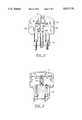
- FIG. 2is an interior cross-sectional view of the emergency exit bar of FIG. 1 taken along the line A--A thereof.
- FIG. 3is an interior cross-sectional view of the emergency exit bar of FIG. 1 taken along the line B--B thereof.
- FIG. 4is an enlarged fragmentary view, partly broken away and partly in phantom, of the emergency exit bar of FIG. 1 taken along the line C--C thereof.
- FIG. 5is a front view, partly in schematic, of the emergency exit bar of FIG. 1 with an associated door, doorway and lock system;
- FIG. 6is a schematic block diagram of the electronics of the exit bar of FIG. 5.
- an emergency exit bar of the inventionis generally represented by the numeral 10.
- the exit bar 10is mounted to exit door 14 (FIG. 5).
- the exit bar 10operates to sense an individual attempting to exit through door 14 and effect a release of a lock such as electromagnetic lock 46.
- the exit bar 10comprises a tubular main body 12 which has a D-shaped cross section and is of sufficient length to extend across substantially the entire width of the door 14.
- the main body 12is manufactured from electrically conductive material but may be finished or coated with a non--conductive material.
- the main body 12is preferably formed from aluminum and anodized to resist corrosion.
- the electrically conductive body 12is mounted to the door 14 by means of insulated mounting blocks 16 positioned at opposite end locations of the body 12. The blocks 16 are required to be insulated when the bar is mounted on a conductive door for proper capacitance sensor function.
- the body 12is affixed to the mounting blocks by screws 18.
- Each end cap assemblycomprises an infra-red emitter or sensor support 22 and an end plate 24.
- a screw 26extends through the end plate 24, through holes 28 in the sensor support, and into a central support groove 30 cast into the length of the body 12.
- a printed circuit board 32spans the width and partial length of the body 12 to act as a mounting panel for some of the circuitry and components 33 (illustrated schematically in FIG. 1) as will be described below.
- the circuit board 32is affixed to the sensor support 22 by means of a screw 34 threaded into the sensor support 22. Additionally, circuit board 32 is affixed to the back of the body 12 by means of internal support block 36.
- a screw 38is threaded into one end of the conducting block 36 and a screw 40 is countersunk into the back of the body 12 and threaded into the opposite end of each internal support block 36.
- a signal cable passage 42 for the signal cable 44extends through one of the mounting blocks 16.
- signal cable 44carries signals from the emergency exit bar 10 which are supplied by relays 64 and 65 (FIG. 6).
- the relayswhen activated by the sensor systems release an electromagnetic lock.
- the lock controllercontrols the operation of the associated electromagnetic lock 46 or other locking mechanism (not illustrated).
- the lock 46is responsive through the relays 64, 65 to a capacitance sensor unit and an independent redundant infrared sensor unit located at the emergency exit bar 10.
- a capacitance sensor unit and an independent redundant infrared sensor unitlocated at the emergency exit bar 10.
- all the electronics including relays 64, 65 of the exit bar sensorsare located on circuit board 32.
- the signal cable 44brings power to the exit bar circuits and carries signals from the relays to the lock controller 62.
- a capacitance sensing circuit 60detects changes in the capacitance of the emergency exit bar 10.
- the body 12 and end cap portions 20are all constructed of a conductive material.
- the capacitance sensing circuitemploys an oscillator 63 to determine changes in the capacitance of the cavity defined by the tubular body 12 of the bar 10. When a person wishing to exit through the doorway on which the emergency exit bar 10 is in close proximity or touches the emergency exit bar 10, the capacitance of the bar will increase.
- the sensing circuit 60senses the changing capacitance and signals the lock controller 62 through the relay 64.
- a flip flop circuit or switchchanges state so that a signal is applied to the single pole, double throw relay 64 which activates the lock 64 to allow egress through the doorway.
- the capacitance sensor 60has a sensitivity adjustment 61 which is adjustable to prevent releasing the lock for capacitance changes below a preset level.
- the second sensor systememploys an ultra high power infrared LED 48 located in one sensor support 22 (on the left in FIG. 1).
- a preferred model of a suitable infrared LEDis a Stanley DN305.
- the LEDemits an infrared beam 49 that travels the length of and parallel to the body 12 forwardly from the front face.
- the beam 49is received by a photo IC 50 located in the other sensor support 22.
- the photo IC 50is capable of detecting interruption of the beam under strong background light circumstances.
- Preferred photo ICs suitable for such conditionsare the Hamamatsu light modulation photo receiver of the S4282 series and the S4285 series.
- the photo emitter 48is connected to an infrared receiver circuit 66 by signal lines 51, 52.
- the photo receiver 50is also connected to the infrared receiver circuit 66 by means of signal lines 54, 55.
- a signalis applied to activate the relay 65.
- the relaysignals the lock 46 to release via cable 44. The beam interruption thus releases the electromagnetic lock 46 to allow egress through the doorway.
- the dual sensor systemsprovide a reliable redundant sensing function. Under normal circumstances, the capacitance sensing circuit will sense contact or near contact anywhere on the exposed surfaces of the emergency bar and release the electromagnetic lock 46. However, under some circumstances, should the bar be contacted by an insulated material, the capacitance of the bar may not significantly change and the lock may fail to release. The photo beam across the front of the body 12 will actuate the lock whenever the beam is interrupted by someone wishing to egress through the doorway. Should contact or near contact occur anywhere on the emergency exit bar to change the capacitance of the bar or the photo beam be interrupted, the two independent sensors combine to allow release of the doorway lock. It should be recognized that either sensor may independently signal the lock to release. Both sensors need not be simultaneously activated to effectuate a release of the lock 46.
- Signal cable 44is mounted to support plate 32 by means of an electrical connector 56. Signals are transmitted along the length of the bar 12 via a flexible internal electrical cable 58 to a second electrical connector 60 connected to the photo receiver 50 by line 54. Preferably, the maximum possible length between the two end portions can be accommodated by the cable 58. Therefore, an emergency exit bar of any suitable length can be constructed essentially by simply fixing the length of the body 12 without any other dimensional adjustments to wiring or other components.
- an alarm circuit 67(FIG. 6) is integrated into the exit bar circuitry. Continual activation of either sensor system results in the activation of an audible alarm 68.
- the sound characteristics of each alarmcan be specific to the sensor that is being activated.
- a beep of three signals per secondindicates the activated condition. Should the infrared photo beam be interrupted for more than 15 seconds, a faster beep cycle of six signals per second indicates the infrared system is activated.
- the alarm circuit 67by means of alarm 68 can identify and readily indicate to the appropriate personnel the malfunction.
- the alarm 68may also indicate that the background or sensitivity adjustments for the infrared sensor and the capacitance sensor are not properly adjusted.
- the alarm circuit 67can also be triggered by an auxiliary switch 70 to attract security personnel to the site of the doorway.
- All of the circuits of the exit barare preferably energized by means of an external power supply 72.
- the exit barmay also be configured to provide for either a fail-safe or fail-secure operating mode.
Landscapes
- Business, Economics & Management (AREA)
- Emergency Management (AREA)
- Burglar Alarm Systems (AREA)
Abstract
Description
Claims (20)
Priority Applications (1)
| Application Number | Priority Date | Filing Date | Title |
|---|---|---|---|
| US08/384,787US5517176A (en) | 1995-02-06 | 1995-02-06 | Emergency exit bar with dual sensors |
Applications Claiming Priority (1)
| Application Number | Priority Date | Filing Date | Title |
|---|---|---|---|
| US08/384,787US5517176A (en) | 1995-02-06 | 1995-02-06 | Emergency exit bar with dual sensors |
Publications (1)
| Publication Number | Publication Date |
|---|---|
| US5517176Atrue US5517176A (en) | 1996-05-14 |
Family
ID=23518765
Family Applications (1)
| Application Number | Title | Priority Date | Filing Date |
|---|---|---|---|
| US08/384,787Expired - Fee RelatedUS5517176A (en) | 1995-02-06 | 1995-02-06 | Emergency exit bar with dual sensors |
Country Status (1)
| Country | Link |
|---|---|
| US (1) | US5517176A (en) |
Cited By (18)
| Publication number | Priority date | Publication date | Assignee | Title |
|---|---|---|---|---|
| US6009732A (en)* | 1998-04-07 | 2000-01-04 | Detex Corporation | Panic exit device |
| US6091322A (en)* | 1999-09-15 | 2000-07-18 | Daimlerchrysler Corporation | Trunk monitoring system |
| US6104594A (en)* | 1999-03-10 | 2000-08-15 | Harrow Products, Inc. | Electromagnetic latch retractor for exit bar |
| US20030141455A1 (en)* | 2002-01-31 | 2003-07-31 | Lambert David K. | Integrated light concentrator |
| US20040177663A1 (en)* | 2003-03-11 | 2004-09-16 | Harrow Products, Inc. | Override assembly for door lock systems having a clutch mechanism |
| US20040196155A1 (en)* | 2003-04-03 | 2004-10-07 | Scott Wilker | Safety system |
| US20050237214A1 (en)* | 2004-04-07 | 2005-10-27 | Dynalock Corporation | Electromagnetic door security system |
| US20110067308A1 (en)* | 2009-09-20 | 2011-03-24 | Hunt Robert C | Access Control Device for a Door |
| US20120205920A1 (en)* | 2011-02-11 | 2012-08-16 | Chandler Partners International, Ltd. | Autonomous door defense system and method |
| US20130140831A1 (en)* | 2011-12-05 | 2013-06-06 | Audi Ag | Emergency release device for a vehicle trunk |
| US9105169B2 (en) | 2009-07-10 | 2015-08-11 | Jeffrey L. Hanning | Alarm system for passageways |
| EP2886967A3 (en)* | 2013-12-20 | 2015-10-21 | Schilling Engineering GmbH | Clean room device |
| US9305445B1 (en) | 2009-07-10 | 2016-04-05 | Jeffrey L. Hanning | Alarm system for passageways |
| US10060161B2 (en)* | 2016-10-19 | 2018-08-28 | I-Ting Shen | Inner operating device for a door lock |
| US10344502B2 (en) | 2016-02-04 | 2019-07-09 | Schlage Lock Company Llc | User sensing exit device |
| US10370872B2 (en) | 2017-02-24 | 2019-08-06 | Schlage Lock Company Llc | Exit device systems and methods |
| US10948591B2 (en) | 2018-05-18 | 2021-03-16 | Michael Louis Spardel | Exit obstruction warning system |
| US20240312274A1 (en)* | 2020-03-27 | 2024-09-19 | Home Valet, Inc. | Apparatus to allow for storage or holding of items, especially for deliveries and/or pickups |
Citations (7)
| Publication number | Priority date | Publication date | Assignee | Title |
|---|---|---|---|---|
| US4006471A (en)* | 1975-01-31 | 1977-02-01 | Detex Corporation | Emergency exit lock system for doors |
| US4763937A (en)* | 1986-09-11 | 1988-08-16 | Sittnick Jr Ralph A | Electromagnetic door lock system |
| US4804945A (en)* | 1987-10-29 | 1989-02-14 | Terrance Millet | Door alarm with infrared and capacitive sensors |
| US4831279A (en)* | 1986-09-29 | 1989-05-16 | Nartron Corporation | Capacity responsive control circuit |
| US4893852A (en)* | 1989-01-17 | 1990-01-16 | Harrow Products, Inc. | Dual sensor electromagnetic door lock system |
| US4961330A (en)* | 1989-09-12 | 1990-10-09 | Sargent & Greenleaf, Inc. | High security panic exit system |
| US5027552A (en)* | 1990-08-16 | 1991-07-02 | Miller Edge, Inc. | Redundant sensing edge for a door for detecting an object in proximity to the door edge |
- 1995
- 1995-02-06USUS08/384,787patent/US5517176A/ennot_activeExpired - Fee Related
Patent Citations (7)
| Publication number | Priority date | Publication date | Assignee | Title |
|---|---|---|---|---|
| US4006471A (en)* | 1975-01-31 | 1977-02-01 | Detex Corporation | Emergency exit lock system for doors |
| US4763937A (en)* | 1986-09-11 | 1988-08-16 | Sittnick Jr Ralph A | Electromagnetic door lock system |
| US4831279A (en)* | 1986-09-29 | 1989-05-16 | Nartron Corporation | Capacity responsive control circuit |
| US4804945A (en)* | 1987-10-29 | 1989-02-14 | Terrance Millet | Door alarm with infrared and capacitive sensors |
| US4893852A (en)* | 1989-01-17 | 1990-01-16 | Harrow Products, Inc. | Dual sensor electromagnetic door lock system |
| US4961330A (en)* | 1989-09-12 | 1990-10-09 | Sargent & Greenleaf, Inc. | High security panic exit system |
| US5027552A (en)* | 1990-08-16 | 1991-07-02 | Miller Edge, Inc. | Redundant sensing edge for a door for detecting an object in proximity to the door edge |
Cited By (31)
| Publication number | Priority date | Publication date | Assignee | Title |
|---|---|---|---|---|
| US6205825B1 (en) | 1998-04-07 | 2001-03-27 | Detex Corporation | Panic exit device mounting plate |
| US6532777B2 (en) | 1998-04-07 | 2003-03-18 | Detex Corporation | Panic exit device mounting plate |
| US6009732A (en)* | 1998-04-07 | 2000-01-04 | Detex Corporation | Panic exit device |
| US6104594A (en)* | 1999-03-10 | 2000-08-15 | Harrow Products, Inc. | Electromagnetic latch retractor for exit bar |
| US6091322A (en)* | 1999-09-15 | 2000-07-18 | Daimlerchrysler Corporation | Trunk monitoring system |
| US20050098729A1 (en)* | 2002-01-31 | 2005-05-12 | Delphi Technologies, Inc. | Integrated light concentrator |
| US20030141455A1 (en)* | 2002-01-31 | 2003-07-31 | Lambert David K. | Integrated light concentrator |
| US7096698B2 (en) | 2003-03-11 | 2006-08-29 | Harrow Products Llc | Override assembly for door lock systems having a clutch mechanism |
| US20040177663A1 (en)* | 2003-03-11 | 2004-09-16 | Harrow Products, Inc. | Override assembly for door lock systems having a clutch mechanism |
| US6859145B2 (en)* | 2003-04-03 | 2005-02-22 | Scott Wilker | Safety system |
| US20040196155A1 (en)* | 2003-04-03 | 2004-10-07 | Scott Wilker | Safety system |
| US20050237214A1 (en)* | 2004-04-07 | 2005-10-27 | Dynalock Corporation | Electromagnetic door security system |
| US7051560B2 (en)* | 2004-04-07 | 2006-05-30 | Dynalock Corporation | Electromagnetic door security system |
| US9305445B1 (en) | 2009-07-10 | 2016-04-05 | Jeffrey L. Hanning | Alarm system for passageways |
| US9105169B2 (en) | 2009-07-10 | 2015-08-11 | Jeffrey L. Hanning | Alarm system for passageways |
| US9151096B2 (en)* | 2009-09-20 | 2015-10-06 | Hanchett Entry Systems, Inc. | Access control device for a door |
| US20110067308A1 (en)* | 2009-09-20 | 2011-03-24 | Hunt Robert C | Access Control Device for a Door |
| US20120205920A1 (en)* | 2011-02-11 | 2012-08-16 | Chandler Partners International, Ltd. | Autonomous door defense system and method |
| US9284757B2 (en)* | 2011-12-05 | 2016-03-15 | Audi Ag | Emergency release device for a vehicle trunk |
| US20130140831A1 (en)* | 2011-12-05 | 2013-06-06 | Audi Ag | Emergency release device for a vehicle trunk |
| EP2886967A3 (en)* | 2013-12-20 | 2015-10-21 | Schilling Engineering GmbH | Clean room device |
| US10344502B2 (en) | 2016-02-04 | 2019-07-09 | Schlage Lock Company Llc | User sensing exit device |
| US11473342B2 (en) | 2016-02-04 | 2022-10-18 | Schlage Lock Company Llc | User sensing exit device |
| US10060161B2 (en)* | 2016-10-19 | 2018-08-28 | I-Ting Shen | Inner operating device for a door lock |
| US11459798B2 (en) | 2017-02-24 | 2022-10-04 | Schlage Lock Company Llc | Exit device systems and methods |
| US10968664B2 (en) | 2017-02-24 | 2021-04-06 | Schlage Lock Company Llc | Exit device systems and methods |
| US11255109B2 (en) | 2017-02-24 | 2022-02-22 | Schlage Lock Company Llc | Exit device systems and methods |
| US10370872B2 (en) | 2017-02-24 | 2019-08-06 | Schlage Lock Company Llc | Exit device systems and methods |
| US11891839B2 (en) | 2017-02-24 | 2024-02-06 | Schlage Lock Company Llc | Exit device systems and methods |
| US10948591B2 (en) | 2018-05-18 | 2021-03-16 | Michael Louis Spardel | Exit obstruction warning system |
| US20240312274A1 (en)* | 2020-03-27 | 2024-09-19 | Home Valet, Inc. | Apparatus to allow for storage or holding of items, especially for deliveries and/or pickups |
Similar Documents
| Publication | Publication Date | Title |
|---|---|---|
| US5517176A (en) | Emergency exit bar with dual sensors | |
| USRE35268E (en) | Door security system | |
| USRE46832E1 (en) | Electromagnetic lock having distance-sensing monitoring system | |
| US6609738B1 (en) | Electromagnetic door lock system | |
| US5479151A (en) | Electromagnetic door lock with on-board programmable access control | |
| US6963280B2 (en) | Door security device for use in security systems | |
| US5321963A (en) | Door locking system having a sensor for controlling activating/deactivating of a locking device | |
| US7355515B2 (en) | Magnetic security device for securing doors | |
| US7469942B2 (en) | Delayed egress exit device | |
| US4763937A (en) | Electromagnetic door lock system | |
| US4797657A (en) | Portable self-contained intrusion detector for passenger aircraft | |
| CA2629047C (en) | Exit alarm escutcheon | |
| US9151096B2 (en) | Access control device for a door | |
| US4893852A (en) | Dual sensor electromagnetic door lock system | |
| US20090090148A1 (en) | Lock sensor detection system | |
| US5496079A (en) | Swinging electromagnetic lock | |
| PT1977063E (en) | A device for controlling a door | |
| US4937560A (en) | Security system with door deadbolt interlock | |
| US5062670A (en) | Lock monitor | |
| US7051560B2 (en) | Electromagnetic door security system | |
| US5754107A (en) | Pressure actuated dead bolt premises intrusion alarm and intruder | |
| US5003290A (en) | Integrated alarm and access control system | |
| US6020816A (en) | Door and window lock with burglar alarm | |
| EP0537010A1 (en) | Door locking system | |
| GB2282634A (en) | Garage door intruder alarm |
Legal Events
| Date | Code | Title | Description |
|---|---|---|---|
| AS | Assignment | Owner name:HARROW PRODUCTS, INC. A CORPORATION OF DE Free format text:ASSIGNMENT OF ASSIGNORS INTEREST;ASSIGNORS:LAVELLE, GARY E.;FROLOV, GEORGE;BAEHR, GEORGE A.;REEL/FRAME:007413/0883 Effective date:19950203 | |
| FEPP | Fee payment procedure | Free format text:PAYOR NUMBER ASSIGNED (ORIGINAL EVENT CODE: ASPN); ENTITY STATUS OF PATENT OWNER: LARGE ENTITY | |
| FPAY | Fee payment | Year of fee payment:4 | |
| REMI | Maintenance fee reminder mailed | ||
| LAPS | Lapse for failure to pay maintenance fees | ||
| FP | Lapsed due to failure to pay maintenance fee | Effective date:20040514 | |
| AS | Assignment | Owner name:HARROW PRODUCTS LLC, NEW JERSEY Free format text:CHANGE OF NAME;ASSIGNOR:HARROW PRODUCTS, INC.;REEL/FRAME:030936/0421 Effective date:20031121 | |
| AS | Assignment | Owner name:SCHLAGE LOCK COMPANY LLC, INDIANA Free format text:ASSIGNMENT OF ASSIGNORS INTEREST;ASSIGNOR:HARROW PRODUCTS LLC;REEL/FRAME:030982/0812 Effective date:20130805 | |
| AS | Assignment | Owner name:HARROW PRODUCTS LLC, INDIANA Free format text:CORRECTIVE ASSIGNMENT TO CORRECT THE ASSIGNEE FROM SCHLAGE LOCK COMPANY LLC TO HARROW PRODUCTS LLC PREVIOUSLY RECORDED ON REEL 030982 FRAME 0812. ASSIGNOR(S) HEREBY CONFIRMS THE ASSIGNMENT;ASSIGNOR:HARROW PRODUCTS LLC;REEL/FRAME:031478/0690 Effective date:20130805 | |
| AS | Assignment | Owner name:JPMORGAN CHASE BANK, N.A., AS ADMINISTRATIVE AGENT Free format text:SECURITY AGREEMENT;ASSIGNOR:SCHLAGE LOCK COMPANY LLC;REEL/FRAME:031831/0091 Effective date:20131126 | |
| AS | Assignment | Owner name:JPMORGAN CHASE BANK, N.A., AS ADMINISTRATIVE AGENT Free format text:SECURITY AGREEMENT;ASSIGNOR:SCHLAGE LOCK COMPANY LLC;REEL/FRAME:034173/0001 Effective date:20141015 | |
| STCH | Information on status: patent discontinuation | Free format text:PATENT EXPIRED DUE TO NONPAYMENT OF MAINTENANCE FEES UNDER 37 CFR 1.362 |