US5515572A - Electronic vacuum cleaner control system - Google Patents
Electronic vacuum cleaner control systemDownload PDFInfo
- Publication number
- US5515572A US5515572AUS08/455,670US45567095AUS5515572AUS 5515572 AUS5515572 AUS 5515572AUS 45567095 AUS45567095 AUS 45567095AUS 5515572 AUS5515572 AUS 5515572A
- Authority
- US
- United States
- Prior art keywords
- vacuum cleaner
- hose
- control unit
- canister
- microcontroller
- Prior art date
- Legal status (The legal status is an assumption and is not a legal conclusion. Google has not performed a legal analysis and makes no representation as to the accuracy of the status listed.)
- Expired - Fee Related
Links
Images


Classifications
- A—HUMAN NECESSITIES
- A47—FURNITURE; DOMESTIC ARTICLES OR APPLIANCES; COFFEE MILLS; SPICE MILLS; SUCTION CLEANERS IN GENERAL
- A47L—DOMESTIC WASHING OR CLEANING; SUCTION CLEANERS IN GENERAL
- A47L9/00—Details or accessories of suction cleaners, e.g. mechanical means for controlling the suction or for effecting pulsating action; Storing devices specially adapted to suction cleaners or parts thereof; Carrying-vehicles specially adapted for suction cleaners
- A47L9/28—Installation of the electric equipment, e.g. adaptation or attachment to the suction cleaner; Controlling suction cleaners by electric means
- A47L9/2894—Details related to signal transmission in suction cleaners
- A—HUMAN NECESSITIES
- A47—FURNITURE; DOMESTIC ARTICLES OR APPLIANCES; COFFEE MILLS; SPICE MILLS; SUCTION CLEANERS IN GENERAL
- A47L—DOMESTIC WASHING OR CLEANING; SUCTION CLEANERS IN GENERAL
- A47L9/00—Details or accessories of suction cleaners, e.g. mechanical means for controlling the suction or for effecting pulsating action; Storing devices specially adapted to suction cleaners or parts thereof; Carrying-vehicles specially adapted for suction cleaners
- A47L9/28—Installation of the electric equipment, e.g. adaptation or attachment to the suction cleaner; Controlling suction cleaners by electric means
- A47L9/2805—Parameters or conditions being sensed
- A47L9/281—Parameters or conditions being sensed the amount or condition of incoming dirt or dust
- A—HUMAN NECESSITIES
- A47—FURNITURE; DOMESTIC ARTICLES OR APPLIANCES; COFFEE MILLS; SPICE MILLS; SUCTION CLEANERS IN GENERAL
- A47L—DOMESTIC WASHING OR CLEANING; SUCTION CLEANERS IN GENERAL
- A47L9/00—Details or accessories of suction cleaners, e.g. mechanical means for controlling the suction or for effecting pulsating action; Storing devices specially adapted to suction cleaners or parts thereof; Carrying-vehicles specially adapted for suction cleaners
- A47L9/28—Installation of the electric equipment, e.g. adaptation or attachment to the suction cleaner; Controlling suction cleaners by electric means
- A47L9/2836—Installation of the electric equipment, e.g. adaptation or attachment to the suction cleaner; Controlling suction cleaners by electric means characterised by the parts which are controlled
- A47L9/2842—Suction motors or blowers
- A—HUMAN NECESSITIES
- A47—FURNITURE; DOMESTIC ARTICLES OR APPLIANCES; COFFEE MILLS; SPICE MILLS; SUCTION CLEANERS IN GENERAL
- A47L—DOMESTIC WASHING OR CLEANING; SUCTION CLEANERS IN GENERAL
- A47L9/00—Details or accessories of suction cleaners, e.g. mechanical means for controlling the suction or for effecting pulsating action; Storing devices specially adapted to suction cleaners or parts thereof; Carrying-vehicles specially adapted for suction cleaners
- A47L9/28—Installation of the electric equipment, e.g. adaptation or attachment to the suction cleaner; Controlling suction cleaners by electric means
- A47L9/2857—User input or output elements for control, e.g. buttons, switches or displays
- Y—GENERAL TAGGING OF NEW TECHNOLOGICAL DEVELOPMENTS; GENERAL TAGGING OF CROSS-SECTIONAL TECHNOLOGIES SPANNING OVER SEVERAL SECTIONS OF THE IPC; TECHNICAL SUBJECTS COVERED BY FORMER USPC CROSS-REFERENCE ART COLLECTIONS [XRACs] AND DIGESTS
- Y02—TECHNOLOGIES OR APPLICATIONS FOR MITIGATION OR ADAPTATION AGAINST CLIMATE CHANGE
- Y02B—CLIMATE CHANGE MITIGATION TECHNOLOGIES RELATED TO BUILDINGS, e.g. HOUSING, HOUSE APPLIANCES OR RELATED END-USER APPLICATIONS
- Y02B40/00—Technologies aiming at improving the efficiency of home appliances, e.g. induction cooking or efficient technologies for refrigerators, freezers or dish washers
Definitions
- This inventionrelates to vacuum cleaners, and more particularly to electronic control systems for vacuum cleaners.
- Vacuum cleanersare typically provided with simple controls that allow the user to turn on and off the unit and perhaps to select the power to be applied to the suction motor to vary the level of suction.
- simple controlsthat allow the user to turn on and off the unit and perhaps to select the power to be applied to the suction motor to vary the level of suction.
- microcontrollersto direct the operation of the unit.
- the functions that have been addedhave not always been those desired by the user.
- the added functionality provided by the addition of electronic controlshas made vacuum cleaner control systems needlessly complex and overly expensive.
- canister vacuum cleanerstwo microcontrollers have sometimes been used to control the operation of the vacuum cleaner, one located in the canister and another in the handle that is connected to the vacuum cleaner hose and that contains the user controls.
- Other canister vacuum cleanershave supported various automatic modes of operation, but have either required that any optical dust sensor be located in the canister, which is cumbersome if the microcontroller used to control the operation of the vacuum cleaner is located in the handle, or have employed needlessly complex processing routines to determine the appropriate power setting of the suction motor.
- Still other vacuum cleanershave not allowed a user to easily select between a variety of bag change modes. While some previously known canister vacuum cleaners have had blow ports to which the vacuum cleaner hose could be attached, in has not been possible to control the operation of these vacuum cleaners using circuitry in a handle connected to the hose.
- a canister vacuum cleanerin which a microcontroller-based control unit contained in the handle of the vacuum cleaner is connected to the canister by a wired hose, which supports two-way communications between the control unit and the suction motor and various sensors contained in the canister, thereby allowing a single microcontroller to be used, simplifying the construction of the unit.
- a vacuum cleanerthat can be placed in one of two user-selectable bag change modes: a maximum suction bag change mode, in which the vacuum cleaner shuts off when the pressure drop across the vacuum cleaner bag exceeds a predetermined threshold and a maximum fill bag change mode, in which the vacuum cleaner shuts off only after the pressure drop exceeds a higher threshold.
- an improved electronic vacuum cleaner control systemfor controlling the operation of a canister vacuum cleaner.
- the control systemincludes a control unit contained in the handle of the vacuum cleaner that is connected to a canister by a flexible hose.
- the hosecontains a number of wires which support two-way communications between the control unit and the canister.
- the wires in the hoseallow the canister to supply power to the control unit and also allow the control unit to receive signals from various sensors contained within the canister.
- the wires in the hosealso allow the control unit to control the power that is applied to the vacuum cleaner suction motor by transmitting various control signals to the suction motor.
- the vacuum cleaner of the present inventionalso allows the user to select between two user-selectable bag change modes--a maximum suction bag change mode and a maximum fill bag change mode.
- a maximum suction bag change modethe vacuum cleaner shuts off when the pressure drop across the vacuum cleaner bag exceeds a predetermined threshold, which indicates that the bag has filled somewhat and the suction power of the vacuum cleaner has been degraded as a result.
- the vacuum cleanerdoes not shut off until the pressure drop across the bag exceeds a higher threshold, indicating that the bag has filled to its maximum extent and that suction power has been substantially degraded.
- the vacuum cleanerhas an optical dust sensor located in the handle of the vacuum cleaner, which allows the vacuum cleaner to operate in an automatic mode, in which the power setting of the suction motor is controlled by the vacuum cleaner based on the readings of the dust sensor.
- the dust sensor and the vacuum cleaner control unitmonitor the frequency with which dust particles are drawn past the sensor and adjust the power setting of the suction motor accordingly.
- the dust sensoris constructed from a light source and a photodetector, each of which is mounted in a lens unit having an integrally formed lens.
- the vacuum cleaneralso has a blow port to which a vacuum cleaner hose can be attached.
- the vacuum cleaner control unitcontains circuitry for detecting when the hose is connected to the blow port.
- the control unitalso contains switches that may be actuated by the user to select the power setting of the vacuum cleaner suction motor when the vacuum cleaner is operating in the blow port mode.
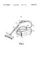
- FIG. 1is a perspective view of an illustrative embodiment of a canister vacuum cleaner using the electronic control system of the present invention
- FIG. 2is a top view of a portion of the handle of the vacuum cleaner of FIG. 1, showing the vacuum cleaner control panel;
- FIG. 3is a schematic diagram of an illustrative embodiment of the electronic control system of the present invention.
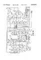
- FIG. 4is a logic circuit diagram of an illustrative embodiment of the electronic control system of the present invention.
- FIG. 5is an exploded perspective view of a portion of the handle of the vacuum cleaner of FIG. 1;
- FIG. 6is a perspective view of an illustrative optical device and a lens unit
- FIG. 7is a further perspective view of the illustrative optical device and lens unit shown in FIG. 6;
- FIG. 8is a cross-sectional side view of the optical device and lens unit of FIGS. 6 and 7, shown with the optical device mounted inside the lens unit;
- FIG. 9is a cross-sectional view of a portion of the handle of the vacuum cleaner of FIG. 1 showing the optical path of light emitted from the light-emitting diode;
- FIG. 10is a circuit diagram of an illustrative embodiment of a portion of the electronic control system used to process signals from the dust sensor;
- FIG. 11is an illustrative flow chart showing the logical flow of the routines executed by the control unit of the electronic control system of the present invention.
- FIG. 12is a circuit diagram of an illustrative embodiment of a portion of the circuitry used to encode sensor data
- FIG. 13is a circuit diagram of an illustrative embodiment of a portion of the circuitry used to decode sensor data that is encoded by the circuitry shown in FIG. 12;
- FIG. 14is a circuit diagram showing the use of an illustrative microcontroller.
- vacuum cleaner 20shown in FIG. 1, is provided with an electronic control system for controlling the operation of the vacuum cleaner 20.
- Vacuum cleaner 20is preferably a canister vacuum cleaner having a nozzle 22 with a powered rotary brush, as well as other cleaning attachments (not shown).
- dust-laden airis drawn into canister 24 and collected in bag 25 after passing through nozzle 22 (or other attachment), wand 26, handle 28, and hose 30.
- the handle 28has an electronic control panel 32 that allows the user to select various vacuum cleaner functions.
- Electronic control panel 32is shown in more detail in FIG. 2.
- the usercan turn on the vacuum cleaner 20 by pressing either ON (CARPET) switch 34 or the ON (FLOOR) switch 36.
- ON (CARPET) switch 34is pressed, the suction motor of vacuum cleaner 20 is turned on and the power brush in nozzle 22 is turned on, so that a carpet may be cleaned effectively.
- 0N (FLOOR) switch 36is pressed, the suction motor of vacuum cleaner 20 is turned on, but the power brush in nozzle 22 remains off, so that a bare floor can be cleaned.
- ON (FLOOR) switch 36is also preferably used when other attachments are used in place of nozzle 22, to avoid energizing the conductors in wand 26 unnecessarily.
- Indicator light 38is lit when 0N (CARPET) switch 34 is depressed and indicator light 40 is lit when ON (FLOOR) switch 36 is depressed. After the carpet or floor has been cleaned, vacuum cleaner 20 may be turned off using OFF switch 42. If vacuum cleaner 20 is plugged into an active power outlet, indicator light 44 is lit to show that the vacuum cleaner is ready to be turned on, even though presently off.
- 0NCARPET
- FLOORON
- the usermay manually select the desired vacuum cleaner power setting by depressing HIGH switch 46 for high power, MED switch 48 for medium power, or LOW switch 50 for low power.
- Indicator lights 52, 54, and 56are used to indicate which power setting has been selected.
- the default power settingis high power.
- the electronic control system of vacuum cleaner 20also supports an automatic mode in which the control system automatically adjusts the power setting. The automatic mode may be invoked by pressing AUTO switch 58. When vacuum cleaner 20 is in the automatic mode, indicator light 60 is lit.
- Another user-selectable featureis the bag-change mode. If the user presses MAX SUCTION switch 62, the electronic control system of vacuum cleaner 20 will shut off vacuum cleaner 20 when the vacuum cleaner suction power has been discernibly degraded. If MAX FILL switch 64 is pressed, the electronic control system of vacuum cleaner 20 will shut off vacuum cleaner 20 only after the bag has filled to the maximum extent allowable. Indicator lights 66 and 68 light to indicate whether the maximum suction or the maximum fill mode has been selected.
- a schematic block diagram of electronic control system 70is shown in FIG. 3.
- a central component of electronic control system 70is control unit 72, which is mounted in handle 28.
- control unit 72contains the circuitry necessary to provide an interface with the user, including the switches and indicators and accompanying circuitry of electronic control panel 32.
- Control unit 72also contains circuitry for controlling the power to nozzle 22 and the vacuum cleaner suction motor in motor assembly 74. Additional circuitry within control unit 72 is used to receive signals from various sensors in door assembly 76. Both motor assembly 74, which contains the vacuum cleaner suction motor, and door assembly 76, are contained within vacuum cleaner canister 24.
- control unit 72contains microcontroller 78, power supply 80, control switch and indicator circuitry 82, decoder circuit 84, power nozzle control circuit 86, and dust detection circuit 88. Attached to the dust detection circuit 88 is dust sensor 90.
- Control unit 72further includes suction motor drive circuit 156.
- Motor assembly 74contains suction motor 92 and triac module 94.
- Door assembly 76contains door switch module 98 and door switch 100.
- Power nozzle 22contains nozzle motor 102 for driving the nozzle brush (not shown).
- Control unit 72is connected to motor assembly 74 and door assembly 76 by wires 106, which are contained within hose 30 (FIG. 1).
- Line wire 108 and neutral wire 110are used to carry power from the AC input throughout the electronic control system 70.
- Code wires 112 and 114 and neutral wire 110support two-way communications between control unit 72 and the motor and door assemblies 74 and 76.
- Code wire 112(with neutral wire 110) carries control signals from control unit 72 to motor assembly 74.
- Code wire 114(with neutral wire 110) is used to carry encoded signals from the encoding circuitry of door assembly 76 to control unit 72 when the hose 30 is connected to intake port 162 (FIG. 1). In this configuration, code wire 114 is connected to door assembly 76 via terminal 164.
- code wire 114is connected to door assembly 76 via terminal 168.
- Microcontroller 78has on-board memory that contains routines that allow microcontroller 78 to control the power that is applied to nozzle motor 102 and suction motor 92 in response to input signals received from the switches on electronic control panel 32 and various sensors. Microcontroller 78 monitors the state of the switches in the switch and indicator circuitry 82 to determine which mode of operation has been selected by the user. For example, when 0N (CARPET) switch 38 has been pressed, microcontroller 78 applies power to nozzle motor 102 and suction motor 92. Microcontroller 78 receives encoded signals from door assembly 76, which indicate whether the bag should be changed or whether the door is open. In the automatic mode of operation, microcontroller 78 determines the appropriate power setting for suction motor 92 based on the frequency with which dust particles are detected to be flowing through handle 28.
- 0NCARPET
- Vacuum cleaner 20preferably operates at discrete power settings: low (75 V RMS ), medium (90 V RMS ), medium-high (105 V RMS --not available manually), or high (120 V RMS ).
- the medium powerpreferably will initially be applied followed by a smooth increase over a period of approximately 0.5 s to the high setting, thereby avoiding a current surge.
- microcontroller 78preferably adjusts the vacuum cleaner power setting, initially setting the vacuum cleaner power to "low".
- the vacuum cleaner powerpreferably is raised to the next highest setting after a predetermined delay.
- the next lowest settingpreferably is selected after a predetermined delay.
- vacuum cleaner 20preferably uses optical dust sensor 90 to generate a signal proportional to the number of dust particles that are drawn into vacuum cleaner 20 per unit time.
- dust sensor 90preferably has a light source--light-emitting diode 116--and a photodetector--phototransistor 118, which are preferably mounted on opposite sides of an air passageway 120, which extends through handle 28.
- light-emitting diode 116is an inexpensive emitter, such as Part No. IRL 80A, available from Siemens Components Corporation of Cupertino, California.
- Phototransistor 118is preferably an inexpensive high-sensitivity phototransistor, such as Part No. LPT-80A, also available from Siemens Components Corporation.
- Inner surface 71 of handle 28defines the air passageway 120.
- Light-emitting diode 116is preferably mounted in a lens unit 122.
- Phototransistor 118may preferably be mounted in an identical lens unit 123.
- Lens units 122 and 123are preferably a one-piece components that are not only used to hold the light-emitting diode 116 and phototransistor 118, but also contain integrally formed lenses for focusing the light.
- Lens unit 122is used to focus the light emitted from light-emitting diode 116 toward phototransistor 118. When the light from the light-emitting diode 116 reaches lens unit 123, it is focused onto the phototransistor 118 by lens unit 123. Using lens unit 122 reduces the diameter of the emitted light beam as it impinges the lens unit 123 from approximately 0.4 inches (1 cm) to approximately (0.08 inches (2 mm). Lens unit 123 further focuses the beam onto phototransistor 118.
- lens units 122 and 123are formed from an optical-grade polycarbonate, which transmits light at least in a wavelength range of about 800 nm to 1000 nm.
- FIGS. 6 and 7,show optical device 127, which can be either light emitting diode 116 or phototransistor 118. If optical device 127 is a light emitting diode, light is emitted via a hemispherical lens 129 that is part of the packaged optical device 127. If optical device 127 is a phototransistor 118, light is received via the hemispherical lens 129.
- optical device 127can be either light emitting diode 116 or phototransistor 118.
- upper wall 135has slots 131 that accommodate the leads 133 of optical device 127, when optical device 127 is mounted in lens unit 125.
- Upper wall 135 and lower wall 137restrict vertical motion of optical device 127 with respect to lens unit 125.
- Side walls 139 and 141restrict lateral horizontal motion.
- the optical device 127can be mounted in lens unit 125 by snapping the optical device 127 into place.
- Lens unit 125has wedge-shaped ridge 143, which biases optical device 127 against ridge 147 after optical device 127 is snapped into place past the ridge 143.
- Lens unit 125preferably has an integrally formed lens 149, which is shown in cross-section in FIG. 8.
- Lens 149preferably has a first face that has a radius of curvature of approximately 0.24 inches (0.6 cm) and a second face that has a radius of curvature of approximately 0.115 inches (0.3 cm).
- lens 129 and lens 149are separated by an air gap. Preferably this gap is approximately 0.018 inches (0.5 mm).
- the path of the light emitted from light-emitting diode 116 across passageway 120is shown in FIG. 9.
- the diameter of passageway 120is preferably approximately 1.25 inches (3 cm).
- lens portion 97 of lens unit 123focuses the light onto the light-sensitive portion of phototransistor 118 via hemispherical lens 157.
- the lens units 122 and 123are mounted so that the lens portions 96 and 97 of these devices are flush with inner surface 159 of passageway 120.
- light-emitting diode 116In automatic mode, light is emitted by light-emitting diode 116 at a constant intensity. As shown in FIG. 10, the intensity of the light emitted by light-emitting diode 116 is controlled by microcontroller 78 (FIG. 4) via control terminal 126. The light emitted by light-emitting diode 116 is received by phototransistor 118, which generates corresponding phototransistor output signals. When a dust particle passes between light-emitting diode 116 and phototransistor 118, the intensity of the light from light-emitting diode 116 that is received by phototransistor 118 is momentarily reduced, causing the phototransistor output signal to drop.
- the dust detection circuit 88contains a two-stage analog amplifier 124, as shown in FIG. 10.
- Two-stage analog amplifier 124processes the phototransistor output signals, so that microcontroller 78 (FIG. 4) can recognize the flow rate of the particles being drawn through passageway 120.
- the phototransistor output signal from phototransistor 118preferably is passed to amplifier 128 via capacitor 117, which blocks low-frequency signal transients, such as those occurring more slowly than approximately 1 ms. Because capacitor 117 blocks low-frequency signals, two-state analog amplifier 124 effectively detects the leading edges of the signals produced as dust particles pass between light-emitting diode 116 and phototransistor 118.
- both the leading and trailing edgesmay be detected.
- the intensity of the light from light-emitting diode 116 that is received by phototransistor 118is abruptly reduced. This transient signal is passed to amplifier 128 via capacitor 117.
- the transient signals that are received by amplifier 128are amplified and passed to comparator 132. If the amplified output of phototransistor 118 exceeds the threshold set by resistor 130, comparator 132 will generate a corresponding output pulse, which is strengthened to a level sufficient to be received by microcontroller 78 by output amplifier 134. The processed phototransistor output signal is provided to microcontroller 78 via output terminal 136.
- Microcontroller 78preferably measures the average time period between dust particle edge detections, which generally corresponds to the average time period between detected dust particles. The microcontroller 78 measures this time period as shown in FIG. 11.
- two-stage analog amplifier 124detects a dust particle and generates an output pulse.
- Microcontroller 78measures an initial time, T INITIAL , at step 140 using an internal clock. After detecting another dust particle at step 142, microcontroller 78 increments a counter at step 144 to reflect that a dust particle was detected at step 142.
- microcontroller 78tests to determine whether the count is equal to a predetermined limit, N, where N is preferably 20 (at step 140, the value of count is zero).
- microcontroller 78When ⁇ AVG is between 5 and 7 ms the medium-high setting preferably is used. For values of ⁇ AVG less than 5 ms, the highest power setting preferably is selected. After adjusting the power setting, microcontroller 78 preferably waits at step 154 for a predetermined time, for example, two seconds, before looping back to step 138. The two second delay ensures that microcontroller 78 does not adjust the power setting too frequently.
- Microcontroller 78preferably controls the power delivered to suction motor 92 using a conventional triac module 94, as shown in FIG. 4.
- Triac module 94applies power to suction motor 92 from line wire 108 and neutral wire 110 in response to control signals that are generated by suction motor drive circuit 156 under the direction of microcontroller 78.
- the control signals from suction motor drive circuit 156are provided to triac module 94 via code wire 112 and neutral wire 110.
- Microcontroller 78preferably determines whether or not power is delivered to nozzle motor 102 using a conventional triac circuit contained within power nozzle drive circuit 86.
- Door assembly 76(FIGS. 4 and 12) preferably contains various sensors for measuring parameters that are related to the operation of vacuum cleaner 20, such as whether or not bag 25 is present, the pressure drop across bag 25 (FIG. 1), and the state of door 174 (open or closed).
- Control unit 72preferably monitors the outputs of the sensors and controls the power applied to suction motor 92 and nozzle motor 102 in response. If desired, additional sensors can be provided, either in door assembly 76 or elsewhere, to monitor motor temperature, motor speed, airflow rate, etc., and react accordingly.
- door assembly 76preferably contains two normally open vacuum pressure switches 158 and 160 that monitor the differential pressure across the bag (i.e. from just before the bag inlet to the exhaust side of the bag). As the bag fills, the bag becomes clogged with dust, causing the magnitude of the pressure drop across the bag to increase. When the pressure drop exceeds a first threshold level--for example, 42 inches of water--vacuum switch 158 closes, which alters the voltage provided to decoder circuit 84 in control unit 72 via code wire 114 and neutral wire 110. By decoding the value of this voltage, microcontroller 78 can determine that the pressure drop has exceeded the first threshold.
- a first threshold level--for example, 42 inches of water--vacuum switch 158closes, which alters the voltage provided to decoder circuit 84 in control unit 72 via code wire 114 and neutral wire 110.
- microcontroller 78shuts off the power to suction motor 92 at this point. If, however, the "maximum fill” mode has been selected, the bag is allowed to fill until the pressure drop exceeds a second threshold level-for example, 57 inches of water. When the second threshold is exceeded, vacuum switch 160 closes, which further alters the voltage provided to decoder circuit 84 in control unit 72. In response, microcontroller 78 shuts off power to suction motor 92, because suction power is substantially degraded whenever the pressure drop across the bag is greater than 57 inches of water.
- the circuitry of door assembly 76is shown in more detail in FIG. 12.
- code wire 114When hose 30 is connected to intake port 162 (FIG. 1), code wire 114 connects to terminal 164 in intake port 162, whereas when hose 30 is connected to blow port 166 (FIG. 1), code wire 114 is connected to terminal 168 in blow port 166.
- the pressure drop across the bag of vacuum cleaner 20is monitored by vacuum switches 158 and 160. If the pressure drop exceeds 42 inches of water, vacuum switch 158 will close, which changes the resistance between terminal 164 and terminal 170 from 4 k ⁇ to 3 k ⁇ .
- This changeis detected by decoder circuit 84, so that if vacuum cleaner 20 is in the maximum suction mode, power to suction motor 92 can be shut off and indicator light 66 can be repeatedly turned on and off (FIG. 4).
- vacuum switch 160closes, so that the resistance between terminal 164 and terminal 170 drops to 1 k ⁇ .
- the decoder circuit 84detects this change and, if vacuum cleaner 20 is in the maximum fill mode, power is shut off to suction motor 92 and indicator light 68 is repeatedly turned on and off.
- code wire 112, neutral wire 110, and line wire 108 in hose 30are also connected to motor assembly 74 and door assembly 76 in the same way that these wires are connected when hose 30 is connected to intake port 162.
- blow port 166that allows a full set of electrical connections to be made between wires 106 and motor assembly 74 and door assembly 76, the user can control vacuum cleaner 20 using electronic control panel 32 on handle 28, even when the vacuum cleaner 20 is being used in the blow port mode.
- the resistance between code wire 114 and neutral wire 110will be 1 k ⁇ (the resistance of resistor 172). If a resistance of 1 k ⁇ is detected before power is applied to suction motor 92, microcontroller 78 will recognize that blow port 166 is in use and will only allow OFF switch 42, LOW switch 50, MED switch 48, and HIGH switch 46 to be operational. When using the blow port 166, it is only necessary to press LOW switch 50, MED switch 48, or HIGH switch 46 to turn on the vacuum cleaner 20.
- the OFF switch 42can be used to turn off the vacuum cleaner 20, as usual.
- microcontroller 78directs power nozzle drive circuit 86 to cut off power normally supplied to the nozzle 22, so that the electrical terminals of handle 28 that are used to connect handle 28 to wand 26 and nozzle 22 are not needlessly energized.
- Door switch 176is mounted on door 174 (FIG. 1) so that when door 174 is closed and bag 25 is in place, a flat portion of bag 25 will bias door switch 176 into a closed position. When either door 174 is open or bag 25 is missing, door switch 176 will return to a normally-open position. When microcontroller 78 detects that door switch 176 is open, no power will be applied to suction motor 92 (FIG. 1) to prevent damage to suction motor 92 from foreign objects entering through the area of the door 174. Indicator light 44 will also be repeatedly turned on and off.
- the decoder circuit 84which determines the state of vacuum switches 158 and 160 and door switch 176, is shown in more detail in FIG. 13.
- Terminal 178is connected to code wire 114, which is connected to either terminal 164 or 168 (FIG. 12), depending on whether hose 30 is attached to intake port 162 or blow port 166.
- Comparators 180, 182, and 184are connected to terminal 178, so that the voltage on terminal 178, which is indicative of the resistance between terminal 170 and either terminal 164 or 168 (FIG. 12), can be monitored.
- the outputs of comparators 180, 182, and 184are provided to microcontroller 78 via terminals 186, 188, and 190, respectively.
- outputs 186, 188, and 190are low. Whenever output 186 is low, it will be apparent to microcontroller 78 that door 174 is open, so that the power to vacuum cleaner 20 can be shut off. Output 186 is high when door 174 is closed. Output 188 is high whenever vacuum switch 158 is closed, indicating that the pressure drop across the vacuum cleaner bag is greater than 42 inches of water. Output 190 is high whenever vacuum switch 160 is closed, which occurs when the pressure drop across the bag is greater than 57 inches of water. If microcontroller 78 senses that outputs 188 and 190 are high before power has been applied to suction motor 92, microcontroller 78 will be able to determine that hose 30 is connected to blow port 166 rather than intake port 162.
- Microcontroller 78receives the signals provided at outputs 186, 188, and 190 (FIG. 13) at inputs 192, 194, and 196, respectively (FIG. 14).
- One of the advantages of the arrangement of electronic control system 70is that because microcontroller 78 is located in handle 28 (FIG. 1) rather than canister 24 (FIG. 1), few wires are required between handle 28 and canister 24. Specifically, it is only necessary to provide four wires 106 (FIG.
- microcontroller 78is a 4 bit microcontroller with 1024 ⁇ 8 bits of program memory and 64 ⁇ 4 bits of data memory, such as part No. ⁇ PD 7566, available from NEC Corporation of Japan. As shown in FIG. 14, microcontroller 78 monitors the pulses generated by dust detection circuit 88 at pin 198. Pin 200 is used to detect whether the input voltage on line wire 108 is positive or negative with respect to neutral wire 110, which allows microcontroller timing to be derived from the 50 or 60 Hz input voltage. (Operation at 50 or 60 Hz is a factory selectable option).
- Microcontroller 78scans the switches 34, 36, 42, 46, 48, 50, 58, 62, and 64 each input voltage cycle using pins 202, 204, and 206, in conjunction with the scan outputs at pins 208, 210, and 212, to determine which switches have been pressed by the user.
- the states of switches 42, 36, and 34are read while pin 210 is low and pins 212 and 208 are high.
- the states of switches 46, 48, and 50are read while pin 212 is low and pins 210 and 208 are high.
- the states of switches 58, 64, and 62are read while pin 208 is low and pins 210 and 212 are high.
- the indicator lightspreferably are controlled in a similar fashion.
- transistor 240is on and the status of indicator lights 44, 40, and 38 is determined by the states of transistors 242, 244, 246, and 248.
- transistor 250is on and the status of indicator lights 52, 54, 56, and 60 is determined by the states of transistors 242, 244, 246, and 248.
- transistor 252is on and the status of indicator lights 66 and 68 is determined by the states of transistors 242, 244, 246, and 248.
- Pin 214is used to control the power applied to nozzle motor 102 by power nozzle drive circuit 86.
- Pin 216is used to direct suction motor drive circuit 156 to generate control signals that cause triac module 94 to apply the desired power to suction motor 92.
- the output from clock oscillator 218is supplied to microcontroller 78 via pins 220 and 222, which allows microcontroller 78 to execute control routines at a clock speed of 500 kHz.
- Power supply 80 of control unit 72 (FIG. 4), which supplies power to microcontroller 78 via pin 224,is preferably a conventional dual-voltage power supply circuit of the non-isolated type.
- Capacitor 226 and resistor 228form a reset delay circuit. When power is first applied to microcontroller 78, capacitor 226 discharges and microcontroller 78 is reset via pin 230. Pins 232, 234, and 236 of microcontroller 78 control indicator lights 38, 40, 44, 52, 54, 56, 66, and 68.
- the status of dust sensor 90is checked by repeatedly turning light-emitting diode 116 (FIG. 5) on and off using terminal 238, which is connected to control terminal 126 (FIG. 5).
- Microcontroller 78attempts to detect each resulting pulse at terminal 200. If a pulse is missed indicating that the dust sensor 90 is obstructed by dust, microcontroller 78 will not enable the automatic mode. If the automatic mode is subsequently selected, indicator light 60 will be repeatedly turned on and off and power will be cut off to nozzle motor 102 and suction motor 92. Upon selecting one of the LOW, MED, or HIGH power settings, indicator light 60 will be extinguished. The automatic mode may, however, be selected after vacuum cleaner 20 has been turned off and the dust blocking dust sensor 90 has been cleared.
- an improved electronic control system for a vacuum cleanerin which a microcontroller-based control unit contained in the handle of the vacuum cleaner is connected to the canister by a wired hose, which supports two-way communications between the control unit and the suction motor and various sensors contained in the canister, thereby allowing a single microcontroller to be used, simplifying the construction of the unit.
- the vacuum cleanercan be placed in one of two user-selectable bag change modes: a maximum suction bag change mode, in which the vacuum cleaner shuts off when the pressure drop across the vacuum cleaner bag exceeds a predetermined threshold and a maximum fill bag change mode, in which the vacuum cleaner shuts off only after the pressure drop exceeds a higher threshold.
- the vacuum cleaneralso has an optical dust sensor located in the handle of the vacuum cleaner, so that the vacuum cleaner can be placed in an automatic mode in which the power setting of the suction motor is adjusted based on the frequency with which dust particles are drawn past the sensor.
- the optical dust sensoris constructed from a light source and a photodetector, each of which is mounted in a lens unit having an integrally formed lens.
- the vacuum cleanerhas a blow port to which a vacuum cleaner hose can be attached and circuitry for detecting when the hose is connected to the blow port.
Landscapes
- Engineering & Computer Science (AREA)
- Mechanical Engineering (AREA)
- Electric Vacuum Cleaner (AREA)
Abstract
Description
Claims (11)
Priority Applications (1)
| Application Number | Priority Date | Filing Date | Title |
|---|---|---|---|
| US08/455,670US5515572A (en) | 1994-05-12 | 1995-05-31 | Electronic vacuum cleaner control system |
Applications Claiming Priority (2)
| Application Number | Priority Date | Filing Date | Title |
|---|---|---|---|
| US08/241,578US5507067A (en) | 1994-05-12 | 1994-05-12 | Electronic vacuum cleaner control system |
| US08/455,670US5515572A (en) | 1994-05-12 | 1995-05-31 | Electronic vacuum cleaner control system |
Related Parent Applications (1)
| Application Number | Title | Priority Date | Filing Date |
|---|---|---|---|
| US08/241,578DivisionUS5507067A (en) | 1994-05-12 | 1994-05-12 | Electronic vacuum cleaner control system |
Publications (1)
| Publication Number | Publication Date |
|---|---|
| US5515572Atrue US5515572A (en) | 1996-05-14 |
Family
ID=22911268
Family Applications (3)
| Application Number | Title | Priority Date | Filing Date |
|---|---|---|---|
| US08/241,578Expired - Fee RelatedUS5507067A (en) | 1994-05-12 | 1994-05-12 | Electronic vacuum cleaner control system |
| US08/455,983Expired - Fee RelatedUS5542146A (en) | 1994-05-12 | 1995-05-31 | Electronic vacuum cleaner control system |
| US08/455,670Expired - Fee RelatedUS5515572A (en) | 1994-05-12 | 1995-05-31 | Electronic vacuum cleaner control system |
Family Applications Before (2)
| Application Number | Title | Priority Date | Filing Date |
|---|---|---|---|
| US08/241,578Expired - Fee RelatedUS5507067A (en) | 1994-05-12 | 1994-05-12 | Electronic vacuum cleaner control system |
| US08/455,983Expired - Fee RelatedUS5542146A (en) | 1994-05-12 | 1995-05-31 | Electronic vacuum cleaner control system |
Country Status (6)
| Country | Link |
|---|---|
| US (3) | US5507067A (en) |
| EP (1) | EP0681808A3 (en) |
| JP (1) | JPH0838408A (en) |
| CA (1) | CA2149187A1 (en) |
| CZ (1) | CZ121095A3 (en) |
| PL (1) | PL308579A1 (en) |
Cited By (68)
| Publication number | Priority date | Publication date | Assignee | Title |
|---|---|---|---|---|
| US6055702A (en)* | 1996-11-27 | 2000-05-02 | Yashima Electric Co., Ltd. | Vacuum cleaner |
| US6484348B1 (en) | 2000-09-29 | 2002-11-26 | Oreck Holdings, Llc | Vacuum devices having integrated cord storage and pivotable tool holders |
| US20040187249A1 (en)* | 2002-01-03 | 2004-09-30 | Jones Joseph L. | Autonomous floor-cleaning robot |
| US20050162119A1 (en)* | 2004-01-28 | 2005-07-28 | Landry Gregg W. | Debris sensor for cleaning apparatus |
| US20050160556A1 (en)* | 2004-01-23 | 2005-07-28 | Hitzelberger J. E. | Floor care apparatus with multiple agitator speeds and constant suction power |
| WO2005083541A1 (en)* | 2004-01-28 | 2005-09-09 | Irobot Corporation | Debris sensor for cleaning apparatus |
| US20050251292A1 (en)* | 2000-01-24 | 2005-11-10 | Irobot Corporation | Obstacle following sensor scheme for a mobile robot |
| US20050254185A1 (en)* | 2004-05-12 | 2005-11-17 | Cunningham J V | Central vacuum cleaning system control subsystems |
| US20050287038A1 (en)* | 2004-06-24 | 2005-12-29 | Zivthan Dubrovsky | Remote control scheduler and method for autonomous robotic device |
| US20060190134A1 (en)* | 2005-02-18 | 2006-08-24 | Irobot Corporation | Autonomous surface cleaning robot for wet and dry cleaning |
| US7155308B2 (en) | 2000-01-24 | 2006-12-26 | Irobot Corporation | Robot obstacle detection system |
| US20070079469A1 (en)* | 2005-10-07 | 2007-04-12 | Cube Investments Limited | Integrated central vacuum cleaner suction device and control |
| US20070079467A1 (en)* | 2005-10-07 | 2007-04-12 | Cube Investments Limited | Central vacuum cleaner cross-controls |
| US20070094839A1 (en)* | 2005-11-03 | 2007-05-03 | The Scott Fetzer Company | Cleaning apparatus with removable handle |
| USD544304S1 (en) | 2005-06-06 | 2007-06-12 | Robert Gordon Industries, Ltd. | Travel mug |
| US20070151068A1 (en)* | 2006-01-05 | 2007-07-05 | The Scott Fetzer Company | Motor control for a vacuum cleaner |
| US20070234492A1 (en)* | 2005-12-02 | 2007-10-11 | Irobot Corporation | Coverage robot mobility |
| US20070244610A1 (en)* | 2005-12-02 | 2007-10-18 | Ozick Daniel N | Autonomous coverage robot navigation system |
| US20080015738A1 (en)* | 2000-01-24 | 2008-01-17 | Irobot Corporation | Obstacle Following Sensor Scheme for a mobile robot |
| US20080039974A1 (en)* | 2006-03-17 | 2008-02-14 | Irobot Corporation | Robot Confinement |
| US7332890B2 (en) | 2004-01-21 | 2008-02-19 | Irobot Corporation | Autonomous robot auto-docking and energy management systems and methods |
| US20080052846A1 (en)* | 2006-05-19 | 2008-03-06 | Irobot Corporation | Cleaning robot roller processing |
| US20080084174A1 (en)* | 2001-01-24 | 2008-04-10 | Irobot Corporation | Robot Confinement |
| US7388343B2 (en) | 2001-06-12 | 2008-06-17 | Irobot Corporation | Method and system for multi-mode coverage for an autonomous robot |
| US20080229885A1 (en)* | 2007-03-22 | 2008-09-25 | Mah Pat Y | Jar opener |
| US20080301903A1 (en)* | 2004-09-17 | 2008-12-11 | Cube Investments Limited | Cleaner Handle and Cleaner Handle Housing Sections |
| US7620476B2 (en) | 2005-02-18 | 2009-11-17 | Irobot Corporation | Autonomous surface cleaning robot for dry cleaning |
| US7706917B1 (en) | 2004-07-07 | 2010-04-27 | Irobot Corporation | Celestial navigation system for an autonomous robot |
| US7761954B2 (en) | 2005-02-18 | 2010-07-27 | Irobot Corporation | Autonomous surface cleaning robot for wet and dry cleaning |
| US20100236013A1 (en)* | 2009-03-17 | 2010-09-23 | Electrolux Home Care Products, Inc. | Vacuum Cleaner Sensor |
| US8096014B2 (en) | 2005-10-07 | 2012-01-17 | Cube Investments Limited | Central vacuum cleaner control, unit and system with contaminant sensor |
| US8239992B2 (en) | 2007-05-09 | 2012-08-14 | Irobot Corporation | Compact autonomous coverage robot |
| US8374721B2 (en) | 2005-12-02 | 2013-02-12 | Irobot Corporation | Robot system |
| US8386081B2 (en) | 2002-09-13 | 2013-02-26 | Irobot Corporation | Navigational control system for a robotic device |
| US8382906B2 (en) | 2005-02-18 | 2013-02-26 | Irobot Corporation | Autonomous surface cleaning robot for wet cleaning |
| US8396592B2 (en) | 2001-06-12 | 2013-03-12 | Irobot Corporation | Method and system for multi-mode coverage for an autonomous robot |
| US8417383B2 (en) | 2006-05-31 | 2013-04-09 | Irobot Corporation | Detecting robot stasis |
| US8515578B2 (en) | 2002-09-13 | 2013-08-20 | Irobot Corporation | Navigational control system for a robotic device |
| US8584305B2 (en) | 2005-12-02 | 2013-11-19 | Irobot Corporation | Modular robot |
| US8683645B2 (en) | 2010-07-22 | 2014-04-01 | Sears Brands, L.L.C. | Vacuum cleaning device with air quality monitoring system |
| US8732895B2 (en) | 2005-10-07 | 2014-05-27 | Cube Investments Limited | Central vacuum cleaner multiple vacuum source control |
| US8742926B2 (en) | 2010-12-30 | 2014-06-03 | Irobot Corporation | Debris monitoring |
| US8780342B2 (en) | 2004-03-29 | 2014-07-15 | Irobot Corporation | Methods and apparatus for position estimation using reflected light sources |
| US8800107B2 (en) | 2010-02-16 | 2014-08-12 | Irobot Corporation | Vacuum brush |
| US8881339B2 (en) | 2011-04-29 | 2014-11-11 | Irobot Corporation | Robotic vacuum |
| US8930023B2 (en) | 2009-11-06 | 2015-01-06 | Irobot Corporation | Localization by learning of wave-signal distributions |
| US8972052B2 (en) | 2004-07-07 | 2015-03-03 | Irobot Corporation | Celestial navigation system for an autonomous vehicle |
| US9015897B2 (en) | 2010-06-29 | 2015-04-28 | Aktiebolaget Electrolux | Dust detection system |
| US9095244B2 (en) | 2010-06-29 | 2015-08-04 | Aktiebolaget Electrolux | Dust indicator for a vacuum cleaner |
| US9320398B2 (en) | 2005-12-02 | 2016-04-26 | Irobot Corporation | Autonomous coverage robots |
| US9420741B2 (en) | 2014-12-15 | 2016-08-23 | Irobot Corporation | Robot lawnmower mapping |
| US9510505B2 (en) | 2014-10-10 | 2016-12-06 | Irobot Corporation | Autonomous robot localization |
| US9516806B2 (en) | 2014-10-10 | 2016-12-13 | Irobot Corporation | Robotic lawn mowing boundary determination |
| US9538702B2 (en) | 2014-12-22 | 2017-01-10 | Irobot Corporation | Robotic mowing of separated lawn areas |
| US9554508B2 (en) | 2014-03-31 | 2017-01-31 | Irobot Corporation | Autonomous mobile robot |
| US9649000B2 (en) | 2012-11-09 | 2017-05-16 | Aktiebolaget Electrolux | Cyclone dust separator arrangement, cyclone dust separator and cyclone vacuum cleaner |
| US9949608B2 (en) | 2002-09-13 | 2018-04-24 | Irobot Corporation | Navigational control system for a robotic device |
| US10021830B2 (en) | 2016-02-02 | 2018-07-17 | Irobot Corporation | Blade assembly for a grass cutting mobile robot |
| US20190010686A1 (en)* | 2017-07-10 | 2019-01-10 | Darrel Hughes | Pipe unclogging device and Attachments |
| US10459063B2 (en) | 2016-02-16 | 2019-10-29 | Irobot Corporation | Ranging and angle of arrival antenna system for a mobile robot |
| US10512384B2 (en) | 2016-12-15 | 2019-12-24 | Irobot Corporation | Cleaning roller for cleaning robots |
| US10595624B2 (en) | 2017-07-25 | 2020-03-24 | Irobot Corporation | Cleaning roller for cleaning robots |
| US11115798B2 (en) | 2015-07-23 | 2021-09-07 | Irobot Corporation | Pairing a beacon with a mobile robot |
| US11109727B2 (en) | 2019-02-28 | 2021-09-07 | Irobot Corporation | Cleaning rollers for cleaning robots |
| US11471020B2 (en) | 2011-04-29 | 2022-10-18 | Irobot Corporation | Robotic vacuum cleaning system |
| US11470774B2 (en) | 2017-07-14 | 2022-10-18 | Irobot Corporation | Blade assembly for a grass cutting mobile robot |
| US11484175B2 (en) | 2018-08-27 | 2022-11-01 | Techtronic Floor Care Technology Limited | Floor cleaner |
| US11647878B2 (en) | 2019-11-13 | 2023-05-16 | Emerson Electric Co. | Vacuum cleaner motor assemblies and methods of operating same |
Families Citing this family (79)
| Publication number | Priority date | Publication date | Assignee | Title |
|---|---|---|---|---|
| DE69618166T2 (en)* | 1995-08-25 | 2002-08-29 | Koninklijke Philips Electronics N.V., Eindhoven | VACUUM CLEANER WITH POWER REGULATION DEPENDING ON THE MODE OF OPERATION OF AN ELECTRIC BRUSH |
| CN1107481C (en)* | 1995-11-24 | 2003-05-07 | 皇家菲利浦电子有限公司 | Vacuum cleaners that include odor filters |
| US5925172A (en)* | 1996-06-11 | 1999-07-20 | Amway Corporation | Air treatment system |
| US5806238A (en)* | 1996-09-12 | 1998-09-15 | The United States Of America As Represented By The Secretary Of The Agriculture | Biological vacuum device to enhance environmental quality |
| WO1998028094A1 (en)* | 1996-12-24 | 1998-07-02 | Wang Kevin W | Carpet cleaning machine |
| US5819367A (en)* | 1997-02-25 | 1998-10-13 | Yashima Electric Co., Ltd. | Vacuum cleaner with optical sensor |
| US6023814A (en)* | 1997-09-15 | 2000-02-15 | Imamura; Nobuo | Vacuum cleaner |
| RU2152160C1 (en)* | 1998-01-06 | 2000-07-10 | Чепурина Наталья Николаевна | Vacuum cleaner control system |
| US5940928A (en)* | 1998-01-15 | 1999-08-24 | Tennant Company | Surface maintenance machine with computer controlled operational and maintenance systems |
| EP1021980B1 (en)* | 1998-09-30 | 2005-08-10 | STMicroelectronics S.r.l. | Method and device to recognise and indicate a discharge vessel filling level in a vacuum system |
| USD431335S (en)* | 1998-12-10 | 2000-09-26 | Matsushita Electric Corporation Of America | Vacuum cleaner handle |
| DE19900484A1 (en)* | 1999-01-08 | 2000-08-10 | Wap Reinigungssysteme | Measuring system for residual dust monitoring for safety vacuums |
| US7334350B2 (en)* | 1999-03-16 | 2008-02-26 | Anatomic Research, Inc | Removable rounded midsole structures and chambers with computer processor-controlled variable pressure |
| US6910245B2 (en)* | 2000-01-14 | 2005-06-28 | White Consolidated Industries, Inc. | Upright vacuum cleaner with cyclonic air path |
| US6558453B2 (en) | 2000-01-14 | 2003-05-06 | White Consolidated Industries, Inc. | Bagless dustcup |
| US6571422B1 (en)* | 2000-08-01 | 2003-06-03 | The Hoover Company | Vacuum cleaner with a microprocessor-based dirt detection circuit |
| US6771371B2 (en)* | 2000-08-10 | 2004-08-03 | Texas Instruments Incorporated | Particle detection and removal apparatus for use on wafer fabrication equipment to lower tool related defects from particle contamination |
| US6697658B2 (en) | 2001-07-02 | 2004-02-24 | Masimo Corporation | Low power pulse oximeter |
| WO2003058659A1 (en)* | 2002-01-08 | 2003-07-17 | BSH Bosch und Siemens Hausgeräte GmbH | Operating device for a household appliance, operating element and household appliance |
| DE10208366A1 (en)* | 2002-02-27 | 2003-09-04 | Bsh Bosch Siemens Hausgeraete | Vacuum cleaner with light guide element |
| KR20040038556A (en)* | 2002-11-01 | 2004-05-08 | 엘지전자 주식회사 | Up right vacuum cleaner |
| US6742222B2 (en) | 2002-11-05 | 2004-06-01 | Tonja L. Furr-Britt | Dual handle attachment for an appliance |
| US7220930B2 (en)* | 2003-01-28 | 2007-05-22 | The Hoover Company | Floor care appliance with an electro luminescent switch panel |
| US7599758B2 (en)* | 2003-09-19 | 2009-10-06 | Royal Appliance Mfg. Co. | Sensors and associated methods for controlling a vacuum cleaner |
| US7237298B2 (en)* | 2003-09-19 | 2007-07-03 | Royal Appliance Mfg. Co. | Sensors and associated methods for controlling a vacuum cleaner |
| US7424766B2 (en)* | 2003-09-19 | 2008-09-16 | Royal Appliance Mfg. Co. | Sensors and associated methods for controlling a vacuum cleaner |
| AU2012200539B2 (en)* | 2004-01-28 | 2014-10-23 | Irobot Corporation | Debris sensor for cleaning apparatus |
| US20060070206A1 (en)* | 2004-10-04 | 2006-04-06 | Panasonic Corporation Of North America | Floor cleaning apparatus with wireless control interface |
| US7647083B2 (en) | 2005-03-01 | 2010-01-12 | Masimo Laboratories, Inc. | Multiple wavelength sensor equalization |
| US20060264710A1 (en)* | 2005-05-02 | 2006-11-23 | Donald Spector | Surgical method and apparatus using suction to hold tissue |
| US8978197B2 (en) | 2009-03-13 | 2015-03-17 | Lg Electronics Inc. | Vacuum cleaner |
| DE102005041133B3 (en)* | 2005-08-30 | 2007-01-18 | Miele & Cie. Kg | Operation of vacuum cleaner with speed control, bag change display and dust bag recognition, reduces suction power when no bag identification is recognized |
| US7673368B2 (en) | 2005-10-18 | 2010-03-09 | Panasonic Corporation Of North America | Dust bag arrangement and filling indicator for floor care apparatus |
| JP4321511B2 (en)* | 2005-10-25 | 2009-08-26 | パナソニック株式会社 | Electric vacuum cleaner |
| US7770253B2 (en)* | 2005-12-10 | 2010-08-10 | Lg Electronics Inc. | Vacuum cleaner with removable dust collector, and methods of operating the same |
| US7882592B2 (en) | 2005-12-10 | 2011-02-08 | Lg Electronics Inc. | Vacuum cleaner |
| US7749295B2 (en) | 2005-12-10 | 2010-07-06 | Lg Electronics Inc. | Vacuum cleaner with removable dust collector, and methods of operating the same |
| US8012250B2 (en)* | 2005-12-10 | 2011-09-06 | Lg Electronics Inc. | Vacuum cleaner |
| US8544143B2 (en) | 2005-12-10 | 2013-10-01 | Lg Electronics Inc. | Vacuum cleaner with removable dust collector, and methods of operating the same |
| KR100876694B1 (en)* | 2006-09-06 | 2008-12-31 | 엘지전자 주식회사 | How to control the vacuum cleaner |
| US8281455B2 (en) | 2005-12-10 | 2012-10-09 | Lg Electronics Inc. | Vacuum cleaner |
| US8404034B2 (en)* | 2005-12-10 | 2013-03-26 | Lg Electronics Inc. | Vacuum cleaner and method of controlling the same |
| US7785396B2 (en) | 2005-12-10 | 2010-08-31 | Lg Electronics Inc. | Vacuum cleaner with removable dust collector, and methods of operating the same |
| US7987551B2 (en)* | 2005-12-10 | 2011-08-02 | Lg Electronics Inc. | Vacuum cleaner |
| WO2007076008A2 (en)* | 2005-12-22 | 2007-07-05 | Mears Technologies, Inc | Electronic device including a poled superlattice having a net electrical dipole moment and associated methods |
| US7694383B2 (en)* | 2006-01-06 | 2010-04-13 | The Scott Fetzer Company | Upright vacuum cleaner with removable power head |
| US7509707B2 (en)* | 2006-02-06 | 2009-03-31 | Panasonic Corporation Of North America | Floor cleaning apparatus with dirt detection sensor |
| US20070283521A1 (en)* | 2006-06-09 | 2007-12-13 | Electrolux Home Care Products Ltd. | Electronic control system for a vacuum system |
| EP1949842B1 (en)* | 2007-01-24 | 2015-03-04 | LG Electronics Inc. | Vacuum cleaner |
| US20100004518A1 (en) | 2008-07-03 | 2010-01-07 | Masimo Laboratories, Inc. | Heat sink for noninvasive medical sensor |
| US8515509B2 (en) | 2008-08-04 | 2013-08-20 | Cercacor Laboratories, Inc. | Multi-stream emitter for noninvasive measurement of blood constituents |
| US8528163B2 (en) | 2009-02-12 | 2013-09-10 | Lg Electronics Inc. | Vacuum cleaner |
| US8151409B2 (en)* | 2009-02-26 | 2012-04-10 | Lg Electronics Inc. | Vacuum cleaner |
| US8713752B2 (en) | 2009-03-13 | 2014-05-06 | Lg Electronics Inc. | Vacuum cleaner |
| US8107983B2 (en)* | 2009-03-16 | 2012-01-31 | Telefonaktiebolaget L M Ericsson | Systems and method for coordinated multipoint downlink transmissions |
| TWI399190B (en) | 2009-05-21 | 2013-06-21 | Ind Tech Res Inst | Cleaning apparatus and detecting method thereof |
| TWI403300B (en)* | 2009-11-16 | 2013-08-01 | Ind Tech Res Inst | Method for controlling cleaning apparatus |
| EP2386238B1 (en)* | 2010-03-23 | 2019-03-06 | Stein & Co. GmbH | Vacuum cleaner with an output-controlled suction engine |
| CN102462451B (en) | 2010-11-10 | 2015-04-22 | 财团法人工业技术研究院 | Vacuum cleaner and operation method thereof |
| US8726457B2 (en) | 2011-12-30 | 2014-05-20 | Techtronic Floor Care Technology Limited | Vacuum cleaner with display |
| DE112013001113T5 (en)* | 2012-02-24 | 2014-11-06 | Mitsubishi Electric Corporation | Semiconductor device and its manufacturing method |
| GB2507320B (en)* | 2012-10-26 | 2014-12-10 | Dyson Technology Ltd | Switching mechanism |
| DE102013102847A1 (en)* | 2013-03-20 | 2014-09-25 | Miele & Cie. Kg | Method for adjusting the performance of a vacuum cleaner fan, control device for implementing the method and vacuum cleaner with such a control device |
| JP6228054B2 (en)* | 2014-03-27 | 2017-11-08 | 株式会社アガツマ | Vacuum cleaner toy |
| CN103862382A (en)* | 2014-03-29 | 2014-06-18 | 玉环鑫峰环保设备厂 | Control system of polishing and dust sucking cabinet |
| TWM520874U (en)* | 2015-10-13 | 2016-05-01 | Lumiplus Technology Suzhou Co Ltd | Dust collection device |
| WO2018161018A1 (en) | 2017-03-03 | 2018-09-07 | Tti (Macao Commercial Offshore) Limited | Vacuum cleaner including a surface cleaning head having a display |
| US10918252B2 (en)* | 2017-07-27 | 2021-02-16 | Neato Robotics, Inc. | Dirt detection layer and laser backscatter dirt detection |
| WO2020006182A1 (en)* | 2018-06-27 | 2020-01-02 | Bissell Inc. | Surface cleaning apparatus |
| JP7119272B2 (en)* | 2018-10-12 | 2022-08-17 | アクチエボラゲット エレクトロルックス | vacuum cleaner |
| US11903553B2 (en)* | 2018-11-06 | 2024-02-20 | H-P Products, Inc. | Vacuum hose having an integrated switch |
| GB2578872B (en)* | 2018-11-09 | 2021-04-14 | Dyson Technology Ltd | Vacuum cleaner |
| KR102864642B1 (en) | 2019-09-06 | 2025-09-25 | 삼성전자주식회사 | Cleaner and control method thereof |
| WO2021146333A1 (en) | 2020-01-13 | 2021-07-22 | Masimo Corporation | Wearable device with physiological parameters monitoring |
| CN116172445A (en) | 2020-02-27 | 2023-05-30 | 北京石头创新科技有限公司 | Carpet identification method for cleaning robot |
| CN113303733B (en)* | 2020-02-27 | 2022-10-18 | 北京石头创新科技有限公司 | Cleaning robot |
| CN112471964A (en)* | 2020-11-25 | 2021-03-12 | 袁力 | Detection method for recognizing fullness of dust collecting box of dust collector |
| EP4370022A1 (en) | 2021-07-13 | 2024-05-22 | Masimo Corporation | Wearable device with physiological parameters monitoring |
| EP4226825A1 (en)* | 2022-02-14 | 2023-08-16 | Vorwerk & Co. Interholding GmbH | Suction device and method for determining a fill level of a filter device of a suction device |
Citations (97)
| Publication number | Priority date | Publication date | Assignee | Title |
|---|---|---|---|---|
| US3172743A (en)* | 1965-03-09 | Commercial vacuum cleaners | ||
| US3210793A (en)* | 1964-03-16 | 1965-10-12 | Westinghouse Electric Corp | Vacuum cleaner full bag indicator |
| US3333564A (en)* | 1966-06-28 | 1967-08-01 | Sunbeam Corp | Vacuum bag indicator |
| US3381652A (en)* | 1965-10-21 | 1968-05-07 | Nat Union Electric Corp | Visual-audible alarm for a vacuum cleaner |
| US3382524A (en)* | 1966-07-21 | 1968-05-14 | Honeywell Inc | Control for a vacuum cleaner system |
| US3577869A (en)* | 1967-08-09 | 1971-05-11 | Matsushita Electric Industrial Co Ltd | Electric vacuum cleaner |
| US3579706A (en)* | 1968-11-12 | 1971-05-25 | Whirlpool Co | Vacuum cleaner motor control |
| US3588943A (en)* | 1968-11-12 | 1971-06-29 | Whirlpool Co | Vacuum cleaner suction and brush control |
| US3745965A (en)* | 1972-05-31 | 1973-07-17 | Electrolux Ab | Vacuum cleaner having signal for indicating absence of dust bag |
| FR2197555A1 (en)* | 1972-09-06 | 1974-03-29 | Philips Nv | |
| USRE28268E (en)* | 1968-11-08 | 1974-12-10 | Device kor signaling need for cleaning orreplacing suctioncleaner dust bag | |
| US3936904A (en)* | 1974-06-03 | 1976-02-10 | Whirlpool Corporation | Vacuum cleaner clogged condition indicator |
| USRE28920E (en)* | 1971-12-28 | 1976-08-03 | Aktiebolaget Electrolux | Remote control for vacuum cleaner motor |
| US4001912A (en)* | 1975-01-31 | 1977-01-11 | Aktiebolaget Electrolux | Vacuum cleaner device |
| US4020525A (en)* | 1975-08-13 | 1977-05-03 | The Singer Company | Vacuum cleaner filter bag condition indicator |
| US4021879A (en)* | 1975-11-28 | 1977-05-10 | Consolidated Foods Corporation | Constant performance vacuum cleaner |
| US4060050A (en)* | 1975-08-29 | 1977-11-29 | Aktiebolaget Electrolux | Fill indicator for a vacuum cleaner dust collector |
| US4070170A (en)* | 1975-08-20 | 1978-01-24 | Aktiebolaget Electrolux | Combination dust container for vacuum cleaner and signalling device |
| US4100878A (en)* | 1975-12-05 | 1978-07-18 | Aktiebolaget Electrolux | Vacuum cleaner dust container filling indicator device |
| US4124916A (en)* | 1977-08-04 | 1978-11-14 | The Singer Company | Vacuum cleaner condition indicator and safety device |
| JPS5411990A (en)* | 1976-08-04 | 1979-01-29 | Hooker Chemicals Plastics Corp | Posttbulk polymerization method of polyvinyl halide and composition thereof |
| US4184225A (en)* | 1976-09-15 | 1980-01-22 | Aktiebolaget Electrolux | Vacuum cleaner dust bag and motor disconnect device |
| US4193292A (en)* | 1978-01-11 | 1980-03-18 | Aktiebolaget Electrolux | Indicating device for vacuum cleaners |
| US4199838A (en)* | 1977-09-15 | 1980-04-29 | Aktiebolaget Electrolux | Indicating device for vacuum cleaners |
| DE2900433B1 (en)* | 1979-01-08 | 1980-06-26 | Vorwerk Co Interholding | Optical level indicator for the dust bag of a vacuum cleaner |
| GB2046037A (en) | 1979-02-28 | 1980-11-05 | Beamco Inc | Electrical motor control system |
| US4233597A (en)* | 1977-03-19 | 1980-11-11 | Gerhard Kurz | Device indicating a state due to the pressure modification |
| US4330900A (en)* | 1979-06-06 | 1982-05-25 | Vorwerk & Co. Interholding Gmbh | Vacuum cleaner with filling-condition indicator |
| US4357729A (en)* | 1981-01-26 | 1982-11-09 | Whirlpool Corporation | Vacuum cleaner control |
| US4370690A (en)* | 1981-02-06 | 1983-01-25 | Whirlpool Corporation | Vacuum cleaner control |
| US4370776A (en)* | 1980-08-08 | 1983-02-01 | Progress-Elektrogerate Mauz & Pfeiffer Gmbh & Co. | Vacuum cleaner for household and industrial application |
| US4370777A (en)* | 1979-11-28 | 1983-02-01 | Duepro Ag | Electric motor control for vacuum cleaner |
| US4399585A (en)* | 1980-08-08 | 1983-08-23 | Progress-Elektrogerate Mauz & Pfeiffer Gmbh & Co. | Vacuum cleaner with constant air flow |
| US4416033A (en)* | 1981-10-08 | 1983-11-22 | The Hoover Company | Full bag indicator |
| US4419783A (en)* | 1981-06-18 | 1983-12-13 | Aktiebolaget Electrolux | Remote control for a vacuum cleaner motor |
| US4419782A (en)* | 1980-10-31 | 1983-12-13 | Vorwerk & Co Interholdung GmbH | Fill-up indication arrangement for a vacuum cleaner |
| US4473923A (en)* | 1982-05-10 | 1984-10-02 | Dayco Corporation | Vacuum cleaning tool adapter with electrical control means |
| US4481692A (en)* | 1983-03-29 | 1984-11-13 | Gerhard Kurz | Operating-condition indicator for vacuum cleaners |
| JPS6041891A (en)* | 1983-08-18 | 1985-03-05 | Victor Co Of Japan Ltd | Still picture reproducing device |
| JPS6058846A (en)* | 1983-09-12 | 1985-04-05 | 昭和電工株式会社 | Laminate |
| JPS6058850A (en)* | 1983-09-13 | 1985-04-05 | 株式会社興人 | Transparent conductive film having improved abrasion resistance |
| US4514874A (en)* | 1981-03-12 | 1985-05-07 | Gerhard Kurz | Device for automatically controlling the suction power of a vacuum cleaner |
| JPS6130603A (en)* | 1984-07-19 | 1986-02-12 | Nippon Yakin Kogyo Co Ltd | Pyramidal metallic chip and method and device for production thereof |
| JPS6135864A (en)* | 1984-07-28 | 1986-02-20 | Kinzo Kanda | Cyclone |
| JPS6142574A (en)* | 1984-08-03 | 1986-03-01 | Nippon Synthetic Chem Ind Co Ltd:The | Unsaturated polyester resin composition for coating |
| US4580311A (en)* | 1984-02-08 | 1986-04-08 | Gerhard Kurz | Protective device for dust collecting devices |
| US4601082A (en)* | 1984-02-08 | 1986-07-22 | Gerhard Kurz | Vacuum cleaner |
| US4611365A (en)* | 1983-02-12 | 1986-09-16 | Matsushita Electric Industrial Co., Ltd. | Vacuum cleaner |
| JPS6223428A (en)* | 1985-07-23 | 1987-01-31 | Toshiba Corp | Apparatus for denitrating waste gas |
| US4654924A (en)* | 1985-12-31 | 1987-04-07 | Whirlpool Corporation | Microcomputer control system for a canister vacuum cleaner |
| EP0224309A1 (en)* | 1985-11-22 | 1987-06-03 | Laboratoires D'electronique Philips | Suction cleaner provided with an automatic suction control device |
| US4680827A (en)* | 1985-09-28 | 1987-07-21 | Interlava Ag | Vacuum cleaner |
| DE3629346A1 (en)* | 1986-08-28 | 1988-03-10 | Interlava Ag | Apparatus for the determination and display of the degree of plugging of filters |
| US4733431A (en)* | 1986-12-09 | 1988-03-29 | Whirlpool Corporation | Vacuum cleaner with performance monitoring system |
| US4733430A (en)* | 1986-12-09 | 1988-03-29 | Whirlpool Corporation | Vacuum cleaner with operating condition indicator system |
| US4767213A (en)* | 1986-02-05 | 1988-08-30 | Interlava Ag | Optical indication and operation monitoring unit for vacuum cleaners |
| EP0285801A1 (en)* | 1987-03-11 | 1988-10-12 | Siemens Aktiengesellschaft | Device for remote control of a vacuum cleaner blowing motor from the handle of the suction hose |
| US4785295A (en)* | 1986-02-27 | 1988-11-15 | Oki Electric Industry Co., Ltd. | Optical media monitoring device |
| US4817234A (en)* | 1988-07-25 | 1989-04-04 | Whirlpool Corporation | Vacuum cleaner with shielded electronic control module |
| US4880474A (en)* | 1986-10-08 | 1989-11-14 | Hitachi, Ltd. | Method and apparatus for operating vacuum cleaner |
| US4920605A (en)* | 1987-10-16 | 1990-05-01 | Matsushita Electric Industrial Co., Ltd. | Electric cleaner |
| US4937912A (en)* | 1988-02-09 | 1990-07-03 | Interlava Ag | Mounting device for sensors and pick-ups |
| US4940474A (en)* | 1988-05-25 | 1990-07-10 | Aktiebolaget Electrolux | Suction cleaner |
| US4942640A (en)* | 1987-04-02 | 1990-07-24 | Matsushita Electric Industrial Co., Ltd. | Automatic electric vacuum cleaner with temporary manual override |
| US4946242A (en)* | 1987-08-28 | 1990-08-07 | Hitachi, Ltd. | Optical part including integral combination of optical fiber and light emitting or receiving element and method of manufacturing the same |
| US4953253A (en)* | 1987-05-30 | 1990-09-04 | Kabushiki Kaisha Toshiba | Canister vacuum cleaner with automatic operation control |
| US4958406A (en)* | 1987-12-15 | 1990-09-25 | Hitachi, Ltd. | Method and apparatus for operating vacuum cleaner |
| US4977639A (en)* | 1988-08-15 | 1990-12-18 | Mitsubishi Denki Kabushiki Kaisha | Floor detector for vacuum cleaners |
| US4980945A (en)* | 1989-11-27 | 1991-01-01 | Whirlpool Corporation | Safety interlock device for a vacuum cleaner |
| US4983895A (en)* | 1986-10-08 | 1991-01-08 | Hitachi, Ltd. | Method and apparatus for operating vacuum cleaner |
| US4987637A (en)* | 1986-10-20 | 1991-01-29 | Whirlpool Corporation | Canister vacuum cleaner and method of manufacture |
| US4993104A (en)* | 1989-08-11 | 1991-02-19 | Rexair, Inc. | Electrical safety interlock and pulse-type reset circuit for a vacuum cleaner system |
| US5023973A (en)* | 1988-12-19 | 1991-06-18 | Sanyo Electric Co., Ltd. | Vacuum cleaner |
| US5033151A (en)* | 1988-12-16 | 1991-07-23 | Interlava Ag | Control and/or indication device for the operation of vacuum cleaners |
| US5047597A (en)* | 1988-06-07 | 1991-09-10 | The Scott Fetzer Company | Vacuum cleaner switch |
| US5081738A (en)* | 1989-02-14 | 1992-01-21 | Aktiebolaget Electrolux | Motor speed signal transmitter for a vacuum cleaner |
| US5102435A (en)* | 1991-03-11 | 1992-04-07 | Hako Minuteman, Inc. | Vacuum suction machine with high efficiency filter and operating interlock |
| US5105502A (en)* | 1988-12-06 | 1992-04-21 | Matsushita Electric Industrial Co., Ltd. | Vacuum cleaner with function to adjust sensitivity of dust sensor |
| US5109568A (en)* | 1990-06-15 | 1992-05-05 | Rexair, Inc. | Handle assembly for a vacuum system cleaning tool |
| US5136750A (en)* | 1988-11-07 | 1992-08-11 | Matsushita Electric Industrial Co., Ltd. | Vacuum cleaner with device for adjusting sensitivity of dust sensor |
| US5144715A (en)* | 1989-08-18 | 1992-09-08 | Matsushita Electric Industrial Co., Ltd. | Vacuum cleaner and method of determining type of floor surface being cleaned thereby |
| US5144714A (en)* | 1990-02-22 | 1992-09-08 | Matsushita Electric Industrial Co., Ltd. | Vacuum cleaner |
| US5152028A (en)* | 1989-12-15 | 1992-10-06 | Matsushita Electric Industrial Co., Ltd. | Upright vacuum cleaner |
| US5155885A (en)* | 1988-10-07 | 1992-10-20 | Hitachi, Ltd. | Vacuum cleaner and method for operating the same |
| US5163202A (en)* | 1988-03-24 | 1992-11-17 | Matsushita Electric Industrial Co. Ltd. | Dust detector for vacuum cleaner |
| US5182833A (en)* | 1989-05-11 | 1993-02-02 | Matsushita Electric Industrial Co., Ltd. | Vacuum cleaner |
| US5216778A (en)* | 1989-06-30 | 1993-06-08 | Hitachi, Ltd. | Vacuum cleaner |
| US5216777A (en)* | 1990-11-26 | 1993-06-08 | Matsushita Electric Industrial Co., Ltd. | Fuzzy control apparatus generating a plurality of membership functions for determining a drive condition of an electric vacuum cleaner |
| EP0546620A1 (en)* | 1991-12-10 | 1993-06-16 | Koninklijke Philips Electronics N.V. | Vacuum cleaner |
| US5233682A (en)* | 1990-04-10 | 1993-08-03 | Matsushita Electric Industrial Co., Ltd. | Vacuum cleaner with fuzzy control |
| US5243732A (en)* | 1990-10-05 | 1993-09-14 | Hitachi, Ltd. | Vacuum cleaner with fuzzy logic control |
| US5251358A (en)* | 1990-11-26 | 1993-10-12 | Matsushita Electric Industrial Co., Ltd. | Vacuum cleaner with fuzzy logic |
| US5255409A (en)* | 1990-07-18 | 1993-10-26 | Sanyo Electric Co., Ltd. | Electric vacuum cleaner having an electric blower driven in accordance with the conditions of floor surfaces |
| US5265305A (en)* | 1989-01-21 | 1993-11-30 | Interlava Ag | Automatic control device for the cleaning power of a vacuum cleaner |
| US5276939A (en)* | 1991-02-14 | 1994-01-11 | Sanyo Electric Co., Ltd. | Electric vacuum cleaner with suction power responsive to nozzle conditions |
| US5353468A (en)* | 1991-10-17 | 1994-10-11 | U.S. Philips Corporation | Vacuum cleaner comprising a suction tube and suction tube provided with a remote-control circuit comprising a capacitive sensor |
| US5363534A (en)* | 1992-06-19 | 1994-11-15 | U.S. Philips Corporation | Vacuum cleaner and suction tube for use with a vacuum cleaner |
Family Cites Families (11)
| Publication number | Priority date | Publication date | Assignee | Title |
|---|---|---|---|---|
| US28290A (en)* | 1860-05-15 | Improvement in knitting-machines | ||
| US28268A (en)* | 1860-05-15 | Railroad-jack | ||
| US34286A (en)* | 1862-02-04 | Improved amalgamator | ||
| DE1449692B2 (en) | 1964-02-29 | 1971-04-01 | Agfa Ag, 5090 Leverkusen | MAGNETIC RECORDING PROCESS |
| JPS6226045A (en)* | 1985-07-25 | 1987-02-04 | 株式会社トプコン | Eye refraction measuring device |
| JPS6223429A (en)* | 1985-07-24 | 1987-01-31 | Ishikawajima Harima Heavy Ind Co Ltd | Hydrogen isotope recovery, storage, and supply equipment |
| JPH03234227A (en)* | 1990-02-08 | 1991-10-18 | Matsushita Electric Ind Co Ltd | Vacuum cleaner |
| JPH0473035A (en)* | 1990-07-16 | 1992-03-09 | Mitsubishi Electric Home Appliance Co Ltd | vacuum cleaner |
| JPH04189326A (en)* | 1990-11-22 | 1992-07-07 | Matsushita Electric Ind Co Ltd | Vacuum cleaner display circuit |
| KR930003937Y1 (en)* | 1991-08-14 | 1993-06-25 | 주식회사 금성사 | Suction suction detection device of vacuum cleaner |
| JPH0662991A (en)* | 1992-08-21 | 1994-03-08 | Yashima Denki Co Ltd | Vacuum cleaner |
- 1994
- 1994-05-12USUS08/241,578patent/US5507067A/ennot_activeExpired - Fee Related
- 1995
- 1995-05-10CZCZ951210Apatent/CZ121095A3/enunknown
- 1995-05-11CACA002149187Apatent/CA2149187A1/ennot_activeAbandoned
- 1995-05-11EPEP95303182Apatent/EP0681808A3/ennot_activeWithdrawn
- 1995-05-12JPJP7114304Apatent/JPH0838408A/enactivePending
- 1995-05-12PLPL95308579Apatent/PL308579A1/enunknown
- 1995-05-31USUS08/455,983patent/US5542146A/ennot_activeExpired - Fee Related
- 1995-05-31USUS08/455,670patent/US5515572A/ennot_activeExpired - Fee Related
Patent Citations (101)
| Publication number | Priority date | Publication date | Assignee | Title |
|---|---|---|---|---|
| US3172743A (en)* | 1965-03-09 | Commercial vacuum cleaners | ||
| US3210793A (en)* | 1964-03-16 | 1965-10-12 | Westinghouse Electric Corp | Vacuum cleaner full bag indicator |
| US3381652A (en)* | 1965-10-21 | 1968-05-07 | Nat Union Electric Corp | Visual-audible alarm for a vacuum cleaner |
| US3333564A (en)* | 1966-06-28 | 1967-08-01 | Sunbeam Corp | Vacuum bag indicator |
| US3382524A (en)* | 1966-07-21 | 1968-05-14 | Honeywell Inc | Control for a vacuum cleaner system |
| US3577869A (en)* | 1967-08-09 | 1971-05-11 | Matsushita Electric Industrial Co Ltd | Electric vacuum cleaner |
| USRE28268E (en)* | 1968-11-08 | 1974-12-10 | Device kor signaling need for cleaning orreplacing suctioncleaner dust bag | |
| US3579706A (en)* | 1968-11-12 | 1971-05-25 | Whirlpool Co | Vacuum cleaner motor control |
| US3588943A (en)* | 1968-11-12 | 1971-06-29 | Whirlpool Co | Vacuum cleaner suction and brush control |
| USRE28920E (en)* | 1971-12-28 | 1976-08-03 | Aktiebolaget Electrolux | Remote control for vacuum cleaner motor |
| US3745965A (en)* | 1972-05-31 | 1973-07-17 | Electrolux Ab | Vacuum cleaner having signal for indicating absence of dust bag |
| FR2197555A1 (en)* | 1972-09-06 | 1974-03-29 | Philips Nv | |
| US3936904A (en)* | 1974-06-03 | 1976-02-10 | Whirlpool Corporation | Vacuum cleaner clogged condition indicator |
| US4001912A (en)* | 1975-01-31 | 1977-01-11 | Aktiebolaget Electrolux | Vacuum cleaner device |
| US4020525A (en)* | 1975-08-13 | 1977-05-03 | The Singer Company | Vacuum cleaner filter bag condition indicator |
| US4070170A (en)* | 1975-08-20 | 1978-01-24 | Aktiebolaget Electrolux | Combination dust container for vacuum cleaner and signalling device |
| US4060050A (en)* | 1975-08-29 | 1977-11-29 | Aktiebolaget Electrolux | Fill indicator for a vacuum cleaner dust collector |
| US4021879A (en)* | 1975-11-28 | 1977-05-10 | Consolidated Foods Corporation | Constant performance vacuum cleaner |
| US4100878A (en)* | 1975-12-05 | 1978-07-18 | Aktiebolaget Electrolux | Vacuum cleaner dust container filling indicator device |
| JPS5411990A (en)* | 1976-08-04 | 1979-01-29 | Hooker Chemicals Plastics Corp | Posttbulk polymerization method of polyvinyl halide and composition thereof |
| US4184225A (en)* | 1976-09-15 | 1980-01-22 | Aktiebolaget Electrolux | Vacuum cleaner dust bag and motor disconnect device |
| US4233597A (en)* | 1977-03-19 | 1980-11-11 | Gerhard Kurz | Device indicating a state due to the pressure modification |
| US4124916A (en)* | 1977-08-04 | 1978-11-14 | The Singer Company | Vacuum cleaner condition indicator and safety device |
| US4199838A (en)* | 1977-09-15 | 1980-04-29 | Aktiebolaget Electrolux | Indicating device for vacuum cleaners |
| US4193292A (en)* | 1978-01-11 | 1980-03-18 | Aktiebolaget Electrolux | Indicating device for vacuum cleaners |
| DE2900433B1 (en)* | 1979-01-08 | 1980-06-26 | Vorwerk Co Interholding | Optical level indicator for the dust bag of a vacuum cleaner |
| GB2046037A (en) | 1979-02-28 | 1980-11-05 | Beamco Inc | Electrical motor control system |
| US4330900A (en)* | 1979-06-06 | 1982-05-25 | Vorwerk & Co. Interholding Gmbh | Vacuum cleaner with filling-condition indicator |
| US4370777A (en)* | 1979-11-28 | 1983-02-01 | Duepro Ag | Electric motor control for vacuum cleaner |
| US4399585A (en)* | 1980-08-08 | 1983-08-23 | Progress-Elektrogerate Mauz & Pfeiffer Gmbh & Co. | Vacuum cleaner with constant air flow |
| US4370776A (en)* | 1980-08-08 | 1983-02-01 | Progress-Elektrogerate Mauz & Pfeiffer Gmbh & Co. | Vacuum cleaner for household and industrial application |
| US4419782A (en)* | 1980-10-31 | 1983-12-13 | Vorwerk & Co Interholdung GmbH | Fill-up indication arrangement for a vacuum cleaner |
| US4357729A (en)* | 1981-01-26 | 1982-11-09 | Whirlpool Corporation | Vacuum cleaner control |
| US4370690A (en)* | 1981-02-06 | 1983-01-25 | Whirlpool Corporation | Vacuum cleaner control |
| US4514874A (en)* | 1981-03-12 | 1985-05-07 | Gerhard Kurz | Device for automatically controlling the suction power of a vacuum cleaner |
| US4419783A (en)* | 1981-06-18 | 1983-12-13 | Aktiebolaget Electrolux | Remote control for a vacuum cleaner motor |
| US4416033A (en)* | 1981-10-08 | 1983-11-22 | The Hoover Company | Full bag indicator |
| US4473923A (en)* | 1982-05-10 | 1984-10-02 | Dayco Corporation | Vacuum cleaning tool adapter with electrical control means |
| US4611365A (en)* | 1983-02-12 | 1986-09-16 | Matsushita Electric Industrial Co., Ltd. | Vacuum cleaner |
| US4481692A (en)* | 1983-03-29 | 1984-11-13 | Gerhard Kurz | Operating-condition indicator for vacuum cleaners |
| JPS6041891A (en)* | 1983-08-18 | 1985-03-05 | Victor Co Of Japan Ltd | Still picture reproducing device |
| JPS6058846A (en)* | 1983-09-12 | 1985-04-05 | 昭和電工株式会社 | Laminate |
| JPS6058850A (en)* | 1983-09-13 | 1985-04-05 | 株式会社興人 | Transparent conductive film having improved abrasion resistance |
| US4580311A (en)* | 1984-02-08 | 1986-04-08 | Gerhard Kurz | Protective device for dust collecting devices |
| US4601082A (en)* | 1984-02-08 | 1986-07-22 | Gerhard Kurz | Vacuum cleaner |
| US4601082C1 (en)* | 1984-02-08 | 2001-04-24 | Interlava Ag | Vacuum cleaner |
| JPS6130603A (en)* | 1984-07-19 | 1986-02-12 | Nippon Yakin Kogyo Co Ltd | Pyramidal metallic chip and method and device for production thereof |
| JPS6135864A (en)* | 1984-07-28 | 1986-02-20 | Kinzo Kanda | Cyclone |
| JPS6142574A (en)* | 1984-08-03 | 1986-03-01 | Nippon Synthetic Chem Ind Co Ltd:The | Unsaturated polyester resin composition for coating |
| JPS6223428A (en)* | 1985-07-23 | 1987-01-31 | Toshiba Corp | Apparatus for denitrating waste gas |
| US4680827A (en)* | 1985-09-28 | 1987-07-21 | Interlava Ag | Vacuum cleaner |
| EP0224309A1 (en)* | 1985-11-22 | 1987-06-03 | Laboratoires D'electronique Philips | Suction cleaner provided with an automatic suction control device |
| US4654924A (en)* | 1985-12-31 | 1987-04-07 | Whirlpool Corporation | Microcomputer control system for a canister vacuum cleaner |
| US4767213A (en)* | 1986-02-05 | 1988-08-30 | Interlava Ag | Optical indication and operation monitoring unit for vacuum cleaners |
| US4785295A (en)* | 1986-02-27 | 1988-11-15 | Oki Electric Industry Co., Ltd. | Optical media monitoring device |
| DE3629346A1 (en)* | 1986-08-28 | 1988-03-10 | Interlava Ag | Apparatus for the determination and display of the degree of plugging of filters |
| US5166585A (en)* | 1986-10-08 | 1992-11-24 | Hitachi, Ltd. | Motor control apparatus for an electric vacuum cleaner |
| US4880474A (en)* | 1986-10-08 | 1989-11-14 | Hitachi, Ltd. | Method and apparatus for operating vacuum cleaner |
| US4983895A (en)* | 1986-10-08 | 1991-01-08 | Hitachi, Ltd. | Method and apparatus for operating vacuum cleaner |
| US5075607A (en)* | 1986-10-08 | 1991-12-24 | Hitachi, Ltd. | Method and apparatus for operating vacuum cleaner |
| US4987637A (en)* | 1986-10-20 | 1991-01-29 | Whirlpool Corporation | Canister vacuum cleaner and method of manufacture |
| US4733430A (en)* | 1986-12-09 | 1988-03-29 | Whirlpool Corporation | Vacuum cleaner with operating condition indicator system |
| US4733431A (en)* | 1986-12-09 | 1988-03-29 | Whirlpool Corporation | Vacuum cleaner with performance monitoring system |
| EP0285801A1 (en)* | 1987-03-11 | 1988-10-12 | Siemens Aktiengesellschaft | Device for remote control of a vacuum cleaner blowing motor from the handle of the suction hose |
| US4942640A (en)* | 1987-04-02 | 1990-07-24 | Matsushita Electric Industrial Co., Ltd. | Automatic electric vacuum cleaner with temporary manual override |
| US4953253A (en)* | 1987-05-30 | 1990-09-04 | Kabushiki Kaisha Toshiba | Canister vacuum cleaner with automatic operation control |
| US4946242A (en)* | 1987-08-28 | 1990-08-07 | Hitachi, Ltd. | Optical part including integral combination of optical fiber and light emitting or receiving element and method of manufacturing the same |
| US4920605A (en)* | 1987-10-16 | 1990-05-01 | Matsushita Electric Industrial Co., Ltd. | Electric cleaner |
| US4958406A (en)* | 1987-12-15 | 1990-09-25 | Hitachi, Ltd. | Method and apparatus for operating vacuum cleaner |
| USRE34286E (en)* | 1987-12-15 | 1993-06-22 | Hitachi, Ltd. | Method and apparatus for operating vacuum cleaner |
| US4937912A (en)* | 1988-02-09 | 1990-07-03 | Interlava Ag | Mounting device for sensors and pick-ups |
| US5163202A (en)* | 1988-03-24 | 1992-11-17 | Matsushita Electric Industrial Co. Ltd. | Dust detector for vacuum cleaner |
| US4940474A (en)* | 1988-05-25 | 1990-07-10 | Aktiebolaget Electrolux | Suction cleaner |
| US5047597A (en)* | 1988-06-07 | 1991-09-10 | The Scott Fetzer Company | Vacuum cleaner switch |
| US4817234A (en)* | 1988-07-25 | 1989-04-04 | Whirlpool Corporation | Vacuum cleaner with shielded electronic control module |
| US4977639A (en)* | 1988-08-15 | 1990-12-18 | Mitsubishi Denki Kabushiki Kaisha | Floor detector for vacuum cleaners |
| US5155885A (en)* | 1988-10-07 | 1992-10-20 | Hitachi, Ltd. | Vacuum cleaner and method for operating the same |
| US5136750A (en)* | 1988-11-07 | 1992-08-11 | Matsushita Electric Industrial Co., Ltd. | Vacuum cleaner with device for adjusting sensitivity of dust sensor |
| US5105502A (en)* | 1988-12-06 | 1992-04-21 | Matsushita Electric Industrial Co., Ltd. | Vacuum cleaner with function to adjust sensitivity of dust sensor |
| US5033151A (en)* | 1988-12-16 | 1991-07-23 | Interlava Ag | Control and/or indication device for the operation of vacuum cleaners |
| US5023973A (en)* | 1988-12-19 | 1991-06-18 | Sanyo Electric Co., Ltd. | Vacuum cleaner |
| US5265305A (en)* | 1989-01-21 | 1993-11-30 | Interlava Ag | Automatic control device for the cleaning power of a vacuum cleaner |
| US5081738A (en)* | 1989-02-14 | 1992-01-21 | Aktiebolaget Electrolux | Motor speed signal transmitter for a vacuum cleaner |
| US5182833A (en)* | 1989-05-11 | 1993-02-02 | Matsushita Electric Industrial Co., Ltd. | Vacuum cleaner |
| US5216778A (en)* | 1989-06-30 | 1993-06-08 | Hitachi, Ltd. | Vacuum cleaner |
| US4993104A (en)* | 1989-08-11 | 1991-02-19 | Rexair, Inc. | Electrical safety interlock and pulse-type reset circuit for a vacuum cleaner system |
| US5144715A (en)* | 1989-08-18 | 1992-09-08 | Matsushita Electric Industrial Co., Ltd. | Vacuum cleaner and method of determining type of floor surface being cleaned thereby |
| US4980945A (en)* | 1989-11-27 | 1991-01-01 | Whirlpool Corporation | Safety interlock device for a vacuum cleaner |
| US5152028A (en)* | 1989-12-15 | 1992-10-06 | Matsushita Electric Industrial Co., Ltd. | Upright vacuum cleaner |
| US5144714A (en)* | 1990-02-22 | 1992-09-08 | Matsushita Electric Industrial Co., Ltd. | Vacuum cleaner |
| US5233682A (en)* | 1990-04-10 | 1993-08-03 | Matsushita Electric Industrial Co., Ltd. | Vacuum cleaner with fuzzy control |
| US5109568A (en)* | 1990-06-15 | 1992-05-05 | Rexair, Inc. | Handle assembly for a vacuum system cleaning tool |
| US5255409A (en)* | 1990-07-18 | 1993-10-26 | Sanyo Electric Co., Ltd. | Electric vacuum cleaner having an electric blower driven in accordance with the conditions of floor surfaces |
| US5243732A (en)* | 1990-10-05 | 1993-09-14 | Hitachi, Ltd. | Vacuum cleaner with fuzzy logic control |
| US5251358A (en)* | 1990-11-26 | 1993-10-12 | Matsushita Electric Industrial Co., Ltd. | Vacuum cleaner with fuzzy logic |
| US5216777A (en)* | 1990-11-26 | 1993-06-08 | Matsushita Electric Industrial Co., Ltd. | Fuzzy control apparatus generating a plurality of membership functions for determining a drive condition of an electric vacuum cleaner |
| US5276939A (en)* | 1991-02-14 | 1994-01-11 | Sanyo Electric Co., Ltd. | Electric vacuum cleaner with suction power responsive to nozzle conditions |
| US5102435A (en)* | 1991-03-11 | 1992-04-07 | Hako Minuteman, Inc. | Vacuum suction machine with high efficiency filter and operating interlock |
| US5353468A (en)* | 1991-10-17 | 1994-10-11 | U.S. Philips Corporation | Vacuum cleaner comprising a suction tube and suction tube provided with a remote-control circuit comprising a capacitive sensor |
| EP0546620A1 (en)* | 1991-12-10 | 1993-06-16 | Koninklijke Philips Electronics N.V. | Vacuum cleaner |
| US5363534A (en)* | 1992-06-19 | 1994-11-15 | U.S. Philips Corporation | Vacuum cleaner and suction tube for use with a vacuum cleaner |
Non-Patent Citations (3)
| Title |
|---|
| National Vacuum Canister MC S80VPK 100 V 1000V Operation Manual (May 6, 1992).* |
| National Vacuum Canister MC-S80VPK 100 V 1000V Operation Manual (May 6, 1992). |
| The Fuzzy Logic Vacuum Cleaner, S. Abe, Y. Hara, H. Terai, S. Yamaguchi, and S. Kondoh of Matsushita, believed to have been presented in connection with the Apr. 1993 Appliance Conference in Milwaukee, Wisconsin.* |
Cited By (228)
| Publication number | Priority date | Publication date | Assignee | Title |
|---|---|---|---|---|
| US6055702A (en)* | 1996-11-27 | 2000-05-02 | Yashima Electric Co., Ltd. | Vacuum cleaner |
| US20080015738A1 (en)* | 2000-01-24 | 2008-01-17 | Irobot Corporation | Obstacle Following Sensor Scheme for a mobile robot |
| US8761935B2 (en) | 2000-01-24 | 2014-06-24 | Irobot Corporation | Obstacle following sensor scheme for a mobile robot |
| US8788092B2 (en) | 2000-01-24 | 2014-07-22 | Irobot Corporation | Obstacle following sensor scheme for a mobile robot |
| US9446521B2 (en) | 2000-01-24 | 2016-09-20 | Irobot Corporation | Obstacle following sensor scheme for a mobile robot |
| US8478442B2 (en) | 2000-01-24 | 2013-07-02 | Irobot Corporation | Obstacle following sensor scheme for a mobile robot |
| US8412377B2 (en) | 2000-01-24 | 2013-04-02 | Irobot Corporation | Obstacle following sensor scheme for a mobile robot |
| US20050251292A1 (en)* | 2000-01-24 | 2005-11-10 | Irobot Corporation | Obstacle following sensor scheme for a mobile robot |
| US7430455B2 (en) | 2000-01-24 | 2008-09-30 | Irobot Corporation | Obstacle following sensor scheme for a mobile robot |
| US20090045766A1 (en)* | 2000-01-24 | 2009-02-19 | Irobot Corporation | Obstacle following sensor scheme for a mobile robot |
| US7155308B2 (en) | 2000-01-24 | 2006-12-26 | Irobot Corporation | Robot obstacle detection system |
| US8565920B2 (en) | 2000-01-24 | 2013-10-22 | Irobot Corporation | Obstacle following sensor scheme for a mobile robot |
| US9144361B2 (en) | 2000-04-04 | 2015-09-29 | Irobot Corporation | Debris sensor for cleaning apparatus |
| US6484348B1 (en) | 2000-09-29 | 2002-11-26 | Oreck Holdings, Llc | Vacuum devices having integrated cord storage and pivotable tool holders |
| US9167946B2 (en) | 2001-01-24 | 2015-10-27 | Irobot Corporation | Autonomous floor cleaning robot |
| US8368339B2 (en) | 2001-01-24 | 2013-02-05 | Irobot Corporation | Robot confinement |
| US20080084174A1 (en)* | 2001-01-24 | 2008-04-10 | Irobot Corporation | Robot Confinement |
| US8659255B2 (en) | 2001-01-24 | 2014-02-25 | Irobot Corporation | Robot confinement |
| US8659256B2 (en) | 2001-01-24 | 2014-02-25 | Irobot Corporation | Robot confinement |
| US9038233B2 (en) | 2001-01-24 | 2015-05-26 | Irobot Corporation | Autonomous floor-cleaning robot |
| US9582005B2 (en) | 2001-01-24 | 2017-02-28 | Irobot Corporation | Robot confinement |
| US9591959B2 (en)* | 2001-01-24 | 2017-03-14 | Irobot Corporation | Debris sensor for cleaning apparatus |
| US20080000042A1 (en)* | 2001-01-24 | 2008-01-03 | Irobot Corporation | Autonomous Floor Cleaning Robot |
| US7567052B2 (en) | 2001-01-24 | 2009-07-28 | Irobot Corporation | Robot navigation |
| US7579803B2 (en) | 2001-01-24 | 2009-08-25 | Irobot Corporation | Robot confinement |
| US9883783B2 (en)* | 2001-01-24 | 2018-02-06 | Irobot Corporation | Debris sensor for cleaning apparatus |
| US9622635B2 (en) | 2001-01-24 | 2017-04-18 | Irobot Corporation | Autonomous floor-cleaning robot |
| US20150374188A1 (en)* | 2001-01-24 | 2015-12-31 | Irobot Corporation | Debris sensor for cleaning apparatus |
| US9104204B2 (en) | 2001-06-12 | 2015-08-11 | Irobot Corporation | Method and system for multi-mode coverage for an autonomous robot |
| US8463438B2 (en) | 2001-06-12 | 2013-06-11 | Irobot Corporation | Method and system for multi-mode coverage for an autonomous robot |
| US7663333B2 (en) | 2001-06-12 | 2010-02-16 | Irobot Corporation | Method and system for multi-mode coverage for an autonomous robot |
| US7388343B2 (en) | 2001-06-12 | 2008-06-17 | Irobot Corporation | Method and system for multi-mode coverage for an autonomous robot |
| US8396592B2 (en) | 2001-06-12 | 2013-03-12 | Irobot Corporation | Method and system for multi-mode coverage for an autonomous robot |
| US8838274B2 (en) | 2001-06-12 | 2014-09-16 | Irobot Corporation | Method and system for multi-mode coverage for an autonomous robot |
| US7429843B2 (en) | 2001-06-12 | 2008-09-30 | Irobot Corporation | Method and system for multi-mode coverage for an autonomous robot |
| US8656550B2 (en) | 2002-01-03 | 2014-02-25 | Irobot Corporation | Autonomous floor-cleaning robot |
| US8763199B2 (en) | 2002-01-03 | 2014-07-01 | Irobot Corporation | Autonomous floor-cleaning robot |
| US20070266508A1 (en)* | 2002-01-03 | 2007-11-22 | Irobot Corporation | Autonomous Floor Cleaning Robot |
| US20040187249A1 (en)* | 2002-01-03 | 2004-09-30 | Jones Joseph L. | Autonomous floor-cleaning robot |
| US8474090B2 (en) | 2002-01-03 | 2013-07-02 | Irobot Corporation | Autonomous floor-cleaning robot |
| US7448113B2 (en) | 2002-01-03 | 2008-11-11 | Irobert | Autonomous floor cleaning robot |
| US20080000041A1 (en)* | 2002-01-03 | 2008-01-03 | Irobot Corporation | Autonomous Floor Cleaning Robot |
| US8516651B2 (en) | 2002-01-03 | 2013-08-27 | Irobot Corporation | Autonomous floor-cleaning robot |
| US20080307590A1 (en)* | 2002-01-03 | 2008-12-18 | Irobot Corporation | Autonomous Floor-Cleaning Robot |
| US7636982B2 (en) | 2002-01-03 | 2009-12-29 | Irobot Corporation | Autonomous floor cleaning robot |
| US8671507B2 (en) | 2002-01-03 | 2014-03-18 | Irobot Corporation | Autonomous floor-cleaning robot |
| US7571511B2 (en) | 2002-01-03 | 2009-08-11 | Irobot Corporation | Autonomous floor-cleaning robot |
| US9128486B2 (en) | 2002-01-24 | 2015-09-08 | Irobot Corporation | Navigational control system for a robotic device |
| US8386081B2 (en) | 2002-09-13 | 2013-02-26 | Irobot Corporation | Navigational control system for a robotic device |
| US8793020B2 (en) | 2002-09-13 | 2014-07-29 | Irobot Corporation | Navigational control system for a robotic device |
| US9949608B2 (en) | 2002-09-13 | 2018-04-24 | Irobot Corporation | Navigational control system for a robotic device |
| US8515578B2 (en) | 2002-09-13 | 2013-08-20 | Irobot Corporation | Navigational control system for a robotic device |
| US7332890B2 (en) | 2004-01-21 | 2008-02-19 | Irobot Corporation | Autonomous robot auto-docking and energy management systems and methods |
| US8461803B2 (en) | 2004-01-21 | 2013-06-11 | Irobot Corporation | Autonomous robot auto-docking and energy management systems and methods |
| US8854001B2 (en) | 2004-01-21 | 2014-10-07 | Irobot Corporation | Autonomous robot auto-docking and energy management systems and methods |
| US8390251B2 (en) | 2004-01-21 | 2013-03-05 | Irobot Corporation | Autonomous robot auto-docking and energy management systems and methods |
| US9215957B2 (en) | 2004-01-21 | 2015-12-22 | Irobot Corporation | Autonomous robot auto-docking and energy management systems and methods |
| US8749196B2 (en) | 2004-01-21 | 2014-06-10 | Irobot Corporation | Autonomous robot auto-docking and energy management systems and methods |
| US20050160556A1 (en)* | 2004-01-23 | 2005-07-28 | Hitzelberger J. E. | Floor care apparatus with multiple agitator speeds and constant suction power |
| US7251858B2 (en) | 2004-01-23 | 2007-08-07 | Panasonic Corporation Of North America | Floor care apparatus with multiple agitator speeds and constant suction power |
| US10595695B2 (en) | 2004-01-28 | 2020-03-24 | Irobot Corporation | Debris sensor for cleaning apparatus |
| US20080150466A1 (en)* | 2004-01-28 | 2008-06-26 | Landry Gregg W | Debris Sensor for Cleaning Apparatus |
| US20050218852A1 (en)* | 2004-01-28 | 2005-10-06 | Landry Gregg W | Debris sensor for cleaning apparatus |
| US8253368B2 (en)* | 2004-01-28 | 2012-08-28 | Irobot Corporation | Debris sensor for cleaning apparatus |
| US7459871B2 (en) | 2004-01-28 | 2008-12-02 | Irobot Corporation | Debris sensor for cleaning apparatus |
| US6956348B2 (en)* | 2004-01-28 | 2005-10-18 | Irobot Corporation | Debris sensor for cleaning apparatus |
| WO2005083541A1 (en)* | 2004-01-28 | 2005-09-09 | Irobot Corporation | Debris sensor for cleaning apparatus |
| US8378613B2 (en) | 2004-01-28 | 2013-02-19 | Irobot Corporation | Debris sensor for cleaning apparatus |
| US8456125B2 (en) | 2004-01-28 | 2013-06-04 | Irobot Corporation | Debris sensor for cleaning apparatus |
| US10182693B2 (en) | 2004-01-28 | 2019-01-22 | Irobot Corporation | Debris sensor for cleaning apparatus |
| US20050162119A1 (en)* | 2004-01-28 | 2005-07-28 | Landry Gregg W. | Debris sensor for cleaning apparatus |
| US20100115716A1 (en)* | 2004-01-28 | 2010-05-13 | Irobot Corporation | Debris Sensor for Cleaning Apparatus |
| US8780342B2 (en) | 2004-03-29 | 2014-07-15 | Irobot Corporation | Methods and apparatus for position estimation using reflected light sources |
| US9360300B2 (en) | 2004-03-29 | 2016-06-07 | Irobot Corporation | Methods and apparatus for position estimation using reflected light sources |
| US11503973B2 (en) | 2004-05-12 | 2022-11-22 | Cube Investments Limited | Central vacuum cleaning system control subsystems |
| US7403360B2 (en) | 2004-05-12 | 2008-07-22 | Cube Investments Limited | Central vacuum cleaning system control subsystems |
| US9693667B2 (en) | 2004-05-12 | 2017-07-04 | Cube Investments Limited | Central vacuum cleaning system control subsytems |
| US10582824B2 (en) | 2004-05-12 | 2020-03-10 | Cube Investments Limited | Central vacuum cleaning system control subsystems |
| US20050254185A1 (en)* | 2004-05-12 | 2005-11-17 | Cunningham J V | Central vacuum cleaning system control subsystems |
| US20080184519A1 (en)* | 2004-05-12 | 2008-08-07 | Cube Investments Limited | Central vacuum cleaning system control subsystems |
| US20050287038A1 (en)* | 2004-06-24 | 2005-12-29 | Zivthan Dubrovsky | Remote control scheduler and method for autonomous robotic device |
| US9008835B2 (en) | 2004-06-24 | 2015-04-14 | Irobot Corporation | Remote control scheduler and method for autonomous robotic device |
| US9486924B2 (en) | 2004-06-24 | 2016-11-08 | Irobot Corporation | Remote control scheduler and method for autonomous robotic device |
| US8634956B1 (en) | 2004-07-07 | 2014-01-21 | Irobot Corporation | Celestial navigation system for an autonomous robot |
| US9229454B1 (en) | 2004-07-07 | 2016-01-05 | Irobot Corporation | Autonomous mobile robot system |
| US7706917B1 (en) | 2004-07-07 | 2010-04-27 | Irobot Corporation | Celestial navigation system for an autonomous robot |
| US9223749B2 (en) | 2004-07-07 | 2015-12-29 | Irobot Corporation | Celestial navigation system for an autonomous vehicle |
| US8972052B2 (en) | 2004-07-07 | 2015-03-03 | Irobot Corporation | Celestial navigation system for an autonomous vehicle |
| US8594840B1 (en) | 2004-07-07 | 2013-11-26 | Irobot Corporation | Celestial navigation system for an autonomous robot |
| US8874264B1 (en) | 2004-07-07 | 2014-10-28 | Irobot Corporation | Celestial navigation system for an autonomous robot |
| US8516653B2 (en) | 2004-09-17 | 2013-08-27 | Cube Investments Limited | Cleaner handle and cleaner handle housing sections |
| US20080301903A1 (en)* | 2004-09-17 | 2008-12-11 | Cube Investments Limited | Cleaner Handle and Cleaner Handle Housing Sections |
| US20060190134A1 (en)* | 2005-02-18 | 2006-08-24 | Irobot Corporation | Autonomous surface cleaning robot for wet and dry cleaning |
| US8985127B2 (en) | 2005-02-18 | 2015-03-24 | Irobot Corporation | Autonomous surface cleaning robot for wet cleaning |
| US8387193B2 (en) | 2005-02-18 | 2013-03-05 | Irobot Corporation | Autonomous surface cleaning robot for wet and dry cleaning |
| US10470629B2 (en) | 2005-02-18 | 2019-11-12 | Irobot Corporation | Autonomous surface cleaning robot for dry cleaning |
| US7761954B2 (en) | 2005-02-18 | 2010-07-27 | Irobot Corporation | Autonomous surface cleaning robot for wet and dry cleaning |
| US8382906B2 (en) | 2005-02-18 | 2013-02-26 | Irobot Corporation | Autonomous surface cleaning robot for wet cleaning |
| US8966707B2 (en) | 2005-02-18 | 2015-03-03 | Irobot Corporation | Autonomous surface cleaning robot for dry cleaning |
| US8670866B2 (en) | 2005-02-18 | 2014-03-11 | Irobot Corporation | Autonomous surface cleaning robot for wet and dry cleaning |
| US8392021B2 (en) | 2005-02-18 | 2013-03-05 | Irobot Corporation | Autonomous surface cleaning robot for wet cleaning |
| US8855813B2 (en) | 2005-02-18 | 2014-10-07 | Irobot Corporation | Autonomous surface cleaning robot for wet and dry cleaning |
| US8782848B2 (en) | 2005-02-18 | 2014-07-22 | Irobot Corporation | Autonomous surface cleaning robot for dry cleaning |
| US7620476B2 (en) | 2005-02-18 | 2009-11-17 | Irobot Corporation | Autonomous surface cleaning robot for dry cleaning |
| US7389156B2 (en) | 2005-02-18 | 2008-06-17 | Irobot Corporation | Autonomous surface cleaning robot for wet and dry cleaning |
| US8739355B2 (en) | 2005-02-18 | 2014-06-03 | Irobot Corporation | Autonomous surface cleaning robot for dry cleaning |
| US9445702B2 (en) | 2005-02-18 | 2016-09-20 | Irobot Corporation | Autonomous surface cleaning robot for wet and dry cleaning |
| US8774966B2 (en) | 2005-02-18 | 2014-07-08 | Irobot Corporation | Autonomous surface cleaning robot for wet and dry cleaning |
| USD544304S1 (en) | 2005-06-06 | 2007-06-12 | Robert Gordon Industries, Ltd. | Travel mug |
| US7958594B2 (en) | 2005-10-07 | 2011-06-14 | Cube Investments Limited | Central vacuum cleaner cross-controls |
| US7900315B2 (en) | 2005-10-07 | 2011-03-08 | Cube Investments Limited | Integrated central vacuum cleaner suction device and control |
| US8096014B2 (en) | 2005-10-07 | 2012-01-17 | Cube Investments Limited | Central vacuum cleaner control, unit and system with contaminant sensor |
| US20070079469A1 (en)* | 2005-10-07 | 2007-04-12 | Cube Investments Limited | Integrated central vacuum cleaner suction device and control |
| US8732895B2 (en) | 2005-10-07 | 2014-05-27 | Cube Investments Limited | Central vacuum cleaner multiple vacuum source control |
| US20070079467A1 (en)* | 2005-10-07 | 2007-04-12 | Cube Investments Limited | Central vacuum cleaner cross-controls |
| AU2006230721B2 (en)* | 2005-11-03 | 2008-09-04 | The Scott Fetzer Company | Cleaning apparatus with removable handle |
| US20070094839A1 (en)* | 2005-11-03 | 2007-05-03 | The Scott Fetzer Company | Cleaning apparatus with removable handle |
| US8600553B2 (en) | 2005-12-02 | 2013-12-03 | Irobot Corporation | Coverage robot mobility |
| US8954192B2 (en) | 2005-12-02 | 2015-02-10 | Irobot Corporation | Navigating autonomous coverage robots |
| US9320398B2 (en) | 2005-12-02 | 2016-04-26 | Irobot Corporation | Autonomous coverage robots |
| US8606401B2 (en) | 2005-12-02 | 2013-12-10 | Irobot Corporation | Autonomous coverage robot navigation system |
| US9599990B2 (en) | 2005-12-02 | 2017-03-21 | Irobot Corporation | Robot system |
| US8761931B2 (en) | 2005-12-02 | 2014-06-24 | Irobot Corporation | Robot system |
| US20080091304A1 (en)* | 2005-12-02 | 2008-04-17 | Irobot Corporation | Navigating autonomous coverage robots |
| US8661605B2 (en) | 2005-12-02 | 2014-03-04 | Irobot Corporation | Coverage robot mobility |
| US20070234492A1 (en)* | 2005-12-02 | 2007-10-11 | Irobot Corporation | Coverage robot mobility |
| US10524629B2 (en) | 2005-12-02 | 2020-01-07 | Irobot Corporation | Modular Robot |
| US9392920B2 (en) | 2005-12-02 | 2016-07-19 | Irobot Corporation | Robot system |
| US8950038B2 (en) | 2005-12-02 | 2015-02-10 | Irobot Corporation | Modular robot |
| US7441298B2 (en) | 2005-12-02 | 2008-10-28 | Irobot Corporation | Coverage robot mobility |
| US8584305B2 (en) | 2005-12-02 | 2013-11-19 | Irobot Corporation | Modular robot |
| US9149170B2 (en) | 2005-12-02 | 2015-10-06 | Irobot Corporation | Navigating autonomous coverage robots |
| US8978196B2 (en) | 2005-12-02 | 2015-03-17 | Irobot Corporation | Coverage robot mobility |
| US8374721B2 (en) | 2005-12-02 | 2013-02-12 | Irobot Corporation | Robot system |
| US9144360B2 (en) | 2005-12-02 | 2015-09-29 | Irobot Corporation | Autonomous coverage robot navigation system |
| US20070244610A1 (en)* | 2005-12-02 | 2007-10-18 | Ozick Daniel N | Autonomous coverage robot navigation system |
| US8380350B2 (en) | 2005-12-02 | 2013-02-19 | Irobot Corporation | Autonomous coverage robot navigation system |
| US8099825B2 (en) | 2006-01-05 | 2012-01-24 | The Scott Fetzer Company | Motor control for a vacuum cleaner |
| US20110005023A1 (en)* | 2006-01-05 | 2011-01-13 | Zahuranec Terry L | Motor Control for a Vacuum Cleaner |
| US20070151068A1 (en)* | 2006-01-05 | 2007-07-05 | The Scott Fetzer Company | Motor control for a vacuum cleaner |
| US7823249B2 (en) | 2006-01-05 | 2010-11-02 | The Scott Fetzer Company | Motor control for a vacuum cleaner |
| US9043953B2 (en) | 2006-03-17 | 2015-06-02 | Irobot Corporation | Lawn care robot |
| US8781627B2 (en) | 2006-03-17 | 2014-07-15 | Irobot Corporation | Robot confinement |
| US9043952B2 (en) | 2006-03-17 | 2015-06-02 | Irobot Corporation | Lawn care robot |
| US20080039974A1 (en)* | 2006-03-17 | 2008-02-14 | Irobot Corporation | Robot Confinement |
| US9713302B2 (en) | 2006-03-17 | 2017-07-25 | Irobot Corporation | Robot confinement |
| US10037038B2 (en) | 2006-03-17 | 2018-07-31 | Irobot Corporation | Lawn care robot |
| US8954193B2 (en) | 2006-03-17 | 2015-02-10 | Irobot Corporation | Lawn care robot |
| US11194342B2 (en) | 2006-03-17 | 2021-12-07 | Irobot Corporation | Lawn care robot |
| US8634960B2 (en) | 2006-03-17 | 2014-01-21 | Irobot Corporation | Lawn care robot |
| US8868237B2 (en) | 2006-03-17 | 2014-10-21 | Irobot Corporation | Robot confinement |
| US8528157B2 (en) | 2006-05-19 | 2013-09-10 | Irobot Corporation | Coverage robots and associated cleaning bins |
| US10244915B2 (en) | 2006-05-19 | 2019-04-02 | Irobot Corporation | Coverage robots and associated cleaning bins |
| US8087117B2 (en) | 2006-05-19 | 2012-01-03 | Irobot Corporation | Cleaning robot roller processing |
| US20080052846A1 (en)* | 2006-05-19 | 2008-03-06 | Irobot Corporation | Cleaning robot roller processing |
| US8572799B2 (en) | 2006-05-19 | 2013-11-05 | Irobot Corporation | Removing debris from cleaning robots |
| US9955841B2 (en) | 2006-05-19 | 2018-05-01 | Irobot Corporation | Removing debris from cleaning robots |
| US9492048B2 (en) | 2006-05-19 | 2016-11-15 | Irobot Corporation | Removing debris from cleaning robots |
| US8418303B2 (en) | 2006-05-19 | 2013-04-16 | Irobot Corporation | Cleaning robot roller processing |
| US8417383B2 (en) | 2006-05-31 | 2013-04-09 | Irobot Corporation | Detecting robot stasis |
| US9317038B2 (en) | 2006-05-31 | 2016-04-19 | Irobot Corporation | Detecting robot stasis |
| US20080229885A1 (en)* | 2007-03-22 | 2008-09-25 | Mah Pat Y | Jar opener |
| US10070764B2 (en) | 2007-05-09 | 2018-09-11 | Irobot Corporation | Compact autonomous coverage robot |
| US11072250B2 (en) | 2007-05-09 | 2021-07-27 | Irobot Corporation | Autonomous coverage robot sensing |
| US11498438B2 (en) | 2007-05-09 | 2022-11-15 | Irobot Corporation | Autonomous coverage robot |
| US9480381B2 (en) | 2007-05-09 | 2016-11-01 | Irobot Corporation | Compact autonomous coverage robot |
| US10299652B2 (en) | 2007-05-09 | 2019-05-28 | Irobot Corporation | Autonomous coverage robot |
| US8839477B2 (en) | 2007-05-09 | 2014-09-23 | Irobot Corporation | Compact autonomous coverage robot |
| US8239992B2 (en) | 2007-05-09 | 2012-08-14 | Irobot Corporation | Compact autonomous coverage robot |
| US8438695B2 (en) | 2007-05-09 | 2013-05-14 | Irobot Corporation | Autonomous coverage robot sensing |
| US8726454B2 (en) | 2007-05-09 | 2014-05-20 | Irobot Corporation | Autonomous coverage robot |
| US20100236013A1 (en)* | 2009-03-17 | 2010-09-23 | Electrolux Home Care Products, Inc. | Vacuum Cleaner Sensor |
| US8930023B2 (en) | 2009-11-06 | 2015-01-06 | Irobot Corporation | Localization by learning of wave-signal distributions |
| US11058271B2 (en) | 2010-02-16 | 2021-07-13 | Irobot Corporation | Vacuum brush |
| US8800107B2 (en) | 2010-02-16 | 2014-08-12 | Irobot Corporation | Vacuum brush |
| US10314449B2 (en) | 2010-02-16 | 2019-06-11 | Irobot Corporation | Vacuum brush |
| US9015897B2 (en) | 2010-06-29 | 2015-04-28 | Aktiebolaget Electrolux | Dust detection system |
| US9095244B2 (en) | 2010-06-29 | 2015-08-04 | Aktiebolaget Electrolux | Dust indicator for a vacuum cleaner |
| US8683645B2 (en) | 2010-07-22 | 2014-04-01 | Sears Brands, L.L.C. | Vacuum cleaning device with air quality monitoring system |
| US10244913B2 (en) | 2010-12-30 | 2019-04-02 | Irobot Corporation | Debris monitoring |
| US9826872B2 (en) | 2010-12-30 | 2017-11-28 | Irobot Corporation | Debris monitoring |
| US9233471B2 (en) | 2010-12-30 | 2016-01-12 | Irobot Corporation | Debris monitoring |
| US8742926B2 (en) | 2010-12-30 | 2014-06-03 | Irobot Corporation | Debris monitoring |
| US10758104B2 (en) | 2010-12-30 | 2020-09-01 | Irobot Corporation | Debris monitoring |
| US10433696B2 (en) | 2011-04-29 | 2019-10-08 | Irobot Corporation | Robotic vacuum cleaning system |
| US8955192B2 (en) | 2011-04-29 | 2015-02-17 | Irobot Corporation | Robotic vacuum cleaning system |
| US9675224B2 (en) | 2011-04-29 | 2017-06-13 | Irobot Corporation | Robotic vacuum cleaning system |
| US8910342B2 (en) | 2011-04-29 | 2014-12-16 | Irobot Corporation | Robotic vacuum cleaning system |
| US9220386B2 (en) | 2011-04-29 | 2015-12-29 | Irobot Corporation | Robotic vacuum |
| US9320400B2 (en) | 2011-04-29 | 2016-04-26 | Irobot Corporation | Robotic vacuum cleaning system |
| US12220096B2 (en) | 2011-04-29 | 2025-02-11 | Irobot Corporation | Robotic vacuum cleaning system |
| US11471020B2 (en) | 2011-04-29 | 2022-10-18 | Irobot Corporation | Robotic vacuum cleaning system |
| US8881339B2 (en) | 2011-04-29 | 2014-11-11 | Irobot Corporation | Robotic vacuum |
| US9649000B2 (en) | 2012-11-09 | 2017-05-16 | Aktiebolaget Electrolux | Cyclone dust separator arrangement, cyclone dust separator and cyclone vacuum cleaner |
| US9554508B2 (en) | 2014-03-31 | 2017-01-31 | Irobot Corporation | Autonomous mobile robot |
| US9854737B2 (en) | 2014-10-10 | 2018-01-02 | Irobot Corporation | Robotic lawn mowing boundary determination |
| US10067232B2 (en) | 2014-10-10 | 2018-09-04 | Irobot Corporation | Autonomous robot localization |
| US9510505B2 (en) | 2014-10-10 | 2016-12-06 | Irobot Corporation | Autonomous robot localization |
| US9516806B2 (en) | 2014-10-10 | 2016-12-13 | Irobot Corporation | Robotic lawn mowing boundary determination |
| US11452257B2 (en) | 2014-10-10 | 2022-09-27 | Irobot Corporation | Robotic lawn mowing boundary determination |
| US10750667B2 (en) | 2014-10-10 | 2020-08-25 | Irobot Corporation | Robotic lawn mowing boundary determination |
| US9420741B2 (en) | 2014-12-15 | 2016-08-23 | Irobot Corporation | Robot lawnmower mapping |
| US10274954B2 (en) | 2014-12-15 | 2019-04-30 | Irobot Corporation | Robot lawnmower mapping |
| US11231707B2 (en) | 2014-12-15 | 2022-01-25 | Irobot Corporation | Robot lawnmower mapping |
| US11589503B2 (en) | 2014-12-22 | 2023-02-28 | Irobot Corporation | Robotic mowing of separated lawn areas |
| US9538702B2 (en) | 2014-12-22 | 2017-01-10 | Irobot Corporation | Robotic mowing of separated lawn areas |
| US10159180B2 (en) | 2014-12-22 | 2018-12-25 | Irobot Corporation | Robotic mowing of separated lawn areas |
| US20190141888A1 (en) | 2014-12-22 | 2019-05-16 | Irobot Corporation | Robotic Mowing of Separated Lawn Areas |
| US10874045B2 (en) | 2014-12-22 | 2020-12-29 | Irobot Corporation | Robotic mowing of separated lawn areas |
| US9826678B2 (en) | 2014-12-22 | 2017-11-28 | Irobot Corporation | Robotic mowing of separated lawn areas |
| US11115798B2 (en) | 2015-07-23 | 2021-09-07 | Irobot Corporation | Pairing a beacon with a mobile robot |
| US10426083B2 (en) | 2016-02-02 | 2019-10-01 | Irobot Corporation | Blade assembly for a grass cutting mobile robot |
| US10021830B2 (en) | 2016-02-02 | 2018-07-17 | Irobot Corporation | Blade assembly for a grass cutting mobile robot |
| US10459063B2 (en) | 2016-02-16 | 2019-10-29 | Irobot Corporation | Ranging and angle of arrival antenna system for a mobile robot |
| US10512384B2 (en) | 2016-12-15 | 2019-12-24 | Irobot Corporation | Cleaning roller for cleaning robots |
| US11284769B2 (en) | 2016-12-15 | 2022-03-29 | Irobot Corporation | Cleaning roller for cleaning robots |
| US11998151B2 (en) | 2016-12-15 | 2024-06-04 | Irobot Corporation | Cleaning roller for cleaning robots |
| US20190010686A1 (en)* | 2017-07-10 | 2019-01-10 | Darrel Hughes | Pipe unclogging device and Attachments |
| US11470774B2 (en) | 2017-07-14 | 2022-10-18 | Irobot Corporation | Blade assembly for a grass cutting mobile robot |
| US10595624B2 (en) | 2017-07-25 | 2020-03-24 | Irobot Corporation | Cleaning roller for cleaning robots |
| US12137797B2 (en) | 2017-07-25 | 2024-11-12 | Irobot Corporation | Cleaning roller for cleaning robots |
| US11241082B2 (en) | 2017-07-25 | 2022-02-08 | Irobot Corporation | Cleaning roller for cleaning robots |
| US11484175B2 (en) | 2018-08-27 | 2022-11-01 | Techtronic Floor Care Technology Limited | Floor cleaner |
| US11871888B2 (en) | 2019-02-28 | 2024-01-16 | Irobot Corporation | Cleaning rollers for cleaning robots |
| US11109727B2 (en) | 2019-02-28 | 2021-09-07 | Irobot Corporation | Cleaning rollers for cleaning robots |
| US12239279B2 (en) | 2019-02-28 | 2025-03-04 | Irobot Corporation | Cleaning rollers for cleaning robots |
| US11647878B2 (en) | 2019-11-13 | 2023-05-16 | Emerson Electric Co. | Vacuum cleaner motor assemblies and methods of operating same |
| US11672390B2 (en) | 2019-11-13 | 2023-06-13 | Emerson Electric Co. | Vacuum cleaner motor assemblies and methods of operating same |
Also Published As
| Publication number | Publication date |
|---|---|
| CZ121095A3 (en) | 1995-11-15 |
| PL308579A1 (en) | 1995-11-13 |
| JPH0838408A (en) | 1996-02-13 |
| EP0681808A2 (en) | 1995-11-15 |
| EP0681808A3 (en) | 1997-01-29 |
| US5542146A (en) | 1996-08-06 |
| US5507067A (en) | 1996-04-16 |
| CA2149187A1 (en) | 1995-11-13 |
Similar Documents
| Publication | Publication Date | Title |
|---|---|---|
| US5515572A (en) | Electronic vacuum cleaner control system | |
| US5136750A (en) | Vacuum cleaner with device for adjusting sensitivity of dust sensor | |
| KR930000101B1 (en) | Electric vacuum cleaner | |
| US5265305A (en) | Automatic control device for the cleaning power of a vacuum cleaner | |
| EP0904723B1 (en) | Vacuum Cleaner | |
| US5105502A (en) | Vacuum cleaner with function to adjust sensitivity of dust sensor | |
| CA2006844C (en) | Vacuum cleaner | |
| CN111134576A (en) | Dust catcher atmospheric pressure detects protection system and dust catcher | |
| JP3153542B2 (en) | Vacuum cleaner powered by batteries | |
| KR100283861B1 (en) | Robot cleaner | |
| JP3505880B2 (en) | Vacuum cleaner input control device | |
| KR970011918B1 (en) | Suction level control apparatus of a vacuum cleaner | |
| JPH0458930A (en) | vacuum cleaner | |
| JPH0636879B2 (en) | Air cleaner | |
| JP2969729B2 (en) | Electric vacuum cleaner | |
| KR930008368B1 (en) | Dust detection circuit of vacuum cleaner | |
| KR200147243Y1 (en) | Device for detecting the dust of a vacuum cleaner | |
| KR0132926B1 (en) | Control device of vacuum cleaner and its control method | |
| JPH11114345A (en) | Air cleaner | |
| JP3306637B2 (en) | Electric vacuum cleaner | |
| KR950003355Y1 (en) | Fault detector for dust sensor of vacuum cleaner | |
| JPH05261049A (en) | Vacuum cleaner | |
| JP2563263B2 (en) | Air cleaner | |
| JP2695968B2 (en) | Electric vacuum cleaner | |
| KR0182754B1 (en) | Power control method of night humidifier |
Legal Events
| Date | Code | Title | Description |
|---|---|---|---|
| AS | Assignment | Owner name:ELX HOLDINGS, L.L.C., TEXAS Free format text:ASSIGNMENT OF ASSIGNORS INTEREST;ASSIGNOR:ELECTROLUX CORPORATION;REEL/FRAME:009227/0852 Effective date:19980429 Owner name:ELX HOLDINGS, L.L.C., TEXAS Free format text:;ASSIGNOR:ELECTROLUX CORPORATION;REEL/FRAME:009146/0019 Effective date:19980429 Owner name:FIRST SOURCE FINANCIAL LLP, ILLINOIS Free format text:SECURITY AGREEMENT;ASSIGNOR:ELX HOLDINGS, L.L.C.;REEL/FRAME:009227/0861 Effective date:19980429 Owner name:FIRST SOURCE FINANCIAL LLP, ILLINOIS Free format text:;ASSIGNOR:ELX HOLDINGS, L.L.C.;REEL/FRAME:009138/0738 Effective date:19980429 | |
| AS | Assignment | Owner name:ELECTROLUX LLC, TEXAS Free format text:CHANGE OF NAME;ASSIGNOR:ELX HOLDINGS, L.L.C.;REEL/FRAME:009525/0322 Effective date:19980429 | |
| FEPP | Fee payment procedure | Free format text:PAYOR NUMBER ASSIGNED (ORIGINAL EVENT CODE: ASPN); ENTITY STATUS OF PATENT OWNER: LARGE ENTITY | |
| FPAY | Fee payment | Year of fee payment:4 | |
| REMI | Maintenance fee reminder mailed | ||
| LAPS | Lapse for failure to pay maintenance fees | ||
| FP | Lapsed due to failure to pay maintenance fee | Effective date:20040514 | |
| STCH | Information on status: patent discontinuation | Free format text:PATENT EXPIRED DUE TO NONPAYMENT OF MAINTENANCE FEES UNDER 37 CFR 1.362 |