US5515099A - Video conferencing system controlled by menu and pointer - Google Patents
Video conferencing system controlled by menu and pointerDownload PDFInfo
- Publication number
- US5515099A US5515099AUS08/373,415US37341595AUS5515099AUS 5515099 AUS5515099 AUS 5515099AUS 37341595 AUS37341595 AUS 37341595AUS 5515099 AUS5515099 AUS 5515099A
- Authority
- US
- United States
- Prior art keywords
- controller
- user
- video
- camera
- signals
- Prior art date
- Legal status (The legal status is an assumption and is not a legal conclusion. Google has not performed a legal analysis and makes no representation as to the accuracy of the status listed.)
- Expired - Lifetime
Links
Images


Classifications
- H—ELECTRICITY
- H04—ELECTRIC COMMUNICATION TECHNIQUE
- H04N—PICTORIAL COMMUNICATION, e.g. TELEVISION
- H04N7/00—Television systems
- H04N7/14—Systems for two-way working
- H04N7/15—Conference systems
- H—ELECTRICITY
- H04—ELECTRIC COMMUNICATION TECHNIQUE
- H04N—PICTORIAL COMMUNICATION, e.g. TELEVISION
- H04N23/00—Cameras or camera modules comprising electronic image sensors; Control thereof
- H04N23/60—Control of cameras or camera modules
- H04N23/66—Remote control of cameras or camera parts, e.g. by remote control devices
Definitions
- the present inventionrelates to videoconferencing systems and more particularly to a videoconferencing system which can accommodate a plurality of different devices and which provides for ease of operation by the user.
- Typical prior art videoconferencing systemsfall into one of two categories: those where the intelligence is centralized in the coder-decoder (codec) or a system control unit; and those where the intelligence is distributed so that each peripheral device controller has the intelligence necessary to directly control other peripheral devices in the system.
- codeccoder-decoder
- One shortcoming of centralized intelligence systemsis that such systems are not readily adaptable to accommodate new devices and new versions of existing devices. The addition of another peripheral device beyond the number originally planned for, or the addition of a new type of peripheral device, can require a substantial investment in time and money to accommodate the desired additional device or new device.
- most centralized intelligence systemshave a limited capacity with respect to the number of ports available to connect to peripheral devices. Once this capacity has been reached, new devices can be added only by removing existing devices, such as lesser used devices, or by obtaining another codec or system controller which can accommodate the increased number of devices.
- pan, tilt, zoom and focusare industry standards which define the four major axes for which a camera may be adjusted. Traditional camera positioning provides for manual adjustment of these axes, as well as buttons which provide for automatically positioning the camera to a preset location. A preset function recalls the pan, tilt, zoom and focus settings that have been previously ascertained and stored for that preset location.
- Traditional videoconferencing systemsprovide for rather rudimentary control of these camera functions. That is, the user has a control panel for manually controlling camera functions, such as buttons for up/down, left/right, zoom in/out, and focus.
- the usercan also typically select one of several preset camera settings so that, by the press of a single button, the camera will automatically position and focus itself at some preselected target.
- the preset functionrequires planning because the camera must be manually adjusted for the preset, and then the settings stored. The preset button then merely recalls these settings and adjusts the camera accordingly. If a location has not been preset then the user must manually adjust the pan, tilt, zoom, and focus settings for that location.
- the usermay have to refocus the camera.
- the first attempt to refocus the camerausually is in the wrong direction. That is, the user inadvertently defocuses the camera.
- the learning processis short, but the need to focus creates delays and frustration.
- the present inventionprovides a video teleconferencing system which combines a central intelligence with distributed intelligence to provide a versatile, adaptable system.
- the systemcomprises a controller and a plurality of network converters. Each network converter is connected to a system network as well as to one or more peripheral devices.
- the controllercontains the software necessary for its own operation as well as the operation of each of the network converters.
- the userselects the type of device that is connected to a network converter and the controller sends the software appropriate to that type of device to the network converter.
- the network converterloads the software into its own memory and is thereby configured for operation with that type of device. This allows a network converter to be quickly programmed for a particular peripheral device. This also allows for quick and convenient upgrading of the system to accommodate new devices.
- the present inventionprovides that the controller will perform conversion of instructions from the initiating device, such as a mouse, to the controlled device, such as a camera.
- the controllerperforms the necessary device-to-device signal translation. For example, one network controller will convert signals from a mouse into network standard control signals which represent the mouse movement, such as left, right, up, down, button 1 depressed, button 1 released, etc., regardless of the type of mouse being used.
- the controllerinspects these network standard control signals to determine the type of action requested by the user.
- the controllerthen generates network standard control signals corresponding to the desired action and places these signals onto the network.
- Examples of network standard control signals intended for the control of a cameramight be pan left, pan right, etc.
- the camera network converterthen performs a conversion of the network standard signals from the controller into the type of control signals required for that particular camera, such as +12 volts, -12 volts, binary command 0110, etc.
- the new devicemay require control signals which are completely different than any existing device so the control signals presently provided by the camera network converter would not give the desired results.
- the network standard signalsdo not change. Rather, new software is written for the camera network converter so that the camera network converter provides the appropriate signals to the new camera, such as +7 volts, -3 volts, binary command 100110, etc.
- peripheral devices from different manufacturers and new peripheral devicesare readily accommodated by adding new software for the controller. The user can then instruct the controller to load the new software into the converter so that the converter is now configured for the new device.
- the present inventionalso provides for control of devices on remote systems.
- the use of network standard signalsallows a user at a local site to easily control a device at a remote site, even if the controller at the local site does not have software appropriate for that type of device.
- the controller at the local sitereceives the network standard signals corresponding to the action taken by the user and determines the action (pan left, pan right, etc.) required at the remote site.
- the local controllerthen sends the network standard signals for the action to the remote controller.
- the remote controllerreceives the network standard signals from the local controller and sends these network standard signals to the remote network converter for the device, and the remote network converter does have the appropriate software for the remote device.
- the remote network converterthen converts the network standard signals into the signals appropriate for that type of peripheral device.
- the present inventionprovides alternative methods of adjusting the pan, tilt, zoom and focus of a camera.
- the userpositions a pointer over an object displayed on a monitor and clicks a mouse button. This causes the camera to be automatically positioned so as to center the object in the monitor display.
- the useruses the pointer to draw a rectangle around the object or area of interest. This causes the camera to be automatically positioned to center the object in the monitor display and adjust the zoom and focus so that the designated area in the rectangle fills the display. This is a substantial improvement over prior art systems in that a camera may be automatically positioned for objects or areas for which there are no preset values.
- the present inventionprovides an improvement to panning.
- the panning speedis automatically adjusted in accordance with the current zoom (field of view) setting.
- zoomfield of view
- panningwill occur at a slow rate so that objects do not fly by at high speed.
- panningwill occur at a fast rate so that objects do not crawl by at slow speed. The result is that, regardless of the zoom setting, objects appear to move across the scene at a fixed, comfortable rate, which is user selectable.
- the present inventionprovides an improvement to panning and tilting the camera.
- the time to complete the change in the pan positionis determined and the time to complete the change in the tilt position is determined. Then, the faster process is slowed down so as to be completed at the same time as the slower process. This causes the camera to move smoothly and linearly from the starting position to the ending position.
- the present inventionprovides a method for automatically focusing the camera. Each time that the camera is positioned toward and manually focused on an object or area the system automatically stores the camera position and the focus setting. When the camera is next positioned toward the object or area the system automatically recalls the stored focus setting and implements that setting.
- the present inventiondefines relationships between regions so that a focus setting may be determined even if that region has not been used before.
- the present inventionfurther provides for automatic selection of the camera to be controlled.
- the usersimply positions a pointer over the desired scene and the system automatically selects, for further control, the camera which is providing that scene. This method is particularly useful when picture-within-picture, split screen, and four-quadrant screen displays are in use.
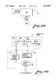
- FIG. 1is a block diagram of the preferred embodiment of the present invention.
- FIG. 2is a block diagram of a serial interface-type network converter.
- FIG. 3is a block diagram of a parallel interface-type network converter.
- FIG. 4is a block diagram of a specialized-type network converter.
- FIGS. 5A and 5Bare a flow chart of the method used for positioning a camera.
- FIGS. 6A and 6Bare an illustration of the operation of the automatic zoom feature of the present invention.
- FIG. 7is a flow chart of the method for controlling the aim point and the zoom operation of the camera.
- FIG. 8is a schematic block diagram of a video unit control node.
- FIG. 9is a schematic block diagram of an audio unit control node.
- FIGS. 10A-10Care illustrations of the relationship between regions.
- FIGS. 11A and 11Bare a flow chart of the camera focusing process.
- FIG. 12Ais an illustration of the preferred embodiment of a camera of the present invention.
- FIG. 12Bis an illustration of the feedback system associated with the camera controls.
- FIG. 13is an illustration of a two-monitor videoconferencing system of the present invention.
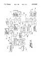
- FIG. 1is a block diagram of the preferred embodiment of the present invention.
- the videoconferencing systemcomprises a controller 10, a plurality of network converters (C) 11A-11K connected to a network 23, a mouse 12, a control panel 13, an audio unit control node 14, a video unit control node 15, a coder-decoder (codec) 16, a camera unit control node 17, a joystick 18, a power supply 19, a video cassette recorder/playback unit (VCR) 20, monitors 21, and a modem 22.
- the video teleconferencing systemalso comprises items which, for the sake of clarity, are not shown in FIG. 1, such as: cameras, pan/tilt and zoom/focus units for the cameras, microphones, speakers, audio cabling, video cabling, and telephone and power wiring.
- Each device 10, 12-22is connected to a converter 11A-11K.
- the convertersare connected, preferably in a daisy-chain (serial) manner, via the network designated generally as 23.
- Converter 11Ais shown as part of controller 10, and converters 11B-11K are shown as being stand alone components which are separate from their respective connected devices 12-22. However, this is merely a preference and any converter 11 may be a stand alone component or may be a part of its associated device.
- the network 23is the LON-based network developed by Echelon, Inc., Palo Alto, Calif. However, other networks, such as Ethernet, may be used.
- Each converter 11contains information which either converts network standard signals on network 23 into control signals for the connected device 10, 12-22, converts control/status signals for the connected device(s) into network standard signals for network 23, or both.
- network controller 11Bwill convert signals from the mouse 12 into network standard control signals which represent the mouse movement, such as left, right, up, down, button 1 depressed, button 1 released, etc.
- Network converter 11Bprovides the same network standard control signals for a particular type of mouse movement regardless of the type of mouse being used.
- network standard control signals from control devicessuch as mouse 12, control panel 13, joystick 18 or codec 16, are sent, via converters 11 and network 23, to controller 10.
- a single convertercan service two or more devices, such as converter 11B servicing mouse 12 and joystick 18, and converter 11I servicing two monitors 21A and 22B.
- converter 11Balso sends information as to whether the activity is associated with the mouse 12 or the joystick 18.
- the controller 10then inspects these network standard control signals to determine the type of action requested by the user and the device which should take the action, generates network standard control signals corresponding to the desired action, and places these signals onto the network 23.
- a converter 11inspects the address of the incoming network standard signals on the network 23 to determine if the data is intended for that converter or its connected device. If so, then the converter 11 will capture the data, which is a network standard control signal representing the desired action, and convert the data into the appropriate type of signal for the connected device.
- converter 11Bconverts the mouse movement signals into network standard control signals indicating, for example, the direction of the movement of the mouse and the status of the buttons on the mouse (depressed, not depressed).
- Converter 11Bthen generates an address for controller 10 and places these network standard signals on network 23.
- Converters 11C-11Kignore these signals because the address indicates that the signals are not for them.
- Converter 11Arecognizes the address as its own, captures these signals, and provides the signals to controller 10.
- Controller 10determines that the network standard control signals signify a mouse movement corresponding to an instruction for the selected camera to pan to the left and, accordingly, generates network standard control signals corresponding to such camera movement. Controller 11 then instructs converter 11A to address these signals to the network converter for pan/tilt unit control node 17 and to place these signals on network 23. Converter 11G recognizes the address as its own (or as intended for its connected pan/tilt device), and captures the network standard signals. Converter 11G then generates control signals appropriate for the type of pan mechanism (not shown) used with the selected camera.
- the network standard signals from the mouse or to the pan/tilt mechanismwill not change. Rather, the network converters 11 will convert the signals from the mouse 12 into network standard signals and will convert the network standard signals into signals appropriate for the pan/tilt mechanism.
- the signals from mouse 12may indicate that mouse 12 is being moved to the left at a certain rate and the appropriate signals provided to the pan motor may be +12 volts or, if the pan motor has a digital controller or interface, the signals provided by converter 11G may be a binary signal such as 101011 or some other code which corresponds to the code and format required to achieve the specified action.
- controller 10may not be required and converters 11 and 11G may be programmed to achieve the desired correspondence between the movement of the mouse 12, the depression of keys on control panel 13, and movement of the pan motor.
- mouse 12is also used to specify functions which do not have a one-to-one correspondence between mouse movement and pan motor action, such as the point-and-click and the draw-and-release operations described below and therefore all network signals are directed to or come from controller 10.
- monitor control node 21is addressed by converter 11I to controller 10 (converter 11A) and then placed on network 23. Controller 10 then inspects the status information to determine if the selected monitor (not shown) is in the proper mode, such as on or off.
- Control panel 13is a conventional videoconferencing system control panel, well known in the art, and provides, via buttons, such functions as pan left, pan right, tilt up, tilt down, mute on/off, zoom in/out, focusing, presettable camera settings, and volume up/down.
- Audio unit control node 14controls the flow of audio signals among the devices which send or receive audio signals, such as microphones, speakers, codec 16, telephone lines, and VCR 20.
- Video unit control node 15controls routing of video signals among the different devices which send or receive video signals such as codec 16, VCR 20, cameras, and monitors 21.
- Codec 16provides conventional codec functions.
- Camera unit control node 17controls the pan, tilt, zoom, and focus of the cameras and provides feedback regarding these parameters.
- Power supply 19provides operating power for the converters 11 and also for the other devices 10, 12-18, 20-22 connected to the system.
- VCR 20is a conventional video cassette recorder/playback device.
- Monitors 21are commercially available monitors and, in the preferred embodiment, are Mitsubishi color televisions, model CS-35EX1, available from Mitsubishi Electronics America, Inc., Cypress, Calif.
- Modem 22is a conventional modem, preferably having a data communications rate of at least 9600 bits per second.
- a typical codec 16has a port for connection to one or more dial-up or dedicated telephone lines.
- codecshave a data port which can also be used for transferring data as well as for setting up the codec. This data port is advantageously used in the present invention to allow a codec 16 to be configured by the controller 10.
- codec 16is a type Visualink 5000, manufactured by NEC America, Inc., Hillsboro, Oreg.
- Controller 10will, via converters 11A and 11F and network 23, instruct codec 16 to dial up or otherwise access the remote codec (the codec at the other videoconferencing location). Codec 16 will then attempt to establish communications with the remote codec. If communications are successfully established the codecs will negotiate what features will be used and then the session may begin. However, if communications cannot be established, such as because the codecs are configured for different protocols, the local codec 16 will report to controller 10 that codec 16 was able to contact the remote codec but was unable to establish communications (handshake) with the remote codec because the remote codec was using a different protocol.
- Controller 10will then, via converters 11A and 11N, instruct modem 22 to dial up the remote modem (the modem for the videoconferencing system at the other location). Once controller-to-controller communications have been established via modem then controller 10 can instruct the remote controller to configure the remote codec for a particular protocol. The remote controller will take action, if necessary, to configure the remote codec to the same protocol. Conversely, controller 10 can receive information from and/or negotiate with the remote controller as to the protocol(s) supported by, or the current configuration of, the remote codec and then configure codec 16 to the same protocol as the remote codec. Then, controller 10 can again instruct codec 16 to establish communications with the remote codec and, as both codecs have now been configured to the same protocol, the codecs can establish communications and negotiate features, and the videoconferencing session can begin.
- controller 10may also communicate with a similarly situated controller at a remote site (not shown) via the data port on codec 16.
- the userusing mouse 12, control panel 13, or joystick 18, may command a particular action to be performed at the remote site, such as panning the remote camera to the left or right, tilting the remote camera up or down, etc.
- the user's actionsare converted into network standard control signals and these signals are sent by converter 11B to controller 10.
- Controller 10determines the action required at the remote site and sends, via network 23 and codec 16, network standard control signals corresponding to the action to the remote controller.
- the remote controllerthen sends, via its own network, the network standard signals to the converter for the remote pan/tilt unit.
- the remote converterthen generates the appropriate instruction for the remote pan/tilt unit control node which, in turn, causes the pan/tilt mechanism for the selected remote camera to perform the action specified by the user at the local site.
- the user at the local sitecan therefore control all of the functions of all the devices at the remote site that the remote user can control at the remote site, even if the remote site has devices available which are not available at the local site.
- some functions at a siteare preferably controlled only by the user at that particular site, such as microphone muting, monitor on/off operation, and speaker volume control settings.
- the present inventionalso provides for system diagnostics.
- camera unit control node 17in addition to receiving instructions from controller 10, also reports the results of an instruction to controller 10.
- Each pan/tilt unithas a position indicator, either as part of the unit or as a retrofit device.
- the position indicatorindicates the current pan position and the current tilt position.
- the camera unit control node 17accepts the position signals from the position indicator and provides these signals to the controller 10.
- Controller 10inspects these signals to determine whether the selected pan/tilt unit is taking the proper action with respect to the control signals. For example, assume that controller 10 has instructed a particular pan/tilt unit to pan in a certain direction at a certain rate but that the pan/tilt unit either does not pan, or pans at a different rate.
- the camera unit control node 17reports the response of the selected pan/tilt unit to controller 10. If the response of the selected pan/tilt unit is improper then controller 10 will cause a report to be generated which alerts the system operator to the problem.
- the reportmay be provided in a number of ways. For example, the presence of the report may be indicated by an icon on the screen of a monitor 21. This alerts the system operator to select the report to ascertain the nature of the problem. Or, the controller 10 may cause a report to be printed, either by a printer (not shown) connected to a printer port on controller 10 or by a printer (not shown) connected as another device on the network 23. The report may also indicate the severity of the problem.
- a slow panis generally not a critical item, but indicates that the pan/tilt unit should be serviced in the near future to prevent the complete failure of and/or damage to the unit.
- a unit which does not pan at allrequires immediate servicing as continued attempts by the user to cause that pan/tilt unit to pan could result in gear damage or motor burnout.
- Modem 22also allows for remote diagnostics and reporting. If the videoconferencing system is, for example, being serviced by a remote party then the remote party can, using a personal computer and a modem, call up modem 22, establish communications with controller 10, and instruct controller 10 to send, via modem 22, the current system diagnostics. Furthermore, controller 10 can be programmed to use modem 22 to call up the remote party, establish communications with the remote computer, and automatically send the current system diagnostics. The programming may specify that the call is to be performed at a certain time of day, such as during off-duty hours, or whenever a serious failure occurs, such as the complete failure of a pan/tilt unit, or both.
- the controller-to-controller communicationsvia either codecs or modems, also allows the controller at one site, such as a remote site, to inform the controller at another site, such as the local site, that a particular device or function is inoperative at the remote site. Then, when the user attempts to use that device or function the local controller will disregard the instructions from the user and inform the user that that device or function is out of service.
- Controller 10in addition to performing system diagnostics, also attempts simple system repairs. For example, if the pan/tilt unit will not pan in one direction, controller 10 will instruct the pan/tilt unit to pan in the other direction so as to attempt to dislodge any cable which may be snagged. If this action is successful and the pan/tilt unit is then operational controller 10 will log the failure and the repair so that the service technician will know to inspect that unit for loose or snagged cables and to service that unit. If the action is not successful then controller 10 will disregard future instructions from the user as to the desired movement of that pan/tilt unit and will not attempt to send further instructions with respect to the failed function. That is, pan instructions will not be sent because the pan function is not operative, but tilt instructions may be sent because that function still operates properly. However, as another option, controller 10 may be programmed to cause operating power to be entirely removed from the failed pan/tilt unit.
- the camera unit control node 17also controls the zoom and focus of the connected cameras (not shown).
- the camerashave a zoom position indicator and a focus position indicator, either as part of the unit or as a retrofit device.
- Controller 10can therefore determine whether a selected camera is operating properly.
- each monitor 21has an on/off indicator, described below, and converter 11I reports the status of each monitor. Controller 10 can therefore determine whether a selected monitor is on or off.
- codec 16performs limited self-diagnostics on its own operation. Controller 10, either in response to an error signal from codec 16, or at periodic intervals, will instruct codec 16 to report its status. Controller 10 can then take the appropriate reporting action, if any is required, and/or switch to another codec (not shown) connected to network 23.
- the LON networkis used because converters 11, in general, draw operating power via the network 23 and do not require a separate source of power nor require power from the connected device. This is advantageous in that the network and the system will continue to function even if a connected device, such as VCR 20 or modem 22, is removed from the network or is powered down.
- a power supply 19is connected to the network 23 and provides operating power for the converters 11.
- Power supply 19also provides operating power, such as 110 VAC or 12 VDC, to each peripheral device. This operating power may be provided via network 23 or provided via separate power cables to each peripheral device.
- Power supply 19provides AC and DC power, as required, to each peripheral device.
- Power supply 19is connected to converter 11K and may therefore be controlled by the user. This allows the user to turn on and turn off selected peripheral devices, as desired, by removing operating power from the device. This provides an additional way of turning off a device if the device is otherwise non-responsive to signals sent via network 23, and also provides a safety factor in that the user can completely remove operating power from a device.
- converter 11Khas an internal timer.
- converter 11Kwill send a "sleep" signal to controller 10. This causes controller 10 to go into a standby mode, thereby conserving power. Converter 11K will also instruct power supply 19 to remove operating power from the peripheral devices. Although converter 11K and power supply 19 are shown as separate devices, it will be appreciated that both functions may be performed by a single device. In an alternative embodiment, power supply 19 is not responsive to signals on network 23 but merely provides operating power for the converters 11. In this embodiment either controller 10 or converter 11K may have the internal timer. In another alternative embodiment, power supply 19 is not used and controller 10 has the internal timer, and also provides operating power for the converters 11 on network 23 via the connection to converter 11A.
- controller 10is a personal computer, such as a COMPAC Prolinea, having a 120 megabyte hard drive, a 4 megabyte random access memory, and a 31/2-inch floppy disk drive. Controller 10 does not need to have a screen or a keyboard because, in the preferred embodiment, a monitor 21 is used as a screen, and mouse 12 and control panel 13 may be used in place of a keyboard. However, if desired, a screen and a keyboard could be connected directly to controller 10.
- a monitor 21is used as a screen
- mouse 12 and control panel 13may be used in place of a keyboard.
- a screen and a keyboardcould be connected directly to controller 10.
- mouse 12, control panel 13, and joystick 18are shown as being connected to converters 11B and 11C by wiring, it will be appreciated that there are commercially available devices 12, 13, and 18 which do not have a wire connection but, instead, communicate by infrared(IR) signals. These devices may also be used with the present invention.
- the appropriate network converter 11would have an IR receiver, would respond to the infrared signals, and would provide the corresponding network standard signals to controller 10.
- Converter 111would then be a specialized purpose converter.
- a specialized purpose converteris described below which transmits IR signals to IR receivers in monitors 21. In this case, the role of transmitter and receiver is reversed, that is, the devices 12, 13, 18 transmit and the converters 11B, 11C receive.
- Converters 11fall into three general classes: serial interface, parallel interface, and specialized purpose.
- a codec 16is a serial interface device and therefore converter 11F would be a serial interface-type converter
- a VCR 20may have a parallel interface and therefore converter 11H would be a parallel interface-type converter.
- monitors 21are of the type which can be remotely controlled by, for example, a handheld infrared remote control.
- Converter 11Iis therefore a specialized type of converter in that it can provide the infrared signals necessary to control the monitors 21 and has the necessary components for monitoring the state of operation of the monitors 21.
- FIG. 2is a block diagram of a serial interface-type network converter 11.
- a serial-type converter 11comprises a network connector 40, a power supply/filtering circuit 41, an RS-485 transceiver 42, a parallel-serial and serial-parallel (P/S-S/P) converter 48, a microprocessor 43, a basic program memory 44, an installed program memory 45, a set-up button 46, a display 47, an RS-232 charge pump/transceiver 50, and a serial port connector 51.
- Connector 40is connected to network 23 and connector 51 is connected to a serial interface device, such as codec 16.
- Power supply/filtering circuit 41draws power from network 23 and provides filtered power to the several circuits of converter 11.
- Transceiver 42provides voltage level, balanced-to-single-sided (unbalanced), and single-sided-to-balanced conversion of the signals between network 23 and P/S-S/P converter 48.
- P/S-S/P converter 48provides parallel-serial and serial-parallel conversion of the signals between transceiver 42 and the microprocessor 43.
- microprocessor 43is a Neuron microprocessor, manufactured by Motorola Semiconductor Products, Phoenix, Ariz. and the P/S-S/P conversion functions of converter 48 are performed by the microprocessor 43.
- Basic program memory 44contains an identification number, such as a serial number, start-up procedures and basic operating instructions for microprocessor 43, such as instructing microprocessor 43 of the port or address of transceivers 42 and 50, button 46 and display 47.
- memory 44is a programmable read only memory (PROM).
- Installed program memory 45contains configuration information and operating instructions as to the conversion required between signals present on network 23 and the corresponding signals to be output via connector 51, and vice versa. Examples of the type of information that may be installed in memory 45 are the voltage polarity and voltage levels required to control the connected peripheral device, the binary codes and format required to control the connected peripheral device, and similar information concerning signals that may be received from the connected peripheral device.
- memory 45comprises both an electrically erasable programmable read only memory (EEPROM) and a random access memory (RAM).
- Button 46is used to initialize (set up) converter 11, as explained in more detail below.
- Display 47is, in the preferred embodiment, a light emitting diode (LED) and is off when microprocessor 43 has been properly set up (configured), and flashes when microprocessor 43 is in the set up mode (not configured).
- controller 10contains, in its memory (not shown), a plurality of programs for the operation of converters 11. There is a separate program for each type of device that may be connected to a converter.
- Converters 11F and 11Jare both serial interface-type converters. However, one is connected to codec 16 and the other is connected to modem 22, and therefore each requires different operating instructions so as to properly interface with the connected device. Therefore, for each type of converter, there is a separate program for each type of device which may be connected to that converter.
- a programwhich may include software, firmware, data, formats, conversion codes, etc., is downloaded from controller 10 to the selected converter 11 so as to properly configure the converter 11 for the type (serial, parallel, specialized) of converter that it is and also for the type of device with which it will be connected.
- Thisprovides flexibility in that if a new type of device is to be connected to the network then a program is written for that type of device and loaded into controller 10. Controller 10 then downloads the program to the converter 11 which is connected to that new type of device. Therefore, in general, a serial interface-type converter can be used with any serial interface device by simply downloading the appropriate serial interface program from controller 10 into that converter 11, and likewise for parallel interface-type devices.
- controller 10can easily support additional devices by using the appropriate generic (serial-type or parallel-type) converters and then causing controller 10 to download the appropriate programs to each of the added converters. This reduces the inventory of different types of converters that the user must have on hand to repair or add to the system.
- memory 45 in a serial-type converter 11is not programmed with the installed program at manufacture, although it could be so programmed if desired. Therefore, when a converter 11 is first installed in the videoconferencing system and power is applied, the converter 11 will not be configured. Furthermore, if the user changes the type of serial device connected to the converter 11, such as disconnecting converter 11 from codec 16 and connecting converter 11 to modem 22, then converter 11 will be improperly configured for the newly connected device. Therefore, the user will press set up button 46, which causes microprocessor 43 to cause display 47 to begin blinking. Also, microprocessor 43 will send its identification number and type to controller 10 along with a network standard signal which advises controller 10 that converter 11 needs to be configured.
- the userwill then go to controller 10 and, preferably using mouse 12, pull down an initial set up menu (not shown).
- the set up menuwill list the last converter 11 which has reported a need to be configured.
- the userwill pull down another menu which lists the types of serial interface devices supported by the videoconferencing system.
- the connected serial deviceOnce the connected serial device is identified by the user controller 10 will download, via network 23, the program necessary to allow converter 11 to interface between network 23 and the connected serial device.
- Microprocessor 43will install this program in the installed program memory 45.
- Microprocessor 43 and memories 44 and 45are shown as separate components for clarity but may be in a single device. If converter 11B has not been previously configured then a mouse, such as mouse 12, may be connected to a mouse control port on controller 10 in order to configure converter 11B. Thereafter, the remaining converters may be configured using either mouse 12 or the mouse connected directly to controller 10.
- FIG. 3is a block diagram of a parallel-interface type network converter 11.
- a parallel-type converter 11is similar to that of a serial-type converter except that, instead of transceiver 50 and connector 51, converter 11 will have an output transceiver 54 and a parallel connector 57.
- Output transceiver 54comprises output drivers 55 and input buffers 56.
- transceiver 54provides isolation between microprocessor 43 and the parallel interface device.
- device 54is preferably configurable by microprocessor 43 to select which pins on connector 57 are output pins and which pins are input pins. Devices which perform, or can be readily connected to perform, the functions of transceiver 54 are well known in the art.
- transceiver 54the functions of transceiver 54 are performed by the indicated Neuron microprocessor 43.
- the operation of a parallel-type converter 11is identical to that of a serial-type converter except that the inputs and outputs on connector 57 are configured for a device which is a parallel interface device, such as VCR 20.
- FIG. 4is a block diagram of a specialized-type network converter, such as converter 11I.
- a specialized converteris useful in cases where the connected device does not have a serial or parallel interface or where that interface is already in use for some other purpose, but where there are also other means of controlling the device, such as by infrared signals or voltage level and/or polarity signals (analog signals).
- Converter 11Iwhich interfaces with monitors 21, is an example of a specialized converter.
- a specialized-type converterhas a connector 40 for connection to the network 23, a power supply/filtering circuit 41, an RS-485 transceiver 42, a microprocessor 43, a basic program memory 44, an installed program memory 45, a set up button 46, and a display 47.
- specialized converter 11has a driver 61, which is capable of driving infrared (IR) LEDs 62A and 62B. Only two IR LEDs are shown, corresponding to two monitors 21, for convenience, but more monitors 21 may be used. Each monitor 21 is, in the preferred embodiment, controllable by the use of infrared signals and has an infrared detector built into the monitor 21.
- IRinfrared
- An IR LEDsuch as 62A
- driver 61which provides the signals to the LED 62A, which emits the infrared signals appropriate to cause monitor 21 to perform a particular action, such as turning on or off, turning the volume up or down if the speaker in monitor 21 is being used, adjusting brightness, contrast, etc.
- a coilsuch as coils 63A and 63B, is attached to each monitor 21.
- a coil 63is used to pick up the magnetic field of the horizontal deflection coils present in a monitor 21.
- Coils 63A and 63Bare connected to amplifier/detectors 64A and 64B, respectively.
- An amplifier/detector 64amplifies the signal provided by a coil 63 and detects (rectifies) the signal.
- the output of each amplifier 64is connected to buffer 65, which is connected to microprocessor 43. Buffer 65 provides any necessary buffering and voltage level shifting between the output of amplifier/detector 64 and microprocessor 43.
- the on/off control signal in many monitors 21is the same signal and the monitor 21 merely toggles between an on state and an off state.
- a coil 63is attached to the monitor 21 to pick up the radiation emitted by the horizontal deflection coil in that monitor 21. If the user sends an instruction to turn on a monitor 21 the microprocessor 43 will inspect the output of buffer 65 to determine if the coil 63 and amplifier/detector 64 associated with that particular monitor 21 are detecting radiation. If radiation is being detected then the monitor is already on and microprocessor 43 will not take any action. However, if monitor 21 is off then radiation will not be detected and, consequently, microprocessor 43 will cause driver 61 to pulse an LED 62 with the code required to toggle the on/off control of that monitor 21. Microprocessor 43 will then check the output from the coil 63 to determine if the operation was successful.
- microprocessor 43If the operation was successful then microprocessor 43 will take no further action. However, if monitor 21 does not turn on then microprocessor 43 will attempt several more times to turn on the monitor 21. If, after several attempts, the monitor 21 is still not on then microprocessor 43 will report the failure to controller 10.
- coils 63are a type 70F103AI, manufactured by J. W. Millen, Collinso Dominguez, Calif.
- the positioning of the coils 63 on the monitors 21is not extremely critical but it is preferred to place the coils 63 in a position to receive the maximum pick up when a monitors 21 is on so that the reliability of the on/off indication is consistently high.
- the basic program memory 44may contain the necessary IR transmit instructions, and so install program memory 45, set-up button 46, and display 47 will not be needed. However, if converter 11 may be used with different types of monitors then the necessary instructions for the several types of monitors may be included in basic program memory 44 or, alternatively, the type of monitor being used may be selected from a pull-down menu at controller 10 and the necessary IR transmit program downloaded from controller 10 in memory 45.
- tests and/or functions shown in the figuresare performed by programs or subroutines which are simultaneously active so that one test and/or function may be performed concurrently with another test and/or function. That is, tests for mouse movement, mouse button depression/release, joystick movement, control panel selections, etc., are performed continuously or may be interrupt driven functions.
- flowchartsare used for clarity of illustrating the operation of the present invention.
- FIGS. 5A and 5Bare a flow chart of the method used for positioning a camera.
- the mouse 12 or the joystick 18may be used to move a pointer within the display presented on a monitor, such as monitor 21A.
- monitor 21AFor convenience, only the operation using mouse 12 will be discussed although it will be appreciated that joystick 18, with control buttons thereon, can be used to accomplish the same result.
- This particular method of positioning the camerais referred to herein as "point-and-click”. This phrase describes the action required by the user to reposition the camera. That is, using mouse 12, the user causes the pointer to be positioned (pointed) over the target of interest and then clicks a button on mouse 12.
- Controller 10then causes the selected camera to be aimed at the selected point so that the selected point is nominally in the center of the screen display seen by the user. This allows the user to quickly and easily designate where a selected camera should be pointing so that the user can conveniently view the desired object(s). It should be noted that this method is useful for both local cameras, that is, cameras which are at the same site as the user, and for remote cameras, that is, cameras which are at the remote site. Therefore, the user can easily adjust the remote camera to point at a desired object. This allows the user to focus a camera on a target of interest without having to instruct the person at the other end to stop whatever he or she is doing and position the camera as desired by the user.
- a starting step 100is shown but it will be appreciated that controller 10 performs many operations and therefore a starting step should be understood to be an entry point into a subroutine, such as a subroutine used for camera positioning.
- decision 101a test is made as to whether any mouse button 12A, 12B is depressed. If so then the user is indicating that some function other than point-and-click camera positioning is to be performed and therefore other functions are tested and/or performed in step 102. If no mouse buttons are depressed then, in decision 103, a test is made for movement of the mouse. If there is no mouse movement then a return is made to decision 101.
- decision 104tests whether the pointer displayed on the screen of monitor 21A is outside the area of the monitor designated for the picture. That is, is the pointer now positioned over a control bar, selection icon, other function symbol, a different picture (picture-within-picture), or a different monitor. If the pointer is outside the picture area then the user is indicating that other functions are to be performed and controller 10 proceeds to step 102 to perform the other functions. If the pointer is within the picture area then decision 105 tests whether a mouse button, such as mouse button 12A, has been clicked. If not then a return is made to decision 101. If so then controller 10 determines in step 106 the amount of pan and tilt required to achieve the user's request.
- a mouse buttonsuch as mouse button 12A
- Step 107tests whether the amount of pan required is greater than the resolution error of the pan mechanism. That is, if the amount of pan required is one degree but the pan mechanism has a resolution error of two degrees, then panning should not be done. If panning is not to be done then decision 108 is executed. Decision 108 tests whether the tilt required is greater than the resolution error of the tilt mechanism. If the tilt required is not greater than the resolution error then a return is made to decision 101 because it has been determined that neither pan nor tilt is required. If, in decision 108, the tilt required is greater than the resolution error then step 112 is executed next.
- step 110the pan rate is determined. Then, in decision 111, a test is made as to whether the tilt is greater than the resolution error. If dot then step 113 is executed next. However, if the tilt is greater than the resolution error then the tilt rate is determined in step 112.
- an undesirable affectmay occur when moving long distances, such as from one preset location to another when the field of view is narrow.
- the field of viewis 6 degrees
- the pan anglewill be 60 degrees. If the pan rate is selected to cause the object to move across the field of view (6 degrees) in time T, then it will take 10 T seconds for the camera to reach its destination. However, if the pan rate is selected to cause the camera to traverse the full distance in T seconds, then the 6 degree field of view will cause objects to fly across the scene in a blur.
- the camerais to pan over a long distance the camera is zoomed out (and focused accordingly) so that the camera has a wide field of view.
- the high speed pan ratewill then allow the movement from start to finish to occur in a timely manner but, because the camera is zoomed out, an object will be reduced in size and will move at an acceptable rate across the display screen.
- the camerais zoomed in (and focused accordingly) as specified by the destination location.
- controller 10determines whether the pan distance is sufficiently large to require zooming out. If not then step 115 is executed. If so then the camera is zoomed out and then step 115 is executed.
- step 115pan, tilt, and/or zoom, as required, are begun.
- Decision 116tests whether the pan/tilt operation has been completed. If not then a return is made to decision 116. If the operation is complete then the zoom and focus are restored in step 117, if necessary, and the process of camera movement is ended in step 118.
- the rate of pan and tiltare determined by considering the desired number of seconds that it should take an object to move from one end of the field of view to the other end of the field of view. In the preferred embodiment, this setting is programmable at controller 10.
- the displayis considered to have a 2 ⁇ 3 aspect ratio (V to H). If it is desired that the object remain within the field of view for, for example, two seconds, and the field of view is, for example, 30 degrees, the pan speed will be set to 15 degrees per second and the tilt speed will be set to 10 degrees per second.
- the camerawill reach the desired position, with respect to both axes, at approximately the same time. This has the desirable effect of making the camera positioning appear smooth. Otherwise, the camera may reach the desired position with respect to one axis first, for example the vertical axis, and then have to continue moving with respect to the other axis until the desired location is achieved, which makes the camera movement appear awkward.
- the point-and-click method of camera controlis a major improvement over existing button methods of camera control.
- the present inventionprovides an alternative form of movement. If this alternative form is selected by the user, such as by using a pull down menu or by pressing on a different mouse button such as button 12B, the camera will dynamically follow the pointer. In this case, if the pointer is moved slowly toward the side of the display controller 10 would cause the camera to slowly pan toward that side.
- controller 10When the pointer is positioned all the way to the side of the display, or at some predetermined border point, controller 10 instructs the pan/tilt unit to move at its maximum speed. Controller 10 automatically zooms out the camera when panning at high speed and automatically zooms in the camera to its original setting when the pointer is no longer at the side of the display and the pan speed is dropped to a slower rate. Of course, the user can adjust the zoom at any time.
- FIGS. 6A and 6Bare an illustration of the operation of the automatic zoom ("draw-and-release") feature of the present invention.
- FIG. 6Ais an illustration of a monitor 21 having a screen 125, which is displaying a person 126 sitting at the end of a table 127. Assume now that the user wishes to focus on the person 126. Using a conventional system the user could adjust the pan and tilt controls and then adjust the zoom and focus controls so as to zoom in on person 126.
- the userwill simply use the mouse 12 to place the pointer at the desired pointer starting point (PSP), depress and hold a predetermined mouse button, such as the left button 12A, and drag the pointer across the area of interest, which causes a rectangular box to begin spreading across the screen, with one corner at the PSP.
- a predetermined mouse buttonsuch as the left button 12A
- PEPpointer ending point
- the userwill release the mouse button. The user has thereby drawn a rectangle around the area of interest and released the mouse button.
- Controller 10will then determine the appropriate pan and tilt for a camera and cause the camera to center its field of view on the center of the rectangle (CR), then cause the camera to zoom in so that rectangle 128 fills, as fully as possible, screen 125, and also cause the camera to refocus, if necessary.
- the resultant displayis seen in FIG. 6B, which illustrates that the camera has been repositioned so that CR is now in the middle of the display (MD). Therefore, by the simple tasks of positioning the pointer in one comer of the desired scene, depressing a mouse button, dragging the mouse to draw a rectangle, and releasing the mouse button, the user has caused the selected picture area to be expanded to fill the display 125.
- the use of point, click, drag, and release techniques to draw a box, such as box 128,are, in general, well known in the personal computer field.
- FIG. 7is a flow chart of the method for controlling the aim point and the zoom operation of the camera.
- controller 10tests, at decision 131 whether the appropriate mouse button has been depressed. If not then, in step 132, controller 10 tests for and/or performs other functions. If the mouse button has been depressed then, in step 133, controller 10 records the initial pointer position PSP. Then, in decision 134, controller 10 tests whether the mouse button has been released. If the mouse button has not been released then the user has not completed drawing the desired rectangle 128. Once the mouse button is released then the user has completed drawing rectangle 128 and has therefore designated the area of interest. Controller 10 therefore proceeds to step 135 and performs the following operations. First, the final pointer position PEP is recorded.
- Controller 10calculates the difference between the midpoint CR of rectangle 128 and the midpoint MD of display 125. These steps determine the pan and tilt required to center the desired picture on screen 125 and, although performed automatically, are analogous to the user moving the pointer to position CR and then clicking on the mouse, as in the procedure described with respect to FIG. 5. Controller 10 then performs steps 106 through 117 of FIG. 5 except that the "No" output of decision 108 does not return to step 101 but moves to substep 5 of step 135.
- controller 10has caused the camera to pan and tilt so as to place the center CR of rectangle 128 at the midpoint MD of display 125.
- controller 10must still determine how much zoom is required to satisfy the request of the user. Therefore, controller 10 determines the X-axis movement XM of the pointer and the Y-axis movement YM of the pointer. Controller 10 then adds the X-axis movement and the Y-axis movement to obtain the total movement of the pointer. Controller 10 then determines the ratio of the total movement (XM+YM) to the total size (XD+YD) of the screen 125 of monitor 21.
- Controller 10determines a new field of view by multiplying the above ratio times the current field of view. It will be appreciated that the current field of view is information which may be obtained from the zoom mechanism on the camera. Controller 10 then causes the camera to zoom to the new field of view or, if the new field of view is less than the minimum field of view supported by that camera, to zoom to the minimum field of view supported. Controller 10 then instructs the camera to focus, either by an auto focus process or by a memory process such as described below, and then the procedure ends.
- the rectangle 128 illustrated in connection with FIG. 6Ahas XM and YM proportions such that zooming in will cause rectangle 128 to nicely fill screen 125.
- the usermay not always draw such a well proportioned rectangle.
- the usermay draw a rectangle which is very wide and has minimal height or is very tall but has minimal width.
- an alternative processmust be followed.
- One possible alternative approachis to expand rectangle 128 so that the larger of XM and YM is used to determine the zoom required.
- This approachwill display to the user all of the area encompassed by rectangle 128 as well as some picture area outside of rectangle 128, as necessary to fill up screen 125.
- the smaller of XM and YMis used to determine the amount of zoom required. In this case the smaller measurement is expanded to fill up screen 125 and some of the area of rectangle 128 encompassed by the larger dimension of rectangle 128 will exceeds the limits of screen 125 and therefore will not be shown to the user.
- FIG. 8is a schematic block diagram of a video unit control node 15.
- video unit control 15is connected to three cameras 150A-150C, three monitors 21A-21C, and a VCR 20. It should be understood that the number of cameras, monitors and VCRs is a design choice and is limited only by the video switching capability of node 15, which is primarily determined by cost considerations.
- Video unit control node 15selectively routes video signals from cameras 150, VCR 20, codec 16 and the auxiliary input, to monitors 21, codec 16, VCR 20 and the auxiliary output.
- codec 16has a motion input and a motion output, for scenes which frequently change, and a graphics input and a graphics output for scenes which infrequently change, such as slides and graphs.
- Video unit control node 15comprises a plurality of video input buffers 151 designated generally as 151, which are connected to the inputs of an 8 ⁇ 8 video switch matrix 152, which is connected to a plurality of output buffers designated generally as 153, a control logic 154, a video overlay device 155, a sync generator input lock signal buffer 160, a plurality of sync separators 161A-161C, a sync generator and phase locked loop (PLL) circuit 162, and a black burst output distribution amplifier 164.
- Buffers 151which also perform DC restoration to the input signal, and buffers 153 buffer the incoming and outgoing video signals in a conventional manner.
- switch matrix 152switches the input signals from cameras 150, VCR 20, codec 16, the video overlay circuit 155, and the auxiliary input to the desired destination device, such as monitors 21, codec 16, VCR 20, and the video overlay circuit 155.
- Control logic 154is connected between converter 11E and switch matrix 152. As will be recalled from a reading of the operation of the system in conjunction with FIG. 1, converter 11E extracts signals from network 23 which are intended for video control node 15 and converts the signals into the proper format for control node 15. Control logic 154 accepts the signals from converter 11E and sends corresponding control signals to switch matrix 152, sync generator and PLL circuit 160, and video overlay circuit 155.
- Sync generator input lock signal buffer 160has an input connected to a Genlock input signal, and an output connected to a sync separator 161A.
- Sync separator 161Ain a well known manner, recovers and separates the vertical synchronization signals from the horizontal synchronization signals.
- the output of buffer 160 and the output of sync separator 161Aare connected to inputs of sync generator and PLL circuit 162.
- Circuit 162provides a black burst output which is synchronized to the selected input signal. For NTSC signals the output of buffer 160 is used as the sync source, for PAL signals the output of sync separator 161A is used as the sync source.
- Control logic 154directs circuit 162 as to which input signal should be used for synchronization.
- buffers 151C and 151Dare connected to the inputs of sync separator circuits 161B and 161 C, respectively.
- the outputs of circuits 161B and 161Care connected back to inputs of buffers 151C and 151D, respectively, so that DC restoration is performed based upon the actual input signal.
- the outputs of buffers 151 A, 151 B, and 151E-151Hcould be provided to sync separator circuits, and the outputs of the sync separation circuits routed back to their respective buffers.
- control logic 154provides a sync signal to these buffers for DC restoration.
- the sync signal provided by control logic 154is preferably the sync signal provided by sync generator and PLL circuit 162.
- Buffers 151 A, 151 B, and 151E-151Hare preferably used as inputs from devices, such as cameras, which can be synchronized to an external source.
- Buffers 151C and 151Dare preferably used as inputs from devices, such as VCR's, which typically cannot be synchronized to an external source. Therefore, for devices which can be synchronized, DC restoration is performed based upon a master (Genlock) sync signal and, for devices which cannot be synchronized, DC restoration is performed based upon the sync signal from that device.
- sync generator and PLL circuit 162is connected to an input of control logic 154. This allows control logic 154 to determine the start of a video frame or the start of a line so that video switching occurs at the proper place in a picture. Also, some codecs require information as to the vertical interval within which switching is to occur and control logic 154 uses the signal from sync circuit 162 to provide this information as well.
- the output of circuit 162is connected to the input of a distribution amplifier 164 which provides several outputs G1-G4, which are black burst generator lock outputs. These outputs are used to synchronize cameras 150 so that the pictures from all cameras 150 are in sync.
- Video overlay circuit 155is used to provide special video effects such as picture within picture, and superimposed graphics and icons.
- Video overlay circuit 155may be part of control node 15, part of controller 10, or an independent device.
- the auxiliary inputis used to provide graphical user interface (GUI) information such as video icons, control "buttons” on the monitor display, control borders and pointers, etc.
- GUIgraphical user interface
- this informationis generated by controller 10.
- Methods of generating GUI informationare well known to those of ordinary skill in the art.
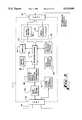
- FIG. 9is a schematic block diagram of an audio unit control node 14.
- Control node 14selectively routes audio signals from various sources to various destinations.
- audio inputsare from an auxiliary input, left and right channel inputs from VCR 20, microphones 174A-174D, a telephone connection, and the audio output of codec 16.
- Destinations for audio signalsare, again by way of example, the record input of VCR 20, a telephone connection, and the audio input of codec 16. Any input audio signal may be routed to any desired destination and, likewise, any destination may receive any selected audio input signal.
- All input and all output signalsare buffered, either by a plurality of buffers/amplifiers designated generally as 173 or a mixing circuit 172.
- the auxiliary input, the TELCO input, and the inputs from microphones 174A-174Dare buffered by buffers/amplifiers 173A-173C, respectively.
- the input from codec 16is buffered by buffer/amplifier 173E.
- the inputs from VCR 20are buffered by mixer 172A.
- the auxiliary input, the VCR 20 inputs, the TELCO input, the microphones 174A-174D inputs, and the codec 16 audio outputare each passed through a muting circuit 170A-170E, respectively, and also through a gain control circuit 171A-171H, respectively.
- the auxiliary input, VCR input, and TELCO inputare then provided to a plurality of mixers designated generally as 172C.
- Mixers 172Ccontain separate mixers for the output to VCR 20, the output to the TELCO, and the output to the audio input of codec 16.
- the inputs from microphones 174are routed to a digital signal processing echo canceller 176.
- the output of echo canceller 176is then routed to the mixers 172C.
- the outputs of three of the mixers of 172Care routed through gain control circuits 171I-171K and buffers/amplifiers 173E before being provided to VCR 20, the TELCO connection, and the audio input of codec 16.
- the audio output from codec 16is routed through a gain control circuit 171H, a mute control circuit 170E, and then to the mixers 172C.
- the output of the fourth mixer of mixers 172Cis routed to the received input of echo canceller 176.
- the received output of echo canceller 176is routed through mute circuit 170F, gain control circuit 171L, and amplifier 173D, before being routed to speaker 175.
- a mute circuit 170comprises, as shown by mute circuit 170A, an analog switch.
- the mute circuits 170are controlled by control logic 177.
- gain control circuits 171, such as gain control 171Aare digitally controlled gain circuits, and are controlled by control logic 177.
- the usercan use mouse 12 to pull down a menu and select a particular input or output device, and then select the gain or muting desired for that particular device.
- the signals from mouse 12are provided by converter 11B to controller 10.
- Controller 10interprets the mouse signals to determine the action requested by the user and, in this case, sends appropriate gain and mute signals to converter 11D.
- Converter 11Dextracts this information from network 11 and sends the appropriate control signals to control logic 177 which, in turn, supplies the appropriate signals to the gain circuits 171 and the mute circuits 170.
- echo canceller 176is an echo cancellation card manufactured by Gentner Communications Corporation, Salt Lake City, Utah. Echoes are typically caused by feedback between a speaker 175 and microphones 174 in a room, and is made more noticeable and distracting by the time delay caused by codec 16 and the additional delay which occurs when the signal is transmitted via satellite.
- the present inventionallows the selection of the camera focus to be controlled by the position of the camera.
- This featureestablishes a database of the room layout and, when the user clicks and/or zooms in on a region the database is consulted to determine the focus settings and the database focus setting is automatically applied to the camera. If the selected objected is slightly out of focus the user will then adjust the focus setting manually. When the user manually adjusts the focus setting the region of the object and/or the appropriate focus setting are added to the database.
- the pan position, tilt position, and field of view anglemay vary slightly from time to time, even though the user is designating the same object.
- the present inventionuses regions, rather than pixels, to determine if the user has selected the same target.
- the databasetherefore consists of a tree of regions.
- a regionis defined as a viewing area seen by a camera and is identified by a polar coordinate system which specifies a pan position, a tilt position, and a camera field of view angle.
- FIGS. 10A-10Care illustrations of the relationship between regions. Two regions are considered to match, or be the same region, if the intersection of the regions contains a certain percentage of each region, as shown in FIG. 10A. In the preferred embodiment, this percentage is programmable and the default setting is 80%.
- a parent regionis a region which completely encompasses another region, as shown in FIG. 10B.
- a parent regionmay be encompassed within another, larger region, and therefore one parent region may be the child of another parent region, as shown in FIG. 10C.
- a master parent regionwhich is a parent to all regions, and is the default focus setting. There is no fixed limit on the number of regions that may be stored in the database.
- FIGS. 10A-10Cillustrate the relationship between fields.
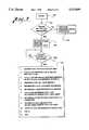
- FIGS. 11A and 11Bare a flow chart of the camera focusing process of the present invention.
- FIG. 11Ais entered whenever there is a change in the pan, tilt, zoom or focus settings of the camera.
- controller 10determines the polar region based upon the pan position, the tilt position, and the field of view angle (zoom setting).
- decision 202a determination is made as to whether the polar region is in the database. If so then in step 203 the focus setting is obtained from the matching polar region in the database and then step 205 is executed. If the polar region is not in the database then, in step 204, the focus setting is obtained for a parent region in the database and the step 205 is executed.
- step 205controller 10 sends signals to converter 11G and control node 17 to adjust the focus of the selected camera. Also, the start time for that focus setting is recorded. This start time is used in step 215 below.
- Decision 206determines whether a new region has been selected, such as by point and click, draw-and-release, manual controls, etc. If so then a return is made to step 201. If not then decision 207 tests whether the user has adjusted the focus since it was set in step 205.
- controller 10sends signals which cause the focus to be adjusted according to the user's instructions and records the focus setting start time.
- controller 10determines whether the current polar region is in the database. If so then controller 10 adjusts the focus setting in the database to correspond to the focus setting actually selected by the user and then returns to decision 206. By this process the focus for a particular polar region is made to conform to the user's particular desires. If the polar region is not in the database then decision 213 tests whether the database is full. If not then controller 10 adds the new polar region and the focus settings to the database and returns to decision 206.
- controller 10searches the database for the least important region and discards that region.
- the least recently used regionis deemed to be the least important region and is discarded.
- controller 10adds the new region and focus setting to the database in step 214.
- the camerais automatically focused on the target selected by the user and, if the selected focus setting is unsatisfactory to the user and the user adjusts the focus setting then the user's selected focus setting is stored for use and is used the next time that the user selects that region.
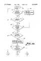
- FIG. 12Ais an illustration of the preferred embodiment of a camera 150 of the present invention.
- Camera 150has a camera body 235, a focusing lens system 230, a zoom/field of view lens system 231, a panning system 232, a tilt system 233, and a camera base 234.
- the design of focusing systems, zoom systems, panning systems, and tilt systems, and cameras themselves,are well known in the art.
- the systemsprovide feedback to controller 10 so that controller 10 can evaluate the response of the system to the instruction sent.
- FIG. 12Bis an illustration of the feedback system associated with the camera controls: systems 230-233, and control node 17.
- a feedback unitwhich is part of systems 230-233, comprises a drive motor 240, a drive shaft 241, a position sensing means 242, and a drive train 243.
- Position sensing means 242may be a variable resistor, a potentiometer, a digital shaft position encoder, etc.
- Drive train 243drives the appropriate focusing, zooming, panning or tilting function.
- Systems 230-233are connected to camera unit control node 17.
- Control node 17comprises control logic 250, a motor power supply 251, and a position-to-digital converter 252. Assume that the user indicates that a selected camera should pan to the left.
- Controller 10will send the appropriate instructions to converter 11G which, in turn, will transfer the instructions to control logic 250 of control node 17.
- Control logic 250will, in turn, cause motor power supply 251 to apply the appropriate voltage to motor 240 to cause motor 240 to turn in the direction which, via drive shaft 241 and drive train 243, causes camera 150 to pan to the left.
- the position-to-digital converter 252converts the change in resistance to digital signals and provides these digital signals to control logic 250.
- control logic 250may close the loop and control motor power supply 251 so as to achieve the pan position specified by controller 10.
- control logic 250sends the current pan position back to controller 10 and controller 10 determines whether the camera 150 has reached the desired position.
- control of motor 240may be effected by the voltage, the pulse width, and/or the polarity of the voltage provided by motor power supply 251, which is controlled by control logic 250.
- Position-to-digital converter 252may directly measure the resistance of a potentiometer in position sensing means 242, may apply a voltage across a potentiometer in position sensing means 242 and measure the output voltage from the potentiometer, or use other means, such as digital shaft position encoding techniques.
- the means of sensing the positionis not critical but should be accurate enough to provide the degree of control necessary to satisfy the user. In the preferred embodiment, a pan position resolution of 0.1 degrees, a tilt position resolution of 0.1 degrees, and a field of view resolution of 0.03 degrees is used.
- the position sensing mechanism 242may be a factory installed part of a system 230-233 or may be a retrofit.
- a camera 150is a Hitachi CCD color camera model KB-C550, manufactured by Hitachi Denshi America, Woodbury, N.Y., and the lens is a Rainbow Automatic Iris electrically driven zoom lens model H6XSMEA-II, manufactured by International Space Optics, Huntington Beach, Calif.
- FIG. 1illustrates only a single camera unit control node 17. However, in the preferred embodiment, there is a separate camera unit control node 17 and a separate converter 11G associated with each camera so that a camera 150 may be attached or removed from the system by connecting and disconnecting a minimum number of wires and cables.
- FIG. 12Billustrates a separate motor power supply 251, position-to-digital converter 252, and control logic 250 for each system 230-233, the present invention is not so limited. If the motors 240 for the different systems 230-233 are of a similar type then a single motor power supply 251 may be used to control all the motors.
- Control logic 250selects the appropriate position sensing means 242 in accordance with the motor 240 of the system 230 that is being driven and needs to be monitored. In this manner, a single control logic circuit 250, motor power supply 251, and position-to-digital converter 252, combined with a multiplexer (not shown), may be employed to service two or more systems 230-233.
- FIG. 13is an illustration of a two-monitor videoconferencing system of the present invention.
- monitors 21Awhich depicts the scene seen by the local camera
- monitor 21Bwhich depicts the scene seen by the remote camera.
- the local camerais showing a desk 300 with two persons 301 and 302, one of which is typically the user.
- Monitor 21Bshows the remote scene which has a person 304 sitting at a desk or table 303.
- Monitor 21Aalso shows a control bar 270. It will be noted that person 304 is not centered in the display on monitor 21B but that the user wishes person 304 to be centered.
- the userwill use mouse 12 to move cursor 280 to control bar 270 and pull down a camera selection menu 271.
- the menuwill pull down by simply moving the cursor over the appropriate position on the control bar and, in another embodiment, the menu will be pulled down if the user positions the pointer over the appropriate position on the control bar and depresses or clicks a button 12A, 12B on mouse 12.
- Methods for pulling down menusare well known in the personal computer field.
- Camera menu 271lists the available cameras such as a local camera, a remote camera, and a graphics camera. In this case the user wishes to select the remote camera so the user will click on the appropriate spot 272 of menu 271 to select the remote camera. This will cause a second menu 273 to pull down listing the functions that can be performed with that camera, such as pan left/right, tilt up/down, zoom in/out, and focus.
- the userwishes to move person 304 to the center of monitor 21B and decides to first pan the camera to center 304.
- the userwill therefore select the panning function 274.
- Thiswill cause a pan control icon 275 to appear on monitor 21B.
- Icon 275shows arrows to allow the user to specify movement of the camera to the right 276 or to the left 277.
- the userwill therefore position pointer 280 over the appropriate arrow and click and hold a mouse button 12A or 12B until the desired position of person 304 has been achieved.
- the usercan go back to menu 273 to select tilt and adjust the tilt position as desired, as well as the zoom and focus.
- the usercould simply use point-and-click technique described above.
- control bar 270 and menus 271 and 273are show in monitor 21A and the icon 275 is shown in monitor 21B it will be appreciated that this is merely a design choice and that the control bar, menus, and icons may be displayed on either monitor and, if desired, can be moved, using control bar 270, from one monitor to the other.
- Mouse 12is preferably used to move pointer 280 between the displays of monitors 21A and 21B. The movement of a cursor or pointer between screens is well known in the personal computer field.
- controller 10also supports operation with picture-within-picture, split-screen, and four-quadrant picture operation. In these cases controller 10 controls, and therefore knows, the switching point between one picture and the next and therefore is able to determine whether the pointer is over a scene controlled by a first camera, a second camera, or even a remote camera.
- Monitor 21Billustrates a picture 281 within the broader picture illustrated. In this illustration, picture 281 is a view of a graph 282. The user could therefore position cursor 280 over picture 281 and controller 10 would know that the subsequent user actions were directed to picture 281 and not directed to the larger picture depicting user 304. If the picture 281 were being generated by a remote camera then controller 10 would send network standard signals corresponding to the desired action to the remote controller, which would cause the remote camera to take the desired action.
- the source of the picture 281may be any camera which is selectable.
- the video unit control node 15is programmed by controller 10 to dynamically connect the appropriate video signals between the appropriate devices so that picture-within-picture and other types of pictures may be obtained. Methods for achieving various multiple picture presentations are well known in the television broadcasting field.
Landscapes
- Engineering & Computer Science (AREA)
- Multimedia (AREA)
- Signal Processing (AREA)
- Closed-Circuit Television Systems (AREA)
- Two-Way Televisions, Distribution Of Moving Picture Or The Like (AREA)
- Studio Devices (AREA)
Abstract
Description
Claims (2)
Priority Applications (1)
| Application Number | Priority Date | Filing Date | Title |
|---|---|---|---|
| US08/373,415US5515099A (en) | 1993-10-20 | 1995-01-17 | Video conferencing system controlled by menu and pointer |
Applications Claiming Priority (2)
| Application Number | Priority Date | Filing Date | Title |
|---|---|---|---|
| US13964593A | 1993-10-20 | 1993-10-20 | |
| US08/373,415US5515099A (en) | 1993-10-20 | 1995-01-17 | Video conferencing system controlled by menu and pointer |
Related Parent Applications (1)
| Application Number | Title | Priority Date | Filing Date |
|---|---|---|---|
| US13964593ADivision | 1993-10-20 | 1993-10-20 |
Publications (1)
| Publication Number | Publication Date |
|---|---|
| US5515099Atrue US5515099A (en) | 1996-05-07 |
Family
ID=22487635
Family Applications (7)
| Application Number | Title | Priority Date | Filing Date |
|---|---|---|---|
| US08/373,415Expired - LifetimeUS5515099A (en) | 1993-10-20 | 1995-01-17 | Video conferencing system controlled by menu and pointer |
| US08/373,417Expired - LifetimeUS5583565A (en) | 1993-10-20 | 1995-01-17 | Method for automatically adjusting the pan and tilt of a video conferencing system camera |
| US08/373,411Expired - LifetimeUS5528289A (en) | 1993-10-20 | 1995-01-17 | Method for automatically adjusting a videoconferencing system camera to center an object |
| US08/373,657Expired - LifetimeUS5526037A (en) | 1993-10-20 | 1995-01-17 | Method for remotely controlling a peripheral device in a videoconferencing system |
| US08/373,868Expired - LifetimeUS5568183A (en) | 1993-10-20 | 1995-01-17 | Network videoconferencing system |
| US08/373,655Expired - LifetimeUS5598209A (en) | 1993-10-20 | 1995-01-17 | Method for automatically adjusting a video conferencing system camera |
| US08/373,412Expired - Fee RelatedUS5589878A (en) | 1993-10-20 | 1995-01-17 | Method of determining an error in a video conferencing system camera |
Family Applications After (6)
| Application Number | Title | Priority Date | Filing Date |
|---|---|---|---|
| US08/373,417Expired - LifetimeUS5583565A (en) | 1993-10-20 | 1995-01-17 | Method for automatically adjusting the pan and tilt of a video conferencing system camera |
| US08/373,411Expired - LifetimeUS5528289A (en) | 1993-10-20 | 1995-01-17 | Method for automatically adjusting a videoconferencing system camera to center an object |
| US08/373,657Expired - LifetimeUS5526037A (en) | 1993-10-20 | 1995-01-17 | Method for remotely controlling a peripheral device in a videoconferencing system |
| US08/373,868Expired - LifetimeUS5568183A (en) | 1993-10-20 | 1995-01-17 | Network videoconferencing system |
| US08/373,655Expired - LifetimeUS5598209A (en) | 1993-10-20 | 1995-01-17 | Method for automatically adjusting a video conferencing system camera |
| US08/373,412Expired - Fee RelatedUS5589878A (en) | 1993-10-20 | 1995-01-17 | Method of determining an error in a video conferencing system camera |
Country Status (8)
| Country | Link |
|---|---|
| US (7) | US5515099A (en) |
| EP (1) | EP0724809A1 (en) |
| JP (1) | JPH09506217A (en) |
| CN (1) | CN1135823A (en) |
| AU (1) | AU7921094A (en) |
| CA (1) | CA2174336A1 (en) |
| SG (1) | SG67927A1 (en) |
| WO (1) | WO1995011566A1 (en) |
Cited By (75)
| Publication number | Priority date | Publication date | Assignee | Title |
|---|---|---|---|---|
| US5706049A (en)* | 1995-11-30 | 1998-01-06 | Eastman Kodak Company | Camera that records an active image area identifier with an image |
| US5745161A (en)* | 1993-08-30 | 1998-04-28 | Canon Kabushiki Kaisha | Video conference system |
| US5841992A (en)* | 1996-03-25 | 1998-11-24 | Snap-On Tools Company | Network-to-serial device intelligent converter |
| WO1999012349A1 (en)* | 1997-09-04 | 1999-03-11 | Discovery Communications, Inc. | Apparatus for video access and control over computer network, including image correction |
| US5970162A (en)* | 1994-06-03 | 1999-10-19 | Canon Kabushiki Kaisha | Image input system having image pickup device capable of mirror-direction panning |
| US6112083A (en)* | 1996-03-27 | 2000-08-29 | Amsc Subsidiary Corporation | Full service dispatcher for satellite trunked radio service system |
| US6122005A (en)* | 1995-04-14 | 2000-09-19 | Canon Kabushiki Kaisha | Camera control system having list of camera names updated in accordance with frequency of use and other ease of use features |
| WO2000076221A1 (en)* | 1999-06-07 | 2000-12-14 | Iviewit Holdings, Inc. | System and method for video playback over a network |
| US6208378B1 (en)* | 1998-02-23 | 2001-03-27 | Netergy Networks | Video arrangement with remote activation of appliances and remote playback of locally captured video data |
| WO2001045406A1 (en)* | 1999-12-17 | 2001-06-21 | Telum (Canada) Inc. | Network-based talk show system |
| US6339842B1 (en)* | 1998-06-10 | 2002-01-15 | Dennis Sunga Fernandez | Digital television with subscriber conference overlay |
| US6346962B1 (en) | 1998-02-27 | 2002-02-12 | International Business Machines Corporation | Control of video conferencing system with pointing device |
| US20020018124A1 (en)* | 2000-07-26 | 2002-02-14 | Mottur Peter A. | Methods and systems for networked camera control |
| US6397275B1 (en) | 1994-09-07 | 2002-05-28 | Viseon, Inc. | Peripheral video conferencing system |
| US6515689B1 (en)* | 1998-07-10 | 2003-02-04 | Fuji Photo Optical Co., Ltd. | Control apparatus |
| US20030025812A1 (en)* | 2001-07-10 | 2003-02-06 | Slatter David Neil | Intelligent feature selection and pan zoom control |
| US20030093430A1 (en)* | 2000-07-26 | 2003-05-15 | Mottur Peter A. | Methods and systems to control access to network devices |
| US20030174202A1 (en)* | 2000-01-13 | 2003-09-18 | Noam Eshkoli | Method and system for controlling multimedia video communication |
| US6665006B1 (en)* | 1993-09-20 | 2003-12-16 | Canon Kabushiki Kaisha | Video system for use with video telephone and video conferencing |
| US20040001148A1 (en)* | 2002-06-26 | 2004-01-01 | Fuji Photo Film Co., Ltd. | Image data processing method, portable terminal apparatus, and computer program |
| US20040010804A1 (en)* | 1996-09-04 | 2004-01-15 | Hendricks John S. | Apparatus for video access and control over computer network, including image correction |
| FR2843516A1 (en)* | 2002-08-12 | 2004-02-13 | France Telecom | Multimedia file real time video conference transmission having files implanted audio video open channel communication without breaking communication |
| US20040070616A1 (en)* | 2002-06-02 | 2004-04-15 | Hildebrandt Peter W. | Electronic whiteboard |
| US20040155958A1 (en)* | 2003-02-10 | 2004-08-12 | Mi-Suen Lee | User assisted customization of automated video surveillance systems |
| US20040163118A1 (en)* | 2000-07-26 | 2004-08-19 | Mottur Peter A. | Systems and methods for controlling devices over a network |
| US20040165079A1 (en)* | 2003-02-25 | 2004-08-26 | Noboru Suzuki | Image-taking control apparatus |
| US20040189802A1 (en)* | 2001-07-27 | 2004-09-30 | Mark Flannery | Control system for allowing an operator to proportionally control a work piece |
| US20050039146A1 (en)* | 1998-02-17 | 2005-02-17 | Microsoft Corporation | Managing position and size for a desktop component |
| US20050099496A1 (en)* | 1996-01-30 | 2005-05-12 | Canon Kabushiki Kaisha | Camera control system |
| EP1468559A4 (en)* | 2002-01-16 | 2005-07-27 | Polycom Inc | METHOD AND SYSTEM FOR CONTROLLING MULTIMEDIA VIDEO COMMUNICATION |
| US20050200717A1 (en)* | 2001-02-23 | 2005-09-15 | Canon Kabushiki Kaisha | Imaging apparatus controller and control method thereof, image processing apparatus and method thereof, and program code and storage medium |
| US20050271220A1 (en)* | 2004-06-02 | 2005-12-08 | Bathurst Tracy A | Virtual microphones in electronic conferencing systems |
| US20050286698A1 (en)* | 2004-06-02 | 2005-12-29 | Bathurst Tracy A | Multi-pod conference systems |
| US20050286696A1 (en)* | 2004-06-02 | 2005-12-29 | Bathurst Tracy A | Systems and methods for managing the gating of microphones in a multi-pod conference system |
| US20050286697A1 (en)* | 2004-06-02 | 2005-12-29 | Tracy Bathurst | Common control of an electronic multi-pod conferencing system |
| US20060012671A1 (en)* | 2004-07-16 | 2006-01-19 | Alain Nimri | Natural pan tilt zoom camera motion to preset camera positions |
| US20060023644A1 (en)* | 2000-03-24 | 2006-02-02 | Margalla Communications, Inc. | Multiple subscriber videoconferencing system |
| US20060082655A1 (en)* | 2004-10-15 | 2006-04-20 | Vanderwilt Patrick D | High definition pan tilt zoom camera with embedded microphones and thin cable for data and power |
| US20060088308A1 (en)* | 2004-10-15 | 2006-04-27 | Kenoyer Michael L | Camera support mechanism |
| US20060093151A1 (en)* | 2004-10-15 | 2006-05-04 | Kenoyer Michael L | Battery operated speakerphone |
| US20060104633A1 (en)* | 2004-10-15 | 2006-05-18 | Kenoyer Michael L | High definition camera pan tilt mechanism |
| US20060104458A1 (en)* | 2004-10-15 | 2006-05-18 | Kenoyer Michael L | Video and audio conferencing system with spatial audio |
| US20060227963A1 (en)* | 2005-04-07 | 2006-10-12 | Ascalade Communications Inc. | Wireless multi-unit conference phone |
| US20060232550A1 (en)* | 2005-04-15 | 2006-10-19 | Buckner Nathan C | Integrated mouse in remote control |
| US20060259552A1 (en)* | 2005-05-02 | 2006-11-16 | Mock Wayne E | Live video icons for signal selection in a videoconferencing system |
| US20060269278A1 (en)* | 2004-10-15 | 2006-11-30 | Kenoyer Michael L | Coordinated camera pan tilt mechanism |
| US7161624B1 (en)* | 1999-04-16 | 2007-01-09 | Fujinon Corporation | Remote control pan head system |
| US20070016868A1 (en)* | 2005-06-30 | 2007-01-18 | Nokia Corporation | Method and a device for managing digital media files |
| US20070171275A1 (en)* | 2006-01-24 | 2007-07-26 | Kenoyer Michael L | Three Dimensional Videoconferencing |
| US20070188599A1 (en)* | 2006-01-24 | 2007-08-16 | Kenoyer Michael L | Speech to Text Conversion in a Videoconference |
| US20070188596A1 (en)* | 2006-01-24 | 2007-08-16 | Kenoyer Michael L | Sharing Participant Information in a Videoconference |
| US20070231631A1 (en)* | 2006-04-03 | 2007-10-04 | Bloom Energy Corporation | Hybrid reformer for fuel flexibility |
| US20080030611A1 (en)* | 2006-08-01 | 2008-02-07 | Jenkins Michael V | Dual Sensor Video Camera |
| US7355621B1 (en) | 1998-06-10 | 2008-04-08 | Fernandez Dennis S | Digital television with subscriber conference overlay |
| CN100425072C (en)* | 2004-07-27 | 2008-10-08 | 索尼株式会社 | Information processing device, information processing method |
| CN100433828C (en)* | 2004-07-27 | 2008-11-12 | 索尼株式会社 | Information-processing apparatus, information-processing methods, recording mediums, and programs |
| US20080316297A1 (en)* | 2007-06-22 | 2008-12-25 | King Keith C | Video Conferencing Device which Performs Multi-way Conferencing |
| USD589996S1 (en) | 2008-02-07 | 2009-04-07 | Lifesize Communications, Inc. | Flat mounted camera |
| USD590000S1 (en) | 2008-02-07 | 2009-04-07 | Lifesize Communications, Inc. | Camera stand |
| USD589995S1 (en) | 2008-02-07 | 2009-04-07 | Lifesize Communications, Inc. | Mountable camera |
| US20090102919A1 (en)* | 2007-12-31 | 2009-04-23 | Zamierowski David S | Audio-video system and method for telecommunications |
| US20100110160A1 (en)* | 2008-10-30 | 2010-05-06 | Brandt Matthew K | Videoconferencing Community with Live Images |
| US20100225737A1 (en)* | 2009-03-04 | 2010-09-09 | King Keith C | Videoconferencing Endpoint Extension |
| US20100225736A1 (en)* | 2009-03-04 | 2010-09-09 | King Keith C | Virtual Distributed Multipoint Control Unit |
| US20100328467A1 (en)* | 2009-06-24 | 2010-12-30 | Sony Corporation | Movable-mechanical-section controlling device, method of controlling movable mechanical section, and program |
| US20110115876A1 (en)* | 2009-11-16 | 2011-05-19 | Gautam Khot | Determining a Videoconference Layout Based on Numbers of Participants |
| US8139100B2 (en) | 2007-07-13 | 2012-03-20 | Lifesize Communications, Inc. | Virtual multiway scaler compensation |
| USRE43462E1 (en) | 1993-04-21 | 2012-06-12 | Kinya (Ken) Washino | Video monitoring and conferencing system |
| US20120182241A1 (en)* | 2009-07-30 | 2012-07-19 | Loic Molino | Digital display device, in particular for preparing a path |
| US8369967B2 (en) | 1999-02-01 | 2013-02-05 | Hoffberg Steven M | Alarm system controller and a method for controlling an alarm system |
| US8892495B2 (en) | 1991-12-23 | 2014-11-18 | Blanding Hovenweep, Llc | Adaptive pattern recognition based controller apparatus and method and human-interface therefore |
| US20160077194A1 (en)* | 2014-09-12 | 2016-03-17 | Furuno Electric Co., Ltd. | Echo display device and cursor movement control method |
| US10194073B1 (en) | 2015-12-28 | 2019-01-29 | Gopro, Inc. | Systems and methods for determining preferences for capture settings of an image capturing device |
| US10361802B1 (en) | 1999-02-01 | 2019-07-23 | Blanding Hovenweep, Llc | Adaptive pattern recognition based control system and method |
| US10469739B2 (en) | 2016-01-22 | 2019-11-05 | Gopro, Inc. | Systems and methods for determining preferences for capture settings of an image capturing device |
Families Citing this family (356)
| Publication number | Priority date | Publication date | Assignee | Title |
|---|---|---|---|---|
| WO1992017875A1 (en)* | 1991-04-08 | 1992-10-15 | Hitachi, Ltd. | Method and apparatus for image or data processing, and monitoring method and apparatus using the same |
| US7298851B1 (en)* | 1992-12-09 | 2007-11-20 | Discovery Communications, Inc. | Electronic book security and copyright protection system |
| US8073695B1 (en) | 1992-12-09 | 2011-12-06 | Adrea, LLC | Electronic book with voice emulation features |
| NZ259147A (en) | 1992-12-09 | 1997-05-26 | Discovery Communicat Inc | Network controller for cable television |
| US7509270B1 (en)* | 1992-12-09 | 2009-03-24 | Discovery Communications, Inc. | Electronic Book having electronic commerce features |
| US7336788B1 (en) | 1992-12-09 | 2008-02-26 | Discovery Communicatoins Inc. | Electronic book secure communication with home subsystem |
| US7401286B1 (en)* | 1993-12-02 | 2008-07-15 | Discovery Communications, Inc. | Electronic book electronic links |
| US7849393B1 (en) | 1992-12-09 | 2010-12-07 | Discovery Communications, Inc. | Electronic book connection to world watch live |
| US7835989B1 (en) | 1992-12-09 | 2010-11-16 | Discovery Communications, Inc. | Electronic book alternative delivery systems |
| JP3382276B2 (en) | 1993-01-07 | 2003-03-04 | キヤノン株式会社 | Electronic device and control method thereof |
| US6466263B1 (en)* | 1993-04-28 | 2002-10-15 | Olympus Optical Co., Ltd. | Electronic still camera having pointing indicator showing operation mode |
| US6037936A (en)* | 1993-09-10 | 2000-03-14 | Criticom Corp. | Computer vision system with a graphic user interface and remote camera control |
| JPH07135594A (en)* | 1993-11-11 | 1995-05-23 | Canon Inc | Imaging control device |
| US5574934A (en)* | 1993-11-24 | 1996-11-12 | Intel Corporation | Preemptive priority-based transmission of signals using virtual channels |
| US5524110A (en)* | 1993-11-24 | 1996-06-04 | Intel Corporation | Conferencing over multiple transports |
| US9053640B1 (en) | 1993-12-02 | 2015-06-09 | Adrea, LLC | Interactive electronic book |
| US7865567B1 (en) | 1993-12-02 | 2011-01-04 | Discovery Patent Holdings, Llc | Virtual on-demand electronic book |
| US7861166B1 (en) | 1993-12-02 | 2010-12-28 | Discovery Patent Holding, Llc | Resizing document pages to fit available hardware screens |
| US8095949B1 (en) | 1993-12-02 | 2012-01-10 | Adrea, LLC | Electronic book with restricted access features |
| US6476868B1 (en)* | 1994-04-11 | 2002-11-05 | Canon Kabushiki Kaisha | Image pickup apparatus provided with enlargement process means for enlarging image signals output from an image pickup device |
| JP3797678B2 (en)* | 1994-05-26 | 2006-07-19 | 富士通株式会社 | Window and camera cooperative control method and apparatus |
| US5835140A (en)* | 1994-06-27 | 1998-11-10 | Matsushita Electric Industrial Co., Ltd. | Remote-control method and apparatus for rotating image device |
| US6707484B1 (en)* | 1994-07-28 | 2004-03-16 | Semiconductor Energy Laboratory Co., Ltd. | Information processing system |
| JP3491990B2 (en)* | 1994-10-26 | 2004-02-03 | キヤノン株式会社 | Document camera device |
| US5767897A (en)* | 1994-10-31 | 1998-06-16 | Picturetel Corporation | Video conferencing system |
| TW250616B (en)* | 1994-11-07 | 1995-07-01 | Discovery Communicat Inc | Electronic book selection and delivery system |
| EP0713331B1 (en)* | 1994-11-17 | 2001-03-14 | Canon Kabushiki Kaisha | Camera control device and method |
| JP3335017B2 (en)* | 1994-11-29 | 2002-10-15 | キヤノン株式会社 | Camera device control device |
| US5661785A (en)* | 1994-12-22 | 1997-08-26 | Lucent Technologies Inc. | Flexible telecommunications line interface |
| WO1996024216A1 (en)* | 1995-01-31 | 1996-08-08 | Transcenic, Inc. | Spatial referenced photography |
| JP3265893B2 (en)* | 1995-02-13 | 2002-03-18 | 株式会社日立製作所 | Image display device |
| JP2981408B2 (en)* | 1995-02-16 | 1999-11-22 | 日本電気システム建設株式会社 | Method and apparatus for controlling high-speed introduction of a target object in a camera image |
| JPH08223561A (en)* | 1995-02-17 | 1996-08-30 | Nippon Denki Syst Kensetsu Kk | Method and device for controlling camera by the use of monitor area diagram |
| US5854898A (en) | 1995-02-24 | 1998-12-29 | Apple Computer, Inc. | System for automatically adding additional data stream to existing media connection between two end points upon exchange of notifying and confirmation messages therebetween |
| US7079177B2 (en)* | 1995-02-27 | 2006-07-18 | Canon Kabushiki Kaisha | Remote control system and access control method for information input apparatus with limitation by user for image access and camemremote control |
| US5657246A (en)* | 1995-03-07 | 1997-08-12 | Vtel Corporation | Method and apparatus for a video conference user interface |
| AU5027796A (en) | 1995-03-07 | 1996-09-23 | Interval Research Corporation | System and method for selective recording of information |
| JPH08256318A (en)* | 1995-03-17 | 1996-10-01 | Fujitsu Ltd | Camera control device for video conference system |
| JP3272185B2 (en)* | 1995-04-07 | 2002-04-08 | キヤノン株式会社 | Display device |
| JP3315555B2 (en)* | 1995-04-07 | 2002-08-19 | キヤノン株式会社 | Camera control device |
| US5793415A (en)* | 1995-05-15 | 1998-08-11 | Imagetel International Inc. | Videoconferencing and multimedia system |
| US5742845A (en)* | 1995-06-22 | 1998-04-21 | Datascape, Inc. | System for extending present open network communication protocols to communicate with non-standard I/O devices directly coupled to an open network |
| US5689800A (en)* | 1995-06-23 | 1997-11-18 | Intel Corporation | Video feedback for reducing data rate or increasing quality in a video processing system |
| US5926209A (en)* | 1995-07-14 | 1999-07-20 | Sensormatic Electronics Corporation | Video camera apparatus with compression system responsive to video camera adjustment |
| US6731334B1 (en)* | 1995-07-31 | 2004-05-04 | Forgent Networks, Inc. | Automatic voice tracking camera system and method of operation |
| JPH0946591A (en)* | 1995-07-31 | 1997-02-14 | Canon Inc | Image processing apparatus and image processing system |
| US6008837A (en)* | 1995-10-05 | 1999-12-28 | Canon Kabushiki Kaisha | Camera control apparatus and method |
| JP3335816B2 (en)* | 1995-10-19 | 2002-10-21 | 富士通株式会社 | Video presentation system |
| US5963250A (en)* | 1995-10-20 | 1999-10-05 | Parkervision, Inc. | System and method for controlling the field of view of a camera |
| US6266082B1 (en)* | 1995-12-19 | 2001-07-24 | Canon Kabushiki Kaisha | Communication apparatus image processing apparatus communication method and image processing method |
| US6314140B1 (en)* | 1995-12-28 | 2001-11-06 | Lucent Technologies Inc. | Dynamic video focus control |
| JP3696999B2 (en)* | 1996-01-30 | 2005-09-21 | キヤノン株式会社 | Camera control system and camera control device |
| JP3573309B2 (en)* | 1996-02-06 | 2004-10-06 | ソニー株式会社 | Monitoring device and method |
| US5719622A (en)* | 1996-02-23 | 1998-02-17 | The Regents Of The University Of Michigan | Visual control selection of remote mechanisms |
| JPH09238385A (en)* | 1996-02-29 | 1997-09-09 | Victor Co Of Japan Ltd | Remote control method for home appliances |
| US6189034B1 (en)* | 1996-05-08 | 2001-02-13 | Apple Computer, Inc. | Method and apparatus for dynamic launching of a teleconferencing application upon receipt of a call |
| US6295549B1 (en) | 1996-05-08 | 2001-09-25 | Apple Computer, Inc. | Method and apparatus for listening for incoming calls on multiple port/socket combinations |
| US5959667A (en)* | 1996-05-09 | 1999-09-28 | Vtel Corporation | Voice activated camera preset selection system and method of operation |
| US5805812A (en)* | 1996-05-15 | 1998-09-08 | Electronic Data Systems Corporation | Communication system for the remote control of equipment |
| US5946470A (en)* | 1996-05-15 | 1999-08-31 | Intel Corporation | Method and apparatus for voltage level shifting and deskewing the inputs to a high performance microprocessor |
| JPH104531A (en)* | 1996-06-14 | 1998-01-06 | Nikon Corp | Information processing device |
| JP3839881B2 (en)* | 1996-07-22 | 2006-11-01 | キヤノン株式会社 | Imaging control apparatus and control method thereof |
| US6525761B2 (en) | 1996-07-23 | 2003-02-25 | Canon Kabushiki Kaisha | Apparatus and method for controlling a camera connected to a network |
| JP3862321B2 (en) | 1996-07-23 | 2006-12-27 | キヤノン株式会社 | Server and control method thereof |
| JP3202606B2 (en) | 1996-07-23 | 2001-08-27 | キヤノン株式会社 | Imaging server and its method and medium |
| US5956523A (en)* | 1996-08-09 | 1999-09-21 | Advantech Co., Ltd. | Method and apparatus for reducing the number of RS232/RS485 transmission converters required for communicating between a PC and a plurality of instruments |
| US5903302A (en)* | 1996-10-04 | 1999-05-11 | Datapoint Corporation | Automated video call distribution |
| US6476854B1 (en)* | 1996-10-18 | 2002-11-05 | Compaq Information Technologies Group, L.P. | Video eavesdropping and reverse assembly to transmit video action to a remote console |
| US20030020824A1 (en)* | 1996-10-24 | 2003-01-30 | Yujiro Ito | Camera apparatus |
| JP3943674B2 (en)* | 1996-10-25 | 2007-07-11 | キヤノン株式会社 | Camera control system, camera server and control method thereof |
| US5874944A (en)* | 1996-11-13 | 1999-02-23 | Vlsi Technology, Inc. | Variable voltage detector power-up and power-down circuit for a joystick interface |
| US5893062A (en) | 1996-12-05 | 1999-04-06 | Interval Research Corporation | Variable rate video playback with synchronized audio |
| US6263507B1 (en) | 1996-12-05 | 2001-07-17 | Interval Research Corporation | Browser for use in navigating a body of information, with particular application to browsing information represented by audiovisual data |
| US8982856B2 (en) | 1996-12-06 | 2015-03-17 | Ipco, Llc | Systems and methods for facilitating wireless network communication, satellite-based wireless network systems, and aircraft-based wireless network systems, and related methods |
| US7054271B2 (en) | 1996-12-06 | 2006-05-30 | Ipco, Llc | Wireless network system and method for providing same |
| US6181381B1 (en)* | 1996-12-13 | 2001-01-30 | Ncr Corporation | Camera lens within pivoting hinge in portable electronic device |
| US6275258B1 (en)* | 1996-12-17 | 2001-08-14 | Nicholas Chim | Voice responsive image tracking system |
| JP3869897B2 (en)* | 1997-01-28 | 2007-01-17 | キヤノン株式会社 | Camera control system, video receiving apparatus, control method, and storage medium |
| US6356303B1 (en)* | 1997-02-05 | 2002-03-12 | Canon Kabushiki Kaisha | Camera control system with zoom lens control based on transmission time |
| US7137550B1 (en) | 1997-02-14 | 2006-11-21 | Statsignal Ipc, Llc | Transmitter for accessing automated financial transaction machines |
| US7079810B2 (en) | 1997-02-14 | 2006-07-18 | Statsignal Ipc, Llc | System and method for communicating with a remote communication unit via the public switched telephone network (PSTN) |
| US6233327B1 (en) | 1997-02-14 | 2001-05-15 | Statsignal Systems, Inc. | Multi-function general purpose transceiver |
| US6061055A (en)* | 1997-03-21 | 2000-05-09 | Autodesk, Inc. | Method of tracking objects with an imaging device |
| US6275252B1 (en)* | 1997-03-25 | 2001-08-14 | Sony Corporation | Method and apparatus for improving video conferencing video capture by distance adaptive filtering |
| US5898459A (en)* | 1997-03-26 | 1999-04-27 | Lectrolarm Custom Systems, Inc. | Multi-camera programmable pan-and-tilt apparatus |
| US7490169B1 (en) | 1997-03-31 | 2009-02-10 | West Corporation | Providing a presentation on a network having a plurality of synchronized media types |
| US7143177B1 (en) | 1997-03-31 | 2006-11-28 | West Corporation | Providing a presentation on a network having a plurality of synchronized media types |
| US7412533B1 (en) | 1997-03-31 | 2008-08-12 | West Corporation | Providing a presentation on a network having a plurality of synchronized media types |
| EP1021917A4 (en)* | 1997-03-31 | 2002-05-15 | Broadband Associates | Method and system for providing a presentation on a network |
| US6624846B1 (en)* | 1997-07-18 | 2003-09-23 | Interval Research Corporation | Visual user interface for use in controlling the interaction of a device with a spatial region |
| JP3575957B2 (en)* | 1997-07-28 | 2004-10-13 | シャープ株式会社 | Region extraction method for videophone and videophone terminal |
| JP3581560B2 (en)* | 1997-07-29 | 2004-10-27 | キヤノン株式会社 | Camera control system, computer terminal, control method thereof, and storage medium storing program for executing the control |
| US7071971B2 (en)* | 1997-08-25 | 2006-07-04 | Elbex Video Ltd. | Apparatus for identifying the scene location viewed via remotely operated television camera |
| KR100260936B1 (en) | 1997-08-30 | 2000-07-01 | 윤종용 | Apparatus and a method of debuging multifunctional product |
| JP3649883B2 (en)* | 1997-12-08 | 2005-05-18 | 三洋電機株式会社 | Imaging apparatus and network system |
| US7054916B2 (en)* | 1997-12-08 | 2006-05-30 | Sanyo Electric Co., Ltd. | Imaging apparatus and network system using the same |
| US6380968B1 (en)* | 1998-01-06 | 2002-04-30 | Intel Corporation | Method and apparatus for controlling a remote video camera in a video conferencing system |
| JP4109739B2 (en)* | 1998-01-19 | 2008-07-02 | キヤノン株式会社 | CAMERA CONTROL DEVICE, CAMERA CONTROL SYSTEM, CAMERA CONTROL DEVICE CONTROL METHOD, AND STORAGE MEDIUM |
| RU2122293C1 (en)* | 1998-02-10 | 1998-11-20 | Товарищество с ограниченной ответственностью "КОМСТАР" | Method for synchronous teleconferencing and device which implements said method |
| DE19811286C2 (en)* | 1998-03-16 | 2003-06-26 | Plettac Ag | Camera motion control |
| US6178204B1 (en)* | 1998-03-30 | 2001-01-23 | Intel Corporation | Adaptive control of video encoder's bit allocation based on user-selected region-of-interest indication feedback from video decoder |
| CN1178467C (en)* | 1998-04-16 | 2004-12-01 | 三星电子株式会社 | Method and device for automatically tracking a moving target |
| JPH11306119A (en) | 1998-04-17 | 1999-11-05 | Minolta Co Ltd | Network system |
| US6775361B1 (en)* | 1998-05-01 | 2004-08-10 | Canon Kabushiki Kaisha | Recording/playback apparatus with telephone and its control method, video camera with telephone and its control method, image communication apparatus, and storage medium |
| JP2000002913A (en)* | 1998-06-15 | 2000-01-07 | Matsushita Electric Ind Co Ltd | Surveillance camera rotation control device |
| US6218953B1 (en) | 1998-10-14 | 2001-04-17 | Statsignal Systems, Inc. | System and method for monitoring the light level around an ATM |
| US6437692B1 (en) | 1998-06-22 | 2002-08-20 | Statsignal Systems, Inc. | System and method for monitoring and controlling remote devices |
| US6028522A (en)* | 1998-10-14 | 2000-02-22 | Statsignal Systems, Inc. | System for monitoring the light level around an ATM |
| US6914893B2 (en) | 1998-06-22 | 2005-07-05 | Statsignal Ipc, Llc | System and method for monitoring and controlling remote devices |
| US8410931B2 (en) | 1998-06-22 | 2013-04-02 | Sipco, Llc | Mobile inventory unit monitoring systems and methods |
| US6891838B1 (en) | 1998-06-22 | 2005-05-10 | Statsignal Ipc, Llc | System and method for monitoring and controlling residential devices |
| US6914533B2 (en) | 1998-06-22 | 2005-07-05 | Statsignal Ipc Llc | System and method for accessing residential monitoring devices |
| US6847334B2 (en) | 1998-06-29 | 2005-01-25 | William Hayhurst | Mobile telecommunication device for simultaneously transmitting and receiving sound and image data |
| US6212632B1 (en) | 1998-07-31 | 2001-04-03 | Flashpoint Technology, Inc. | Method and system for efficiently reducing the RAM footprint of software executing on an embedded computer system |
| US6704048B1 (en)* | 1998-08-27 | 2004-03-09 | Polycom, Inc. | Adaptive electronic zoom control |
| FR2782877B1 (en)* | 1998-08-31 | 2000-10-13 | France Telecom | AUTOMATIC SOUND AND IMAGE SYSTEM |
| CN1278980A (en)* | 1998-09-18 | 2001-01-03 | 三菱电机株式会社 | Pick-up camera control system |
| US7103511B2 (en) | 1998-10-14 | 2006-09-05 | Statsignal Ipc, Llc | Wireless communication networks for providing remote monitoring of devices |
| US20020013679A1 (en)* | 1998-10-14 | 2002-01-31 | Petite Thomas D. | System and method for monitoring the light level in a lighted area |
| US6226696B1 (en) | 1998-10-29 | 2001-05-01 | Fairchild Semiconductor Corporation | Programmable circuit for sensing computer pointing devices to sink a different amount of current depending on the requirements of the device |
| US6201562B1 (en) | 1998-10-31 | 2001-03-13 | Kar-Wing E. Lor | Internet protocol video phone adapter for high bandwidth data access |
| US7057636B1 (en) | 1998-12-22 | 2006-06-06 | Koninklijke Philips Electronics N.V. | Conferencing system and method for the automatic determination of preset positions corresponding to participants in video-mediated communications |
| US7650425B2 (en) | 1999-03-18 | 2010-01-19 | Sipco, Llc | System and method for controlling communication between a host computer and communication devices associated with remote devices in an automated monitoring system |
| US7263073B2 (en) | 1999-03-18 | 2007-08-28 | Statsignal Ipc, Llc | Systems and methods for enabling a mobile user to notify an automated monitoring system of an emergency situation |
| US6532218B1 (en)* | 1999-04-05 | 2003-03-11 | Siemens Information & Communication Networks, Inc. | System and method for multimedia collaborative conferencing |
| JP4209535B2 (en)* | 1999-04-16 | 2009-01-14 | パナソニック株式会社 | Camera control device |
| US8212893B2 (en)* | 1999-06-08 | 2012-07-03 | Verisign, Inc. | Digital camera device and methodology for distributed processing and wireless transmission of digital images |
| US6260023B1 (en) | 1999-06-14 | 2001-07-10 | Ncr Corporation | Transaction processing system including a networked produce recognition system |
| US6888565B1 (en)* | 1999-08-31 | 2005-05-03 | Canon Kabushiki Kaisha | Apparatus and method for remote-controlling image sensing apparatus in image sensing system |
| JP2001069496A (en)* | 1999-08-31 | 2001-03-16 | Matsushita Electric Ind Co Ltd | Surveillance camera device and control method of surveillance camera |
| US6992702B1 (en) | 1999-09-07 | 2006-01-31 | Fuji Xerox Co., Ltd | System for controlling video and motion picture cameras |
| US7155735B1 (en) | 1999-10-08 | 2006-12-26 | Vulcan Patents Llc | System and method for the broadcast dissemination of time-ordered data |
| US6625812B2 (en) | 1999-10-22 | 2003-09-23 | David Hardin Abrams | Method and system for preserving and communicating live views of a remote physical location over a computer network |
| US7653925B2 (en) | 1999-11-17 | 2010-01-26 | Ricoh Company, Ltd. | Techniques for receiving information during multimedia presentations and communicating the information |
| US7299405B1 (en) | 2000-03-08 | 2007-11-20 | Ricoh Company, Ltd. | Method and system for information management to facilitate the exchange of ideas during a collaborative effort |
| AU2056401A (en)* | 1999-12-02 | 2001-06-12 | Senvid, Inc. | Method, system and service model for remote recording of television programs |
| US7120692B2 (en) | 1999-12-02 | 2006-10-10 | Senvid, Inc. | Access and control system for network-enabled devices |
| US8793374B2 (en)* | 1999-12-02 | 2014-07-29 | Western Digital Technologies, Inc. | Managed peer-to-peer applications, systems and methods for distributed data access and storage |
| US8688797B2 (en)* | 1999-12-02 | 2014-04-01 | Western Digital Technologies, Inc. | Managed peer-to-peer applications, systems and methods for distributed data access and storage |
| US6757682B1 (en) | 2000-01-28 | 2004-06-29 | Interval Research Corporation | Alerting users to items of current interest |
| US20040189804A1 (en)* | 2000-02-16 | 2004-09-30 | Borden George R. | Method of selecting targets and generating feedback in object tracking systems |
| US20010044751A1 (en)* | 2000-04-03 | 2001-11-22 | Pugliese Anthony V. | System and method for displaying and selling goods and services |
| US7151562B1 (en)* | 2000-08-03 | 2006-12-19 | Koninklijke Philips Electronics N.V. | Method and apparatus for external calibration of a camera via a graphical user interface |
| US20020015003A1 (en)* | 2000-08-07 | 2002-02-07 | Masami Kato | Virtual space system structured by plural user terminals and server device |
| JP2002112098A (en)* | 2000-10-03 | 2002-04-12 | Olympus Optical Co Ltd | Electronic image pickup apparatus |
| US7698450B2 (en)* | 2000-11-17 | 2010-04-13 | Monroe David A | Method and apparatus for distributing digitized streaming video over a network |
| CA2328795A1 (en) | 2000-12-19 | 2002-06-19 | Advanced Numerical Methods Ltd. | Applications and performance enhancements for detail-in-context viewing technology |
| US20020130955A1 (en)* | 2001-01-12 | 2002-09-19 | Daniel Pelletier | Method and apparatus for determining camera movement control criteria |
| US6965394B2 (en)* | 2001-03-30 | 2005-11-15 | Koninklijke Philips Electronics N.V. | Remote camera control device |
| WO2002084590A1 (en)* | 2001-04-11 | 2002-10-24 | Applied Minds, Inc. | Knowledge web |
| US6930702B1 (en)* | 2001-04-11 | 2005-08-16 | Applied Minds, Inc. | Device for positioning and operating audio and video equipment |
| CA2345803A1 (en) | 2001-05-03 | 2002-11-03 | Idelix Software Inc. | User interface elements for pliable display technology implementations |
| US8416266B2 (en) | 2001-05-03 | 2013-04-09 | Noregin Assetts N.V., L.L.C. | Interacting with detail-in-context presentations |
| US20020167617A1 (en)* | 2001-05-11 | 2002-11-14 | Vornsand Steven J. | Closed loop television control system |
| JP4802397B2 (en)* | 2001-05-30 | 2011-10-26 | コニカミノルタホールディングス株式会社 | Image photographing system and operation device |
| JP2002369073A (en)* | 2001-06-04 | 2002-12-20 | Toshiba Corp | Mobile wireless terminal |
| WO2002101534A1 (en) | 2001-06-12 | 2002-12-19 | Idelix Software Inc. | Graphical user interface with zoom for detail-in-context presentations |
| US9760235B2 (en) | 2001-06-12 | 2017-09-12 | Callahan Cellular L.L.C. | Lens-defined adjustment of displays |
| US7084886B2 (en) | 2002-07-16 | 2006-08-01 | Idelix Software Inc. | Using detail-in-context lenses for accurate digital image cropping and measurement |
| GB2393350B (en)* | 2001-07-25 | 2006-03-08 | Neil J Stevenson | A camera control apparatus and method |
| US20030023700A1 (en)* | 2001-07-27 | 2003-01-30 | Lightsurf Technologies, Inc. | System and methodology providing on-board user interface |
| US7082270B2 (en)* | 2001-10-01 | 2006-07-25 | Xerox Corporation | Machine optimization methodology |
| US8489063B2 (en) | 2001-10-24 | 2013-07-16 | Sipco, Llc | Systems and methods for providing emergency messages to a mobile device |
| US7480501B2 (en) | 2001-10-24 | 2009-01-20 | Statsignal Ipc, Llc | System and method for transmitting an emergency message over an integrated wireless network |
| US6980485B2 (en)* | 2001-10-25 | 2005-12-27 | Polycom, Inc. | Automatic camera tracking using beamforming |
| US7424527B2 (en) | 2001-10-30 | 2008-09-09 | Sipco, Llc | System and method for transmitting pollution information over an integrated wireless network |
| CA2361341A1 (en) | 2001-11-07 | 2003-05-07 | Idelix Software Inc. | Use of detail-in-context presentation on stereoscopically paired images |
| US7724281B2 (en)* | 2002-02-04 | 2010-05-25 | Syniverse Icx Corporation | Device facilitating efficient transfer of digital content from media capture device |
| CA2370752A1 (en)* | 2002-02-05 | 2003-08-05 | Idelix Software Inc. | Fast rendering of pyramid lens distorted raster images |
| US7046779B2 (en)* | 2002-02-15 | 2006-05-16 | Multimedia Telesys, Inc. | Video conference system and methods for use at multi-station sites |
| US20070285504A1 (en)* | 2002-02-15 | 2007-12-13 | Hesse Thomas H | Systems and methods for conferencing among governed and external participants |
| US20050084086A1 (en)* | 2002-02-15 | 2005-04-21 | Hesse Thomas H. | Systems and methods for conferencing among governed and external participants |
| US7844610B2 (en)* | 2003-12-12 | 2010-11-30 | Google Inc. | Delegated authority evaluation system |
| US8069175B2 (en)* | 2002-04-10 | 2011-11-29 | Google Inc. | Delegating authority to evaluate content |
| US20030195834A1 (en)* | 2002-04-10 | 2003-10-16 | Hillis W. Daniel | Automated online purchasing system |
| CA2386560A1 (en)* | 2002-05-15 | 2003-11-15 | Idelix Software Inc. | Controlling optical hardware and dynamic data viewing systems with detail-in-context viewing tools |
| US6880987B2 (en)* | 2002-06-21 | 2005-04-19 | Quickset International, Inc. | Pan and tilt positioning unit |
| US8120624B2 (en) | 2002-07-16 | 2012-02-21 | Noregin Assets N.V. L.L.C. | Detail-in-context lenses for digital image cropping, measurement and online maps |
| CA2393887A1 (en) | 2002-07-17 | 2004-01-17 | Idelix Software Inc. | Enhancements to user interface for detail-in-context data presentation |
| FR2842687B1 (en)* | 2002-07-19 | 2005-02-04 | France Telecom | VISIOPHONIC STATION AND METHOD FOR VISIOPHONIC RELATIONSHIP |
| US20040162637A1 (en) | 2002-07-25 | 2004-08-19 | Yulun Wang | Medical tele-robotic system with a master remote station with an arbitrator |
| US6925357B2 (en)* | 2002-07-25 | 2005-08-02 | Intouch Health, Inc. | Medical tele-robotic system |
| WO2004025893A1 (en)* | 2002-09-10 | 2004-03-25 | Sigcom, Inc. | Software architecture system for a security management system |
| CA2406131A1 (en) | 2002-09-30 | 2004-03-30 | Idelix Software Inc. | A graphical user interface using detail-in-context folding |
| US20070097109A1 (en)* | 2005-10-18 | 2007-05-03 | Idelix Software Inc. | Method and system for generating detail-in-context presentations in client/server systems |
| CA2449888A1 (en) | 2003-11-17 | 2005-05-17 | Idelix Software Inc. | Navigating large images using detail-in-context fisheye rendering techniques |
| CA2411898A1 (en) | 2002-11-15 | 2004-05-15 | Idelix Software Inc. | A method and system for controlling access to detail-in-context presentations |
| US8012025B2 (en)* | 2002-12-13 | 2011-09-06 | Applied Minds, Llc | Video game controller hub with control input reduction and combination schemes |
| AU2003297193A1 (en) | 2002-12-13 | 2004-07-09 | Applied Minds, Inc. | Meta-web |
| US6686794B1 (en)* | 2002-12-19 | 2004-02-03 | Intel Corporation | Differential charge pump |
| US6747506B1 (en)* | 2002-12-20 | 2004-06-08 | Intel Corporation | Charge pump architecture |
| JP4474106B2 (en)* | 2003-02-27 | 2010-06-02 | キヤノン株式会社 | Image processing apparatus, image processing method, recording medium, and program |
| FR2852473A1 (en) | 2003-03-13 | 2004-09-17 | France Telecom | Remote video processing network control process for use in videophonic telecommunication, involves execution of modification command on video flow by video processing network before transmitting it to terminal e.g. server |
| US20040180689A1 (en)* | 2003-03-14 | 2004-09-16 | Logicacmg Wireless Networks, Inc. | Systems and methods for establishing communication between a first wireless terminal and a second wireless terminal differing in respect to at least one feature |
| US7397495B2 (en)* | 2003-06-20 | 2008-07-08 | Apple Inc. | Video conferencing apparatus and method |
| US7559026B2 (en)* | 2003-06-20 | 2009-07-07 | Apple Inc. | Video conferencing system having focus control |
| KR20050000276A (en)* | 2003-06-24 | 2005-01-03 | 주식회사 성진씨앤씨 | Virtual joystick system for controlling the operation of a security camera and controlling method thereof |
| US7995090B2 (en)* | 2003-07-28 | 2011-08-09 | Fuji Xerox Co., Ltd. | Video enabled tele-presence control host |
| US8228377B2 (en)* | 2003-09-12 | 2012-07-24 | Logitech Europe S.A. | Pan and tilt camera |
| US7689712B2 (en) | 2003-11-26 | 2010-03-30 | Ricoh Company, Ltd. | Techniques for integrating note-taking and multimedia information |
| US7813836B2 (en) | 2003-12-09 | 2010-10-12 | Intouch Technologies, Inc. | Protocol for a remotely controlled videoconferencing robot |
| US20050131918A1 (en)* | 2003-12-12 | 2005-06-16 | W. Daniel Hillis | Personalized profile for evaluating content |
| IL159838A0 (en) | 2004-01-13 | 2004-06-20 | Yehuda Binder | Information device |
| KR100617702B1 (en)* | 2004-01-13 | 2006-08-28 | 삼성전자주식회사 | Portable terminal capable of image editing and image editing method using same |
| JP3847753B2 (en)* | 2004-01-30 | 2006-11-22 | 株式会社ソニー・コンピュータエンタテインメント | Image processing apparatus, image processing method, recording medium, computer program, semiconductor device |
| US7366995B2 (en)* | 2004-02-03 | 2008-04-29 | Roland Wescott Montague | Combination tool that zooms in, zooms out, pans, rotates, draws, or manipulates during a drag |
| CA2472871C (en) | 2004-02-18 | 2011-10-25 | Inter-Cite Video Inc. | System and method for the automated, remote diagnostic of the operation of a digital video recording network |
| US7756086B2 (en) | 2004-03-03 | 2010-07-13 | Sipco, Llc | Method for communicating in dual-modes |
| US8031650B2 (en) | 2004-03-03 | 2011-10-04 | Sipco, Llc | System and method for monitoring remote devices with a dual-mode wireless communication protocol |
| US7126816B2 (en)* | 2004-03-12 | 2006-10-24 | Apple Computer, Inc. | Camera latch |
| US7486302B2 (en) | 2004-04-14 | 2009-02-03 | Noregin Assets N.V., L.L.C. | Fisheye lens graphical user interfaces |
| JP4337614B2 (en)* | 2004-04-26 | 2009-09-30 | カシオ計算機株式会社 | Electronic camera and program |
| US8106927B2 (en) | 2004-05-28 | 2012-01-31 | Noregin Assets N.V., L.L.C. | Graphical user interfaces and occlusion prevention for fisheye lenses with line segment foci |
| US9317945B2 (en) | 2004-06-23 | 2016-04-19 | Callahan Cellular L.L.C. | Detail-in-context lenses for navigation |
| NO323527B1 (en)* | 2004-07-01 | 2007-06-04 | Tandberg Telecom As | Monitoring and control of management systems |
| US8077963B2 (en) | 2004-07-13 | 2011-12-13 | Yulun Wang | Mobile robot with a head-based movement mapping scheme |
| JP4733942B2 (en)* | 2004-08-23 | 2011-07-27 | 株式会社日立国際電気 | Camera system |
| US7714859B2 (en) | 2004-09-03 | 2010-05-11 | Shoemaker Garth B D | Occlusion reduction and magnification for multidimensional data presentations |
| JP2006084999A (en)* | 2004-09-17 | 2006-03-30 | Fujinon Corp | Af-area control system |
| US7995078B2 (en) | 2004-09-29 | 2011-08-09 | Noregin Assets, N.V., L.L.C. | Compound lenses for multi-source data presentation |
| US7917935B2 (en)* | 2004-10-01 | 2011-03-29 | Logitech Europe S.A. | Mechanical pan, tilt and zoom in a webcam |
| US8149739B2 (en)* | 2004-10-15 | 2012-04-03 | Lifesize Communications, Inc. | Background call validation |
| US20060106929A1 (en)* | 2004-10-15 | 2006-05-18 | Kenoyer Michael L | Network conference communications |
| US7545435B2 (en)* | 2004-10-15 | 2009-06-09 | Lifesize Communications, Inc. | Automatic backlight compensation and exposure control |
| US8339447B2 (en)* | 2004-10-21 | 2012-12-25 | Truevision Systems, Inc. | Stereoscopic electronic microscope workstation |
| CN100571366C (en)* | 2004-12-21 | 2009-12-16 | 中兴通讯股份有限公司 | The Method of Upgrading the Software of the Teleconferencing TV Terminal |
| JP4770178B2 (en)* | 2005-01-17 | 2011-09-14 | ソニー株式会社 | Camera control apparatus, camera system, electronic conference system, and camera control method |
| US7599989B2 (en)* | 2005-01-24 | 2009-10-06 | Microsoft Corporation | System and method for gathering and reporting screen resolutions of attendees of a collaboration session |
| US9439126B2 (en) | 2005-01-25 | 2016-09-06 | Sipco, Llc | Wireless network protocol system and methods |
| US8274534B2 (en) | 2005-01-31 | 2012-09-25 | Roland Wescott Montague | Methods for combination tools that zoom, pan, rotate, draw, or manipulate during a drag |
| JP4641424B2 (en)* | 2005-02-02 | 2011-03-02 | キヤノン株式会社 | Imaging device |
| US7710452B1 (en)* | 2005-03-16 | 2010-05-04 | Eric Lindberg | Remote video monitoring of non-urban outdoor sites |
| TWI306213B (en)* | 2005-03-24 | 2009-02-11 | Via Tech Inc | Display mode management system and method |
| US7580036B2 (en)* | 2005-04-13 | 2009-08-25 | Catherine Montagnese | Detail-in-context terrain displacement algorithm with optimizations |
| US7750944B2 (en)* | 2005-05-02 | 2010-07-06 | Ge Security, Inc. | Methods and apparatus for camera operation |
| US7945938B2 (en)* | 2005-05-11 | 2011-05-17 | Canon Kabushiki Kaisha | Network camera system and control method therefore |
| US8805929B2 (en)* | 2005-06-20 | 2014-08-12 | Ricoh Company, Ltd. | Event-driven annotation techniques |
| US7554576B2 (en)* | 2005-06-20 | 2009-06-30 | Ricoh Company, Ltd. | Information capture and recording system for controlling capture devices |
| US9198728B2 (en) | 2005-09-30 | 2015-12-01 | Intouch Technologies, Inc. | Multi-camera mobile teleconferencing platform |
| US8031206B2 (en) | 2005-10-12 | 2011-10-04 | Noregin Assets N.V., L.L.C. | Method and system for generating pyramid fisheye lens detail-in-context presentations |
| US8358330B2 (en)* | 2005-10-21 | 2013-01-22 | True Vision Systems, Inc. | Stereoscopic electronic microscope workstation |
| US20070116458A1 (en)* | 2005-11-18 | 2007-05-24 | Mccormack Kenneth | Methods and systems for operating a pan tilt zoom camera |
| US8531275B2 (en)* | 2006-02-02 | 2013-09-10 | The Directv Group, Inc. | Remote control mode on-screen displays and methods for producing the same |
| JP2007235502A (en) | 2006-03-01 | 2007-09-13 | Sony Corp | Audio communication system |
| US7983473B2 (en) | 2006-04-11 | 2011-07-19 | Noregin Assets, N.V., L.L.C. | Transparency adjustment of a presentation |
| US7710450B2 (en) | 2006-04-20 | 2010-05-04 | Cisco Technology, Inc. | System and method for dynamic control of image capture in a video conference system |
| US8952974B2 (en)* | 2006-04-20 | 2015-02-10 | Cisco Technology, Inc. | Latency reduction in a display device |
| US7558823B2 (en)* | 2006-05-31 | 2009-07-07 | Hewlett-Packard Development Company, L.P. | System and method for managing virtual collaboration systems |
| US20070291104A1 (en)* | 2006-06-07 | 2007-12-20 | Wavetronex, Inc. | Systems and methods of capturing high-resolution images of objects |
| CN101087398B (en)* | 2006-06-08 | 2010-05-12 | 中兴通讯股份有限公司 | A method and device for realizing remote monitoring in conference TV system |
| US8849679B2 (en) | 2006-06-15 | 2014-09-30 | Intouch Technologies, Inc. | Remote controlled robot system that provides medical images |
| US20070291128A1 (en)* | 2006-06-15 | 2007-12-20 | Yulun Wang | Mobile teleconferencing system that projects an image provided by a mobile robot |
| TW200801933A (en)* | 2006-06-22 | 2008-01-01 | Univ Nat Central | Positioning apparatus and method for a remote control camera combined with electronic map |
| US20080063389A1 (en)* | 2006-09-13 | 2008-03-13 | General Instrument Corporation | Tracking a Focus Point by a Remote Camera |
| GB0619850D0 (en)* | 2006-10-06 | 2006-11-15 | Vitec Group Plc The | Camera control interface |
| AU2007221976B2 (en)* | 2006-10-19 | 2009-12-24 | Polycom, Inc. | Ultrasonic camera tracking system and associated methods |
| KR101306706B1 (en)* | 2006-11-09 | 2013-09-11 | 엘지전자 주식회사 | Auto install apparatus and Method for AV Device connection with digital TV |
| FR2910770A1 (en)* | 2006-12-22 | 2008-06-27 | France Telecom | Videoconference device for e.g. TV, has light source illuminating eyes of local user viewing screen during communication with remote user, such that image sensor captures local user's image with reflection of light source on eyes |
| US20080171458A1 (en)* | 2007-01-17 | 2008-07-17 | Pelco, Inc. | Apparatus for facilitating video connections to surveillance devices |
| EP1959389B1 (en)* | 2007-02-16 | 2017-11-15 | Axis AB | Providing area zoom functionality for a camera |
| WO2008103418A2 (en)* | 2007-02-22 | 2008-08-28 | Roy Sandberg | Method and apparatus for panning, tilting, and adjusting the height of a remotely controlled camera |
| TW200836563A (en)* | 2007-02-27 | 2008-09-01 | Awind Inc | Pointing control system for multi-site presentation conference |
| US9160783B2 (en) | 2007-05-09 | 2015-10-13 | Intouch Technologies, Inc. | Robot system that operates through a network firewall |
| NO327899B1 (en)* | 2007-07-13 | 2009-10-19 | Tandberg Telecom As | Procedure and system for automatic camera control |
| US9026938B2 (en) | 2007-07-26 | 2015-05-05 | Noregin Assets N.V., L.L.C. | Dynamic detail-in-context user interface for application access and content access on electronic displays |
| CA2698281C (en) | 2007-07-30 | 2016-08-16 | Twenty20, Inc. | Components of a portable digital video camera |
| US9661267B2 (en)* | 2007-09-20 | 2017-05-23 | Lifesize, Inc. | Videoconferencing system discovery |
| US20090099923A1 (en)* | 2007-09-24 | 2009-04-16 | Koenig Jesse D | Spacecraft advertisement systems and methods |
| KR101187909B1 (en)* | 2007-10-04 | 2012-10-05 | 삼성테크윈 주식회사 | Surveillance camera system |
| CN101448142A (en)* | 2007-11-27 | 2009-06-03 | 鸿富锦精密工业(深圳)有限公司 | Image tracking device and image tracking method thereof |
| JP5062478B2 (en)* | 2007-11-28 | 2012-10-31 | ソニー株式会社 | Imaging apparatus and method, information processing apparatus and method, and program |
| US10875182B2 (en) | 2008-03-20 | 2020-12-29 | Teladoc Health, Inc. | Remote presence system mounted to operating room hardware |
| US8179418B2 (en) | 2008-04-14 | 2012-05-15 | Intouch Technologies, Inc. | Robotic based health care system |
| WO2009128884A1 (en)* | 2008-04-14 | 2009-10-22 | Thomson Licensing | Technique for automatically tracking an object |
| US8170241B2 (en) | 2008-04-17 | 2012-05-01 | Intouch Technologies, Inc. | Mobile tele-presence system with a microphone system |
| GB0807744D0 (en)* | 2008-04-29 | 2008-06-04 | Smith Howard | Camera control systems |
| US9193065B2 (en) | 2008-07-10 | 2015-11-24 | Intouch Technologies, Inc. | Docking system for a tele-presence robot |
| US9842192B2 (en) | 2008-07-11 | 2017-12-12 | Intouch Technologies, Inc. | Tele-presence robot system with multi-cast features |
| US8340819B2 (en) | 2008-09-18 | 2012-12-25 | Intouch Technologies, Inc. | Mobile videoconferencing robot system with network adaptive driving |
| JP5410720B2 (en)* | 2008-09-25 | 2014-02-05 | 日立コンシューマエレクトロニクス株式会社 | Digital information signal transmitting / receiving apparatus and digital information signal transmitting / receiving method |
| US8996165B2 (en) | 2008-10-21 | 2015-03-31 | Intouch Technologies, Inc. | Telepresence robot with a camera boom |
| US20100123785A1 (en)* | 2008-11-17 | 2010-05-20 | Apple Inc. | Graphic Control for Directional Audio Input |
| US9138891B2 (en) | 2008-11-25 | 2015-09-22 | Intouch Technologies, Inc. | Server connectivity control for tele-presence robot |
| US8463435B2 (en) | 2008-11-25 | 2013-06-11 | Intouch Technologies, Inc. | Server connectivity control for tele-presence robot |
| US8488001B2 (en)* | 2008-12-10 | 2013-07-16 | Honeywell International Inc. | Semi-automatic relative calibration method for master slave camera control |
| US8849680B2 (en)* | 2009-01-29 | 2014-09-30 | Intouch Technologies, Inc. | Documentation through a remote presence robot |
| US8380866B2 (en)* | 2009-03-20 | 2013-02-19 | Ricoh Company, Ltd. | Techniques for facilitating annotations |
| US8897920B2 (en) | 2009-04-17 | 2014-11-25 | Intouch Technologies, Inc. | Tele-presence robot system with software modularity, projector and laser pointer |
| JP5322287B2 (en)* | 2009-05-28 | 2013-10-23 | パナソニック株式会社 | Camera device with turntable |
| US20100302403A1 (en)* | 2009-06-02 | 2010-12-02 | Raytheon Company | Generating Images With Different Fields Of View |
| US8305421B2 (en)* | 2009-06-29 | 2012-11-06 | Lifesize Communications, Inc. | Automatic determination of a configuration for a conference |
| US8723988B2 (en)* | 2009-07-17 | 2014-05-13 | Sony Corporation | Using a touch sensitive display to control magnification and capture of digital images by an electronic device |
| US11399153B2 (en) | 2009-08-26 | 2022-07-26 | Teladoc Health, Inc. | Portable telepresence apparatus |
| US8384755B2 (en) | 2009-08-26 | 2013-02-26 | Intouch Technologies, Inc. | Portable remote presence robot |
| GB2473479A (en)* | 2009-09-11 | 2011-03-16 | Vitec Group Plc | Camera system control and interface |
| NO332170B1 (en)* | 2009-10-14 | 2012-07-16 | Cisco Systems Int Sarl | Camera control device and method |
| KR20110055244A (en)* | 2009-11-19 | 2011-05-25 | 삼성전자주식회사 | Recording medium storing digital photographing device and method thereof and program for executing same |
| US7865629B1 (en)* | 2009-11-24 | 2011-01-04 | Microsoft Corporation | Configurable connector for system-level communication |
| US8719112B2 (en)* | 2009-11-24 | 2014-05-06 | Microsoft Corporation | Invocation of accessory-specific user experience |
| US9495697B2 (en)* | 2009-12-10 | 2016-11-15 | Ebay Inc. | Systems and methods for facilitating electronic commerce over a network |
| US11154981B2 (en) | 2010-02-04 | 2021-10-26 | Teladoc Health, Inc. | Robot user interface for telepresence robot system |
| US8670017B2 (en) | 2010-03-04 | 2014-03-11 | Intouch Technologies, Inc. | Remote presence system including a cart that supports a robot face and an overhead camera |
| US9294716B2 (en)* | 2010-04-30 | 2016-03-22 | Alcatel Lucent | Method and system for controlling an imaging system |
| US10343283B2 (en) | 2010-05-24 | 2019-07-09 | Intouch Technologies, Inc. | Telepresence robot system that can be accessed by a cellular phone |
| US10808882B2 (en) | 2010-05-26 | 2020-10-20 | Intouch Technologies, Inc. | Tele-robotic system with a robot face placed on a chair |
| US8670018B2 (en)* | 2010-05-27 | 2014-03-11 | Microsoft Corporation | Detecting reactions and providing feedback to an interaction |
| US8963987B2 (en) | 2010-05-27 | 2015-02-24 | Microsoft Corporation | Non-linguistic signal detection and feedback |
| US8331760B2 (en) | 2010-06-02 | 2012-12-11 | Microsoft Corporation | Adaptive video zoom |
| US8848054B2 (en)* | 2010-07-29 | 2014-09-30 | Crestron Electronics Inc. | Presentation capture with automatically configurable output |
| HRP20220077T1 (en) | 2010-09-13 | 2022-04-15 | Contour Ip Holding, Llc | Portable digital video camera configured for remote image acquisition control and viewing |
| US8174931B2 (en)* | 2010-10-08 | 2012-05-08 | HJ Laboratories, LLC | Apparatus and method for providing indoor location, position, or tracking of a mobile computer using building information |
| US9264664B2 (en) | 2010-12-03 | 2016-02-16 | Intouch Technologies, Inc. | Systems and methods for dynamic bandwidth allocation |
| US12093036B2 (en) | 2011-01-21 | 2024-09-17 | Teladoc Health, Inc. | Telerobotic system with a dual application screen presentation |
| US9323250B2 (en) | 2011-01-28 | 2016-04-26 | Intouch Technologies, Inc. | Time-dependent navigation of telepresence robots |
| US8965579B2 (en) | 2011-01-28 | 2015-02-24 | Intouch Technologies | Interfacing with a mobile telepresence robot |
| US8791911B2 (en) | 2011-02-09 | 2014-07-29 | Robotzone, Llc | Multichannel controller |
| US11482326B2 (en) | 2011-02-16 | 2022-10-25 | Teladog Health, Inc. | Systems and methods for network-based counseling |
| CN102143323A (en)* | 2011-03-31 | 2011-08-03 | 郑明� | Novel camera controller |
| US10769739B2 (en) | 2011-04-25 | 2020-09-08 | Intouch Technologies, Inc. | Systems and methods for management of information among medical providers and facilities |
| US9098611B2 (en) | 2012-11-26 | 2015-08-04 | Intouch Technologies, Inc. | Enhanced video interaction for a user interface of a telepresence network |
| US20140139616A1 (en) | 2012-01-27 | 2014-05-22 | Intouch Technologies, Inc. | Enhanced Diagnostics for a Telepresence Robot |
| US8736661B2 (en)* | 2011-06-03 | 2014-05-27 | Adobe Systems Incorporated | Device information index and retrieval service for scalable video conferencing |
| US9390617B2 (en)* | 2011-06-10 | 2016-07-12 | Robotzone, Llc | Camera motion control system with variable autonomy |
| US8836751B2 (en) | 2011-11-08 | 2014-09-16 | Intouch Technologies, Inc. | Tele-presence system with a user interface that displays different communication links |
| US8860777B2 (en)* | 2011-12-22 | 2014-10-14 | Verizon Patent And Licensing Inc. | Multi-enterprise video conference service |
| US9251313B2 (en) | 2012-04-11 | 2016-02-02 | Intouch Technologies, Inc. | Systems and methods for visualizing and managing telepresence devices in healthcare networks |
| US8902278B2 (en) | 2012-04-11 | 2014-12-02 | Intouch Technologies, Inc. | Systems and methods for visualizing and managing telepresence devices in healthcare networks |
| US9361021B2 (en) | 2012-05-22 | 2016-06-07 | Irobot Corporation | Graphical user interfaces including touchpad driving interfaces for telemedicine devices |
| WO2013176760A1 (en) | 2012-05-22 | 2013-11-28 | Intouch Technologies, Inc. | Graphical user interfaces including touchpad driving interfaces for telemedicine devices |
| US9473740B2 (en)* | 2012-10-24 | 2016-10-18 | Polycom, Inc. | Automatic positioning of videoconference camera to presenter at presentation device |
| US9232176B2 (en) | 2013-03-04 | 2016-01-05 | Janus Technologies, Inc. | Method and apparatus for securing computer video and audio subsystems |
| US9930293B2 (en) | 2013-03-15 | 2018-03-27 | Zeller Digital Innovations, Inc. | Presentation systems and related methods |
| US9462225B2 (en) | 2013-03-15 | 2016-10-04 | Zeller Digital Innovations, Inc. | Presentation systems and related methods |
| US20150022674A1 (en)* | 2013-07-18 | 2015-01-22 | Koss Corporation | Wireless video camera |
| JP6269014B2 (en)* | 2013-12-13 | 2018-01-31 | ソニー株式会社 | Focus control device and focus control method |
| US9726463B2 (en) | 2014-07-16 | 2017-08-08 | Robtozone, LLC | Multichannel controller for target shooting range |
| JP6887745B2 (en)* | 2014-12-26 | 2021-06-16 | キヤノンメディカルシステムズ株式会社 | Medical image display device |
| US9681097B1 (en) | 2016-01-20 | 2017-06-13 | Global Tel*Link Corporation | Secure video visitation system |
| US10296994B2 (en) | 2016-02-11 | 2019-05-21 | Global Tel*Link Corporation | System and method for visitation management in a controlled environment |
| US9558523B1 (en) | 2016-03-23 | 2017-01-31 | Global Tel* Link Corp. | Secure nonscheduled video visitation system |
| CN107547790A (en)* | 2016-06-27 | 2018-01-05 | 中兴通讯股份有限公司 | The processing method of IMAQ, apparatus and system |
| US10560636B1 (en)* | 2017-03-24 | 2020-02-11 | Cisco Technology, Inc. | Crop synchronized auto focus and exposure |
| US11862302B2 (en) | 2017-04-24 | 2024-01-02 | Teladoc Health, Inc. | Automated transcription and documentation of tele-health encounters |
| US10483007B2 (en) | 2017-07-25 | 2019-11-19 | Intouch Technologies, Inc. | Modular telehealth cart with thermal imaging and touch screen user interface |
| US11636944B2 (en) | 2017-08-25 | 2023-04-25 | Teladoc Health, Inc. | Connectivity infrastructure for a telehealth platform |
| US11290686B2 (en) | 2017-09-11 | 2022-03-29 | Michael H Peters | Architecture for scalable video conference management |
| US11122240B2 (en) | 2017-09-11 | 2021-09-14 | Michael H Peters | Enhanced video conference management |
| US11785180B2 (en) | 2017-09-11 | 2023-10-10 | Reelay Meetings, Inc. | Management and analysis of related concurrent communication sessions |
| US10382722B1 (en) | 2017-09-11 | 2019-08-13 | Michael H. Peters | Enhanced video conference management |
| US10617299B2 (en) | 2018-04-27 | 2020-04-14 | Intouch Technologies, Inc. | Telehealth cart that supports a removable tablet with seamless audio/video switching |
| GB2608016B (en)* | 2018-10-03 | 2023-06-07 | Cmr Surgical Ltd | Feature identification |
| GB2577719B (en) | 2018-10-03 | 2023-04-26 | Cmr Surgical Ltd | Navigational aid |
| GB2577718B (en) | 2018-10-03 | 2022-08-24 | Cmr Surgical Ltd | Feature identification |
| JP2021052325A (en)* | 2019-09-25 | 2021-04-01 | キヤノン株式会社 | Image capture device, system, method for controlling image capture device, and program |
| US11036375B1 (en)* | 2020-02-20 | 2021-06-15 | Lenovo (Singapore) Pte. Ltd. | Dynamic zoom based on media |
| US11651541B2 (en)* | 2021-03-01 | 2023-05-16 | Roblox Corporation | Integrated input/output (I/O) for a three-dimensional (3D) environment |
Citations (10)
| Publication number | Priority date | Publication date | Assignee | Title |
|---|---|---|---|---|
| DE2846664A1 (en)* | 1977-10-26 | 1979-05-03 | Rank Organisation Ltd | DEVICE FOR GENERATING CONTROL SIGNALS |
| US4995071A (en)* | 1988-07-08 | 1991-02-19 | Telenorma Telefonbau Und Normalzeit Gmbh | Video conference installation |
| WO1992021211A1 (en)* | 1991-05-21 | 1992-11-26 | Videotelecom Corp. | A multiple medium message recording system |
| EP0539695A2 (en)* | 1991-09-05 | 1993-05-05 | Canon Kabushiki Kaisha | TV conference system and terminal equipment for use in the same |
| US5218627A (en)* | 1990-12-19 | 1993-06-08 | U S West Advanced Technologies | Decentralized video telecommunication system |
| US5230059A (en)* | 1990-07-16 | 1993-07-20 | Kraft Systems, Inc. | Software - configurable adaptive computer interface |
| JPH05207451A (en)* | 1992-01-29 | 1993-08-13 | Sony Corp | Video conference system |
| JPH05207453A (en)* | 1992-01-29 | 1993-08-13 | Sony Corp | Video conference system |
| JPH05207458A (en)* | 1992-01-29 | 1993-08-13 | Sony Corp | Controller |
| WO1994007327A1 (en)* | 1992-09-21 | 1994-03-31 | Rolm Company | Method and apparatus for on-screen camera control in video-conference equipment |
Family Cites Families (35)
| Publication number | Priority date | Publication date | Assignee | Title |
|---|---|---|---|---|
| US3984628A (en)* | 1975-01-13 | 1976-10-05 | Paul Grayson Sharp | Remote camera-position control |
| US4123782A (en)* | 1975-07-18 | 1978-10-31 | Canon Kabushiki Kaisha | Control device for television camera |
| US4425664A (en)* | 1975-11-26 | 1984-01-10 | Bell Telephone Laboratories, Incorporated | Multiport programmable digital data set |
| US4589063A (en)* | 1983-08-04 | 1986-05-13 | Fortune Systems Corporation | Data processing system having automatic configuration |
| JPS6196879A (en)* | 1984-10-17 | 1986-05-15 | Canon Inc | Control equipment for TV cameras, etc. |
| JPS61140281A (en)* | 1984-12-12 | 1986-06-27 | Oki Electric Ind Co Ltd | Rotation controlling system of industrial television camera |
| JPH0654953B2 (en)* | 1985-04-25 | 1994-07-20 | ソニー株式会社 | Electronic device controller |
| JPH0810905B2 (en)* | 1986-10-04 | 1996-01-31 | キヤノン株式会社 | Lens position control device |
| JPS63276371A (en)* | 1987-05-08 | 1988-11-14 | Hitachi Ltd | Method and apparatus for adjusting picture angle of video camera |
| JPS63284990A (en)* | 1987-05-18 | 1988-11-22 | Daiwa Seisakusho:Kk | Tracing device for video camera |
| JPS6433473A (en)* | 1987-07-30 | 1989-02-03 | Hitachi Ltd | Low-temperature refrigerator |
| JPS6490092A (en)* | 1987-09-30 | 1989-04-05 | Suido Kiko Kk | Method for removing trihalomethane precursor in water |
| JPH01114171A (en)* | 1987-10-27 | 1989-05-02 | Matsushita Electric Works Ltd | Camera driving device |
| GB2215942B (en)* | 1988-02-12 | 1992-01-08 | Pearpoint Ltd | Scanning t.v.camera |
| JPH01288069A (en)* | 1988-05-13 | 1989-11-20 | Maruwa Denshi Kagaku Kk | Remote controller for television camera turning base |
| JPH027775A (en)* | 1988-06-27 | 1990-01-11 | Nec Corp | Video conference camera control system |
| JPH02211780A (en)* | 1989-02-10 | 1990-08-23 | Sharp Corp | Videophone device |
| JPH0378373A (en)* | 1989-08-22 | 1991-04-03 | Fuji Photo Optical Co Ltd | Television camera operating device |
| JPH03109879A (en)* | 1989-09-25 | 1991-05-09 | Canon Inc | Zoom controller |
| US5161169A (en)* | 1990-05-15 | 1992-11-03 | Codex Corporation | Dcd with reprogramming instructions contained in removable cartridge |
| JPH04196774A (en)* | 1990-11-28 | 1992-07-16 | Hitachi Ltd | Video camera device |
| CA2058704C (en)* | 1991-01-04 | 1997-11-25 | Michael John Camille Marsh | Communication system_with addressable functional modules. |
| JP2930257B2 (en)* | 1991-04-22 | 1999-08-03 | 株式会社東芝 | Portable electronic devices |
| US5236199A (en)* | 1991-06-13 | 1993-08-17 | Thompson Jr John W | Interactive media system and telecomputing method using telephone keypad signalling |
| US5202899A (en)* | 1991-08-16 | 1993-04-13 | Rockwell International Corporation | Apparatus for providing dynamic selection of modem protocol to support multiple modem types |
| JPH0575995A (en)* | 1991-09-17 | 1993-03-26 | Canon Inc | Terminal device for video conference |
| GB9119863D0 (en)* | 1991-09-17 | 1991-10-30 | Radamec Epo Ltd | Pictorial based shot and recall method and equipment for remotely controlled camera systems |
| JP2778320B2 (en)* | 1991-11-30 | 1998-07-23 | 日本電気株式会社 | Remote control surveillance TV camera system |
| JPH05176217A (en)* | 1991-12-24 | 1993-07-13 | Sony Corp | Pan tilter for video camera |
| JPH05183577A (en)* | 1991-12-26 | 1993-07-23 | Nec Corp | Packet communication system |
| JP3497184B2 (en)* | 1992-02-25 | 2004-02-16 | 富士写真光機株式会社 | TV camera operation control device using pan head |
| JP3496945B2 (en)* | 1992-03-17 | 2004-02-16 | 富士写真光機株式会社 | TV camera remote control |
| US5440632A (en)* | 1992-12-02 | 1995-08-08 | Scientific-Atlanta, Inc. | Reprogrammable subscriber terminal |
| US5689553A (en)* | 1993-04-22 | 1997-11-18 | At&T Corp. | Multimedia telecommunications network and service |
| JPH06313951A (en)* | 1993-04-28 | 1994-11-08 | Mitsubishi Paper Mills Ltd | Image formation |
- 1994
- 1994-09-28CNCN94194258.9Apatent/CN1135823A/enactivePending
- 1994-09-28WOPCT/US1994/010968patent/WO1995011566A1/ennot_activeApplication Discontinuation
- 1994-09-28CACA002174336Apatent/CA2174336A1/ennot_activeAbandoned
- 1994-09-28AUAU79210/94Apatent/AU7921094A/ennot_activeAbandoned
- 1994-09-28EPEP94929914Apatent/EP0724809A1/ennot_activeWithdrawn
- 1994-09-28SGSG1996007999Apatent/SG67927A1/enunknown
- 1994-09-28JPJP7511844Apatent/JPH09506217A/enactivePending
- 1995
- 1995-01-17USUS08/373,415patent/US5515099A/ennot_activeExpired - Lifetime
- 1995-01-17USUS08/373,417patent/US5583565A/ennot_activeExpired - Lifetime
- 1995-01-17USUS08/373,411patent/US5528289A/ennot_activeExpired - Lifetime
- 1995-01-17USUS08/373,657patent/US5526037A/ennot_activeExpired - Lifetime
- 1995-01-17USUS08/373,868patent/US5568183A/ennot_activeExpired - Lifetime
- 1995-01-17USUS08/373,655patent/US5598209A/ennot_activeExpired - Lifetime
- 1995-01-17USUS08/373,412patent/US5589878A/ennot_activeExpired - Fee Related
Patent Citations (10)
| Publication number | Priority date | Publication date | Assignee | Title |
|---|---|---|---|---|
| DE2846664A1 (en)* | 1977-10-26 | 1979-05-03 | Rank Organisation Ltd | DEVICE FOR GENERATING CONTROL SIGNALS |
| US4995071A (en)* | 1988-07-08 | 1991-02-19 | Telenorma Telefonbau Und Normalzeit Gmbh | Video conference installation |
| US5230059A (en)* | 1990-07-16 | 1993-07-20 | Kraft Systems, Inc. | Software - configurable adaptive computer interface |
| US5218627A (en)* | 1990-12-19 | 1993-06-08 | U S West Advanced Technologies | Decentralized video telecommunication system |
| WO1992021211A1 (en)* | 1991-05-21 | 1992-11-26 | Videotelecom Corp. | A multiple medium message recording system |
| EP0539695A2 (en)* | 1991-09-05 | 1993-05-05 | Canon Kabushiki Kaisha | TV conference system and terminal equipment for use in the same |
| JPH05207451A (en)* | 1992-01-29 | 1993-08-13 | Sony Corp | Video conference system |
| JPH05207453A (en)* | 1992-01-29 | 1993-08-13 | Sony Corp | Video conference system |
| JPH05207458A (en)* | 1992-01-29 | 1993-08-13 | Sony Corp | Controller |
| WO1994007327A1 (en)* | 1992-09-21 | 1994-03-31 | Rolm Company | Method and apparatus for on-screen camera control in video-conference equipment |
Cited By (136)
| Publication number | Priority date | Publication date | Assignee | Title |
|---|---|---|---|---|
| US8892495B2 (en) | 1991-12-23 | 2014-11-18 | Blanding Hovenweep, Llc | Adaptive pattern recognition based controller apparatus and method and human-interface therefore |
| USRE43462E1 (en) | 1993-04-21 | 2012-06-12 | Kinya (Ken) Washino | Video monitoring and conferencing system |
| US5745161A (en)* | 1993-08-30 | 1998-04-28 | Canon Kabushiki Kaisha | Video conference system |
| US7298400B2 (en) | 1993-09-20 | 2007-11-20 | Canon Kabushiki Kaisha | Video system for use with video telephone and video conferencing |
| US20040150725A1 (en)* | 1993-09-20 | 2004-08-05 | Canon Kabushiki Kaisha | Video system for use with video telephone and video conferencing |
| US6665006B1 (en)* | 1993-09-20 | 2003-12-16 | Canon Kabushiki Kaisha | Video system for use with video telephone and video conferencing |
| US5970162A (en)* | 1994-06-03 | 1999-10-19 | Canon Kabushiki Kaisha | Image input system having image pickup device capable of mirror-direction panning |
| US6654825B2 (en) | 1994-09-07 | 2003-11-25 | Rsi Systems, Inc. | Peripheral video conferencing system with control unit for adjusting the transmission bandwidth of the communication channel |
| US6519662B2 (en) | 1994-09-07 | 2003-02-11 | Rsi Systems, Inc. | Peripheral video conferencing system |
| US6397275B1 (en) | 1994-09-07 | 2002-05-28 | Viseon, Inc. | Peripheral video conferencing system |
| US6122005A (en)* | 1995-04-14 | 2000-09-19 | Canon Kabushiki Kaisha | Camera control system having list of camera names updated in accordance with frequency of use and other ease of use features |
| US5706049A (en)* | 1995-11-30 | 1998-01-06 | Eastman Kodak Company | Camera that records an active image area identifier with an image |
| US20050099496A1 (en)* | 1996-01-30 | 2005-05-12 | Canon Kabushiki Kaisha | Camera control system |
| US7515176B2 (en)* | 1996-01-30 | 2009-04-07 | Canon Kabushiki Kaisha | Camera control system |
| US5841992A (en)* | 1996-03-25 | 1998-11-24 | Snap-On Tools Company | Network-to-serial device intelligent converter |
| US6112083A (en)* | 1996-03-27 | 2000-08-29 | Amsc Subsidiary Corporation | Full service dispatcher for satellite trunked radio service system |
| US20040010804A1 (en)* | 1996-09-04 | 2004-01-15 | Hendricks John S. | Apparatus for video access and control over computer network, including image correction |
| WO1999012349A1 (en)* | 1997-09-04 | 1999-03-11 | Discovery Communications, Inc. | Apparatus for video access and control over computer network, including image correction |
| RU2219677C2 (en)* | 1997-09-04 | 2003-12-20 | Дискавери Коммьюникейшнз, Инк. | Device for video signal access and control through computer network including image correction |
| US7284209B2 (en)* | 1998-02-17 | 2007-10-16 | Microsoft Corporation | Managing position and size for a desktop component |
| US20050039146A1 (en)* | 1998-02-17 | 2005-02-17 | Microsoft Corporation | Managing position and size for a desktop component |
| US6208378B1 (en)* | 1998-02-23 | 2001-03-27 | Netergy Networks | Video arrangement with remote activation of appliances and remote playback of locally captured video data |
| US6346962B1 (en) | 1998-02-27 | 2002-02-12 | International Business Machines Corporation | Control of video conferencing system with pointing device |
| US7900235B1 (en) | 1998-06-10 | 2011-03-01 | Dennis S. Fernandez | Digital television with subscriber conference overlay |
| US7221387B2 (en) | 1998-06-10 | 2007-05-22 | Dennis S. Fernandez | Digital television with subscriber conference overlay |
| US7355621B1 (en) | 1998-06-10 | 2008-04-08 | Fernandez Dennis S | Digital television with subscriber conference overlay |
| US6339842B1 (en)* | 1998-06-10 | 2002-01-15 | Dennis Sunga Fernandez | Digital television with subscriber conference overlay |
| US7802275B1 (en) | 1998-06-10 | 2010-09-21 | Dennis S. Fernandez | Digital television with subscriber conference overlay |
| US7880762B1 (en) | 1998-06-10 | 2011-02-01 | Dennis Fernandez | Digital television with subscriber conference overlay |
| US20030193559A1 (en)* | 1998-06-10 | 2003-10-16 | Fernandez Dennis S. | Digital television with subscriber conference overlay |
| US7917937B1 (en) | 1998-06-10 | 2011-03-29 | Dennis S. Fernandez | Digital television with subscriber conference overlay |
| US8032915B1 (en) | 1998-06-10 | 2011-10-04 | Dennis Sunga Fernandez | Digital television with subscriber conference overlay |
| US8072480B1 (en) | 1998-06-10 | 2011-12-06 | Fernandez Dennis S | Digital television with subscriber conference overlay |
| US6515689B1 (en)* | 1998-07-10 | 2003-02-04 | Fuji Photo Optical Co., Ltd. | Control apparatus |
| US9535563B2 (en) | 1999-02-01 | 2017-01-03 | Blanding Hovenweep, Llc | Internet appliance system and method |
| US10361802B1 (en) | 1999-02-01 | 2019-07-23 | Blanding Hovenweep, Llc | Adaptive pattern recognition based control system and method |
| US8583263B2 (en) | 1999-02-01 | 2013-11-12 | Steven M. Hoffberg | Internet appliance system and method |
| US8369967B2 (en) | 1999-02-01 | 2013-02-05 | Hoffberg Steven M | Alarm system controller and a method for controlling an alarm system |
| US7161624B1 (en)* | 1999-04-16 | 2007-01-09 | Fujinon Corporation | Remote control pan head system |
| WO2000076221A1 (en)* | 1999-06-07 | 2000-12-14 | Iviewit Holdings, Inc. | System and method for video playback over a network |
| WO2001045406A1 (en)* | 1999-12-17 | 2001-06-21 | Telum (Canada) Inc. | Network-based talk show system |
| US20030174202A1 (en)* | 2000-01-13 | 2003-09-18 | Noam Eshkoli | Method and system for controlling multimedia video communication |
| US7542068B2 (en) | 2000-01-13 | 2009-06-02 | Polycom, Inc. | Method and system for controlling multimedia video communication |
| US8665759B2 (en) | 2000-03-24 | 2014-03-04 | Margalla Communications, Inc. | Multiple subscriber videoconferencing system |
| US20060023644A1 (en)* | 2000-03-24 | 2006-02-02 | Margalla Communications, Inc. | Multiple subscriber videoconferencing system |
| US9232239B2 (en) | 2000-07-26 | 2016-01-05 | Smiths Detection Inc. | Methods and systems for networked camera control |
| US20020018124A1 (en)* | 2000-07-26 | 2002-02-14 | Mottur Peter A. | Methods and systems for networked camera control |
| US20040163118A1 (en)* | 2000-07-26 | 2004-08-19 | Mottur Peter A. | Systems and methods for controlling devices over a network |
| US8004561B2 (en) | 2000-07-26 | 2011-08-23 | Smiths Detection Inc. | Methods and systems for networked camera control |
| US7199817B2 (en)* | 2000-07-26 | 2007-04-03 | Smiths Detection Inc. | Methods and systems for networked camera control |
| US20030093430A1 (en)* | 2000-07-26 | 2003-05-15 | Mottur Peter A. | Methods and systems to control access to network devices |
| US7382397B2 (en) | 2000-07-26 | 2008-06-03 | Smiths Detection, Inc. | Systems and methods for controlling devices over a network |
| US20050200717A1 (en)* | 2001-02-23 | 2005-09-15 | Canon Kabushiki Kaisha | Imaging apparatus controller and control method thereof, image processing apparatus and method thereof, and program code and storage medium |
| US20030025812A1 (en)* | 2001-07-10 | 2003-02-06 | Slatter David Neil | Intelligent feature selection and pan zoom control |
| US7248294B2 (en)* | 2001-07-10 | 2007-07-24 | Hewlett-Packard Development Company, L.P. | Intelligent feature selection and pan zoom control |
| US7868919B2 (en)* | 2001-07-27 | 2011-01-11 | Honeywell Limited | Control system for allowing an operator to proportionally control a work piece |
| US20040189802A1 (en)* | 2001-07-27 | 2004-09-30 | Mark Flannery | Control system for allowing an operator to proportionally control a work piece |
| EP1468559A4 (en)* | 2002-01-16 | 2005-07-27 | Polycom Inc | METHOD AND SYSTEM FOR CONTROLLING MULTIMEDIA VIDEO COMMUNICATION |
| US20040070616A1 (en)* | 2002-06-02 | 2004-04-15 | Hildebrandt Peter W. | Electronic whiteboard |
| US20040001148A1 (en)* | 2002-06-26 | 2004-01-01 | Fuji Photo Film Co., Ltd. | Image data processing method, portable terminal apparatus, and computer program |
| EP1377021A3 (en)* | 2002-06-26 | 2004-08-04 | Fuji Photo Film Co., Ltd. | Image data processing method, portable terminal apparatus, and computer program |
| US7710449B2 (en)* | 2002-08-12 | 2010-05-04 | France Telecom | Method for real-time broadcasting of multimedia files during a video conference, without interrupting communication, and a man-machine interface therefor |
| WO2004017636A1 (en)* | 2002-08-12 | 2004-02-26 | France Telecom | Method for real-time broadcasting of multimedia files during a videoconference, without interrupting communication, and man-machine interface therefor |
| FR2843516A1 (en)* | 2002-08-12 | 2004-02-13 | France Telecom | Multimedia file real time video conference transmission having files implanted audio video open channel communication without breaking communication |
| US20060152575A1 (en)* | 2002-08-12 | 2006-07-13 | France Telecom | Method for real-time broadcasting of multimedia files during a videoconference, without interrupting communication, and a man-machine interface therefor |
| US7619648B2 (en) | 2003-02-10 | 2009-11-17 | Honeywell International Inc. | User assisted customization of automated video surveillance systems |
| US20040155958A1 (en)* | 2003-02-10 | 2004-08-12 | Mi-Suen Lee | User assisted customization of automated video surveillance systems |
| US7446797B2 (en)* | 2003-02-10 | 2008-11-04 | Activeye, Inc. | User assisted customization of automated video surveillance systems |
| US7362369B2 (en)* | 2003-02-25 | 2008-04-22 | Canon Kabushiki Kaisha | Image-taking control apparatus for controlling a plurality of drivable parts of said apparatus such that each drivable part finishes its operation at substantially the same time |
| US20040165079A1 (en)* | 2003-02-25 | 2004-08-26 | Noboru Suzuki | Image-taking control apparatus |
| US7916849B2 (en) | 2004-06-02 | 2011-03-29 | Clearone Communications, Inc. | Systems and methods for managing the gating of microphones in a multi-pod conference system |
| US20050271220A1 (en)* | 2004-06-02 | 2005-12-08 | Bathurst Tracy A | Virtual microphones in electronic conferencing systems |
| US20050286698A1 (en)* | 2004-06-02 | 2005-12-29 | Bathurst Tracy A | Multi-pod conference systems |
| US20050286696A1 (en)* | 2004-06-02 | 2005-12-29 | Bathurst Tracy A | Systems and methods for managing the gating of microphones in a multi-pod conference system |
| US20050286697A1 (en)* | 2004-06-02 | 2005-12-29 | Tracy Bathurst | Common control of an electronic multi-pod conferencing system |
| US8644525B2 (en) | 2004-06-02 | 2014-02-04 | Clearone Communications, Inc. | Virtual microphones in electronic conferencing systems |
| US8031853B2 (en) | 2004-06-02 | 2011-10-04 | Clearone Communications, Inc. | Multi-pod conference systems |
| US7864937B2 (en)* | 2004-06-02 | 2011-01-04 | Clearone Communications, Inc. | Common control of an electronic multi-pod conferencing system |
| US7623156B2 (en)* | 2004-07-16 | 2009-11-24 | Polycom, Inc. | Natural pan tilt zoom camera motion to preset camera positions |
| US20060012671A1 (en)* | 2004-07-16 | 2006-01-19 | Alain Nimri | Natural pan tilt zoom camera motion to preset camera positions |
| CN100433828C (en)* | 2004-07-27 | 2008-11-12 | 索尼株式会社 | Information-processing apparatus, information-processing methods, recording mediums, and programs |
| CN100425072C (en)* | 2004-07-27 | 2008-10-08 | 索尼株式会社 | Information processing device, information processing method |
| US20060093151A1 (en)* | 2004-10-15 | 2006-05-04 | Kenoyer Michael L | Battery operated speakerphone |
| US7602141B2 (en) | 2004-10-15 | 2009-10-13 | Lifesize Communications, Inc. | Battery operated speakerphone and charging stand |
| US8054336B2 (en) | 2004-10-15 | 2011-11-08 | Lifesize Communications, Inc. | High definition pan tilt zoom camera with embedded microphones and thin cable for data and power |
| US7572073B2 (en) | 2004-10-15 | 2009-08-11 | Lifesize Communications, Inc. | Camera support mechanism |
| US7667728B2 (en) | 2004-10-15 | 2010-02-23 | Lifesize Communications, Inc. | Video and audio conferencing system with spatial audio |
| US20060104633A1 (en)* | 2004-10-15 | 2006-05-18 | Kenoyer Michael L | High definition camera pan tilt mechanism |
| US20060088308A1 (en)* | 2004-10-15 | 2006-04-27 | Kenoyer Michael L | Camera support mechanism |
| US20060104458A1 (en)* | 2004-10-15 | 2006-05-18 | Kenoyer Michael L | Video and audio conferencing system with spatial audio |
| US7717629B2 (en) | 2004-10-15 | 2010-05-18 | Lifesize Communications, Inc. | Coordinated camera pan tilt mechanism |
| US20060082655A1 (en)* | 2004-10-15 | 2006-04-20 | Vanderwilt Patrick D | High definition pan tilt zoom camera with embedded microphones and thin cable for data and power |
| US7473040B2 (en) | 2004-10-15 | 2009-01-06 | Lifesize Communications, Inc. | High definition camera pan tilt mechanism |
| US20060269278A1 (en)* | 2004-10-15 | 2006-11-30 | Kenoyer Michael L | Coordinated camera pan tilt mechanism |
| US20060227963A1 (en)* | 2005-04-07 | 2006-10-12 | Ascalade Communications Inc. | Wireless multi-unit conference phone |
| US8457614B2 (en) | 2005-04-07 | 2013-06-04 | Clearone Communications, Inc. | Wireless multi-unit conference phone |
| US20060232550A1 (en)* | 2005-04-15 | 2006-10-19 | Buckner Nathan C | Integrated mouse in remote control |
| US20060259552A1 (en)* | 2005-05-02 | 2006-11-16 | Mock Wayne E | Live video icons for signal selection in a videoconferencing system |
| US20070016868A1 (en)* | 2005-06-30 | 2007-01-18 | Nokia Corporation | Method and a device for managing digital media files |
| US8786668B2 (en) | 2006-01-24 | 2014-07-22 | Lifesize Communications, Inc. | Sharing participant information in a videoconference |
| US9414013B2 (en) | 2006-01-24 | 2016-08-09 | Lifesize, Inc. | Displaying participant information in a videoconference |
| US20070171275A1 (en)* | 2006-01-24 | 2007-07-26 | Kenoyer Michael L | Three Dimensional Videoconferencing |
| US20070188599A1 (en)* | 2006-01-24 | 2007-08-16 | Kenoyer Michael L | Speech to Text Conversion in a Videoconference |
| US20070188596A1 (en)* | 2006-01-24 | 2007-08-16 | Kenoyer Michael L | Sharing Participant Information in a Videoconference |
| US8120638B2 (en) | 2006-01-24 | 2012-02-21 | Lifesize Communications, Inc. | Speech to text conversion in a videoconference |
| US8125508B2 (en) | 2006-01-24 | 2012-02-28 | Lifesize Communications, Inc. | Sharing participant information in a videoconference |
| US20070231631A1 (en)* | 2006-04-03 | 2007-10-04 | Bloom Energy Corporation | Hybrid reformer for fuel flexibility |
| US20080030611A1 (en)* | 2006-08-01 | 2008-02-07 | Jenkins Michael V | Dual Sensor Video Camera |
| US7667762B2 (en) | 2006-08-01 | 2010-02-23 | Lifesize Communications, Inc. | Dual sensor video camera |
| US20080316295A1 (en)* | 2007-06-22 | 2008-12-25 | King Keith C | Virtual decoders |
| US8581959B2 (en) | 2007-06-22 | 2013-11-12 | Lifesize Communications, Inc. | Video conferencing system which allows endpoints to perform continuous presence layout selection |
| US20080316297A1 (en)* | 2007-06-22 | 2008-12-25 | King Keith C | Video Conferencing Device which Performs Multi-way Conferencing |
| US8237765B2 (en) | 2007-06-22 | 2012-08-07 | Lifesize Communications, Inc. | Video conferencing device which performs multi-way conferencing |
| US8319814B2 (en) | 2007-06-22 | 2012-11-27 | Lifesize Communications, Inc. | Video conferencing system which allows endpoints to perform continuous presence layout selection |
| US20080316298A1 (en)* | 2007-06-22 | 2008-12-25 | King Keith C | Video Decoder which Processes Multiple Video Streams |
| US8633962B2 (en) | 2007-06-22 | 2014-01-21 | Lifesize Communications, Inc. | Video decoder which processes multiple video streams |
| US8139100B2 (en) | 2007-07-13 | 2012-03-20 | Lifesize Communications, Inc. | Virtual multiway scaler compensation |
| US20090102919A1 (en)* | 2007-12-31 | 2009-04-23 | Zamierowski David S | Audio-video system and method for telecommunications |
| USD590000S1 (en) | 2008-02-07 | 2009-04-07 | Lifesize Communications, Inc. | Camera stand |
| USD589995S1 (en) | 2008-02-07 | 2009-04-07 | Lifesize Communications, Inc. | Mountable camera |
| USD589996S1 (en) | 2008-02-07 | 2009-04-07 | Lifesize Communications, Inc. | Flat mounted camera |
| US20100110160A1 (en)* | 2008-10-30 | 2010-05-06 | Brandt Matthew K | Videoconferencing Community with Live Images |
| US20100225736A1 (en)* | 2009-03-04 | 2010-09-09 | King Keith C | Virtual Distributed Multipoint Control Unit |
| US8456510B2 (en) | 2009-03-04 | 2013-06-04 | Lifesize Communications, Inc. | Virtual distributed multipoint control unit |
| US8643695B2 (en) | 2009-03-04 | 2014-02-04 | Lifesize Communications, Inc. | Videoconferencing endpoint extension |
| US20100225737A1 (en)* | 2009-03-04 | 2010-09-09 | King Keith C | Videoconferencing Endpoint Extension |
| US20100328467A1 (en)* | 2009-06-24 | 2010-12-30 | Sony Corporation | Movable-mechanical-section controlling device, method of controlling movable mechanical section, and program |
| US20120182241A1 (en)* | 2009-07-30 | 2012-07-19 | Loic Molino | Digital display device, in particular for preparing a path |
| US20110115876A1 (en)* | 2009-11-16 | 2011-05-19 | Gautam Khot | Determining a Videoconference Layout Based on Numbers of Participants |
| US8350891B2 (en) | 2009-11-16 | 2013-01-08 | Lifesize Communications, Inc. | Determining a videoconference layout based on numbers of participants |
| US20160077194A1 (en)* | 2014-09-12 | 2016-03-17 | Furuno Electric Co., Ltd. | Echo display device and cursor movement control method |
| US9797990B2 (en)* | 2014-09-12 | 2017-10-24 | Furuno Electric Company Limited | Echo display device and cursor movement control method |
| US10194073B1 (en) | 2015-12-28 | 2019-01-29 | Gopro, Inc. | Systems and methods for determining preferences for capture settings of an image capturing device |
| US10469748B2 (en) | 2015-12-28 | 2019-11-05 | Gopro, Inc. | Systems and methods for determining preferences for capture settings of an image capturing device |
| US10958837B2 (en) | 2015-12-28 | 2021-03-23 | Gopro, Inc. | Systems and methods for determining preferences for capture settings of an image capturing device |
| US10469739B2 (en) | 2016-01-22 | 2019-11-05 | Gopro, Inc. | Systems and methods for determining preferences for capture settings of an image capturing device |
Also Published As
| Publication number | Publication date |
|---|---|
| US5528289A (en) | 1996-06-18 |
| WO1995011566A1 (en) | 1995-04-27 |
| EP0724809A4 (en) | 1996-08-28 |
| SG67927A1 (en) | 1999-10-19 |
| US5589878A (en) | 1996-12-31 |
| US5598209A (en) | 1997-01-28 |
| EP0724809A1 (en) | 1996-08-07 |
| US5583565A (en) | 1996-12-10 |
| AU7921094A (en) | 1995-05-08 |
| CN1135823A (en) | 1996-11-13 |
| US5568183A (en) | 1996-10-22 |
| US5526037A (en) | 1996-06-11 |
| CA2174336A1 (en) | 1995-04-27 |
| JPH09506217A (en) | 1997-06-17 |
Similar Documents
| Publication | Publication Date | Title |
|---|---|---|
| US5515099A (en) | Video conferencing system controlled by menu and pointer | |
| EP0884909B1 (en) | Camera control system | |
| US6002995A (en) | Apparatus and method for displaying control information of cameras connected to a network | |
| US6580451B2 (en) | Communication apparatus, image processing apparatus, communication method, and image processing method | |
| EP0734157A2 (en) | Camera control system | |
| CN100568925C (en) | Camera control system | |
| US20040212679A1 (en) | Computer-based remote surveillance cctv system, a computer video matrix switcher and a control program adapted to the cctv system | |
| EP0804031A2 (en) | Image display apparatus, camera control apparatus and method | |
| EP0893919B1 (en) | Camera control system | |
| JPH07135594A (en) | Imaging control device | |
| US20100045817A1 (en) | Camera control apparatus and camera control method | |
| US6911999B2 (en) | Camera control system | |
| CN102754434A (en) | Method and apparatus for automatic camera control in video conferencing endpoints | |
| JP4763881B2 (en) | COMMUNICATION DEVICE, COMMUNICATION DEVICE CONTROL METHOD, AND STORAGE MEDIUM | |
| EP0776130A2 (en) | Camera control system with variable frame rate | |
| JP3110557B2 (en) | Camera control device | |
| US20100118165A1 (en) | Video signal processing apparatus | |
| JPH08317377A (en) | Camera control system | |
| KR100815234B1 (en) | Graphic User Interface Control Device and Method for Camera Control | |
| JP3033619B2 (en) | Video conference system | |
| JPH09266548A (en) | Camera control system and apparatus, camera control method and memory | |
| JP2001268556A (en) | Remote monitoring system and control terminal device | |
| JP2638098B2 (en) | Head system | |
| JP3501848B2 (en) | Driving device for TV camera lens | |
| JP2005151294A (en) | Video image recording apparatus |
Legal Events
| Date | Code | Title | Description |
|---|---|---|---|
| STCF | Information on status: patent grant | Free format text:PATENTED CASE | |
| AS | Assignment | Owner name:THOMSON KERNAGHAN & CO., LTD., CANADA Free format text:SECURITY INTEREST;ASSIGNOR:VIDEOCONFERENCING SYSTEMS, INC. A CORPORATION OF THE STATE OF DELAWARE;REEL/FRAME:009662/0381 Effective date:19981116 | |
| FPAY | Fee payment | Year of fee payment:4 | |
| REMI | Maintenance fee reminder mailed | ||
| FPAY | Fee payment | Year of fee payment:8 | |
| SULP | Surcharge for late payment | Year of fee payment:7 | |
| AS | Assignment | Owner name:VIDEOCONFERENCING SYSTEMS, INC., GEORGIA Free format text:RELEASE BY SECURED PARTY;ASSIGNOR:THOMSON KERNAGHAN & CO., LTD.;REEL/FRAME:017176/0344 Effective date:19990831 | |
| AS | Assignment | Owner name:VIDEOCONFERENCING SYSTEMS, INC., GEORGIA Free format text:RELEASE OF SECURED PARTY WITH SUPPLEMENTAL AFFIDAVIT OF STEPHEN SAMP AND PROMISSORY NOTE RESTRUCTURING AGREEMENT;ASSIGNOR:THOMSON KERNAGHAN & CO., LTD.;REEL/FRAME:017207/0572 Effective date:19990831 | |
| AS | Assignment | Owner name:VIDEOCONFERENCING SYSTEMS, INC., GEORGIA Free format text:RELEASE OF SECURED PARTY WITH SECOND SUPPLEMENTAL AFFIDAVIT OF STEPHEN SAMP AND PROMISSORY NOTE RESTRUCTURING AGREEMENT;ASSIGNOR:THOMSON KERNAGHAN & CO., LTD.;REEL/FRAME:017223/0902 Effective date:19990831 | |
| AS | Assignment | Owner name:ACACIA PATENT ACQUISITION CORPORATION, CALIFORNIA Free format text:ASSIGNMENT OF ASSIGNORS INTEREST;ASSIGNOR:SIMTROL, INC.;REEL/FRAME:017823/0634 Effective date:20060215 | |
| FEPP | Fee payment procedure | Free format text:PAT HOLDER NO LONGER CLAIMS SMALL ENTITY STATUS, ENTITY STATUS SET TO UNDISCOUNTED (ORIGINAL EVENT CODE: STOL); ENTITY STATUS OF PATENT OWNER: LARGE ENTITY | |
| REFU | Refund | Free format text:REFUND - PAYMENT OF MAINTENANCE FEE, 12TH YR, SMALL ENTITY (ORIGINAL EVENT CODE: R2553); ENTITY STATUS OF PATENT OWNER: LARGE ENTITY | |
| AS | Assignment | Owner name:REMOTE VIDEO CAMERA CORPORATION, CALIFORNIA Free format text:ASSIGNMENT OF ASSIGNORS INTEREST;ASSIGNOR:ACACIA PATENT ACQUISITION CORPORATION;REEL/FRAME:018787/0135 Effective date:20061208 | |
| FPAY | Fee payment | Year of fee payment:12 | |
| AS | Assignment | Owner name:LIBRE HOLDINGS, INC.,MASSACHUSETTS Free format text:ASSIGNMENT OF ASSIGNORS INTEREST;ASSIGNOR:REMOTE VIDEO CAMERA CORPORATION;REEL/FRAME:024263/0305 Effective date:20100401 |