US5514136A - Surgical instrument for driving and rotating a long bone prosthesis - Google Patents
Surgical instrument for driving and rotating a long bone prosthesisDownload PDFInfo
- Publication number
- US5514136A US5514136AUS08/300,973US30097394AUS5514136AUS 5514136 AUS5514136 AUS 5514136AUS 30097394 AUS30097394 AUS 30097394AUS 5514136 AUS5514136 AUS 5514136A
- Authority
- US
- United States
- Prior art keywords
- shaft
- prosthesis
- neck
- collar member
- surgical instrument
- Prior art date
- Legal status (The legal status is an assumption and is not a legal conclusion. Google has not performed a legal analysis and makes no representation as to the accuracy of the status listed.)
- Expired - Fee Related
Links
- 210000000988bone and boneAnatomy0.000titleclaimsabstractdescription29
- 238000007373indentationMethods0.000claimsdescription9
- 239000007943implantSubstances0.000description9
- 229910001220stainless steelInorganic materials0.000description6
- 239000010935stainless steelSubstances0.000description6
- 210000005069earsAnatomy0.000description2
- 238000002513implantationMethods0.000description2
- 238000003780insertionMethods0.000description2
- 230000037431insertionEffects0.000description2
- 210000003813thumbAnatomy0.000description2
- 210000000689upper legAnatomy0.000description2
- 210000003484anatomyAnatomy0.000description1
- 238000012986modificationMethods0.000description1
- 230000004048modificationEffects0.000description1
- 238000006748scratchingMethods0.000description1
- 230000002393scratching effectEffects0.000description1
Images
Classifications
- A—HUMAN NECESSITIES
- A61—MEDICAL OR VETERINARY SCIENCE; HYGIENE
- A61F—FILTERS IMPLANTABLE INTO BLOOD VESSELS; PROSTHESES; DEVICES PROVIDING PATENCY TO, OR PREVENTING COLLAPSING OF, TUBULAR STRUCTURES OF THE BODY, e.g. STENTS; ORTHOPAEDIC, NURSING OR CONTRACEPTIVE DEVICES; FOMENTATION; TREATMENT OR PROTECTION OF EYES OR EARS; BANDAGES, DRESSINGS OR ABSORBENT PADS; FIRST-AID KITS
- A61F2/00—Filters implantable into blood vessels; Prostheses, i.e. artificial substitutes or replacements for parts of the body; Appliances for connecting them with the body; Devices providing patency to, or preventing collapsing of, tubular structures of the body, e.g. stents
- A61F2/02—Prostheses implantable into the body
- A61F2/30—Joints
- A61F2/46—Special tools for implanting artificial joints
- A61F2/4603—Special tools for implanting artificial joints for insertion or extraction of endoprosthetic joints or of accessories thereof
- A61F2/4607—Special tools for implanting artificial joints for insertion or extraction of endoprosthetic joints or of accessories thereof of hip femoral endoprostheses
- A—HUMAN NECESSITIES
- A61—MEDICAL OR VETERINARY SCIENCE; HYGIENE
- A61F—FILTERS IMPLANTABLE INTO BLOOD VESSELS; PROSTHESES; DEVICES PROVIDING PATENCY TO, OR PREVENTING COLLAPSING OF, TUBULAR STRUCTURES OF THE BODY, e.g. STENTS; ORTHOPAEDIC, NURSING OR CONTRACEPTIVE DEVICES; FOMENTATION; TREATMENT OR PROTECTION OF EYES OR EARS; BANDAGES, DRESSINGS OR ABSORBENT PADS; FIRST-AID KITS
- A61F2/00—Filters implantable into blood vessels; Prostheses, i.e. artificial substitutes or replacements for parts of the body; Appliances for connecting them with the body; Devices providing patency to, or preventing collapsing of, tubular structures of the body, e.g. stents
- A61F2/02—Prostheses implantable into the body
- A61F2/30—Joints
- A61F2/46—Special tools for implanting artificial joints
- A61F2/4603—Special tools for implanting artificial joints for insertion or extraction of endoprosthetic joints or of accessories thereof
- A—HUMAN NECESSITIES
- A61—MEDICAL OR VETERINARY SCIENCE; HYGIENE
- A61F—FILTERS IMPLANTABLE INTO BLOOD VESSELS; PROSTHESES; DEVICES PROVIDING PATENCY TO, OR PREVENTING COLLAPSING OF, TUBULAR STRUCTURES OF THE BODY, e.g. STENTS; ORTHOPAEDIC, NURSING OR CONTRACEPTIVE DEVICES; FOMENTATION; TREATMENT OR PROTECTION OF EYES OR EARS; BANDAGES, DRESSINGS OR ABSORBENT PADS; FIRST-AID KITS
- A61F2/00—Filters implantable into blood vessels; Prostheses, i.e. artificial substitutes or replacements for parts of the body; Appliances for connecting them with the body; Devices providing patency to, or preventing collapsing of, tubular structures of the body, e.g. stents
- A61F2/02—Prostheses implantable into the body
- A61F2/30—Joints
- A61F2002/30001—Additional features of subject-matter classified in A61F2/28, A61F2/30 and subgroups thereof
- A61F2002/30316—The prosthesis having different structural features at different locations within the same prosthesis; Connections between prosthetic parts; Special structural features of bone or joint prostheses not otherwise provided for
- A61F2002/30535—Special structural features of bone or joint prostheses not otherwise provided for
- A61F2002/30604—Special structural features of bone or joint prostheses not otherwise provided for modular
- A61F2002/30616—Sets comprising a plurality of prosthetic parts of different sizes or orientations
- A—HUMAN NECESSITIES
- A61—MEDICAL OR VETERINARY SCIENCE; HYGIENE
- A61F—FILTERS IMPLANTABLE INTO BLOOD VESSELS; PROSTHESES; DEVICES PROVIDING PATENCY TO, OR PREVENTING COLLAPSING OF, TUBULAR STRUCTURES OF THE BODY, e.g. STENTS; ORTHOPAEDIC, NURSING OR CONTRACEPTIVE DEVICES; FOMENTATION; TREATMENT OR PROTECTION OF EYES OR EARS; BANDAGES, DRESSINGS OR ABSORBENT PADS; FIRST-AID KITS
- A61F2/00—Filters implantable into blood vessels; Prostheses, i.e. artificial substitutes or replacements for parts of the body; Appliances for connecting them with the body; Devices providing patency to, or preventing collapsing of, tubular structures of the body, e.g. stents
- A61F2/02—Prostheses implantable into the body
- A61F2/30—Joints
- A61F2/30767—Special external or bone-contacting surface, e.g. coating for improving bone ingrowth
- A61F2/30771—Special external or bone-contacting surface, e.g. coating for improving bone ingrowth applied in original prostheses, e.g. holes or grooves
- A61F2002/30795—Blind bores, e.g. of circular cross-section
- A—HUMAN NECESSITIES
- A61—MEDICAL OR VETERINARY SCIENCE; HYGIENE
- A61F—FILTERS IMPLANTABLE INTO BLOOD VESSELS; PROSTHESES; DEVICES PROVIDING PATENCY TO, OR PREVENTING COLLAPSING OF, TUBULAR STRUCTURES OF THE BODY, e.g. STENTS; ORTHOPAEDIC, NURSING OR CONTRACEPTIVE DEVICES; FOMENTATION; TREATMENT OR PROTECTION OF EYES OR EARS; BANDAGES, DRESSINGS OR ABSORBENT PADS; FIRST-AID KITS
- A61F2/00—Filters implantable into blood vessels; Prostheses, i.e. artificial substitutes or replacements for parts of the body; Appliances for connecting them with the body; Devices providing patency to, or preventing collapsing of, tubular structures of the body, e.g. stents
- A61F2/02—Prostheses implantable into the body
- A61F2/30—Joints
- A61F2/32—Joints for the hip
- A61F2/36—Femoral heads ; Femoral endoprostheses
- A61F2/3609—Femoral heads or necks; Connections of endoprosthetic heads or necks to endoprosthetic femoral shafts
- A61F2002/3625—Necks
- A61F2002/3631—Necks with an integral complete or partial peripheral collar or bearing shoulder at its base
- A—HUMAN NECESSITIES
- A61—MEDICAL OR VETERINARY SCIENCE; HYGIENE
- A61F—FILTERS IMPLANTABLE INTO BLOOD VESSELS; PROSTHESES; DEVICES PROVIDING PATENCY TO, OR PREVENTING COLLAPSING OF, TUBULAR STRUCTURES OF THE BODY, e.g. STENTS; ORTHOPAEDIC, NURSING OR CONTRACEPTIVE DEVICES; FOMENTATION; TREATMENT OR PROTECTION OF EYES OR EARS; BANDAGES, DRESSINGS OR ABSORBENT PADS; FIRST-AID KITS
- A61F2/00—Filters implantable into blood vessels; Prostheses, i.e. artificial substitutes or replacements for parts of the body; Appliances for connecting them with the body; Devices providing patency to, or preventing collapsing of, tubular structures of the body, e.g. stents
- A61F2/02—Prostheses implantable into the body
- A61F2/30—Joints
- A61F2/46—Special tools for implanting artificial joints
- A61F2/4603—Special tools for implanting artificial joints for insertion or extraction of endoprosthetic joints or of accessories thereof
- A61F2002/4625—Special tools for implanting artificial joints for insertion or extraction of endoprosthetic joints or of accessories thereof with relative movement between parts of the instrument during use
- A61F2002/4628—Special tools for implanting artificial joints for insertion or extraction of endoprosthetic joints or of accessories thereof with relative movement between parts of the instrument during use with linear motion along or rotating motion about an axis transverse to the instrument axis or to the implantation direction, e.g. clamping
- A—HUMAN NECESSITIES
- A61—MEDICAL OR VETERINARY SCIENCE; HYGIENE
- A61F—FILTERS IMPLANTABLE INTO BLOOD VESSELS; PROSTHESES; DEVICES PROVIDING PATENCY TO, OR PREVENTING COLLAPSING OF, TUBULAR STRUCTURES OF THE BODY, e.g. STENTS; ORTHOPAEDIC, NURSING OR CONTRACEPTIVE DEVICES; FOMENTATION; TREATMENT OR PROTECTION OF EYES OR EARS; BANDAGES, DRESSINGS OR ABSORBENT PADS; FIRST-AID KITS
- A61F2/00—Filters implantable into blood vessels; Prostheses, i.e. artificial substitutes or replacements for parts of the body; Appliances for connecting them with the body; Devices providing patency to, or preventing collapsing of, tubular structures of the body, e.g. stents
- A61F2/02—Prostheses implantable into the body
- A61F2/30—Joints
- A61F2/46—Special tools for implanting artificial joints
- A61F2002/4681—Special tools for implanting artificial joints by applying mechanical shocks, e.g. by hammering
Definitions
- the present inventionrelates, in general, to an instrument for implanting a prosthesis and, more specifically, to an instrument for driving a long bone prosthesis along a longitudinal axis and for rotating the long bone prosthesis about the longitudinal axis.
- a long bone prosthesissuch as a femoral hip prosthesis, typically includes an elongated stem for insertion into a long bone canal; a neck attached to the proximal end of the stem; and a head attached to the proximal end of the neck for articulating with a coacting prosthesis or with natural structure.
- the headmay be integrally attached to the neck or may be removably attached to the neck through a Morse taper or the like.
- the neckmay be angled relative to the longitudinal axis of the stem. The angle between the neck and the longitudinal axis of the stem may vary from prosthesis to prosthesis. This is especially true for custom manufactured prostheses (i.e., prostheses manufactured based on radiographs or the like to fit specific patients).
- a surgeonTo implant such long bone prostheses, a surgeon normally prepares the medullary canal of the long bone to receive the elongated stem of the prosthesis, and then inserts the stem into the prepared canal.
- the prosthesismust be properly positioned within the canal so that the articulating surface of the head will ultimately mate correctly with the articulating surface of the coacting prosthesis or natural structure, etc. It is normally necessary for the surgeon to use force to drive the prostheses into the prepared canal, especially for so-called press-fit prostheses as opposed to cemented prostheses.
- Simple punch-like driversare sometimes used to seat such press-fit prostheses.
- Prosthesesmay be provided with indentations in a proximately directed surface thereof for receiving the distal ends of such punch-like drivers.
- a surgical instrument for driving and rotating a prosthesisincluding, in general, a shaft having a first end for engaging the prosthesis, having a second end, and having an axis between the first and second ends; and grip means adjustably attached to the shaft so that the relative position between the shaft and the grip means can be adjusted, and for gripping the neck of the prosthesis so that force applied along the axis of the shaft toward the first end of the shaft will drive the prosthesis into the bone and so that rotational force applied to the axis of the shaft will rotate the prosthesis.
- the present inventionprovides an instrument for driving a prosthesis into a bone and for rotating the prosthesis within the bone.
- a basic concept of the present inventionis to provide a surgical instrument that can be used to drive a prosthesis into a medullary canal of a long bone, and that also provides the surgeon with rotational control of the prosthesis while seating the prosthesis.
- the instrument of the present inventionis used in combination with a prosthesis having a stem for implanting into a bone and a neck extending from the stem.
- the surgical instrument of the present inventionincludes, in general, a shaft having a first end for engaging the prosthesis, having a second end, and having an axis between the first and second ends; and grip means adjustably attached to the shaft so that the relative position between the shaft and the grip means can be adjusted, and for gripping the neck of the prosthesis so that force applied along the axis of the shaft toward the first end of the shaft will drive the prosthesis into the bone and so that rotational force applied to the axis of the shaft will rotate the prosthesis.
- One object of the present inventionis to provide a surgical instrument for use in driving the stem of a prosthesis into a bone and for rotating the prosthesis within the bone.
- Another object of the present inventionis to provide such an instrument that will adapt to fit prostheses of different sizes, shapes and designs.
- Another object of the present inventionis to provide such an instrument that has the ability to adapt to any prosthesis neck length or neck angle.
- Another object of the present inventionis to provide such an instrument that has the ability to be easily adjusted to a fixed neck angle and neck length for use with parametrically sized hip implant sets.
- Another object of the present inventionis to provide such an instrument that has the ability to provide rotation control of the implant during implantation by using the implant neck to provide an off-axis structure to attach to.
- Another object of the present inventionis to provide such an instrument that has the ability to use an auxiliary handle to aid in rotation control.
- Another object of the present inventionis to provide such an instrument in which the auxiliary handle is removable and positionable on either side of the instrument.
- Another object of the present inventionis to provide such an instrument that can be used without portions thereof as a simple driver.
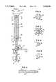
- FIG. 1is a side elevational view of a preferred embodiment of the instrument of the present invention.
- FIG. 2is a sectional view substantially as taken on line 2--2 of FIG. 1 on an enlarged scale and with portions omitted for clarity.
- FIG. 3is a sectional view substantially as taken on line 3--3 of FIG. 1 on an enlarged scale and with portions omitted for clarity.
- FIG. 4is a sectional view substantially as taken on line 4--4 of FIG. 1 on an enlarged scale for clarity.
- FIG. 5is a front elevational view of the distal end of the instrument of FIG. 1 on an enlarged scale for clarity.
- FIG. 6is a front elevational view of a accessory grip for the instrument of FIG. 1.
- FIG. 7is an exploded perspective view of the grip means of the instrument of FIG. 1.
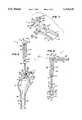
- FIG. 8is a side elevational view of the instrument of FIG. 1 shown in combination with a femoral hip prosthesis and a prepared femur.
- FIG. 9is a sectional view substantially as taken on line 9--9 of FIG. 8 with portions omitted, added and shown in broken lines for clarity.
- FIGS. 1-9A preferred embodiment of the instrument of the present invention is shown in FIGS. 1-9, and identified by the numeral 11.
- the instrument 11is for use with a long bone prosthesis such as a femoral hip prosthesis 13 (see FIGS. 8 and 9) having an elongated stem 15 for insertion into a long bone canal such as the prepared medullary canal 17 of a human femur 19, having a neck 21 extending from the upper or proximal end of the stem 15, and having a taper 23 on the upper or proximal end of the neck 21 for allowing a head (not shown) to be attached thereto as will now be apparent to those skilled in the art, or optionally having a head (not shown) permanently attached to the upper or proximal end of the neck 21.
- a long bone prosthesissuch as a femoral hip prosthesis 13 (see FIGS. 8 and 9) having an elongated stem 15 for insertion into a long bone canal such as the prepared medullary canal 17 of
- the lower or distal end of the stem 15has a longitudinal or central axis 25.
- the neck 21has a longitudinal or central axis 27.
- the axis 27 of the neck 21is located at an angle relative to the axis 25 of the stem 15. This angle between the axis 27 and the axis 25 can vary from prosthesis to prosthesis depending on the design of the prosthesis, the anatomy of the patient, etc.
- the neck 21typically has a first side 29 and a second side 30 with the first and second sides 29, 30 being opposed and substantially parallel to one another and being substantially flat side areas (see FIG. 9).
- the prosthesis 13may have an indentation 31 or the like in a proximal portion thereof (see FIG. 8) for receiving the distal end of a typical punch-type driver (not shown).
- the indentation 31is located in a position which allows access thereto from above the prosthesis 13 as the prosthesis 13 is being inserted or driven into the canal 17 and which allows force to be applied to the prosthesis 13 substantially along the axis 25 of the stem 15 as will now be apparent to those skilled in the art.
- the instrument 11 of the present inventionincludes an elongated shaft 33 having a first end 35 for engaging the prosthesis 13, having a second end 37 and having a longitudinal axis 39 between the first and second ends 35, 37.
- the shaft 33preferably includes an elongated post 41 and an elongated handle 43 for being manually held by a surgeon or the like and extending from one end of the post 41.
- the post 41 and handle 43 of the shaft 33are preferably constructed separate from one another and removably joined together by a set screw 45 or the like.
- the handle 43preferably includes a first end 47 and a second end 49.
- the second end 49preferably has an enlarged head 51 for allowing force to be applied thereby with hammers or the like.
- the first end 47preferably has a bore 53 formed therein along the longitudinal axis 39 of the shaft 33.
- the post 41 of the shaft 33preferably includes a first end 57 having a peg-like tip 59 for extending into the indentation 31 of the prosthesis 13 to thereby make secure contact with the prosthesis 13, and having a second end 61 for extending into the bore 53 in the first end 47 of the handle 43.
- the handle 43 of the shaft 33may be machined or otherwise constructed from stainless steel or the like with a substantial portion of the outer surface thereof knurled or otherwise designed so as to provide a secure manual grip for a surgeon or the like (see FIGS. 1, 8 and 9).
- the size of the handle 43may vary.
- the handle 43may have an overall length of approximately 6 inches (152.4 millimeters) and an outer diameter of approximately 1 inch (25.4 millimeters).
- An internally threaded bore 63is preferably provided through the handle 43 adjacent the second end 49 thereof transverse to and through the longitudinal axis 39 of the shaft 33 for reasons which will become apparent.
- An internally threaded bore 65preferably extends from the outer surface of the handle 43 to the bore 53 transverse to the longitudinal axis 39 of the shaft 33 for allowing the set screw 45 to secure the second end 61 of the post 41 to the first end 47 of the handle 43 (see FIG. 3).
- the post 41 of the shaft 33may also be machined or otherwise constructed from stainless steel or the like.
- the size of the post 41may also vary.
- the post 41may have an overall length of approximately 5 inches (127.0 millimeters) and an outer diameter of approximately 0.5 inch (12.7 millimeters).
- Flats 67are preferably machined or otherwise formed on opposite sides of the post 41 along all but the extreme first end 57 thereof to form a flange 69 at the extreme first end 57 thereof (see, in general, FIG. 5) for reasons which will hereinafter become apparent.
- the peg-like tip 59is shaped and sized to fit within the indentation 31 in the prosthesis 13.
- the peg-like tip 59may be cylindrical with a semi-spherical outer end as shown in FIGS. 1 and 5, etc., as will now be apparent to those skilled in the art.
- the instrument 11 of the present inventionincludes grip means 71 adjustably attached to the shaft 33 so that the relative position between the shaft 33 and the grip means 71 can be adjusted, for gripping the neck 21 of the prosthesis 13, and for rotating the prosthesis 13 about the longitudinal axis 25 of the stem 15 of the prosthesis 13 when the shaft 33 is rotated about the longitudinal axis 39 thereof.
- the grip means 71preferably includes a fork-like bracket member 73 having a first arm 75 for extending along and engaging the first side 29 of the neck 21 of the prosthesis 13 and having a second arm 77 for extending along and engaging the second side 30 of the neck 21 of the prosthesis 13 as clearly shown in FIG. 9. More specifically, the first and second arms 75, 77 coact to create a slot 79 therebetween (see FIG. 7) for receiving the neck 21 of the prosthesis 13.
- the grip means 71preferably includes a collar member 81 slidably positioned on the post 41 for connecting the bracket member 73 to the post 41.
- the collar member 81has a first aperture 83 for receiving the post 41.
- the cross-sectional shape and size of the aperture 83is preferably substantially the same as the cross-sectional shape and size of the portion of the post 41 having the flats 67 (i.e., all but the extreme first end 57 of the post 41 at the flange 69) so that the collar member 81 can easily slide up and down the portion of the post 41 having the flats 67 but will not rotate about the longitudinal axis of the post 41.
- the grip means 71preferably includes lock means 84 for locking the collar member 81 to the post 41 and for preventing movement of the collar member 81 on the post 41.
- the lock means 84preferably includes a lock screw 85 for screwing through the collar member 81 and abutting the post 41.
- the collar member 81may have a threaded aperture 87 therein communicating with the aperture 83 and the lock screw 85 may consist of a typical thumb screw or the like for screwing into the threaded aperture 87 and against the post 41 to allow the collar member 81 to be manually secured to the post 41, etc., as will now be apparent to those skilled in the art.
- the grip means 71preferably includes pivot means 89 for pivotally attaching the bracket member 73 to the collar member 81.
- the pivot means 89may consist of a typical cap screw or the like.
- the collar member 81preferably has an aperture 91 therethrough as clearly shown in FIG. 7 for allowing the pivot means 89 to extend therethrough.
- the bracket member 73preferably includes a first ear 93 having an aperture 95 therethrough for allowing the pivot means 89 to extend therethrough, and a second ear 97 spaced from the first ear 93 a distance at least equal to the width of the collar member 81 and having a threaded aperture 99 therethrough for screwably receiving the threaded end 90 of the pivot means 89.
- the bracket member 73may be pivotally attached to the collar member 81 by inserting the end of the collar member 81 between the first and second ears 93, 97 of the bracket member 73; aligning the apertures 91, 95, 99 with one another; inserting the pivot means 89 through the apertures 91 and 95; and then screwing the pivot means 89 into the threaded aperture 99.
- the grip means 71preferably includes lock means 101 for locking the bracket member 73 to the collar member 81 in a desired position and for preventing rotation of the bracket member 73 relative to the collar member 81.
- the lock means 101may include a lock screw 103 or the like for locking the collar member 81 to the pivot means 89 and for preventing movement of the collar member 81 about the pivot means 89.
- the collar member 81may have a threaded aperture 105 therein communicating with the aperture 91 and the lock screw 103 may consist of a typical thumb screw or the like for screwing into the threaded aperture 105 and against the pivot means 89 to allow the collar member 81 to be manually secured to the pivot means 89, etc., as will now be apparent to those skilled in the art.
- the bracket member 73 of the grip means 71may be machined or otherwise constructed from stainless steel or the like in any manner now apparent to those skilled in the art.
- the size of the bracket member 73may vary.
- the slot 79 formed between the arms 75, 77 of the bracket member 73may have an overall width of approximately 0.625 inches (15.88 millimeters) and an overall length of approximately 1.5 inches (38.1 millimeters).
- the collar member 81 of the grip means 71may be machined or otherwise constructed from stainless steel or the like in any manner now apparent to those skilled in the art.
- the size of the collar member 81may vary and is substantially controlled by the size of the post 41 of the shaft 33 and the size of the bracket member 73 of the grip means 71. That is, the aperture 83 through the collar member 81 is sized and shaped to slidably receive the post 41 and the width of the collar member 81 is sized to fit between the ears 93, 97 of the bracket member 73.
- the lock screw 85, pivot means 89, and lock means 101may be off-the-shelf stainless steel components or the like.
- the instrument 11may include an auxiliary handle 107 (see FIG. 6) for being secured to the handle 43 transverse to the longitudinal axis 39 of the shaft 33 (see FIG. 9) and for allowing a surgeon to easily rotate the instrument 11 about the longitudinal axis 39 of the shaft 33.
- the auxiliary handle 107preferably has an externally threaded end portion 109 for being screwed into the internally threaded bore 63 in the handle 43 of the shaft 33, and a grip portion 111 for being selectively grasped by a surgeon to rotate the shaft 33.
- the auxiliary handle 107may be machined or otherwise constructed from stainless steel or the like with a substantial portion of the outer surface of the grip portion 111 thereof knurled or otherwise designed so as to provide a secure manual grip for a surgeon or the like.
- the size of the auxiliary handle 107may vary. For example, for use with a typical femoral hip prosthesis 13, the auxiliary handle 107 may have an overall length of approximately 5 inches (127 millimeters) and an outer diameter of approximately 0.625 inch (15.88 millimeters).
- the externally threaded end portion 109is sized to screwably coact with the internally threaded bore 63 in the handle 43.
- the instrument 11is adjusted to fit the unique dimensions and angles of that individual prosthesis 13. That is, the collar member 81 is slid up and/or down on the post 41 and the bracket member 73 is pivoted relative to the collar member 81 until the bracket member 73 is positioned so that the arms 75, 77 thereof will extend along opposite sides 29, 30 of the neck 21 of the prosthesis 13 as clearly shown in FIG. 9 when the first end 57 of the post 41 is positioned against an appropriate portion of the prosthesis 13 (e.g., when the peg-like tip 59 of the first end 57 of the post 41 is inserted into the indentation 31 in the prosthesis 13 as clearly shown in FIG.
- the lock screws 85, 103can be loosened to allow easy adjustment of the collar member 81 and bracket member 73, and can be tightened to lock the collar member 81 and bracket member 73 in position as will now be apparent to those skilled in the art. Care should be taken to properly adjust the collar member 81 and bracket member 73 to insure that the bracket member 73 will not engage the taper 23 of the prosthesis 13 or an articulating surface (not shown) of the prosthesis 13, etc., when used to prevent scratching or other damage to such portions of the prosthesis 13.
- the present inventionprovides a universal instrument that has the ability to adapt to properly fit prostheses having varying neck lengths and/or neck angles; that provides rotational control of the prosthesis during implantation by using the neck of the prosthesis to provide an off-axis structure to attach to; and that can be used as a simple driver with or without such rotational control.
Landscapes
- Health & Medical Sciences (AREA)
- Transplantation (AREA)
- Orthopedic Medicine & Surgery (AREA)
- Heart & Thoracic Surgery (AREA)
- Cardiology (AREA)
- Oral & Maxillofacial Surgery (AREA)
- Engineering & Computer Science (AREA)
- Biomedical Technology (AREA)
- Physical Education & Sports Medicine (AREA)
- Vascular Medicine (AREA)
- Life Sciences & Earth Sciences (AREA)
- Animal Behavior & Ethology (AREA)
- General Health & Medical Sciences (AREA)
- Public Health (AREA)
- Veterinary Medicine (AREA)
- Prostheses (AREA)
Abstract
Description
Claims (11)
Priority Applications (1)
| Application Number | Priority Date | Filing Date | Title |
|---|---|---|---|
| US08/300,973US5514136A (en) | 1994-09-06 | 1994-09-06 | Surgical instrument for driving and rotating a long bone prosthesis |
Applications Claiming Priority (1)
| Application Number | Priority Date | Filing Date | Title |
|---|---|---|---|
| US08/300,973US5514136A (en) | 1994-09-06 | 1994-09-06 | Surgical instrument for driving and rotating a long bone prosthesis |
Publications (1)
| Publication Number | Publication Date |
|---|---|
| US5514136Atrue US5514136A (en) | 1996-05-07 |
Family
ID=23161388
Family Applications (1)
| Application Number | Title | Priority Date | Filing Date |
|---|---|---|---|
| US08/300,973Expired - Fee RelatedUS5514136A (en) | 1994-09-06 | 1994-09-06 | Surgical instrument for driving and rotating a long bone prosthesis |
Country Status (1)
| Country | Link |
|---|---|
| US (1) | US5514136A (en) |
Cited By (65)
| Publication number | Priority date | Publication date | Assignee | Title |
|---|---|---|---|---|
| USD383841S (en)* | 1995-11-14 | 1997-09-16 | Terray Corporation | Orthopaedic reconstruction plate bender |
| US5735857A (en)* | 1996-07-22 | 1998-04-07 | Bristol-Myers Squibb Co. | Prosthetic gripping instrument |
| US5743910A (en)* | 1996-11-14 | 1998-04-28 | Xomed Surgical Products, Inc. | Orthopedic prosthesis removal instrument |
| US5849015A (en)* | 1997-09-11 | 1998-12-15 | Bristol-Myers Squibb Company | Orthopaedic stem inserter with quick release lever and ratchet |
| US5885295A (en)* | 1996-08-07 | 1999-03-23 | Biomet, Inc. | Apparatus and method for positioning an orthopedic implant |
| US5888245A (en)* | 1997-05-21 | 1999-03-30 | Bristol-Myers Squibb Company | Rotational alignment guide for a prosthetic hip stem implant and method of using same |
| US5951564A (en)* | 1996-12-18 | 1999-09-14 | Bristol-Myers Squibb Company | Orthopaedic positioning apparatus |
| US5989259A (en)* | 1998-08-25 | 1999-11-23 | Johnson & Johnson Professional, Inc. | Femoral calcar stop for use with femoral stem inserter |
| US6022355A (en)* | 1997-07-02 | 2000-02-08 | Benoist Girard & Cie | Impaction hammer for bone chips |
| US6110179A (en)* | 1998-03-02 | 2000-08-29 | Benoist Girard Sas | Prosthesis inserter |
| US6165177A (en)* | 1998-12-24 | 2000-12-26 | Depuy Orthopaedics, Inc. | Alignment guide for insertion of stem prosthesis |
| US6203575B1 (en)* | 1998-01-16 | 2001-03-20 | Sulzer Orthopaedie Ag | Modular system for shaft prostheses |
| US6371991B1 (en)* | 1996-12-23 | 2002-04-16 | Depuy Orthopaedics, Inc. | Alignment guide for fluted prosthetic stems |
| US20030208256A1 (en)* | 2002-05-03 | 2003-11-06 | Dimatteo Kristian | Hypotube endoluminal device |
| US20040010262A1 (en)* | 2002-07-12 | 2004-01-15 | Parkinson Fred W. | Tool for gripping and orthopedic implant |
| US20040122437A1 (en)* | 2002-12-20 | 2004-06-24 | Dwyer Kimberly A. | Alignment device for modular implants and method |
| US20040249384A1 (en)* | 2003-02-04 | 2004-12-09 | Blaha J. David | Compacting broach |
| US20050149040A1 (en)* | 1994-09-02 | 2005-07-07 | Haines Timothy G. | Methods and apparatus for orthopedic surgical navigation and alignment |
| US20060015115A1 (en)* | 2004-03-08 | 2006-01-19 | Haines Timothy G | Methods and apparatus for pivotable guide surfaces for arthroplasty |
| US20060015117A1 (en)* | 2004-01-14 | 2006-01-19 | Haines Timothy G | Methods and apparatus for minimally invasive arthroplasty |
| US20060030853A1 (en)* | 2004-01-14 | 2006-02-09 | Haines Timothy G | Methods and apparatus for pinplasty bone resection |
| US20060155292A1 (en)* | 2002-09-19 | 2006-07-13 | Jeganath Krishnan | Implant clamp and method |
| US20060200162A1 (en)* | 2005-02-21 | 2006-09-07 | Zimmer Technology, Inc. | Total knee arthroplasty instruments |
| US20070244566A1 (en)* | 2002-12-20 | 2007-10-18 | Depuy Products, Inc. | Trialing system and method for modular hip joint replacement system |
| US20080255565A1 (en)* | 2006-11-20 | 2008-10-16 | Fletcher Henry H | Broach handle for minimally invasive hip replacement surgery |
| US20090099566A1 (en)* | 2007-10-10 | 2009-04-16 | Maness Megan A | Modular stem inserter |
| US7854737B2 (en) | 2002-12-20 | 2010-12-21 | Depuy Products, Inc. | Instrument and associated method of trailing for modular hip stems |
| US7935151B2 (en) | 2001-03-05 | 2011-05-03 | Hudson Surgical Design, Inc. | Femoral prosthetic implant |
| US8021368B2 (en) | 2004-01-14 | 2011-09-20 | Hudson Surgical Design, Inc. | Methods and apparatus for improved cutting tools for resection |
| US8114083B2 (en) | 2004-01-14 | 2012-02-14 | Hudson Surgical Design, Inc. | Methods and apparatus for improved drilling and milling tools for resection |
| US20130211412A1 (en)* | 2010-07-01 | 2013-08-15 | Finsbury (Development) Ltd | Impactor |
| US8603095B2 (en) | 1994-09-02 | 2013-12-10 | Puget Bio Ventures LLC | Apparatuses for femoral and tibial resection |
| US8740906B2 (en) | 2004-01-14 | 2014-06-03 | Hudson Surgical Design, Inc. | Method and apparatus for wireplasty bone resection |
| US8840622B1 (en)* | 2008-02-14 | 2014-09-23 | Nuvasive, Inc. | Implant installation assembly and related methods |
| US9220611B2 (en) | 2011-07-12 | 2015-12-29 | Zimmer, Inc. | Femoral component instrument |
| US9320601B2 (en) | 2011-10-20 | 2016-04-26 | 206 Ortho, Inc. | Method and apparatus for treating bone fractures, and/or for fortifying and/or augmenting bone, including the provision and use of composite implants |
| US10010609B2 (en) | 2013-05-23 | 2018-07-03 | 206 Ortho, Inc. | Method and apparatus for treating bone fractures, and/or for fortifying and/or augmenting bone, including the provision and use of composite implants |
| US20180193168A1 (en)* | 2015-07-27 | 2018-07-12 | Hip Innovation Technology, Llc. | Tool and status for separating a femoral cup from an acetabular ball in an implanted hip prosthesis |
| US10525168B2 (en) | 2010-10-20 | 2020-01-07 | 206 Ortho, Inc. | Method and apparatus for treating bone fractures, and/or for fortifying and/or augmenting bone, including the provision and use of composite implants, and novel composite structures which may be used for medical and non-medical applications |
| US10525169B2 (en) | 2010-10-20 | 2020-01-07 | 206 Ortho, Inc. | Method and apparatus for treating bone fractures, and/or for fortifying and/or augmenting bone, including the provision and use of composite implants, and novel composite structures which may be used for medical and non-medical applications |
| US10857261B2 (en) | 2010-10-20 | 2020-12-08 | 206 Ortho, Inc. | Implantable polymer for bone and vascular lesions |
| US10888436B2 (en) | 2017-02-01 | 2021-01-12 | Zimmer, Inc. | Tibial tray impactor |
| US11058796B2 (en) | 2010-10-20 | 2021-07-13 | 206 Ortho, Inc. | Method and apparatus for treating bone fractures, and/or for fortifying and/or augmenting bone, including the provision and use of composite implants, and novel composite structures which may be used for medical and non-medical applications |
| US11207197B2 (en) | 2019-08-01 | 2021-12-28 | DePuy Synthes Products, Inc. | Orthopaedic surgical instrument for total hip arthroplasty and associated orthopaedic surgical method of use |
| US11207109B2 (en) | 2010-10-20 | 2021-12-28 | 206 Ortho, Inc. | Method and apparatus for treating bone fractures, and/or for fortifying and/or augmenting bone, including the provision and use of composite implants, and novel composite structures which may be used for medical and non-medical applications |
| US11291483B2 (en) | 2010-10-20 | 2022-04-05 | 206 Ortho, Inc. | Method and apparatus for treating bone fractures, and/or for fortifying and/or augmenting bone, including the provision and use of composite implants |
| US20220233322A1 (en)* | 2019-10-01 | 2022-07-28 | Howmedica Osteonics Corp. | Shoulder prosthesis components and assemblies |
| US11432933B2 (en) | 2014-01-24 | 2022-09-06 | Howmedica Osteonics Corp. | Humeral implant anchor system |
| US11484627B2 (en) | 2010-10-20 | 2022-11-01 | 206 Ortho, Inc. | Method and apparatus for treating bone fractures, and/or for fortifying and/or augmenting bone, including the provision and use of composite implants, and novel composite structures which may be used for medical and non-medical applications |
| US11617660B2 (en)* | 2020-06-12 | 2023-04-04 | Tri-Sphere Holdings, LLC | Femoral component extractor |
| US11622869B2 (en)* | 2019-07-29 | 2023-04-11 | Tri-Sphere Holdings | Femoral component extractor |
| US11660200B2 (en) | 2016-03-25 | 2023-05-30 | Howmedica Osteonics Corp. | Stemless shoulder implant with fixation components |
| US11690635B2 (en)* | 2018-08-01 | 2023-07-04 | T.A.G. Medical Products Corporation Ltd. | Adjustable drilling device and a method for use thereof |
| WO2023131700A1 (en)* | 2022-01-07 | 2023-07-13 | Depuy Ireland Unlimited Company | Improvements in and relating to devices for surgical instrument impaction |
| US11766335B2 (en) | 2016-07-28 | 2023-09-26 | Howmedica Osteonics Corp. | Stemless prosthesis anchor component |
| US20230310176A1 (en)* | 2019-01-09 | 2023-10-05 | Shukla Medical | Implant extractor |
| US11779353B2 (en) | 2015-04-09 | 2023-10-10 | T.A.G. Medical Products Corporation Ltd. | Bone material removal device and a method for use thereof |
| US11844537B2 (en) | 2016-04-24 | 2023-12-19 | T.A.G. Medical Products Corporation Ltd. | Guiding device and method of using thereof |
| US11896242B2 (en) | 2014-10-19 | 2024-02-13 | T.A.G. Medical Products Corporation Ltd. | Kit including a guiding system and a bone material removal device |
| US11974925B2 (en) | 2017-09-25 | 2024-05-07 | Howmedica Osteonics Corp. | Patient specific stemless prosthesis anchor components |
| US12023253B2 (en) | 2014-01-24 | 2024-07-02 | Howmedica Osteonics Corp. | Humeral implant anchor system |
| US12102337B2 (en) | 2016-02-11 | 2024-10-01 | T.A.G. Medical Products Corporation Ltd. | Bone material removal device and a method for use thereof |
| US12167966B2 (en) | 2018-10-02 | 2024-12-17 | Howmedica Osteonics Corp. | Shoulder prosthesis components and assemblies |
| US12208021B2 (en) | 2018-10-04 | 2025-01-28 | Depuy Ireland Unlimited Company | Prosthesis extraction system |
| US12433754B2 (en) | 2017-12-11 | 2025-10-07 | Howmedica Osteonics Corp. | Method of use for stemless prosthesis anchor components |
Citations (3)
| Publication number | Priority date | Publication date | Assignee | Title |
|---|---|---|---|---|
| FR2615097A1 (en)* | 1987-05-12 | 1988-11-18 | Landos Applic Orthopediques Fs | Device for implanting/extracting a prosthesis, in particular a hip prosthesis |
| US5064427A (en)* | 1991-05-14 | 1991-11-12 | Intermedics Orthopedics, Inc. | Apparatus for inserting and withdrawing humeral prosthesis |
| FR2686016A1 (en)* | 1992-01-15 | 1993-07-16 | Icp Sa | Apparatus for extracting a femoral cement plug of a prosthesis |
- 1994
- 1994-09-06USUS08/300,973patent/US5514136A/ennot_activeExpired - Fee Related
Patent Citations (3)
| Publication number | Priority date | Publication date | Assignee | Title |
|---|---|---|---|---|
| FR2615097A1 (en)* | 1987-05-12 | 1988-11-18 | Landos Applic Orthopediques Fs | Device for implanting/extracting a prosthesis, in particular a hip prosthesis |
| US5064427A (en)* | 1991-05-14 | 1991-11-12 | Intermedics Orthopedics, Inc. | Apparatus for inserting and withdrawing humeral prosthesis |
| FR2686016A1 (en)* | 1992-01-15 | 1993-07-16 | Icp Sa | Apparatus for extracting a femoral cement plug of a prosthesis |
Cited By (101)
| Publication number | Priority date | Publication date | Assignee | Title |
|---|---|---|---|---|
| US9066804B2 (en) | 1994-09-02 | 2015-06-30 | Puget Bioventures Llc | Method and apparatus for femoral and tibial resection |
| US8603095B2 (en) | 1994-09-02 | 2013-12-10 | Puget Bio Ventures LLC | Apparatuses for femoral and tibial resection |
| US7967822B2 (en) | 1994-09-02 | 2011-06-28 | Hudson Surgical Design, Inc. | Methods and apparatus for orthopedic implants |
| US20050149040A1 (en)* | 1994-09-02 | 2005-07-07 | Haines Timothy G. | Methods and apparatus for orthopedic surgical navigation and alignment |
| USD383841S (en)* | 1995-11-14 | 1997-09-16 | Terray Corporation | Orthopaedic reconstruction plate bender |
| US5735857A (en)* | 1996-07-22 | 1998-04-07 | Bristol-Myers Squibb Co. | Prosthetic gripping instrument |
| US5885295A (en)* | 1996-08-07 | 1999-03-23 | Biomet, Inc. | Apparatus and method for positioning an orthopedic implant |
| US5743910A (en)* | 1996-11-14 | 1998-04-28 | Xomed Surgical Products, Inc. | Orthopedic prosthesis removal instrument |
| US5951564A (en)* | 1996-12-18 | 1999-09-14 | Bristol-Myers Squibb Company | Orthopaedic positioning apparatus |
| US6371991B1 (en)* | 1996-12-23 | 2002-04-16 | Depuy Orthopaedics, Inc. | Alignment guide for fluted prosthetic stems |
| US5888245A (en)* | 1997-05-21 | 1999-03-30 | Bristol-Myers Squibb Company | Rotational alignment guide for a prosthetic hip stem implant and method of using same |
| US6022355A (en)* | 1997-07-02 | 2000-02-08 | Benoist Girard & Cie | Impaction hammer for bone chips |
| US5849015A (en)* | 1997-09-11 | 1998-12-15 | Bristol-Myers Squibb Company | Orthopaedic stem inserter with quick release lever and ratchet |
| US6203575B1 (en)* | 1998-01-16 | 2001-03-20 | Sulzer Orthopaedie Ag | Modular system for shaft prostheses |
| US6110179A (en)* | 1998-03-02 | 2000-08-29 | Benoist Girard Sas | Prosthesis inserter |
| US5989259A (en)* | 1998-08-25 | 1999-11-23 | Johnson & Johnson Professional, Inc. | Femoral calcar stop for use with femoral stem inserter |
| US6165177A (en)* | 1998-12-24 | 2000-12-26 | Depuy Orthopaedics, Inc. | Alignment guide for insertion of stem prosthesis |
| US8088167B2 (en) | 2001-03-05 | 2012-01-03 | Hudson Surgical Design, Inc. | Femoral prosthetic implant |
| US8430932B2 (en) | 2001-03-05 | 2013-04-30 | Puget Bio Ventures LLC | Femoral prosthetic implant |
| US9192391B2 (en) | 2001-03-05 | 2015-11-24 | Puget Bioventures Llc | Method for minimally invasive total knee arthroplasty |
| US8062377B2 (en) | 2001-03-05 | 2011-11-22 | Hudson Surgical Design, Inc. | Methods and apparatus for knee arthroplasty |
| US9421022B2 (en) | 2001-03-05 | 2016-08-23 | Puget Bioventures Llc | Method and apparatus for total knee arthroplasty |
| US7935151B2 (en) | 2001-03-05 | 2011-05-03 | Hudson Surgical Design, Inc. | Femoral prosthetic implant |
| US20030208256A1 (en)* | 2002-05-03 | 2003-11-06 | Dimatteo Kristian | Hypotube endoluminal device |
| US20040010262A1 (en)* | 2002-07-12 | 2004-01-15 | Parkinson Fred W. | Tool for gripping and orthopedic implant |
| US7037311B2 (en) | 2002-07-12 | 2006-05-02 | Zimmer Technology, Inc. | Tool for gripping an orthopedic implant |
| US20060155292A1 (en)* | 2002-09-19 | 2006-07-13 | Jeganath Krishnan | Implant clamp and method |
| US7794503B2 (en) | 2002-12-20 | 2010-09-14 | Depuy Products, Inc. | Trialing system and method for modular hip joint replacement system |
| US20040122437A1 (en)* | 2002-12-20 | 2004-06-24 | Dwyer Kimberly A. | Alignment device for modular implants and method |
| US20100292806A1 (en)* | 2002-12-20 | 2010-11-18 | Depuy Products, Inc. | Trialing System and Method for Modular Hip Joint Replacement System |
| US7854737B2 (en) | 2002-12-20 | 2010-12-21 | Depuy Products, Inc. | Instrument and associated method of trailing for modular hip stems |
| US8529578B2 (en) | 2002-12-20 | 2013-09-10 | DePuy Synthes Products, LLC | Instrument and associated method of trialing for modular hip stems |
| US20110046745A1 (en)* | 2002-12-20 | 2011-02-24 | Depuy Products, Inc. | Instrument and associated method of trialing for modular hip stems |
| US20070244566A1 (en)* | 2002-12-20 | 2007-10-18 | Depuy Products, Inc. | Trialing system and method for modular hip joint replacement system |
| US7022141B2 (en)* | 2002-12-20 | 2006-04-04 | Depuy Products, Inc. | Alignment device for modular implants and method |
| US20040249384A1 (en)* | 2003-02-04 | 2004-12-09 | Blaha J. David | Compacting broach |
| US20060015117A1 (en)* | 2004-01-14 | 2006-01-19 | Haines Timothy G | Methods and apparatus for minimally invasive arthroplasty |
| US20060030853A1 (en)* | 2004-01-14 | 2006-02-09 | Haines Timothy G | Methods and apparatus for pinplasty bone resection |
| US9814539B2 (en) | 2004-01-14 | 2017-11-14 | Puget Bioventures Llc | Methods and apparatus for conformable prosthetic implants |
| US8114083B2 (en) | 2004-01-14 | 2012-02-14 | Hudson Surgical Design, Inc. | Methods and apparatus for improved drilling and milling tools for resection |
| US8287545B2 (en) | 2004-01-14 | 2012-10-16 | Hudson Surgical Design, Inc. | Methods and apparatus for enhanced retention of prosthetic implants |
| US8298238B2 (en) | 2004-01-14 | 2012-10-30 | Hudson Surgical Design, Inc. | Methods and apparatus for pivotable guide surfaces for arthroplasty |
| US8021368B2 (en) | 2004-01-14 | 2011-09-20 | Hudson Surgical Design, Inc. | Methods and apparatus for improved cutting tools for resection |
| US7857814B2 (en) | 2004-01-14 | 2010-12-28 | Hudson Surgical Design, Inc. | Methods and apparatus for minimally invasive arthroplasty |
| US7815645B2 (en) | 2004-01-14 | 2010-10-19 | Hudson Surgical Design, Inc. | Methods and apparatus for pinplasty bone resection |
| US8740906B2 (en) | 2004-01-14 | 2014-06-03 | Hudson Surgical Design, Inc. | Method and apparatus for wireplasty bone resection |
| US8353914B2 (en) | 2004-02-02 | 2013-01-15 | Hudson Surgical Design, Inc. | Methods and apparatus for improved profile based resection |
| US20060015115A1 (en)* | 2004-03-08 | 2006-01-19 | Haines Timothy G | Methods and apparatus for pivotable guide surfaces for arthroplasty |
| US20060200162A1 (en)* | 2005-02-21 | 2006-09-07 | Zimmer Technology, Inc. | Total knee arthroplasty instruments |
| US20080255565A1 (en)* | 2006-11-20 | 2008-10-16 | Fletcher Henry H | Broach handle for minimally invasive hip replacement surgery |
| US20090099566A1 (en)* | 2007-10-10 | 2009-04-16 | Maness Megan A | Modular stem inserter |
| US8840622B1 (en)* | 2008-02-14 | 2014-09-23 | Nuvasive, Inc. | Implant installation assembly and related methods |
| US20130211412A1 (en)* | 2010-07-01 | 2013-08-15 | Finsbury (Development) Ltd | Impactor |
| US11850323B2 (en) | 2010-10-20 | 2023-12-26 | 206 Ortho, Inc. | Implantable polymer for bone and vascular lesions |
| US10517654B2 (en) | 2010-10-20 | 2019-12-31 | 206 Ortho, Inc. | Method and apparatus for treating bone fractures, and/or for fortifying and/or augmenting bone, including the provision and use of composite implants |
| US11058796B2 (en) | 2010-10-20 | 2021-07-13 | 206 Ortho, Inc. | Method and apparatus for treating bone fractures, and/or for fortifying and/or augmenting bone, including the provision and use of composite implants, and novel composite structures which may be used for medical and non-medical applications |
| US11291483B2 (en) | 2010-10-20 | 2022-04-05 | 206 Ortho, Inc. | Method and apparatus for treating bone fractures, and/or for fortifying and/or augmenting bone, including the provision and use of composite implants |
| US11207109B2 (en) | 2010-10-20 | 2021-12-28 | 206 Ortho, Inc. | Method and apparatus for treating bone fractures, and/or for fortifying and/or augmenting bone, including the provision and use of composite implants, and novel composite structures which may be used for medical and non-medical applications |
| US10028776B2 (en) | 2010-10-20 | 2018-07-24 | 206 Ortho, Inc. | Method and apparatus for treating bone fractures, and/or for fortifying and/or augmenting bone, including the provision and use of composite implants |
| US11484627B2 (en) | 2010-10-20 | 2022-11-01 | 206 Ortho, Inc. | Method and apparatus for treating bone fractures, and/or for fortifying and/or augmenting bone, including the provision and use of composite implants, and novel composite structures which may be used for medical and non-medical applications |
| US11351261B2 (en) | 2010-10-20 | 2022-06-07 | 206 Ortho, Inc. | Method and apparatus for treating bone fractures, and/or for fortifying and/or augmenting bone, including the provision and use of composite implants |
| US10525168B2 (en) | 2010-10-20 | 2020-01-07 | 206 Ortho, Inc. | Method and apparatus for treating bone fractures, and/or for fortifying and/or augmenting bone, including the provision and use of composite implants, and novel composite structures which may be used for medical and non-medical applications |
| US10525169B2 (en) | 2010-10-20 | 2020-01-07 | 206 Ortho, Inc. | Method and apparatus for treating bone fractures, and/or for fortifying and/or augmenting bone, including the provision and use of composite implants, and novel composite structures which may be used for medical and non-medical applications |
| US10857261B2 (en) | 2010-10-20 | 2020-12-08 | 206 Ortho, Inc. | Implantable polymer for bone and vascular lesions |
| US9220611B2 (en) | 2011-07-12 | 2015-12-29 | Zimmer, Inc. | Femoral component instrument |
| US9901462B2 (en) | 2011-07-12 | 2018-02-27 | Zimmer, Inc. | Femoral component instrument |
| US9320601B2 (en) | 2011-10-20 | 2016-04-26 | 206 Ortho, Inc. | Method and apparatus for treating bone fractures, and/or for fortifying and/or augmenting bone, including the provision and use of composite implants |
| US10010609B2 (en) | 2013-05-23 | 2018-07-03 | 206 Ortho, Inc. | Method and apparatus for treating bone fractures, and/or for fortifying and/or augmenting bone, including the provision and use of composite implants |
| US11432933B2 (en) | 2014-01-24 | 2022-09-06 | Howmedica Osteonics Corp. | Humeral implant anchor system |
| US12023253B2 (en) | 2014-01-24 | 2024-07-02 | Howmedica Osteonics Corp. | Humeral implant anchor system |
| US11628067B2 (en) | 2014-01-24 | 2023-04-18 | Howmedica Osteonics Corp. | Humeral implant anchor system |
| US12310601B2 (en) | 2014-10-19 | 2025-05-27 | T.A.G. Medical Products Corporation Ltd. | Kit including a guiding system and a bone material removal device |
| US11896242B2 (en) | 2014-10-19 | 2024-02-13 | T.A.G. Medical Products Corporation Ltd. | Kit including a guiding system and a bone material removal device |
| US11779353B2 (en) | 2015-04-09 | 2023-10-10 | T.A.G. Medical Products Corporation Ltd. | Bone material removal device and a method for use thereof |
| AU2016298060B2 (en)* | 2015-07-27 | 2021-04-01 | Hip Innovation Technology, LLC | Tool and method for separating a femoral cup from an acetabular ball in an implanted hip prosthesis |
| US20190105182A1 (en)* | 2015-07-27 | 2019-04-11 | Hip Innovation Technology, Llc. | Tool and method for separating a femoral cup from an acetabular ball in an implanted hip prosthesis |
| US20180193168A1 (en)* | 2015-07-27 | 2018-07-12 | Hip Innovation Technology, Llc. | Tool and status for separating a femoral cup from an acetabular ball in an implanted hip prosthesis |
| US11020242B2 (en)* | 2015-07-27 | 2021-06-01 | Hip Innovation Technology, Llc. | Tool and status for separating a femoral cup from an acetabular ball in an implanted hip prosthesis |
| US11109984B2 (en)* | 2015-07-27 | 2021-09-07 | Hip Innovation Technology, Llc. | Tool and method for separating a femoral cup from an acetabular ball in an implanted hip prosthesis |
| US12102337B2 (en) | 2016-02-11 | 2024-10-01 | T.A.G. Medical Products Corporation Ltd. | Bone material removal device and a method for use thereof |
| US11660200B2 (en) | 2016-03-25 | 2023-05-30 | Howmedica Osteonics Corp. | Stemless shoulder implant with fixation components |
| US11844537B2 (en) | 2016-04-24 | 2023-12-19 | T.A.G. Medical Products Corporation Ltd. | Guiding device and method of using thereof |
| US12109121B2 (en) | 2016-07-28 | 2024-10-08 | Howmedica Osteonics Corp. | Stemless prosthesis anchor component |
| US11766335B2 (en) | 2016-07-28 | 2023-09-26 | Howmedica Osteonics Corp. | Stemless prosthesis anchor component |
| US10888436B2 (en) | 2017-02-01 | 2021-01-12 | Zimmer, Inc. | Tibial tray impactor |
| US11974925B2 (en) | 2017-09-25 | 2024-05-07 | Howmedica Osteonics Corp. | Patient specific stemless prosthesis anchor components |
| US12433754B2 (en) | 2017-12-11 | 2025-10-07 | Howmedica Osteonics Corp. | Method of use for stemless prosthesis anchor components |
| US11690635B2 (en)* | 2018-08-01 | 2023-07-04 | T.A.G. Medical Products Corporation Ltd. | Adjustable drilling device and a method for use thereof |
| US12369927B2 (en) | 2018-08-01 | 2025-07-29 | T.A.G. Medical Products Corporation Ltd. | Adjustable drilling device and a method for use thereof |
| US12167966B2 (en) | 2018-10-02 | 2024-12-17 | Howmedica Osteonics Corp. | Shoulder prosthesis components and assemblies |
| US12232969B2 (en) | 2018-10-02 | 2025-02-25 | Howmedica Osteonics Corp. | Shoulder prosthesis components and assemblies |
| US12208021B2 (en) | 2018-10-04 | 2025-01-28 | Depuy Ireland Unlimited Company | Prosthesis extraction system |
| US20230310176A1 (en)* | 2019-01-09 | 2023-10-05 | Shukla Medical | Implant extractor |
| US11622869B2 (en)* | 2019-07-29 | 2023-04-11 | Tri-Sphere Holdings | Femoral component extractor |
| US11207197B2 (en) | 2019-08-01 | 2021-12-28 | DePuy Synthes Products, Inc. | Orthopaedic surgical instrument for total hip arthroplasty and associated orthopaedic surgical method of use |
| US12343267B2 (en) | 2019-08-01 | 2025-07-01 | DePuy Synthes Products, Inc. | Orthopaedic surgical instrument for total hip arthroplasty and associated orthopaedic surgical method of use |
| US11642223B2 (en)* | 2019-10-01 | 2023-05-09 | Howmedica Osteonics Corp. | Shoulder prosthesis components and assemblies |
| US12370051B2 (en) | 2019-10-01 | 2025-07-29 | Howmedica Osteonics Corp. | Shoulder prosthesis components and assemblies |
| US20220233322A1 (en)* | 2019-10-01 | 2022-07-28 | Howmedica Osteonics Corp. | Shoulder prosthesis components and assemblies |
| US11617660B2 (en)* | 2020-06-12 | 2023-04-04 | Tri-Sphere Holdings, LLC | Femoral component extractor |
| WO2023131700A1 (en)* | 2022-01-07 | 2023-07-13 | Depuy Ireland Unlimited Company | Improvements in and relating to devices for surgical instrument impaction |
Similar Documents
| Publication | Publication Date | Title |
|---|---|---|
| US5514136A (en) | Surgical instrument for driving and rotating a long bone prosthesis | |
| US5976145A (en) | Calcar milling guide and system | |
| US5342363A (en) | Medical instrument and procedure | |
| US6106528A (en) | Modular intramedullary fixation system and insertion instrumentation | |
| US5879401A (en) | Acetabular trial | |
| US5957925A (en) | Orthopaedic milling instrument | |
| US7763031B2 (en) | Acetabular shell removal instrument | |
| US4601289A (en) | Femoral trial prosthesis/rasp assembly | |
| US6168631B1 (en) | Subtalar implant system and method for insertion and removal | |
| EP1463466B1 (en) | Accessory for implanting a hip endoprosthesis | |
| AU660724B2 (en) | Surgical reamer assembly | |
| US5476466A (en) | Orthopaedic positioning instrument | |
| AU2007200979B2 (en) | Compound offset handle | |
| US5728128A (en) | Femoral neck anteversion guide | |
| US7699847B2 (en) | Guide clamp for guiding placement of a guide wire in a femur | |
| US6165177A (en) | Alignment guide for insertion of stem prosthesis | |
| US6478799B1 (en) | Instruments and methods for use in performing knee surgery | |
| US8236004B2 (en) | Inserter for minimally invasive joint surgery having an interchangeable prosthesis engaging piston | |
| US5690640A (en) | Surgical instrument for use during connection of fractured bones | |
| US5868750A (en) | Orthopedic pin insertion tool | |
| JP5674785B2 (en) | Alignable prosthetic device, system, and method | |
| JP4496396B2 (en) | Retractor with replaceable retractor blade | |
| JPH06319761A (en) | Device for preparing annular bone for grafting transplant with caput of artificial joint | |
| CN101014291A (en) | Implant assembly device | |
| EP0959790A1 (en) | Ulnar cut guide alignment system |
Legal Events
| Date | Code | Title | Description |
|---|---|---|---|
| AS | Assignment | Owner name:WRIGHT MEDICAL TECHNOLOGY, INC., TENNESSEE Free format text:ASSIGNMENT OF ASSIGNORS INTEREST;ASSIGNOR:RICHELSOPH, MARC E.;REEL/FRAME:007135/0823 Effective date:19940906 | |
| AS | Assignment | Owner name:BANCBOSTON TRUST COMPANY OF NEW YORK Free format text:SECURITY INTEREST;ASSIGNOR:WRIGHT MEDICAL TECHNOLOGY, INC.;REEL/FRAME:007154/0131 Effective date:19940915 | |
| AS | Assignment | Owner name:STATE STREET BANK AND TRUST COMPANY, N.A., MASSACH Free format text:SECURITY INTEREST;ASSIGNOR:WRIGHT MEDICAL TECHNOLOGY, INC.;REEL/FRAME:008650/0778 Effective date:19970806 | |
| REMI | Maintenance fee reminder mailed | ||
| AS | Assignment | Owner name:CHASE MANHATTAN BANK, AS COLLATERAL AGENT, THE, NE Free format text:SECURITY INTEREST;ASSIGNOR:WRIGHT MEDICAL TECHNOLOGY, INC., A DELAWARE CORPORATION;REEL/FRAME:010506/0341 Effective date:19991220 | |
| LAPS | Lapse for failure to pay maintenance fees | ||
| FP | Expired due to failure to pay maintenance fee | Effective date:20000507 | |
| AS | Assignment | Owner name:WRIGHT MEDICAL TECHNOLOGY, INC., TENNESSEE Free format text:TERMINATION AND RELEASE OF SECURITY INTEREST;ASSIGNOR:STATE STREET BANK AND TRUST COMPANY, N.A.;REEL/FRAME:011571/0989 Effective date:19991220 | |
| AS | Assignment | Owner name:WRIGHT MEDICAL TECHNOLOGY, INC., TENNESSEE Free format text:TERMINATION AND RELEASE OF SECURITY INTEREST;ASSIGNOR:FIRST NATIONAL BANK OF BOSTON, THE, SUCCESSOR IN INTEREST TO BANCBOSTON TRUST CO. OF NEW YORK;REEL/FRAME:011571/0303 Effective date:19991220 | |
| AS | Assignment | Owner name:CHASE MANHATTAN BANK, AS COLLATERAL AGENT FOR SECU Free format text:GUARANTEE AND COLLATERAL AGREEMENT;ASSIGNOR:WRIGHT MEDICAL TECHNOLOGY, INC.;REEL/FRAME:012066/0233 Effective date:20010801 | |
| AS | Assignment | Owner name:WRIGHT MEDICAL TECHNOLOGY, INC., TENNESSEE Free format text:TERMINATION AND RELEASE OF SECURITY INTEREST;ASSIGNOR:CHASE MANHATTAN BANK, AS COLLATERAL AGENT FOR SECURED PARTIES, THE;REEL/FRAME:012066/0327 Effective date:20010801 | |
| STCH | Information on status: patent discontinuation | Free format text:PATENT EXPIRED DUE TO NONPAYMENT OF MAINTENANCE FEES UNDER 37 CFR 1.362 |