US5514076A - Surgical retractor - Google Patents
Surgical retractorDownload PDFInfo
- Publication number
- US5514076A US5514076AUS08/187,702US18770294AUS5514076AUS 5514076 AUS5514076 AUS 5514076AUS 18770294 AUS18770294 AUS 18770294AUS 5514076 AUS5514076 AUS 5514076A
- Authority
- US
- United States
- Prior art keywords
- tine
- surgical retractor
- shaft
- retractor
- improved surgical
- Prior art date
- Legal status (The legal status is an assumption and is not a legal conclusion. Google has not performed a legal analysis and makes no representation as to the accuracy of the status listed.)
- Expired - Fee Related
Links
Images


Classifications
- A—HUMAN NECESSITIES
- A61—MEDICAL OR VETERINARY SCIENCE; HYGIENE
- A61B—DIAGNOSIS; SURGERY; IDENTIFICATION
- A61B17/00—Surgical instruments, devices or methods
- A61B17/02—Surgical instruments, devices or methods for holding wounds open, e.g. retractors; Tractors
- A—HUMAN NECESSITIES
- A61—MEDICAL OR VETERINARY SCIENCE; HYGIENE
- A61F—FILTERS IMPLANTABLE INTO BLOOD VESSELS; PROSTHESES; DEVICES PROVIDING PATENCY TO, OR PREVENTING COLLAPSING OF, TUBULAR STRUCTURES OF THE BODY, e.g. STENTS; ORTHOPAEDIC, NURSING OR CONTRACEPTIVE DEVICES; FOMENTATION; TREATMENT OR PROTECTION OF EYES OR EARS; BANDAGES, DRESSINGS OR ABSORBENT PADS; FIRST-AID KITS
- A61F2/00—Filters implantable into blood vessels; Prostheses, i.e. artificial substitutes or replacements for parts of the body; Appliances for connecting them with the body; Devices providing patency to, or preventing collapsing of, tubular structures of the body, e.g. stents
- A61F2/02—Prostheses implantable into the body
- A61F2/30—Joints
- A61F2002/30001—Additional features of subject-matter classified in A61F2/28, A61F2/30 and subgroups thereof
- A61F2002/30003—Material related properties of the prosthesis or of a coating on the prosthesis
- A61F2002/3006—Properties of materials and coating materials
- A61F2002/30092—Properties of materials and coating materials using shape memory or superelastic materials, e.g. nitinol
- A—HUMAN NECESSITIES
- A61—MEDICAL OR VETERINARY SCIENCE; HYGIENE
- A61F—FILTERS IMPLANTABLE INTO BLOOD VESSELS; PROSTHESES; DEVICES PROVIDING PATENCY TO, OR PREVENTING COLLAPSING OF, TUBULAR STRUCTURES OF THE BODY, e.g. STENTS; ORTHOPAEDIC, NURSING OR CONTRACEPTIVE DEVICES; FOMENTATION; TREATMENT OR PROTECTION OF EYES OR EARS; BANDAGES, DRESSINGS OR ABSORBENT PADS; FIRST-AID KITS
- A61F2210/00—Particular material properties of prostheses classified in groups A61F2/00 - A61F2/26 or A61F2/82 or A61F9/00 or A61F11/00 or subgroups thereof
- A61F2210/0014—Particular material properties of prostheses classified in groups A61F2/00 - A61F2/26 or A61F2/82 or A61F9/00 or A61F11/00 or subgroups thereof using shape memory or superelastic materials, e.g. nitinol
Definitions
- This inventionrelates to a surgical retractor for use in various surgical procedures to maintain the exposure of underlying anatomical structures following an incision.
- retractorsare used to facilitate the surgical exposure of tissues.
- Traditional surgical retractorsare rigid metallic structures. The size and shape of the retractor depends in part on the size of the incision and nature of the anatomical structures exposed. For example, in abdominal surgery the surgeon may need to temporarily displace large internal organs. In this instance a large, rigid, relatively wide stainless steel retractor is typically used.
- a "skin hook" or skin impaling retractoris typically used. Skin hooks have been constructed using a relatively rigid stainless steel shank and hook attached to a handle. Other variations on skin hooks or skin impaling devices have included shanks and hooks made of cannulated needle stock.
- the present inventionis a surgical retractor which exhibits a controlled release force to minimize tissue damage.
- the surgical retractormay also be deformed to permit the technician to be positioned away from the operating field.
- the preferred surgical retractoris made from an alloy known as "nitinol".
- the surgical retractorcombines a non damaging grasping end with a flexible shaft capable of allowing sufficient force to maintain exposure of the incision while simultaneously flexing the shaft away from the operating area.
- nitinolis the preferred material other superelastic metallic alloys can also be used.
- Part of the nature of a superelastic metallic alloyis that when a physical force is applied to it, there will be an initial phase where a relatively linear relationship will exist between the amount of force exerted and the amount of deflection then present in the wire.
- the operatorWhen properly shaped and formed the operator will be able to quickly learn to feel when the retractor is about to release, and reduce the applied force.
- the amount of force necessary to release the grasping portion of the surgical retractoris set to be below the amount which would cause tissue damage.
- excessive force applied by a operatorwould only cause the retractor to release, instead of causing tissue damage to the patient.
- a retractor having a superelastic shaftrepresents an advance in the art by allowing the incision to be grasped, then having force applied to maintain exposure of underlying structures, then utilizing the superelastic nature of the shaft to conform to the outer surface of the body being operated on. This ability allows the force to be maintained by the technician in an offset manner and increases operating room efficiency by freeing up space.
- An additional benefit of a superelastic shaftis that it allows a system of weights to be attached to the handle, thus dispensing with the necessity of a technician altogether.
- the surgical retractorcomprises a handle, a flexible shaft and a tine shaped so as to allow it to grasp or hold tissue.
- Variations on the basic designare envisaged which would include retractors having shafts of differing length, geometry, diameter and/or with variable or tapering diameter. This would allow such retractors to be used in different kinds of surgical procedures. For example, abdominal surgery requires the displacement of large masses of tissue. This would require a retractor with a diameter between 0.030 inches and 0.25 inches and a length between 3 inches and 18 inches. An application such as bone surgery would utilize an even heavier retractor, with a diameter between 0.050 inches and 0.30 inches and a length between 3 inches and 18 inches.
- a retractorwith a diameter between 0.015 inches and 0.035 inches and a length between 3 inches and 18 inches.
- the lightest retractorscould be used for ophthalmic or neurosurgery and would have a diameter between 0.002 inches and 0.015 inches and a length between 2 inches and 12 inches.
- the retractorcould be made to be either disposable or reusable, depending on the preference of the user. Further, the surgical retractor may be used for dental, veterinary, mortuary applications as well as other industrial purposes.
- various types of coatingsmay be placed over the surgical retractor or portion of the surgical retractor to facilitate its use.
- FIG. 1is a longitudinal view of a surgical retractor
- FIG. 2shows an alternative form of the tissue grasping end of the surgical retractor
- FIG. 3shows an alternative form of the tissue grasping end of the surgical retractor
- FIG. 4shows an alternative form of the tissue grasping end of the surgical retractor
- FIG. 5shows an alternative form of the distal tip portion of a tine
- FIG. 6shows an alternative form of the distal tip portion of a tine
- FIG. 7shows an alternative form of the distal tip portion of a tine
- FIG. 8shows an alternative form of the distal tip portion of a tine
- FIG. 9shows an alternative form of the surgical retractor having multiple tines
- FIG. 10shows an alternative form of the surgical retractor
- FIG. 11shows an alternative form of the surgical retractor
- FIG. 12shows an alternative form of the surgical retractor
- FIG. 13shows an alternative form of the surgical retractor
- FIG. 14shows an alternative form of the surgical retractor
- FIG. 15shows the use of an exemplary form of the surgical retractor during surgery
- FIG. 16shows the surgical retractor being used in hand surgery
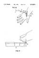
- FIG. 17illustrates the surgical retractor's ability to conform to the outer contours of the patient's body during surgery.
- FIG. 18shows two force/deflection curves demonstrating the release force present in the surgical retractor.
- the surgical retractors' propertiesare dependant in part upon metallurgical properties.
- Metallic alloys possessing the shape memory effect (SME)were first discovered in gold- cadmium alloys. Since then, many other alloys exhibiting the shape memory effect have also been discovered. These include copper-zinc, copper-zinc-aluminum, copper-nickel-aluminum, iron-platinum, and nickel-titanium.
- the best known and most widely used shape memory alloysare those based on near stoichiometric amounts of nickel and titanium, these alloys are commonly referred to as nitinol.
- the particular mechanical properties of a shape memory/superelastic metallic alloyare primarily determined by its chemical composition and its processing history.
- the alloywill exist in either one or the other, or combinations of two crystallographic states. Austenite is the parent crystallographic state and exists at higher temperatures. Martensite is the other state and it is formed either by subjecting the alloy to lower temperatures or by placing mechanical or physical stress on the alloy while it is in the austenitic state. Transition temperatures between these two states can be experimentally determined for a particular alloy. Alloy chemistry and thermo-mechanical forming of the alloy are primarily responsible for determining the alloy's characteristics. Processing history, including high temperature annealing as well as low temperature forming and deformation, also play a role in determining the crystallographic state of the material.
- transitional temperatureswhich define the alloy's mechanical characteristics are predictable.
- Standard transitional temperature designationshave been given as: Ms for the start of the transition to the martensitic phase, Mf for completion of the transition to martensite, As for the start of the transition to the austenitic phase, and Af for the completed transition to the austenitic phase.
- Shape memory effectoccurs as the result of a piece of shape memory alloy being deformed while in the lower temperature martensitic state, then being reheated to a higher temperature which causes the alloy to reform in the austenitic state.
- the alloy's shapewill return to the prior shape prior to being deformed while in the martensitic state.
- Shape memory trainingoccurs when a shape memory/superelastic metallic alloy is annealed (heat treated) while restrained in a certain shape. The trained shape will then be maintained unless it is deformed while in the low temperature martensitic phase.
- temperature changeis one way of controlling the crystallographic state of a shape memory/superelastic metallic alloy.
- the present inventionrelies primarily on superelasticity.
- Superelasticityis also based on phase transformation from austenite to martensite. Phase transformation from austenite to martensite also occurs when the alloy temperature is above Af and a physically restraining stress is applied to the alloy. As long as the restraint is in place, the portion of the alloy which is receiving the stress will revert to the martensitic phase, which will remain as long as the stress is maintained. Unless the shape recovery limits have been exceeded, when the stress is released, the alloy will return to its original austenitic phase and shape as long as the temperature has been maintained above Af.
- the present inventionuses the superelastic, kink resistant properties of superelastic nickel-titanium in two different ways.
- the relatively straight nature of the shaftcan be bent to a much greater degree than can traditional materials, and yet always return to a straight (or other desired) configuration.
- the second use of superelasticity in the inventiondeals with the nature of the release force present in the distal tissue grasping end of the device. Both of the uses of superelasticity in this invention will be discussed below.
- FIG. 1illustrates a precision releasable surgical retractor embodying the basic features of the invention.
- the retractor 10generally comprises an elongated shaft 13, having a proximal end 12, a distal end 14.
- a tine 15is connected to the distal end 14 of the elongated shaft 13 and a handle 11 is attached to the proximal end 12 of the shaft.
- the tine 15 attached to the distal end 14 of the shaft 13,has a shape adapted to grasp animal tissue trained into it by methods and means to be discussed below.
- the elongated shaft 13is preferably constructed from nitinol, which is a near stoichiometric alloy of nickel and titanium. Several methods can be used to effect the mechanical nature of the elongated shaft 13 that is the primary element of the invention.
- a number of tip variationsare contemplated within the scope of the invention. These include a tip or "hook” 16 which is formed at the end of the tine 15.
- the hook 16may be sharpened, rounded, square, or blunt.
- the tine 15may be semicircular, square, angular or compound. Further, it would be possible to include multiple tines 15 attached to a common shaft 17. Each of these shapes may be combined to create a surgical retractor specifically adapted for a particular surgical procedure.
- metallurgical composition or stateare also contemplated. These include constructing the entire surgical retractor from nitinol but having different heat treatments and/or other physical processing at different positions along the shaft 13, and tine 15 portions. This would allow, for example, a retractor having a superelastic tine 15 with a shaft 13 exhibiting the shape memory effect.
- the force required to release the superelastic (austenitic) grasping meanswould be less than the force required to deform the (martensitic) shape memory shaft.
- the shaft 13would be reversibly deformed to any shape the physician desired; upon sterilizing (which requires heating) it would resume its previously "learned", presumably straight, "normal” shape.
- the preferred method of training the tissue grasping shape into the distal end 14 of the shaftis by thermo mechanical forming. This is accomplished by restraining the nitinol wire around a mandrel in the exact shape desired, and maintaining the restraint while the wire is heat treated to temperatures between and about 350 degrees C and 575 degrees C for a period of 2 to 60 minutes. The wire is then rapidly cooled. This treatment allows the distal end 14 (or any other portion) of the wire to be permanently trained to any shape desired.
- FIGS. 2, 3 and 4are illustrative of the possible shapes which could be trained into the distal end 14 of the wire by using this method.
- the trained shapewhen stress is applied to the shape, temporarily deforming it, upon releasing the stress the trained shape will instantly return.
- thisis embodied by the tissue grasping distal end of the wire being stressed (deformed) beyond its release point when being used in surgery and then instantly returning to its permanently trained shape.
- the release forceis designed and calculated to be below that amount of force necessary to cause damage to the tissue exposed and retracted during the course of the operation.
- the release force designed into the tinecan be controlled by a number of different means. It is known in the art to add small amounts of vanadium, chromium or iron to the alloy to alter its transitional temperature characteristics. Other methods of altering the mechanical characteristics of the alloy include heat annealing or cold working. By centerless grinding or other methods, the diameter of the wire can be varied, offering another technique for controlling the release force of the tissue grasping distal end.
- the handle 11can be constructed from any suitable material such as metal, polymers or composites. Requirements for the handle 11 include durability and suitability to sterilization. Shape, weight, length, and diameter can be varied to meet the needs of the technician using the retractor. Attachment of the shaft 13 to the handle 11 could be accomplished by any of a variety of traditional means, including gluing, welding, soldering, crimping, molding or by mechanical connections. A variable system of weighted handles, permit the surgical retractor to be used without a technician.
- FIGS. 2, 3, and 4show possible variations on the tine 15 of the retractor.
- FIG. 2illustrates a semi circular variation
- FIG. 3shows a sharply angled version
- FIG. 4shows a compound or combination of rounded and sharply angled shapes. These are by way of illustration only and are not intended to be limiting.
- FIGS. 5, 6, 7, and 8The possible variations on the distal, tip portion 16 of the tine 15 are shown in FIGS. 5, 6, 7, and 8. These vary between sharpened and non sharpened and would vary for different intended purposes of the retractor. For example, using a skin hook version of the retractor might require a sharpened tip to better grasp the skin tissue wished to be retracted. Orthopedic surgery might require a blunt tip with a shaft of larger diameter.
- FIG. 9An alternative embodiment, commonly referred to as a rake, is shown in FIG. 9, wherein multiple tines 15 are attached to a common cross member 17.
- the tineswould preferably be formed from nitinol, but could alternatively be of any material displaying superelastic properties.
- the cross member 17is only a structure for mounting the tines, it could be constructed from any material able to support the forces generated by the normal use of the retractor. In selecting the material to be used for the cross member, biocompatibility also needs to be considered, although a wide variety of metallic or plastic materials are useful.
- FIG. 10Another alternate embodiment of the invention is shown in FIG. 10 wherein multiple tines 15 are attached at the proximal end to a first cross member 17 and at the distal end to a second cross member 18.
- This embodimentwould be used in procedures requiring a relatively long incision into delicate tissue where other grasping means would be inappropriate.
- the cross members 17 and 18are mainly used for mounting the tines, they could be constructed from any material able to withstand the forces generated by the normal use of the retractor. In selecting the material to be used for the cross members, biocompatibility must also be considered.
- FIG. 11represents an alternative embodiment of the invention wherein multiple tines 15 of unequal lengths are attached to a common cross member 17. This embodiment would be used in procedures requiring an incision to be retracted unequally along its length.
- FIG. 12shows another rake configuration of the invention.
- superelastic tines 15are radially attached to a handle 11.
- This version of the inventionmight be used in a procedure where a relatively long incision is required.
- FIG. 13shows a further alternative embodiment of the invention, one which is formed from flattened or sheet superelastic material and trained to assume a specified shape.
- the retractor 19(minus handle) is made of a single piece of sheet superelastic material which is cut to form shafts 20. The individual tines 21 are then trained into a desired shape.
- FIG. 14is illustrative of another alternative embodiment of the invention, one having dual, opposing tines 22 attached to a handle 11.
- the tineswould be placed about the outer periphery of the body part intended to be retracted 23.
- the tines 22will grasp the incision from both sides equally, thus allowing one technician to do the work of two.
- FIG. 16shows the invention as it would be used in hand surgery. Following an incision 24 by the surgeon, the tine 15, is inserted into the incision 24 and force is applied by the technician to the handle 11, thus facilitating exposure of the underlying anatomical structures.
- the second use of superelasticity in the inventionis also shown in FIG. 16. This occurs after initial placement of the retractor 10 in the incision 24. Following initial placement of the retractor 10, the technician then moves the handle 11 to a position allowing more room for the physician and other operating room personnel. This makes it possible to simultaneously maintain retraction of the incision and conform the superelastic shaft to the outer contours of the patient's body with a single application of force.
- FIG. 17shows a similar use of the invention, with before and after flexing the superelastic shaft 13 configurations.
- FIG. 18shows force deflection curves for two different diameter retractors, 0.016 inches and 0.025 inches.
- a linear relationship between force and deflectionbetween 25 and 26 on the graph.
- the linear relationshipbegins to lessen; this is where stress induced martensite begins to form (causing superelasticity to exist).
- stress induced martensitebegins to form (causing superelasticity to exist).
Landscapes
- Health & Medical Sciences (AREA)
- Life Sciences & Earth Sciences (AREA)
- Surgery (AREA)
- Heart & Thoracic Surgery (AREA)
- Engineering & Computer Science (AREA)
- Biomedical Technology (AREA)
- Nuclear Medicine, Radiotherapy & Molecular Imaging (AREA)
- Medical Informatics (AREA)
- Molecular Biology (AREA)
- Animal Behavior & Ethology (AREA)
- General Health & Medical Sciences (AREA)
- Public Health (AREA)
- Veterinary Medicine (AREA)
- Surgical Instruments (AREA)
Abstract
Description
This invention relates to a surgical retractor for use in various surgical procedures to maintain the exposure of underlying anatomical structures following an incision.
In surgical operations, retractors are used to facilitate the surgical exposure of tissues. Traditional surgical retractors are rigid metallic structures. The size and shape of the retractor depends in part on the size of the incision and nature of the anatomical structures exposed. For example, in abdominal surgery the surgeon may need to temporarily displace large internal organs. In this instance a large, rigid, relatively wide stainless steel retractor is typically used. For superficial or topical surgeries, such as in hand or cosmetic surgery, a "skin hook" or skin impaling retractor is typically used. Skin hooks have been constructed using a relatively rigid stainless steel shank and hook attached to a handle. Other variations on skin hooks or skin impaling devices have included shanks and hooks made of cannulated needle stock.
Problems arise, however, in the use of traditional surgical retraction devices. Stainless steel skin hooks are known to tear skin and damage other tissue if too much force is inadvertently applied to the retractor by the technician or surgeon. Unnecessary tissue damage resulting from an operation can lengthen healing time and increase patient discomfort, thereby increasing expense and risk of the procedure. This problem is accentuated by "crowding" of the operating area with technicians and retractors. This problem is also exacerbated by the fact that the shaft of most skin hook type retractors is relatively rigid and inflexible. Thus, the retractor's use is limited to a straight shaft configuration. If the shape recovery limit of the shaft is exceeded, permanent deformation or kinking of the shaft will occur, making the retractor useless. The straight shaft retractor severely restricts the position of the technician and limits the mobility of the surgeon.
Therefore there is a need for surgical retractor which addresses these problems.
The present invention is a surgical retractor which exhibits a controlled release force to minimize tissue damage. The surgical retractor may also be deformed to permit the technician to be positioned away from the operating field.
The preferred surgical retractor is made from an alloy known as "nitinol". The surgical retractor combines a non damaging grasping end with a flexible shaft capable of allowing sufficient force to maintain exposure of the incision while simultaneously flexing the shaft away from the operating area. Although nitinol is the preferred material other superelastic metallic alloys can also be used.
Surgical retractors made with shafts and hooks of nitinol or other superelastic alloys possess the characteristic of remarkable shape recovery, on the order of 10 to 50 times that of traditional materials such as stainless steel. The shape recovery characteristics of nickel-titanium and other shape memory/superelastic metallic alloys is a function of the alloy's inherent superelasticity. Most importantly, this property allows a retractor to be constructed wherein the hook or grasping means possesses a relatively low, but predictable and controllable, release force. Part of the nature of a superelastic metallic alloy is that when a physical force is applied to it, there will be an initial phase where a relatively linear relationship will exist between the amount of force exerted and the amount of deflection then present in the wire. Following the linear phase, however, there will be a plateau reached where an increased amount of deflection will not result in additional force, but, rather, in a relatively similar amount of force. When the amount of force necessary to cause the grasping means to change shape is exceeded, the retractor simply releases and returns to its predetermined, previously trained shape. Since superelasticity is a temperature dependant phenomenon, it is desireable to use alloys and/or processing techniques to ensure that at least the grasping means is superelastic at or below the ambient temperature of the operating room. This is ordinarily around 16 degrees C.
When properly shaped and formed the operator will be able to quickly learn to feel when the retractor is about to release, and reduce the applied force. By design, the amount of force necessary to release the grasping portion of the surgical retractor is set to be below the amount which would cause tissue damage. Thus, inadvertent, excessive force applied by a operator would only cause the retractor to release, instead of causing tissue damage to the patient.
Another problem of the prior art relates to crowding the operating field by retractor wielding technicians. The use of traditional, relatively rigid retractors, severely restricts the movements of the surgeon. This is due to the nature of traditional materials (such as stainless steel) which possess a limited amount of shape recovery. Because this property substantially limits flexibility of the shaft, the technician is required to apply force to maintain the exposure of the incision in a manner such that the shaft of the retractor is in a straight line configuration. This restriction severely limits the ability of the technician to get "out of the way" of the physician and other personnel. A retractor having a superelastic shaft, however, represents an advance in the art by allowing the incision to be grasped, then having force applied to maintain exposure of underlying structures, then utilizing the superelastic nature of the shaft to conform to the outer surface of the body being operated on. This ability allows the force to be maintained by the technician in an offset manner and increases operating room efficiency by freeing up space. An additional benefit of a superelastic shaft is that it allows a system of weights to be attached to the handle, thus dispensing with the necessity of a technician altogether.
The surgical retractor comprises a handle, a flexible shaft and a tine shaped so as to allow it to grasp or hold tissue. Variations on the basic design are envisaged which would include retractors having shafts of differing length, geometry, diameter and/or with variable or tapering diameter. This would allow such retractors to be used in different kinds of surgical procedures. For example, abdominal surgery requires the displacement of large masses of tissue. This would require a retractor with a diameter between 0.030 inches and 0.25 inches and a length between 3 inches and 18 inches. An application such as bone surgery would utilize an even heavier retractor, with a diameter between 0.050 inches and 0.30 inches and a length between 3 inches and 18 inches. At the other extreme would be hand or plastic surgery, where only limited amounts of tissue would need retraction, requiring a retractor with a diameter between 0.015 inches and 0.035 inches and a length between 3 inches and 18 inches. The lightest retractors could be used for ophthalmic or neurosurgery and would have a diameter between 0.002 inches and 0.015 inches and a length between 2 inches and 12 inches. By altering the diameter, geometry, length, alloy composition and/or heat treatment of the shaft, it is possible to design a retractor which has characteristics which make it ideal for a particular application. It would also be relatively easy to alter the shape of the grasping end (semicircular, angular, compound) and/or the nature of the tip configuration (blunt, round, sharp) to further adapt the surgical retractor.
The retractor could be made to be either disposable or reusable, depending on the preference of the user. Further, the surgical retractor may be used for dental, veterinary, mortuary applications as well as other industrial purposes.
Finally, various types of coatings, may be placed over the surgical retractor or portion of the surgical retractor to facilitate its use.
Other aspects and advantages of the invention will become apparent from the following detailed description, and the accompanying drawings, illustrating by way of example the features of the invention.
The drawings depict illustrative and exemplary forms of the surgical retractor and identical reference numerals refer to identical structure throughout the various figures, in which:
FIG. 1 is a longitudinal view of a surgical retractor;
FIG. 2 shows an alternative form of the tissue grasping end of the surgical retractor;
FIG. 3 shows an alternative form of the tissue grasping end of the surgical retractor;
FIG. 4 shows an alternative form of the tissue grasping end of the surgical retractor;
FIG. 5 shows an alternative form of the distal tip portion of a tine;
FIG. 6 shows an alternative form of the distal tip portion of a tine:
FIG. 7 shows an alternative form of the distal tip portion of a tine;
FIG. 8 shows an alternative form of the distal tip portion of a tine;
FIG. 9 shows an alternative form of the surgical retractor having multiple tines;
FIG. 10 shows an alternative form of the surgical retractor;
FIG. 11 shows an alternative form of the surgical retractor;
FIG. 12 shows an alternative form of the surgical retractor;
FIG. 13 shows an alternative form of the surgical retractor;
FIG. 14 shows an alternative form of the surgical retractor;
FIG. 15 shows the use of an exemplary form of the surgical retractor during surgery;
FIG. 16 shows the surgical retractor being used in hand surgery;
FIG. 17 illustrates the surgical retractor's ability to conform to the outer contours of the patient's body during surgery; and,
FIG. 18 shows two force/deflection curves demonstrating the release force present in the surgical retractor.
Overview
The surgical retractors' properties are dependant in part upon metallurgical properties. Metallic alloys possessing the shape memory effect (SME) were first discovered in gold- cadmium alloys. Since then, many other alloys exhibiting the shape memory effect have also been discovered. These include copper-zinc, copper-zinc-aluminum, copper-nickel-aluminum, iron-platinum, and nickel-titanium. The best known and most widely used shape memory alloys are those based on near stoichiometric amounts of nickel and titanium, these alloys are commonly referred to as nitinol.
In addition to the shape memory effect, some of these alloys also possess a characteristic called superelasticity. These properties are related, and are explained in relation to each other.
The particular mechanical properties of a shape memory/superelastic metallic alloy are primarily determined by its chemical composition and its processing history. In general, the alloy will exist in either one or the other, or combinations of two crystallographic states. Austenite is the parent crystallographic state and exists at higher temperatures. Martensite is the other state and it is formed either by subjecting the alloy to lower temperatures or by placing mechanical or physical stress on the alloy while it is in the austenitic state. Transition temperatures between these two states can be experimentally determined for a particular alloy. Alloy chemistry and thermo-mechanical forming of the alloy are primarily responsible for determining the alloy's characteristics. Processing history, including high temperature annealing as well as low temperature forming and deformation, also play a role in determining the crystallographic state of the material. Following standard material and processing specifications, the transitional temperatures which define the alloy's mechanical characteristics are predictable. Standard transitional temperature designations have been given as: Ms for the start of the transition to the martensitic phase, Mf for completion of the transition to martensite, As for the start of the transition to the austenitic phase, and Af for the completed transition to the austenitic phase.
The shape memory effect of these alloys has been known much longer than superelasticity. Shape memory effect occurs as the result of a piece of shape memory alloy being deformed while in the lower temperature martensitic state, then being reheated to a higher temperature which causes the alloy to reform in the austenitic state. When the crystallographic nature of the alloy is completely austenitic, the alloy's shape will return to the prior shape prior to being deformed while in the martensitic state. Shape memory training occurs when a shape memory/superelastic metallic alloy is annealed (heat treated) while restrained in a certain shape. The trained shape will then be maintained unless it is deformed while in the low temperature martensitic phase. Upon reheating to the austenitic state, the original shape which was learned in the annealing process will be "remembered" and returned to. Thus, temperature change is one way of controlling the crystallographic state of a shape memory/superelastic metallic alloy.
The present invention relies primarily on superelasticity. Superelasticity is also based on phase transformation from austenite to martensite. Phase transformation from austenite to martensite also occurs when the alloy temperature is above Af and a physically restraining stress is applied to the alloy. As long as the restraint is in place, the portion of the alloy which is receiving the stress will revert to the martensitic phase, which will remain as long as the stress is maintained. Unless the shape recovery limits have been exceeded, when the stress is released, the alloy will return to its original austenitic phase and shape as long as the temperature has been maintained above Af. Thus, when the austenitic, original shape of the alloy is deformed and held by stress to a new shape, a certain amount of force is exerted by the alloy against the restraint as it resists the new, untrained shape. This is another aspect of superelasticity and is caused by the temporary, stress induced formation of martensite which will revert back to austenite and the original shape upon release of the restraint. As will be seen, the present invention uses the superelastic, kink resistant properties of superelastic nickel-titanium in two different ways. First, the relatively straight nature of the shaft can be bent to a much greater degree than can traditional materials, and yet always return to a straight (or other desired) configuration. The second use of superelasticity in the invention deals with the nature of the release force present in the distal tissue grasping end of the device. Both of the uses of superelasticity in this invention will be discussed below.
FIG. 1 illustrates a precision releasable surgical retractor embodying the basic features of the invention. As shown, theretractor 10 generally comprises anelongated shaft 13, having aproximal end 12, adistal end 14. Atine 15 is connected to thedistal end 14 of theelongated shaft 13 and ahandle 11 is attached to theproximal end 12 of the shaft. Thetine 15 attached to thedistal end 14 of theshaft 13, has a shape adapted to grasp animal tissue trained into it by methods and means to be discussed below.
Theelongated shaft 13 is preferably constructed from nitinol, which is a near stoichiometric alloy of nickel and titanium. Several methods can be used to effect the mechanical nature of theelongated shaft 13 that is the primary element of the invention.
A number of tip variations are contemplated within the scope of the invention. These include a tip or "hook" 16 which is formed at the end of thetine 15. Thehook 16 may be sharpened, rounded, square, or blunt. Thetine 15 may be semicircular, square, angular or compound. Further, it would be possible to includemultiple tines 15 attached to acommon shaft 17. Each of these shapes may be combined to create a surgical retractor specifically adapted for a particular surgical procedure.
Variations in metallurgical composition or state are also contemplated. These include constructing the entire surgical retractor from nitinol but having different heat treatments and/or other physical processing at different positions along theshaft 13, andtine 15 portions. This would allow, for example, a retractor having asuperelastic tine 15 with ashaft 13 exhibiting the shape memory effect. In the case of the combination superelastic/shape memory effect retractor, the force required to release the superelastic (austenitic) grasping means would be less than the force required to deform the (martensitic) shape memory shaft. Theshaft 13 would be reversibly deformed to any shape the physician desired; upon sterilizing (which requires heating) it would resume its previously "learned", presumably straight, "normal" shape. By varying the diameter (including tapering), geometry and/or grasping means, it is not difficult to envisage the possible range of characteristics that could be designed into the retractor using superelastic and shape memory effect properties.
The preferred method of training the tissue grasping shape into thedistal end 14 of the shaft is by thermo mechanical forming. This is accomplished by restraining the nitinol wire around a mandrel in the exact shape desired, and maintaining the restraint while the wire is heat treated to temperatures between and about 350 degrees C and 575 degrees C for a period of 2 to 60 minutes. The wire is then rapidly cooled. This treatment allows the distal end 14 (or any other portion) of the wire to be permanently trained to any shape desired. FIGS. 2, 3 and 4 are illustrative of the possible shapes which could be trained into thedistal end 14 of the wire by using this method.
Within limits, when stress is applied to the shape, temporarily deforming it, upon releasing the stress the trained shape will instantly return. In the case of the present invention this is embodied by the tissue grasping distal end of the wire being stressed (deformed) beyond its release point when being used in surgery and then instantly returning to its permanently trained shape. The release force is designed and calculated to be below that amount of force necessary to cause damage to the tissue exposed and retracted during the course of the operation.
The release force designed into the tine can be controlled by a number of different means. It is known in the art to add small amounts of vanadium, chromium or iron to the alloy to alter its transitional temperature characteristics. Other methods of altering the mechanical characteristics of the alloy include heat annealing or cold working. By centerless grinding or other methods, the diameter of the wire can be varied, offering another technique for controlling the release force of the tissue grasping distal end.
Thehandle 11 can be constructed from any suitable material such as metal, polymers or composites. Requirements for thehandle 11 include durability and suitability to sterilization. Shape, weight, length, and diameter can be varied to meet the needs of the technician using the retractor. Attachment of theshaft 13 to thehandle 11 could be accomplished by any of a variety of traditional means, including gluing, welding, soldering, crimping, molding or by mechanical connections. A variable system of weighted handles, permit the surgical retractor to be used without a technician.
FIGS. 2, 3, and 4 show possible variations on thetine 15 of the retractor. FIG. 2 illustrates a semi circular variation, while FIG. 3 shows a sharply angled version. FIG. 4 shows a compound or combination of rounded and sharply angled shapes. These are by way of illustration only and are not intended to be limiting.
The possible variations on the distal,tip portion 16 of thetine 15 are shown in FIGS. 5, 6, 7, and 8. These vary between sharpened and non sharpened and would vary for different intended purposes of the retractor. For example, using a skin hook version of the retractor might require a sharpened tip to better grasp the skin tissue wished to be retracted. Orthopedic surgery might require a blunt tip with a shaft of larger diameter.
An alternative embodiment, commonly referred to as a rake, is shown in FIG. 9, whereinmultiple tines 15 are attached to acommon cross member 17. This embodiment would be used for the purpose of maintaining exposure of a long incision. The tines would preferably be formed from nitinol, but could alternatively be of any material displaying superelastic properties. As thecross member 17 is only a structure for mounting the tines, it could be constructed from any material able to support the forces generated by the normal use of the retractor. In selecting the material to be used for the cross member, biocompatibility also needs to be considered, although a wide variety of metallic or plastic materials are useful.
Another alternate embodiment of the invention is shown in FIG. 10 whereinmultiple tines 15 are attached at the proximal end to afirst cross member 17 and at the distal end to a second cross member 18. This embodiment would be used in procedures requiring a relatively long incision into delicate tissue where other grasping means would be inappropriate. Because thecross members 17 and 18 are mainly used for mounting the tines, they could be constructed from any material able to withstand the forces generated by the normal use of the retractor. In selecting the material to be used for the cross members, biocompatibility must also be considered.
FIG. 11 represents an alternative embodiment of the invention whereinmultiple tines 15 of unequal lengths are attached to acommon cross member 17. This embodiment would be used in procedures requiring an incision to be retracted unequally along its length.
FIG. 12 shows another rake configuration of the invention. In this embodiment,superelastic tines 15 are radially attached to ahandle 11. This version of the invention might be used in a procedure where a relatively long incision is required.
FIG. 13 shows a further alternative embodiment of the invention, one which is formed from flattened or sheet superelastic material and trained to assume a specified shape. In this embodiment, the retractor 19 (minus handle) is made of a single piece of sheet superelastic material which is cut to formshafts 20. Theindividual tines 21 are then trained into a desired shape.
FIG. 14 is illustrative of another alternative embodiment of the invention, one having dual, opposingtines 22 attached to ahandle 11. In this form of the invention, as illustrated in FIG. 15, the tines would be placed about the outer periphery of the body part intended to be retracted 23. When pressure is applied at thehandle 11, thetines 22 will grasp the incision from both sides equally, thus allowing one technician to do the work of two.
FIG. 16 shows the invention as it would be used in hand surgery. Following anincision 24 by the surgeon, thetine 15, is inserted into theincision 24 and force is applied by the technician to thehandle 11, thus facilitating exposure of the underlying anatomical structures.
Both uses of superelasticity in the invention are illustrated in FIG. 16. In the case of the superelastic release force, should the technician inadvertently apply too much force to theretractor 10, thetine 15 will release, causing no damage. Because of the plateau effect nature of the nitinol material on the release force, there will be a phase where an increased amount of force applied by the technician will result in no additional deflection of the shape trained into the grasping end. The practical effect of this characteristic is that there will be a considerable amount of leeway and forgiveness in the amount of displacement required before the retractor releases. The effects of this property are decreased tissue damage caused by retractors and increased operating room efficiency due to less disruption.
The second use of superelasticity in the invention is also shown in FIG. 16. This occurs after initial placement of theretractor 10 in theincision 24. Following initial placement of theretractor 10, the technician then moves thehandle 11 to a position allowing more room for the physician and other operating room personnel. This makes it possible to simultaneously maintain retraction of the incision and conform the superelastic shaft to the outer contours of the patient's body with a single application of force.
FIG. 17 shows a similar use of the invention, with before and after flexing thesuperelastic shaft 13 configurations.
FIG. 18 shows force deflection curves for two different diameter retractors, 0.016 inches and 0.025 inches. In both curves there is illustrated a linear relationship between force and deflection (between 25 and 26 on the graph). At theyield point 26 the linear relationship begins to lessen; this is where stress induced martensite begins to form (causing superelasticity to exist). When a sufficient amount of force is applied to the shape trained into the tine of the retractor, it releases. This is evidenced by the precipitous drop at therelease point 27. What is not shown on the curve is that the shape originally trained into the distal end will be returned to immediately after it has released.
While the invention has been illustrated and described in detail in the drawings and foregoing description, the same is to be considered as illustrative and not restrictive in character, it being understood that only the preferred embodiment has been shown and described and that all changes and modifications that come within the spirit of the invention are desired to be protected.
Claims (22)
1. A surgical retractor for engaging and retaining tissue in a retracted state, comprising:
a. a shaft, having a proximal end and having a distal end;
b. a handle attached to said proximal end of said shaft; and
c. a tine attached to said distal end of said shaft, said tine having a distal tip and having a shape adapted to grasp and engage animal tissue, said tine made from superelastic material, said tine being trained to a first force at which the animal tissue engagement is released, said first force being less than a force necessary to cause damage to the animal tissue being retracted.
2. The improved surgical retractor of claim 1, wherein said distal tip of said tine is in a blunt form.
3. The improved surgical retractor of claim 1, wherein said distal tip of said tine is in a rounded form.
4. The improved surgical retractor of claim 1, wherein said distal tip of said tine is in a sharpened form.
5. The improved surgical retractor of claim 1, wherein said tine is in a semi-circular form.
6. The improved surgical retractor of claim 1, wherein said tine is in a non-round, angular form.
7. The improved surgical retractor of claim 1, wherein said tine is in a compound form.
8. The surgical retractor of claim 1, wherein said shaft is made from a superelastic material.
9. The improved surgical retractor of claim 8, wherein said superelastic shaft has a diameter between 0.002 inches and 0.25 inches.
10. The improved surgical retractor of claim 8, wherein said superelastic shaft has a length between 0.25 inches and 2.0 feet.
11. The improved surgical retractor of claim 1, wherein said superelastic shaft and said tine are comprised of an alloy of nickel and titanium.
12. A surgical retractor for engaging and retaining tissue, comprising:
a. a shaft of an alloy exhibiting the shape memory effect, having a proximal end and having a distal end;
b. a handle, having an axis, attached to the proximal end of said shaft;
c. a single tine attached to the distal end of said shaft for grasping and engaging animal tissue, said single tine having a circular cross section, having a distal tip and having a shape lying in a single plane and turning trough approximately 180 degrees from the axis of said handle and adapted to engage said animal tissue, said tine made from a superelastic material that is trained to a first force at which the animal tissue engagement is released, said first force being less than a force necessary to cause damage to the animal tissue being retracted.
13. The improved surgical retractor of claim 12, wherein said distal tip of said tine is in a blunt form.
14. The improved surgical retractor of claim 12, wherein said distal tip of said tine is in a rounded form.
15. The improved surgical retractor of claim 12, wherein said distal tip of said tine is in a sharpened form.
16. The improved surgical retractor of claim 12, wherein said single tine is in a semi-circular form.
17. The improved surgical retractor of claim 12, wherein said tine is in a non-round, angular form.
18. The improved surgical retractor of claim 12, wherein said tine is in a compound form.
19. The improved surgical retractor of claim 12, wherein the shaft exhibiting the shape memory effect and the superelastic tine are comprised of an alloy of nickel and titanium.
20. The surgical retractor of claim 12, wherein said shaft is made from a superelastic material.
21. The improved surgical retractor of claim 20, wherein said superelastic shaft has a diameter between 0.002 inches and 0.25 inches.
22. The improved surgical retractor of claim 20, wherein said superelastic shaft has a length between 0.25 inches and 2.0 feet.
Priority Applications (1)
| Application Number | Priority Date | Filing Date | Title |
|---|---|---|---|
| US08/187,702US5514076A (en) | 1994-01-27 | 1994-01-27 | Surgical retractor |
Applications Claiming Priority (1)
| Application Number | Priority Date | Filing Date | Title |
|---|---|---|---|
| US08/187,702US5514076A (en) | 1994-01-27 | 1994-01-27 | Surgical retractor |
Publications (1)
| Publication Number | Publication Date |
|---|---|
| US5514076Atrue US5514076A (en) | 1996-05-07 |
Family
ID=22690107
Family Applications (1)
| Application Number | Title | Priority Date | Filing Date |
|---|---|---|---|
| US08/187,702Expired - Fee RelatedUS5514076A (en) | 1994-01-27 | 1994-01-27 | Surgical retractor |
Country Status (1)
| Country | Link |
|---|---|
| US (1) | US5514076A (en) |
Cited By (82)
| Publication number | Priority date | Publication date | Assignee | Title |
|---|---|---|---|---|
| US5716328A (en)* | 1996-08-07 | 1998-02-10 | Grieshaber & Co. Ag Schaffhausen | Iris retractor for use in surgical procedure on the eye of a living being |
| US5807244A (en)* | 1996-11-15 | 1998-09-15 | Barot; Jagdish Shantilal | Single use disposable iris retractor |
| WO1998053753A1 (en)* | 1997-05-30 | 1998-12-03 | Fletcher Thomas G | Jaw retention device |
| US5846187A (en)* | 1996-09-13 | 1998-12-08 | Genzyme Corporation | Redo sternotomy retractor |
| US5865731A (en)* | 1997-01-25 | 1999-02-02 | Lenox-Maclaren | Surgical retractor having variable position retractor blades |
| US5891018A (en)* | 1997-09-19 | 1999-04-06 | Genzyme Corporation | Ball joint retractor |
| WO1999037215A1 (en)* | 1998-01-22 | 1999-07-29 | Johns Hopkins University | Shape memory and superelastic iris retractors |
| WO1999042036A1 (en)* | 1998-02-20 | 1999-08-26 | General Surgical Innovations, Inc. | Bendable, reusable medical instruments with improved fatigue life |
| USD414265S (en) | 1998-11-09 | 1999-09-21 | Applied Medical Technology, Inc. | Tissue retractor retention band |
| DE29918536U1 (en) | 1999-10-21 | 1999-12-23 | Jostra Medizintechnik AG, 72145 Hirrlingen | Surgical instrument for placing reins |
| US6090043A (en)* | 1999-05-17 | 2000-07-18 | Applied Medical Technology, Inc. | Tissue retractor retention band |
| US6183480B1 (en)* | 1999-04-09 | 2001-02-06 | Richard J. Mackool | Intraocular device for stabilizing of a lens capsule |
| US6228025B1 (en) | 1998-05-01 | 2001-05-08 | Genzyme Corporation | Illuminated saphenous vein retractor |
| US6231506B1 (en) | 1999-05-04 | 2001-05-15 | Cardiothoracic Systems, Inc. | Method and apparatus for creating a working opening through an incision |
| USD446581S1 (en) | 1999-08-04 | 2001-08-14 | Polar Medica As | Gash hooking device |
| US6283912B1 (en) | 1999-05-04 | 2001-09-04 | Cardiothoracic Systems, Inc. | Surgical retractor platform blade apparatus |
| US6290644B1 (en) | 1996-02-20 | 2001-09-18 | Cardiothoracic Systems, Inc. | Surgical instruments and procedures for stabilizing a localized portion of a beating heart |
| USD449688S1 (en) | 2000-08-23 | 2001-10-23 | Applied Medical Technology, Inc. | Surgical support band |
| US6312377B1 (en) | 2000-04-06 | 2001-11-06 | Viamedics, Llc | Soft tissue compression shield and method of retracting tissue |
| US6315717B1 (en) | 1996-02-20 | 2001-11-13 | Cardiothoracic Systems, Inc. | Surgical instruments for stabilizing the beating heart during coronary artery bypass graft surgery |
| US6322499B1 (en) | 2000-01-20 | 2001-11-27 | Genzyme Corporation | Pivotal and illuminated saphenous vein retractor |
| US6394951B1 (en) | 1996-02-20 | 2002-05-28 | Cardiothoracic Systems, Inc. | Surgical instruments and procedures for stabilizing the beating heart during coronary artery bypass graft surgery |
| US6406424B1 (en) | 1999-09-16 | 2002-06-18 | Williamson, Iv Warren P. | Tissue stabilizer having an articulating lift element |
| US6428473B1 (en) | 2000-02-18 | 2002-08-06 | Genzyme Corporation | Illuminated rectal retractor |
| USD465025S1 (en) | 1999-12-10 | 2002-10-29 | Viamedics, Llc | Soft tissue compression shield |
| US6488620B1 (en) | 1998-04-13 | 2002-12-03 | Viamedics, Llc | Self-seating surgical access device |
| US6497654B1 (en) | 2000-02-18 | 2002-12-24 | Genzyme Corporation | Illuminated rectal retractor |
| US6511416B1 (en) | 1999-08-03 | 2003-01-28 | Cardiothoracic Systems, Inc. | Tissue stabilizer and methods of use |
| US6544274B2 (en) | 2001-05-02 | 2003-04-08 | Novare Surgical Systems, Inc. | Clamp having bendable shaft |
| US6554768B1 (en) | 2000-09-05 | 2003-04-29 | Genzyme Corporation | Illuminated deep pelvic retractor |
| US6561974B1 (en)* | 2000-05-31 | 2003-05-13 | Grieshaber & Co. Ag Schaffhausen | Device for use in a surgical procedure on an eye of a living being, and method of retracting the iris |
| US6585727B1 (en) | 1999-10-22 | 2003-07-01 | Genzyme Corporation | Surgical instrument light source and surgical illumination method |
| US6626830B1 (en) | 1999-05-04 | 2003-09-30 | Cardiothoracic Systems, Inc. | Methods and devices for improved tissue stabilization |
| US6676676B2 (en) | 2001-05-02 | 2004-01-13 | Novare Surgical Systems | Clamp having bendable shaft |
| US6685715B2 (en) | 2001-05-02 | 2004-02-03 | Novare Surgical Systems | Clamp having bendable shaft |
| US6685632B1 (en) | 1999-05-04 | 2004-02-03 | Cardiothoracic Systems, Inc. | Surgical instruments for accessing and stabilizing a localized portion of a beating heart |
| US6705988B2 (en) | 1997-09-17 | 2004-03-16 | Origin Medsystems, Inc. | Device to permit offpump beating heart coronary bypass surgery |
| US20040053193A1 (en)* | 2002-09-13 | 2004-03-18 | Haywood Van Benjamine | Disposable photographic cheek retraction apparatus and method of using the same |
| US20040092798A1 (en)* | 1997-09-17 | 2004-05-13 | Spence Paul A. | Device to permit offpump beating heart coronary bypass surgery |
| US6740029B2 (en) | 1999-07-08 | 2004-05-25 | Chase Medical, L.P. | Device and method for isolating a surface of a beating heart during surgery |
| US6746396B1 (en) | 1999-04-13 | 2004-06-08 | Viamedics, Llc | Self-seating surgical access device and method of use |
| US6758808B2 (en) | 2001-01-24 | 2004-07-06 | Cardiothoracic System, Inc. | Surgical instruments for stabilizing a localized portion of a beating heart |
| US6805666B2 (en) | 2002-05-23 | 2004-10-19 | Donna D. Holland | Pivotal and illuminated saphenous vein retractor with tapered design |
| US20040225194A1 (en)* | 2002-09-20 | 2004-11-11 | Kevin Smith | Tissue retractor and method for using the retractor |
| US6817978B2 (en) | 2002-01-23 | 2004-11-16 | Teleflex-Ct Devices Incorporated | Illuminated retractor for use in connection with harvesting a blood vessel from the arm |
| US20040230203A1 (en)* | 2003-05-15 | 2004-11-18 | Cuore, Inc | Intraocular device for retaining a lens capsule |
| US20050010197A1 (en)* | 2003-07-08 | 2005-01-13 | Liming Lau | Organ manipulator apparatus |
| US6852075B1 (en) | 1996-02-20 | 2005-02-08 | Cardiothoracic Systems, Inc. | Surgical devices for imposing a negative pressure to stabilize cardiac tissue during surgery |
| US20050148825A1 (en)* | 1997-09-17 | 2005-07-07 | Spence Paul A. | Device to permit offpump beating heart coronary bypass surgery |
| US20050148824A1 (en)* | 2003-12-30 | 2005-07-07 | Morejohn Dwight P. | Transabdominal surgery system |
| USD510768S1 (en) | 2004-01-05 | 2005-10-18 | Thompson Surgical Instruments, Inc. | Surgical retractor blade |
| EP1627786A1 (en)* | 2004-08-20 | 2006-02-22 | Federal-Mogul S.A. | Windscreen wiper device |
| US20060155323A1 (en)* | 2005-01-07 | 2006-07-13 | Porter Stephen C | Intra-aneurysm devices |
| US20060272979A1 (en)* | 2005-06-07 | 2006-12-07 | Lubbers Lawrence M | Surgical Tray |
| US20070038230A1 (en)* | 2005-08-11 | 2007-02-15 | Arthrotek, Inc. | Steerable suture passing device |
| US7179224B2 (en) | 2003-12-30 | 2007-02-20 | Cardiothoracic Systems, Inc. | Organ manipulator and positioner and methods of using the same |
| US20070082319A1 (en)* | 2005-10-12 | 2007-04-12 | Hyt System, Llc | Jaw retention device and method providing the same |
| US7219671B2 (en) | 1995-04-10 | 2007-05-22 | Cardiothoracic Systems, Inc. | Method for coronary artery bypass |
| US20080033251A1 (en)* | 2006-06-30 | 2008-02-07 | Ali Araghi | Surgical retractor and method of use |
| US20080076968A1 (en)* | 2006-05-19 | 2008-03-27 | Zemco Manufacturing Inc. | Surgical tool |
| WO2008057484A3 (en)* | 2006-11-03 | 2008-08-07 | Univ Columbia | Device for use in a surgical procedure on a human eye |
| US20090030446A1 (en)* | 2007-07-25 | 2009-01-29 | Measamer John P | Tissue Manipulator |
| US20090030447A1 (en)* | 2007-07-25 | 2009-01-29 | Measamer John P | Method of Tissue Manipulation |
| US20100089405A1 (en)* | 2008-04-04 | 2010-04-15 | Tactical Medical Solutions, Inc. | Combination tracheal hook and surgical blade |
| US20100317927A1 (en)* | 2009-06-11 | 2010-12-16 | Tippmann Medical, Llc | Hands free use of a balfour blade |
| US7931590B2 (en) | 2002-10-29 | 2011-04-26 | Maquet Cardiovascular Llc | Tissue stabilizer and methods of using the same |
| US8062217B2 (en) | 2007-01-26 | 2011-11-22 | Theken Spine, Llc | Surgical retractor with removable blades and method of use |
| US20110295075A1 (en)* | 2010-05-27 | 2011-12-01 | Picha George J | Tissue retractor stay |
| US8083664B2 (en) | 2005-05-25 | 2011-12-27 | Maquet Cardiovascular Llc | Surgical stabilizers and methods for use in reduced-access surgical sites |
| US20130101959A1 (en)* | 2010-04-16 | 2013-04-25 | B&L Biotech Co., Ltd. | Retractor for dental treatment |
| US20140288380A1 (en)* | 2011-10-24 | 2014-09-25 | Apx Ophthalmology Ltd. | Iris retractor assemblies |
| US8900136B2 (en) | 2013-03-15 | 2014-12-02 | Beaver-Visitec International (Us), Inc. | Iris expander |
| US8915848B1 (en)* | 2011-08-02 | 2014-12-23 | James P. Rixen | Apparatus and method for eyelid everter |
| US9022998B2 (en) | 2010-02-26 | 2015-05-05 | Maquet Cardiovascular Llc | Blower instrument, apparatus and methods of using |
| US9655605B2 (en) | 2010-06-14 | 2017-05-23 | Maquet Cardiovascular Llc | Surgical instruments, systems and methods of use |
| CN107334497A (en)* | 2017-08-16 | 2017-11-10 | 张跃康 | A kind of retractor |
| US20190046176A1 (en)* | 2016-02-19 | 2019-02-14 | Brett Foxman | Scleral Depressor |
| US10849608B2 (en) | 2017-10-09 | 2020-12-01 | University Of Iowa Research Foundation | Transhiatal mediastinal retractor |
| USD912812S1 (en)* | 2019-04-24 | 2021-03-09 | Musc Foundation For Research Development | Looped skin hook |
| US10966751B2 (en) | 2018-01-22 | 2021-04-06 | University Of Iowa Research Foundation | Thoracoscopic irrigation cannula |
| JP2021166833A (en)* | 2016-01-21 | 2021-10-21 | ザ クリーブランド クリニック ファウンデーション | System and apparatus for assisting with submucosal dissections |
| WO2021231867A1 (en)* | 2020-05-15 | 2021-11-18 | Duke University | Retractor for gasless laparoscopy |
Citations (11)
| Publication number | Priority date | Publication date | Assignee | Title |
|---|---|---|---|---|
| US1708578A (en)* | 1927-05-07 | 1929-04-09 | Hyde Tamble Fredrick | Surgical instrument |
| US2808055A (en)* | 1953-06-25 | 1957-10-01 | Robert W Thayer | Surgical stitching instruments |
| US2812759A (en)* | 1956-06-21 | 1957-11-12 | Harry R Taylor | Abdominal retractor |
| US3857386A (en)* | 1973-08-17 | 1974-12-31 | T Ashbell | Surgical device for holding and retracting skin or bone |
| US3890977A (en)* | 1974-03-01 | 1975-06-24 | Bruce C Wilson | Kinetic memory electrodes, catheters and cannulae |
| US4935068A (en)* | 1989-01-23 | 1990-06-19 | Raychem Corporation | Method of treating a sample of an alloy |
| WO1991002493A1 (en)* | 1989-08-16 | 1991-03-07 | Raychem Corporation | A device for grasping or cutting an object |
| WO1992005828A1 (en)* | 1990-10-09 | 1992-04-16 | Raychem Corporation | Device or apparatus for manipulating matter |
| US5106369A (en)* | 1990-11-28 | 1992-04-21 | Board Of Regents, The University Of Texas System | Percutaneous umbilical cord stabilizer |
| US5133721A (en)* | 1991-03-19 | 1992-07-28 | The United States Of America As Represented By The Administrator Of The National Aeronautics And Space Administration | Device for removing foreign objects from anatomic organs |
| US5174279A (en)* | 1991-03-06 | 1992-12-29 | Duke University Medical Center | Iris retractor for use in operations on the eye of a living creature |
- 1994
- 1994-01-27USUS08/187,702patent/US5514076A/ennot_activeExpired - Fee Related
Patent Citations (11)
| Publication number | Priority date | Publication date | Assignee | Title |
|---|---|---|---|---|
| US1708578A (en)* | 1927-05-07 | 1929-04-09 | Hyde Tamble Fredrick | Surgical instrument |
| US2808055A (en)* | 1953-06-25 | 1957-10-01 | Robert W Thayer | Surgical stitching instruments |
| US2812759A (en)* | 1956-06-21 | 1957-11-12 | Harry R Taylor | Abdominal retractor |
| US3857386A (en)* | 1973-08-17 | 1974-12-31 | T Ashbell | Surgical device for holding and retracting skin or bone |
| US3890977A (en)* | 1974-03-01 | 1975-06-24 | Bruce C Wilson | Kinetic memory electrodes, catheters and cannulae |
| US4935068A (en)* | 1989-01-23 | 1990-06-19 | Raychem Corporation | Method of treating a sample of an alloy |
| WO1991002493A1 (en)* | 1989-08-16 | 1991-03-07 | Raychem Corporation | A device for grasping or cutting an object |
| WO1992005828A1 (en)* | 1990-10-09 | 1992-04-16 | Raychem Corporation | Device or apparatus for manipulating matter |
| US5106369A (en)* | 1990-11-28 | 1992-04-21 | Board Of Regents, The University Of Texas System | Percutaneous umbilical cord stabilizer |
| US5174279A (en)* | 1991-03-06 | 1992-12-29 | Duke University Medical Center | Iris retractor for use in operations on the eye of a living creature |
| US5133721A (en)* | 1991-03-19 | 1992-07-28 | The United States Of America As Represented By The Administrator Of The National Aeronautics And Space Administration | Device for removing foreign objects from anatomic organs |
Non-Patent Citations (7)
| Title |
|---|
| Depuy, Gouges, Hooks.* |
| Omni Tract Surgical, A Division of Minnesota Scientific, Inc. Catalog, pp. 1 6.* |
| Omni-Tract Surgical, A Division of Minnesota Scientific, Inc. Catalog, pp. 1-6. |
| Self Retaining Weighted Retractors for Hand Surgery, Arnold J. Arem M.D.* |
| Self-Retaining Weighted Retractors for Hand Surgery, Arnold J. Arem M.D. |
| Zimmer , Manual Instruments, pp. E 37 E 47.* |
| Zimmer®, Manual Instruments, pp. E 37-E 47. |
Cited By (174)
| Publication number | Priority date | Publication date | Assignee | Title |
|---|---|---|---|---|
| US7219671B2 (en) | 1995-04-10 | 2007-05-22 | Cardiothoracic Systems, Inc. | Method for coronary artery bypass |
| US6893391B2 (en) | 1996-02-20 | 2005-05-17 | Cardiothoracic Systems, Inc. | Surgical devices for imposing a negative pressure to stabilize cardiac tissue during surgery |
| US6852075B1 (en) | 1996-02-20 | 2005-02-08 | Cardiothoracic Systems, Inc. | Surgical devices for imposing a negative pressure to stabilize cardiac tissue during surgery |
| US6656113B2 (en) | 1996-02-20 | 2003-12-02 | Cardiothoracic System, Inc. | Surgical instruments and procedures for stabilizing a localized portion of a beating heart |
| US6673013B2 (en) | 1996-02-20 | 2004-01-06 | Cardiothoracic Systems, Inc. | Surgical instruments and procedures for stabilizing the beating heart during coronary artery bypass graft surgery |
| US6394951B1 (en) | 1996-02-20 | 2002-05-28 | Cardiothoracic Systems, Inc. | Surgical instruments and procedures for stabilizing the beating heart during coronary artery bypass graft surgery |
| US8382654B2 (en) | 1996-02-20 | 2013-02-26 | Maquet Cardiovascular Llc | Surgical devices for imposing a negative pressure to stabilize the cardiac tissue during surgery |
| US20070055108A1 (en)* | 1996-02-20 | 2007-03-08 | Taylor Charles S | Surgical instruments and procedures for stabilizing the beating heart during coronary artery bypass graft surgery |
| US7335158B2 (en) | 1996-02-20 | 2008-02-26 | Cardiothoracic Systems, Inc. | Surgical devices for imposing a negative pressure to stabilize the cardiac tissue during surgery |
| US6346077B1 (en)* | 1996-02-20 | 2002-02-12 | Cardiothoracic Systems, Inc. | Surgical instrument for stabilizing the beating heart during coronary artery bypass graft surgery |
| US7056287B2 (en) | 1996-02-20 | 2006-06-06 | Cardiothoracic Systems, Inc. | Surgical instruments and procedures for stabilizing the beating heart during coronary artery bypass graft surgery |
| US7485090B2 (en) | 1996-02-20 | 2009-02-03 | Maquet Cardiovascular Llc | Surgical devices for imposing a negative pressure to stabilize cardiac tissue during surgery |
| US6701930B2 (en) | 1996-02-20 | 2004-03-09 | Cardiothoracic Systems, Inc. | Surgical instruments and procedures for stabilizing the beating heart during coronary artery bypass graft surgery |
| US7497824B2 (en) | 1996-02-20 | 2009-03-03 | Maquet Cardiovasculer, Llc | Surgical devices for imposing a negative pressure to stabilize cardiac tissue during surgery |
| US20020111537A1 (en)* | 1996-02-20 | 2002-08-15 | Taylor Charles S. | Surgical instruments and procedures for stabilizing the beating heart during coronary artery bypass graft surgery |
| US8277476B2 (en)* | 1996-02-20 | 2012-10-02 | Maguet Cardiovascular LLC | Surgical instruments and procedures for stabilizing the beating heart during coronary artery bypass graft |
| US6743169B1 (en) | 1996-02-20 | 2004-06-01 | Cardiothoracic Systems, Inc. | Surgical instruments and procedures for stabilizing the beating heart during coronary artery bypass graft surgery |
| US20040087834A1 (en)* | 1996-02-20 | 2004-05-06 | Benetti Federico J. | Surgical instruments and procedures for stabilizing the beating heart during coronary artery bypass graft surgery |
| US20040230099A1 (en)* | 1996-02-20 | 2004-11-18 | Taylor Charles S. | Surgical instruments and procedures for stabilizing the beating heart during coronary artery bypass graft surgery |
| US6290644B1 (en) | 1996-02-20 | 2001-09-18 | Cardiothoracic Systems, Inc. | Surgical instruments and procedures for stabilizing a localized portion of a beating heart |
| US7585277B2 (en) | 1996-02-20 | 2009-09-08 | Maquet Cardiovascular Llc | Surgical instruments and procedures for stabilizing the beating heart during coronary artery bypass graft surgery |
| US20050033111A1 (en)* | 1996-02-20 | 2005-02-10 | Taylor Charles S. | Surgical devices for imposing a negative pressure to stabilize cardiac tissue during surgery |
| US6315717B1 (en) | 1996-02-20 | 2001-11-13 | Cardiothoracic Systems, Inc. | Surgical instruments for stabilizing the beating heart during coronary artery bypass graft surgery |
| US20050038316A1 (en)* | 1996-02-20 | 2005-02-17 | Taylor Charles S. | Surgical devices for imposing a negative pressure to stabilize cardiac tissue during surgery |
| US5716328A (en)* | 1996-08-07 | 1998-02-10 | Grieshaber & Co. Ag Schaffhausen | Iris retractor for use in surgical procedure on the eye of a living being |
| US5846191A (en)* | 1996-09-13 | 1998-12-08 | Genzyme Corporation | Redo sternotomy retractor |
| US5846187A (en)* | 1996-09-13 | 1998-12-08 | Genzyme Corporation | Redo sternotomy retractor |
| US5807244A (en)* | 1996-11-15 | 1998-09-15 | Barot; Jagdish Shantilal | Single use disposable iris retractor |
| US5865731A (en)* | 1997-01-25 | 1999-02-02 | Lenox-Maclaren | Surgical retractor having variable position retractor blades |
| WO1998053753A1 (en)* | 1997-05-30 | 1998-12-03 | Fletcher Thomas G | Jaw retention device |
| US6030217A (en)* | 1997-05-30 | 2000-02-29 | Fletcher; Thomas G. | Jaw retention device |
| US20090099412A1 (en)* | 1997-09-17 | 2009-04-16 | Spence Paul A | Device to Permit Offpump Beating Heart Coronary Bypass Surgery |
| US6705988B2 (en) | 1997-09-17 | 2004-03-16 | Origin Medsystems, Inc. | Device to permit offpump beating heart coronary bypass surgery |
| US6743170B1 (en) | 1997-09-17 | 2004-06-01 | Cardiothoracic Systems, Inc. | Device to permit offpump beating heart coronary bypass surgery |
| US7195591B2 (en) | 1997-09-17 | 2007-03-27 | Origin Medsystems, Inc. | Device to permit offpump beating heart coronary bypass surgery |
| US20040092798A1 (en)* | 1997-09-17 | 2004-05-13 | Spence Paul A. | Device to permit offpump beating heart coronary bypass surgery |
| US20040225195A1 (en)* | 1997-09-17 | 2004-11-11 | Spence Paul A. | Device to permit offpump beating heart coronary bypass surgery |
| US8162817B2 (en) | 1997-09-17 | 2012-04-24 | Maquet Cardiovascular Llc | Device to permit offpump beating heart coronary bypass surgery |
| US20070179344A1 (en)* | 1997-09-17 | 2007-08-02 | Spence Paul A | Device to permit offpump beating heart coronary bypass surgery |
| US20090099411A1 (en)* | 1997-09-17 | 2009-04-16 | Spence Paul A | Device to permit offpump beating heart coronary bypass surgery |
| US20050148825A1 (en)* | 1997-09-17 | 2005-07-07 | Spence Paul A. | Device to permit offpump beating heart coronary bypass surgery |
| US7377895B2 (en) | 1997-09-17 | 2008-05-27 | Origin Medsystems, Inc. | Device to permit offpump beating heart coronary bypass surgery |
| US8317695B2 (en) | 1997-09-17 | 2012-11-27 | Maquet Cardiovascular Llc | Device to permit offpump beating heart coronary bypass surgery |
| US7404792B2 (en) | 1997-09-17 | 2008-07-29 | Origin Medsystems, Inc. | Device to permit offpump beating heart coronary bypass surgery |
| US8753266B2 (en) | 1997-09-17 | 2014-06-17 | Maquet Cardiovascular Llc | Device to permit offpump beating heart coronary bypass surgery |
| US7476196B2 (en) | 1997-09-17 | 2009-01-13 | Maquet Cardiovascular, Llc | Device to permit offpump beating heart coronary bypass surgery |
| US7476199B2 (en) | 1997-09-17 | 2009-01-13 | Maquet Cardiovascular, Llc. | Device to permit offpump beating heart coronary bypass surgery |
| US6969349B1 (en) | 1997-09-17 | 2005-11-29 | Origin Medsystem, Inc. | Device to permit offpump beating heart coronary bypass surgery |
| US5904650A (en)* | 1997-09-19 | 1999-05-18 | Genzyme Corporation | Ball joint retractor |
| US5891018A (en)* | 1997-09-19 | 1999-04-06 | Genzyme Corporation | Ball joint retractor |
| WO1999037215A1 (en)* | 1998-01-22 | 1999-07-29 | Johns Hopkins University | Shape memory and superelastic iris retractors |
| WO1999042036A1 (en)* | 1998-02-20 | 1999-08-26 | General Surgical Innovations, Inc. | Bendable, reusable medical instruments with improved fatigue life |
| US20040193104A1 (en)* | 1998-02-20 | 2004-09-30 | Jervis James E. | Bendable, reusable medical instruments with improved fatigue life |
| US7604609B2 (en) | 1998-02-20 | 2009-10-20 | General Surgical Innovations, Inc. | Bendable, reusable medical instruments with improved fatigue life |
| US6488620B1 (en) | 1998-04-13 | 2002-12-03 | Viamedics, Llc | Self-seating surgical access device |
| US6482153B1 (en) | 1998-05-01 | 2002-11-19 | Genzyme Corporation | Illuminated surgical retractor |
| US6350236B1 (en) | 1998-05-01 | 2002-02-26 | Genzyme Corporation | Illuminated saphenous vein retractor |
| US6228025B1 (en) | 1998-05-01 | 2001-05-08 | Genzyme Corporation | Illuminated saphenous vein retractor |
| US6468206B1 (en) | 1998-05-01 | 2002-10-22 | Genzyme Corporation | Illuminated surgical retractor |
| USD414265S (en) | 1998-11-09 | 1999-09-21 | Applied Medical Technology, Inc. | Tissue retractor retention band |
| US6183480B1 (en)* | 1999-04-09 | 2001-02-06 | Richard J. Mackool | Intraocular device for stabilizing of a lens capsule |
| US6746396B1 (en) | 1999-04-13 | 2004-06-08 | Viamedics, Llc | Self-seating surgical access device and method of use |
| US20100210916A1 (en)* | 1999-05-04 | 2010-08-19 | Hu Lawrence W | Surgical Instruments for Accessing and Stabilizing a Localized Portion of a Beating Heart |
| US20040030223A1 (en)* | 1999-05-04 | 2004-02-12 | Calafiore Antonio M. | Method and devices for improved tissue stabilization |
| US7220228B2 (en) | 1999-05-04 | 2007-05-22 | Cardiothoracic System, Inc. | Surgical retractor blade and system |
| US20070156027A1 (en)* | 1999-05-04 | 2007-07-05 | Hu Lawrence W | Surgical retractor platform blade apparatus |
| US7736307B2 (en) | 1999-05-04 | 2010-06-15 | Maquet Cardiovascular Llc | Surgical instruments for accessing and stabilizing a localized portion of a beating heart |
| US20040092799A1 (en)* | 1999-05-04 | 2004-05-13 | Hu Lawrence W. | Method and apparatus for creating a working opening through an incision |
| US9498198B2 (en) | 1999-05-04 | 2016-11-22 | Maquet Cardiovascular, Llc | Surgical instruments for accessing and stabilizing a localized portion of a beating heart |
| US6626830B1 (en) | 1999-05-04 | 2003-09-30 | Cardiothoracic Systems, Inc. | Methods and devices for improved tissue stabilization |
| US6283912B1 (en) | 1999-05-04 | 2001-09-04 | Cardiothoracic Systems, Inc. | Surgical retractor platform blade apparatus |
| US7238155B2 (en) | 1999-05-04 | 2007-07-03 | Cardiothoracic Systems, Inc. | Method and apparatus for creating a working opening through an incision |
| US6331158B1 (en) | 1999-05-04 | 2001-12-18 | Cardiothoracic Systems, Inc. | Surgical retractor apparatus for operating on the heart through an incision |
| US6652454B2 (en) | 1999-05-04 | 2003-11-25 | Lawrence W. Hu | Method and apparatus for creating a working opening through an incision |
| US6231506B1 (en) | 1999-05-04 | 2001-05-15 | Cardiothoracic Systems, Inc. | Method and apparatus for creating a working opening through an incision |
| US20020004628A1 (en)* | 1999-05-04 | 2002-01-10 | Hu Lawrence W. | Surgical retractor platform blade apparatus |
| US6685632B1 (en) | 1999-05-04 | 2004-02-03 | Cardiothoracic Systems, Inc. | Surgical instruments for accessing and stabilizing a localized portion of a beating heart |
| US6090043A (en)* | 1999-05-17 | 2000-07-18 | Applied Medical Technology, Inc. | Tissue retractor retention band |
| US6740029B2 (en) | 1999-07-08 | 2004-05-25 | Chase Medical, L.P. | Device and method for isolating a surface of a beating heart during surgery |
| US7503891B2 (en) | 1999-08-03 | 2009-03-17 | Maquet Cardiovascular, Llc | Tissue stabilizer and methods of use |
| US6511416B1 (en) | 1999-08-03 | 2003-01-28 | Cardiothoracic Systems, Inc. | Tissue stabilizer and methods of use |
| USD446581S1 (en) | 1999-08-04 | 2001-08-14 | Polar Medica As | Gash hooking device |
| US7326177B2 (en) | 1999-09-16 | 2008-02-05 | Cardiothoracic Systems, Inc. | Tissue stabilizer having an articulating lift element |
| US6406424B1 (en) | 1999-09-16 | 2002-06-18 | Williamson, Iv Warren P. | Tissue stabilizer having an articulating lift element |
| US20020165434A1 (en)* | 1999-09-16 | 2002-11-07 | Williamson Warren P. | Tissue stabilizer having an articulating lift element |
| DE29918536U1 (en) | 1999-10-21 | 1999-12-23 | Jostra Medizintechnik AG, 72145 Hirrlingen | Surgical instrument for placing reins |
| US6585727B1 (en) | 1999-10-22 | 2003-07-01 | Genzyme Corporation | Surgical instrument light source and surgical illumination method |
| USD465025S1 (en) | 1999-12-10 | 2002-10-29 | Viamedics, Llc | Soft tissue compression shield |
| US6322499B1 (en) | 2000-01-20 | 2001-11-27 | Genzyme Corporation | Pivotal and illuminated saphenous vein retractor |
| US6428473B1 (en) | 2000-02-18 | 2002-08-06 | Genzyme Corporation | Illuminated rectal retractor |
| US6497654B1 (en) | 2000-02-18 | 2002-12-24 | Genzyme Corporation | Illuminated rectal retractor |
| US6312377B1 (en) | 2000-04-06 | 2001-11-06 | Viamedics, Llc | Soft tissue compression shield and method of retracting tissue |
| US6561974B1 (en)* | 2000-05-31 | 2003-05-13 | Grieshaber & Co. Ag Schaffhausen | Device for use in a surgical procedure on an eye of a living being, and method of retracting the iris |
| USD449688S1 (en) | 2000-08-23 | 2001-10-23 | Applied Medical Technology, Inc. | Surgical support band |
| US6554768B1 (en) | 2000-09-05 | 2003-04-29 | Genzyme Corporation | Illuminated deep pelvic retractor |
| US6758808B2 (en) | 2001-01-24 | 2004-07-06 | Cardiothoracic System, Inc. | Surgical instruments for stabilizing a localized portion of a beating heart |
| US7108703B2 (en) | 2001-05-02 | 2006-09-19 | Vitalitec International, Inc. | Clamp having bendable shaft |
| US20040068280A1 (en)* | 2001-05-02 | 2004-04-08 | Novare Surgical Systems, Inc. | Clamp having bendable shaft |
| US6544274B2 (en) | 2001-05-02 | 2003-04-08 | Novare Surgical Systems, Inc. | Clamp having bendable shaft |
| US6638287B2 (en) | 2001-05-02 | 2003-10-28 | Novare Surgical Systems | Clamp having bendable shaft |
| US8636757B2 (en) | 2001-05-02 | 2014-01-28 | David J. Danitz | Bendable shaft assembly for a clamp |
| US6676676B2 (en) | 2001-05-02 | 2004-01-13 | Novare Surgical Systems | Clamp having bendable shaft |
| US6685715B2 (en) | 2001-05-02 | 2004-02-03 | Novare Surgical Systems | Clamp having bendable shaft |
| US8303611B2 (en) | 2001-05-02 | 2012-11-06 | Vitalitec International, Inc. | Shaft for use with clamp device |
| US20040158268A1 (en)* | 2001-05-02 | 2004-08-12 | Novare Surgical Systems, Inc. | Clamp having bendable shaft |
| US20110022067A1 (en)* | 2001-05-02 | 2011-01-27 | Vitalitec International, Inc. | Clamp having bendable shaft |
| US7901418B2 (en) | 2001-05-02 | 2011-03-08 | Vitalitec International, Inc. | Clamp having bendable shaft |
| US6817978B2 (en) | 2002-01-23 | 2004-11-16 | Teleflex-Ct Devices Incorporated | Illuminated retractor for use in connection with harvesting a blood vessel from the arm |
| US6805666B2 (en) | 2002-05-23 | 2004-10-19 | Donna D. Holland | Pivotal and illuminated saphenous vein retractor with tapered design |
| US6988893B2 (en)* | 2002-09-13 | 2006-01-24 | Medical College Of Georgia Research Institute Inc. | Disposable photographic cheek retraction apparatus and method of using the same |
| US20040053193A1 (en)* | 2002-09-13 | 2004-03-18 | Haywood Van Benjamine | Disposable photographic cheek retraction apparatus and method of using the same |
| WO2004024017A3 (en)* | 2002-09-13 | 2005-03-24 | Med College Georgia Res Inst | Disposable photographic cheek retraction apparatus and method of using the same |
| US7731655B2 (en)* | 2002-09-20 | 2010-06-08 | Id, Llc | Tissue retractor and method for using the retractor |
| US20040225194A1 (en)* | 2002-09-20 | 2004-11-11 | Kevin Smith | Tissue retractor and method for using the retractor |
| US7931590B2 (en) | 2002-10-29 | 2011-04-26 | Maquet Cardiovascular Llc | Tissue stabilizer and methods of using the same |
| US20040230203A1 (en)* | 2003-05-15 | 2004-11-18 | Cuore, Inc | Intraocular device for retaining a lens capsule |
| US8038684B2 (en)* | 2003-05-15 | 2011-10-18 | Showa University | Intraocular device for retaining a lens capsule |
| US20050010197A1 (en)* | 2003-07-08 | 2005-01-13 | Liming Lau | Organ manipulator apparatus |
| US10383612B2 (en) | 2003-07-08 | 2019-08-20 | Maquet Cardiovascular Llc | Organ manipulator apparatus |
| US9402608B2 (en) | 2003-07-08 | 2016-08-02 | Maquet Cardiovascular Llc | Organ manipulator apparatus |
| US8641598B2 (en) | 2003-07-08 | 2014-02-04 | Maquet Cardiovascular Llc | Organ manipulator apparatus |
| US7479104B2 (en) | 2003-07-08 | 2009-01-20 | Maquet Cardiovascular, Llc | Organ manipulator apparatus |
| US20050148824A1 (en)* | 2003-12-30 | 2005-07-07 | Morejohn Dwight P. | Transabdominal surgery system |
| US7179224B2 (en) | 2003-12-30 | 2007-02-20 | Cardiothoracic Systems, Inc. | Organ manipulator and positioner and methods of using the same |
| USD510768S1 (en) | 2004-01-05 | 2005-10-18 | Thompson Surgical Instruments, Inc. | Surgical retractor blade |
| US20090025175A1 (en)* | 2004-08-20 | 2009-01-29 | Xavier Boland | Windscreen wiper device |
| WO2006018453A1 (en)* | 2004-08-20 | 2006-02-23 | Federal-Mogul S.A. | Windscreen wiper device |
| EP1627786A1 (en)* | 2004-08-20 | 2006-02-22 | Federal-Mogul S.A. | Windscreen wiper device |
| US12059157B2 (en) | 2005-01-07 | 2024-08-13 | Stryker Corporation | Intra-aneurysm devices |
| US12016568B2 (en) | 2005-01-07 | 2024-06-25 | Stryker Corporation | Intra-aneurysm devices |
| US20060155323A1 (en)* | 2005-01-07 | 2006-07-13 | Porter Stephen C | Intra-aneurysm devices |
| US12042151B2 (en) | 2005-01-07 | 2024-07-23 | Stryker Corporation and Stryker European Operations Holdings LLC | Intra-aneurysm devices |
| US10265075B2 (en) | 2005-01-07 | 2019-04-23 | Stryker Corporation | Intra-aneurysm devices |
| US8083664B2 (en) | 2005-05-25 | 2011-12-27 | Maquet Cardiovascular Llc | Surgical stabilizers and methods for use in reduced-access surgical sites |
| US20060272979A1 (en)* | 2005-06-07 | 2006-12-07 | Lubbers Lawrence M | Surgical Tray |
| US20070038230A1 (en)* | 2005-08-11 | 2007-02-15 | Arthrotek, Inc. | Steerable suture passing device |
| US9271720B2 (en) | 2005-08-11 | 2016-03-01 | Biomet Sports Medicine, Llc | Steerable suture passing device |
| US20070082319A1 (en)* | 2005-10-12 | 2007-04-12 | Hyt System, Llc | Jaw retention device and method providing the same |
| US20080076968A1 (en)* | 2006-05-19 | 2008-03-27 | Zemco Manufacturing Inc. | Surgical tool |
| US20080033251A1 (en)* | 2006-06-30 | 2008-02-07 | Ali Araghi | Surgical retractor and method of use |
| US8672841B2 (en) | 2006-11-03 | 2014-03-18 | The Trustees Of Columbia University In The City Of New York | Device for use in a surgical procedure on a human eye |
| US20100076270A1 (en)* | 2006-11-03 | 2010-03-25 | The Trustees Of Columbia University In The City Of New York | Device for Use in a Surgical Procedure on a Human Eye |
| WO2008057484A3 (en)* | 2006-11-03 | 2008-08-07 | Univ Columbia | Device for use in a surgical procedure on a human eye |
| US8062217B2 (en) | 2007-01-26 | 2011-11-22 | Theken Spine, Llc | Surgical retractor with removable blades and method of use |
| US20090030446A1 (en)* | 2007-07-25 | 2009-01-29 | Measamer John P | Tissue Manipulator |
| US20090030447A1 (en)* | 2007-07-25 | 2009-01-29 | Measamer John P | Method of Tissue Manipulation |
| US20100089405A1 (en)* | 2008-04-04 | 2010-04-15 | Tactical Medical Solutions, Inc. | Combination tracheal hook and surgical blade |
| US20100317927A1 (en)* | 2009-06-11 | 2010-12-16 | Tippmann Medical, Llc | Hands free use of a balfour blade |
| US8568307B2 (en) | 2009-06-11 | 2013-10-29 | Tippmann Medical, Llc | Hands free use of a balfour blade |
| US9022998B2 (en) | 2010-02-26 | 2015-05-05 | Maquet Cardiovascular Llc | Blower instrument, apparatus and methods of using |
| US9662434B2 (en) | 2010-02-26 | 2017-05-30 | Maquet Cardiovascular Llc | Blower instrument, apparatus and methods of using |
| US20130101959A1 (en)* | 2010-04-16 | 2013-04-25 | B&L Biotech Co., Ltd. | Retractor for dental treatment |
| US20110295075A1 (en)* | 2010-05-27 | 2011-12-01 | Picha George J | Tissue retractor stay |
| US9138218B2 (en)* | 2010-05-27 | 2015-09-22 | Abeon Medical Corporation | Tissue retractor stay |
| US10398422B2 (en) | 2010-06-14 | 2019-09-03 | Maquet Cardiovascular Llc | Surgical instruments, systems and methods of use |
| US11284872B2 (en) | 2010-06-14 | 2022-03-29 | Maquet Cardiovascular Llc | Surgical instruments, systems and methods of use |
| US9655605B2 (en) | 2010-06-14 | 2017-05-23 | Maquet Cardiovascular Llc | Surgical instruments, systems and methods of use |
| US12004732B2 (en) | 2010-06-14 | 2024-06-11 | Maquet Cardiovascular Llc | Surgical instruments, systems and methods of use |
| US8915848B1 (en)* | 2011-08-02 | 2014-12-23 | James P. Rixen | Apparatus and method for eyelid everter |
| US20140288380A1 (en)* | 2011-10-24 | 2014-09-25 | Apx Ophthalmology Ltd. | Iris retractor assemblies |
| US12357290B2 (en) | 2013-03-15 | 2025-07-15 | Beaver-Visitec International (Us), Inc. | Iris expander |
| US9579094B2 (en) | 2013-03-15 | 2017-02-28 | Beaver-Visitec International (Us), Inc. | Iris expander |
| US10433828B2 (en) | 2013-03-15 | 2019-10-08 | Beaver-Visitec International (Us), Inc. | Iris expander |
| US8900136B2 (en) | 2013-03-15 | 2014-12-02 | Beaver-Visitec International (Us), Inc. | Iris expander |
| US11389150B2 (en) | 2013-03-15 | 2022-07-19 | Beaver-Visitec International (Us), Inc. | Iris expander |
| JP2021166833A (en)* | 2016-01-21 | 2021-10-21 | ザ クリーブランド クリニック ファウンデーション | System and apparatus for assisting with submucosal dissections |
| US12419623B2 (en) | 2016-01-21 | 2025-09-23 | The Cleveland Clinic Foundation | System, method, and apparatus for assisting with submucosal dissections |
| US20190046176A1 (en)* | 2016-02-19 | 2019-02-14 | Brett Foxman | Scleral Depressor |
| CN107334497B (en)* | 2017-08-16 | 2023-06-02 | 张跃康 | Retractor |
| CN107334497A (en)* | 2017-08-16 | 2017-11-10 | 张跃康 | A kind of retractor |
| US10849608B2 (en) | 2017-10-09 | 2020-12-01 | University Of Iowa Research Foundation | Transhiatal mediastinal retractor |
| US10966751B2 (en) | 2018-01-22 | 2021-04-06 | University Of Iowa Research Foundation | Thoracoscopic irrigation cannula |
| USD912812S1 (en)* | 2019-04-24 | 2021-03-09 | Musc Foundation For Research Development | Looped skin hook |
| WO2021231867A1 (en)* | 2020-05-15 | 2021-11-18 | Duke University | Retractor for gasless laparoscopy |
Similar Documents
| Publication | Publication Date | Title |
|---|---|---|
| US5514076A (en) | Surgical retractor | |
| US20210369282A1 (en) | Non-invasive surgical ligation clip system and method of using | |
| US7604609B2 (en) | Bendable, reusable medical instruments with improved fatigue life | |
| EP1895914B1 (en) | Medical stapler | |
| US20190262584A1 (en) | Anchor Device and Method | |
| AU667673B2 (en) | Shape memory effect surgical needles | |
| JP3638021B2 (en) | Surgical instruments | |
| US20020091306A1 (en) | Shape memory and superelastic iris retractors |
Legal Events
| Date | Code | Title | Description |
|---|---|---|---|
| AS | Assignment | Owner name:FLEXMEDICS CORPORATION, MINNESOTA Free format text:ASSIGNMENT OF ASSIGNORS INTEREST;ASSIGNOR:LEY, TIMOTHY J.;REEL/FRAME:006871/0524 Effective date:19940127 | |
| AS | Assignment | Owner name:BANK ONE, WISCONSIN, AS COLLATERAL AGENT, WISCONSI Free format text:ASSIGNMENT OF ASSIGNORS INTEREST;ASSIGNOR:FLEXMEDICS CORPORATION;REEL/FRAME:009500/0685 Effective date:19980924 | |
| FEPP | Fee payment procedure | Free format text:PAYOR NUMBER ASSIGNED (ORIGINAL EVENT CODE: ASPN); ENTITY STATUS OF PATENT OWNER: LARGE ENTITY | |
| AS | Assignment | Owner name:MICROVENA CORPORATION, MINNESOTA Free format text:ASSIGNMENT OF ASSIGNORS INTEREST;ASSIGNOR:PHILLIPS ACQUISITION CO.;REEL/FRAME:010206/0031 Effective date:19990816 | |
| REMI | Maintenance fee reminder mailed | ||
| LAPS | Lapse for failure to pay maintenance fees | ||
| FP | Lapsed due to failure to pay maintenance fee | Effective date:20000507 | |
| STCH | Information on status: patent discontinuation | Free format text:PATENT EXPIRED DUE TO NONPAYMENT OF MAINTENANCE FEES UNDER 37 CFR 1.362 |