US5513933A - Staked fastener with undercut - Google Patents
Staked fastener with undercutDownload PDFInfo
- Publication number
- US5513933A US5513933AUS08/222,457US22245794AUS5513933AUS 5513933 AUS5513933 AUS 5513933AUS 22245794 AUS22245794 AUS 22245794AUS 5513933 AUS5513933 AUS 5513933A
- Authority
- US
- United States
- Prior art keywords
- fastener
- head portion
- self
- shank
- displacement
- Prior art date
- Legal status (The legal status is an assumption and is not a legal conclusion. Google has not performed a legal analysis and makes no representation as to the accuracy of the status listed.)
- Expired - Lifetime
Links
Images


Classifications
- B—PERFORMING OPERATIONS; TRANSPORTING
- B23—MACHINE TOOLS; METAL-WORKING NOT OTHERWISE PROVIDED FOR
- B23P—METAL-WORKING NOT OTHERWISE PROVIDED FOR; COMBINED OPERATIONS; UNIVERSAL MACHINE TOOLS
- B23P19/00—Machines for simply fitting together or separating metal parts or objects, or metal and non-metal parts, whether or not involving some deformation; Tools or devices therefor so far as not provided for in other classes
- B23P19/04—Machines for simply fitting together or separating metal parts or objects, or metal and non-metal parts, whether or not involving some deformation; Tools or devices therefor so far as not provided for in other classes for assembling or disassembling parts
- B23P19/06—Screw or nut setting or loosening machines
- B23P19/062—Pierce nut setting machines
- F—MECHANICAL ENGINEERING; LIGHTING; HEATING; WEAPONS; BLASTING
- F16—ENGINEERING ELEMENTS AND UNITS; GENERAL MEASURES FOR PRODUCING AND MAINTAINING EFFECTIVE FUNCTIONING OF MACHINES OR INSTALLATIONS; THERMAL INSULATION IN GENERAL
- F16B—DEVICES FOR FASTENING OR SECURING CONSTRUCTIONAL ELEMENTS OR MACHINE PARTS TOGETHER, e.g. NAILS, BOLTS, CIRCLIPS, CLAMPS, CLIPS OR WEDGES; JOINTS OR JOINTING
- F16B37/00—Nuts or like thread-engaging members
- F16B37/04—Devices for fastening nuts to surfaces, e.g. sheets, plates
- F16B37/06—Devices for fastening nuts to surfaces, e.g. sheets, plates by means of welding or riveting
- F16B37/062—Devices for fastening nuts to surfaces, e.g. sheets, plates by means of welding or riveting by means of riveting
- F16B37/068—Devices for fastening nuts to surfaces, e.g. sheets, plates by means of welding or riveting by means of riveting by deforming the material of the support, e.g. the sheet or plate
- Y—GENERAL TAGGING OF NEW TECHNOLOGICAL DEVELOPMENTS; GENERAL TAGGING OF CROSS-SECTIONAL TECHNOLOGIES SPANNING OVER SEVERAL SECTIONS OF THE IPC; TECHNICAL SUBJECTS COVERED BY FORMER USPC CROSS-REFERENCE ART COLLECTIONS [XRACs] AND DIGESTS
- Y10—TECHNICAL SUBJECTS COVERED BY FORMER USPC
- Y10T—TECHNICAL SUBJECTS COVERED BY FORMER US CLASSIFICATION
- Y10T29/00—Metal working
- Y10T29/49—Method of mechanical manufacture
- Y10T29/49826—Assembling or joining
- Y10T29/49833—Punching, piercing or reaming part by surface of second part
- Y10T29/49835—Punching, piercing or reaming part by surface of second part with shaping
- Y10T29/49837—Punching, piercing or reaming part by surface of second part with shaping of first part
Definitions
- the present inventionrelates generally to staked or self-clinching fasteners and methods of manufacture thereof. More particularly, the present invention concerns an improved self-clinching fastener and method for making such a fastener, which fastener enables obtaining a predicted, predetermined locking action with respect to a section of sheet material to which the fastener is to be attached or staked in use.
- Self-clinching fastenersalso variously called staked, self-locking and counter-sinking fasteners, are generally known in the art, and are of numerous designs. These fasteners employ various clinching or staking methods for connection to sections of sheet material or other similar workpieces.
- Many such prior art fastenersare of the type which are assembled in a preformed hole in a sheet material, whereupon the head portion of the fastener is seated and embedded in a facing surface of the sheet material to cause displacement or cold flowing of a portion of the sheet material radially inwardly of the preformed aperture therein. This displacement is such as to cause the material to flow into intimate contact with facing surfaces of the fastener including a locking groove formed therein, thus providing means for maintaining the fastener in relatively rigid engagement with the sheet material.
- the arthas provided a number of structures for variously forming undulations, locking grooves or other surface features on the fasteners for engagement with the flowing material of the sheet material during seating and embedding of the fastener to achieve the desired mechanical interlock or engagement between the fastener and the sheet material.
- the degree or strength of the mechanical interlock or connection between the fastener and sheetis dependent upon the shear area achieved by the mechanical interlock.
- This shear areais generally defined as the cross-sectional area of the material displaced into the locking groove or other locking feature of the fastener, taken in the direction of shearing, that is axially.
- the fastener of the above-referenced '669 patentincludes a locking groove comprising a generally annular groove which is defined intermediate the underside of the head portion of the fastener and the enlarged diameter extruding section or sizing ring.
- the extruding section or sizing ringwas designed to overcome the above-described problem with relatively thin sheet materials, by permitting reworking of the sheet material aperture to displace an increased amount of material into the locking groove.
- the fastener of the '669 patentalso employs a locking feature comprising a first series of arcuately curved surfaces and a second series of arcuately curved surfaces which are curved oppositely of the first series and alternate therewith while merging smoothly therewith. That is to say, the surfaces of one of the series of surfaces are generally concave whereas the surfaces of the second series are convex viewed in the radial direction relative to the head and shank of the fastener. These surfaces project axially from the underside of the head and radially from the shank.
- the first and second series of arcuately curved surfacesare each six in number.
- the particular design or configuration of these arcuately curved surfacesis that disclosed in U.S. Pat. No. 3,584,667.
- the present inventionimproves yet further upon this prior art arrangement by providing an annular undercut groove in a staked locking fastener, said groove radially surrounding the shank portion of the fastener where it extends from the head.
- the depth of the undercut grooveis preferably at least one-half of the axial height of the locking projections, which may take various forms.
- this undercut groovewill become filled with the deformed material of the sheet upon clinching or embedding of the fastener into the sheet material.
- a sizing ringis of a greater outer diameter than the inner diameter of this annular undercut groove and is axially spaced from the groove.
- additional axial shear areais defined, that is, generally in the axial direction of the depth of the groove thus even further increasing the shear area, and consequently, even further strengthening the mechanical connection between the fastener and the sheet material.
- annular undercut groovefurther facilitates and enhances the formation of the above-discussed type of locking feature, in a fastener employing a locking feature of the type. That is, we have found that with the above-discussed undercut annular groove, the arcuately curved surfaces of the locking feature or projections can be more clearly and sharply defined particularly in their radially outermost axially extending faces. This formation of the axial or vertical side walls of the arcuately curved surfaces or "displacement lobes" as they are sometimes termed, provides increased resistance to either clockwise or counterclockwise motion of the fastener relative to the sheet material and hence an increase in unsupported torque resistance.
- a related objectis to provide a novel method of forming a self-clinching fastener in accordance with the foregoing object.
- a self-clinching fastener of the type for connection to a section of sheet material having an aperture formed therein for receiving said fastenercomprising: a head portion; a shank portion having a smaller outer diameter than said head portion and extending axially from one side of said head portion; a plurality of projections extending axially from said one side of said head portion and extending radially outwardly of said shank portion; an undercut annular groove provided inwardly of said projections, extending axially in the direction of said head portion and radially surrounding said shank portion; and an enlarged diameter, generally annular sizing ring formed about said shank portion, axially spaced from said one side of said head portion by an amount somewhat greater than the axial extent of said projections, said sizing ring having an outer diameter greater than the outer diameter of said shank portion and also greater than an inner diameter of said undercut annular groove.
- a blank for forming a self-clinching fastener of the type for connection to a section of sheet material having an aperture formed therein for receiving said fastenercomprising: a head portion of a preselected outer diameter; a shank portion of outer diameter smaller than the outer diameter of said head portion and extending axially from one side of said head portion, said shank portion having an enlarged diameter portion extending a predetermined distance axially outwardly from said one side of said head portion; a plurality of projections extending axially from said one side of said head and extending radially outwardly of said enlarged diameter shank portion; and an undercut annular groove formed inwardly of said projections, extending axially in the direction of said head portion and radially surrounding said enlarged diameter shank portion.
- a section of sheet material having an aperturewith a self-clinching fastener engaged with said section of sheet material and extending through said aperture
- said self-clinching fastenercomprises: a head portion a shank portion having a smaller outer diameter than said head portion and extending axially from one side of said head portion; a plurality of projections extending axially from said one side of said head portion and extending radially outwardly of said shank portion; an undercut annular groove formed inwardly of said projections, extending axially in the direction of said head portion and radially surrounding said shank portion; and an enlarged diameter, generally annular sizing ring formed about said shank portion, axially spaced from said one side of said head portion by an amount somewhat greater than the axial extent of said projections, said sizing ring having an outer diameter greater than the outer diameter of said shank portion and also greater than an inner diameter of said undercut annular groove.
- a method of forming a self-clinching fastener of the type for connection to a section of sheet material having an aperture formed therein for receiving said fastenercomprising the steps of: providing an elongate, generally cylindrical member of a preselected outer diameter; heading said elongate cylindrical member to form an enlarged diameter head portion at one end thereof and thereby define an elongate shank portion extending axially from said head portion; forming an enlarged diameter shank portion extending a preselected distance axially outwardly of said head portion; forming a plurality of projections extending axially from a surface of the head portion from which the elongate shank projects, and extending radially outwardly from said enlarged diameter shank portion; and forming an undercut annular groove inwardly of said projections, extending axially in the direction of said head portion and radially surrounding said enlarged diameter shank portion.
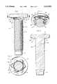
- FIG. 1is a side elevation, partially in section, of a self-clinching fastener in accordance with the present invention
- FIG. 2is a partial perspective view of the fastener of FIG. 1, illustrating the construction of the underside of the head portion;
- FIG. 3is a sectional view taken generally along the line 3--3 of FIG. 1;
- FIG. 4is an axial section through a blank for forming the fastener of FIG. 1;
- FIG. 5is a partial sectional view illustrating formation of a locking ring on the blank of FIG. 4;
- FIG. 6is a partial sectional view illustrating an initial step in the assembly of the fastener of FIG. 1 with a preformed aperture in a sheet material;
- FIG. 7is a partial sectional view similar to FIG. 6, illustrating completion of the assembly of the fastener to the sheet material
- FIG. 8is an enlarged partial view of portion of FIG. 7;
- FIG. 9is a sectional view similar to FIG. 7 and illustrating employment of the present invention in an internally threaded fastener or nut;
- FIG. 10is a side elevation of a second embodiment of a fastener in accordance with the present invention.
- FIG. 11is a sectional view taken generally along the line 11--11 of FIG. 10;
- FIG. 12is an axial sectional view, similar to FIG. 7, with the fastener being viewed generally along the line 12--12 of FIG. 11;
- FIG. 13is an axial sectional view, similar to FIG. 7, with the fastener being viewed generally along the line 13--13 of FIG. 11.
- a staked or self-clinching fastener of the type for connection to a section of sheet material in accordance with the inventionis designated generally by the reference numeral 10.
- the fastener 10includes an enlarged diameter head portion 12 and an elongated shank portion 14 of smaller outer diameter than the outer diameter of the head 12, which projects generally centrally axially from the head 12.
- the shank portion 14is formed with an external screw type thread 16.
- the thread 16terminates at an outer end of the shank 14 in a series of truncated or reduced diameter threads leading to a short, unthreaded lead-in portion 18.
- the inventionalso applies to an internally threaded or nut type of fastener.
- a fasteneris shown in FIG. 9.
- a displacement portion 22extends axially from the underside of the head and is radially spaced from and surrounds the shank 14.
- This displacement portion 22has projections 24 which extend radially outwardly from the shank 14.
- these projections or displacement lugs 24preferably comprise a first series of radially outwardly curved or convex surfaces 24.
- a second series of oppositely, that is, radially inwardly curved or concave surfaces 26merge smoothly with the first series of surfaces 24.
- the first series and second serieseach comprise a total of six (6) curved surfaces, such that the overall configuration is hexlobular while the centers of the first series of surfaces generally define a regular hexagon.
- the particular design or configuration of these surfaces 24 and 26is preferably as illustrated and described in U.S. Pat. No. 3,584,667, which is incorporated herein by reference to this extent.
- an undercut annular groove 20is formed radially inwardly of the displacement portion 22, extending axially toward the underside of the head portion 12, that is, the side from which the shank 14 projects.
- the groovemay be formed in the head portion per se, or in the material which serves to define the displacement portion 22.
- This undercut annular groove 20radially surrounds the shank 14 in the area about which the shank 14 projects from the head 12.
- the undercut annular groove 20is defined at least partially by a generally conical or tapered wall surface 20a which surface converges in the direction of fastener head portion 12.
- a generally opposed, facing conical or tapered surface 20bis defined by the groove 20, which surface is spaced from surface 20a and also converges in the direction of the head 12.
- the axial depth of the groove 20is at least one-half of the axial height of the displacement portion 22, and preferably, equal to or greater than the axial height of the displacement portion 22.
- the outer diameter of the sizing ring 28is greater than the inner diameter of the undercut annular groove 20 and also greater than the outer diameter of the threads 16 on shank 14.
- FIGS. 6-8having described the basic structure of the fastener in accordance with the invention, further features and advantages thereof will be best understood upon consideration of the operation of the fastener in connection with a section of sheet material 30 to which the fastener is to be attached or staked.
- the sheet material 30is provided with a through aperture 32 for receiving a fastener 10.
- the diameter of the aperture 32is preferably equal to or smaller than the outer diameter of the sizing ring 28.
- the relationship of the sizing ring 28 to aperture 32insures that the fastener will displace sufficient material of the sheet 30 about the aperture 32 to fill in the space or volume under the head of the fastener from and including the undercut groove 20 to and including the facing surfaces of the sizing ring 28, as is illustrated for example in FIG. 7.
- the overall volume of the displacement portion 22is designed and selected such as to displace enough material of the sheet 30 upon embedding of the lugs in the material to further assure complete filling of the above-described space with the material of the sheet 30, as illustrated in FIG. 7.
- the tapered surfaces 20a and 20b of groove 20serve to direct the flow of material inwardly and upwardly into the groove 20 at an angle of approximately 45° ⁇ 15°.
- this feature of the inventionalso serves to enhance the overall strength of the joint attained.
- the die 34has an aperture 38 of sufficient diameter for freely receiving the threaded shank 14 therethrough.
- This aperture 38preferably has an enlarged entrance portion 40 of sufficient diameter to freely receive the sizing ring 28 therein when punch 36 has fully advanced the fastener 10 relative to the sheet 30 and die 34.
- the fastener 10' of FIG. 9is similar in structure to the fastener 10 described above in that it includes an enlarged head 12', a projecting, although relatively short, shank 14', displacement portion 22', an undercut annular groove 20', and a sizing ring 28'.
- the groove 20', displacement portion 22' and sizing ring 28are identical to those described hereinabove.
- the fastener 10'is a nut type fastener having an internal central through bore or opening 42 which is internally threaded as indicated by reference numeral 44.
- the clinching or coupling of the fastener 10' with the sheet material 30is the same as illustrated and described hereinabove with respect to the externally threaded screw type fastener 10.
- the degree or strength of the mechanical connection between the fastener 10 and sheet material 30is dependent upon the shear area achieved by the mechanical interlock.
- the shear areais generally defined as the cross-sectional area of the material displaced into the annular undercut groove 20 taken in the direction of shearing, that is, axially, including the volume or space between the surfaces 20a and 20b.
- An increase in shear areain turn translates into a performance increase in pushout strength.
- the tapered surfaces 20a and 20b of the groove 20have directed the flow of material upwardly into the groove 20, assuring that the entire groove is filled.
- an extruding force 50 and its respective vertical or axial and horizontal or radial components 52, 54are indicated generally by arrows in FIG. 8. That is, the material must follow a somewhat tortuous route in extruding back outwardly of the undercut groove 20 and the volume or space between the surfaces 20a and 20b.
- the annular opening into the groove 20 indicated by the dotted line 21 in FIG. 8provides a choke location through which material must flow, and the flow is resisted due to the direction change through which the material 30 must go in order to flow out of the groove 20.
- the pushout performanceis believed improved with the present invention over that realized with prior art clinch-type fasteners, as for example the type shown in the above-mentioned U.S. Pat. No. 3,967,669.
- the fastener of the inventioncan be relatively simply and inexpensively formed from conventional materials by relatively few and simple operations, making the fastener of the invention relatively economical to produce in quantity.
- FIG. 4there is illustrated a blank 10b, ready for further cold forming to form the sizing ring 28 and thread rolling to form the external thread 16 on the shank 14.
- an external thread 16the formation of an internally threaded or nut type fastener such as the fastener 10a shown in FIG. 9 will be substantially identical to the formation of the externally threaded screw type fastener 10.
- the fastenermay be initially formed by cold forming or heading operations on a generally elongate cylindrical piece of material which forms the shank 14.
- the tapered lead-in portion 18can also be cold formed on the blank 10b.
- the head 12is formed, such that the shank 14 projects centrally axially therefrom.
- the partis further provided with an increased diameter shoulder portion 14b of the shank 14 extending a preselected distance axially outwardly from the head 12.
- the annular undercut groove 20is formed by heading the displacement portion 22 in such a manner as to leave this annular undercut groove area 20 at a radially inner part of the displacement portion 22 and immediately adjacent to (i.e., radially outwardly of), and surrounding the enlarged diameter shank portion 14b.
- the formation of the displacement portion 22 with the annular undercut groove 20results in a better formation of the vertical or axially extending outer walls 22b of the displacement portion. This results in less angled relief to these surfaces 22b, and gives an overall better engagement and increased resistance to rotational motion when the displacement portion 22 is embedded in the sheet material 30 as illustrated for example in FIG. 7.
- the enlarged diameter shank portion 14bcan then be deformed or upsetted to form the sizing ring 28, for example as indicated in FIG. 5.
- a suitable die 60can be utilized having a through central opening 62 of generally the same diameter as the diameter of the shank 14, that is, of smaller diameter than increased diameter or shoulder portion 14b.
- the material of the section 14bis displaced upwardly to form the sizing ring 28.
- the outer diameter of the sizing ringshould be larger than the outer diameter of the undercut groove 20. This upsetting process can advantageously be done in primary forming of equipment or, if preferred, as a secondary operation.
- the diameter and axial length of shank portion 14bis determined by the amount of material needed to form the sizing ring 28 of the desired size in this fashion.
- the inner diameter of the annular undercut groove 20is preferably somewhat greater than the pitch diameter of the thread 16 when the same is formed on the shank 14. This will occur when the displacement portion 22 and undercut groove 20 are formed about the increased diameter shank portion 14b, prior to formation of the sizing ring 28.
- the outer diameter of the shoulder portion 14bis greater than the pitch diameter of the thread 16.
- thread 16can be formed by a thread rolling operation, for example, following the completion of the heading process and formation of the sizing ring 28 as illustrated and described above with reference to FIGS. 4 and 5.
- Fastener 110has an enlarged diameter head 112 and an elongated shank 114 which projects axially from one side thereof.
- the shank 114is externally threaded as indicated at reference numeral 116.
- the head 112 and shank 114may be internally threaded in the manner shown for example in FIG. 9, without departing from the invention.
- a lead in portion 118is also provided on the shank 114.
- a plurality of projections or displacement lugs 122extend axially from the underside of the head 112 and extend radially outwardly from the shank 114.
- the lugs 122comprise generally rectilinear radially extending elements.
- outer edges of the lugs 122are tapered inwardly as indicated at reference numeral 124.
- these lugsare six in number and are equally angularly spaced about the underside of the head 112.
- the lugs 122terminate or merge at their radially inner ends at a generally annular axially projecting displacement ring 126.
- the displacement ring 126comprises an annular member which projects axially outwardly of the head 112, that is, in the same direction as shank 114. More or fewer such lugs 122 and different angular spacings thereof might be employed without departing from the invention.
- an undercut annular groove 120is formed radially inwardly of the projections 122 and also radially inwardly of the displacement ring 126, and extends axially toward the underside of the head portion 112, that is the side from which the shank 114 projects.
- the displacement portion 22itself serves the same function as the displacement ring 126 which will be discussed further hereinbelow. That is, the undulations 24, 26 in effect form an axially projecting surface which completely surrounds the undercut annular groove 20 in much the same way as the displacement ring 126 completely surrounds the undercut annular groove 120 of the embodiment of FIGS. 10-13.
- the axial depth of the undercut groove 120is at least one-half of the axial height of the lugs 122, and preferably, is equal or greater than this axial height.
- the groove 120is defined at least partially by a generally conical or tapered wall surface 120a which converges in the direction of the fastener head portion 12 and a generally opposed, facing conical or tapered surface 120b which is spaced from the surface 120a and also converges in the direction of the head 12. It will be noted that surface 120a curves inwardly from the radially outermost part or surface of the sizing ring 128 whereas the surface 120b curves inwardly from a radially inner edge or surface of the displacement ring 126.
- the sizing ring 128is similar to the sizing ring 28 of the embodiments of FIGS. 1-9.
- the sizing ring 128forms an enlarged diameter, generally annular extruding member which is axially spaced from the projections 122 along the shank 114. That is, the sizing ring 128 is axially spaced from the underside of the head 112 by an amount somewhat greater than the axial extent or height of the projections 122.
- the outer diameter of the sizing ring 128is greater than the inner diameter of the undercut annular groove 120 and also greater than the outer diameter of the threads 116 on the shank 114.
- the form of the fastener as shown in FIGS. 10-13displaces less material overall than the fastener as shown in FIGS. 1-8, and is therefore preferable for employment with certain materials such as cast iron, cast aluminum, cast zinc and other materials having a relatively low modulus of elasticity.
- the embodiments of the fastener as shown in FIGS. 1-9would preferably be employed with materials having a somewhat higher modulus of elasticity or somewhat more malleable materials.
- the material displaced into the undercut annular groove 120will be caused to flow in a generally upward and inward direction, that is at an angle of approximately 45° ⁇ 15° relative to the axial direction of the shank 114.
- the material in the groove 120will resist being forced back outwardly of the groove 120, which will require axial and radial movement of the material in generally the opposite angular direction as the above-described flow of material being introduced to the groove 120 upon embedding of the fastener in a workpiece.
- pushout forceswill be effectively resisted by the displacement of material in this regard.
Landscapes
- Engineering & Computer Science (AREA)
- General Engineering & Computer Science (AREA)
- Mechanical Engineering (AREA)
- Insertion Pins And Rivets (AREA)
Abstract
Description
Claims (29)
Priority Applications (2)
| Application Number | Priority Date | Filing Date | Title |
|---|---|---|---|
| US08/222,457US5513933A (en) | 1994-04-04 | 1994-04-04 | Staked fastener with undercut |
| PCT/US1995/003840WO1995027147A1 (en) | 1994-04-04 | 1995-03-28 | Staked fastener with undercut |
Applications Claiming Priority (1)
| Application Number | Priority Date | Filing Date | Title |
|---|---|---|---|
| US08/222,457US5513933A (en) | 1994-04-04 | 1994-04-04 | Staked fastener with undercut |
Publications (1)
| Publication Number | Publication Date |
|---|---|
| US5513933Atrue US5513933A (en) | 1996-05-07 |
Family
ID=22832291
Family Applications (1)
| Application Number | Title | Priority Date | Filing Date |
|---|---|---|---|
| US08/222,457Expired - LifetimeUS5513933A (en) | 1994-04-04 | 1994-04-04 | Staked fastener with undercut |
Country Status (1)
| Country | Link |
|---|---|
| US (1) | US5513933A (en) |
Cited By (46)
| Publication number | Priority date | Publication date | Assignee | Title |
|---|---|---|---|---|
| US5743691A (en)* | 1997-02-03 | 1998-04-28 | Textron Inc. | Clinch-type fastener member |
| US5797175A (en)* | 1992-07-07 | 1998-08-25 | Richard Bergner Gmbh & Co. | Process for connecting an insert to a sheet to form a joint designed to be secured against rotation and insert ejection |
| US6309156B1 (en)* | 1994-02-01 | 2001-10-30 | Richard Bergner Gmbh & Co. | Mounting unit and method of making same |
| US6318940B1 (en) | 2000-06-21 | 2001-11-20 | Illinois Tool Works Inc. | Fastener for self-locking securement within a panel opening |
| WO2003008817A1 (en)* | 2001-07-19 | 2003-01-30 | Fabristeel Products, Inc. | Locating pin on double ended stud |
| US6647608B2 (en) | 2001-07-19 | 2003-11-18 | Fabristeel Products, Inc. | Method of installing a fastener |
| US20040031551A1 (en)* | 2001-07-19 | 2004-02-19 | Wojciechowski Stanley E. | Fastener, method of attaching a fastener to a panel and fastener and panel assembly |
| US6817815B2 (en) | 2000-07-12 | 2004-11-16 | Textron Verbindungstechnik Gmbh & Co., Ltd. | Fastener being pressable into a metal sheet in a way safe against rotation and pressing out |
| US6832882B2 (en) | 2001-10-05 | 2004-12-21 | Illinois Tool Works Inc. | Fastener |
| US20060002781A1 (en)* | 2004-06-21 | 2006-01-05 | Robert Mangapora | Captive fastener |
| US20060174261A1 (en)* | 2004-11-19 | 2006-08-03 | Image Impact, Inc. | Method and system for quantifying viewer awareness of advertising images in a video source |
| US20060204348A1 (en)* | 2005-03-08 | 2006-09-14 | Shuart David M | Self-attaching fastener and fastener and panel assembly |
| US20060265856A1 (en)* | 2001-07-19 | 2006-11-30 | Parker John M | Method of attaching a clinch spacer to a panel |
| US20070098520A1 (en)* | 2004-01-13 | 2007-05-03 | Thorsten Schraer | Bolt that can be pressed into a metal sheet in a torsion-proof and ejection-proof manner |
| US20080120825A1 (en)* | 2001-07-19 | 2008-05-29 | Shuart David M | Clinch spacer and method of attaching the same to a panel |
| US20090162135A1 (en)* | 2004-10-15 | 2009-06-25 | Egbert Frenken | Cable lug comprising a nut or functional part, method for the production of such a cable lug, and nut |
| US20100074712A1 (en)* | 2008-09-19 | 2010-03-25 | Pias Sales Co., Ltd. | Clinch bolt |
| US7878746B2 (en)* | 2003-11-17 | 2011-02-01 | Profil Verbindungstechnik Gmbh & Co. Kg | Functional element, assembling component consisting of the functional element combined with a metal sheet, method for producing the assembly component and method for producing the functional element |
| US20120003059A1 (en)* | 2010-06-30 | 2012-01-05 | Pias Sales Co., Ltd. | Clinch bolt |
| US8096743B2 (en)* | 2007-07-26 | 2012-01-17 | Profil Verbindungstechnik Gmbh & Co., Kg | Press-in element for pressing into a non-pierced or pierced component and also method for the manufacture of the press-in element |
| US20120189402A1 (en)* | 2011-01-20 | 2012-07-26 | Jiri Babej | Functional element in the form of a press-in element |
| DE102011104529A1 (en)* | 2011-06-18 | 2012-12-20 | Nedschroef Altena Gmbh | Insertion bolt e.g. insertion screw, for pressing into prepunched sheet metal part, has insertion rib formed on annular surface concentric to threaded bolt, and barrier ribs running outward from insertion rib and arranged on surface |
| US20130022782A1 (en)* | 2011-07-21 | 2013-01-24 | Jiri Babej | Functional element having features providing security against rotation and also a component assembly consisting of the functional element and a sheet metal part |
| DE102012001086A1 (en)* | 2012-01-20 | 2013-07-25 | Profil Verbindungstechnik Gmbh & Co. Kg | Bolt element and method for attaching a bolt element to a component made of a composite material |
| US20130259597A1 (en)* | 2008-02-22 | 2013-10-03 | Newfrey Llc | Weld stud |
| US20140003883A1 (en)* | 2012-06-29 | 2014-01-02 | Infastech Intellectual Properties Pte. Ltd. | Self-clinching fastener |
| US8939689B2 (en) | 2012-03-27 | 2015-01-27 | Profil Verbindungstechnik Gmbh & Co. Kg | Functional element in the form of a press-in element |
| DE102013013368A1 (en)* | 2013-08-13 | 2015-02-19 | Lisa Dräxlmaier GmbH | Method for producing an electrical connection and electrical connection |
| US8979455B2 (en) | 2011-11-07 | 2015-03-17 | Rifast Systems Llc | Clinch fastener |
| WO2017019912A3 (en)* | 2015-07-28 | 2017-03-09 | Penn Engineering & Manufacturing Corp. | Tapered head clinch fastener |
| US9682464B2 (en) | 2010-07-07 | 2017-06-20 | Infastech Intellectual Properties Pte Ltd | Torque transmission driver |
| JP2017155860A (en)* | 2016-03-02 | 2017-09-07 | 株式会社青山製作所 | Caulking bolt |
| JP2019002541A (en)* | 2017-06-19 | 2019-01-10 | イワタボルト株式会社 | Fastening bolt |
| WO2020146450A1 (en) | 2019-01-08 | 2020-07-16 | Acument Intellectual Properties, Llc | Clinch fastener |
| WO2021009608A1 (en)* | 2019-07-15 | 2021-01-21 | Garlati Stefano | Fastening element |
| US10960503B2 (en) | 2017-12-07 | 2021-03-30 | Rifast Systems Llc | Staked installation method |
| US10968939B2 (en) | 2011-08-25 | 2021-04-06 | Infastech Intellectual Properties Pte. Ltd. | Tapered lobular driver and fastener |
| US11215215B2 (en) | 2011-08-25 | 2022-01-04 | Infastech Intellectual Properties Pte. Ltd. | Tapered lobular driver and fastener |
| CN114135560A (en)* | 2021-11-30 | 2022-03-04 | Oppo广东移动通信有限公司 | Fastener and electronic device |
| WO2022123805A1 (en)* | 2020-12-08 | 2022-06-16 | 日東精工株式会社 | Stud bolt |
| US20220235805A1 (en)* | 2021-01-05 | 2022-07-28 | Profil Verbindungstechnik Gmbh & Co. Kg | Functional Element, Component Assembly and Method of Manufacturing a Component Assembly |
| US11703076B2 (en)* | 2018-07-06 | 2023-07-18 | Penn Engineering & Manufacturing Corp. | Clinch fastener with a spiral shank |
| US20230235773A1 (en)* | 2019-01-08 | 2023-07-27 | Acument Intellectual Properties, Llc | Clinch fastener |
| DE102013022354B3 (en) | 2013-08-13 | 2024-02-22 | Lisa Dräxlmaier GmbH | Method for establishing an electrical connection and electrical connection |
| DE102024103111A1 (en) | 2023-02-06 | 2024-08-08 | Aoyama Seisakusho Co., Ltd. | FASTENING ELEMENT |
| EP4617512A1 (en) | 2024-03-15 | 2025-09-17 | Böllhoff Verbindungstechnik GmbH | Self-piercing metal fastening sleeve, first component having the fastening sleeve, connection structure having the first component, and method for setting the fastening sleeve |
Citations (9)
| Publication number | Priority date | Publication date | Assignee | Title |
|---|---|---|---|---|
| US3133579A (en)* | 1960-11-10 | 1964-05-19 | Kaynar Mfg Co | Self-staking fastener having alternate teeth and lands |
| US3253631A (en)* | 1963-06-17 | 1966-05-31 | Republic Steel Corp | Cold-formed self-piercing nut |
| US3399705A (en)* | 1966-02-10 | 1968-09-03 | Lamson & Sessions Co | Self-staking insert |
| US3584667A (en)* | 1966-09-19 | 1971-06-15 | Textron Inc | Coupling arrangement and tools for same |
| US3736969A (en)* | 1966-09-22 | 1973-06-05 | H Warn | Pierce nut |
| US3967669A (en)* | 1974-05-06 | 1976-07-06 | Textron, Inc. | Clinch type fastener |
| US4543023A (en)* | 1981-05-28 | 1985-09-24 | Russell, Burdsall & Ward Corporation | Fastener |
| US4637766A (en)* | 1985-06-17 | 1987-01-20 | Textron Inc. | Clinch type fastener |
| WO1994001688A1 (en)* | 1992-07-07 | 1994-01-20 | Richard Bergner Gmbh & Co. | Insert for use as a connection element for joints designed to be secure against rotation and insert ejection |
- 1994
- 1994-04-04USUS08/222,457patent/US5513933A/ennot_activeExpired - Lifetime
Patent Citations (9)
| Publication number | Priority date | Publication date | Assignee | Title |
|---|---|---|---|---|
| US3133579A (en)* | 1960-11-10 | 1964-05-19 | Kaynar Mfg Co | Self-staking fastener having alternate teeth and lands |
| US3253631A (en)* | 1963-06-17 | 1966-05-31 | Republic Steel Corp | Cold-formed self-piercing nut |
| US3399705A (en)* | 1966-02-10 | 1968-09-03 | Lamson & Sessions Co | Self-staking insert |
| US3584667A (en)* | 1966-09-19 | 1971-06-15 | Textron Inc | Coupling arrangement and tools for same |
| US3736969A (en)* | 1966-09-22 | 1973-06-05 | H Warn | Pierce nut |
| US3967669A (en)* | 1974-05-06 | 1976-07-06 | Textron, Inc. | Clinch type fastener |
| US4543023A (en)* | 1981-05-28 | 1985-09-24 | Russell, Burdsall & Ward Corporation | Fastener |
| US4637766A (en)* | 1985-06-17 | 1987-01-20 | Textron Inc. | Clinch type fastener |
| WO1994001688A1 (en)* | 1992-07-07 | 1994-01-20 | Richard Bergner Gmbh & Co. | Insert for use as a connection element for joints designed to be secure against rotation and insert ejection |
Non-Patent Citations (2)
| Title |
|---|
| RIMS, D 91126 Schwabach, Bahnhofstrasse S 16, RIMS , Automatisierte Verbindungstechnik in Blechen, covers and pp. 1 9, drawings nos. 7191w, SK1668, and translation of pp. 1 9, Richard Bergner GmbH & Co., 1994.* |
| RIMS, D-91126 Schwabach, Bahnhofstrasse S-16, RIMS®, Automatisierte Verbindungstechnik in Blechen, covers and pp. 1-9, drawings nos. 7191w, SK1668, and translation of pp. 1-9, Richard Bergner GmbH & Co., 1994. |
Cited By (78)
| Publication number | Priority date | Publication date | Assignee | Title |
|---|---|---|---|---|
| US5797175A (en)* | 1992-07-07 | 1998-08-25 | Richard Bergner Gmbh & Co. | Process for connecting an insert to a sheet to form a joint designed to be secured against rotation and insert ejection |
| US6309156B1 (en)* | 1994-02-01 | 2001-10-30 | Richard Bergner Gmbh & Co. | Mounting unit and method of making same |
| US5743691A (en)* | 1997-02-03 | 1998-04-28 | Textron Inc. | Clinch-type fastener member |
| AU721145B2 (en)* | 1997-02-03 | 2000-06-22 | Acument Intellectual Properties, Llc | Clinch-type fastener member |
| US6318940B1 (en) | 2000-06-21 | 2001-11-20 | Illinois Tool Works Inc. | Fastener for self-locking securement within a panel opening |
| US6817815B2 (en) | 2000-07-12 | 2004-11-16 | Textron Verbindungstechnik Gmbh & Co., Ltd. | Fastener being pressable into a metal sheet in a way safe against rotation and pressing out |
| US6647608B2 (en) | 2001-07-19 | 2003-11-18 | Fabristeel Products, Inc. | Method of installing a fastener |
| US20040031551A1 (en)* | 2001-07-19 | 2004-02-19 | Wojciechowski Stanley E. | Fastener, method of attaching a fastener to a panel and fastener and panel assembly |
| US7124492B2 (en) | 2001-07-19 | 2006-10-24 | Whitesell International Corporation | Fastener, method of attaching a fastener to a panel and fastener and panel assembly |
| WO2003008817A1 (en)* | 2001-07-19 | 2003-01-30 | Fabristeel Products, Inc. | Locating pin on double ended stud |
| EP1417419A4 (en)* | 2001-07-19 | 2005-03-30 | Fabristeel Prod Inc | Locating pin on double ended stud |
| US8092131B2 (en) | 2001-07-19 | 2012-01-10 | Whitesell International Corporation | Clinch spacer and method of attaching the same to a panel |
| US7698799B2 (en) | 2001-07-19 | 2010-04-20 | Whitesell International Corporation | Method of attaching a clinch spacer to a panel |
| US20080120825A1 (en)* | 2001-07-19 | 2008-05-29 | Shuart David M | Clinch spacer and method of attaching the same to a panel |
| US20060265856A1 (en)* | 2001-07-19 | 2006-11-30 | Parker John M | Method of attaching a clinch spacer to a panel |
| US20060218769A1 (en)* | 2001-07-19 | 2006-10-05 | Wojciechowski Stanley E | Fastener, method of attaching a fastener to a panel and fastener and panel assembly |
| US6832882B2 (en) | 2001-10-05 | 2004-12-21 | Illinois Tool Works Inc. | Fastener |
| WO2005017370A3 (en)* | 2003-08-13 | 2005-12-29 | Fabristeel Prod Inc | Fastener, method of attaching a fastener to a panel and fastener and panel assembly |
| EP1660273A4 (en)* | 2003-08-13 | 2010-03-31 | Whitesell Int Corp | Fastener, method of attaching a fastener to a panel and fastener and panel assembly |
| US7878746B2 (en)* | 2003-11-17 | 2011-02-01 | Profil Verbindungstechnik Gmbh & Co. Kg | Functional element, assembling component consisting of the functional element combined with a metal sheet, method for producing the assembly component and method for producing the functional element |
| US20110097173A1 (en)* | 2003-11-17 | 2011-04-28 | Profil Verbindungstechnik Gmbh & Co., Kg | Functional element, component assembly comprising the functional element in combination with a sheet metal part, method for the manufacture of a component assembly and also method for the manufacture of the functional element |
| US8517651B2 (en)* | 2003-11-17 | 2013-08-27 | Profil Verbindungstechnik Gmbh & Co., Kg | Functional element, component assembly comprising the functional element in combination with a sheet metal part, method for the manufacture of a component assembly and also method for the manufacture of the functional element |
| US20070098520A1 (en)* | 2004-01-13 | 2007-05-03 | Thorsten Schraer | Bolt that can be pressed into a metal sheet in a torsion-proof and ejection-proof manner |
| US20060002781A1 (en)* | 2004-06-21 | 2006-01-05 | Robert Mangapora | Captive fastener |
| US9735478B2 (en) | 2004-10-15 | 2017-08-15 | Gustav Klauke Gmbh | Cable lug comprising a nut or functional part, method for the production of such a cable lug, and nut |
| US20090162135A1 (en)* | 2004-10-15 | 2009-06-25 | Egbert Frenken | Cable lug comprising a nut or functional part, method for the production of such a cable lug, and nut |
| US8777536B2 (en)* | 2004-10-15 | 2014-07-15 | Gustav Klauke Gmbh | Cable lug comprising a nut or functional part, method for the production of such a cable lug, and nut |
| US20060174261A1 (en)* | 2004-11-19 | 2006-08-03 | Image Impact, Inc. | Method and system for quantifying viewer awareness of advertising images in a video source |
| US20060204348A1 (en)* | 2005-03-08 | 2006-09-14 | Shuart David M | Self-attaching fastener and fastener and panel assembly |
| US8096743B2 (en)* | 2007-07-26 | 2012-01-17 | Profil Verbindungstechnik Gmbh & Co., Kg | Press-in element for pressing into a non-pierced or pierced component and also method for the manufacture of the press-in element |
| US20120102712A1 (en)* | 2007-07-26 | 2012-05-03 | Profil Verbindungstechnik Gmbh & Co., Kg | Press-in element for pressing into a non-pierced or pierced component and also method for the manufacture of the press-in element |
| US8898882B2 (en)* | 2007-07-26 | 2014-12-02 | Profil Verbindungstechnik Gmbh & Co., Kg | Press-in element for pressing into a non-pierced or pierced component and also method for the manufacture of the press-in element |
| US8998549B2 (en)* | 2008-02-22 | 2015-04-07 | Newfrey Llc | Weld stud |
| US20130259597A1 (en)* | 2008-02-22 | 2013-10-03 | Newfrey Llc | Weld stud |
| US20100074712A1 (en)* | 2008-09-19 | 2010-03-25 | Pias Sales Co., Ltd. | Clinch bolt |
| US20120003059A1 (en)* | 2010-06-30 | 2012-01-05 | Pias Sales Co., Ltd. | Clinch bolt |
| US10022844B2 (en) | 2010-07-07 | 2018-07-17 | Infastech Intellectual Properties Pte. Ltd. | Torque transmission driver |
| US9815180B2 (en) | 2010-07-07 | 2017-11-14 | Infastech Intellectual Properties, PTE. LTD. | Torque transmission driver |
| US9682464B2 (en) | 2010-07-07 | 2017-06-20 | Infastech Intellectual Properties Pte Ltd | Torque transmission driver |
| US8734071B2 (en)* | 2011-01-20 | 2014-05-27 | Profil-Verbindungstechnik Gmbh & Co. Kg | Functional element in the form of a press-in element |
| US20120189402A1 (en)* | 2011-01-20 | 2012-07-26 | Jiri Babej | Functional element in the form of a press-in element |
| JP2012149766A (en)* | 2011-01-20 | 2012-08-09 | Profil Verbindungstechnik Gmbh & Co Kg | Functional element, component assembly, and method for manufacturing functional element |
| DE102011104529A1 (en)* | 2011-06-18 | 2012-12-20 | Nedschroef Altena Gmbh | Insertion bolt e.g. insertion screw, for pressing into prepunched sheet metal part, has insertion rib formed on annular surface concentric to threaded bolt, and barrier ribs running outward from insertion rib and arranged on surface |
| US20130022782A1 (en)* | 2011-07-21 | 2013-01-24 | Jiri Babej | Functional element having features providing security against rotation and also a component assembly consisting of the functional element and a sheet metal part |
| US9175715B2 (en)* | 2011-07-21 | 2015-11-03 | Profil Verbindungstechnik Gmbh & Co. Kg | Functional element having features providing security against rotation and also a component assembly consisting of the functional element and a sheet metal part |
| US10968939B2 (en) | 2011-08-25 | 2021-04-06 | Infastech Intellectual Properties Pte. Ltd. | Tapered lobular driver and fastener |
| US11215215B2 (en) | 2011-08-25 | 2022-01-04 | Infastech Intellectual Properties Pte. Ltd. | Tapered lobular driver and fastener |
| US9574602B2 (en) | 2011-11-07 | 2017-02-21 | Rifast Systems Llc | Clinch fastener |
| US8979455B2 (en) | 2011-11-07 | 2015-03-17 | Rifast Systems Llc | Clinch fastener |
| US9297405B2 (en) | 2012-01-20 | 2016-03-29 | Profil Verbindungstechnik Gmbh & Co., Kg | Bolt element and a method for the attachment of a bolt element to a component of a composite material |
| DE102012001086A1 (en)* | 2012-01-20 | 2013-07-25 | Profil Verbindungstechnik Gmbh & Co. Kg | Bolt element and method for attaching a bolt element to a component made of a composite material |
| US8939689B2 (en) | 2012-03-27 | 2015-01-27 | Profil Verbindungstechnik Gmbh & Co. Kg | Functional element in the form of a press-in element |
| US20140003883A1 (en)* | 2012-06-29 | 2014-01-02 | Infastech Intellectual Properties Pte. Ltd. | Self-clinching fastener |
| US9400005B2 (en)* | 2012-06-29 | 2016-07-26 | Infastech Intellectual Property Pte. Ltd | Self-clinching fastener |
| TWI613371B (en)* | 2012-06-29 | 2018-02-01 | 殷費帝克智財專賣有限公司 | Self-clinching fastener |
| DE102013022354B3 (en) | 2013-08-13 | 2024-02-22 | Lisa Dräxlmaier GmbH | Method for establishing an electrical connection and electrical connection |
| DE102013013368A1 (en)* | 2013-08-13 | 2015-02-19 | Lisa Dräxlmaier GmbH | Method for producing an electrical connection and electrical connection |
| DE102013013368B4 (en)* | 2013-08-13 | 2020-03-05 | Lisa Dräxlmaier GmbH | Method for establishing an electrical connection and electrical connection |
| US10428847B2 (en) | 2015-07-28 | 2019-10-01 | Pem Management, Inc. | Tapered head clinch fastener |
| WO2017019912A3 (en)* | 2015-07-28 | 2017-03-09 | Penn Engineering & Manufacturing Corp. | Tapered head clinch fastener |
| US10655666B2 (en)* | 2016-03-02 | 2020-05-19 | Aoyama Seisakusho Co., Ltd. | Caulking bolt |
| US20180266475A1 (en)* | 2016-03-02 | 2018-09-20 | Aoyama Seisakusho Co., Ltd. | Caulking bolt |
| JP2017155860A (en)* | 2016-03-02 | 2017-09-07 | 株式会社青山製作所 | Caulking bolt |
| JP2019002541A (en)* | 2017-06-19 | 2019-01-10 | イワタボルト株式会社 | Fastening bolt |
| US10960503B2 (en) | 2017-12-07 | 2021-03-30 | Rifast Systems Llc | Staked installation method |
| US11703076B2 (en)* | 2018-07-06 | 2023-07-18 | Penn Engineering & Manufacturing Corp. | Clinch fastener with a spiral shank |
| US11614118B2 (en) | 2019-01-08 | 2023-03-28 | Acument Intellectual Properties, Llc | Clinch fastener |
| US20230235773A1 (en)* | 2019-01-08 | 2023-07-27 | Acument Intellectual Properties, Llc | Clinch fastener |
| WO2020146450A1 (en) | 2019-01-08 | 2020-07-16 | Acument Intellectual Properties, Llc | Clinch fastener |
| WO2021009608A1 (en)* | 2019-07-15 | 2021-01-21 | Garlati Stefano | Fastening element |
| WO2022123805A1 (en)* | 2020-12-08 | 2022-06-16 | 日東精工株式会社 | Stud bolt |
| JP2022090935A (en)* | 2020-12-08 | 2022-06-20 | 日東精工株式会社 | Stud |
| JP7106621B2 (en) | 2020-12-08 | 2022-07-26 | 日東精工株式会社 | Stud |
| US20220235805A1 (en)* | 2021-01-05 | 2022-07-28 | Profil Verbindungstechnik Gmbh & Co. Kg | Functional Element, Component Assembly and Method of Manufacturing a Component Assembly |
| CN114135560A (en)* | 2021-11-30 | 2022-03-04 | Oppo广东移动通信有限公司 | Fastener and electronic device |
| DE102024103111A1 (en) | 2023-02-06 | 2024-08-08 | Aoyama Seisakusho Co., Ltd. | FASTENING ELEMENT |
| EP4617512A1 (en) | 2024-03-15 | 2025-09-17 | Böllhoff Verbindungstechnik GmbH | Self-piercing metal fastening sleeve, first component having the fastening sleeve, connection structure having the first component, and method for setting the fastening sleeve |
| WO2025190520A1 (en) | 2024-03-15 | 2025-09-18 | Böllhoff Verbindungstechnik GmbH | Self-piercing metal fastening sleeve, first component having the fastening sleeve, connecting structure having the first component, and method for setting the fastening sleeve |
Similar Documents
| Publication | Publication Date | Title |
|---|---|---|
| US5513933A (en) | Staked fastener with undercut | |
| US3967669A (en) | Clinch type fastener | |
| US4637766A (en) | Clinch type fastener | |
| CA2286946C (en) | Self-piercing clinch nut | |
| US5531552A (en) | Self-attaching nut and method of making same | |
| US6994500B2 (en) | Self-attaching nut | |
| US7597515B2 (en) | Self-attaching nut | |
| US6231286B1 (en) | Headed fastener with precisely calculated groove under head to accommodate O'ring sealing member as a self-sealing assembly | |
| US6261040B1 (en) | Self-tapping fastener | |
| US7425111B2 (en) | Torque resistant fastening element | |
| US3927503A (en) | Prevailing torque fastener | |
| US6439818B1 (en) | Nut and intermediate product therefor | |
| US4768908A (en) | Self-locking screw - nut assembly | |
| US20020172573A1 (en) | Self-piercing clinch nut | |
| WO1995027147A1 (en) | Staked fastener with undercut | |
| US3842710A (en) | Removable rivet | |
| US4806054A (en) | Male threaded fastener capable of use with a swaged collar | |
| GB2088508A (en) | Bolt heads and nuts | |
| US3491646A (en) | Fastening means for a rotational fastener and method | |
| US4370794A (en) | Clinch nut and method of installing same | |
| US3029856A (en) | Lock nut with displaced thread portion | |
| US4381163A (en) | Self-locking nut | |
| US7112142B2 (en) | Method of cold forming a self-attaching female fastener element | |
| GB2041135A (en) | Self-locking nut | |
| US20050271495A1 (en) | Self-attaching female fastener, die set and method of attachment |
Legal Events
| Date | Code | Title | Description |
|---|---|---|---|
| AS | Assignment | Owner name:TEXTRON INC., RHODE ISLAND Free format text:ASSIGNMENT OF ASSIGNORS INTEREST;ASSIGNOR:ROM, RONALD R.;REEL/FRAME:006979/0449 Effective date:19940328 | |
| STCF | Information on status: patent grant | Free format text:PATENTED CASE | |
| FEPP | Fee payment procedure | Free format text:PAYOR NUMBER ASSIGNED (ORIGINAL EVENT CODE: ASPN); ENTITY STATUS OF PATENT OWNER: LARGE ENTITY | |
| FPAY | Fee payment | Year of fee payment:4 | |
| FPAY | Fee payment | Year of fee payment:8 | |
| AS | Assignment | Owner name:TEXTRON IPMP L.P., MICHIGAN Free format text:ASSIGNMENT OF ASSIGNORS INTEREST;ASSIGNORS:TEXTRON INC.;TEXTRON MICHIGAN INC.;REEL/FRAME:015156/0266 Effective date:20010401 | |
| AS | Assignment | Owner name:ACUMENT INTELLECTUAL PROPERTIES LLC, MICHIGAN Free format text:ASSIGNMENT OF ASSIGNORS INTEREST;ASSIGNORS:TEXTRON INC.;TEXTRON INNOVATIONS INC.;AVDEL CHERRY RHODE ISLAND INC.;AND OTHERS;REEL/FRAME:018767/0300 Effective date:20061027 Owner name:ACUMENT INTELLECTUAL PROPERTIES LLC,MICHIGAN Free format text:ASSIGNMENT OF ASSIGNORS INTEREST;ASSIGNORS:TEXTRON INC.;TEXTRON INNOVATIONS INC.;AVDEL CHERRY RHODE ISLAND INC.;AND OTHERS;REEL/FRAME:018767/0300 Effective date:20061027 | |
| FPAY | Fee payment | Year of fee payment:12 | |
| REMI | Maintenance fee reminder mailed | ||
| AS | Assignment | Owner name:WILMINGTON TRUST FSB, AS COLLATERAL AGENT, NEW YOR Free format text:SECURITY AGREEMENT;ASSIGNOR:ACUMENT INTELLECTUAL PROPERTIES, LLC;REEL/FRAME:023273/0114 Effective date:20090901 Owner name:WILMINGTON TRUST FSB, AS COLLATERAL AGENT,NEW YORK Free format text:SECURITY AGREEMENT;ASSIGNOR:ACUMENT INTELLECTUAL PROPERTIES, LLC;REEL/FRAME:023273/0114 Effective date:20090901 | |
| AS | Assignment | Owner name:WELLS FARGO FOOTHILL, INC., AS COLLATERAL AGENT, C Free format text:SECURITY AGREEMENT;ASSIGNOR:ACUMENT INTELLECTUAL PROPERTIES, LLC;REEL/FRAME:023273/0875 Effective date:20090901 Owner name:WELLS FARGO FOOTHILL, INC., AS COLLATERAL AGENT,CA Free format text:SECURITY AGREEMENT;ASSIGNOR:ACUMENT INTELLECTUAL PROPERTIES, LLC;REEL/FRAME:023273/0875 Effective date:20090901 | |
| AS | Assignment | Owner name:SATURN FASTENERS, INC., MICHIGAN Free format text:RELEASE OF PATENT SECURITY INTEREST;ASSIGNOR:WILMINGTON TRUST FSB, AS THE AGENT;REEL/FRAME:024776/0651 Effective date:20100803 Owner name:ACUMENT INTELLECTUAL PROPERTIES, LLC, MICHIGAN Free format text:RELEASE OF PATENT SECURITY INTEREST;ASSIGNOR:WILMINGTON TRUST FSB, AS THE AGENT;REEL/FRAME:024776/0651 Effective date:20100803 Owner name:KING HOLDING CORPORATION, MICHIGAN Free format text:RELEASE OF PATENT SECURITY INTEREST;ASSIGNOR:WILMINGTON TRUST FSB, AS THE AGENT;REEL/FRAME:024776/0651 Effective date:20100803 Owner name:FLEXALLOY, INC., MICHIGAN Free format text:RELEASE OF PATENT SECURITY INTEREST;ASSIGNOR:WILMINGTON TRUST FSB, AS THE AGENT;REEL/FRAME:024776/0651 Effective date:20100803 Owner name:RING SCREW LLC, MICHIGAN Free format text:RELEASE OF PATENT SECURITY INTEREST;ASSIGNOR:WILMINGTON TRUST FSB, AS THE AGENT;REEL/FRAME:024776/0651 Effective date:20100803 Owner name:ACUMENT GLOBAL TECHNOLOGIES, INC., MICHIGAN Free format text:RELEASE OF PATENT SECURITY INTEREST;ASSIGNOR:WILMINGTON TRUST FSB, AS THE AGENT;REEL/FRAME:024776/0651 Effective date:20100803 Owner name:WOLVERINE METAL SPECIALTIES, INC., MICHIGAN Free format text:RELEASE OF PATENT SECURITY INTEREST;ASSIGNOR:WILMINGTON TRUST FSB, AS THE AGENT;REEL/FRAME:024776/0651 Effective date:20100803 Owner name:AVDEL USA LLC, MICHIGAN Free format text:RELEASE OF PATENT SECURITY INTEREST;ASSIGNOR:WILMINGTON TRUST FSB, AS THE AGENT;REEL/FRAME:024776/0651 Effective date:20100803 Owner name:KING HOLDING US CORPORATION, MICHIGAN Free format text:RELEASE OF PATENT SECURITY INTEREST;ASSIGNOR:WILMINGTON TRUST FSB, AS THE AGENT;REEL/FRAME:024776/0651 Effective date:20100803 Owner name:ELCO FASTENING SYSTEMS LLC, MICHIGAN Free format text:RELEASE OF PATENT SECURITY INTEREST;ASSIGNOR:WILMINGTON TRUST FSB, AS THE AGENT;REEL/FRAME:024776/0651 Effective date:20100803 Owner name:ACUMENT FASTENING SYSTEMS LLC, MICHIGAN Free format text:RELEASE OF PATENT SECURITY INTEREST;ASSIGNOR:WILMINGTON TRUST FSB, AS THE AGENT;REEL/FRAME:024776/0651 Effective date:20100803 Owner name:CAMCAR LLC, MICHIGAN Free format text:RELEASE OF PATENT SECURITY INTEREST;ASSIGNOR:WILMINGTON TRUST FSB, AS THE AGENT;REEL/FRAME:024776/0651 Effective date:20100803 | |
| AS | Assignment | Owner name:ACUMENT FASTENING SYSTEMS LLC, MICHIGAN Free format text:RELEASE OF SECURITY INTEREST;ASSIGNOR:WELLS FARGO CAPITAL FINANCE, LLC (AS SUCCESSOR BY MERGER TO WELLS FARGO CAPITAL FINANCE, INC. (F/K/A WELLS FARGO FOOTHILL, INC.)), AS COLLATERAL AGENT;REEL/FRAME:033202/0846 Effective date:20140619 Owner name:KING HOLDING US CORPORATION, MICHIGAN Free format text:RELEASE OF SECURITY INTEREST;ASSIGNOR:WELLS FARGO CAPITAL FINANCE, LLC (AS SUCCESSOR BY MERGER TO WELLS FARGO CAPITAL FINANCE, INC. (F/K/A WELLS FARGO FOOTHILL, INC.)), AS COLLATERAL AGENT;REEL/FRAME:033202/0846 Effective date:20140619 Owner name:ACUMENT INTELLECTUAL PROPERTIES, LLC, MICHIGAN Free format text:RELEASE OF SECURITY INTEREST;ASSIGNOR:WELLS FARGO CAPITAL FINANCE, LLC (AS SUCCESSOR BY MERGER TO WELLS FARGO CAPITAL FINANCE, INC. (F/K/A WELLS FARGO FOOTHILL, INC.)), AS COLLATERAL AGENT;REEL/FRAME:033202/0846 Effective date:20140619 Owner name:SATURN FASTENERS, INC., MICHIGAN Free format text:RELEASE OF SECURITY INTEREST;ASSIGNOR:WELLS FARGO CAPITAL FINANCE, LLC (AS SUCCESSOR BY MERGER TO WELLS FARGO CAPITAL FINANCE, INC. (F/K/A WELLS FARGO FOOTHILL, INC.)), AS COLLATERAL AGENT;REEL/FRAME:033202/0846 Effective date:20140619 Owner name:ACUMENT GLOBAL TECHNOLOGIES, INC., MICHIGAN Free format text:RELEASE OF SECURITY INTEREST;ASSIGNOR:WELLS FARGO CAPITAL FINANCE, LLC (AS SUCCESSOR BY MERGER TO WELLS FARGO CAPITAL FINANCE, INC. (F/K/A WELLS FARGO FOOTHILL, INC.)), AS COLLATERAL AGENT;REEL/FRAME:033202/0846 Effective date:20140619 Owner name:KING HOLDING CORPORATION, MICHIGAN Free format text:RELEASE OF SECURITY INTEREST;ASSIGNOR:WELLS FARGO CAPITAL FINANCE, LLC (AS SUCCESSOR BY MERGER TO WELLS FARGO CAPITAL FINANCE, INC. (F/K/A WELLS FARGO FOOTHILL, INC.)), AS COLLATERAL AGENT;REEL/FRAME:033202/0846 Effective date:20140619 Owner name:CAMCAR LLC, MICHIGAN Free format text:RELEASE OF SECURITY INTEREST;ASSIGNOR:WELLS FARGO CAPITAL FINANCE, LLC (AS SUCCESSOR BY MERGER TO WELLS FARGO CAPITAL FINANCE, INC. (F/K/A WELLS FARGO FOOTHILL, INC.)), AS COLLATERAL AGENT;REEL/FRAME:033202/0846 Effective date:20140619 Owner name:RING SCREW LLC, MICHIGAN Free format text:RELEASE OF SECURITY INTEREST;ASSIGNOR:WELLS FARGO CAPITAL FINANCE, LLC (AS SUCCESSOR BY MERGER TO WELLS FARGO CAPITAL FINANCE, INC. (F/K/A WELLS FARGO FOOTHILL, INC.)), AS COLLATERAL AGENT;REEL/FRAME:033202/0846 Effective date:20140619 | |
| AS | Assignment | Owner name:WELLS FARGO BANK, NATIONAL ASSOCIATION, AS ADMINISTRATIVE AGENT, CALIFORNIA Free format text:SECURITY INTEREST;ASSIGNORS:FONTANA AMERICA INCORPORATED;FONTANA FASTENERS, INC.;ACUMENT GLOBAL TECHNOLOGIES, INC.;AND OTHERS;REEL/FRAME:033203/0119 Effective date:20140619 Owner name:WELLS FARGO BANK, NATIONAL ASSOCIATION, AS ADMINIS Free format text:SECURITY INTEREST;ASSIGNORS:FONTANA AMERICA INCORPORATED;FONTANA FASTENERS, INC.;ACUMENT GLOBAL TECHNOLOGIES, INC.;AND OTHERS;REEL/FRAME:033203/0119 Effective date:20140619 | |
| AS | Assignment | Owner name:ACUMENT GLOBAL TECHNOLOGIES, INC., MICHIGAN Free format text:RELEASE BY SECURED PARTY;ASSIGNOR:WELLS FARGO BANK, NATIONAL ASSOCIATION, AS ADMINISTRATIVE AGENT;REEL/FRAME:054387/0155 Effective date:20201030 Owner name:SATURN FASTENERS, INC., MICHIGAN Free format text:RELEASE BY SECURED PARTY;ASSIGNOR:WELLS FARGO BANK, NATIONAL ASSOCIATION, AS ADMINISTRATIVE AGENT;REEL/FRAME:054387/0155 Effective date:20201030 Owner name:ACUMENT INTELLECTUAL PROPERTIES, LLC, MICHIGAN Free format text:RELEASE BY SECURED PARTY;ASSIGNOR:WELLS FARGO BANK, NATIONAL ASSOCIATION, AS ADMINISTRATIVE AGENT;REEL/FRAME:054387/0155 Effective date:20201030 Owner name:FONTANA FASTENERS, INC., MICHIGAN Free format text:RELEASE BY SECURED PARTY;ASSIGNOR:WELLS FARGO BANK, NATIONAL ASSOCIATION, AS ADMINISTRATIVE AGENT;REEL/FRAME:054387/0155 Effective date:20201030 Owner name:FONTANA AMERICA INCORPORATED, MICHIGAN Free format text:RELEASE BY SECURED PARTY;ASSIGNOR:WELLS FARGO BANK, NATIONAL ASSOCIATION, AS ADMINISTRATIVE AGENT;REEL/FRAME:054387/0155 Effective date:20201030 Owner name:CAMCAR LLC, MICHIGAN Free format text:RELEASE BY SECURED PARTY;ASSIGNOR:WELLS FARGO BANK, NATIONAL ASSOCIATION, AS ADMINISTRATIVE AGENT;REEL/FRAME:054387/0155 Effective date:20201030 Owner name:RING SCREW, LLC, MICHIGAN Free format text:RELEASE BY SECURED PARTY;ASSIGNOR:WELLS FARGO BANK, NATIONAL ASSOCIATION, AS ADMINISTRATIVE AGENT;REEL/FRAME:054387/0155 Effective date:20201030 |