US5513081A - Multiple light installation and storage system - Google Patents
Multiple light installation and storage systemDownload PDFInfo
- Publication number
- US5513081A US5513081AUS08/429,895US42989595AUS5513081AUS 5513081 AUS5513081 AUS 5513081AUS 42989595 AUS42989595 AUS 42989595AUS 5513081 AUS5513081 AUS 5513081A
- Authority
- US
- United States
- Prior art keywords
- track
- channel
- snap
- light
- opposite side
- Prior art date
- Legal status (The legal status is an assumption and is not a legal conclusion. Google has not performed a legal analysis and makes no representation as to the accuracy of the status listed.)
- Expired - Fee Related
Links
- 238000003860storageMethods0.000titleclaimsabstractdescription52
- 238000009434installationMethods0.000titleclaimsabstractdescription18
- 230000000717retained effectEffects0.000claimsdescription5
- 230000014759maintenance of locationEffects0.000claimsdescription3
- 239000011324beadSubstances0.000claimsdescription2
- 230000000881depressing effectEffects0.000claims1
- 230000000295complement effectEffects0.000description3
- 239000004033plasticSubstances0.000description3
- 238000005728strengtheningMethods0.000description3
- 230000015572biosynthetic processEffects0.000description2
- 239000004020conductorSubstances0.000description2
- 238000005755formation reactionMethods0.000description2
- 238000003780insertionMethods0.000description2
- 230000037431insertionEffects0.000description2
- 239000002184metalSubstances0.000description2
- 239000002991molded plasticSubstances0.000description2
- 241000191291Abies albaSpecies0.000description1
- 230000000712assemblyEffects0.000description1
- 238000000429assemblyMethods0.000description1
- 238000009826distributionMethods0.000description1
- 239000003000extruded plasticSubstances0.000description1
- 238000002347injectionMethods0.000description1
- 239000007924injectionSubstances0.000description1
- 230000002452interceptive effectEffects0.000description1
- 238000004519manufacturing processMethods0.000description1
- 230000002787reinforcementEffects0.000description1
- 230000003014reinforcing effectEffects0.000description1
- 230000001932seasonal effectEffects0.000description1
Images


Classifications
- F—MECHANICAL ENGINEERING; LIGHTING; HEATING; WEAPONS; BLASTING
- F21—LIGHTING
- F21V—FUNCTIONAL FEATURES OR DETAILS OF LIGHTING DEVICES OR SYSTEMS THEREOF; STRUCTURAL COMBINATIONS OF LIGHTING DEVICES WITH OTHER ARTICLES, NOT OTHERWISE PROVIDED FOR
- F21V21/00—Supporting, suspending, or attaching arrangements for lighting devices; Hand grips
- F21V21/08—Devices for easy attachment to any desired place, e.g. clip, clamp, magnet
- F21V21/0824—Ground spikes
- F—MECHANICAL ENGINEERING; LIGHTING; HEATING; WEAPONS; BLASTING
- F21—LIGHTING
- F21S—NON-PORTABLE LIGHTING DEVICES; SYSTEMS THEREOF; VEHICLE LIGHTING DEVICES SPECIALLY ADAPTED FOR VEHICLE EXTERIORS
- F21S2/00—Systems of lighting devices, not provided for in main groups F21S4/00 - F21S10/00 or F21S19/00, e.g. of modular construction
- F21S2/005—Systems of lighting devices, not provided for in main groups F21S4/00 - F21S10/00 or F21S19/00, e.g. of modular construction of modular construction
- F—MECHANICAL ENGINEERING; LIGHTING; HEATING; WEAPONS; BLASTING
- F21—LIGHTING
- F21S—NON-PORTABLE LIGHTING DEVICES; SYSTEMS THEREOF; VEHICLE LIGHTING DEVICES SPECIALLY ADAPTED FOR VEHICLE EXTERIORS
- F21S4/00—Lighting devices or systems using a string or strip of light sources
- F21S4/20—Lighting devices or systems using a string or strip of light sources with light sources held by or within elongate supports
- F—MECHANICAL ENGINEERING; LIGHTING; HEATING; WEAPONS; BLASTING
- F21—LIGHTING
- F21V—FUNCTIONAL FEATURES OR DETAILS OF LIGHTING DEVICES OR SYSTEMS THEREOF; STRUCTURAL COMBINATIONS OF LIGHTING DEVICES WITH OTHER ARTICLES, NOT OTHERWISE PROVIDED FOR
- F21V17/00—Fastening of component parts of lighting devices, e.g. shades, globes, refractors, reflectors, filters, screens, grids or protective cages
- F21V17/007—Fastening of component parts of lighting devices, e.g. shades, globes, refractors, reflectors, filters, screens, grids or protective cages with provision for shipment or storage
- F—MECHANICAL ENGINEERING; LIGHTING; HEATING; WEAPONS; BLASTING
- F21—LIGHTING
- F21V—FUNCTIONAL FEATURES OR DETAILS OF LIGHTING DEVICES OR SYSTEMS THEREOF; STRUCTURAL COMBINATIONS OF LIGHTING DEVICES WITH OTHER ARTICLES, NOT OTHERWISE PROVIDED FOR
- F21V19/00—Fastening of light sources or lamp holders
- F21V19/0005—Fastening of light sources or lamp holders of sources having contact pins, wires or blades, e.g. pinch sealed lamp
- F—MECHANICAL ENGINEERING; LIGHTING; HEATING; WEAPONS; BLASTING
- F21—LIGHTING
- F21V—FUNCTIONAL FEATURES OR DETAILS OF LIGHTING DEVICES OR SYSTEMS THEREOF; STRUCTURAL COMBINATIONS OF LIGHTING DEVICES WITH OTHER ARTICLES, NOT OTHERWISE PROVIDED FOR
- F21V21/00—Supporting, suspending, or attaching arrangements for lighting devices; Hand grips
- F21V21/02—Wall, ceiling, or floor bases; Fixing pendants or arms to the bases
- F21V21/025—Elongated bases having a U-shaped cross section
- F—MECHANICAL ENGINEERING; LIGHTING; HEATING; WEAPONS; BLASTING
- F21—LIGHTING
- F21V—FUNCTIONAL FEATURES OR DETAILS OF LIGHTING DEVICES OR SYSTEMS THEREOF; STRUCTURAL COMBINATIONS OF LIGHTING DEVICES WITH OTHER ARTICLES, NOT OTHERWISE PROVIDED FOR
- F21V21/00—Supporting, suspending, or attaching arrangements for lighting devices; Hand grips
- F21V21/08—Devices for easy attachment to any desired place, e.g. clip, clamp, magnet
- F—MECHANICAL ENGINEERING; LIGHTING; HEATING; WEAPONS; BLASTING
- F21—LIGHTING
- F21W—INDEXING SCHEME ASSOCIATED WITH SUBCLASSES F21K, F21L, F21S and F21V, RELATING TO USES OR APPLICATIONS OF LIGHTING DEVICES OR SYSTEMS
- F21W2121/00—Use or application of lighting devices or systems for decorative purposes, not provided for in codes F21W2102/00 – F21W2107/00
- Y—GENERAL TAGGING OF NEW TECHNOLOGICAL DEVELOPMENTS; GENERAL TAGGING OF CROSS-SECTIONAL TECHNOLOGIES SPANNING OVER SEVERAL SECTIONS OF THE IPC; TECHNICAL SUBJECTS COVERED BY FORMER USPC CROSS-REFERENCE ART COLLECTIONS [XRACs] AND DIGESTS
- Y10—TECHNICAL SUBJECTS COVERED BY FORMER USPC
- Y10S—TECHNICAL SUBJECTS COVERED BY FORMER USPC CROSS-REFERENCE ART COLLECTIONS [XRACs] AND DIGESTS
- Y10S362/00—Illumination
- Y10S362/806—Ornamental or decorative
Definitions
- the inventionrelates generally to multiple light strings and, more particularly, but not by way of limitation, it relates to improved apparatus for installation of Christmas lights wherein the light strings are readily received on a carrier apparatus for transportation and storage.
- U.S. Pat. No. 3,384,227provides teaching of a storage container for a string of lights such as Christmas lights wherein the storage container holds the lights serially in stored array such that the light string may be removed from the end of the container one bulb at a time for stringing and placement on a tree or other situs.
- a recent U.S. Pat. No. 5,064,067teaches a Christmas light organizer that consists of a rectangular frame having a plurality of tooth-like projections along each edge which allow the string of lights to be wound around the frame and through successive adjacent projections along the edges of the frame.
- a pre-examination patent search of the related artdisclosed still other teachings of general interest only, and none of the prior art teaches anything approaching the particular light strip apparatus, nor the storage apparatus, nor the general combination.
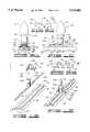
- FIG. 1is a side view in elevation in exploded form with parts shown in section of a Christmas light socket, track channel, molded snap button and mounting situs;
- FIG. 2is a view in side elevation of the FIG. 1 items when assembled into operative position
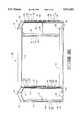
- FIG. 6is a side quarter perspective view of a storage rack constructed in accordance with the invention.
- FIG. 9Ais a side view in elevation with parts shown in section of an alternative form of Christmas light socket, track channel, and universal clip;
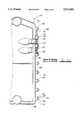
- FIG. 11is a partial end view of an alternative form of storage rack end frame
- a standard Christmas light string 10would consist of a plurality of standard outdoor Christmas bulbs 12 each seated in such as a molded plastic socket 14.
- the sockets 14may be of many variations but they are generally of a cylindrical shape having a feed-through 16 at or near the bottom which allows passage of a multi-wire cable, e.g., two wire pair, 18 to pass therethrough.
- the two wire pairpasses through the base of socket 14 and piercing tines connect the wire pairs of cable 18 to respective contacts within socket 14.
- a base flange 20is added to the bottom of each of the sockets 14 of the light string.
- the base flange 20would be included with the molded socket 14 to extend opposing corners 22 and 24 outward in predetermined extension.
- suitable disks forming base flange 20may be bonded to the bottom of respective light sockets 14. In either case, the outboard corners 22 and 24 provide a gripping surface for the track channel 26.
- Track channel 26is an extruded plastic or thin metal which is formed to have opposite side rails 28 and 30 extending at right angles from a base panel 32. The upper edges of side rails 28 and 30 each terminate with inward extending flanges 34 and 36 which provide gripping retention when positioned on flanges 22 and 24 of base flange 20.
- the track channel 26also includes a longitudinal, central snap channel 38 formed upward through channel base 32, and it is formed to include opposed channel retention beads 40 and 42 therealong to provide snap gripping, as will be further described.
- a molded snap button 44includes a base portion 46 and a larger radius button portion 48 which provides resilient, secure snap-fit within the longitudinal snap channel 38 of track channel 26.
- a suitable galvanized nail 50 or other fastenermay be used to secure the snap button 44 through hole 52 into the selected situs member 54 which may be a building roof, facia or other structure about the building.
- the track channel 26would normally be selected to be of a multiple of feet in length to contain a multiple of light sockets 14 and the respective light bulbs 12, as will be further described below. It should be noted, however, that only two snap buttons 44 need be mounted to provide secure positioning of the track channel 26.
- a plurality of spaced yard stakes 56each having a snap button 44 secured thereon, may be disposed at suitable distances apart on a lawn or garden situs to receive track channels 26 and a multiple of light bulbs 12.
- the light stringitself includes the base flange 20 on each socket 14 which are seized by opposite side rails 28 and 30 of track channel 26, and the lower snap track 38 secures on the respective snap buttons 44 supported on spaced stakes 56.
- FIG. 4illustrates the manner in which a 32-light outdoor light string may be rigged using four six-foot track channels 26-1, 26-2, 26-3 and 26-4.
- the light stringincludes a continuous two-wire pair 18 having an A-C plug 58 on one end and a female receptacle 60 on the other end with four eight-bulb light sections mounted on respective track channels 26-1 through 26-4.
- Each of the track channels 26includes approximately one-quarter of the length of the wire pair 18 along with eight of the light bulbs 12 as mounted in sockets 14 (FIG. 1) and including base flanges 20.
- the base flanges 20may be either round or square (as shown in FIG. 4), and the square type may be preferred since they prevent rotation of the socket 14 relative to track channel 26 when base flange 20 is locked within channel flanges 34 and 36 (FIG. 1).
- each individual section of track channel 26would support the wire pair 18 and eight light bulbs 12 in equi-spaced distribution therealong.
- each six-foot section of track channel 26would include eight lamp sockets 14 spaced eight inches apart with opposite end sockets 14 spaced four inches from the ends of track channel 26.
- the snap buttons 44 with fasteners 50would be secured into the building structure 54 at the designated location at about four to five foot spacing to receive secure affixture of the track channel 26 when installed. Should it be preferred to employ lawn or garden lighting, it is only necessary to secure the snap buttons 44 on top of yard stakes 56 (FIG. 3) at spacing similar to that employed in FIG. 5.
- the end frame 66includes opposite side risers 74 and 76 disposed in parallel and joined by a top brace 78 and a lower brace 80 which maintain the risers in parallel.
- a strengthening spar 82is formed across the mid-point of risers 74 and 76.
- a cylindrical cup 84is formed at a mid-point of upper brace 78 and oriented to receive tight insertion of upper tube 70.
- a cylindrical cup 86is formed at a mid-point of lower brace 80 to receive lower tube 72 firmly therein.
- Similar configurationis found on the opposite side end frame 68 which is formed with opposite risers 88 and 90 connected by upper brace 92 and cylindrical cup 94, and lower brace 96 which includes cylindrical cup 98. Then, in similar manner, the upper tube 70 is firmly received within cup 94 while the lower tube 72 is secured into cup 98.
- the outer side 100 of riser 74is formed with a plurality of pairs of opposed cleats 102 and 104, and each of the opposed cleats includes an oppositely oriented flange 106 and 108, respectively, which function to provide gripping surfaces to receive the track channels for storage, as will be further described below.
- An equal plurality of cleat pairs 102 and 104 having oppositely oriented flanges 106 and 108are also formed along the outside surface of riser 76.
- FIGS. 7A and 7Billustrate the cleat structure with greater clarity.
- a portion of riser 74is formed to have cleats 102 and 104 formed integrally on the side 122.
- Each of the cleats 102 and 104is formed with a respective opposite-extending flange 106 and 108 and a central strengthening vane 124 is mold-formed to extend between respective cleats 102 and 104 for longitudinal reinforcement.
- the side view of FIG. 7Billustrates the disposition of vane 124 as it extends between cleats 102 and 104.
- Similar structureis utilized at the opposite end frame 68 as reinforcing vane 126 extends in bisection between respective cleats 112 and 114.
- FIG. 8provides an end view of a storage rack 65 which is fully loaded with a plurality of light strings as retained on track channels 26.
- the storage rack 65could retain four such thirty-two light strings as supported on sixteen track channels 26, eight on each side.
- a single track channel 26may be snapped onto respective opposite end pairs of cleats 102 and 104 and 112 and 114, the cleat pairs occupying similar positions on the opposite end frames 66 and 68.
- the fully loaded storage rack 65may then be hand carried by means of top joinder tube 70 (FIG. 6) to a suitable storage location until next required usage.
- stored light sections on storage rack 65may be removed for snap-fit disposition on pre-arranged snap buttons 44 that have been previously secured to subtend the desired lighting array on rooftop, building facia or in yard stake array. If it is desired to change or alter the lighting arrangement it is only necessary to move the snap button 44 since the fasteners 50 may be re-secured at any desired position.
- each successive track channel 26may then be snapped onto paired cleat structure of the end frames 66 and 68 of the storage rack 65.
- the rack 65may be carried by means of top joinder tube 70 for placement in storage until next planned usage of the light system.
- the track mounted light stringsmay be divided up into any convenient number per track channel depending upon the overall number of lights.
- a normal or usual storage rack 65may be assembled with the top and bottom tubes 70 and 72 being of 48 inch lengths which easily accommodate the multiple of six foot track sections of the type shown in FIGS. 4 and 5.
- FIGS. 9A, 9B, 9C and 10there is illustrated an alternate design that is capable of adapting to most existing standard outdoor light strings.
- the lengths of light string 130are held in position in predetermined lengths of extruded track channel 138 by means of a plurality of universal clips 140 (FIG. 9C).
- the track channel 138may be extruded from suitable plastic or metal so long as it exhibits minimal resiliency.
- the track channel 138consists of a bottom panel 142 and a top panel 144 which are rigidly attached by opposite side parallel walls 146 and 148.
- the bottom panel 142includes a central channel 150 opening upward and defined on opposite side by interfering flanges 152 and 154.
- the central channel 150serves for snap seizure on the snap buttons 44 as they are selectively positioned.
- the top panel 144includes a central groove 156 along the length thereof, the groove 156 serving to retain the light cable 136 therein along its length. Laterally protruding flanges 158 and 160 extend outward on each side of top panel 144 for gripping purposes, as will be further described below.
- the universal clips 140may be extruded in lengths and then sliced into relatively thin strips, as shown in FIG. 10.
- Universal clip 140is formed to have an elongate central panel 162 (FIG. 9C) with opposite side, parallel yoke formations 164 and 166 formed on the ends.
- a central protrusion 168is formed to extend along the bottom of center panel 162, and this serves primarily for maintaining pressure against the cable 136 running within the central groove 156.
- the opposite side yokes 164 and 166are each formed semi-circularly to extend opposite side outer tines 170 and 172 in a generally vertical plane while each includes a respective inner flange 174 and 176 for gripping purposes.
- the light fixtures 130 of nearly all pre-existing types of Christmas light string as well as other serial light stringsare compatible for use with the track channels 138 and a plurality of universal clips 140.
- each of a pair of universal clips 140is secured closely on each side of each individual light socket 134 thereby to position and retain the electric cable 136 within groove 156 while also serving to prevent rotation of the socket 134 when replacing lamps or such.
- FIGS. 12 and 13illustrate the manner in which the same alternative form of track channel 138 may contain a miniature light string 200 with a multiple of sockets 206 by using an adaptor clip 202.
- the light string 200includes an electric cable 204, usually multi-conductor, which is adaptable to lie down within the elongate groove 156 in upper panel 144 of track channel 138.
- Each of lamp sockets 206 carrying lamp bulbs 208is then secured in position with an adaptor clip 202 while the cable 204 is clipped securely into track channel 138.
- the adaptor clip 202is a molded plastic item that includes the essential structure of universal clip 140 with a transverse central panel 210 having arcuate tines 212 and 214 formed on each side and terminating in respective inwardly directed flanges 216 and 218.
- a resilient, circular clip 220is integrally formed at right angle to the transverse central panel 210. The circular clip 220 merely snaps around a lamp socket 206 so that the clip adaptor 202 may be snap-fit onto the top panel 144 of track channel 138 to maintain the electric cable 204 down within the groove 156.
- a clip adaptor 202is utilized with each lamp socket 206 along each segment of electric cable 204 as retained by each length of track channel 138.
- each track channel 138 having bottom panel 142will snap fit between a respective pair of lugs 190 in storage rack 65 (FIG. 11).
- the miniature lights 200are very closely spaced along the length of the electric cable 204 such that a full complement of track channels 138 assemble to contain successive lengths of miniature light string 200 thereby to enable a great multitude of individual lights to be carried on the storage rack 65.
- FIG. 11with both sides of storage rack 65 filled, i.e., eight lengths of track channel 138 carried on each side of the storage rack, there would be as much as ninety-six feet of individual light segments.
- Such light stringsmay be continuous or they may be segmented and connected in succession.
Landscapes
- Engineering & Computer Science (AREA)
- General Engineering & Computer Science (AREA)
- Non-Portable Lighting Devices Or Systems Thereof (AREA)
- Warehouses Or Storage Devices (AREA)
Abstract
Description
Claims (20)
Priority Applications (3)
| Application Number | Priority Date | Filing Date | Title |
|---|---|---|---|
| US08/429,895US5513081A (en) | 1995-04-27 | 1995-04-27 | Multiple light installation and storage system |
| CA002167641ACA2167641C (en) | 1995-04-27 | 1996-01-19 | Multiple light installation and storage system |
| EP96301164AEP0740105A1 (en) | 1995-04-27 | 1996-02-21 | Multiple light installation and storage system |
Applications Claiming Priority (1)
| Application Number | Priority Date | Filing Date | Title |
|---|---|---|---|
| US08/429,895US5513081A (en) | 1995-04-27 | 1995-04-27 | Multiple light installation and storage system |
Publications (1)
| Publication Number | Publication Date |
|---|---|
| US5513081Atrue US5513081A (en) | 1996-04-30 |
Family
ID=23705163
Family Applications (1)
| Application Number | Title | Priority Date | Filing Date |
|---|---|---|---|
| US08/429,895Expired - Fee RelatedUS5513081A (en) | 1995-04-27 | 1995-04-27 | Multiple light installation and storage system |
Country Status (3)
| Country | Link |
|---|---|
| US (1) | US5513081A (en) |
| EP (1) | EP0740105A1 (en) |
| CA (1) | CA2167641C (en) |
Cited By (43)
| Publication number | Priority date | Publication date | Assignee | Title |
|---|---|---|---|---|
| US5664877A (en)* | 1994-04-01 | 1997-09-09 | Wu; Jeng-Shyong | Decorative lamp string assembly |
| USD386003S (en)* | 1995-03-31 | 1997-11-11 | Schroeder Lyman L | Suspendable carrier for decorative lights |
| USD392399S (en) | 1997-03-28 | 1998-03-17 | Norman Yates | Christmas tinsel lights |
| GB2317945A (en)* | 1996-10-07 | 1998-04-08 | Shining Blick Enterprises Co L | A Figure Light |
| US5788362A (en)* | 1997-03-10 | 1998-08-04 | Chou; Tsung-Ming | Light string fixing structure |
| US5813751A (en)* | 1996-07-01 | 1998-09-29 | Shaffer; Robert G. | Device for permanent installation of christmas lighting |
| US5893628A (en)* | 1996-02-26 | 1999-04-13 | Byers; Thomas L. | Multiple light systems |
| US5907945A (en)* | 1998-06-04 | 1999-06-01 | Doyle; Donald E. | Holiday light storage and stacking apparatus and method |
| US5911633A (en)* | 1997-04-01 | 1999-06-15 | Hms Mfg. Co. | Decorative surround for a Christmas tree display stand |
| US5941627A (en)* | 1997-04-02 | 1999-08-24 | Sacher; Dominic | Lighting conductor rail system |
| US5941388A (en)* | 1998-05-27 | 1999-08-24 | Spielberger; William L. | Christmas light storage system |
| US6176600B1 (en)* | 2000-01-06 | 2001-01-23 | Ming-Hsien Huang | Decorative lighting net |
| US6231210B1 (en)* | 1999-12-15 | 2001-05-15 | General Electric Compan | Fixed frame configured string set |
| US6366214B1 (en)* | 2000-01-10 | 2002-04-02 | Ronald L. Mitchell | Warning light |
| US6364508B1 (en) | 2000-05-16 | 2002-04-02 | Karren Moreland | Channel system for light strings |
| US6485161B1 (en)* | 2001-05-25 | 2002-11-26 | Beatrice M. Whitaker | Outdoor decorative lighting system |
| US6520661B1 (en)* | 2002-01-18 | 2003-02-18 | Sharon K. Hill | Decorative light assembly |
| US6572239B1 (en) | 2002-02-22 | 2003-06-03 | Michael R. Harbin | Storage and display apparatus |
| US6652121B1 (en) | 2002-05-31 | 2003-11-25 | Paula D. Kneeshaw | Positionable lighting system |
| US6693391B2 (en)* | 2002-02-08 | 2004-02-17 | Joseph M. Ahroni | Decorative lighting apparatus |
| US20060239014A1 (en)* | 2005-04-26 | 2006-10-26 | Hung-Huei Cheng | Bulb assemblies of light string with various connective status |
| US7159998B2 (en) | 2002-03-26 | 2007-01-09 | Karren Moreland | Channel system for light strings |
| USD536606S1 (en) | 2006-02-03 | 2007-02-13 | Emerald Innovations L.L.C. | Clip |
| USD547170S1 (en) | 2006-02-03 | 2007-07-24 | Emerald Innovations L.L.C. | Clip |
| US20070211453A1 (en)* | 2006-03-08 | 2007-09-13 | Chris Hamburger | Holiday lighting track system |
| US20070211462A1 (en)* | 2006-03-07 | 2007-09-13 | Dowell Robbie A | Accessory attachment apparatus |
| USD554790S1 (en)* | 2005-03-18 | 2007-11-06 | B + G Lighting, Llc | Holiday lawn light |
| US20080037244A1 (en)* | 2006-08-11 | 2008-02-14 | Target Brands, Inc. | Light display unit with fixture and light strand |
| US7334921B1 (en) | 2007-04-17 | 2008-02-26 | Richard Simnor | Flexible lighting system |
| USD570004S1 (en) | 2006-08-11 | 2008-05-27 | Target Brands, Inc. | Light display fixture |
| US20080298049A1 (en)* | 2007-06-01 | 2008-12-04 | Creative Industries, Llc | Baluster lighting assembly and method |
| US20110007510A1 (en)* | 2009-07-10 | 2011-01-13 | Lloyd Plumb | Lighted moving ball display system |
| US8403535B1 (en) | 2010-02-18 | 2013-03-26 | Clarence E. Keith, Jr. | Lighting system |
| US8721121B1 (en)* | 2009-12-24 | 2014-05-13 | Roger Daniel Briles | Decorative light string with blinking lights |
| US8789972B2 (en) | 2009-07-10 | 2014-07-29 | Lloyd R. Plumb | Lighted moving ball display system |
| US20140286010A1 (en)* | 2013-03-19 | 2014-09-25 | Steve McLaren | Luma Lights |
| CN105066070A (en)* | 2015-07-29 | 2015-11-18 | 漳州立达信光电子科技有限公司 | Bulb Orientation Mechanism |
| US20160111817A1 (en)* | 2014-10-20 | 2016-04-21 | Enphase Energy, Inc. | Method and apparatus for securing a segmented power cable for shipping and storage |
| US10145116B2 (en)* | 2015-12-29 | 2018-12-04 | Araystays Corporation | Apparatus and methods for secure, non-invasive and non-permanent surface attachment systems |
| US20200041118A1 (en)* | 2018-08-03 | 2020-02-06 | Lamplight Farms Incorporated | Repellant string light |
| USD950112S1 (en)* | 2021-01-15 | 2022-04-26 | Lihua Zheng | String lamp |
| US11754279B2 (en) | 2018-08-03 | 2023-09-12 | Lamplight Farms Incorporated | Repellant string light |
| US12414556B2 (en) | 2018-08-03 | 2025-09-16 | Lamplight Farms Incorporated | Repellant string light and retrofit assembly |
Families Citing this family (3)
| Publication number | Priority date | Publication date | Assignee | Title |
|---|---|---|---|---|
| DE602006012850D1 (en) | 2005-06-02 | 2010-04-22 | Cheng Chung Wai Paul | LIGHT CHAIN SYSTEM |
| US7252421B2 (en) | 2005-10-05 | 2007-08-07 | A & L Assembly, Llc | Vehicular light assembly and related method |
| US7980871B2 (en) | 2008-10-20 | 2011-07-19 | Polygroup Macau Limited (Bvi) | Light string system |
Citations (21)
| Publication number | Priority date | Publication date | Assignee | Title |
|---|---|---|---|---|
| US2889451A (en)* | 1958-03-14 | 1959-06-02 | Gregory W Longo | Mounting device for strand supported elements |
| US3189310A (en)* | 1962-05-18 | 1965-06-15 | Trueson Joseph | Christmas outside light holder |
| US3204090A (en)* | 1962-07-11 | 1965-08-31 | Jr Charles Kvarda | Christmas light holder |
| US3384227A (en)* | 1966-08-29 | 1968-05-21 | William L. Spatz | Christmas tree lights storage container |
| US3404268A (en)* | 1966-12-23 | 1968-10-01 | Lawrence M. Fowler | Formable light strip |
| US3540687A (en)* | 1969-10-31 | 1970-11-17 | Angelo C Cuva | Light socket retainer |
| US4128863A (en)* | 1977-05-16 | 1978-12-05 | Michael J. Premetz | Stowable decorative lights |
| US4357653A (en)* | 1980-08-18 | 1982-11-02 | Kovacs Michael J | Christmas light frame |
| US4491902A (en)* | 1982-09-03 | 1985-01-01 | Cangelosi Frank V | Combination mounting bracket and light socket |
| US4769749A (en)* | 1987-05-14 | 1988-09-06 | William Felski | Mounting device for a decorative string or Christmas tree light assembly |
| US5024406A (en)* | 1990-01-31 | 1991-06-18 | Ketcham Raymond H | Device for hanging outdoor Christmas lights |
| US5033619A (en)* | 1990-06-13 | 1991-07-23 | Garis Cynthia L | Light string carrier |
| US5036447A (en)* | 1990-06-29 | 1991-07-30 | Handi-Pac, Inc. | Light stake |
| US5064067A (en)* | 1990-09-17 | 1991-11-12 | Mcallister James D | Christmas light organizer |
| US5067061A (en)* | 1990-01-12 | 1991-11-19 | Prickett Robert B | Decorative exterior trim lighting system |
| US5110078A (en)* | 1988-10-13 | 1992-05-05 | Gary Products Group, Inc. | Decorative light support assembly |
| US5168999A (en)* | 1991-06-28 | 1992-12-08 | Continential Lighting Ind. Inc. | System for packaging string lights |
| US5238425A (en)* | 1990-10-01 | 1993-08-24 | Kliewer Wesley P | Mounting apparatus |
| US5297013A (en)* | 1991-08-09 | 1994-03-22 | Brinkmann Corporation | Outdoor light fixture |
| US5317491A (en)* | 1992-08-03 | 1994-05-31 | Lee Kuo Hsing | Holder for string of electric lights |
| US5355288A (en)* | 1993-04-21 | 1994-10-11 | Noma, Inc. | Lampholder and mounting means therefor |
Family Cites Families (1)
| Publication number | Priority date | Publication date | Assignee | Title |
|---|---|---|---|---|
| US4888671A (en)* | 1988-03-14 | 1989-12-19 | Peter Reimer | Ornamental strip light mounting means |
- 1995
- 1995-04-27USUS08/429,895patent/US5513081A/ennot_activeExpired - Fee Related
- 1996
- 1996-01-19CACA002167641Apatent/CA2167641C/ennot_activeExpired - Fee Related
- 1996-02-21EPEP96301164Apatent/EP0740105A1/ennot_activeWithdrawn
Patent Citations (21)
| Publication number | Priority date | Publication date | Assignee | Title |
|---|---|---|---|---|
| US2889451A (en)* | 1958-03-14 | 1959-06-02 | Gregory W Longo | Mounting device for strand supported elements |
| US3189310A (en)* | 1962-05-18 | 1965-06-15 | Trueson Joseph | Christmas outside light holder |
| US3204090A (en)* | 1962-07-11 | 1965-08-31 | Jr Charles Kvarda | Christmas light holder |
| US3384227A (en)* | 1966-08-29 | 1968-05-21 | William L. Spatz | Christmas tree lights storage container |
| US3404268A (en)* | 1966-12-23 | 1968-10-01 | Lawrence M. Fowler | Formable light strip |
| US3540687A (en)* | 1969-10-31 | 1970-11-17 | Angelo C Cuva | Light socket retainer |
| US4128863A (en)* | 1977-05-16 | 1978-12-05 | Michael J. Premetz | Stowable decorative lights |
| US4357653A (en)* | 1980-08-18 | 1982-11-02 | Kovacs Michael J | Christmas light frame |
| US4491902A (en)* | 1982-09-03 | 1985-01-01 | Cangelosi Frank V | Combination mounting bracket and light socket |
| US4769749A (en)* | 1987-05-14 | 1988-09-06 | William Felski | Mounting device for a decorative string or Christmas tree light assembly |
| US5110078A (en)* | 1988-10-13 | 1992-05-05 | Gary Products Group, Inc. | Decorative light support assembly |
| US5067061A (en)* | 1990-01-12 | 1991-11-19 | Prickett Robert B | Decorative exterior trim lighting system |
| US5024406A (en)* | 1990-01-31 | 1991-06-18 | Ketcham Raymond H | Device for hanging outdoor Christmas lights |
| US5033619A (en)* | 1990-06-13 | 1991-07-23 | Garis Cynthia L | Light string carrier |
| US5036447A (en)* | 1990-06-29 | 1991-07-30 | Handi-Pac, Inc. | Light stake |
| US5064067A (en)* | 1990-09-17 | 1991-11-12 | Mcallister James D | Christmas light organizer |
| US5238425A (en)* | 1990-10-01 | 1993-08-24 | Kliewer Wesley P | Mounting apparatus |
| US5168999A (en)* | 1991-06-28 | 1992-12-08 | Continential Lighting Ind. Inc. | System for packaging string lights |
| US5297013A (en)* | 1991-08-09 | 1994-03-22 | Brinkmann Corporation | Outdoor light fixture |
| US5317491A (en)* | 1992-08-03 | 1994-05-31 | Lee Kuo Hsing | Holder for string of electric lights |
| US5355288A (en)* | 1993-04-21 | 1994-10-11 | Noma, Inc. | Lampholder and mounting means therefor |
Cited By (59)
| Publication number | Priority date | Publication date | Assignee | Title |
|---|---|---|---|---|
| US5664877A (en)* | 1994-04-01 | 1997-09-09 | Wu; Jeng-Shyong | Decorative lamp string assembly |
| USD386003S (en)* | 1995-03-31 | 1997-11-11 | Schroeder Lyman L | Suspendable carrier for decorative lights |
| US5957568A (en)* | 1996-02-26 | 1999-09-28 | Byers; Thomas L. | Multiple light systems and covers therefor |
| US5893628A (en)* | 1996-02-26 | 1999-04-13 | Byers; Thomas L. | Multiple light systems |
| US5813751A (en)* | 1996-07-01 | 1998-09-29 | Shaffer; Robert G. | Device for permanent installation of christmas lighting |
| GB2317945A (en)* | 1996-10-07 | 1998-04-08 | Shining Blick Enterprises Co L | A Figure Light |
| GB2317945B (en)* | 1996-10-07 | 2000-03-29 | Shining Blick Enterprises Co L | Figure light |
| US5788362A (en)* | 1997-03-10 | 1998-08-04 | Chou; Tsung-Ming | Light string fixing structure |
| GB2323154B (en)* | 1997-03-10 | 2001-06-20 | Chou Tsung Ming | A light string fixing structure |
| USD392399S (en) | 1997-03-28 | 1998-03-17 | Norman Yates | Christmas tinsel lights |
| US5911633A (en)* | 1997-04-01 | 1999-06-15 | Hms Mfg. Co. | Decorative surround for a Christmas tree display stand |
| US6041545A (en)* | 1997-04-01 | 2000-03-28 | Hms Mfg. Co. | Decorative surround for display stand |
| US5941627A (en)* | 1997-04-02 | 1999-08-24 | Sacher; Dominic | Lighting conductor rail system |
| US5941388A (en)* | 1998-05-27 | 1999-08-24 | Spielberger; William L. | Christmas light storage system |
| US5907945A (en)* | 1998-06-04 | 1999-06-01 | Doyle; Donald E. | Holiday light storage and stacking apparatus and method |
| US6231210B1 (en)* | 1999-12-15 | 2001-05-15 | General Electric Compan | Fixed frame configured string set |
| US6176600B1 (en)* | 2000-01-06 | 2001-01-23 | Ming-Hsien Huang | Decorative lighting net |
| US6366214B1 (en)* | 2000-01-10 | 2002-04-02 | Ronald L. Mitchell | Warning light |
| US6364508B1 (en) | 2000-05-16 | 2002-04-02 | Karren Moreland | Channel system for light strings |
| US6485161B1 (en)* | 2001-05-25 | 2002-11-26 | Beatrice M. Whitaker | Outdoor decorative lighting system |
| US6520661B1 (en)* | 2002-01-18 | 2003-02-18 | Sharon K. Hill | Decorative light assembly |
| US6693391B2 (en)* | 2002-02-08 | 2004-02-17 | Joseph M. Ahroni | Decorative lighting apparatus |
| US6572239B1 (en) | 2002-02-22 | 2003-06-03 | Michael R. Harbin | Storage and display apparatus |
| US7159998B2 (en) | 2002-03-26 | 2007-01-09 | Karren Moreland | Channel system for light strings |
| US6652121B1 (en) | 2002-05-31 | 2003-11-25 | Paula D. Kneeshaw | Positionable lighting system |
| USD554790S1 (en)* | 2005-03-18 | 2007-11-06 | B + G Lighting, Llc | Holiday lawn light |
| US20060239014A1 (en)* | 2005-04-26 | 2006-10-26 | Hung-Huei Cheng | Bulb assemblies of light string with various connective status |
| US7223012B2 (en)* | 2005-04-26 | 2007-05-29 | Hung-Huei Cheng | Bulb assemblies of light string with various connective status |
| USD547170S1 (en) | 2006-02-03 | 2007-07-24 | Emerald Innovations L.L.C. | Clip |
| USD536606S1 (en) | 2006-02-03 | 2007-02-13 | Emerald Innovations L.L.C. | Clip |
| US20070211462A1 (en)* | 2006-03-07 | 2007-09-13 | Dowell Robbie A | Accessory attachment apparatus |
| US20070211453A1 (en)* | 2006-03-08 | 2007-09-13 | Chris Hamburger | Holiday lighting track system |
| US20080037244A1 (en)* | 2006-08-11 | 2008-02-14 | Target Brands, Inc. | Light display unit with fixture and light strand |
| USD570004S1 (en) | 2006-08-11 | 2008-05-27 | Target Brands, Inc. | Light display fixture |
| USD572861S1 (en) | 2006-08-11 | 2008-07-08 | Target Brands, Inc. | Light display fixture |
| US7600895B2 (en) | 2006-08-11 | 2009-10-13 | Target Brands, Inc. | Light display unit with fixture and light strand |
| US7334921B1 (en) | 2007-04-17 | 2008-02-26 | Richard Simnor | Flexible lighting system |
| US20080298049A1 (en)* | 2007-06-01 | 2008-12-04 | Creative Industries, Llc | Baluster lighting assembly and method |
| US7722207B2 (en)* | 2007-06-01 | 2010-05-25 | Creative Industries, Llc | Baluster lighting assembly and method |
| US8789972B2 (en) | 2009-07-10 | 2014-07-29 | Lloyd R. Plumb | Lighted moving ball display system |
| US20110007510A1 (en)* | 2009-07-10 | 2011-01-13 | Lloyd Plumb | Lighted moving ball display system |
| US8348466B2 (en) | 2009-07-10 | 2013-01-08 | Lloyd Plumb | Lighted moving ball display system |
| US8721121B1 (en)* | 2009-12-24 | 2014-05-13 | Roger Daniel Briles | Decorative light string with blinking lights |
| US8403535B1 (en) | 2010-02-18 | 2013-03-26 | Clarence E. Keith, Jr. | Lighting system |
| US20140286010A1 (en)* | 2013-03-19 | 2014-09-25 | Steve McLaren | Luma Lights |
| US10797435B2 (en)* | 2014-10-20 | 2020-10-06 | Enphase Energy, Inc. | Method and apparatus for securing a segmented power cable for shipping and storage |
| US20160111817A1 (en)* | 2014-10-20 | 2016-04-21 | Enphase Energy, Inc. | Method and apparatus for securing a segmented power cable for shipping and storage |
| CN105066070A (en)* | 2015-07-29 | 2015-11-18 | 漳州立达信光电子科技有限公司 | Bulb Orientation Mechanism |
| CN105066070B (en)* | 2015-07-29 | 2022-12-27 | 漳州立达信光电子科技有限公司 | Bulb orienting mechanism |
| US10822801B2 (en) | 2015-12-29 | 2020-11-03 | Araystays Corporation | Apparatus and methods for a noninvasive roof attachment system with vertical members |
| US10640981B2 (en) | 2015-12-29 | 2020-05-05 | John Granville Holt | Apparatus and methods for secure, non-invasive and non-permanent surface attachment systems |
| US10815667B2 (en) | 2015-12-29 | 2020-10-27 | Araystays Corporation | Apparatus and methods for a noninvasive roof attachment system with vertical members |
| US11193279B2 (en) | 2015-12-29 | 2021-12-07 | John Granville Holt | Noninvasive roof attachment with vertical and lateral array stays |
| US10145116B2 (en)* | 2015-12-29 | 2018-12-04 | Araystays Corporation | Apparatus and methods for secure, non-invasive and non-permanent surface attachment systems |
| US20200041118A1 (en)* | 2018-08-03 | 2020-02-06 | Lamplight Farms Incorporated | Repellant string light |
| US10962219B2 (en)* | 2018-08-03 | 2021-03-30 | Lamplight Farms Incorporated | Repellant string light |
| US11754279B2 (en) | 2018-08-03 | 2023-09-12 | Lamplight Farms Incorporated | Repellant string light |
| US12414556B2 (en) | 2018-08-03 | 2025-09-16 | Lamplight Farms Incorporated | Repellant string light and retrofit assembly |
| USD950112S1 (en)* | 2021-01-15 | 2022-04-26 | Lihua Zheng | String lamp |
Also Published As
| Publication number | Publication date |
|---|---|
| CA2167641A1 (en) | 1996-10-28 |
| CA2167641C (en) | 1999-01-26 |
| EP0740105A1 (en) | 1996-10-30 |
Similar Documents
| Publication | Publication Date | Title |
|---|---|---|
| US5513081A (en) | Multiple light installation and storage system | |
| US5957568A (en) | Multiple light systems and covers therefor | |
| US5667174A (en) | Decorative light stake | |
| US5772166A (en) | Mounting clip | |
| US3540687A (en) | Light socket retainer | |
| US5469344A (en) | Support for decorative light string on a building | |
| AU769840B2 (en) | Variable-position decorative light mounting system | |
| US6027228A (en) | Christmas tree lawn ornament | |
| US5566058A (en) | Light clip for shingles or gutters | |
| US5601361A (en) | Celebration electric light net | |
| US4447279A (en) | Automatic artificial tree | |
| US2889451A (en) | Mounting device for strand supported elements | |
| US4974128A (en) | Rapidly adjustable decorative exterior trim lighting system | |
| US6585234B2 (en) | Fencing system | |
| US5758948A (en) | Seasonal light display device | |
| GB2093436A (en) | Trough units for holding flowers | |
| US20020149936A1 (en) | Decorative lighting assembly | |
| US5531411A (en) | Mounting clip for decorative lights | |
| US20180245733A1 (en) | Enclosed Gutter Clip | |
| US20170198871A1 (en) | Reconfigurable Lighting System | |
| US4888671A (en) | Ornamental strip light mounting means | |
| US5647660A (en) | Modular light display apparatus | |
| US5536538A (en) | Artificial christmas tree | |
| US6179440B1 (en) | Rope light | |
| US6361187B1 (en) | Christmas tree outdoor ornament |
Legal Events
| Date | Code | Title | Description |
|---|---|---|---|
| AS | Assignment | Owner name:BYERS INVESTMENTS, OKLAHOMA Free format text:ASSIGNMENT OF ASSIGNORS INTEREST;ASSIGNOR:BYERS, THOMAS L.;REEL/FRAME:008094/0018 Effective date:19960816 | |
| FPAY | Fee payment | Year of fee payment:4 | |
| AS | Assignment | Owner name:GARY PRODUCTS GROUP, INC., TEXAS Free format text:ASSIGNMENT OF ASSIGNORS INTEREST;ASSIGNOR:BYERS PRODUCTS, INC., A CORPORATION OF OKLAHOMA;REEL/FRAME:010710/0318 Effective date:20000218 | |
| AS | Assignment | Owner name:WELLS FARGO BANK, N.A., CALIFORNIA Free format text:SECURITY AGREEMENT;ASSIGNOR:GARY PRODUCTS GROUP, INC.;REEL/FRAME:010719/0094 Effective date:20000218 | |
| AS | Assignment | Owner name:EMERALD INNOVATIONS, L.L.C., OHIO Free format text:BILL OF SALE;ASSIGNOR:GARY PRODUCTS GROUP, INC.;REEL/FRAME:013203/0769 Effective date:20011220 | |
| REMI | Maintenance fee reminder mailed | ||
| REMI | Maintenance fee reminder mailed | ||
| LAPS | Lapse for failure to pay maintenance fees | ||
| FP | Lapsed due to failure to pay maintenance fee | Effective date:20040430 | |
| STCH | Information on status: patent discontinuation | Free format text:PATENT EXPIRED DUE TO NONPAYMENT OF MAINTENANCE FEES UNDER 37 CFR 1.362 |